JP4312080B2 - Communication method and apparatus - Google Patents
Communication method and apparatus Download PDFInfo
- Publication number
- JP4312080B2 JP4312080B2 JP2004054439A JP2004054439A JP4312080B2 JP 4312080 B2 JP4312080 B2 JP 4312080B2 JP 2004054439 A JP2004054439 A JP 2004054439A JP 2004054439 A JP2004054439 A JP 2004054439A JP 4312080 B2 JP4312080 B2 JP 4312080B2
- Authority
- JP
- Japan
- Prior art keywords
- transmission
- standby
- byte
- active
- phase
- Prior art date
- Legal status (The legal status is an assumption and is not a legal conclusion. Google has not performed a legal analysis and makes no representation as to the accuracy of the status listed.)
- Expired - Fee Related
Links
- 238000004891 communication Methods 0.000 title claims description 24
- 238000000034 method Methods 0.000 title claims description 21
- 230000005540 biological transmission Effects 0.000 claims description 231
- 230000015654 memory Effects 0.000 claims description 69
- 238000003780 insertion Methods 0.000 claims description 28
- 230000037431 insertion Effects 0.000 claims description 28
- 238000001514 detection method Methods 0.000 claims description 18
- 230000003287 optical effect Effects 0.000 description 9
- 238000010586 diagram Methods 0.000 description 7
- 238000012545 processing Methods 0.000 description 6
- 230000001360 synchronised effect Effects 0.000 description 5
- 238000010521 absorption reaction Methods 0.000 description 3
- 239000013307 optical fiber Substances 0.000 description 2
- 238000005516 engineering process Methods 0.000 description 1
- 230000010354 integration Effects 0.000 description 1
- 238000012423 maintenance Methods 0.000 description 1
- 230000010363 phase shift Effects 0.000 description 1
- 230000008054 signal transmission Effects 0.000 description 1
Images


Classifications
-
- H—ELECTRICITY
- H04—ELECTRIC COMMUNICATION TECHNIQUE
- H04J—MULTIPLEX COMMUNICATION
- H04J3/00—Time-division multiplex systems
- H04J3/02—Details
- H04J3/14—Monitoring arrangements
-
- H—ELECTRICITY
- H04—ELECTRIC COMMUNICATION TECHNIQUE
- H04J—MULTIPLEX COMMUNICATION
- H04J2203/00—Aspects of optical multiplex systems other than those covered by H04J14/05 and H04J14/07
- H04J2203/0001—Provisions for broadband connections in integrated services digital network using frames of the Optical Transport Network [OTN] or using synchronous transfer mode [STM], e.g. SONET, SDH
- H04J2203/0057—Operations, administration and maintenance [OAM]
- H04J2203/006—Fault tolerance and recovery
-
- H—ELECTRICITY
- H04—ELECTRIC COMMUNICATION TECHNIQUE
- H04J—MULTIPLEX COMMUNICATION
- H04J2203/00—Aspects of optical multiplex systems other than those covered by H04J14/05 and H04J14/07
- H04J2203/0001—Provisions for broadband connections in integrated services digital network using frames of the Optical Transport Network [OTN] or using synchronous transfer mode [STM], e.g. SONET, SDH
- H04J2203/0089—Multiplexing, e.g. coding, scrambling, SONET
- H04J2203/0096—Serial Concatenation
Landscapes
- Engineering & Computer Science (AREA)
- Computer Networks & Wireless Communication (AREA)
- Signal Processing (AREA)
- Time-Division Multiplex Systems (AREA)
- Synchronisation In Digital Transmission Systems (AREA)
- Detection And Prevention Of Errors In Transmission (AREA)
Description
本発明は、通信方式に関し、特に長距離の伝送路の運用系と予備系とを無瞬断で切り換え可能な通信方法及び装置に関するものである。 The present invention relates to a communication system, and more particularly to a communication method and apparatus capable of switching between an operation system and a backup system of a long-distance transmission path without interruption.
従来より、SDH(Synchronous Digital Hierarchy)/SONET(Synchronous Optical Network)の多重化伝送システムにおいて、伝送路を冗長構成とし運用系の伝送路に障害等が発生した場合に予備系の伝送路に切り替える無瞬断通信方式が採用されている。 Conventionally, in an SDH (Synchronous Digital Hierarchy) / SONET (Synchronous Optical Network) multiplexed transmission system, there is no need to switch to a standby transmission path when the transmission path has a redundant configuration and a failure occurs in the active transmission path. An instantaneous interruption communication method is adopted.
無瞬断通信方式の従来例としては、送信側でSDHフレームのパスオーバヘッド(以下、POHと略称することがある。)のJ1バイトの入力データにマルチフレームを構成して2つの方路に分岐して送信し、受信側では、2つの方路から受信した信号についてJ1バイトの入力データによりマルチフレーム同期を確立し、検出した位相差を吸収するものがある(例えば、特許文献1参照。)。 As a conventional example of the uninterruptible communication method, a multi-frame is formed on J1 byte input data of the SDH frame path overhead (hereinafter, abbreviated as POH) on the transmission side, and branched into two routes. On the receiving side, multi-frame synchronization is established by J1 byte input data for signals received from two routes, and the detected phase difference is absorbed (for example, see Patent Document 1). .
このような、J1バイトの入力データによるマルチフレーム同期を確立する無瞬断通信方式を採用した送信装置の構成例を図6を用いて説明する。 A configuration example of a transmission apparatus that employs such an uninterruptible communication scheme that establishes multiframe synchronization using J1 byte input data will be described with reference to FIG.
同図に示す送信装置10は、データを入力するインタフェース11と、入力データにパスオーバヘッド及びセクションオーバヘッドをそれぞれ付加するPOH付加部12及びSOH付加部14と、SOH付加部14からの信号を0系(例えば現用系)インタフェース16及び1系(例えば予備系)インタフェース17に分岐する分配部15と、POH付加部12に位相情報を与える位相情報挿入部13とで構成されている。
The transmission apparatus 10 shown in the figure includes an
動作において、インタフェース11に入力されたデータの各フレームには、POH付加部12においてパスオーバヘッドが付加されるが、このとき、位相情報挿入部13によりフレームのパスオーバヘッドのJ1バイトに64マルチフレームの位相情報が挿入される。この後、フレームにはSOH付加部14でさらにセクションオーバヘッドが付加された後、分配部15によって分岐され、現用系である0系インタフェース16及び予備系である1系インタフェース17を介してそれぞれ、0系及び1系の光伝送信号として送出される。
In operation, a path overhead is added to each frame of data input to the
図7は、光伝送信号として送出される一般的なSDHフレームの例として、SDHにおける基本単位であるSTM-1多重化フレームの構成を示したものである。図示の如く、フレームはセクションオーバヘッド(SOH)と、3つのバーチャルコンテナVC3#1〜VC3#3とで構成されている。なお、バーチャルコンテナとは規格化された多重化の単位のことである。
FIG. 7 shows a configuration of an STM-1 multiplexed frame, which is a basic unit in SDH, as an example of a general SDH frame transmitted as an optical transmission signal. As shown in the figure, the frame is composed of a section overhead (SOH) and three virtual
各バーチャルコンテナVC-3#1〜VC-3#3には、それぞれパスオーバヘッド(POH)が付加されている。図中、バーチャルコンテナVC-3#1内にのみパスオーバヘッド(POH)が示されているが、他のバーチャルコンテナVC-3#2及びVC-3#3にもパスオーバヘッド(POH)は付加されている。 A path overhead (POH) is added to each of the virtual containers VC-3 # 1 to VC-3 # 3. In the figure, the path overhead (POH) is shown only in the virtual container VC-3 # 1, but the path overhead (POH) is also added to the other virtual containers VC-3 # 2 and VC-3 # 3. ing.
パスオーバヘッド(POH)には、J1バイト、B3バイト、C2バイト、G1バイト、F2バイト、H4バイト、F3バイト、K3バイト、及びN1バイトといったバイトが定義されている。 In the path overhead (POH), bytes such as J1 byte, B3 byte, C2 byte, G1 byte, F2 byte, H4 byte, F3 byte, K3 byte, and N1 byte are defined.
この内、図6に示した位相情報挿入部13では、J1バイトに64マルチフレームを構成するための位相情報を挿入する。 Among these, the phase information insertion unit 13 shown in FIG. 6 inserts phase information for composing 64 multiframes into the J1 byte.
従来の64マルチフレームを構成する場合における、J1バイトの挿入例を図8を用いて以下に説明する。 An example of J1 byte insertion in the case of configuring a conventional 64-multiframe will be described below with reference to FIG.
同図は、フレームのデータをシリアルに並べた様子を概略的に示したものであり、一部のJ1バイトの値のみを示している。 This figure schematically shows how the frame data is serially arranged, and shows only the values of some J1 bytes.
J1バイトには連続して"00"から"63"までの値が繰り返して挿入されることになる。従って、同図に右から左にJ1バイトの値は連続して"63","00","01","02"という具合に挿入されている。 A value from “00” to “63” is repeatedly inserted into the J1 byte. Therefore, the values of the J1 byte are inserted sequentially from right to left in the figure, such as “63”, “00”, “01”, “02”.
図9は、このような64マルチフレームを用いた無瞬断切換が実現可能な受信装置、すなわち図6に示した送信装置10に対向する受信装置20の構成例を示したものである。 FIG. 9 shows an example of the configuration of a receiving device that can realize such a non-instantaneous switching using 64 multiframes, that is, the receiving device 20 facing the transmitting device 10 shown in FIG.
図示の如く、受信装置20は、0系及び1系の光伝送信号をそれぞれ受信し、セクションオーバヘッド(SOH)を終端する0系インタフェース21及び1系インタフェース22を有している。
As shown in the figure, the receiving apparatus 20 includes a 0-
0系インタフェース21及び1系インタフェース22はそれぞれエラスティックメモリ25及び26が接続されており、両メモリ25及び26には共通してセレクタ28が接続され、さらにインタフェース29がセレクタ28に接続されている。
The 0-
また、0系インタフェース21及び1系インタフェース22には出力がそれぞれマルチフレーム同期回路23及び24が接続されており、マルチフレーム同期回路23及び24並びにエラスティックメモリ25及び26に共通して制御回路27が接続されている。
Also,
図6に示した送信装置10の0系インタフェース16及び1系インタフェース17から出力される時点では位相が同じであるが、インタフェース21及び22によってそれぞれ受信される0系及び1系の光伝送信号は共に図8に示した64マルチフレームを構成した伝送信号であり、受信時には伝送路の経路長差に起因して位相がずれた状態になっている。
The phase is the same at the time of output from the 0-
例えば、図8に示したJ1の値で比較すると、ある時点で0系インタフェース21で受信する伝送信号のJ1バイトの値が"00"であっても、1系インタフェース22で受信しているJ1バイトの値は"02"である、というように位相がずれることになる。
For example, when comparing with the value of J1 shown in FIG. 8, even if the value of the J1 byte of the transmission signal received by the 0-
この場合、伝送信号が2フレーム分1系インタフェースの方が、位相が進んでいることになり、この位相差をマルチフレーム同期回路23及び24並びに制御回路27で検出し、制御回路27はエラスティックメモリ25及び27に適切な制御情報を与えることによりセレクタ28に入力される信号は位相が同期したものになっている。従って、セレクタ28を外部制御により高速に動作させることにより、0系から1系に無瞬断で信号を切り替えることが可能となっている。
In this case, the phase of the transmission signal is more advanced in the 1-system interface for 2 frames, and this phase difference is detected by the
この場合の、位相差吸収の概要を図10に概念的に示す。同図(1)は0系信号と1系信号との間に位相差が生じている状態を示しており、これは、図9の0系及び1系のインタフェース21及び22が受信する信号の状態を概念的に示したものである。図中、アルファベット1文字が1フレーム分のデータを表し、各アルファベットを含むセルが1フレームを表しているものとする。
An outline of phase difference absorption in this case is conceptually shown in FIG. (1) in the figure shows a state in which a phase difference is generated between the 0-system signal and the 1-system signal, and this indicates that the signals received by the 0-system and 1-
従って、同図(1)では点線に示す如く、1系信号の方が6フレーム分位相が進んだ状態になっているが、同図(2)に示す位相差吸収後の状態では0系信号及び1系信号の位相が合った状態になっている。すなわち、同図(2)の状態がエラスティックメモリ25及びエラスティックメモリ26から出力される信号の状態である。
Therefore, as shown by the dotted line in Fig. 1 (1), the 1-system signal is in a state in which the phase has advanced by 6 frames, but in the state after phase difference absorption shown in Fig. 2 (2), the 0-system signal And the
以上、基本的な64マルチフレーム同期を用いた無瞬断通信方式について説明したが、他には、非同期データに対応した無瞬断切り替えやマルチフレーム構成でないデータの無瞬断切り替えを実現可能なものもある(例えば、特許文献2参照。)。 As described above, the basic non-interruptible communication method using 64 multi-frame synchronization has been explained, but other than that, it is possible to realize non-instantaneous switching corresponding to asynchronous data and non-multi-frame data without interruption. There are some (see, for example, Patent Document 2).
さらには、J1バイトの2バイトを固定バイトとインクリメントされるカウンタ値等の可変バイトにすることで、64フレーム以上のマルチフレームで位相合わせをするものもある(例えば、特許文献3参照。)。
現用系と予備系とで受信した伝送信号の位相がずれる原因は、主として無瞬断切り替え可能な伝送路の経路長差に起因しているため、上記のJ1バイトを使用した64マルチフレーム同期を用いた無瞬断通信方式では、無瞬断切り替え可能な経路長差に限界がある。 The cause of the phase shift of the transmission signal received in the active system and the standby system is mainly due to the path length difference of the transmission path that can be switched without interruption, so the 64 multi-frame synchronization using the J1 byte above is performed. In the uninterruptible communication method used, there is a limit to the path length difference that can be switched without instantaneously.
すなわち、1フレームが125μsであることから、64マルチフレームに相当する位相差Δtは、Δt=125μs×64=8msであり、光ファイバーによる信号伝送では1kmに5μs要することから、無瞬断切り替え可能な経路長差は、単純計算で8ms/5μs=1600kmとなる。 In other words, since one frame is 125 μs, the phase difference Δt corresponding to 64 multiframes is Δt = 125 μs × 64 = 8 ms, and signal transmission using an optical fiber requires 5 μs per 1 km, so switching is possible without interruption The path length difference is 8ms / 5μs = 1600km by simple calculation.
但し、これは現用系及び予備系の伝送路について、どの経路長がより長いかが判明している場合に、一方の伝送路の位相を固定することを前提とした理論上の最大値であって、どちらの伝送路の位相が進んでいるかが事前に分からないことを前提とすれば、この値の半分である800kmが理論値となり、さらにその他の位相遅延要因を考慮すると、実際に無瞬断切り替えが可能な経路長差は600km程度になる。 However, this is the theoretical maximum value based on the premise that the phase of one transmission line is fixed when it is known which path length is longer for the active and standby transmission lines. Assuming that the phase of the transmission path is not known in advance, 800 km, which is half of this value, is the theoretical value, and when considering other phase delay factors, there is actually no instantaneous interruption. The path length difference that can be switched is about 600 km.
図11は、伝送路の冗長構成例を示したものである。同図(1)は、単純な冗長構成を示しており、対向する送受信装置である伝送装置30及び40が現用の0系伝送路T_0及び予備の1系伝送路T_1で接続されている。この場合、0系伝送路T_0と予備の1系伝送路T_1との経路長差が600km以内であれば、上記の64マルチフレーム同期による無瞬断切り替えが可能である。
FIG. 11 shows an example of a redundant configuration of the transmission path. FIG. 1 (1) shows a simple redundant configuration, in which
しかしながら、近年では、光ファイバにより長距離の伝送が可能となり、同図(2)に示す如く、対向する伝送装置30及び40を0系伝送路T_0及び1系伝送路T_1で結ぶ場合に、0系伝送路T_0を伝送装置50及び60で中継し、1系伝送路T_1を伝送装置70,80,及び90で中継することが可能である。
However, in recent years, it has become possible to transmit over long distances using optical fibers.As shown in FIG. 2 (2), when the
この場合、0系伝送路T_0における各伝送装置30,50,60,及び40の間隔はそれぞれセクション区間1〜3であり、1系伝送路T_1における各伝送装置30,70,80,90,及び40の間隔はそれぞれセクション区間4〜7であり、さらに、伝送装置30と40との間隔がパス区間8である。
In this case, the intervals between the
この場合、0系伝送路T_0の経路長はセクション区間1〜3の経路長の合計となり、1系伝送路T_1の経路長はセクション区間4〜7の経路長の合計となる。
In this case, the path length of the
従って、複数の伝送装置を介した同図(2)のような構成の場合、0系伝送路T_0と1系伝送路T_1との経路長差が600kmを超えてしまう可能性が十分にあり、上記の64マルチフレーム同期による無瞬断切り替えが出来なくなる。 Therefore, in the case of the configuration as shown in FIG. 2 (2) via a plurality of transmission devices, there is a possibility that the path length difference between the 0-system transmission path T_0 and the 1-system transmission path T_1 exceeds 600 km, Uninterruptible switching due to the above 64 multi-frame synchronization becomes impossible.
一方、上記の特許文献3によれば、この経路長差を265,000kmとすることが可能であるとしているが、特許文献3の技術をシステム内の無瞬断通信装置全てに適用する必要があり、図8に示したようにJ1バイトに位相情報を挿入して64マルチフレーム同期を行なう従来の通信装置に対する上位互換性が無いという問題点がある。
On the other hand, according to
すなわち、同図(2)のような構成のシステムにおいて、対向する伝送装置30及び40が共に図8に示した64マルチフレームを用いるものである場合、一方の伝送装置のみについて特許文献3の技術を適用することは出来ない。
That is, in the system having the configuration as shown in FIG. 2 (2), when the
これは、特許文献3による64マルチバイトが、J1バイトの64マルチフレームの最後の2バイトを固定バイトとインクリメントされるカウンタ値等の可変バイトにしたものであるため、図8に示した64マルチフレームとは少なくとも最後の2バイトについて異なってしまうためである。
This is because 64 multibytes according to
このため、従来の送信装置からの64マルチフレームを受信した特許文献3による受信装置は64マルチフレーム同期を行なえず、逆に、特許文献3による送信装置からの64マルチフレームを受信した従来の受信装置も従来の64マルチフレーム同期を行うことが出来ない。
Therefore, the receiving device according to
従って、本発明は600kmを越える経路長差を有する冗長構成の伝送路において無瞬断通信を可能にすると共に、上位互換性のある通信方法及び装置を提供することを目的とする。 Accordingly, it is an object of the present invention to provide a communication method and apparatus that allow uninterrupted communication on a redundant transmission line having a path length difference exceeding 600 km and that is upward compatible.
上記の目的を達成するため、本発明に係る通信方法は、送信側で、マルチフレームを構成するように伝送信号の各単一フレームのパスオーバヘッド中の少なくとも2つの所定バイトにそれぞれ順次位相情報を分割挿入するステップと、該伝送信号を現用系及び予備系の伝送路に分岐して伝送するステップと、受信側で、該現用系及び予備系の伝送路からそれぞれ受信した該伝送信号について該所定バイト毎に検出した該位相情報に基づき該現用系及び予備系の該伝送信号間の位相差を検出するステップと、該伝送信号をそれぞれ該現用系及び予備系のメモリに格納するステップと、該位相差に基づき位相調整信号を該現用系及び予備系のメモリに与えるステップと、該位相調整信号に基づき同位相の状態で該伝送信号を該現用系及び予備系のメモリからそれぞれ出力するステップと、該現用系及び予備系のメモリのいずれか一方から出力された該伝送信号を選択するステップと、を備えたことを特徴としている。 In order to achieve the above object, the communication method according to the present invention, on the transmission side, sequentially outputs phase information to at least two predetermined bytes in the path overhead of each single frame of a transmission signal so as to form a multiframe. A step of dividing and inserting; a step of branching and transmitting the transmission signal to the transmission line of the active system and the standby system; and a transmission side of the transmission signal received from the transmission path of the active system and the standby system on the receiving side. Detecting a phase difference between the transmission signals of the active system and the standby system based on the phase information detected for each byte; storing the transmission signals in the memories of the active system and the standby system, respectively; Applying a phase adjustment signal to the active and standby memories based on the phase difference; and transmitting the transmission signal in the same phase based on the phase adjustment signal to the active and standby systems. A step of outputting from each memory, and a step of selecting the transmission signal output from any one of the active and standby memories.
すなわち、送信側では、伝送信号の各単一フレームのパスオーバヘッド中の少なくとも2つの所定バイトに順次位相情報をそれぞれ分割挿入することにより、少なくとも2段のマルチフレームを構成した後、該伝送信号を現用系及び予備系の伝送路に分岐して送信する。 In other words, on the transmission side, at least two stages of multi-frames are configured by sequentially inserting phase information into at least two predetermined bytes in the path overhead of each single frame of the transmission signal, and then the transmission signal is transmitted. Branch to the active and standby transmission lines and transmit.
また、受信側では、該現用系及び予備系の伝送路からそれぞれ受信した該伝送信号間に位相差が生じているため、それぞれの該伝送信号について該所定バイト毎に検出した該位相情報に基づき該伝送信号間の位相差を検出すると共に、該伝送信号をそれぞれ該現用系及び予備系のメモリに格納しておき、該位相差に基づき位相合せの位相調整信号を該現用系及び予備系のメモリに与えることにより、該位相調整信号に基づき同位相の状態になった該伝送信号を該現用系及び予備系のメモリからそれぞれ出力し、一方から出力された該伝送信号を選択する。 Further, on the receiving side, a phase difference is generated between the transmission signals received from the transmission lines of the active system and the backup system, so that the transmission signal is based on the phase information detected for each predetermined byte of each transmission signal. The phase difference between the transmission signals is detected, and the transmission signals are stored in the working and standby memories, respectively. Based on the phase difference, the phase adjustment signal for phase matching is stored in the working and standby systems. By supplying the data to the memory, the transmission signal in the same phase based on the phase adjustment signal is output from the active and standby systems, respectively, and the transmission signal output from one is selected.
以下、上記の送信側及び受信側のステップをより具体的に説明する。 Hereinafter, the steps on the transmission side and the reception side will be described more specifically.
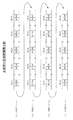
図1は、上記の送信側で構成されるマルチフレームの構成例を概略的に示したものである。同図には、位相情報をパスオーバヘッドのJ1バイト及びF2バイトに分割挿入することにより4段のマルチフレームを構成した例が示されている。 FIG. 1 schematically shows a configuration example of a multiframe configured on the transmission side. This figure shows an example in which a four-stage multi-frame is configured by dividing and inserting phase information into J1 byte and F2 byte of path overhead.
なお、同図では4段のマルチフレームが構成されているが、パスオーバヘッドの少なくとも2バイト(例えばJ1バイトとF2バイト)を使用すれば、少なくとも2段のマルチフレームを構成することが出来る。 In the figure, a four-stage multiframe is configured. However, if at least two bytes (for example, J1 byte and F2 byte) of the path overhead are used, at least a two-stage multiframe can be configured.
同図(1)に示す如く、マルチフレームの1段目では、フレームのJ1バイトには位相情報として"00"〜"63"までの値が順次分割挿入されており、F2バイトには位相情報として1段目を示す"00"の値がそれぞれ挿入されている。 As shown in (1) of the figure, in the first stage of the multi-frame, values from "00" to "63" are sequentially inserted into the J1 byte of the frame as phase information, and the phase information is stored in the F2 byte. As shown, the value “00” indicating the first row is inserted.
同図(2)〜(4)はそれぞれ、2〜4段目の各J1バイト及びF2バイトの位相情報の挿入状態を示しており、J1バイトについては同図(1)と同様であるが、F2バイトについては、段数が増える毎に"01"〜"03"までカウントアップされた値が挿入されている。 (2) to (4) in the figure show the insertion state of the phase information of each J1 byte and F2 byte in the second to fourth stages, respectively, and the J1 byte is the same as (1) in the figure, For the F2 byte, a value counted up from “01” to “03” is inserted every time the number of stages increases.
上記の送信側では、例えば同図に示したようなマルチフレームが構成された状態で伝送信号を現用系及び予備系の伝送路に分岐して伝送する。 On the transmission side, for example, the transmission signal is branched and transmitted to the transmission lines of the active system and the standby system in a state where the multiframe as shown in FIG.
一方、受信側では、現用系及び予備系の伝送路から伝送信号を受信するが、それぞれの伝送信号は伝送路の距離の差に起因して、同図に示したマルチフレームの位相がずれた状態になっている。例えば、或る時点で現用系及び予備系の伝送路から受信した伝送信号の位相情報であるJ1バイト及びF2バイトの組合せがそれぞれJ1="00",F2="00"及びJ1="01",F2="01"である場合には、予備系の伝送路から伝送信号の方が、単一フレームに換算して65フレームだけ位相が進んでいることになる。 On the other hand, on the receiving side, transmission signals are received from the transmission lines of the active system and the standby system. However, the transmission signals are shifted in the phase of the multiframe shown in FIG. It is in a state. For example, combinations of J1 byte and F2 byte, which are phase information of transmission signals received from the active and standby transmission lines at a certain point in time, are J1 = "00", F2 = "00", and J1 = "01", respectively. , F2 = "01", the phase of the transmission signal from the standby transmission path is advanced by 65 frames in terms of a single frame.
すなわち、J1バイト及びF2バイトの組合せによる位相情報に基づいて位相差を検出することが可能である。また、検出された位相差に基づく位相調整信号を現用系及び予備系のメモリに与えるため、同位相の状態で伝送信号をそれぞれ現用系及び予備系のメモリから出力することが出来る。 That is, it is possible to detect the phase difference based on the phase information based on the combination of the J1 byte and the F2 byte. Further, since the phase adjustment signal based on the detected phase difference is given to the active and standby memories, the transmission signal can be output from the active and standby memories in the same phase.
この場合、現用系及び予備系のメモリから出力される伝送信号は、同図のJ1バイトとF2バイトの値の組合せが一致するように位相調整された状態となる。上記の例では、現用系の伝送路から受信する伝送信号の位相情報がJ1="01",F2="01"となった時点で、現用系及び予備系のメモリから伝送信号が出力されることになる。 In this case, the transmission signals output from the active and standby memories are in a state where the phase is adjusted so that the combinations of the values of the J1 byte and the F2 byte in FIG. In the above example, when the phase information of the transmission signal received from the working transmission line becomes J1 = "01", F2 = "01", the transmission signal is output from the working and standby memories. It will be.
このように、現用系及び予備系のメモリからそれぞれ出力される伝送信号は位相が合った状態であるから、一方のメモリから他方のメモリへ出力の選択を切り替える際、無瞬断で行うことが可能になる。 In this way, the transmission signals output from the active and standby memories are in phase, so when switching the output from one memory to the other, it can be performed without interruption. It becomes possible.
この場合、パスオーバヘッドの1バイトのみで構成可能なマルチフレームの2倍以上長さのマルチフレーム(図1の例では4倍)に相当する位相差の吸収が可能になり、従来の例えばJ1バイトのみによる64マルチフレームでは困難であった経路長差が600kmを越える冗長構成の伝送路における無瞬断通信が可能になる。 In this case, it is possible to absorb a phase difference equivalent to a multiframe that is at least twice as long as a multiframe that can be configured with only one byte of path overhead (4 times in the example of FIG. 1), and for example the conventional J1 byte This makes it possible to perform uninterrupted communication over redundant transmission lines with path length differences exceeding 600 km, which was difficult with 64 multiframes.
また、同図のJ1バイトのみに注目すると、従来の64マルチフレームと同じであることから、上位互換性を実現することが可能になる。 If attention is paid only to the J1 byte in the figure, it is the same as the conventional 64-multiframe, so it is possible to realize upward compatibility.
上記の該所定バイトは少なくともJ1バイトとF2バイトとを含み、該マルチフレームは該J1バイトによる64マルチフレームを少なくとも該F2バイトによって特定可能な任意の段数集めて構成されていればよい。 The predetermined byte includes at least a J1 byte and an F2 byte, and the multiframe may be configured by collecting 64 multiframes based on the J1 byte by an arbitrary number of stages that can be specified by at least the F2 byte.
すなわち、該所定バイトはJ1バイト及びF2バイトを含むものであり、該F2バイトのみ又は該F2バイトと他のバイトとの組合せで特定可能な任意の段数だけ該J1バイトによる64マルチフレームを集めて該マルチフレームを構成する。 That is, the predetermined byte includes J1 byte and F2 byte, and 64 multiframes by the J1 byte are collected by an arbitrary number of stages that can be specified by only the F2 byte or a combination of the F2 byte and another byte. The multi-frame is configured.
これにより、従来の64マルチフレームの少なくとも2倍以上の位相差の吸収が可能になり、従来は困難であった経路長差が600kmを越える冗長構成の伝送路における無瞬断通信が可能になる。 This makes it possible to absorb a phase difference that is at least twice that of the conventional 64-multiframe, and enables uninterrupted communication over redundant transmission lines with a path length difference exceeding 600 km, which was difficult in the past. .
また、送信側で該段数の設定及び変更を行なうステップをさらに有してもよい。 Further, the transmission side may further include a step of setting and changing the number of stages.
すなわち、該段数は該F2バイトで有効にするビット数や他のバイトとの組合せ方法により様々な段数に特定することが可能であるため、該段数を設定及び変更するステップを有してもよい。これにより、現用系及び予備系の伝送路の距離の違いに応じて適切な段数のマルチフレームを構成することが可能となる。 That is, since the number of stages can be specified as various stages by the number of bits enabled in the F2 byte or a combination method with other bytes, a step of setting and changing the number of stages may be included. . As a result, it is possible to configure a multi-frame having an appropriate number of stages according to the difference in the distance between the active and standby transmission paths.
また、送信方法は、マルチフレームを構成するように伝送信号の各単一フレームのパスオーバヘッド中の少なくとも2つの所定バイトにそれぞれ順次位相情報を分割挿入するステップと、該伝送信号を現用系及び予備系の伝送路に分岐して伝送するステップと、を備えればよい。 In addition, the transmission method includes a step of sequentially inserting and inserting phase information into at least two predetermined bytes in the path overhead of each single frame of the transmission signal so as to constitute a multiframe, And branching to the transmission line of the system and transmitting.
さらに、受信方法は、現用系及び予備系の伝送路からそれぞれ受信した伝送信号の各単一フレームのパスオーバヘッド中の少なくとも2つの所定バイト毎に検出したマルチフレームの位相情報に基づき該現用系及び予備系の該伝送信号間の位相差を検出するステップと、該伝送信号をそれぞれ該現用系及び予備系のメモリに格納するステップと、該位相差に基づき位相調整信号を該現用系及び予備系のメモリに与えるステップと、該位相調整信号に基づき同位相の状態で該伝送信号を該現用系及び予備系のメモリからそれぞれ出力するステップと、該現用系及び予備系のメモリのいずれか一方から出力された該伝送信号を選択するステップと、を備えればよい。 Further, the reception method is based on multiframe phase information detected at least every two predetermined bytes in the path overhead of each single frame of transmission signals received from the transmission lines of the active system and the standby system, respectively. A step of detecting a phase difference between the transmission signals of the standby system, a step of storing the transmission signals in the memories of the active system and the standby system, respectively, and a phase adjustment signal based on the phase difference of the active system and the standby system A step of outputting the transmission signal in the same phase based on the phase adjustment signal from each of the working and standby memories, and Selecting the output transmission signal.
上記の無瞬断通信方法を実現する装置は、送信側で、マルチフレームを構成するように伝送信号の各単一フレームのパスオーバヘッド中の少なくとも2つの所定バイトにそれぞれ順次位相情報を分割挿入する位相情報挿入部と、該伝送信号を現用系及び予備系の伝送路に分岐して伝送する分配部と、受信側で、該現用系及び予備系の伝送路からそれぞれ受信した該伝送信号について該所定バイト毎に検出した該位相情報に基づき該現用系及び予備系の該伝送信号間の位相差を検出する位相差検出部と、該位相差に基づき該現用系及び予備系の位相調整信号を出力するメモリ制御部と、該現用系及び予備系の該伝送信号をそれぞれ格納した後、該位相調整信号に基づき同位相の状態で該伝送信号をそれぞれ出力する該現用系及び予備系のメモリと、該現用系及び予備系のメモリのいずれか一方から出力された該伝送信号を選択するセレクタと、を備えたことを特徴としている。 In the apparatus for realizing the non-instantaneous communication method, the transmission side sequentially divides and inserts phase information into at least two predetermined bytes in the path overhead of each single frame of the transmission signal so as to form a multi-frame on the transmission side. A phase information insertion unit; a distribution unit for branching and transmitting the transmission signal to the active and standby transmission lines; and a transmission side of the transmission signal received from the active and standby transmission lines on the receiving side. A phase difference detection unit that detects a phase difference between the transmission signals of the active system and the standby system based on the phase information detected for each predetermined byte; and a phase adjustment signal of the active system and the standby system based on the phase difference. A memory control unit for outputting, and a memory for the active system and the standby system for outputting the transmission signals in the same phase based on the phase adjustment signal after storing the transmission signals for the active system and the standby system, respectively. And a selector for selecting the transmission signal output from either one of the working system memory and the standby system memory.
この場合、所定バイトは少なくともJ1バイトとF2バイトとを含み、該マルチフレームは該J1バイトによる64マルチフレームを少なくとも該F2バイトによって特定可能な任意の段数集めて構成されていればよい。 In this case, the predetermined byte includes at least the J1 byte and the F2 byte, and the multiframe may be configured by collecting 64 multiframes based on the J1 byte by any number of stages that can be specified by the F2 byte.
上記の通信装置は、該送信側に該段数の設定及び変更を行なう手段をさらに設けてもよい。 The communication apparatus may further include means for setting and changing the number of stages on the transmission side.
また、上記の送信方法を実現する送信装置は、マルチフレームを構成するように伝送信号の各単一フレームのパスオーバヘッド中の少なくとも2つの所定バイトにそれぞれ順次位相情報を分割挿入する位相情報挿入部と、該伝送信号を現用系及び予備系の伝送路に分岐して伝送する分配部と、を備えればよい。 In addition, a transmission apparatus that realizes the above transmission method includes a phase information insertion unit that sequentially divides and inserts phase information into at least two predetermined bytes in the path overhead of each single frame of a transmission signal so as to form a multiframe. And a distribution unit for branching and transmitting the transmission signal to the active and standby transmission paths.
この場合、該所定バイトは少なくともJ1バイトとF2バイトとを含み、該位相情報挿入部は少なくとも該J1バイト及び該F2バイトに挿入する該位相情報としてそれぞれ第1及び第2のカウント値を与える第1及び第2の挿入カウンタと、該マルチフレームを構成するように該第1及び第2の挿入カウンタの動作を制御するカウンタ制御部とを有していればよい。 In this case, the predetermined byte includes at least a J1 byte and an F2 byte, and the phase information insertion unit provides first and second count values as the phase information to be inserted into at least the J1 byte and the F2 byte, respectively. It suffices to have the first and second insertion counters and a counter control unit that controls the operations of the first and second insertion counters so as to constitute the multiframe.
また、該第2の挿入カウンタの最大値を設定する設定部をさらに有してもよい。 Further, a setting unit for setting the maximum value of the second insertion counter may be further included.
また、上記の受信方法を実現する受信装置は、現用系及び予備系の伝送路からそれぞれ受信した伝送信号の各単一フレームのパスオーバヘッド中の少なくとも2つの所定バイト毎に検出したマルチフレームの位相情報に基づき該現用系及び予備系の該伝送信号間の位相差を検出する位相差検出部と、該位相差に基づき該現用系及び予備系の位相調整信号を出力するメモリ制御部と、該現用系及び予備系の該伝送信号をそれぞれ格納した後、該位相調整信号に基づき同位相の状態で該伝送信号をそれぞれ出力する該現用系及び予備系のメモリと、該現用系及び予備系のメモリのいずれか一方から出力された該伝送信号を選択するセレクタと、を備えればよい。 In addition, the receiving device that realizes the above receiving method includes a multi-frame phase detected at least every two predetermined bytes in the path overhead of each single frame of the transmission signal received from the transmission line of the active system and the protection system. A phase difference detection unit that detects a phase difference between the transmission signals of the active system and the standby system based on the information; a memory control unit that outputs a phase adjustment signal of the active system and the standby system based on the phase difference; and After storing the transmission signals of the active system and the standby system, respectively, the memories of the active system and the standby system that output the transmission signals in the same phase based on the phase adjustment signal, and the active system and the standby system And a selector that selects the transmission signal output from any one of the memories.
この場合、該所定バイトは少なくともJ1バイトとF2バイトとを含み、該位相差検出部は少なくとも該伝送信号の該J1バイト及び該F2バイトから該位相情報をそれぞれ第1及び第2のカウント値として検出する第1及び第2の検出カウンタと、該第1及び第2のカウンタ値に基づき該マルチフレームの位相情報を検出する第3の検出カウンタとをそれぞれ該現用系及び予備系に有してもよい。 In this case, the predetermined byte includes at least a J1 byte and an F2 byte, and the phase difference detection unit at least uses the phase information from the J1 byte and the F2 byte of the transmission signal as first and second count values, respectively. First and second detection counters for detection, and a third detection counter for detecting phase information of the multiframe based on the first and second counter values are provided in the active system and the standby system, respectively. Also good.
さらに、該F2バイトに該位相情報が挿入されていないことを該第2の検出カウンタが検出すると共に該第3の検出カウンタに通知したとき、該第3のカウンタは該第1のカウント値のみに基づき、該マルチフレームの位相情報を検出してもよい。 Further, when the second detection counter detects that the phase information is not inserted in the F2 byte and notifies the third detection counter, the third counter only detects the first count value. The phase information of the multiframe may be detected based on
本発明によれば、運用系と予備系の伝送路の経路長差が600kmを越えても無瞬断通信が可能になると共に、上位互換性を実現できる。 According to the present invention, non-instantaneous communication is possible even when the path length difference between the active and standby transmission lines exceeds 600 km, and upward compatibility can be realized.
図2は、本発明に係る送信装置の実施例として、送信装置100の構成例を示したものである。 FIG. 2 shows a configuration example of a transmission apparatus 100 as an embodiment of the transmission apparatus according to the present invention .
同図を図6に示した従来の送信装置10と比較して説明する。図2におけるインタフェース101、分配部107、0系インタフェース108、1系インタフェース109は、それぞれ、図6に示したインタフェース11、分配部15、0系インタフェース16、1系インタフェース17に相当するものである。
This figure will be described in comparison with the conventional transmission apparatus 10 shown in FIG. The
また、図2のオーバヘッド処理部102は、図6におけるPOH付加部12及びSOH付加部13を統合したものであるが、図6と同様に分割した構成とすることも出来る。
2 is an integration of the
また、図2の位相情報挿入部110は、図6の位相情報挿入部13に相当するものであるが、位相情報挿入部13がパスオーバヘッドのJ1バイトにのみ位相情報を挿入していたのに対し、位相情報挿入部110では、J1バイト及びF2バイトに位相情報を挿入するものである。 2 is equivalent to the phase information insertion unit 13 in FIG. 6, but the phase information insertion unit 13 inserted phase information only in the J1 byte of the path overhead. On the other hand, the phase information insertion unit 110 inserts phase information into the J1 byte and the F2 byte.
従って、図2に示す如く、位相情報挿入部110はJ1バイトに位相情報を入力するためのJ1マルチカウンタ103、F2バイトに位相情報を入力するためのF2マルチカウンタ104、及び両カウンタ103,104を制御するためのカウンタ制御部105を備えている。
Therefore, as shown in FIG. 2, the phase information insertion unit 110 controls the J1 multi-counter 103 for inputting phase information in the J1 byte, the F2 multi-counter 104 for inputting phase information in the F2 byte, and both
また、F2マルチカウンタ104によるマルチフレームの段数を設定するF2マルチ段数設定部106を備えているが、段数を固定にする場合はF2マルチ段数設定部106を備えなくてもよい。
Further, the F2 multistage
動作において、インタフェース101に入力された入力信号に対し、オーバヘッド処理部102においてパスオーバヘッド(POH)及びセクションオーバヘッド(SOH)を付加する。なお、セクションオーバヘッドの付加内容については図中省略してある。
In operation, the overhead processing unit 102 adds a path overhead (POH) and a section overhead (SOH) to the input signal input to the
同図に示す如く、カウンタ制御部105は、マルチフレームを構成するよう、J1マルチカウンタ103及びF2マルチカウンタ104を制御し、順次フレームのパスオーバヘッドのJ1バイト及びF2バイトに位相情報を挿入して行く。
As shown in the figure, the
このときに挿入されるJ1バイト及びF2バイトの具体例は、例えば、F2マルチ段数設定部106によってF2マルチカウンタ104のマルチ段数を"4"に設定している場合は、先に説明した図1のようなマルチフレーム構成になる。
Specific examples of the J1 byte and the F2 byte inserted at this time are, for example, when the F2 multistage
オーバヘッド処理部102からの出力信号は分配部107で分岐され、それぞれ0系インタフェース108及び1系インタフェース109を介して0系光伝送信号及び1系光伝送信号として伝送路に送出する。
The output signal from the overhead processing unit 102 is branched by the distribution unit 107 and sent to the transmission line as a 0-system optical transmission signal and a 1-system optical transmission signal via the 0-
図3は、本発明の受信装置の実施例として、上記の送信装置100に対向する受信装置200を示したものである。同図の受信装置200は、0系光伝送信号及び1系光伝送信号をそれぞれ受信する0系インタフェース201及び1系インタフェース211を有している。0系インタフェース201にはオーバヘッド処理部202及び0系メモリ203が順に接続されており、1系インタフェース211にはオーバヘッド処理部212及び1系メモリ213が順に接続されている。
FIG. 3 shows a receiving apparatus 200 facing the above transmitting apparatus 100 as an embodiment of the receiving apparatus of the present invention . The receiving apparatus 200 in the figure includes a 0-
0系メモリ203及び1系メモリ213には共通してセレクタ207が接続されている。
A
また、オーバヘッド処理部202には、各フレームのJ1バイト及びF2バイトをそれぞれ検出するJ1マルチカウンタ204及びF2マルチカウンタ205が接続されており、さらに、J1マルチカウンタ204及びF2マルチカウンタ205にはフレーム同期カウンタ206が接続されている。
The
同様に、オーバヘッド処理部212には、各フレームのJ1バイト及びF2バイトをそれぞれ検出するJ1マルチカウンタ214及びF2マルチカウンタ215が接続されており、さらに、J1マルチカウンタ214及びF2マルチカウンタ215にはフレーム同期カウンタ216が接続されている。
Similarly, the overhead processing unit 212 is connected to a
また、各フレーム同期カウンタ206及び216並びに0系メモリ203及び1系メモリ213に共通してメモリ制御部207が接続されている。
In addition, a
なお、J1マルチカウンタ204,214、F2マルチカウンタ205,215、及びフレーム同期カウンタ206,216は位相差検出部209を構成するものである。 The J1 multi-counters 204 and 214, the F2 multi-counters 205 and 215, and the frame synchronization counters 206 and 216 constitute the phase difference detection unit 209.
これにより、例えば図1に示したようなマルチフレームが構成された伝送信号を受信装置200が受信した場合、0系光伝送信号及び1系光伝送信号それぞれについてJ1バイト及びF2バイトの位相情報がJ1マルチカウンタ204,214及びF2マルチカウンタ205,215によって読み取られることになり、メモリ制御部207ではこの情報に応じた位相差を吸収すべく位相調整信号を0系メモリ203及び1系メモリ213に与えることにより、各メモリ203,213から出力される時点で伝送信号は同期している。
Thus, for example, when the receiving apparatus 200 receives a transmission signal in which a multiframe as shown in FIG. By being read by the J1 multi-counters 204 and 214 and the F2 multi-counters 205 and 215, the
従って、セレクタ208を高速に動作させることにより、無瞬断切替が実現できる。
Therefore, instantaneous switching can be realized by operating the
切替を行なう契機には、以下のようなものがある。
(1)伝送路故障、すなわちセクション区間やパス区間におけるエラーがあったとき。
(2)送信側の現用系又は予備系の送信部の故障があったとき。
(3)受信側の現用系又は予備系の受信部の故障があったとき。
(4)保守者による強制的な系変更指示等の装置制御による切替があったとき。
The triggers for switching include the following.
(1) When there is a transmission line failure, that is, an error in a section section or path section.
(2) When there is a failure in the transmission unit on the transmission side of the active or standby system.
(3) When there is a failure in the receiving unit on the receiving system.
(4) When there is a switch by device control such as a forced system change instruction by the maintenance person.
なお、F2バイトの値が常時全ビットが"1"であったり、"0"であったり、不定である場合には、F2マルチカウンタ205及び215がF2バイトの位相情報を検出できないことになる。この場合、F2マルチカウンタ205及び215がそれぞれアラーム信号をフレーム同期カウンタ206及び216に与えるようにし、フレーム同期カウンタ206及び216はJ1バイトの64マルチフレームに関する位相情報のみを用いるようにすれば、上位互換性が実現できる。すなわち、対向する送信装置が上記の図2に示した実施例の構成を有していない場合においても、少なくともJ1バイトによる64マルチフレーム同期は確立することが出来る。 If the value of the F2 byte is always “1”, “0”, or indefinite, the F2 multi-counters 205 and 215 cannot detect the phase information of the F2 byte. . In this case, if the F2 multi-counters 205 and 215 give alarm signals to the frame synchronization counters 206 and 216, respectively, and the frame synchronization counters 206 and 216 use only phase information about 64 multi-frames in the J1 byte, Compatibility can be realized. That is, even when the opposing transmission apparatus does not have the configuration of the embodiment shown in FIG. 2 above, at least 64 multiframe synchronization by the J1 byte can be established.
図4は、本発明の送信装置を、幹線伝送装置の送信側に適用した例を示したものである。同図に示した幹線伝送装置300の送信部400は、低速インタフェース部410及び高速インタフェース部420とで構成されており、低速インタフェース部410にはインタフェース盤411が搭載されている。また、高速インタフェース部420には、10G、2.5G、600M等の速度に応じて、それぞれ現用系及び予備系の高速インタフェース盤が搭載されている。すなわち、10Gインタフェース421,422、2.5Gインタフェース423,424、600Mインタフェース425,426が搭載されている。図中、各インタフェース421〜426の"(0)"及び"(1)"はそれぞれ0系及び1系の区別を示したものである。
FIG. 4 shows an example in which the transmission device of the present invention is applied to the transmission side of the trunk transmission device . The
なお、高速インタフェース部に搭載される高速インタフェース盤の速度は同図に示すものの他、SDHで定義されているあらゆる速度のものを使用することが出来る。 The speed of the high-speed interface board mounted on the high-speed interface section can be any speed defined in SDH, in addition to those shown in the figure.
クロスコネクト部430は、低速インタフェース部410と高速インタフェース部420とを接続するものであり、スイッチ制御部432によって時分割制御される0系時分割スイッチ431及び1系時分割スイッチ433によって構成されている。
The
この内、インタフェース盤411に、本発明の送信装置を適用している。すなわち、インタフェース盤411は、インタフェース部412、オーバヘッド処理部413、位相情報挿入部414、及び分配部415を備えており、位相情報挿入部414は、図2に示した位相情報挿入部110と同様な構成を有するものである。
Among these, the transmission device of the present invention is applied to the
図5は、本発明の受信装置を、幹線伝送装置の受信側に適用した例を示したものである。同図に示した幹線伝送装置300の送信部500は、低速インタフェース部510及び高速インタフェース部520とで構成されており、低速インタフェース部510にはインタフェース盤511が搭載されている。また、高速インタフェース部520には、10G、2.5G、600M等の速度に応じて、それぞれ現用系及び予備系の高速インタフェース盤が搭載されている。すなわち、10Gインタフェース521,522、2.5Gインタフェース523,524、600Mインタフェース525,526が搭載されている。
FIG. 5 shows an example in which the receiving apparatus of the present invention is applied to the receiving side of the trunk transmission apparatus . The
なお、図4に示した送信部400における各インタフェース421〜426と同様、各インタフェース521〜526の"(0)"及び"(1)"はそれぞれ0系及び1系の別を示したものであり、高速インタフェース盤は同図に示すものの他、SDHで定義されているあらゆる速度のものを使用することが出来る。
As with the
クロスコネクト部530は、低速インタフェース部510と高速インタフェース部520とを接続するものであり、スイッチ制御部532によって時分割制御される0系時分割スイッチ531及び1系時分割スイッチ533によって構成されている。
The
この内、インタフェース盤511に、本発明の受信装置を適用している。すなわち、インタフェース盤511は、オーバヘッド処理部517、519、0系メモリ514、1系メモリ516、位相差検出部518、メモリ制御部515、セレクタ513及びインタフェース512を備えており、位相差検出部518は、図3に示した位相差検出部209と同様の構成を有するものである。
(付記1)
送信側で、マルチフレームを構成するように伝送信号の各単一フレームのパスオーバヘッド中の少なくとも2つの所定バイトにそれぞれ順次位相情報を分割挿入するステップと、
該伝送信号を現用系及び予備系の伝送路に分岐して伝送するステップと、
受信側で、該現用系及び予備系の伝送路からそれぞれ受信した該伝送信号について該所定バイト毎に検出した該位相情報に基づき該現用系及び予備系の該伝送信号間の位相差を検出するステップと、
該伝送信号をそれぞれ該現用系及び予備系のメモリに格納するステップと、
該位相差に基づき位相調整信号を該現用系及び予備系のメモリに与えるステップと、
該位相調整信号に基づき同位相の状態で該伝送信号を該現用系及び予備系のメモリからそれぞれ出力するステップと、
該現用系及び予備系のメモリのいずれか一方から出力された該伝送信号を選択するステップと、
を備えたことを特徴とする通信方法。
(付記2)付記1において、
該所定バイトは少なくともJ1バイトとF2バイトとを含み、該マルチフレームは該J1バイトによる64マルチフレームを少なくとも該F2バイトによって特定可能な任意の段数集めて構成されていることを特徴とした通信方法。
(付記3)付記2において、
送信側で該段数の設定及び変更を行なうステップをさらに有することを特徴とした通信方法。
(付記4)
マルチフレームを構成するように伝送信号の各単一フレームのパスオーバヘッド中の少なくとも2つの所定バイトにそれぞれ順次位相情報を分割挿入するステップと、
該伝送信号を現用系及び予備系の伝送路に分岐して伝送するステップと、
を備えたことを特徴とする送信方法。
(付記5)
現用系及び予備系の伝送路からそれぞれ受信した伝送信号の各単一フレームのパスオーバヘッド中の少なくとも2つの所定バイト毎に検出したマルチフレームの位相情報に基づき該現用系及び予備系の該伝送信号間の位相差を検出するステップと、
該伝送信号をそれぞれ該現用系及び予備系のメモリに格納するステップと、
該位相差に基づき位相調整信号を該現用系及び予備系のメモリに与えるステップと、
該位相調整信号に基づき同位相の状態で該伝送信号を該現用系及び予備系のメモリからそれぞれ出力するステップと、
該現用系及び予備系のメモリのいずれか一方から出力された該伝送信号を選択するステップと、
を備えたことを特徴とする受信方法。
(付記6)
送信側で、マルチフレームを構成するように伝送信号の各単一フレームのパスオーバヘッド中の少なくとも2つの所定バイトにそれぞれ順次位相情報を分割挿入する位相情報挿入部と、
該伝送信号を現用系及び予備系の伝送路に分岐して伝送する分配部と、
受信側で、該現用系及び予備系の伝送路からそれぞれ受信した該伝送信号について該所定バイト毎に検出した該位相情報に基づき該現用系及び予備系の該伝送信号間の位相差を検出する位相差検出部と、
該位相差に基づき該現用系及び予備系の位相調整信号を出力するメモリ制御部と、
該現用系及び予備系の該伝送信号をそれぞれ格納した後、該位相調整信号に基づき同位相の状態で該伝送信号をそれぞれ出力する該現用系及び予備系のメモリと、
該現用系及び予備系のメモリのいずれか一方から出力された該伝送信号を選択するセレクタと、
を備えたことを特徴とする通信装置。
(付記7)付記6において、
該所定バイトは少なくともJ1バイトとF2バイトとを含み、該マルチフレームは該J1バイトによる64マルチフレームを少なくとも該F2バイトによって特定可能な任意の段数集めて構成されていることを特徴とした通信装置。
(付記8)付記7において、
該送信側に該段数の設定及び変更を行なう手段をさらに設けたことを特徴とした通信装置。
(付記9)
マルチフレームを構成するように伝送信号の各単一フレームのパスオーバヘッド中の少なくとも2つの所定バイトにそれぞれ順次位相情報を分割挿入する位相情報挿入部と、
該伝送信号を現用系及び予備系の伝送路に分岐して伝送する分配部と、
を備えたことを特徴とする送信装置。
(付記10)付記9において、
該所定バイトは少なくともJ1バイトとF2バイトとを含み、該位相情報挿入部は少なくとも該J1バイト及び該F2バイトに挿入する該位相情報としてそれぞれ第1及び第2のカウント値を与える第1及び第2の挿入カウンタと、該マルチフレームを構成するように該第1及び第2の挿入カウンタの動作を制御するカウンタ制御部とを有することを特徴とした送信装置。
(付記11)付記10において、
該第2の挿入カウンタの最大値を設定する設定部をさらに有することを特徴とした送信装置。
(付記12)
現用系及び予備系の伝送路からそれぞれ受信した伝送信号の各単一フレームのパスオーバヘッド中の少なくとも2つの所定バイト毎に検出したマルチフレームの位相情報に基づき該現用系及び予備系の該伝送信号間の位相差を検出する位相差検出部と、
該位相差に基づき該現用系及び予備系の位相調整信号を出力するメモリ制御部と、
該現用系及び予備系の該伝送信号をそれぞれ格納した後、該位相調整信号に基づき同位相の状態で該伝送信号をそれぞれ出力する該現用系及び予備系のメモリと、
該現用系及び予備系のメモリのいずれか一方から出力された該伝送信号を選択するセレクタと、
を備えたことを特徴とする受信装置。
(付記13)付記12において、
該所定バイトは少なくともJ1バイトとF2バイトとを含み、該位相差検出部は少なくとも該伝送信号の該J1バイト及び該F2バイトから該位相情報をそれぞれ第1及び第2のカウント値として検出する第1及び第2の検出カウンタと、該第1及び第2のカウンタ値に基づき該マルチフレームの位相情報を検出する第3の検出カウンタとをそれぞれ該現用系及び予備系に有することを特徴とした受信装置。
(付記14)付記13において、
該F2バイトに該位相情報が挿入されていないことを該第2の検出カウンタが検出すると共に該第3の検出カウンタに通知したとき、該第3のカウンタは該第1のカウント値のみに基づき、該マルチフレームの位相情報を検出することを特徴とした受信装置。
Among these, the receiving apparatus of the present invention is applied to the
(Appendix 1)
On the transmission side, dividing and inserting phase information sequentially into at least two predetermined bytes in the path overhead of each single frame of the transmission signal so as to constitute a multi-frame,
Branching and transmitting the transmission signal to the active and standby transmission paths;
On the receiving side, a phase difference between the transmission signals of the active system and the standby system is detected based on the phase information detected for each predetermined byte for the transmission signals respectively received from the transmission lines of the active system and the standby system. Steps,
Storing the transmission signals in the active and standby memories respectively;
Providing a phase adjustment signal to the active and standby memories based on the phase difference;
Outputting the transmission signal in the same phase based on the phase adjustment signal from the active and standby memories, respectively;
Selecting the transmission signal output from one of the working and standby memories;
A communication method comprising:
(Appendix 2) In
The predetermined byte includes at least a J1 byte and an F2 byte, and the multiframe is configured by collecting 64 multiframes based on the J1 byte and collecting any number of stages that can be specified by at least the F2 byte. .
(Appendix 3) In
A communication method further comprising a step of setting and changing the number of stages on a transmission side.
(Appendix 4)
Dividing and inserting phase information sequentially into at least two predetermined bytes in the path overhead of each single frame of the transmission signal so as to form a multiframe;
Branching and transmitting the transmission signal to the active and standby transmission paths;
A transmission method characterized by comprising:
(Appendix 5)
The transmission signals of the working system and the protection system based on the phase information of the multiframe detected at least every two predetermined bytes in the path overhead of each single frame of the transmission signal received from the transmission lines of the working system and the protection system, respectively. Detecting a phase difference between,
Storing the transmission signals in the active and standby memories respectively;
Providing a phase adjustment signal to the active and standby memories based on the phase difference;
Outputting the transmission signal in the same phase based on the phase adjustment signal from the active and standby memories, respectively;
Selecting the transmission signal output from one of the working and standby memories;
A receiving method comprising:
(Appendix 6)
On the transmission side, a phase information insertion unit that sequentially divides and inserts phase information into at least two predetermined bytes in the path overhead of each single frame of the transmission signal so as to form a multiframe,
A distribution unit for branching and transmitting the transmission signal to the transmission line of the active system and the standby system;
On the receiving side, a phase difference between the transmission signals of the active system and the standby system is detected based on the phase information detected for each predetermined byte for the transmission signals respectively received from the transmission lines of the active system and the standby system. A phase difference detector;
A memory control unit for outputting phase adjustment signals of the active system and the standby system based on the phase difference;
After storing the transmission signals of the active system and the standby system, respectively, the memories of the active system and the standby system that respectively output the transmission signals in the same phase based on the phase adjustment signal;
A selector for selecting the transmission signal output from one of the active and standby memories;
A communication apparatus comprising:
(Appendix 7) In Appendix 6,
The predetermined byte includes at least a J1 byte and an F2 byte, and the multiframe is configured by collecting 64 multiframes based on the J1 byte by collecting any number of stages that can be specified by at least the F2 byte. .
(Appendix 8) In Appendix 7,
A communication apparatus further comprising means for setting and changing the number of stages on the transmission side.
(Appendix 9)
A phase information insertion unit that sequentially inserts phase information into at least two predetermined bytes in the path overhead of each single frame of the transmission signal so as to form a multiframe;
A distribution unit for branching and transmitting the transmission signal to the transmission line of the active system and the standby system;
A transmission device comprising:
(Appendix 10) In Appendix 9,
The predetermined bytes include at least a J1 byte and an F2 byte, and the phase information insertion unit provides first and second count values as the phase information to be inserted into at least the J1 byte and the F2 byte, respectively. A transmission apparatus comprising: 2 insertion counters; and a counter control unit that controls operations of the first and second insertion counters so as to constitute the multiframe.
(Appendix 11) In Appendix 10,
A transmission apparatus further comprising a setting unit configured to set a maximum value of the second insertion counter.
(Appendix 12)
The transmission signals of the working system and the protection system based on the phase information of the multiframe detected at least every two predetermined bytes in the path overhead of each single frame of the transmission signal received from the transmission lines of the working system and the protection system, respectively. A phase difference detection unit for detecting a phase difference between;
A memory control unit for outputting phase adjustment signals of the active system and the standby system based on the phase difference;
After storing the transmission signals of the active system and the standby system, respectively, the memories of the active system and the standby system that respectively output the transmission signals in the same phase based on the phase adjustment signal;
A selector for selecting the transmission signal output from one of the active and standby memories;
A receiving apparatus comprising:
(Appendix 13) In
The predetermined byte includes at least a J1 byte and an F2 byte, and the phase difference detection unit detects the phase information from at least the J1 byte and the F2 byte of the transmission signal as first and second count values, respectively. The working system and the standby system have 1 and 2 detection counters and a 3rd detection counter that detects phase information of the multiframe based on the first and second counter values, respectively. Receiver device.
(Appendix 14) In Appendix 13,
When the second detection counter detects that the phase information is not inserted in the F2 byte and notifies the third detection counter, the third counter is based only on the first count value. A receiving apparatus for detecting phase information of the multiframe.
10, 100 送信装置
20, 200 受信装置
30〜90 伝送装置
300 幹線伝送装置
11, 29, 101, 412, 512 インタフェース
12 POH付加部
13, 110, 414 位相情報挿入部
14 SOH付加部
15, 107, 415 分配部
16, 21, 108, 201 0系インタフェース
17, 22, 109, 211 1系インタフェース
23, 24 マルチフレーム同期回路
25, 26 エラスティックメモリ
27 制御回路
28, 208, 513 セレクタ
102, 202, 212, 413, 517, 519 オーバヘッド処理部
103, 204, 214 J1マルチカウンタ
104, 205, 215 F2マルチカウンタ
105 カウンタ制御部
106 F2マルチ段数設定部
206, 216 フレーム同期カウンタ
203, 514 0系メモリ
213, 516 1系メモリ
207, 515 メモリ制御部
209, 528 位相差検出部
400 送信部
410, 510 低速インタフェース部
420, 520 高速インタフェース部
421〜426 高速インタフェース盤
430, 530 クロスコネクト部
431, 531 0系時分割スイッチ
432, 532 スイッチ制御部
433, 533 1系時分割スイッチ
500 受信部
図中、同一符号は同一又は相当部分を示す。
10, 100 Transmitter
20, 200 Receiver
30 ~ 90 Transmission equipment
300 Trunk transmission equipment
11, 29, 101, 412, 512 interface
12 POH addition section
13, 110, 414 Phase information insertion part
14 SOH addition part
15, 107, 415 Distribution section
16, 21, 108, 201 0 interface
17, 22, 109, 211 1 system interface
23, 24 Multi-frame synchronization circuit
25, 26 Elastic memory
27 Control circuit
28, 208, 513 selector
102, 202, 212, 413, 517, 519 Overhead processor
103, 204, 214 J1 multi counter
104, 205, 215 F2 multi counter
105 Counter control unit
106 F2 multistage setting section
206, 216 frame synchronization counter
203, 514 0 series memory
213, 516 1 system memory
207, 515 Memory controller
209, 528 Phase difference detector
400 Transmitter
410, 510 Low speed interface
420, 520 High-speed interface
421 to 426 High-speed interface panel
430, 530 Cross-connect section
431, 531 0 system time division switch
432, 532 Switch controller
433, 533 1 time division switch
500 Receiving part In the figure, the same reference numerals indicate the same or corresponding parts.
Claims (5)
該伝送信号を現用系及び予備系の伝送路に分岐して伝送するステップと、
受信側で、該現用系及び予備系の伝送路からそれぞれ受信した該伝送信号について該所定バイト毎に検出した該位相情報に基づき該現用系及び予備系の該伝送信号間の位相差を検出するステップと、
該伝送信号をそれぞれ該現用系及び予備系のメモリに格納するステップと、
該位相差に基づき位相調整信号を該現用系及び予備系のメモリに与えるステップと、
該位相調整信号に基づき同位相の状態で該伝送信号を該現用系及び予備系のメモリからそれぞれ出力するステップと、
該現用系及び予備系のメモリのいずれか一方から出力された該伝送信号を選択するステップと、
を備えたことを特徴とする通信方法。 On the transmission side, dividing and inserting phase information sequentially into at least two predetermined bytes in the path overhead of each single frame of the transmission signal so as to constitute a multi-frame,
Branching and transmitting the transmission signal to the active and standby transmission paths;
On the receiving side, a phase difference between the transmission signals of the active system and the standby system is detected based on the phase information detected for each predetermined byte for the transmission signals respectively received from the transmission lines of the active system and the standby system. Steps,
Storing the transmission signals in the active and standby memories respectively;
Providing a phase adjustment signal to the active and standby memories based on the phase difference;
Outputting the transmission signal in the same phase based on the phase adjustment signal from the active and standby memories, respectively;
Selecting the transmission signal output from one of the working and standby memories;
A communication method comprising:
該伝送信号を現用系及び予備系の伝送路に分岐して伝送する分配部と、
受信側で、該現用系及び予備系の伝送路からそれぞれ受信した該伝送信号について該所定バイト毎に検出した該位相情報に基づき該現用系及び予備系の該伝送信号間の位相差を検出する位相差検出部と、
該位相差に基づき該現用系及び予備系の位相調整信号を出力するメモリ制御部と、
該現用系及び予備系の該伝送信号をそれぞれ格納した後、該位相調整信号に基づき同位相の状態で該伝送信号をそれぞれ出力する該現用系及び予備系のメモリと、
該現用系及び予備系のメモリのいずれか一方から出力された該伝送信号を選択するセレクタと、
を備えたことを特徴とする通信装置。 On the transmission side, a phase information insertion unit that sequentially divides and inserts phase information into at least two predetermined bytes in the path overhead of each single frame of the transmission signal so as to form a multiframe,
A distribution unit for branching and transmitting the transmission signal to the transmission line of the active system and the standby system;
On the receiving side, a phase difference between the transmission signals of the active system and the standby system is detected based on the phase information detected for each predetermined byte for the transmission signals respectively received from the transmission lines of the active system and the standby system. A phase difference detector;
A memory control unit for outputting phase adjustment signals of the active system and the standby system based on the phase difference;
After storing the transmission signals of the active system and the standby system, respectively, the memories of the active system and the standby system that respectively output the transmission signals in the same phase based on the phase adjustment signal;
A selector for selecting the transmission signal output from one of the active and standby memories;
A communication apparatus comprising:
該所定バイトは少なくともJ1バイトとF2バイトとを含み、該マルチフレームは該J1バイトによる64マルチフレームを少なくとも該F2バイトによって特定可能な任意の段数集めて構成されていることを特徴とした通信装置。 In claim 2,
The predetermined byte includes at least a J1 byte and an F2 byte, and the multiframe is configured by collecting 64 multiframes based on the J1 byte by collecting any number of stages that can be specified by at least the F2 byte. .
該伝送信号を現用系及び予備系の伝送路に分岐して伝送する分配部と、
を備えたことを特徴とする送信装置。 A phase information insertion unit that sequentially inserts phase information into at least two predetermined bytes in the path overhead of each single frame of the transmission signal so as to form a multiframe;
A distribution unit for branching and transmitting the transmission signal to the transmission line of the active system and the standby system;
A transmission device comprising:
該位相差に基づき該現用系及び予備系の位相調整信号を出力するメモリ制御部と、
該現用系及び予備系の該伝送信号をそれぞれ格納した後、該位相調整信号に基づき同位相の状態で該伝送信号をそれぞれ出力する該現用系及び予備系のメモリと、
該現用系及び予備系のメモリのいずれか一方から出力された該伝送信号を選択するセレクタと、
を備えたことを特徴とする受信装置。 The transmission signals of the working system and the protection system based on the phase information of the multiframe detected at least every two predetermined bytes in the path overhead of each single frame of the transmission signal received from the transmission lines of the working system and the protection system, respectively. A phase difference detection unit for detecting a phase difference between;
A memory control unit for outputting phase adjustment signals of the active system and the standby system based on the phase difference;
After storing the transmission signals of the active system and the standby system, respectively, the memories of the active system and the standby system that respectively output the transmission signals in the same phase based on the phase adjustment signal;
A selector for selecting the transmission signal output from one of the active and standby memories;
A receiving apparatus comprising:
Priority Applications (2)
| Application Number | Priority Date | Filing Date | Title |
|---|---|---|---|
| JP2004054439A JP4312080B2 (en) | 2004-02-27 | 2004-02-27 | Communication method and apparatus |
| US10/873,148 US20050201277A1 (en) | 2004-02-27 | 2004-06-23 | Communication method and apparatus |
Applications Claiming Priority (1)
| Application Number | Priority Date | Filing Date | Title |
|---|---|---|---|
| JP2004054439A JP4312080B2 (en) | 2004-02-27 | 2004-02-27 | Communication method and apparatus |
Publications (2)
| Publication Number | Publication Date |
|---|---|
| JP2005244806A JP2005244806A (en) | 2005-09-08 |
| JP4312080B2 true JP4312080B2 (en) | 2009-08-12 |
Family
ID=34917902
Family Applications (1)
| Application Number | Title | Priority Date | Filing Date |
|---|---|---|---|
| JP2004054439A Expired - Fee Related JP4312080B2 (en) | 2004-02-27 | 2004-02-27 | Communication method and apparatus |
Country Status (2)
| Country | Link |
|---|---|
| US (1) | US20050201277A1 (en) |
| JP (1) | JP4312080B2 (en) |
Families Citing this family (3)
| Publication number | Priority date | Publication date | Assignee | Title |
|---|---|---|---|---|
| JP5103900B2 (en) * | 2006-12-28 | 2012-12-19 | 富士通株式会社 | Path status monitoring method and apparatus |
| US20090034475A1 (en) * | 2007-07-17 | 2009-02-05 | Viasat, Inc. | Soft Handoff Using A Multi-Beam Antenna System |
| JP2010130152A (en) * | 2008-11-26 | 2010-06-10 | Fujitsu Ltd | Transmission system, transmission apparatus, and method of controlling transmission system |
Family Cites Families (6)
| Publication number | Priority date | Publication date | Assignee | Title |
|---|---|---|---|---|
| DE4108429A1 (en) * | 1991-03-15 | 1992-09-17 | Philips Patentverwaltung | TRANSMISSION SYSTEM FOR THE DIGITAL SYNCHRONOUS HIERARCHY |
| JP3859268B2 (en) * | 1996-07-11 | 2006-12-20 | 富士通株式会社 | Pointer processing apparatus in SDH transmission system |
| JPH11266218A (en) * | 1998-03-17 | 1999-09-28 | Fujitsu Ltd | Phase control device and phase control method |
| US6195330B1 (en) * | 1998-11-05 | 2001-02-27 | David C. Sawey | Method and system for hit-less switching |
| JP2003188845A (en) * | 2001-12-17 | 2003-07-04 | Fujitsu Ltd | Path control method for receiving circuit and transmitting circuit |
| CA2420151C (en) * | 2002-03-01 | 2006-05-09 | Nippon Telegraph And Telephone Corporation | Hitless switching system and transmission apparatus |
-
2004
- 2004-02-27 JP JP2004054439A patent/JP4312080B2/en not_active Expired - Fee Related
- 2004-06-23 US US10/873,148 patent/US20050201277A1/en not_active Abandoned
Also Published As
| Publication number | Publication date |
|---|---|
| US20050201277A1 (en) | 2005-09-15 |
| JP2005244806A (en) | 2005-09-08 |
Similar Documents
| Publication | Publication Date | Title |
|---|---|---|
| EP1261157A2 (en) | Hitless protection switching | |
| US7606224B2 (en) | Transmission apparatus for making ring switching at SONET/SDH and RPR levels | |
| US6917584B2 (en) | Channel reassignment method and circuit for implementing the same | |
| JP3442180B2 (en) | Add-drop multiplex equipment | |
| US7224706B2 (en) | Hitless re-routing in composite switches | |
| US20050141569A1 (en) | Semi-transparent time division multiplexer/demultiplexer | |
| US6349092B1 (en) | BLSR node extension | |
| US8068518B2 (en) | Method and device for virtual concatenation transmission | |
| JP2001177491A (en) | Optical transmission system, synchronous multiplex transmission system, and synchronous multiplex transmission method | |
| JP2988440B2 (en) | Terminal equipment | |
| JP4312080B2 (en) | Communication method and apparatus | |
| US7526197B2 (en) | Utilizing the protecting bandwidth in a SONET network | |
| US6801548B1 (en) | Channel ordering for communication signals split for matrix switching | |
| JP3233332B2 (en) | Transmission equipment | |
| US7161965B2 (en) | Add/drop multiplexor with aggregate serializer/deserializers | |
| JP3976693B2 (en) | Non-instantaneous switching system | |
| GB2334186A (en) | SDH transmission systems | |
| US7110424B2 (en) | Bi-directional serializer/deserializer with discretionary loop-back | |
| US6735197B1 (en) | Concatenation detection across multiple chips | |
| US6856629B1 (en) | Fixed algorithm for concatenation wiring | |
| US7660308B2 (en) | Transmission apparatus | |
| JPH08223130A (en) | Switching without interruption | |
| KR0179505B1 (en) | Frame Aligner for TUI Signals for Slow Switching | |
| JP3716840B2 (en) | Non-instantaneous switching system and transmission device | |
| JP4231598B2 (en) | VC path non-instantaneous switching method and apparatus |
Legal Events
| Date | Code | Title | Description |
|---|---|---|---|
| A621 | Written request for application examination |
Free format text: JAPANESE INTERMEDIATE CODE: A621 Effective date: 20070208 |
|
| A977 | Report on retrieval |
Free format text: JAPANESE INTERMEDIATE CODE: A971007 Effective date: 20090501 |
|
| TRDD | Decision of grant or rejection written | ||
| A01 | Written decision to grant a patent or to grant a registration (utility model) |
Free format text: JAPANESE INTERMEDIATE CODE: A01 Effective date: 20090512 |
|
| A01 | Written decision to grant a patent or to grant a registration (utility model) |
Free format text: JAPANESE INTERMEDIATE CODE: A01 |
|
| A61 | First payment of annual fees (during grant procedure) |
Free format text: JAPANESE INTERMEDIATE CODE: A61 Effective date: 20090512 |
|
| FPAY | Renewal fee payment (event date is renewal date of database) |
Free format text: PAYMENT UNTIL: 20120522 Year of fee payment: 3 |
|
| R150 | Certificate of patent or registration of utility model |
Free format text: JAPANESE INTERMEDIATE CODE: R150 |
|
| LAPS | Cancellation because of no payment of annual fees |