JP4306810B2 - Film source video detection - Google Patents
Film source video detection Download PDFInfo
- Publication number
- JP4306810B2 JP4306810B2 JP52252299A JP52252299A JP4306810B2 JP 4306810 B2 JP4306810 B2 JP 4306810B2 JP 52252299 A JP52252299 A JP 52252299A JP 52252299 A JP52252299 A JP 52252299A JP 4306810 B2 JP4306810 B2 JP 4306810B2
- Authority
- JP
- Japan
- Prior art keywords
- field
- motion
- signal
- value
- detector
- Prior art date
- Legal status (The legal status is an assumption and is not a legal conclusion. Google has not performed a legal analysis and makes no representation as to the accuracy of the status listed.)
- Expired - Lifetime
Links
- 238000001514 detection method Methods 0.000 title claims description 25
- 230000033001 locomotion Effects 0.000 claims description 314
- 230000007704 transition Effects 0.000 claims description 65
- 238000000034 method Methods 0.000 claims description 15
- 230000003111 delayed effect Effects 0.000 claims description 10
- 230000004044 response Effects 0.000 claims description 3
- 230000006872 improvement Effects 0.000 claims description 2
- 238000004590 computer program Methods 0.000 claims 1
- 230000009191 jumping Effects 0.000 claims 1
- 241001646071 Prioneris Species 0.000 description 69
- 238000010586 diagram Methods 0.000 description 15
- 239000000463 material Substances 0.000 description 12
- 238000012545 processing Methods 0.000 description 7
- 238000006243 chemical reaction Methods 0.000 description 6
- 230000000750 progressive effect Effects 0.000 description 6
- 230000000694 effects Effects 0.000 description 5
- 230000006870 function Effects 0.000 description 5
- 230000015654 memory Effects 0.000 description 5
- 238000001914 filtration Methods 0.000 description 4
- 238000004364 calculation method Methods 0.000 description 3
- 230000000295 complement effect Effects 0.000 description 3
- 238000007906 compression Methods 0.000 description 3
- 230000006835 compression Effects 0.000 description 3
- 230000009471 action Effects 0.000 description 2
- 230000015572 biosynthetic process Effects 0.000 description 2
- 238000005259 measurement Methods 0.000 description 2
- 230000008520 organization Effects 0.000 description 2
- 230000037361 pathway Effects 0.000 description 2
- 238000003786 synthesis reaction Methods 0.000 description 2
- 238000012795 verification Methods 0.000 description 2
- 238000012935 Averaging Methods 0.000 description 1
- 239000000969 carrier Substances 0.000 description 1
- 238000013144 data compression Methods 0.000 description 1
- 230000006837 decompression Effects 0.000 description 1
- 230000001934 delay Effects 0.000 description 1
- 238000003708 edge detection Methods 0.000 description 1
- 230000008569 process Effects 0.000 description 1
- 230000003252 repetitive effect Effects 0.000 description 1
- 230000035945 sensitivity Effects 0.000 description 1
- 238000001228 spectrum Methods 0.000 description 1
- 230000001360 synchronised effect Effects 0.000 description 1
- 230000000007 visual effect Effects 0.000 description 1
Images


Classifications
-
- H—ELECTRICITY
- H04—ELECTRIC COMMUNICATION TECHNIQUE
- H04N—PICTORIAL COMMUNICATION, e.g. TELEVISION
- H04N7/00—Television systems
- H04N7/01—Conversion of standards, e.g. involving analogue television standards or digital television standards processed at pixel level
- H04N7/0112—Conversion of standards, e.g. involving analogue television standards or digital television standards processed at pixel level one of the standards corresponding to a cinematograph film standard
- H04N7/0115—Conversion of standards, e.g. involving analogue television standards or digital television standards processed at pixel level one of the standards corresponding to a cinematograph film standard with details on the detection of a particular field or frame pattern in the incoming video signal, e.g. 3:2 pull-down pattern
-
- H—ELECTRICITY
- H04—ELECTRIC COMMUNICATION TECHNIQUE
- H04N—PICTORIAL COMMUNICATION, e.g. TELEVISION
- H04N7/00—Television systems
- H04N7/01—Conversion of standards, e.g. involving analogue television standards or digital television standards processed at pixel level
- H04N7/0117—Conversion of standards, e.g. involving analogue television standards or digital television standards processed at pixel level involving conversion of the spatial resolution of the incoming video signal
- H04N7/012—Conversion between an interlaced and a progressive signal
Landscapes
- Engineering & Computer Science (AREA)
- Multimedia (AREA)
- Signal Processing (AREA)
- Computer Graphics (AREA)
- Television Systems (AREA)
- Picture Signal Circuits (AREA)
Description
技術分野
この発明はテレビジョン信号処理に関する。特に、この発明は、改良された信号処理装置と、テレビジョン信号において動画フィルムソースを検出することとに関する。
背景技術
米国特許第4,876,976号によると、60HzのNTSCテレビジョン信号がそのソースとして24フレーム/秒の動画フィルムを有すると検出されることが公知である。24フレーム/秒のフィルムは、3つの映像フィールドが1つのフィルムフレームから生じ、後の2つの映像フィールドが次のフィルムフレームから生じる(たとえば、AABBBCCDDDEE等、ここで「A」、「B」等は継続するフィルムフレームである)ような3−2フィルムプルダウン比を用いることによって、60HzのNTSC映像に与えられ、それと同期される。隣接する映像フレームにおける同じパリティの映像フィールドが比較される。動きが存在すると、映像ソースがフィルムである場合にのみ特徴的な反復パターンが得られる(すなわち、1101111011等、ここで「1」が動きのあることを示し、「0」が動きがないことを示す)。
米国特許第4,982,280号は、60Hzの順次走査される非飛越しテレビジョンシステムにおいて、ビデオカメラまたはフィルムであってもよい、30Hzの順次走査ソースを検出するための配置を開示している。30Hzの順次走査された映像イメージシーケンス内にフレームからフレームへの動きが存在する場合に、隣接する映像フィールドの映像シーケンスが比較されると、たとえば010101のパターンが生じ、30Hzの順次走査ソースを示す。111111等のパターンを生むための1秒おきの映像フィールドの比較によって30Hzの順次走査ソースがさらに確認される。動作するために、この配置は順次走査テレビジョン信号のフィールドの継続した同一対におけるピクセルの空間的な一致に頼る。
公開国際特許出願WO94/30006は、PAL、SECAM、50HzNTSC、50HzHDTVおよび50Hz白黒テレビジョン信号のような50Hzテレビジョン信号において毎秒25フレームの動画フィルムソースを検出するための装置を開示している。この検出方式は一方ではあるフィールドと前のフィールドとの間での動きの差を探し、他方ではその同じフィールドと後のフィールドとの間の動きの差を探す。
テレビジョン信号における動画フィルムソースの検出はさまざまな環境、たとえば、走査線倍増器、テレビジョン標準方式変換器、テレビジョンスローモーション処理装置および映像情報圧縮器において有益である。
周知の「走査線倍増」技術は、走査線の時間的に連続するインターリーブされた2フィールドがフレームを表わす(NTSC、PALおよびSECAMシステムにおいて用いられるような)飛越しテレビジョン信号を、フレームにおける全走査線が順次走査される非飛越しまたは順次走査テレビジョン信号に変換することを採用する。NTSCの場合の結果として、262.5本の走査線ではなく525本の走査線が60分の1秒ごとに提示され、こうして垂直解像度を525本の走査線の完全なフレーム解像度まで倍増し得る。典型的に、走査線倍増器は垂直解像度を完全に倍増するフィールド合成またはフィールド間補間を少なくとも一部の時間において採用する。フィールドの対が単一の順次思走査フレームを形成するために組合せられる。このような配置は米国特許第4,876,956号、第4,967,271号、第4,982,280号、第4,989,090号、第5,159,451号および第5,291,280号に説明される。
フィルム合成から生じる問題の1つは飛越しテレビジョン信号においてフィールド間に時間差があるということである。したがって、動く物体がフィールドからフィールドの間で異なる場所に存在することがあり、このような2フィールドが単一のフレームを形成するために組合せられれば水平または斜め方向に動く物体の垂直方向および斜め方向のエッジが滑らかな曲線ではなくギザギザした鋸波として現われる。走査線倍増はこのような遷移に沿って失われる。鋸波効果は再生システムが垂直エンハンスメントを用いる場合に悪化する。鋸波パターンは、異なるフィルムフレームから生じる2フィールドの不適当なインターリーブによって引起されるアーチファクトである。視覚的には、連続した垂直または斜め方向の線であるべきものがエッジ上のジグザグとして見える。
この問題に対する解決法の1つは、動きが起こっているテレビジョン画像ディスプレイの領域においてある種の走査線またはフィールド内補間を用いることである。動きを有する画像の領域においてフィールド内補間を与えるための改良された技術は上述の米国特許第4,989,090号に記載される。
切換可能フィールド間/フィールド内補間走査線倍増器の起こり得る問題は、動きが常には適切に検出されないかもしれず、上述のギザギザした垂直または斜め方向の遷移のアーチファクトを短時間および断続的に出現させることである。このような配置において、データ圧縮または(たとえばPALからNTSCへの)標準方式変換を受けた飛越しテレビジョン信号に対して動作するときに、動作方式を正確に一貫して切換えることは特に困難であるかもしれない。
この問題に対する別の公知の解決法は、いつ飛越しテレビジョン信号のソースが動画フィルムであるかを認識することである。上述のように、米国では、毎秒24フレームの動画フィルムが「3−2プルダウン比」によって毎秒30フレームのNTSCテレビジョン信号に与えられ、したがって、3フィルムフレーム、2フィルムフレーム、3フィルムフレーム等のパターン化されたシーケンスが隣接するテレビジョンフィールドによって運ばれる。同じフィルムフレームを運ぶ飛越しフィールドの対を特定することによって、その対は、各々動画フレームを表わす本質的に完全な走査線倍増された順次走査フレームを発生するよう合成され得る。このような技術は上述の米国特許第4,876,596号、第4,982,280号および第5,291,280号に説明される。
しかしながら、動画フィルム検出配置にも問題がある。たとえば、(フィルム編集ではなく)映像編集が3−2プルダウン比を混乱させ、合成されたテレビジョンフィールドを異なるフィルムフレームから引出させるかもしれない。このように、フィルムプルダウン比検出回路がそれ自体再同期するまで(典型的には入力された飛越しテレビジョン信号の1から4フィールド)、上述のギザギザした鋸波遷移アーチファクトが動く物体のエッジに出現し得る。望ましくない効果は一瞬であるが、これは目に見えるものであり、時にはその他の点ではほぼ完全な走査線倍増配置を混乱させる。
最後に述べる問題も、入力された飛越しテレビジョン信号がフィルムソースから映像ソースへとフェードするときに動画フィルムソース走査線倍増配置において生じる。この場合、たとえば上述の米国特許第4,982,280号に説明されるようなシステムが、3−2プルダウンパターンの損失を認めて上述の種類のフィールド間/フィールド内補間配列に切換えるまで、数フィールドにわたってその「フィルムモード」で動作し続ける。フィルムモードの動作から転換するまでのこれら数フィールドの間に、フィールド間に動きがあれば同様のギザギザした鋸波アーチファクトが発生し得る。さらに、動画ソースから引出される飛越しテレビジョン信号が不完全にデータ圧縮または標準方式変換されている場合にも問題が起こり得る。
3−2プルダウン比を混乱させる映像編集の問題に対する解決法の1つは上述の米国特許第5,291,280号に記載される。この解決法はフィールド動き検出器を用い、映像編集のために「先を見越す」ための回路を含む。しかしながら、この発明のさまざまな局面に関して説明するように、上述のような走査線倍増器および他の応用において用いるためのよりよいフィルム動き検出器を提供することがなお必要であるような欠点が上述の5,291,280特許および他の先行技術に存在する。
発明の開示
この発明は多数の局面を有し、すなわち、低周波遷移を動きとして扱わない改良されたフィールド動き検出器と、動きを副搬送波信号成分から区別する向上した能力を有するフレーム動き検出器と、鋸波アーチファクト検出器と、アーチファクト検出器が、フィルムパターンの中断にしか反応しない場合よりも早くフィルムモードからフィルムパターン検出器を取出すことができるようにフィルムパターン検出器と組合せられた鋸波アーチファクト検出器と、改良されたフィールドベースフィルム検出器と、フィールドの終わりの計算を行なうことによって動作するフィルム検出器およびそれとともに用いられる動き検出器と、フレーム動き検出器がフィールド動き検出器によって検証のために用いられる動き信号を与えるようなフィールド動き検出器およびフレーム動き検出器の組合せと、最小数のNTSCフィルムパターンシーケンスを必要とする改良されたNTSCフィルム検出器と、最小の動きしきい値検出器を用いる改良されたPALフィルム検出器と、これらさまざまな局面の組合せと、1つ以上のこれらのさまざまな局面を組入れる走査線倍増器(飛越し−順次走査変換器)とを有する。
【図面の簡単な説明】
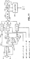
図1は、さまざまな局面を含む、この発明の全体図を示す機能ブロック図である。
図2は、それぞれのフィールド内の相対的なピクセル位置を示す、3つの隣接する飛越し走査テレビジョンフィールドの疑似三次元図である。
図3は、この発明またはその局面が用いられ得る飛越し−走査線倍増順次走査変換器環境を示す機能ブロック図である。
図4は、図1のフィールド動き検出器の詳細を示す機能ブロック図である。
図5A−Fは、動きなしで高周波(鋭い)垂直遷移を有する、先行技術のフィールド動き検出器の場合のための映像ストリームにおけるピクセル振幅を示す一連の理想化された図である。
図6A−Fは、動きありで高周波(鋭い)垂直遷移を有する、先行技術のフィールド動き検出器の場合のための映像ストリームにおけるピクセル振幅を示す一連の理想化された図である。
図7A−Fは、動きなしで低周波(広い)垂直遷移を有する、先行技術のフィールド動き検出器の場合のための映像ストリームにおけるピクセル振幅を示す一連の理想化された図である。
図8A−Hは、動きなしで高周波(鋭い)垂直遷移を有する、この発明の局面に従うフィールド動き検出器の場合のための映像ストリームにおけるピクセル振幅を示す一連の理想化された図である。
図9A−Hは、動きありで高周波(鋭い)垂直遷移を有する、この発明の局面に従うフィールド動き検出器の場合のための映像ストリームにおけるピクセル振幅を示す一連の理想化された図である。
図10A−Hは、動きなしで低周波(広い)垂直遷移を有する、この発明の局面に従うフィールド動き検出器の場合のための映像ストリームにおけるピクセル振幅を示す一連の理想化された図である。
図11は、図1のフレーム動き検出器の詳細を示す機能ブロック図である。
図12は、図1のNTSCフィルム検出器の詳細を示す機能ブロック図である。
図13は、図1のPALフィルム検出器の詳細を示す機能ブロック図である。
図14は、図1の鋸波検出器の詳細を示す機能ブロック図である。
図15A−Dは、適当にインターリーブされた走査線と不適当にインターリーブされた走査線との理想化された図であり、不適当にインターリーブされた走査線が鋸波アーチファクトを示す。
図16は、図1の鋸波ベース編集検出器の詳細を示す機能ブロック図である。
発明を実施するための形態
ここに特に明記しない限り、この発明の実際の実施例はアナログ、(ソフトウェアでのデジタル信号処理を含む)デジタル、またはハイブリッドアナログ/デジタル技術を用いて実現され得る。ほとんどの状況においてアナログ実現例とデジタル実現例とが等価であることは当業者には周知である。
この明細書を通じて、簡略化のために、信号入力および信号出力は単一点として描かれ、信号を搬送する線は単一線として描かれる。実際問題として、2つ以上の入力点または出力点と2つ以上の信号搬送線とが、信号のフォーマットと、この発明の実際の実施例が物理的に構成される態様とに依存して必要とされることが理解される。
別個に示された機能が全体的または部分的に他のものと結合され得ることも理解されるべきである。さらに、当業者は実際問題として、さまざまな図に示すスイッチが機械的ではなく電子的またはソフトウェア的に実現されることを理解するであろう。
この発明またはその局面は、たとえば映像データ圧縮器または標準方式変換器に先行する飛越し−走査線倍増順次走査変換器と関連して有利に用いられ得る。映像圧縮および標準方式変換の両方は、飛越しテレビジョン信号ではなく順次走査テレビジョン信号において動作する際により正確かつより簡単に行なわれる。このような映像圧縮または標準方式変換に先行する順次走査変換器においてこの発明を用いることによって、このプロセスはより最適な信号ソースに対して動作することを確実とされる。
そのさまざまな局面を含む、この発明の全体図を図1に示す。後述する図3は、この発明またはその局面が用いられ得る飛越し−走査線倍増順次走査変換器を示す。
ここで図1を参照すると、信号Yinがフィールド・ラインメモリ102のアレイに与えられる。信号Yinは白黒映像信号であってもよく、コンポーネントカラー映像信号の輝度成分であってもよい。当業者は、コンポーネント映像信号が(輝度およびクロミナンス(色)成分がそこから抽出され得る)RGB、Y/I/Q、Y/U/V、Y/R−Y/B−Y、Y/Cr/Cb等のようなアナログまたはデジタル成分を含んでもよいことを理解するであろう。さらに、デジタル成分の場合、受信されたデジタルコンポーネント映像信号は多数の圧縮または非圧縮フォーマットのうちのどのようなものであってもよく、このフォーマットはたとえば、CCIR(国際無線通信諮問委員会)(たとえば、CCIR推奨601の下でのデジタル映像符号化フォーマットの階層、4:2:2フォーマットがしばしばCCIR601映像信号と呼ばれる)、ISO/MPEG(国際標準化機構のモーション・ピクチャー・エキスパート・グループ)、SMPTE(映画テレビ技術者協会)、EBU(ヨーロッパ放送連合)の推奨、規格または圧縮アルゴリズム、および/または他の業界、政府または準政府組織の推奨または規格に従うデジタルコンポーネント映像フォーマットのさまざまなものを含む。
メモリ102のアレイはYinの時間遅延されたものからなる5つの出力を与え、これはYin自体とともに入力輝度信号の6つの時間的に間隔をあけられた信号、すなわち、第1のテレビジョンフィールドF0における2信号、第2のテレビジョンF1における2信号、および第3のテレビジョンフィールドF2における2信号を与える。
3つの隣接するフィールドにおけるピクセル(テレビジョン画素)の空間位置に関する6つの信号ストリームの時間間隔は、図2を参照するとよりよく理解されるかもしれない。図2は擬似三次元図であり、縦軸が、走査線に対して垂直な、テレビジョン画像フィールドの垂直方向であり、横軸が、走査線に対して平行な、テレビジョン画像フィールドの水平方向であり、かつ各フィールドの面に対して垂直な方向が各隣接フィールドが別個の時間で示される擬似時間軸であるように、垂直および水平の次元がテレビジョン画像フィールドの面において定められている。テレビジョンフィールドの活性画像情報の間のある任意の時間に、ピクセルがフィールドF0において、P(F0−1H)として表わされ得る。このピクセルは水平走査線における点として図2に示される。後の時間に生じる、フィールドF0における第2のピクセル、ピクセルPF0は垂直方向にピクセルP(F0ー1H)の真下にあり、次のより低い水平走査線における点として示される。ピクセルP(F0)の262線分(NTSCの場合、PALでは312線)後に生じる、フィールドF1における第1のピクセルと、ピクセルP(F0)の263線分(NTSCの場合、PALでは313線)後に生じる、フィールドF1における第2のピクセルとは、それぞれピクセルP(F1−1/2H)およびピクセルP(F1+1/2H)と称される。第1の水平走査線における点として示されるピクセルP(F1−1/2H)は垂直方向にピクセルP(F1+1/2H)の真上にあり、ピクセルP(F1+1/2H)は次のより低い水平走査線における点として示される。フィールドF0のピクセルP(F0)がある場所と空間的に対応する、フィールドF1における点P(F1)は、フィールドからフィールドへの水平走査線の飛越しオフセットのためにピクセルP(F1−1/2H)とピクセルP(F1+1/2H)との間の中間点である。このように、ピクセルP(F1−1/2H)は点P(F1)から2分の1線分の時間だけ先行し、ピクセルP(F1+1/2H)は2分の1線分の時間だけ点P(F1)の後にある。F0およびF1に対応するフィールドF2の空間点はピクセルP(F0)の525線分、ちょうど1フレームまたは2フィールド分後に生じるピクセルP(F2)の場所である。ピクセルP(F2)はフィールドF2における水平走査線における点として示される。1水平走査線分だけ時間的に早く生じる、フィールドF2における第2のピクセル、P(F2−1H)はピクセルP(F0)を含む走査線の真上の水平走査線における点として示される。
ここで、フィールド・ラインメモリ102のアレイの詳細が示される図1を再び参照すると、遅延しない入力輝度信号ストリームYin自体がF0−1H出力ストリームを与える。入力輝度信号ストリームYinは第1の1H(1水平線時間)遅延素子104に与えられてF0出力ストリームを生じる。遅延素子104の出力はまた第1のnH遅延素子106(ここで、nはNTSCでは262線であり、PALでは312線である)に与えられてF1−1/2H出力ストリームを生じる。遅延素子106の出力はさらなる1H遅延素子108に与えられてF1+1/2H出力ストリームを生じ、さらなるnH遅延素子110(ここで、nはNTSCでは262線であり、PALでは312線である)に与えられてF2−1H出力ストリームを生じる。遅延素子110の出力はまたさらなる1H遅延素子112に与えられてF2出力ストリームを生じる。これら遅延素子は、当業者には周知のさまざまなハードウェア、ソフトウェアおよびハイブリッドハードウェア/ソフトウェア技術によって実現され得る。遅延素子は直列遅延素子として示されるが、これらは、信号ストリームが1回読込まれ、多数回読出されるマルチポートランダムアクセスメモリ、または他の等価な方法のような他の方法で実現されてもよい。
このように、メモリ102のアレイは、隣接する3フィールドの各々に2つというように、6つのピクセル位置に対応する6つの信号出力ストリーム、すなわち、フィールドF0における時間位置F0−1HおよびF0のピクセルと、フィールドF1における時間位置F1−1/2HおよびF1+1/2Hのピクセルと、フィールド2における時間位置F2−1HおよびF2のピクセルとを与える。
後述のフィールド動き検出器114が、1フィールド−2分の1線分、および1フィールド+2分の1線分だけ時間的に間隔をあけられた信号であるF0、F1−1/2HおよびF1+1/2H信号ストリームを受取る。このような入力をフィールド動き検出器に与えることは公知である。たとえば米国特許第4,982,280号および第5,291,280号を参照されたい。フィールド動き検出器の目的は、垂直方向の遷移が起こるときに(たとえば、ある水平線の下の画像部分が黒であり、その線上の画像部分が白であるとき、またはその反対のときに)動きを誤って検出せずに飛越しフィールドから飛越しフィールドへの(たとえば1フィールド当り2分の1線よりも高い速度を有する)動きを検出することである。上述の5,291,280特許に開示されるタイプのフィールド動き検出器がこの発明の局面で採用され得るが、この発明の一局面をなす後述の改良されたフィールド動き検出器を用いることが好ましい。なぜなら、この改良されたフィールド動き検出器はあるタイプの垂直方向遷移によって引起される誤った検出に対する抵抗がより大きいためである。4,982,280特許のもののようなフィールド動き検出器がこの発明の局面で用いられ得るが、上述の5,291,280特許のフィールド動き検出器の方が4,982,280特許のものより好ましく、これはより先の特許が垂直方向の遷移から生じる誤った検出を避けることができないためである。フィールド動き検出器114の出力F0mtnは、各々以下に説明される、NTSCフィルム検出器118およびPALフィルム検出器120に与えられる。
ここで、下の第2のフィールド動き検出器(図示せず)が、これもまた1フィールド−2分の1線分、および1フィールド+2分の1線分だけ時間的に間隔をあけられた信号である、F2、F1−1/2HおよびF1+1/2H信号を受取ってもよい。このような第2のフィールド動き検出器がさらなる冗長性を与えるためまたは処理精度を高めるために用いられてもよい。
メモリ102のF0およびF2出力はフレーム動き検出器114に与えられ、そこでこの2信号はピクセルごとに比較される。フレーム動き検出器の出力「MOTIN」は後述のNTSCフィルム検出器118、PALフィルム検出器120および鋸波ベース編集検出器126に与えられる。MOTION信号は図3に示すような飛越し−走査線倍増順次走査変換器の入力としても用いられ得る。F0およびF2信号ストリーム入力を受取るフレーム動き検出器は先行技術において公知である。たとえば、上述の米国特許第4,982,280号、第4,967,271号および第5,291,280号を参照されたい。上述の米国特許第4,982,280号、第4,967,271号および第5,291,280号の特許のものを含むさまざまなフレーム動き検出器がこの発明の局面においてフレーム動き検出器として用いられ得る。しかしながら、この発明の局面をなす後述の改良されたフレーム動き検出器を用いることが好ましい。
F0−1H、F0、F1−1HおよびF1+1H信号ストリームとF2、F2−1H、F1−1HおよびF1+1H信号ストリームとはそれぞれF0鋸波検出器128およびF2鋸波検出器130に与えられる。各鋸波検出器は、フィールド1およびフィールド0の不適当なインターリーブまたはフィールド1およびフィールド2の不適当なインターリーブが引起すであろうジグザクアーチファクトを探す。これら2つの検出器の出力F0sawおよびF2sawはそれぞれ鋸波ベース編集検出器126に与えられる。鋸波検出器は米国特許第5,625,421号に開示されている。この発明の局面をなす鋸波検出技術は、この発明の鋸波検出器が飛越し−順次変換の前の代わりに(走査線倍増後の)このような変換の後に動作するという点で上述の第5,625,421号におけるものとは異なる。
さらに後述するように、NTSCフィルム検出器およびPALフィルム検出器(それぞれ118および120)はフィールド0とフィールド1との間の累積したフィールド動きを検査してから、フィールド動きフィルムシーケンスパターン(NTSCでは「10100」のパターン、PALでは「10」のパターン)を探し、マテリアルがフィルムであって映像でないことを判断する。上述の4,982,280特許では、フィールドの代わりにフレームがフィルム検出器において比較される。4,982,280特許のフィルム検出器はピクセルの差を累積する代わりに最小サイズ制限を与える。それにもかかわらず、上述の4,982,280特許におけるようなステートマシンがこの発明のフィルム検出器において用いられ得る。フィルム検出器は「悪い編集」が検出されるときに編集Y/N(イエス/ノー)信号によってリセットされる。悪い編集とは、2つの完全なフィルムフレームがまだ取除かれていないときにフィルムマテリアル上の映像に行なわれた編集であって3−2プルダウン比が変更してしまうものを意味する。フィルムシーケンスは以下のように見えるかもしれない。
AAABBCCCDDEEEFF
良い編集は以下のように見えるかもしれない。
AAABBEEEFF
悪い編集は以下のように見えるかもしれない。
AAACCCDDEEEFF
ここで、A、B等は特定の動画フレーム(フレームA、B等)から引出された映像フィールドである。
フィルム検出器の出力はフィルムY/N(イエス/ノー)信号およびF0/F2信号の2信号である。フィルムY/Nは走査線倍増器(図3参照)がその下で機能するモードを選択する。F0/F2信号は、マテリアルがフィルムであるときに走査線倍増器(図3参照)がどちらかのフィールド信号ストリームF0またはF2をF1−1/2Hでインターリーブする(合成する)かを選択する。フィルムY/NおよびF0/F2信号は図3に示すような飛越し−走査線倍増順次走査変換器への入力として用いられ得る。
2つのフィルム検出器のうちの1つの出力が2回路2接点スイッチ132によって選択される。スイッチは外部から与えられるNTSC/PAL信号によって制御される。これは、入力された映像フォーマットに依存して活性状態であるべき適切なフィルム検出器を選択する。PALフィルム検出器はまたNTSC信号における30フレーム/秒のソースを検出するためにも用いられてもよく、この場合スイッチ132はPALスイッチ位置に配置される。
F0およびF2鋸波検出器(128および130)の出力F0sawおよびF2sawは、動き信号のフィルムY/N信号およびF0/F2信号とともに、鋸波ベース編集検出器126によって組合せられてフィルム検出器118および120をリセットするために用いられる編集Y/N信号を生じる。編集Y信号はフィルムY/N信号を直ちにNにリセットする。
ここで、この発明またはその局面が用いられ得る飛越し−走査線倍増順次走査変換器環境を示す図3を参照すると、入力信号Yin(Yinの性質については上の説明を参照されたい)が、図1の配置のさまざまな機能を含むブロック302に与えられる。ブロック302は、F0タイミングを有する第1の映像ストリームと、F1−1/2Hタイミング(すなわち、F0ストリームタイミングの公称1フィールド時間後)を有する第2の映像ストリームと、F2タイミングを有する第3の映像ストリームとを与える(ここで、F0、F1−1/2HおよびF2は図1および2に関連して説明されるとおりである)。F1−1/2H映像ストリームが「直接」フィールドYdirを走査線倍増器対304の一方の入力に与える。F0およびF2映像ストリームは非フィルム映像プロセッサ306およびフィルム映像プロセッサ308に与えられる。ブロック302はそのF0/F2出力をフィルム映像プロセッサ308に与え、そのフィルムY/N出力を1回路2接点スイッチ310の制御入力に与える。スイッチ310の出力は「補間された」フィールドYintを走査線倍増器対304の他方の入力に与える。走査線倍増器対304からの出力は組合せられて出力信号Youtを与える。
動作において、補間されたフィールドYintからの走査線が直接フィールドYdirからの走査線でインターリーブされる。補間されたフィールドの走査線は動画フィルムソースの場合はF0またはF2映像ストリームから取出され、ソースが動画フィルムでない場合は、フィールド内補間、フィールド間補間、フィールド内補間とフィールド間補間との組合せ、または何らかの他の公知の技術のようなさまざまな公知の技術の任意のものによって構成される。図3の例では、非フィルム映像プロセッサ306が、(たとえばF0とF2とを平均化することによって)動きなしまたは低度の動きの条件に対してはフィールド間補間を用い、中程度から高程度の動きの条件に対してはフィールド内補間を用いるように、与えられた動き信号に応答して適応して動作することを想定する。フィルム映像プロセッサはフィルムソースが検出されるときにF0/F2信号に応答してF0映像ストリームまたはF2映像ストリームのいずれかを選択し、正しいフィールドが直接フィールドと合成されることを確実とする。
フィールド動き検出器
図1のフィールド動き検出器の詳細を図4に示す。フィールド動き検出器は対向するフィールドパリティ(たとえば、フィールド0およびフィールド1)の一時的に隣接するピクセル情報を比較し、フィールドからフィールドへの動きを垂直方向の画像遷移から区別してフィールド動き信号を与える。
各フィールド動き検出器は3つの減算器(402、404および406)、小絶対値保持器408、大小比較器410および動き有無スイッチ412を含む。減算器402はF1−1/2H信号およびF0信号を受取る。減算器404はf0信号およびF1+1/2H信号を受取る。減算器406はF1−1/2H信号およびF1+1/2H信号を受取る。米国特許第5,291,280号に説明されるフィールド動き検出器(たとえば図3参照)は上述したのと同じ入力を受取る減算器402および404と小絶対値保持器408とを用いる。この発明のフィールド動き検出器は上述の5,291,280特許におけるのと同じ小絶対値保持器の配置を用いることができる。
フィールド間減算はフィールド動きを生じるが、また垂直方向の遷移を動きとして誤って検出する。小絶対値保持器は2つのフィールド間減算値のうち小さい方を選択し、それによって高周波垂直遷移を動きから区別する。残念ながら、低周波垂直遷移がなお動きとして検出される。この欠点を克服するために、この発明のフィールド動き検出器は、出力である垂直エネルギの測定値が大小比較器410において小絶対値保持器408の出力であるフィールド動きの測定値と比較されるシングルライン垂直差分器(第3の減算器406)を付加する。シングルライン垂直差分器として機能する減算器406はフィールド内の垂直遷移を探す。垂直遷移の大きさがフィールド動きの大きさよりも大きければ、垂直遷移は誤って動きであると判断され、出力スイッチがノー位置になり、動きが検出されなかった。しかしながら、フィールド動きが垂直エネルギよりも大きければ、動きの値イエスが出力される。これはより正確な動き検出を生む。ここで、減算器からの動き情報信号のサインは小絶対値保持器を考慮して無関係である。
この発明の改良されたフィールド動き検出器の性能と比較して先行技術のフィールド動き検出器が低周波垂直遷移と動きとを区別することができないことは、図5−10を参照することによってよりよく理解できる。図5−10は、さまざまな信号条件での時間間隔をあけられた映像ストリームにおける、時間に対する(隣接する線での)ピクセル振幅(すなわち、水平ピクセルではなく垂直ピクセル)と、結果として生じるフィールド動き検出器信号出力との理想化された図である。図5−7は(上述のようにこの発明の改良されたフィールド動き検出器の一部をなす)上述の5,291,280特許に開示されるような先行技術のフィールド動き検出器に関連し、図8−10はこの発明の改良されたフィールド動き検出器に関連する。図5−10を参照する際に、飛越し映像フィールドにおけるさまざまなピクセルの相対位置をより十分に認識するには図2を参照するとよい。
ここで図5(先行技術−高周波垂直遷移、動きなし)を参照すると、図5Aは映像ストリームF0における隣接する線のピクセル振幅を示し、図5Bは映像ストリームF1−1/2H(時間的にF0映像ストリームの262線分後)におけるピクセル振幅を示し、図5Cは映像ストリームF1+1/2H(時間的にF0映像ストリームの263線分後)におけるピクセル振幅値を示す。減算器402は図5Dに示す出力(1ピクセル)を生じ、減算器404は図5Eに示す出力(0ピクセル)を生じる。したがって、小絶対値保持器408は図5Fに示す出力(0ピクセル)を生じる。この出力、すなわち、上述の5,291,280特許のフィールド動き検出器によって与えられるであろう出力は正しい出力であり、動きがない場合の高周波遷移が各ピクセル位置に対して正しい「動きなし」出力を生む。
ここで図6(先行技術−高周波垂直遷移、動きあり)を参照すると、図6Aは映像ストリームF0における隣接する線のピクセル振幅を示し、図6Bは映像ストリームF1−1/2H(時間的にF0映像ストリームの262線分後)におけるピクセル振幅を示し、図6Cは映像ストリームF1+1/2H(時間的にF0映像ストリームの263線分後)におけるピクセル振幅値を示す。減算器402は図6Dに示す出力(2ピクセル)を生じ、減算器404は図6Eに示す出力(3ピクセル)を生じる。したがって、小絶対値保持器は図6Fに示す出力(2ピクセル)を生じる。この出力、すなわち、上述の5,291,280特許のフィールド動き検出器によって与えられるであろう出力は正しい出力であり、動きがある場合の高周波遷移が正しい「動き」出力(相対的なフィールドからフィールドへの動きの振幅を示す、2線におけるピクセル位置での動き信号)を生む。
ここで図7(先行技術−低周波遷移、動きなし)を参照すると、図7Aは映像ストリームF0における隣接する線のピクセル振幅を示し、図7Bは映像ストリームF1−1/2H(時間的にF0映像ストリームの262線分後)のピクセル振幅を示し、図7Cは映像ストリームF1+1/2H(時間的にF0映像ストリームの263線分後)のピクセル振幅値を示す。各々が低周波垂直遷移の場合(黒から白へのフェード)で起こるであろうようなゆっくりと増加するピクセル値を示す。減算器402は図7Dに示す出力(4低レベルピクセル)を生じ、減算器404は図7Eに示す出力(4低レベルピクセル)を示す。したがって、小絶対値保持器408は図7Fに示す出力(3低レベルピクセル)を生じる。図7Hに示すこの出力、すなわち、上述の5,291,280特許のフィールド動き検出器によって与えられるであろう出力は誤った出力であり、動きのない場合の低周波遷移が誤った「動き」出力(3線におけるピクセル位置での低振幅動き信号)を生む。
ここで図8(この発明−高周波垂直遷移、動きなし)を参照すると、図8Aは映像ストリームF0における隣接する線のピクセル振幅を示し、図8Bは映像ストリームF1−1/2H(時間的にF0映像信号の262線分後)におけるピクセル振幅を示し、図8Cは映像ストリームF1+1/2H(時間的にF0映像ストリームの263線分後)におけるピクセル振幅値を示す。減算器402は図8Dに示す出力(1ピクセル)を生じ、減算器404は図8Eに示す出力(0ピクセル)を生じる。したがって、小絶対値保持器408は図8Fに示す出力(0ピクセル)を生じる。減算器406は図8Gに示す出力(1ピクセル)を生じる。垂直エネルギを示す減算器406の出力が小絶対値保持器408の出力よりも大きいので、大小比較器がスイッチ412をそのノーの位置になるようにさせ、出力はなく、動きなしを示す。図8Hに示す出力は先行技術と同じである(図5参照)。
ここで図9(この発明−高周波垂直遷移、動きあり)を参照すると、図9Aは映像ストリームF0における隣接する線のピクセル振幅を示し、図9Bは映像ストリームF1−1/2H(時間的にF0映像ストリームの262線分後)におけるピクセル振幅を示し、図9Cは映像ストリームF1+1/2H(時間的にF0映像ストリームの263線分後)におけるピクセル振幅値を示す。減算器402は図9Dに示す出力(2ピクセル)を生じ、減算器404は図9Eに示す出力(3ピクセル)を生じる。したがって、小絶対値保持器408は図9Fに示す出力(2ピクセル)を生じる。減算器406は図9Gに示す出力(1ピクセル)を生じる。垂直エネルギを示す減算器406の出力が小絶対値保持器408の出力よりも小さいので、大小比較器は2ピクセル分の時間の間スイッチ412をそのイエスの位置に移動させ、小絶対値保持出力がフィールド動き検出器の出力として与えられ、2ピクセル位置でこれらの振幅の動きがあることを示す。残りのピクセル位置では、減算器406の出力が小絶対値保持器408の出力よりも大きいので、大小比較器がスイッチ412をそのノーの位置にさせ、出力がなく動きなしを示す。図9Hに示す結果は先行技術と同じである(図6参照)。
ここで図10(この発明−低周波垂直遷移、動きなし)を参照すると、図10Aは映像ストリームF0におけるピクセル振幅を示し、図10Bは映像ストリームF1−1/2H(時間的にF0映像ストリームの262線分後)の隣接する線のピクセル振幅を示し、図10Cは映像ストリームF1+1/2H(時間的にF0映像ストリーム263線分後)におけるピクセル振幅値を示す。減算器402は図10Dに示す出力(4低レベルピクセル)を生じ、減算器404は図10Eに示す出力(これもまた4低レベルピクセル)を生じる。したがって、小絶対値保持器408は図10Fに示す出力(4低レベルピクセル)を生じる。減算器406は図10Gに示す出力(より高いレベルの4ピクセル)を生じる。垂直エネルギを示す減算器406の出力が小絶対値保持器408の出力よりも大きいので、大小比較器はスイッチをそのノーの位置に移動させ、出力はなく、動きなしが示される。図10Hに示す出力は正しく、先行技術とは異なる(図8参照)。したがって、この発明の改良されたフィールド動き検出器は、動きから高周波遷移を区別する先行技術の能力を維持しながらも、動きから低周波垂直遷移を区別する能力を加える。
フレーム動き検出器
図11に詳細に示すフレーム動き検出器124(図1)はF0映像ストリーム信号とF2映像ストリーム信号とをピクセルごとに比較して、フィールドF1における対応のピクセルが動きありの可能性があるかどうかを判断する。多くの先行技術のフレーム検出器がこの発明の局面で用いられ得るが、今から説明する改良されたフレーム動きが好ましい。
上述の米国特許第4,982,280号に説明されるフレーム動き検出器では、高周波動きがフィルタ処理されて取除かれる。この発明の局面を構成するフレーム動き検出器は動きと副搬送波信号成分とをより改良された態様で区別する。
この発明の一部をなす改良されたフレーム動き検出器では、フレーム減算が減算器1102においてF0とF2との間で行なわれる。減算器1102の出力は次に低域フィルタ1104および減算器1106によって生じる相補的な低域フィルタおよび高域フィルタを通る。デジタル実現例では、低域フィルタはカラー副搬送波周波数で0の5タップFIRフィルタであってもよい(NTSCおよびPALの両方で使用するためのフレーム検出器では、フィルタ特性はNTSC信号またはPAL信号のいずれが処理されているかによって切換可能であってもよい)。ライン1108上の(ほとんどの動きが存在する)水平低域フィルタ処理される経路は整流器1110において整流され、しきい値回路1112に与えられ、しきい値回路1112は動きLPFノイズしきい値を与えることによってノイズ成分を取除く。デジタル実現例では、しきい値回路1112はたとえば信号を(たとえば8ビットから)4ビットに制限できる。ライン1114上の水平高域フィルタ処理される経路は、減算器1116、加算器1118および(NTSCに対しては1線分の遅延を、PALでは2線分の遅延を与える)遅延素子1120によって構成される相補的な垂直低域フィルタおよび高域フィルタに入る。これらの経路、すなわち垂直HPF経路1122および垂直LPF経路1124は次に個々にそれぞれの整流器1126および1128において整流され、それら自体のしきい値回路を有する(それぞれ動きHHPF−VHPFノイズしきい値および動きHHPF−VLPFノイズしきい値を与えることによってノイズ成分を取除くしきい値回路1130および1132)(ここで、HHPFは水平高域フィルタ等である)。デジタル実現例では、しきい値回路1130および1132がそれぞれの信号を4ビットに制限できる。
このように、水平に低域フィルタ処理される(HLPF)経路と、水平に高域フィルタ処理され、垂直に高域フィルタ処理される(HHPF−VHPF)経路と、水平に高域フィルタ処理され、垂直に低域フィルタ処理される(HHPF−VLPF)経路との3つの経路が与えられる。この3つの経路の目的は真の動き情報からカラー副搬送波信号成分を分離することである。HLPF経路出力はLPF1104の水平低域フィルタ処理作用の結果として副搬送波信号成分を実質的に有さない。HLPF経路の補数を有する2つのHHPF経路はスペクトルの高周波部分に存在する副搬送波信号成分を低減するために垂直フィルタ処理を必要とする。このような成分は実際のテレビジョンスクリーンに起こり得る垂直線パターンの様相を有する。HHPF−VHPF経路のフィルタ処理作用は低振幅レベル副搬送波信号成分を通す。HHPF−VHPFしきい値を十分に高く設定することによって、真の動きが副搬送波成分から区別される。HHPF−VLPF経路のフィルタ処理作用は(線から線で位相が異なっているので垂直成分を有する)副搬送波成分を拒絶するが、動きとして検出されなければならない(「動くマルチバースト」と呼ばれる)線の水平に動くパターンを通す(このようなパターンは他の2つの経路によって拒絶される)。HHPF−VLPF経路はHHPF−VHPF経路よりも低いしきい値レベルを有し得る。なぜなら、HHPF−VLPF経路は振幅に基づいて望ましくない信号成分から望ましいものを区別しないためである。HLPFしきい値レベルおよびHHPF−VLPFしきい値レベルはノイズから免れるために選択される。
3つの異なってフィルタ処理された動き経路が次に加算器1134において組合せられ、伸長機1136において伸長させられる。好ましくは、これらは5ピクセル分水平に、1フィールド分一時的に、かつ1線分垂直に伸長させられる。このような水平、垂直および一時的伸長のための技術は公知である。たとえば、上述の米国特許第5,488,422号を参照されたい。ブロック1136の出力は大値保持器1138の第1の入力と262H/312H(NTSCでは262線、PALでは312線)遅延素子とに与えられ、その出力は第2の入力としてブロック1138に、また1H(1線)遅延素子1142に与えられ、その出力はブロック1138に第3の入力として与えられる。ブロック1136−1142は一時的かつ垂直に伸長された動き信号を与える。一時的かつ垂直に伸長させる目的は、急速に動く物体(たとえば、揺れるペンジュラム)がフレーム間に「ホール」を残す状況を防ぎ、NTSC信号の場合ではフィルムマテリアルがフィルムマテリアルとして検出されないときにシャープな画像とソフトな画像との間でむらが起こる様相を防ぐという2つである。また、伸長はフレーム動き信号がフィルム検出器においてフィルム動き信号を「取囲む」ことを確実とする。
フレーム動き検出器は動きLPFノイズしきい値、動きHHPF−VLPFノイズしきい値および動きHHPF−VHPFノイズしきい値との3つの調節可能なパラメータを有する。パラメータは、ノイズおよび副搬送波信号成分によって引起される動きの誤った検出を最小にするよう調節されるべきである。
フィルム検出器
機能上、NTSCフィルム検出器118はPALフィルム検出器120とは別個に設けられる。実際の実施例では、2つの検出器は回路および/または機能を共有することがありがちである。両方のフィルム検出器がフィルムパターンの開始を判断するという同じ目的を有し、(そのフィルムY/N信号をそのY(イエス)条件にすることによって示すように)フィルムモードに入り、フィルムモードに入った後フィルムパターンが崩れると(フィルムY/N信号をそのN(ノー)条件にすることによって示すように)フィルムモードから出る。異なるフィルムパターンは(NTSCにおける24フレーム/秒のフィルムソースおよびPALにおける25/フレーム秒のフレームソースから生じる)各映像フォーマット(NTSCまたはPAL)に固有のものである。両方のフィルム検出器が動作のある特性および原理を共有する。両方がフィールド動き検出器114のF0mtn出力と、フレーム動き検出器124の動き出力と、鋸波ベース編集検出器126からの編集Y/N信号とを受取る。一次入力はフィールド動き検出器のF0mtn信号である。フレーム動き信号はフィールド動き信号の検証を行なうものとして役立つ。編集Y/N信号は、フィルムパターンが崩れているという、鋸波アーチファクトを引起す信号条件の検出に基づいて初期の指示を与える。
NTSCテレビジョン信号において24フレーム/秒の動画ソースを検出するための先行技術の典型的なフィルム検出器(たとえば上述の4,982,280および5,291,280特許を参照)はフィールドベースというよりフレームベースである。しかしながら、PALテレビジョン信号において25フレーム秒の動きを検出するためのフィールドベースフィルム検出器は公開国際特許出願WO94/30006に開示されている。この発明のNTSCフィルム検出器およびPALフィルム検出器は上述の国際出願におけるフィールドベースPALフィルム検出器を改良したものである。したがって、たとえばNTSCのためのフレームベースフィルムパターンが0の後に4つの1が続く5フレームシーケンスである(周知のように、このパターンは動画ソースにおける動きの条件に対して生じ、動きなしはその1を0にさせるが、特定の0の位置はフィルムソースを保証するためにあらゆる条件下で0であり続けなければならない)。この発明の改良されたフィールドベース検出技術では、3つの0の位置があらゆるフィルム動き条件の下で5フィールドシーケンスにおいて0を維持しなければならず(2つの1の位置が1または0の条件を想定できる)、こうしてフィルムパターンの崩れをより高速に検出する。
さらに、このフィルム検出器は鋸波ベース編集検出器によって与えられる編集Y/N信号に応答し、これは、信号がそのY状態になると、フィルム検出器が直ちにフィルムモードから出て、検出器のフィルムY/N信号出力が直ちにNになるように行なわれる。編集Y信号はフィルムシーケンスパターンが崩れているというフィールド内の指示を与え、こうしてフィルムシーケンスパターン検出器(エラーを検出するのに少なくとも1フィールドを必要とするパターン検出器)がこのような判断を行なうことができる前に初期の指示を与える。こうして、編集Y/N信号はフィルムモードから出るための第2の方法(第1のものはフィルムパターンの中断)を与える。
フィルムベース編集検出では、シーケンスが崩れている(シーケンスAAABB122233−「鋸波検出器」の表題の下の説明を参照されたい)ので検出されないあるタイプの編集がある。全編集がフィールドベース検出において悪い編集として検出される(許容可能な1つの「良い」編集を除く−たとえば上の「良い編集」の例を参照されたい)。
NTSCフィルム検出器
NTSCフィルム検出器118(図1)はフィールド動き検出器114のF0mtn出力と、フレーム動き検出器124の動き出力と、鋸波ベース編集検出器からの編集Y/N信号とを受取る。NTSCフィルム検出器118はNTSCテレビジョン信号において24フレーム/秒のソースを探す。これはフィールド0とフィールド1との間の累積されたフィールド動きを検査してから、フィールド動きフィルムシーケンスパターン「10100」を探し、そのマテリアルがフィルムであって映像でないことを判断する。図12はNTSCフィルム検出器の詳細を示す。
NTSCフィルム検出器への一次入力はフィールド動き検出器114(図1)のF0mtn出力である。F0mtn信号は副搬送波残留物を取除くために低域フィルタ1202においてフィルタ処理され、整流器1204において整流され、フィルム動き帰線消去機1206によって帰線消去されて、いかなる画像エッジアーチファクトおよびサブタイトルも動きとして検出されないようにする。整流され、帰線消去された動き信号は次にノイズアーチファクトを低減するためにしきい値回路1208に与えられる。しきい値回路は固定されかつ予め規定されたフィルムノイズしきい値によってセットされる。平行経路において、フレーム動き検出器からの動き入力がしきい値回路1210によってデジタル形態で1ビット動きイエス/ノー信号にしきい値処理される。このしきい値回路は動きしきい値によってセットされる。1ビットの動きイエス/ノー信号は次に動き有無スイッチ1212を制御するために用いられる。フレーム動き指示はフィールド動き指示の検証に役立ち、所与のピクセルでフレーム動きがなければ同じピクセルに対してフィールド動きはあり得ない(フレーム動きは、フレーム動きの帯域がフィールド動きを取囲むことを確実とするように水平および垂直に伸長させられる)、スイッチ1212からの1ビットフィールド動き信号は次にフィールドレートアキュムレータ1214において全フィールドにわたって累積される。
各フィールドの終わりに、データがラッチされ、動き値が3つの平行な経路1216、1218および1220に渡される。これらは、1)5フィールド最小検出器1222(ただし5フィールド最小が安全マージンを満たすために設けられることが好ましく、3フィールド最小は実用的でない)への経路1216と、2)3フィールド重み平均計算機1224への経路1218と、3)フィールドの終わり計算が行なわれる減算器1226の一方の側への経路1220とである。各フィールドの初めにアキュムレータがリセットされる。
フィールド動きが正確ではないので、動きのないフィールドがそれと関連した非ゼロ値を有するかもしれない。5フィールド最小検出器1222は最小の動きを求めて5つの隣接するフィールドを検査する。動きのないフィールドが常にある5つの隣接するフィールドのフィルムでは、したがって最小の動き値がそれに対応する。この出力は、経路1220上のアキュムレータ1214の出力から動きのないフィールドと関連したベース動き値を取除くために減算器1226への他の入力を与える。減算器1226の出力は次に、ブロック1224の出力、すなわち3つのフィールドの重み平均によってしきい値が決定される可変しきい値回路1228に渡される。
動きしきい値は画像情報の動きに依存するので、ほとんど動きのない画像情報は動きの多いマテリアルよりも低いしきい値を有する。最小動き検出器1222および重み平均計算機1224は小さい動きのあるシーン上でのフィルム検出の感度を大いに高め、ナイキスト基準に反するコンピュータ発生マテリアルをファクタ出力する。動きのあるフィールドでは「1」であり、動きのないフィールドでは「0」である可変しきい値回路1228の出力が次に、循環するシーケンス10100を探すステートマシン1230に与えられる。ステートマシン1230は上述の4,982,280特許に説明されるタイプのものであってもよい。検出されるフィルムシーケンスの数がフィルムシーケンス獲得数に一旦達すれば、フィルムモードが活性化される。フィルムシーケンス獲得数、すなわち、フィルムシーケンスの検出を示すためにパターンが繰返さなくてはならない回数がシステム設計者によって設定される。たとえば、この数はNTSCでは3であってもよく(ただし1で十分かもしれない)、あまり固有のフィルムパターンを有さないPALでは5または6であってもよい。
ビデオモードへの遷移は、1)フィルムシーケンスが「1」で置き換えられる「0」によって中断される場合(フィルムモードでは一度動きのないフィールドの場合のように「1」フィールドが「0」フィールドで置き換えられ得るが、動きのないフィールドは動きのあるものへと転換され得ないことに注目されたい)、または2)編集Y/N信号がハイ(イエス)になる場合の2つの条件のいずれかで起こる。
この発明のNTSCフィルム検出器がフィールドベースであるので、悪い編集がフィルム検出器をフィルムモードから出させることができる場所は5フィールドシーケンス内に3つある。これに対して、フレーム動きフィルム検出方式ではその場所は1つである−0111。上述のように、「0」は「1」になることができないが「1」は「0」となることができ、したがってフィールド動きシーケンスは、フレームベースフィルムシーケンス上の1つの「0」に対して、編集検出器として用いられ得る3つの「0」を有する。これは悪い編集の負の視覚的影響を最小にする効果を有する。
NTSCフィルム検出器は、フィルムノイズしきい値と、動きしきい値と、NTSCフィルムシーケンス獲得数と、エッジ効果を最小にするためにフィルム動き検出の領域を規定する4つのフィルム帰線消去パラメータとの7つのパラメータを有し、4つのフィルム帰線消去パラメータは、フィルム帰線消去トップラインと、フィルム帰線消去ボトムラインと、フィルム帰線消去右側と、フィルム帰線消去左側とを有する。
PALフィルム検出器
PALフィルム検出器120(図1)はPALテレビジョン信号において25フレーム/秒のソースを探し、これはまたNTSCテレビジョン信号において30フレーム/秒のソースを探すことができる。これはフィールド0とフィールド1との間の累積されたフィールド動きを検査し、フィールド動きフィルムシーケンスパターン「10」を探し、その後マテリアルがフィルムであってビデオでないかを判断する。PALフィルム検出器の詳細を図13に示す。
PALフィルム検出器は図12のNTSCフィルム検出器118(図1)と同じF0フィルム動き信号F0mthをその入力で受取り、同じピクセルレート処理を行なう。実際問題として、低域フィルタ1202、整流器1204、帰線消去回路1206、ノイズしきい値回路1208、動きしきい値回路1210、動き有無スイッチ1212およびフィールドレートアキュムレータ1214はNTSCフィルム検出器とPALフィルム検出器との間で共通である。PALフィルム検出器において対応する素子には対応の「13xx」の参照番号が割当てられる。図12のNTSCフィルム検出器と関連して説明される共通の素子は繰返し説明されない。
PALで行なわれるフィールドの終わり計算は、NTSCで検出されるシーケンスがPALで検出されるものと異なるので、NTSCとは異なる。PALの循環するフィルムシーケンスは「10」である。このシーケンスは連続して数フレームにわたって映像マテリアル上に起こり得るので、この場合を区別するために注意を払わなくてはならない。まず、フィールドレートアキュムレータ1314からの現在のフィールド動き(B)が、フィールドレートアキュムレータ1314の出力を1フィールド遅延素子1342において遅延させる(これは垂直同期信号によってフィールドレートでクロックされるフリップフロップとして行なわれ得る)ことによって引出されたすぐ前のフィールド動き(A)と比較器1340において大きさを比較されて、比較器1340の出力で動きサイン信号を形成する。現在の値が前の動き値よりも大きければ「1」が出力され、逆に現在の値が前の動きよりも小さいかそれと等しければ「0」が出力される。
平行経路で、現在のフィールド動き(B)とすぐ前のフィールド動き(A)との2つの動きが演算子1344によって変更されて割合|(A−B)/[(A+B)/2]|を形成する。平均値によって割算される差の絶対値であるこの関数が隣接するフィールドの動き割合に対応し、これは次に、その出力が動きサイン信号でANDゲート1348においてゲーティング処理されるしきい値回路1346に渡される。最小の動き制約を導入することが必要とされ、これは動きサイン信号がAとBとの間の差が1であるかまたは1000であるかを考慮しないためである。映像マテリアルでは、1000、1410、1400および1510のような動き値を得ることは稀ではない。これらは動きサイン信号−フィルム状パターンから「0101」を生じる。小さい動きフィルムソースは6、100、5、110のような値を有するかもしれない。このように、PAL最小動き割合はフィルムと映像とを区別するのに役立つ。代替的であるがあまり望ましくない態様で、フィールドレートアキュムレータ(図12の1214、図13の1314)と、ステートマシン(図12の1230、図13の1350)との間のNTSCフィルム検出器の配置が用いられてもよい。
最小の動き割合制約が適えられれば、動きサインはPALフィルムステートマシン1350に与えられ、これは上述の4,982,280特許におけるのと同じタイプのステートマシンであってもよい。制約が適えられなければ0が入力される。PALフィルムモードはフィルムシーケンスの数がPALフィルムシーケンス獲得数に達すると入力される。
NTSCの場合のように、映像モードへの遷移は、1)フィルムシーケンスが中断される場合かまたは2)編集Y/N信号がハイになる場合の2つの条件のうちのいずれかで起こる。ルックアップテーブルがそれぞれの映像規格に対して適切に用いられるならば、単一フィルムステートマシンがNTSCフィルム検出器およびPALフィルム検出器のために用いられてもよいことに注意されるべきである。
NTSCフィルム検出器と同様、PALフィルム検出器は、フィルムノイズしきい値と、動きしきい値と、PALフィルムシーケンス獲得数と、PAL最小動き割合と、フィルム動き検出の領域を規定する4つのフィルム帰線消去パラメータとの8つの調節可能なパラメータを有し、4つのフィルム帰線消去パラメータは、フィルム帰線消去トップラインと、フィルム帰線消去ボトムラインと、フィルム帰線消去右側と、フィルム帰線消去左側とを有する。
鋸波検出器
鋸波検出器128および130(図1)はF1とf0とのまたはF1とF2との不適当なインターリーブが生じる「鋸波」アーチファクトを探す。鋸波検出器の詳細を図14に示す。
鋸波は、同様の垂直内容を有する偶数番目の線と同様の垂直内容を有する奇数番目の線とによって特徴付けられ、奇数番目の線は図15A−15Dに示すように偶数の線から水平にオフセットされている。鋸波アーチファクトについては上述の5,625,421特許でさらに説明される。図15Aは線が適当にインターリーブされた場合の垂直バーの表示された外観を示す。図15Bは線が不適当にインターリーブされた場合の同じ垂直バーを示す。図15Cは線が適当にインターリーブされた場合の斜めのバーを示す。図15Dは線が不適当にインターリーブ場合の斜めのバーを示す。
各鋸波検出器は4つの減算器1402、1404、1406および1408のバンクを含む。理解を助けるため、偶数番目の線がフィールド0にあり、奇数番目の線がフィールド1にあると想定する(図2を参照して、ピクセルPF0-1Hを含む線を線0とし、ピクセルPF0を含む線を線2とし、ピクセルPF1-1/2Hを含む線を線1とし、ピクセルPF1+1/2Hを含む線を線3とする)。

減算器1402−1408の出力は4つの同一の平行経路1410−1416を通って進み、各々が、副搬送波残留物およびノイズを取除くための低域フィルタ(それぞれ1418、1420、1422および1424)と、整流器(それぞれ1426、1428、1430および1432)と、画像エッジアーチファクトが鋸波として検出されないようにするための編集帰線消去器(それぞれ1434、1436、1438および1440)と、しきい値回路(それぞれ1442、1444、1446および1448)との4つの素子を含む。フィールド内減算器1402および1406のしきい値は同じであり、出力が小さいことを必要としてそれらが垂直に整列することを明らかにする。フィールド間減算器1404および1408のしきい値は同じであり、出力が大きいことを必要とし、フィールドからフィールドへの遷移の水平のずれがあることを示す。4つのしきい値回路の出力はANDゲート1450に与えられ、しきい値回路1442および1446の出力は反転入力を介して与えられる。したがって、減算器1402および1406の出力がしきい値よりも低く、減算器1404および1408の出力がしきい値よりも高い場合に鋸波が予測されるように4つの信号が組合せられる。ANDゲート1450の出力はF0Saw(F2鋸波検出器からのF2Saw)である。
鋸波検出器は、鋸波2H類似しきい値と、鋸波1H差分しきい値と、編集動き検出の領域を規定する4つの編集帰線消去パラメータとの6つの調節可能なパラメータを有し、4つの編集帰線消去パラメータは、編集帰線消去トップライン、変種帰線消去ボトムライン、編集帰線消去右側、および編集帰線消去左側を有する。
F0SawおよびF2Saw信号が孤立した鋸波アーチファクト信号条件がいつ起こるかを示すが、悪い編集が起きているかを判断するためにはより多くの情報が必要とされる。鋸波ベース編集検出器126の目的はF0Saw信号およびF2Saw信号を他の情報とともに処理して悪い編集をかなりの信頼性を持って識別することである。
F0Saw信号およびF2Saw信号、F1−1/2H信号ならびにフレーム動き信号を受取る鋸波ベース編集検出器126(図1)はフィールド1に対してフィールド0およびフィールド2上の予測され得る鋸波アーチファクトを探す。1本の線当りの鋸波の関数が累積され、F1−1/2H信号における動く水平遷移の数と比較される。現在表示されているフィールド(F1)では、動くエッジに対する鋸波の割合が最小の割合を満たし、この割合が予め規定された数の隣接する線にわたって満たされれば、編集が検出される。表示されていないかまたは代替的なフィールド(F0またはF2)上では、動くエッジよりも多くの鋸波があり、現在表示されているフィールド上に検出される鋸波があり、これが予め規定された数の隣接する線にわたって起これば、編集が検出される。鋸波ベース編集検出器の詳細を図16に示す。
鋸波ベース編集検出器は動きエッジ検出入力部と鋸波検出入力部との2つの別個の入力部を有する。動きエッジ検出器入力部はF1−1/2H信号入力を受取り、それを水平遷移を探す水平差分器1602に与える。これは1クロック(1ピクセル)遅延素子1604および減算器1606によって実施される。差分器1602の出力は次に低域フィルタ1608によってフィルタ処理され、整流器1610によって整流され、編集帰線消去器1612によって帰線消去され、Hエッジ(水平エッジ)しきい値回路の制御の下でノイズしきい値処理を与えるしきい値回路1614に与えられる。平行経路において、フレーム動き信号がまた動きしきい値の制御の下でしきい値1616によってしきい値処理されて動きY/N信号を形成し、これは次にANDゲート1618において水平遷移信号と論理積を取られて、動き水平エッジだけを通す。動き水平エッジはHレート(水平レート)動き水平エッジアキュムレータ1620に与えられ、ここで、ピークを検出することによって決定される別個の動きエッジの数が1ラインの間に累積される。
鋸波検出入力部はそれぞれF0鋸波検出器およびF2鋸波検出器からのF0Saw出力およびF2Saw出力を受取る。F0Saw信号およびF2Saw信号はそれぞれのH最小(水平最小)検出器1622および1624に与えられる。鋸波が検出されるためにはそれが2ピクセルの最小水平持続期間を有さなくてはならない。各水平線の期間の間に最小2ピクセルよりも大きい持続期間を有する鋸波の例の数がそれぞれのHレート鋸波例アキュムレータ1626および1628に累積される。F0信号およびF2信号に対する例の数は、それぞれ現在表示されているフィールドと代替的なフィールドとを表わす2つの平行経路1630および1632に与えられる。どちらがF0でありF2であるかの判断は(NTSCまたはPALフィルム検出器によって判断されるように)システム内のF0/F2スイッチの状態次第である。NTSCまたはPALフィルム検出器からのF0/F2信号が、F0/F2信号の極性に依存してF0Saw信号入力およびF2Saw信号入力を逆にする2回路2接点スイッチ1629を制御する。
現在表示されている経路1630では、現在表示されているフィールド上の鋸波の数が割算器1634において動きエッジの数で割算される。商がしきい値回路1636によって決定されるような鋸波動きエッジ割合よりも大きければ、カウンタ1638がインクリメントされる。次の線が同じ基準に満たなければ、カウンタ1638がリセットされる。一旦カウンタがしきい値回路1646によって設定される現在のフィールドの鋸波V最小しきい値に達すれば、編集が検出される。
ある場合、現在表示されている編集検出器経路1630が故障する。これは、異なるシーンのフィールド間の動き検出が起こってほとんどのフィールドが動いているように見えるときである。これは動いているように見える水平遷移の数を大きく増加させ、これは、水平遷移対鋸波の割合を低下させ、編集が検出されないようにする影響を有する。これは主としてインターリーブされた2つのフィールドが同じ情報、一般に編集後情報(以下の例を参照)からのものである場合である。経路1632における代替的なフィールド編集検出器がこの問題に対処する。
鋸波ベース編集検出器の代替的なフィールド除去編集検出部は現在表示されていないフィールドからの検出された鋸波の数をその入力として受取る。この数は一般にフィールドが動いていれば大きいはずである。信号は、現在表示されているフィールドにおける鋸波の発生によって制御されるスイッチ1642を通過する。発生がなければスイッチは0を出力し、さもなければそれは検出される鋸波の数を出力する。この数は次に比較器1644において動きエッジの数と比較される。これが動きエッジの数に等しいかそれよりも大きければ、カウンタ1646がインクリメントされる。次の線が同じ基準に満たなければカウンタがリセットされる。一旦カウンタ1646がしきい値1648によって設定される代替的なフィールドの鋸波V最小しきい値回路に達すれば、編集が検出される。2つの処理分岐の出力がORゲート950に与えられ、したがって、どちらの分岐が編集を検出しても最終スイッチ1652に出力が与えられ、これによって、編集検出器のみがフィルムマテリアル上の編集を検出することが確実となる。
鋸波ベース編集検出器の動作をよりよく理解するために、以下の例を検討する。編集のあるフィルムストリームはAAABB122233のように見えるかもしれず、ここで文字は編集前情報を表わし、数は編集後マテリアルを表わす。フィルム検出器が1および2をインターリーブし、これらのフィールド間に動きがあることを想定する。したがって、鋸波は可視である(1本の線当り5つの鋸波があると想定する)。これはまた、線1本当り5つの動きエッジがあることを意味する。フレーム動き経路はB−2を減算し、したがって全フィールドが動いているように見える。ここでフィールド1におけるあらゆるエッジが動いているように見える。エッジは20個あれば、20個すべてが動いているように見える。鋸波対動きエッジの割合はもはや5/5でなく、しきい値よりも下の5/20であり、したがって編集は検出されない。代替的なフィールド経路は今やBと1との間の鋸波を検出している。これはフィールド1における遷移の実際の数よりも一般に大きいかそれに等しいであろう。(これは動きありのフィルムでも同様であろう)。たとえば、30個の鋸波が線1本当りに検出されると想定する。30個の鋸波は20個の動きエッジよりも大きく、現在表示されているフィールドには5つの鋸波があり、したがって編集が検出される。標準的なフィルムでは現在表示されているフィールド上にの鋸波はおそらくなく、編集は検出されないであろう。コンピュータ発生の単一線マテリアルがこれらの要件に適うことができるので、垂直の最小しきい値が与えられる。
鋸波ベース編集検出器は、Hエッジしきい値と、動きしきい値と、鋸波動きエッジ割合と、現在のフィールドの鋸波V最小しきい値と、代替的なフィールドの鋸波V最小しきい値と、編集検出の領域を規定する4つの編集帰線消去パラメータとの9つの調節可能なパラメータを有し、4つの編集帰線消去パラメータは、編集帰線消去トップライン、編集帰線消去ボトムライン、編集帰線消去右側、編集帰線消去左側を有する。Technical field
The present invention relates to television signal processing. In particular, the present invention relates to an improved signal processing apparatus and detecting a motion picture film source in a television signal.
Background art
According to U.S. Pat. No. 4,876,976, it is known that a 60 Hz NTSC television signal is detected as having 24 frames / second motion picture film as its source. For 24 frames / second film, three video fields come from one film frame and the next two video fields come from the next film frame (eg, AABBBCCDDDEE, where “A”, “B”, etc. By using a 3-2 film pulldown ratio (such as a continuous film frame), it is fed into and synchronized with a 60 Hz NTSC video. Video fields with the same parity in adjacent video frames are compared. If there is motion, a characteristic repetitive pattern is obtained only when the video source is film (ie 1101111011 etc., where “1” indicates that there is motion and “0” indicates that there is no motion. Show).
U.S. Pat. No. 4,982,280 discloses an arrangement for detecting a 30 Hz progressive scan source, which may be a video camera or film, in a 60 Hz progressively scanned non-interlaced television system. Yes. If there is a frame-to-frame motion in a 30 Hz progressively scanned video image sequence and the video sequences of adjacent video fields are compared, for example, a pattern of 010101 occurs, indicating a 30 Hz progressive scan source . A 30 Hz progressive scan source is further confirmed by comparing video fields every second to produce a pattern such as 111111. In order to operate, this arrangement relies on spatial matching of pixels in successive identical pairs of fields of progressively scanned television signals.
Published international patent application WO 94/30006 discloses an apparatus for detecting motion picture film sources at 25 frames per second in 50 Hz television signals such as PAL, SECAM, 50 Hz NTSC, 50 Hz HDTV and 50 Hz black and white television signals. This detection scheme looks for the difference in motion between one field and the previous field on the one hand and on the other hand the difference in motion between the same field and the subsequent field.
Detection of motion picture film sources in a television signal is useful in a variety of environments, such as scan line multipliers, television standard converters, television slow motion processors and video information compressors.
The well-known “scan line doubling” technique allows interlaced television signals (such as those used in NTSC, PAL and SECAM systems) in which two temporally interleaved fields of a scan line represent a frame, Employing conversion to non-interlaced or progressively scanned television signals where the scanning lines are scanned sequentially. As a result of the NTSC case, 525 scan lines instead of 262.5 scan lines are presented every 1 / 60th of a second, thus doubling the vertical resolution to the full frame resolution of 525 scan lines. . Typically, a scan line multiplier employs field synthesis or inter-field interpolation at least some time to completely double the vertical resolution. A pair of fields are combined to form a single sequential scan frame. Such arrangements are described in U.S. Pat. Nos. 4,876,956, 4,967,271, 4,982,280, 4,989,090, 5,159,451, and 5, No. 291,280.
One problem arising from film synthesis is that there are time differences between fields in interlaced television signals. Thus, moving objects may exist at different locations from field to field, and if such two fields are combined to form a single frame, the vertical and diagonal of moving objects horizontally or diagonally The direction edge appears as a jagged sawtooth rather than a smooth curve. Scan line doubling is lost along such transitions. The sawtooth effect is exacerbated when the playback system uses vertical enhancement. The sawtooth pattern is an artifact caused by two fields of improper interleaving arising from different film frames. Visually, what should be a continuous vertical or diagonal line appears as a zigzag on the edge.
One solution to this problem is to use some sort of scan line or intra-field interpolation in the area of the television image display where motion is taking place. An improved technique for providing intra-field interpolation in regions of an image with motion is described in the aforementioned US Pat. No. 4,989,090.
A possible problem with switchable inter-field / in-field interpolated scanline multipliers is that motion may not always be properly detected, causing the aforementioned jagged vertical or diagonal transition artifacts to appear in a short time and intermittently That is. In such an arrangement, it is particularly difficult to switch between operating modes accurately and consistently when operating on interlaced television signals that have undergone data compression or standard format conversion (eg, PAL to NTSC). might exist.
Another known solution to this problem is to recognize when the interlaced television signal source is motion picture film. As mentioned above, in the United States, 24 frames per second motion picture film is fed to the NTSC television signal at 30 frames per second by “3-2 pulldown ratio”, thus 3 film frames, 2 film frames, 3 film frames, etc. The patterned sequence is carried by the adjacent television field. By identifying interlaced field pairs that carry the same film frame, the pairs can be combined to generate an essentially complete scanline-doubled progressive scan frame, each representing a motion picture frame. Such techniques are described in the aforementioned U.S. Pat. Nos. 4,876,596, 4,982,280 and 5,291,280.
However, there is also a problem with the moving film detection arrangement. For example, video editing (rather than film editing) may disrupt the 3-2 pulldown ratio and cause the combined television field to be drawn from different film frames. Thus, until the film pull-down ratio detection circuit itself resynchronizes (typically 1 to 4 fields of the input interlaced television signal), the jagged sawtooth transition artifacts described above are at the edge of the moving object. Can appear. The undesirable effect is a moment, but this is visible and sometimes otherwise upsets a nearly complete scan line doubling arrangement.
The last problem also arises in the motion picture film source scan line doubling arrangement when the incoming interlaced television signal fades from film source to video source. In this case, for example, a system such as that described in the above-mentioned U.S. Pat. No. 4,982,280 will allow several losses until it recognizes the loss of the 3-2 pull-down pattern and switches to an inter-field / intra-field interpolation arrangement of the type described above. Continue to work in that “film mode” across the field. During these few fields from film mode operation to transition, similar jagged sawtooth artifacts can occur if there is motion between the fields. In addition, problems can arise when interlaced television signals derived from video sources are incompletely compressed or standardized.
One solution to the video editing problem that disrupts the 3-2 pulldown ratio is described in the aforementioned US Pat. No. 5,291,280. This solution uses a field motion detector and includes a circuit to “look ahead” for video editing. However, as will be described with respect to various aspects of the present invention, the disadvantages described above still require providing a better film motion detector for use in scan line multipliers as described above and other applications. In the US Pat. No. 5,291,280 and other prior art.
Disclosure of the invention
The present invention has a number of aspects: an improved field motion detector that does not treat low frequency transitions as motion, a frame motion detector with improved ability to distinguish motion from subcarrier signal components, and a saw. A wave artifact detector and a sawtooth artifact detector combined with a film pattern detector so that the film detector can be removed from the film mode faster than if the artifact detector responds only to interruptions in the film pattern An improved field-based film detector, a film detector that operates by performing end-of-field calculations and a motion detector used therewith, and a frame motion detector for verification by the field motion detector. The field that gives the motion signal used Frame detector and frame motion detector combination, an improved NTSC film detector requiring a minimum number of NTSC film pattern sequences, and an improved PAL film detector using a minimum motion threshold detector A combination of these various aspects and a scan line multiplier (interlaced-sequential scan converter) that incorporates one or more of these various aspects.
[Brief description of the drawings]
FIG. 1 is a functional block diagram showing an overall view of the present invention including various aspects.
FIG. 2 is a pseudo three-dimensional view of three adjacent interlaced television fields showing the relative pixel locations within each field.
FIG. 3 is a functional block diagram illustrating an interlaced-scan line doubling sequential scan converter environment in which the present invention or aspects thereof may be used.
FIG. 4 is a functional block diagram showing details of the field motion detector of FIG.
FIGS. 5A-F are a series of idealized diagrams showing pixel amplitudes in the video stream for the prior art field motion detector case with high frequency (sharp) vertical transitions without motion.
6A-F are a series of idealized diagrams showing pixel amplitudes in a video stream for the case of a prior art field motion detector with motion and high frequency (sharp) vertical transition.
7A-F are a series of idealized diagrams showing pixel amplitudes in the video stream for the prior art field motion detector case with low frequency (wide) vertical transitions without motion.
8A-H are a series of idealized diagrams showing pixel amplitudes in the video stream for the case of a field motion detector according to aspects of the invention having high frequency (sharp) vertical transitions with no motion.
9A-H are a series of idealized diagrams showing pixel amplitudes in a video stream for the case of a field motion detector according to aspects of the present invention with motion and high frequency (sharp) vertical transitions.
FIGS. 10A-H are a series of idealized diagrams showing pixel amplitudes in the video stream for the case of a field motion detector according to aspects of the present invention having low frequency (wide) vertical transitions with no motion.
FIG. 11 is a functional block diagram showing details of the frame motion detector of FIG.
FIG. 12 is a functional block diagram showing details of the NTSC film detector of FIG.
FIG. 13 is a functional block diagram showing details of the PAL film detector of FIG.
FIG. 14 is a functional block diagram showing details of the sawtooth detector of FIG.
15A-D are idealized views of properly interleaved scan lines and improperly interleaved scan lines, where improperly interleaved scan lines exhibit sawtooth artifacts.
FIG. 16 is a functional block diagram showing details of the sawtooth wave based edit detector of FIG.
BEST MODE FOR CARRYING OUT THE INVENTION
Unless otherwise specified herein, actual embodiments of the invention may be implemented using analog, digital (including digital signal processing in software), or hybrid analog / digital technology. It is well known to those skilled in the art that analog and digital implementations are equivalent in most situations.
Throughout this specification, for simplicity, the signal input and signal output are drawn as a single point, and the line carrying the signal is drawn as a single line. In practice, two or more input or output points and two or more signal carriers are required depending on the format of the signal and the manner in which the actual embodiment of the invention is physically configured. It is understood that
It should also be understood that the separately illustrated functions may be combined in whole or in part with others. Furthermore, those skilled in the art will understand that in practice, the switches shown in the various figures are implemented electronically or in software rather than mechanically.
The invention or aspects thereof may be advantageously used in connection with, for example, an interlace-scan line doubling progressive scan converter preceding a video data compressor or standard converter. Both video compression and standard conversion are performed more accurately and more easily when operating on progressively scanned television signals rather than interlaced television signals. By using the present invention in a progressive scan converter preceding such video compression or standard conversion, this process is ensured to operate on a more optimal signal source.
A general view of the present invention including its various aspects is shown in FIG. FIG. 3, described below, illustrates an interlace-scan line doubling sequential scan converter in which the present invention or aspects thereof may be used.
Referring now to FIG. 1, signal Y in Is provided to the array of
The array of
The time interval of the six signal streams with respect to the spatial position of the pixels (television pixels) in three adjacent fields may be better understood with reference to FIG. FIG. 2 is a pseudo-three-dimensional view in which the vertical axis is the vertical direction of the television image field perpendicular to the scan line, and the horizontal axis is the horizontal of the television image field parallel to the scan line. The vertical and horizontal dimensions are defined in the plane of the television image field so that the direction and the direction perpendicular to the plane of each field is a pseudo time axis where each adjacent field is shown at a separate time. Yes. At some arbitrary time during the television field active image information, a pixel may be represented as P (F0-1H) in field F0. This pixel is shown in FIG. 2 as a point in the horizontal scan line. A second pixel in field F0, pixel PF0, occurring at a later time, is directly below pixel P (F0-1H) in the vertical direction and is shown as a point in the next lower horizontal scan line. The first pixel in field F1 and the 263 line segment of pixel P (F0) (line 313 for PAL for NTSC) that occurs after 262 line segment for pixel P (F0) (312 line for PAL in NTSC) The subsequent second pixels in field F1 are referred to as pixel P (F1-1 / 2H) and pixel P (F1 + 1 / 2H), respectively. Pixel P (F1-1 / 2H), shown as a point in the first horizontal scan line, is directly above pixel P (F1 + 1 / 2H) in the vertical direction, and pixel P (F1 + 1 / 2H) is the next lower horizontal. Shown as a point in the scan line. The point P (F1) in the field F1, which corresponds spatially to where the pixel P (F0) of the field F0 is, is the pixel P (F1-1 /) due to the interlaced horizontal scan line offset from field to field. 2H) and the pixel P (F1 + 1 / 2H). Thus, the pixel P (F1-1 / 2H) precedes the point P (F1) by a time corresponding to a half line, and the pixel P (F1 + 1 / 2H) is a point corresponding to a time corresponding to a half line. After P (F1). The spatial point of field F2 corresponding to F0 and F1 is the location of pixel P (F2) that occurs after 525 line segments, exactly one frame or two fields of pixel P (F0). Pixel P (F2) is shown as a point on the horizontal scan line in field F2. The second pixel in field F2, P (F2-1H), which occurs earlier in time by one horizontal scan line, is shown as a point in the horizontal scan line directly above the scan line containing pixel P (F0).
Referring now again to FIG. 1, where details of the array of
Thus, the array of
A
Here, the second field motion detector below (not shown) is also spaced in time by one field-1 / 2 line segment and one field + 1/2 line segment. The signals F2, F1-1 / 2H and F1 + 1 / 2H signals may be received. Such a second field motion detector may be used to provide additional redundancy or to increase processing accuracy.
The F0 and F2 outputs of
The F0-1H, F0, F1-1H and F1 + 1H signal streams and the F2, F2-1H, F1-1H and F1 + 1H signal streams are provided to the F0
As described further below, the NTSC film detector and PAL film detector (118 and 120, respectively) examine the accumulated field motion between field 0 and
AAABBCCCCDDEEEFF
A good edit might look like this:
AAABBEEEFF
A bad edit might look like this:
AAACCCDDEEEFF
Here, A, B, etc. are video fields extracted from specific moving image frames (frames A, B, etc.).
The output of the film detector is two signals: a film Y / N (yes / no) signal and an F0 / F2 signal. Film Y / N selects the mode in which the scan line multiplier (see FIG. 3) functions below. The F0 / F2 signal selects whether the scan line multiplier (see FIG. 3) interleaves (combines) either field signal stream F0 or F2 with F1-1 / 2H when the material is film. The film Y / N and F0 / F2 signals can be used as inputs to an interlaced-scan line doubling sequential scan converter as shown in FIG.
The output of one of the two film detectors is selected by a two-circuit, two-
Output F0 of F0 and F2 sawtooth detectors (128 and 130) saw And F2 saw Is combined with the motion film Y / N and F0 / F2 signals to produce an edit Y / N signal that is combined by the sawtooth based
Referring now to FIG. 3 which illustrates an interlaced-scan line doubling sequential scan converter environment in which the present invention or aspects thereof may be used, the input signal Y in (Y in (See above description for the nature of) is provided in
In operation, the interpolated field Y int Scan line from is directly in field Y dir Are interleaved with the scan lines from. Interpolated field scan lines are taken from the F0 or F2 video stream if it is a motion picture film source, and if the source is not motion picture film, intra-field interpolation, inter-field interpolation, a combination of intra-field interpolation and inter-field interpolation, Or constituted by any of a variety of known techniques, such as some other known technique. In the example of FIG. 3, the
Field motion detector
Details of the field motion detector of FIG. 1 are shown in FIG. The field motion detector compares temporally adjacent pixel information of opposing field parity (eg, field 0 and field 1) and distinguishes field-to-field motion from vertical image transitions to provide a field motion signal. .
Each field motion detector includes three subtractors (402, 404 and 406), a small
Subtraction between fields causes field motion, but also falsely detects vertical transitions as motion. The small absolute value holder selects the smaller of the two inter-field subtraction values, thereby distinguishing high frequency vertical transitions from motion. Unfortunately, low frequency vertical transitions are still detected as motion. To overcome this drawback, the field motion detector of the present invention compares the output vertical energy measurement in the
Compared with the performance of the improved field motion detector of the present invention, the prior art field motion detector cannot distinguish between low frequency vertical transitions and motion by referring to FIGS. 5-10. Can understand well. FIG. 5-10 illustrates pixel amplitude (ie, vertical pixels rather than horizontal pixels) versus time in a time-spaced video stream with various signal conditions and the resulting field motion. FIG. 6 is an idealized diagram with detector signal output. FIGS. 5-7 relate to a prior art field motion detector as disclosed in the aforementioned 5,291,280 patent (which forms part of the improved field motion detector of the present invention as described above). 8-10 relate to the improved field motion detector of the present invention. Referring to FIGS. 5-10, reference may be made to FIG. 2 to better recognize the relative positions of the various pixels in the interlaced video field.
Referring now to FIG. 5 (Prior Art—High Frequency Vertical Transition, No Motion), FIG. 5A shows the pixel amplitude of adjacent lines in the video stream F0, and FIG. 5B shows the video stream F1-1 / 2H (temporarily F0). FIG. 5C shows the pixel amplitude value in the video stream F1 + 1 / 2H (after the 263 line segment of the F0 video stream in time).
Referring now to FIG. 6 (Prior Art—High Frequency Vertical Transition With Motion), FIG. 6A shows the pixel amplitude of adjacent lines in the video stream F0, and FIG. 6B shows the video stream F1-1 / 2H (temporarily F0). FIG. 6C shows the pixel amplitude value in the video stream F1 + 1 / 2H (after the 263 line segment of the F0 video stream in time).
Referring now to FIG. 7 (Prior Art—Low Frequency Transition, No Motion), FIG. 7A shows the pixel amplitude of adjacent lines in the video stream F0, and FIG. 7B shows the video stream F1-1 / 2H (temporarily F0). FIG. 7C shows the pixel amplitude value of the video stream F1 + 1 / 2H (after the 263 line segment of the F0 video stream in terms of time). Shows slowly increasing pixel values, each of which would occur in the case of low frequency vertical transitions (black to white fade).
Referring now to FIG. 8 (invention—high frequency vertical transition, no motion), FIG. 8A shows the pixel amplitude of adjacent lines in the video stream F0, and FIG. 8B shows the video stream F1-1 / 2H (temporarily F0). FIG. 8C shows the pixel amplitude value in the video stream F1 + 1 / 2H (after the 263 line segment of the F0 video stream in time).
Referring now to FIG. 9 (the invention—high frequency vertical transition, with motion), FIG. 9A shows the pixel amplitude of adjacent lines in the video stream F0, and FIG. 9B shows the video stream F1-1 / 2H (temporarily F0). FIG. 9C shows the pixel amplitude value in the video stream F1 + 1 / 2H (after the 263 line segment of the F0 video stream in terms of time).
Referring now to FIG. 10 (invention—low frequency vertical transition, no motion), FIG. 10A shows the pixel amplitude in the video stream F0, and FIG. 10B shows the video stream F1-1 / 2H (in terms of time of the F0 video stream). FIG. 10C shows the pixel amplitude value in the video stream F1 + 1 / 2H (after the F0 video stream 263 line segment) in time.
Frame motion detector
The frame motion detector 124 (FIG. 1) shown in detail in FIG. 11 compares the F0 video stream signal and the F2 video stream signal pixel by pixel to determine whether the corresponding pixel in the field F1 may have motion. Judging. Although many prior art frame detectors can be used in aspects of the invention, the improved frame motion described below is preferred.
In the frame motion detector described in the aforementioned US Pat. No. 4,982,280, high frequency motion is filtered out. The frame motion detector that constitutes an aspect of the present invention distinguishes motion and subcarrier signal components in a more improved manner.
In the improved frame motion detector that forms part of the present invention, frame subtraction is performed in the
Thus, a horizontally low pass filtered (HLPF) path, a horizontally high pass filtered and a vertically high pass filtered (HHPF-VHPF) path, horizontally high pass filtered, Three paths are provided, the path being vertically low-pass filtered (HHPF-VLPF). The purpose of these three paths is to separate the color subcarrier signal component from the true motion information. The HLPF path output is substantially free of subcarrier signal components as a result of the
Three differently filtered motion paths are then combined in
The frame motion detector has three adjustable parameters: a motion LPF noise threshold, a motion HHPF-VLPF noise threshold, and a motion HHPF-VHPF noise threshold. The parameters should be adjusted to minimize false detection of motion caused by noise and subcarrier signal components.
Film detector
Functionally, the
Prior art typical film detectors (see, for example, the aforementioned 4,982,280 and 5,291,280 patents) for detecting a 24 frame / second video source in an NTSC television signal are rather field-based. It is frame-based. However, a field-based film detector for detecting 25 frame-second motion in a PAL television signal is disclosed in published international patent application WO 94/30006. The NTSC film detector and PAL film detector of the present invention are an improvement over the field-based PAL film detector in the aforementioned international application. Thus, for example, a frame-based film pattern for NTSC is a 5 frame sequence with 0 followed by 4 1's (as is well known, this pattern occurs for motion conditions in a video source, no motion is its 1 , But the specific 0 position must remain 0 under all conditions to guarantee film source). In the improved field-based detection technique of the present invention, three zero positions must remain zero in a five field sequence under any film motion condition (two one positions are either 1 or 0 conditions). In this way, the collapse of the film pattern is detected at a higher speed.
In addition, the film detector responds to the edit Y / N signal provided by the sawtooth based edit detector, which, when the signal is in its Y state, causes the film detector to immediately exit film mode and The film Y / N signal output is immediately set to N. The edit Y signal gives an indication in the field that the film sequence pattern is corrupted and thus the film sequence pattern detector (a pattern detector that requires at least one field to detect an error) makes such a determination. Give initial instructions before you can. Thus, the edit Y / N signal provides a second way to exit the film mode (the first is interrupting the film pattern).
In film-based edit detection, there are certain types of edits that are not detected because the sequence is corrupted (see the description under the heading sequence AAAB1222233- "Sawtooth Detector"). All edits are detected as bad edits in field-based detection (except one acceptable “good” edit—see, for example, the “good edit” example above).
NTSC film detector
NTSC film detector 118 (FIG. 1) is a
The primary input to the NTSC film detector is the F0 of the field motion detector 114 (FIG. 1). mtn Is the output. F0 mtn The signal is filtered in a
At the end of each field, the data is latched and the motion value is passed to three
Since field motion is not accurate, a field with no motion may have a non-zero value associated with it. A five
Since the motion threshold depends on the motion of the image information, image information with little motion has a lower threshold than material with much motion.
The transition to video mode is 1) if the film sequence is interrupted by “0” replaced by “1” (in the film mode, the “1” field is the “0” field as in the case of a field that has no motion once) Note that a field that can be replaced but not moved cannot be converted to moving) or 2) one of two conditions when the edit Y / N signal goes high (yes) Happens at.
Since the NTSC film detector of the present invention is field based, there are three places in a five field sequence where bad editing can cause the film detector to exit film mode. On the other hand, in the frame motion film detection method, there is one place -0111. As described above, “0” cannot be “1”, but “1” can be “0”, so the field motion sequence is for one “0” on the frame-based film sequence. And has three “0” s that can be used as edit detectors. This has the effect of minimizing the negative visual impact of bad editing.
The NTSC film detector includes a film noise threshold, a motion threshold, the number of NTSC film sequence acquisitions, and four film blanking parameters that define the area of film motion detection to minimize edge effects; The four film blanking parameters include a film blanking top line, a film blanking bottom line, a film blanking right side, and a film blanking left side.
PAL film detector
The PAL film detector 120 (FIG. 1) looks for a 25 frame / second source in the PAL television signal, which can also look for a 30 frame / second source in the NTSC television signal. This examines the accumulated field motion between field 0 and
The PAL film detector is the same F0 film motion signal F0 as the NTSC film detector 118 (FIG. 1) of FIG. mth At the input and perform the same pixel rate processing. In practice, the
The end-of-field calculation done in PAL is different from NTSC because the sequence detected in NTSC is different from that detected in PAL. The circulating film sequence of PAL is “10”. Since this sequence can occur on the video material over several consecutive frames, care must be taken to distinguish this case. First, the current field motion (B) from the
In a parallel path, the two motions, the current field motion (B) and the immediately preceding field motion (A), are modified by the
If the minimum motion rate constraint is met, the motion signature is provided to the PAL
As in NTSC, the transition to video mode occurs in one of two conditions: 1) when the film sequence is interrupted or 2) when the edit Y / N signal goes high. It should be noted that a single film state machine may be used for NTSC film detectors and PAL film detectors if a look-up table is used appropriately for each video standard.
Like the NTSC film detector, the PAL film detector has four films that define the film noise threshold, motion threshold, PAL film sequence acquisition number, PAL minimum motion rate, and film motion detection area. There are 8 adjustable parameters with a blanking parameter, and four film blanking parameters are the film blanking top line, the film blanking bottom line, the film blanking right side, and the film blanking parameter. Line erasing left side.
Sawtooth detector
A sawtooth is characterized by an even number of lines with similar vertical content and an odd number of lines with similar vertical content, with the odd lines horizontally from the even lines as shown in FIGS. 15A-15D. It is offset. Sawtooth artifacts are further described in the aforementioned 5,625,421 patent. FIG. 15A shows the displayed appearance of the vertical bar when the lines are properly interleaved. FIG. 15B shows the same vertical bar when the lines are improperly interleaved. FIG. 15C shows diagonal bars when the lines are properly interleaved. FIG. 15D shows a diagonal bar when the lines are improperly interleaved.
Each sawtooth detector includes a bank of four
The outputs of the subtractors 1402-1408 travel through four identical parallel paths 1410-1416, each with a low pass filter (1418, 1420, 1422 and 1424, respectively) to remove subcarrier residuals and noise. A rectifier (1426, 1428, 1430 and 1432, respectively), an edit blanker (1434, 1436, 1438 and 1440, respectively) to prevent image edge artifacts from being detected as sawtooth, and a threshold circuit ( Each including four
The sawtooth detector has six adjustable parameters: a sawtooth 2H similarity threshold, a sawtooth 1H differential threshold, and four edit blanking parameters that define the edit motion detection area. The four edit blanking parameters have an edit blanking top line, a variant blanking bottom line, an editing blanking right side, and an editing blanking left side.
F0 Saw And F2 Saw Although the signal shows when an isolated sawtooth artifact signal condition occurs, more information is needed to determine if bad editing is occurring. The purpose of the sawtooth based
F0 Saw Signal and F2 Saw The sawtooth based edit detector 126 (FIG. 1) that receives the signal, the F1-1 / 2H signal, and the frame motion signal looks for predictable sawtooth artifacts on field 0 and
The sawtooth based edit detector has two separate inputs, a motion edge detection input and a sawtooth detection input. The motion edge detector input receives the F1-1 / 2H signal input and provides it to a
The sawtooth detection input units are F0 from the F0 sawtooth detector and the F2 sawtooth detector, respectively. Saw Output and F2 Saw Receive output. F0 Saw Signal and F2 Saw The signal is provided to respective H minimum (horizontal minimum)
In the currently displayed path 1630, the number of sawtooth waves on the currently displayed field is divided by the number of moving edges in a
In some cases, the currently displayed edit detector path 1630 fails. This is when motion detection between different scene fields occurs and most of the fields appear to be moving. This greatly increases the number of horizontal transitions that appear to be moving, which has the effect of reducing the ratio of horizontal transitions to sawtooth and preventing edits from being detected. This is mainly the case when the two interleaved fields are from the same information, generally after edited information (see example below). An alternative field edit detector in path 1632 addresses this problem.
An alternative field removal edit detector of the sawtooth based edit detector receives as input the number of sawtooth waves detected from a field that is not currently displayed. This number should generally be large if the field is moving. The signal passes through a
To better understand the operation of the sawtooth based editing detector, consider the following example. An edited film stream may look like AAABB122233, where the letters represent pre-edit information and the numbers represent post-edit material. Assume that the film detector interleaves 1 and 2 and that there is motion between these fields. Thus, the sawtooth is visible (assuming there are five sawtooth per line). This also means that there are 5 moving edges per line. The frame motion path subtracts B-2, so it appears that all fields are moving. Here every edge in
The sawtooth based edit detector includes an H edge threshold, a motion threshold, a sawtooth motion edge ratio, a current field sawtooth V minimum threshold, and an alternative field sawtooth V minimum. It has nine adjustable parameters: threshold and four edit blanking parameters that define the area of edit detection. The four edit blanking parameters are: edit blanking top line, editing blanking It has an erase bottom line, an edit return line erase right side, and an edit return line erase left side.
Claims (20)
フィールド内の垂直遷移に応答して垂直エネルギを示す出力を与えるシングルライン垂直差分器(406)を備え、垂直エネルギは第1の遅延出力と第2の遅延出力との差分から検出され、検出器はさらに、
前記小絶対値保持比較器からのフィールド動きの大きさを前記シングルライン垂直差分器からの垂直エネルギと比較する比較器(410)と、
検出器が、フィールド動きの大きさが前記垂直エネルギの大きさよりも大きいときはフィールド動きの指示、すなわち、前記小絶対値保持比較器の出力から取出されるフィールド動きの大きさをその出力として与え、かつ、垂直エネルギの大きさがフィールド動きの大きさよりも大きいときはフィールド動きなしの指示をその出力として与えるように、前記比較器によって制御されるスイッチ(412)とによって特徴付けられる、検出器。The input that receives the video signal (F0) from the source, and the video signal at the input is delayed by one field period minus one half of one scanning line, and the first delayed output (F1-1 / 2H) And a first delay element (106) for delaying the input video signal by one half period of one scanning line to one field period to give a second delay output (F1 + 1 / 2H) A second delay element (106 and 108), a first subtractor for subtracting the first delay output from the video signal to give a first difference, and a second subtracting the second delay output from the video signal; A second subtractor that gives a difference of two, and a small absolute value holding comparator that selects and gives as a field motion output indicator, i.e., the magnitude of the field motion, the smaller of the first difference and the second difference 2-1 jumping system projection A field motion detector for generating a field motion detection signal from the information included in a field of opposite parity signal, Improvements,
A single line vertical differencer (406) that provides an output indicative of vertical energy in response to a vertical transition in the field, wherein the vertical energy is detected from the difference between the first delay output and the second delay output; Furthermore,
A comparator (410) that compares the magnitude of the field motion from the small absolute value holding comparator with the vertical energy from the single line vertical differentiator;
When the magnitude of the field motion is greater than the magnitude of the vertical energy, the detector gives as its output a field motion indication, i.e. the field motion magnitude taken from the output of the small absolute value holding comparator. And a switch (412) controlled by the comparator to provide an indication of no field motion as its output when the magnitude of vertical energy is greater than the magnitude of field motion. .
フィールドからフィールドへの動き値を生成するステップと、
内部フィールド垂直画像遷移値を生成するステップと、
フィールドからフィールドへの動き値および内部フィールド垂直画像遷移値を比較することによってフィールド動き信号を生成するステップとを備え、内部フィールド垂直画像遷移値がフィールドからフィールドへの動き値より大きいとき、フィールド動き信号はフィールドからフィールドへの動きを示さない、方法。A method for generating a field motion signal, comprising:
Generating field-to-field motion values;
Generating an internal field vertical image transition value;
Generating a field motion signal by comparing the field-to-field motion value and the internal field vertical image transition value, and the field motion when the internal field vertical image transition value is greater than the field-to-field motion value. A method in which the signal does not indicate movement from field to field.
映像信号を1フィールド期間から1走査線の2分の1期間を減じた分だけ遅延させ、第1の遅延出力信号(F1−1/2H)を与えるステップと、
映像信号を1フィールド期間に1走査線の2分の1期間を加えた分だけ遅延させ、第2の遅延出力信号(F1+1/2H)を与えるステップと、
映像信号から第1の遅延出力を減算して第1の差を与えるステップと、
映像信号から第2の遅延出力を減算して第2の差を与えるステップとをさらに備える、請求項3に記載の方法。Receiving the interlaced video signal (F0);
Delaying the video signal by one half of one scanning line period from one field period to give a first delayed output signal (F1-1 / 2H);
Delaying the video signal by one half period of one scanning line in one field period to give a second delayed output signal (F1 + 1 / 2H);
Subtracting the first delayed output from the video signal to provide a first difference;
4. The method of claim 3, further comprising subtracting a second delayed output from the video signal to provide a second difference.
反対のパリティのビデオフィールド間の動きを示す、フィールドからフィールドへの動き値を生成するように配置された、フィールドからフィールドへの動き値生成器と、
単一フィールド内の動きを示す内部フィールド垂直画像遷移値を生成するように配置された内部フィールド垂直画像遷移値生成器と、
フィールドからフィールドへの動き値生成器および内部フィールド垂直画像遷移値生成器に結合され、フィールドからフィールドへの動き値および内部フィールド垂直画像遷移値を比較するように配置された比較器と、
フィールドからフィールドへの動き値および内部フィールド垂直画像遷移値の比較に基づいて真の内部フィールド動きを示すフィールド動き信号を生成するように配置されたフィールド動き信号生成器とを備える、検出器。A field motion detector for detecting true motion between interlaced video fields,
A field-to-field motion value generator arranged to generate a field-to-field motion value indicative of motion between video fields of opposite parity;
An internal field vertical image transition value generator arranged to generate an internal field vertical image transition value indicative of movement within a single field;
A comparator coupled to the field to field motion value generator and the internal field vertical image transition value generator and arranged to compare the field to field motion value and the internal field vertical image transition value;
A field motion signal generator arranged to generate a field motion signal indicative of true internal field motion based on a comparison of field-to-field motion values and internal field vertical image transition values.
フィールドからフィールドへの動き値を生成するステップと、
内部フィールド垂直画像遷移値を生成するステップと、
フィールドからフィールドへの動き値および内部フィールド垂直画像遷移値を比較することによってフィールド動き信号を生成するステップとをコンピュータに実行させ、内部フィールド垂直画像遷移値がフィールドからフィールドへの動き値より大きいとき、フィールド動き信号はフィールドからフィールドへの動きを示さない、記録媒体。 A computer-readable recording medium storing a computer program for giving a field motion signal,
Generating field-to-field motion values;
Generating an internal field vertical image transition value;
Generating a field motion signal by comparing the field-to-field motion value and the internal field vertical image transition value, and the internal field vertical image transition value is greater than the field-to-field motion value A recording medium in which the field motion signal does not indicate motion from field to field.
映像信号を1フィールド期間から1走査線の2分の1期間を減じた分だけ遅延させ、第1の遅延出力信号(F1−1/2H)を与えるステップと、
映像信号を1フィールド期間に1走査線の2分の1期間を加えた分だけ遅延させ、第2の遅延出力信号(F1+1/2H)を与えるステップと、
映像信号から第1の遅延出力を減算して第1の差を与えるステップと、
映像信号から第2の遅延出力を減算して第2の差を与えるステップとをさらにコンピュータに実行させる、請求項14に記載の記録媒体。Receiving the interlaced video signal (F0);
Delaying the video signal by one half of one scanning line period from one field period to give a first delayed output signal (F1-1 / 2H);
Delaying the video signal by one half period of one scanning line in one field period to give a second delayed output signal (F1 + 1 / 2H);
Subtracting the first delayed output from the video signal to provide a first difference;
The recording medium according to claim 14, further causing the computer to execute a step of subtracting the second delay output from the video signal to give a second difference.
フィールドからフィールドへの動き値を生成するための手段と、
内部フィールド垂直画像遷移値を生成するための手段と、
フィールドからフィールドへの動き値および内部フィールド垂直画像遷移値を比較することによってフィールド動き信号を生成するための手段とを備え、内部フィールド垂直画像遷移値がフィールドからフィールドへの動き値より大きいとき、フィールド動き信号はフィールドからフィールドへの動きを示さない、装置。A device for providing a field motion signal,
Means for generating field-to-field motion values;
Means for generating an internal field vertical image transition value;
Means for generating a field motion signal by comparing the field-to-field motion value and the internal field vertical image transition value, and the internal field vertical image transition value is greater than the field-to-field motion value; A device in which the field motion signal does not indicate motion from field to field.
Applications Claiming Priority (3)
| Application Number | Priority Date | Filing Date | Title |
|---|---|---|---|
| US08/948,841 US6014182A (en) | 1997-10-10 | 1997-10-10 | Film source video detection |
| US08/948,841 | 1997-10-10 | ||
| PCT/US1998/021447 WO1999020040A1 (en) | 1997-10-10 | 1998-10-09 | Film source video detection |
Related Child Applications (1)
| Application Number | Title | Priority Date | Filing Date |
|---|---|---|---|
| JP2007314605A Division JP4633108B2 (en) | 1997-10-10 | 2007-12-05 | Film source video detection |
Publications (2)
| Publication Number | Publication Date |
|---|---|
| JP2001507550A JP2001507550A (en) | 2001-06-05 |
| JP4306810B2 true JP4306810B2 (en) | 2009-08-05 |
Family
ID=25488307
Family Applications (3)
| Application Number | Title | Priority Date | Filing Date |
|---|---|---|---|
| JP52252299A Expired - Lifetime JP4306810B2 (en) | 1997-10-10 | 1998-10-09 | Film source video detection |
| JP2007314605A Expired - Lifetime JP4633108B2 (en) | 1997-10-10 | 2007-12-05 | Film source video detection |
| JP2010228223A Expired - Lifetime JP4914932B2 (en) | 1997-10-10 | 2010-10-08 | Film source video detection |
Family Applications After (2)
| Application Number | Title | Priority Date | Filing Date |
|---|---|---|---|
| JP2007314605A Expired - Lifetime JP4633108B2 (en) | 1997-10-10 | 2007-12-05 | Film source video detection |
| JP2010228223A Expired - Lifetime JP4914932B2 (en) | 1997-10-10 | 2010-10-08 | Film source video detection |
Country Status (5)
| Country | Link |
|---|---|
| US (6) | US6014182A (en) |
| EP (1) | EP0945000B1 (en) |
| JP (3) | JP4306810B2 (en) |
| DE (1) | DE69833676T2 (en) |
| WO (1) | WO1999020040A1 (en) |
Families Citing this family (137)
| Publication number | Priority date | Publication date | Assignee | Title |
|---|---|---|---|---|
| KR100319152B1 (en) * | 1999-12-02 | 2002-01-09 | 구자홍 | Method for detecting a film mode |
| US6957350B1 (en) | 1996-01-30 | 2005-10-18 | Dolby Laboratories Licensing Corporation | Encrypted and watermarked temporal and resolution layering in advanced television |
| US20040071211A1 (en) * | 1997-04-07 | 2004-04-15 | Kinya Washino | Video production system with mixed frame removal |
| US7215376B2 (en) * | 1997-10-06 | 2007-05-08 | Silicon Image, Inc. | Digital video system and methods for providing same |
| US6014182A (en) * | 1997-10-10 | 2000-01-11 | Faroudja Laboratories, Inc. | Film source video detection |
| US6587158B1 (en) * | 1998-07-23 | 2003-07-01 | Dvdo, Inc. | Method and apparatus for reducing on-chip memory in vertical video processing |
| US6489998B1 (en) * | 1998-08-11 | 2002-12-03 | Dvdo, Inc. | Method and apparatus for deinterlacing digital video images |
| US6515706B1 (en) * | 1998-09-15 | 2003-02-04 | Dvdo, Inc. | Method and apparatus for detecting and smoothing diagonal features video images |
| US20070211167A1 (en) * | 1998-10-05 | 2007-09-13 | Adams Dale R | Digital video system and methods for providing same |
| US6297848B1 (en) * | 1998-11-25 | 2001-10-02 | Sharp Laboratories Of America, Inc. | Low-delay conversion of 3:2 pulldown video to progressive format with field averaging |
| JP3846613B2 (en) * | 1999-01-27 | 2006-11-15 | パイオニア株式会社 | Inverse telecine conversion apparatus and inverse telecine conversion method |
| US7623576B1 (en) * | 1999-02-26 | 2009-11-24 | Stmicroelectronics Asia Pacific Pte. Ltd. | Method and apparatus for interlaced/non-interlaced frame determination, repeat-field identification and scene-change detection |
| US6559890B1 (en) * | 1999-04-21 | 2003-05-06 | Ascent Media Group, Inc. | Methods and apparatus for correction of 2-3 field patterns |
| US6909469B2 (en) * | 1999-08-11 | 2005-06-21 | Silicon Image, Inc. | Interlace motion artifact detection using vertical frequency detection and analysis |
| US6999057B2 (en) * | 2000-02-22 | 2006-02-14 | Kopin Corporation | Timing of fields of video |
| US6563550B1 (en) * | 2000-03-06 | 2003-05-13 | Teranex, Inc. | Detection of progressive frames in a video field sequence |
| US6545719B1 (en) * | 2000-03-31 | 2003-04-08 | Matsushita Electric Industrial Co., Ltd. | Apparatus and method for concealing interpolation artifacts in a video interlaced to progressive scan converter |
| WO2001080559A2 (en) * | 2000-04-18 | 2001-10-25 | Silicon Image | Method, system and apparatus for identifying the source type and quality level of a video sequence |
| US6597402B1 (en) | 2000-05-10 | 2003-07-22 | Sage, Inc. | Reduced television display flicker and perceived line structure with low horizontal scan rates |
| JP4403339B2 (en) | 2000-06-29 | 2010-01-27 | ソニー株式会社 | Image processing apparatus, image processing method, and signal switching output apparatus |
| CA2344615A1 (en) * | 2000-09-08 | 2002-03-08 | Jaldi Semiconductor Corp. | A method and apparatus for motion adaptive deinterlacing |
| US6868190B1 (en) | 2000-10-19 | 2005-03-15 | Eastman Kodak Company | Methods for automatically and semi-automatically transforming digital image data to provide a desired image look |
| US7203238B2 (en) * | 2000-12-11 | 2007-04-10 | Sony Corporation | 3:2 Pull-down detection |
| US6633612B2 (en) | 2000-12-13 | 2003-10-14 | Genesis Microchip Inc. | Method and apparatus for detecting motion between odd and even video fields |
| US6839094B2 (en) * | 2000-12-14 | 2005-01-04 | Rgb Systems, Inc. | Method and apparatus for eliminating motion artifacts from video |
| US7095445B2 (en) * | 2000-12-20 | 2006-08-22 | Samsung Electronics Co., Ltd. | Method of detecting motion in an interlaced video sequence based on logical operation on linearly scaled motion information and motion detection apparatus |
| US20110013081A1 (en) * | 2001-01-11 | 2011-01-20 | Pixelworks, Inc. | System and method for detecting a non-video source in video signals |
| EP1352528A1 (en) * | 2001-01-11 | 2003-10-15 | Koninklijke Philips Electronics N.V. | Recognizing film and video objects occuring in parrallel in single television signal fields |
| CA2330854A1 (en) * | 2001-01-11 | 2002-07-11 | Jaldi Semiconductor Corp. | A system and method for detecting a non-video source in video signals |
| US8374237B2 (en) | 2001-03-02 | 2013-02-12 | Dolby Laboratories Licensing Corporation | High precision encoding and decoding of video images |
| US7283174B2 (en) * | 2001-04-24 | 2007-10-16 | Sony Corporation | Video signal processing apparatus, video signal processing method and video source determining method |
| US7266150B2 (en) | 2001-07-11 | 2007-09-04 | Dolby Laboratories, Inc. | Interpolation of video compression frames |
| US8111754B1 (en) | 2001-07-11 | 2012-02-07 | Dolby Laboratories Licensing Corporation | Interpolation of video compression frames |
| US20030112863A1 (en) | 2001-07-12 | 2003-06-19 | Demos Gary A. | Method and system for improving compressed image chroma information |
| JP4538174B2 (en) * | 2001-08-31 | 2010-09-08 | パイオニア株式会社 | Telecine conversion system detector for video signal |
| US6933983B2 (en) * | 2001-09-10 | 2005-08-23 | Jaldi Semiconductor Corp. | System and method for reducing noise in images |
| US7202907B2 (en) * | 2002-04-09 | 2007-04-10 | Zoran Corporation | 2:2 and 3:2 pull-down detection techniques |
| JP4120265B2 (en) * | 2002-05-23 | 2008-07-16 | ソニー株式会社 | Signal processing apparatus and method, and program thereof |
| US7489350B2 (en) * | 2002-05-24 | 2009-02-10 | Koninklijke Philips Electronics N.V. | Unit for and method of sharpness enhancement |
| JP2004046565A (en) * | 2002-07-12 | 2004-02-12 | Minolta Co Ltd | Method for obtaining edge picture of animal body |
| KR100854091B1 (en) * | 2002-07-13 | 2008-08-25 | 삼성전자주식회사 | Apparatus and method for detecting film mode of video signal |
| KR100902315B1 (en) * | 2002-07-25 | 2009-06-12 | 삼성전자주식회사 | De-interlacing apparatus and method |
| US7057664B2 (en) * | 2002-10-18 | 2006-06-06 | Broadcom Corporation | Method and system for converting interlaced formatted video to progressive scan video using a color edge detection scheme |
| US7636125B2 (en) * | 2002-10-22 | 2009-12-22 | Broadcom Corporation | Filter module for a video decoding system |
| EP1568211A1 (en) * | 2002-11-26 | 2005-08-31 | Koninklijke Philips Electronics N.V. | Motion sequence pattern detection |
| KR100927143B1 (en) | 2002-11-27 | 2009-11-18 | 삼성전자주식회사 | Motion Detection Device and Method |
| KR20040054032A (en) * | 2002-12-16 | 2004-06-25 | 삼성전자주식회사 | Format detection apparatus and method of image signal |
| GB2396505B (en) * | 2002-12-20 | 2006-01-11 | Imagination Tech Ltd | 3D Vector method of inter-field motion detection |
| KR20040055059A (en) * | 2002-12-20 | 2004-06-26 | 삼성전자주식회사 | Apparatus and method for image format conversion |
| KR100510671B1 (en) * | 2003-01-08 | 2005-08-31 | 엘지전자 주식회사 | apparatus for detecting common frame in interlace image |
| US7154555B2 (en) * | 2003-01-10 | 2006-12-26 | Realnetworks, Inc. | Automatic deinterlacing and inverse telecine |
| US7800699B2 (en) | 2003-04-16 | 2010-09-21 | Nvidia Corporation | 3:2 Pulldown detection |
| JP4261970B2 (en) * | 2003-04-24 | 2009-05-13 | キヤノン株式会社 | Video information processing apparatus and video information processing method |
| US7075581B1 (en) | 2003-06-03 | 2006-07-11 | Zoran Corporation | Interlaced-to-progressive scan conversion based on film source detection |
| KR100574943B1 (en) * | 2003-06-10 | 2006-05-02 | 삼성전자주식회사 | Image conversion method and device |
| KR20050011068A (en) * | 2003-07-21 | 2005-01-29 | 삼성전자주식회사 | Apparatus and a method for detecting film mode |
| US7129989B2 (en) * | 2003-08-11 | 2006-10-31 | Avermedia Technologies, Inc. | Four-field motion adaptive de-interlacing |
| TWI227085B (en) * | 2003-11-13 | 2005-01-21 | Realtek Semiconductor Corp | Method and apparatus for detecting sawtooth and field motion |
| CN100426833C (en) * | 2003-12-16 | 2008-10-15 | 瑞昱半导体股份有限公司 | Method and related device for detecting image signal |
| US7457438B2 (en) | 2003-12-23 | 2008-11-25 | Genesis Microchip Inc. | Robust camera pan vector estimation using iterative center of mass |
| US7499494B2 (en) * | 2003-12-23 | 2009-03-03 | Genesis Microchip Inc. | Vector selection decision for pixel interpolation |
| US7535515B2 (en) * | 2003-12-23 | 2009-05-19 | Ravi Ananthapur Bacche | Motion detection in video signals |
| US7480334B2 (en) * | 2003-12-23 | 2009-01-20 | Genesis Microchip Inc. | Temporal motion vector filtering |
| US7653265B2 (en) * | 2004-01-16 | 2010-01-26 | Nvidia Corporation | Video image processing with utility processing stage |
| US9292904B2 (en) * | 2004-01-16 | 2016-03-22 | Nvidia Corporation | Video image processing with parallel processing |
| US7760968B2 (en) * | 2004-01-16 | 2010-07-20 | Nvidia Corporation | Video image processing with processing time allocation |
| US7308159B2 (en) * | 2004-01-16 | 2007-12-11 | Enuclia Semiconductor, Inc. | Image processing system and method with dynamically controlled pixel processing |
| TWI236283B (en) * | 2004-01-20 | 2005-07-11 | Realtek Semiconductor Corp | Apparatus and related method for film mode detection using motion estimation |
| TWI240558B (en) * | 2004-03-22 | 2005-09-21 | Realtek Semiconductor Corp | Method and apparatus for determining video signals |
| TWI237496B (en) * | 2004-03-24 | 2005-08-01 | Realtek Semiconductor Corp | Method and apparatus for de-interlacing video data through utilizing motion compensation |
| TWI275300B (en) * | 2004-04-02 | 2007-03-01 | Mstar Semiconductor Inc | Method of processing fields of images |
| US7738045B2 (en) * | 2004-05-03 | 2010-06-15 | Broadcom Corporation | Film-mode (3:2/2:2 Pulldown) detector, method and video device |
| US7280159B2 (en) * | 2004-06-16 | 2007-10-09 | Realtek Semiconductor Corp. | Method and apparatus for cross color and/or cross luminance suppression |
| US7460180B2 (en) * | 2004-06-16 | 2008-12-02 | Realtek Semiconductor Corp. | Method for false color suppression |
| TWI257811B (en) * | 2004-08-16 | 2006-07-01 | Realtek Semiconductor Corp | De-interlacing method |
| KR100633143B1 (en) * | 2004-08-26 | 2006-10-11 | 삼성전자주식회사 | Film mode discrimination apparatus and method thereof capable of detecting bad bad |
| KR100692597B1 (en) * | 2004-10-06 | 2007-03-13 | 삼성전자주식회사 | Image processing apparatus and method thereof capable of field selection |
| US20060109899A1 (en) * | 2004-11-24 | 2006-05-25 | Joshua Kablotsky | Video data encoder employing telecine detection |
| US7405766B1 (en) | 2004-12-20 | 2008-07-29 | Kolorific, Inc. | Method and apparatus for per-pixel motion adaptive de-interlacing of interlaced video fields |
| US7450180B2 (en) * | 2004-12-29 | 2008-11-11 | General Instrument Corporation | Method for detecting interlaced material and field order |
| WO2006072110A1 (en) * | 2004-12-30 | 2006-07-06 | Conexant Systems, Inc. | Automatic video detector |
| US7853044B2 (en) * | 2005-01-13 | 2010-12-14 | Nvidia Corporation | Video processing system and method with dynamic tag architecture |
| US7869666B2 (en) * | 2005-01-13 | 2011-01-11 | Nvidia Corporation | Video processing system and method with dynamic tag architecture |
| US7738740B2 (en) * | 2005-01-13 | 2010-06-15 | Nvidia Corporation | Video processing system and method with dynamic tag architecture |
| US20060152627A1 (en) * | 2005-01-13 | 2006-07-13 | Ruggiero Carl J | Video processing system and method with dynamic tag architecture |
| US7349029B1 (en) | 2005-01-19 | 2008-03-25 | Kolorific, Inc. | Method and apparatus for de-interlacing interlaced video fields originating from a progressive video source |
| US7542095B2 (en) * | 2005-01-20 | 2009-06-02 | Samsung Electronics Co., Ltd. | Method and system of noise-adaptive motion detection in an interlaced video sequence |
| US7321400B1 (en) | 2005-02-22 | 2008-01-22 | Kolorific, Inc. | Method and apparatus for adaptive image data interpolation |
| JP4861636B2 (en) * | 2005-04-19 | 2012-01-25 | パナソニック株式会社 | Image processing apparatus and image processing program |
| TWI280061B (en) * | 2005-04-27 | 2007-04-21 | Novatek Microelectronics Corp | Image processing method and device thereof |
| KR100732683B1 (en) * | 2005-05-06 | 2007-06-27 | 삼성전자주식회사 | Image conversion apparatus to compensate motion and method thereof |
| US20050185092A1 (en) * | 2005-05-14 | 2005-08-25 | Akio Tanaka | Flicker Reduction System for Displaying Web Pages on Television |
| JP4703267B2 (en) * | 2005-05-31 | 2011-06-15 | 株式会社東芝 | Pull-down signal detection device, pull-down signal detection method, and progressive scan conversion device |
| US7868898B2 (en) * | 2005-08-23 | 2011-01-11 | Seiko Epson Corporation | Methods and apparatus for efficiently accessing reduced color-resolution image data |
| US7982798B2 (en) * | 2005-09-08 | 2011-07-19 | Silicon Image, Inc. | Edge detection |
| US8120703B2 (en) * | 2005-09-08 | 2012-02-21 | Silicon Image/BSTZ | Source-adaptive video deinterlacer |
| US8004606B2 (en) * | 2005-09-08 | 2011-08-23 | Silicon Image, Inc. | Original scan line detection |
| US7924345B2 (en) * | 2005-10-20 | 2011-04-12 | Broadcom Corp. | Method and system for deinterlacing using polarity change count |
| US8023041B2 (en) * | 2006-01-30 | 2011-09-20 | Lsi Corporation | Detection of moving interlaced text for film mode decision |
| TWI317599B (en) * | 2006-02-17 | 2009-11-21 | Novatek Microelectronics Corp | Method and apparatus for video mode judgement |
| JP4254811B2 (en) * | 2006-05-29 | 2009-04-15 | ソニー株式会社 | Image display device, signal processing device, image display method, and computer program |
| TWI327863B (en) * | 2006-06-19 | 2010-07-21 | Realtek Semiconductor Corp | Method and apparatus for processing video data |
| JP2008009182A (en) * | 2006-06-29 | 2008-01-17 | Toshiba Corp | Liquid crystal display device |
| TWI325273B (en) * | 2006-08-16 | 2010-05-21 | Realtek Semiconductor Corp | Method and apparatus for detecting sawtooth and field motion |
| US8582032B2 (en) * | 2006-09-07 | 2013-11-12 | Texas Instruments Incorporated | Motion detection for interlaced video |
| US8619190B2 (en) * | 2006-09-07 | 2013-12-31 | Texas Instruments Incorporated | Film mode detection |
| US20080062307A1 (en) * | 2006-09-07 | 2008-03-13 | Texas Instruments Incorporated | Bad video edit detection |
| TWI323610B (en) * | 2006-09-14 | 2010-04-11 | Novatek Microelectronics Corp | Apparatus and method for video de-interlace |
| US8196169B1 (en) | 2006-09-18 | 2012-06-05 | Nvidia Corporation | Coordinate-based set top box policy enforcement system, method and computer program product |
| JP4369948B2 (en) * | 2006-09-20 | 2009-11-25 | シャープ株式会社 | Image display apparatus and method, image processing apparatus and method |
| JP4303743B2 (en) * | 2006-10-04 | 2009-07-29 | シャープ株式会社 | Image display apparatus and method, image processing apparatus and method |
| DE102007015320B4 (en) * | 2006-11-03 | 2008-10-23 | Basler Ag | Camera for analyzing objects |
| JP4749314B2 (en) * | 2006-11-28 | 2011-08-17 | 富士通株式会社 | Interlace / progressive conversion method and conversion apparatus |
| US8086067B2 (en) | 2006-12-20 | 2011-12-27 | Silicon Image, Inc. | Noise cancellation |
| US7613049B2 (en) * | 2007-01-08 | 2009-11-03 | Macronix International Co., Ltd | Method and system for a serial peripheral interface |
| US7965833B2 (en) * | 2007-01-09 | 2011-06-21 | Ronen Meir | Febrile convulsion alarm |
| TW200833083A (en) * | 2007-01-29 | 2008-08-01 | Sunplus Technology Co Ltd | System capable of detecting poor editing of image signal |
| US20080186406A1 (en) * | 2007-02-07 | 2008-08-07 | Po-Wei Chao | Apparatus for detecting film mode and method thereof |
| TWI376939B (en) * | 2007-02-16 | 2012-11-11 | Realtek Semiconductor Corp | Interlaced image processing method and apparatus |
| US8189107B1 (en) * | 2007-03-12 | 2012-05-29 | Nvidia Corporation | System and method for performing visual data post-processing based on information related to frequency response pre-processing |
| JP4983362B2 (en) * | 2007-04-16 | 2012-07-25 | ソニー株式会社 | Film detection apparatus and method thereof, and video signal processing apparatus and method thereof |
| EP1990991A1 (en) * | 2007-05-09 | 2008-11-12 | British Telecommunications Public Limited Company | Video signal analysis |
| US8031265B2 (en) * | 2007-08-20 | 2011-10-04 | Texas Instruments Incorporated | System and method for combining interlaced video frames |
| JP4257382B1 (en) * | 2007-12-26 | 2009-04-22 | 株式会社東芝 | Noise reduction device and noise reduction method |
| CN101527785B (en) * | 2008-03-06 | 2011-04-06 | 瑞昱半导体股份有限公司 | Image displacement detection method and related device |
| WO2010017166A2 (en) | 2008-08-04 | 2010-02-11 | Dolby Laboratories Licensing Corporation | Overlapped block disparity estimation and compensation architecture |
| US8736759B2 (en) * | 2008-08-05 | 2014-05-27 | Mediatek Inc. | Methods and related apparatus making effective use of bandwidth of storage device to generate interpolated frames |
| US8559746B2 (en) | 2008-09-04 | 2013-10-15 | Silicon Image, Inc. | System, method, and apparatus for smoothing of edges in images to remove irregularities |
| US8254457B2 (en) * | 2008-10-20 | 2012-08-28 | Realtek Semiconductor Corp. | Video signal processing method and apparatus thereof |
| US8488057B2 (en) * | 2008-12-01 | 2013-07-16 | Ati Technologies Ulc | Method and apparatus for dejuddering image data |
| US8452117B2 (en) | 2009-02-10 | 2013-05-28 | Silicon Image, Inc. | Block noise detection and filtering |
| JP4643727B2 (en) * | 2009-05-29 | 2011-03-02 | 株式会社東芝 | Image processing apparatus and image processing method |
| US8264603B2 (en) * | 2009-07-27 | 2012-09-11 | Himax Technologies Limited | Film-mode video stream handling method and system |
| CN102045529B (en) * | 2009-10-23 | 2012-04-04 | 奇景光电股份有限公司 | Video Mode Judgment Method |
| TWI414182B (en) * | 2010-12-01 | 2013-11-01 | Novatek Microelectronics Corp | Multimedia device and play mode detection method of the same |
| US9491398B1 (en) | 2010-12-21 | 2016-11-08 | Pixelworks, Inc. | System and method for processing assorted video signals |
| TWI448159B (en) * | 2011-02-18 | 2014-08-01 | Novatek Microelectronics Corp | Apparatus and method for flexible video cadence detection |
Family Cites Families (111)
| Publication number | Priority date | Publication date | Assignee | Title |
|---|---|---|---|---|
| NL7117542A (en) * | 1971-12-21 | 1973-06-25 | ||
| US4272787A (en) * | 1978-09-07 | 1981-06-09 | Micro Consultants Limited | T.V. Picture freeze system |
| US4322750A (en) * | 1979-05-08 | 1982-03-30 | British Broadcasting Corporation | Television display system |
| US4298888A (en) * | 1979-06-08 | 1981-11-03 | Hughes Aircraft Company | Non-interlaced to interlaced format video converter |
| US4531152A (en) * | 1979-10-03 | 1985-07-23 | Lemelson Jerome H | Television system and method |
| NL8100603A (en) * | 1981-02-09 | 1982-09-01 | Philips Nv | GRID FREQUENCY DOUBLE CIRCUIT FOR A TELEVISION SIGNAL. |
| US4386367A (en) * | 1981-06-26 | 1983-05-31 | Tektronix, Inc. | System and method for converting a non-interlaced video signal into an interlaced video signal |
| US4400719A (en) * | 1981-09-08 | 1983-08-23 | Rca Corporation | Television display system with reduced line-scan artifacts |
| US4551753A (en) * | 1981-12-17 | 1985-11-05 | Nippon Hoso Kyokai | Picture signal processing system including spatio-temporal filter |
| DE3233882A1 (en) * | 1982-09-13 | 1984-03-15 | Robert Bosch Gmbh, 7000 Stuttgart | TELEVISION TRANSMISSION SYSTEM |
| US4652909A (en) * | 1982-09-14 | 1987-03-24 | New York Institute Of Technology | Television camera and recording system for high definition television having imagers of different frame rate |
| DE3341298A1 (en) * | 1983-11-15 | 1985-05-23 | Robert Bosch Gmbh, 7000 Stuttgart | TELEVISION TRANSMISSION SYSTEM |
| JPS60204182A (en) * | 1984-03-28 | 1985-10-15 | Sony Corp | Editing system of video signal |
| DE3435265A1 (en) * | 1984-09-26 | 1986-04-03 | ANT Nachrichtentechnik GmbH, 7150 Backnang | METHOD FOR INCREASING RESOLUTION FOR A COMPATIBLE TELEVISION SYSTEM |
| US4692801A (en) * | 1985-05-20 | 1987-09-08 | Nippon Hoso Kyokai | Bandwidth compressed transmission system |
| US4641188A (en) * | 1985-07-31 | 1987-02-03 | Rca Corporation | Progressive scan display system employing line and frame memories |
| US4651211A (en) * | 1986-01-17 | 1987-03-17 | Rca Corporation | Video signal motion detecting apparatus |
| US4661850A (en) * | 1986-01-31 | 1987-04-28 | Rca Corporation | Progressive scan television system with interlaced inter-field sum and difference components |
| US4698675A (en) * | 1986-09-29 | 1987-10-06 | Rca Corporation | Progressive scan display system having intra-field and inter-field processing modes |
| GB8628813D0 (en) * | 1986-12-02 | 1987-01-07 | British Broadcasting Corp | Video display system |
| US4733299A (en) * | 1987-03-26 | 1988-03-22 | New York Institute Of Technology | Method and apparatus for generating progressively scanned television information |
| EP0294957B1 (en) * | 1987-06-09 | 1995-04-12 | Sony Corporation | Motion vector processing in digital television images |
| GB8721565D0 (en) * | 1987-09-14 | 1987-10-21 | Rca Corp | Video signal processing system |
| EP0322956B1 (en) * | 1987-12-22 | 1994-08-03 | Koninklijke Philips Electronics N.V. | Video encoding and decoding using an adpative filter |
| NO174610C (en) * | 1988-02-23 | 1994-06-01 | Philips Nv | Device for space / timed sub-sampling of digital video signals, representing a sequence of line jumps or sequential images, system for transmission of high resolution television images including such device |
| EP0330269B1 (en) * | 1988-02-23 | 1993-09-22 | Koninklijke Philips Electronics N.V. | Method of and device for estimating the extent of motion in a picture element of a television picture |
| GB8804720D0 (en) * | 1988-02-29 | 1988-03-30 | Rca Licensing Corp | Compatible widescreen tv |
| JPH01233976A (en) * | 1988-03-15 | 1989-09-19 | Pioneer Electron Corp | Transmission system for video signal |
| NL8801347A (en) * | 1988-05-26 | 1989-12-18 | Philips Nv | METHOD AND APPARATUS FOR MOTION DETECTION IN AN INTERLININED TELEVISION IMAGE OBTAINED AFTER A FILM-TELEVISION CONVERSION. |
| US4941045A (en) * | 1988-10-11 | 1990-07-10 | Scientific-Atlanta, Inc. | Method and apparatus for improving vertical definition of a television signal by scan conversion |
| US4998287A (en) * | 1988-10-14 | 1991-03-05 | General Instrument Corporation | Determination of sequential positions of video fields derived from film |
| JP2576612B2 (en) * | 1988-12-28 | 1997-01-29 | 日本ビクター株式会社 | Signal converter |
| US4989090A (en) * | 1989-04-05 | 1991-01-29 | Yves C. Faroudja | Television scan line doubler including temporal median filter |
| US4967271A (en) * | 1989-04-05 | 1990-10-30 | Ives C. Faroudja | Television scan line doubler including temporal median filter |
| JP2669046B2 (en) * | 1989-04-24 | 1997-10-27 | 松下電器産業株式会社 | Motion detection circuit and luminance signal / color signal separation circuit using the same |
| US5138449A (en) * | 1989-05-02 | 1992-08-11 | Michael Kerpchar | Enhanced definition NTSC compatible television system |
| US4959715A (en) * | 1989-06-16 | 1990-09-25 | North American Philips Corporation | Method and apparatus for converting an interlaced television transmission to a sequential display using maximum likelihood estimation |
| US4935816A (en) * | 1989-06-23 | 1990-06-19 | Robert A. Faber | Method and apparatus for video image film simulation |
| US4982280A (en) * | 1989-07-18 | 1991-01-01 | Yves C. Faroudja | Motion sequence pattern detector for video |
| WO1991006182A1 (en) * | 1989-10-20 | 1991-05-02 | Snell & Wilcox Limited | Digital television standards conversion |
| US5115311A (en) * | 1989-11-14 | 1992-05-19 | Shell Oil Company | High resolution translation of images |
| US4998167A (en) * | 1989-11-14 | 1991-03-05 | Jaqua Douglas A | High resolution translation of images |
| US5019904A (en) * | 1989-12-04 | 1991-05-28 | Campbell Jack J | Scan converter with adaptive vertical filter for single bit computer graphics systems |
| KR920010043B1 (en) * | 1989-12-28 | 1992-11-13 | 삼성전자 주식회사 | Normal tv and hd-tv scene signal selection apparatus and method |
| US5221966A (en) * | 1990-01-17 | 1993-06-22 | Avesco Plc | Video signal production from cinefilm originated material |
| JPH03220990A (en) * | 1990-01-26 | 1991-09-30 | Tokyo Hoso:Kk | Separation and transmission system of picture quality improved tv system for vertical high frequency component |
| JP2814645B2 (en) * | 1990-01-31 | 1998-10-27 | ソニー株式会社 | Recording video conversion method |
| EP0445336B1 (en) * | 1990-03-09 | 1995-01-18 | Deutsche ITT Industries GmbH | Method and device for reducing the edge flicker of a television picture |
| JPH03265290A (en) * | 1990-03-14 | 1991-11-26 | Toshiba Corp | Television signal scanning line converter |
| JPH0479493A (en) * | 1990-07-19 | 1992-03-12 | Nippon Television Network Corp | Transmission processor and reception processor for television signal |
| US5174641A (en) * | 1990-07-25 | 1992-12-29 | Massachusetts Institute Of Technology | Video encoding method for television applications |
| DE59106851D1 (en) * | 1990-08-22 | 1995-12-14 | Philips Patentverwaltung | Method for determining horizontal movements in the picture content of a television signal. |
| DE69114083T2 (en) * | 1990-08-29 | 1996-04-04 | Sony Uk Ltd | Method and device for converting a film into video signals. |
| US5081532A (en) * | 1990-08-30 | 1992-01-14 | Zenith Electronics Corporation | Adaptive progressive scan converter |
| US5134480A (en) * | 1990-08-31 | 1992-07-28 | The Trustees Of Columbia University In The City Of New York | Time-recursive deinterlace processing for television-type signals |
| US5191413A (en) * | 1990-11-01 | 1993-03-02 | International Business Machines | System and method for eliminating interlace motion artifacts in captured digital video data |
| US5353119A (en) * | 1990-11-15 | 1994-10-04 | Sony United Kingdom Limited | Format conversion of digital video signals, integration of digital video signals into photographic film material and the like, associated signal processing, and motion compensated interpolation of images |
| US5428399A (en) * | 1991-04-15 | 1995-06-27 | Vistek Electronics Limited | Method and apparatus for image translation with improved motion compensation |
| JP3062286B2 (en) * | 1991-04-25 | 2000-07-10 | 株式会社日立製作所 | Motion detection circuit and motion adaptive scanning line interpolation circuit |
| US5315327A (en) * | 1991-05-21 | 1994-05-24 | Sony Corporation | High scanning rate to standard scanning rate television signal converter with smooth moving edge conversion |
| US5317397A (en) * | 1991-05-31 | 1994-05-31 | Kabushiki Kaisha Toshiba | Predictive coding using spatial-temporal filtering and plural motion vectors |
| US5267035A (en) * | 1991-08-08 | 1993-11-30 | Samsung Electronics Co., Ltd. | Motion detection for video including that obtained from film |
| GB2259212B (en) * | 1991-08-27 | 1995-03-29 | Sony Broadcast & Communication | Standards conversion of digital video signals |
| GB2260053B (en) * | 1991-09-27 | 1995-03-08 | Sony Broadcast & Communication | Image signal processing |
| JPH06153069A (en) * | 1992-10-30 | 1994-05-31 | Sony Corp | Converter, duplicating device, reproduction device and display device of image |
| JP2636622B2 (en) * | 1992-03-13 | 1997-07-30 | 松下電器産業株式会社 | Video signal encoding method and decoding method, and video signal encoding apparatus and decoding apparatus |
| GB2265275B (en) * | 1992-03-18 | 1996-01-03 | Sony Broadcast & Communication | Digital video signal processing |
| US5235417A (en) * | 1992-03-26 | 1993-08-10 | Rca Thomson Licensing Corporation | Television signal scan conversion system with motion adaptive processing |
| DE4213551A1 (en) * | 1992-04-24 | 1993-10-28 | Thomson Brandt Gmbh | Method and device for film mode detection |
| US5291280A (en) * | 1992-05-05 | 1994-03-01 | Faroudja Y C | Motion detection between even and odd fields within 2:1 interlaced television standard |
| US5365280A (en) * | 1992-06-26 | 1994-11-15 | U.S. Philips Corporation | Method and apparatus for discriminating between movie film and non-movie film and generating a picture signal processing mode control signal |
| US5317398A (en) * | 1992-08-17 | 1994-05-31 | Rca Thomson Licensing Corporation | Video/film-mode (3:2 pulldown) detector using patterns of two-field differences |
| GB9219596D0 (en) * | 1992-09-16 | 1992-10-28 | Videologic Ltd | Improvments relating to computer graphics and video systems |
| US5461420A (en) * | 1992-09-18 | 1995-10-24 | Sony Corporation | Apparatus for coding and decoding a digital video signal derived from a motion picture film source |
| US5329317A (en) * | 1992-09-30 | 1994-07-12 | Matsushita Electric Corporation Of America | Adaptive field/frame filter for interlaced video signals |
| DE4233354A1 (en) * | 1992-10-05 | 1994-04-07 | Thomson Brandt Gmbh | Method and device for doubling the frame rate |
| JP3545000B2 (en) * | 1992-11-02 | 2004-07-21 | ソニー株式会社 | Image signal encoding device, image signal decoding device |
| DE4237225A1 (en) * | 1992-11-04 | 1994-05-05 | Philips Patentverwaltung | Arrangement for doubling the field frequency of an image signal |
| JPH06152794A (en) | 1992-11-12 | 1994-05-31 | Ricoh Co Ltd | Communication link forming method for isdn terminal equipment |
| GB2272816B (en) * | 1992-11-17 | 1996-07-24 | Sony Broadcast & Communication | Video signal processing |
| DE69332302T2 (en) * | 1992-11-23 | 2003-01-30 | Thomson Multimedia, Boulogne | Method and device for adaptive conversion into a line sequence signal |
| JPH06178274A (en) * | 1992-11-30 | 1994-06-24 | Sony Corp | Motion picture decoding device |
| US5621470A (en) * | 1992-12-18 | 1997-04-15 | Sid-Ahmed; Maher A. | Interpixel and interframe interpolation of television pictures with conversion from interlaced to progressive scanning |
| GB9303369D0 (en) * | 1993-02-19 | 1993-04-07 | Philips Electronics Uk Ltd | Identifying film frames in a video sequence |
| DE69324590D1 (en) * | 1993-06-08 | 1999-05-27 | Faroudja Y C | DETECTOR FOR DETECTING VIDEO SIGNALS DERIVED FROM CINEMA FILM SOURCES |
| US5473381A (en) * | 1993-08-07 | 1995-12-05 | Goldstar Co., Ltd. | Apparatus for converting frame format of a television signal to a display format for a high definition television (HDTV) receiver |
| KR950012664B1 (en) * | 1993-08-18 | 1995-10-19 | 엘지전자주식회사 | HDTV receiver with 1050-line interlaced monitor display image format |
| US5387540A (en) * | 1993-09-30 | 1995-02-07 | Motorola Inc. | Method of forming trench isolation structure in an integrated circuit |
| JP3060799B2 (en) * | 1993-10-20 | 2000-07-10 | 松下電器産業株式会社 | Progressive scanning signal processing system |
| JPH07131761A (en) * | 1993-10-29 | 1995-05-19 | Toshiba Corp | Television signal processing circuit |
| US5398071A (en) * | 1993-11-02 | 1995-03-14 | Texas Instruments Incorporated | Film-to-video format detection for digital television |
| US5502489A (en) * | 1994-01-03 | 1996-03-26 | Daewoo Electronics Co., Ltd. | Method for the motion adaptive spatial filtering of video signals in an image coding apparatus |
| US5625421A (en) * | 1994-01-14 | 1997-04-29 | Yves C. Faroudja | Suppression of sawtooth artifacts in an interlace-to-progressive converted signal |
| US5452011A (en) * | 1994-03-14 | 1995-09-19 | Thomson Consumer Electronics, Inc. | Method and device for film-mode detection and field elimination |
| US5406333A (en) * | 1994-03-14 | 1995-04-11 | Thomson Consumer Electronics, Inc. | Method and device for film-mode detection |
| DE69510851T2 (en) * | 1994-03-30 | 1999-12-02 | Thomson Multimedia, Boulogne | Method and device for reducing conversion artifacts |
| JP2947400B2 (en) * | 1994-05-31 | 1999-09-13 | 日本ビクター株式会社 | Frame frequency converter |
| US5515247A (en) * | 1994-09-08 | 1996-05-07 | Alexander Sze Wai Chan | Electroluminescent strap suitable for releasably securing an object to a wrist |
| US5734419A (en) * | 1994-10-21 | 1998-03-31 | Lucent Technologies Inc. | Method of encoder control |
| US5563651A (en) * | 1994-12-30 | 1996-10-08 | Thomson Consumer Electronics, Inc. | Method and apparatus for identifying video fields produced by film sources employing 2-2 and 3-2 pull down sequences |
| US5596371A (en) * | 1995-02-02 | 1997-01-21 | Dwin Electronics Inc. | Film-mode video line-doubler motion detectors |
| US5508750A (en) * | 1995-02-03 | 1996-04-16 | Texas Instruments Incorporated | Encoding data converted from film format for progressive display |
| US5606373A (en) * | 1995-04-04 | 1997-02-25 | International Business Machines Corporation | Methods for repeated field detection |
| US5550592A (en) * | 1995-04-25 | 1996-08-27 | Texas Instruments Incorporated | Film mode progressive scan conversion |
| US5631706A (en) * | 1995-06-07 | 1997-05-20 | Mitsubishi Consumer Electronics America, Inc. | Converter and method for converting video signals of interlace format to video signals of progressive format |
| US5754248A (en) | 1996-04-15 | 1998-05-19 | Faroudja; Yves C. | Universal video disc record and playback employing motion signals for high quality playback of non-film sources |
| US6014182A (en) * | 1997-10-10 | 2000-01-11 | Faroudja Laboratories, Inc. | Film source video detection |
| EP0979011A1 (en) * | 1998-08-06 | 2000-02-09 | STMicroelectronics S.r.l. | Detection of a change of scene in a motion estimator of a video encoder |
| US6348949B1 (en) * | 1998-12-22 | 2002-02-19 | Intel Corporation | Deinterlacing a video signal using a motion detector |
| US6473460B1 (en) * | 2000-03-31 | 2002-10-29 | Matsushita Electric Industrial Co., Ltd. | Method and apparatus for calculating motion vectors |
| US6597402B1 (en) * | 2000-05-10 | 2003-07-22 | Sage, Inc. | Reduced television display flicker and perceived line structure with low horizontal scan rates |
-
1997
- 1997-10-10 US US08/948,841 patent/US6014182A/en not_active Expired - Lifetime
-
1998
- 1998-10-09 DE DE69833676T patent/DE69833676T2/en not_active Expired - Lifetime
- 1998-10-09 WO PCT/US1998/021447 patent/WO1999020040A1/en active IP Right Grant
- 1998-10-09 EP EP98952236A patent/EP0945000B1/en not_active Expired - Lifetime
- 1998-10-09 JP JP52252299A patent/JP4306810B2/en not_active Expired - Lifetime
-
1999
- 1999-11-16 US US09/440,678 patent/US6201577B1/en not_active Expired - Fee Related
-
2001
- 2001-02-09 US US09/780,057 patent/US6580463B2/en not_active Expired - Fee Related
-
2003
- 2003-03-14 US US10/388,686 patent/US6859237B2/en not_active Expired - Lifetime
-
2004
- 2004-11-29 US US10/999,395 patent/US7522221B2/en not_active Expired - Fee Related
-
2007
- 2007-12-05 JP JP2007314605A patent/JP4633108B2/en not_active Expired - Lifetime
-
2008
- 2008-12-01 US US12/325,825 patent/US8120710B2/en not_active Expired - Fee Related
-
2010
- 2010-10-08 JP JP2010228223A patent/JP4914932B2/en not_active Expired - Lifetime
Also Published As
| Publication number | Publication date |
|---|---|
| DE69833676D1 (en) | 2006-04-27 |
| DE69833676T2 (en) | 2006-10-12 |
| US20040008777A1 (en) | 2004-01-15 |
| US6201577B1 (en) | 2001-03-13 |
| EP0945000B1 (en) | 2006-03-01 |
| US6859237B2 (en) | 2005-02-22 |
| US20090161021A1 (en) | 2009-06-25 |
| JP2011010366A (en) | 2011-01-13 |
| EP0945000A1 (en) | 1999-09-29 |
| WO1999020040A1 (en) | 1999-04-22 |
| US8120710B2 (en) | 2012-02-21 |
| JP2001507550A (en) | 2001-06-05 |
| JP4914932B2 (en) | 2012-04-11 |
| US7522221B2 (en) | 2009-04-21 |
| US6580463B2 (en) | 2003-06-17 |
| JP4633108B2 (en) | 2011-02-16 |
| US20050078215A1 (en) | 2005-04-14 |
| JP2008104224A (en) | 2008-05-01 |
| US6014182A (en) | 2000-01-11 |
| US20020140809A1 (en) | 2002-10-03 |
Similar Documents
| Publication | Publication Date | Title |
|---|---|---|
| JP4306810B2 (en) | Film source video detection | |
| US5625421A (en) | Suppression of sawtooth artifacts in an interlace-to-progressive converted signal | |
| US5291280A (en) | Motion detection between even and odd fields within 2:1 interlaced television standard | |
| US7075581B1 (en) | Interlaced-to-progressive scan conversion based on film source detection | |
| US4982280A (en) | Motion sequence pattern detector for video | |
| KR20040099560A (en) | Apparatus and method for deinterlace of video signal | |
| KR20030049140A (en) | Apparatus and method for deinterlace of video signal | |
| KR100768579B1 (en) | Scanning converter | |
| US20050018767A1 (en) | Apparatus and method for detecting film mode | |
| KR20050011069A (en) | Video signal detecting apparatus and a method for removing comb by bad-edit | |
| US20060077292A1 (en) | Image processing apparatus using judder-map and method thereof | |
| Lee et al. | A motion-adaptive deinterlacer via hybrid motion detection and edge-pattern recognition | |
| JP2002369156A (en) | Video signal converter | |
| JP3389984B2 (en) | Progressive scan conversion device and method | |
| JPH082101B2 (en) | Motion adaptive scan line interpolation circuit | |
| JPH0440788A (en) | Television receiver | |
| JP2003169300A (en) | Video signal processing apparatus | |
| US8743964B2 (en) | System and method for block-based per-pixel correction for film-based sources | |
| JPS6330079A (en) | Picture signal converter | |
| JPH0832023B2 (en) | Image signal converter | |
| JPH06105976B2 (en) | Signal detector | |
| JPH08251494A (en) | Letterbox screen detector | |
| JPH02223288A (en) | Control moving signal generating circuit | |
| JPH05137160A (en) | Field converting circuit |
Legal Events
| Date | Code | Title | Description |
|---|---|---|---|
| A621 | Written request for application examination |
Free format text: JAPANESE INTERMEDIATE CODE: A621 Effective date: 20051006 |
|
| A131 | Notification of reasons for refusal |
Free format text: JAPANESE INTERMEDIATE CODE: A131 Effective date: 20070605 |
|
| A601 | Written request for extension of time |
Free format text: JAPANESE INTERMEDIATE CODE: A601 Effective date: 20070904 |
|
| A602 | Written permission of extension of time |
Free format text: JAPANESE INTERMEDIATE CODE: A602 Effective date: 20071015 |
|
| A601 | Written request for extension of time |
Free format text: JAPANESE INTERMEDIATE CODE: A601 Effective date: 20071004 |
|
| A602 | Written permission of extension of time |
Free format text: JAPANESE INTERMEDIATE CODE: A602 Effective date: 20071119 |
|
| A601 | Written request for extension of time |
Free format text: JAPANESE INTERMEDIATE CODE: A601 Effective date: 20071102 |
|
| A602 | Written permission of extension of time |
Free format text: JAPANESE INTERMEDIATE CODE: A602 Effective date: 20071210 |
|
| A521 | Request for written amendment filed |
Free format text: JAPANESE INTERMEDIATE CODE: A523 Effective date: 20071205 |
|
| A131 | Notification of reasons for refusal |
Free format text: JAPANESE INTERMEDIATE CODE: A131 Effective date: 20080617 |
|
| A521 | Request for written amendment filed |
Free format text: JAPANESE INTERMEDIATE CODE: A523 Effective date: 20080916 |
|
| A131 | Notification of reasons for refusal |
Free format text: JAPANESE INTERMEDIATE CODE: A131 Effective date: 20081111 |
|
| A521 | Request for written amendment filed |
Free format text: JAPANESE INTERMEDIATE CODE: A523 Effective date: 20090209 |
|
| TRDD | Decision of grant or rejection written | ||
| A01 | Written decision to grant a patent or to grant a registration (utility model) |
Free format text: JAPANESE INTERMEDIATE CODE: A01 Effective date: 20090331 |
|
| A01 | Written decision to grant a patent or to grant a registration (utility model) |
Free format text: JAPANESE INTERMEDIATE CODE: A01 |
|
| A61 | First payment of annual fees (during grant procedure) |
Free format text: JAPANESE INTERMEDIATE CODE: A61 Effective date: 20090428 |
|
| R150 | Certificate of patent or registration of utility model |
Ref document number: 4306810 Country of ref document: JP Free format text: JAPANESE INTERMEDIATE CODE: R150 Free format text: JAPANESE INTERMEDIATE CODE: R150 |
|
| FPAY | Renewal fee payment (event date is renewal date of database) |
Free format text: PAYMENT UNTIL: 20120515 Year of fee payment: 3 |
|
| FPAY | Renewal fee payment (event date is renewal date of database) |
Free format text: PAYMENT UNTIL: 20120515 Year of fee payment: 3 |
|
| S111 | Request for change of ownership or part of ownership |
Free format text: JAPANESE INTERMEDIATE CODE: R313113 |
|
| S531 | Written request for registration of change of domicile |
Free format text: JAPANESE INTERMEDIATE CODE: R313531 |
|
| FPAY | Renewal fee payment (event date is renewal date of database) |
Free format text: PAYMENT UNTIL: 20120515 Year of fee payment: 3 |
|
| R350 | Written notification of registration of transfer |
Free format text: JAPANESE INTERMEDIATE CODE: R350 |
|
| FPAY | Renewal fee payment (event date is renewal date of database) |
Free format text: PAYMENT UNTIL: 20130515 Year of fee payment: 4 |
|
| R250 | Receipt of annual fees |
Free format text: JAPANESE INTERMEDIATE CODE: R250 |
|
| FPAY | Renewal fee payment (event date is renewal date of database) |
Free format text: PAYMENT UNTIL: 20130515 Year of fee payment: 4 |
|
| R250 | Receipt of annual fees |
Free format text: JAPANESE INTERMEDIATE CODE: R250 |
|
| R250 | Receipt of annual fees |
Free format text: JAPANESE INTERMEDIATE CODE: R250 |
|
| R250 | Receipt of annual fees |
Free format text: JAPANESE INTERMEDIATE CODE: R250 |
|
| R250 | Receipt of annual fees |
Free format text: JAPANESE INTERMEDIATE CODE: R250 |
|
| R250 | Receipt of annual fees |
Free format text: JAPANESE INTERMEDIATE CODE: R250 |
|
| R250 | Receipt of annual fees |
Free format text: JAPANESE INTERMEDIATE CODE: R250 |
|
| EXPY | Cancellation because of completion of term |