JP4306004B2 - Engine control device - Google Patents
Engine control device Download PDFInfo
- Publication number
- JP4306004B2 JP4306004B2 JP08545799A JP8545799A JP4306004B2 JP 4306004 B2 JP4306004 B2 JP 4306004B2 JP 08545799 A JP08545799 A JP 08545799A JP 8545799 A JP8545799 A JP 8545799A JP 4306004 B2 JP4306004 B2 JP 4306004B2
- Authority
- JP
- Japan
- Prior art keywords
- roughness
- control
- engine
- combustion
- value
- Prior art date
- Legal status (The legal status is an assumption and is not a legal conclusion. Google has not performed a legal analysis and makes no representation as to the accuracy of the status listed.)
- Expired - Fee Related
Links
Images


Landscapes
- Exhaust Gas After Treatment (AREA)
- Electrical Control Of Air Or Fuel Supplied To Internal-Combustion Engine (AREA)
- Combined Controls Of Internal Combustion Engines (AREA)
- Ignition Installations For Internal Combustion Engines (AREA)
- Electrical Control Of Ignition Timing (AREA)
Description
【0001】
【発明の属する技術分野】
本発明は、排気通路に排気ガス浄化用の触媒を備え、冷間始動時に例えば点火時期を大幅に遅角させて、後燃えによる排気温度上昇によって触媒の活性化を促進するとともに、その間、ラフネス制御によって燃焼変動を抑制するようにしたエンジンの制御装置に関するものである。
【0002】
【従来の技術】
自動車用エンジンは、一般に、排気通路に排気ガス浄化用の触媒を備えている。そして、その触媒は、冷間始動時等、触媒温度が低い時には、触媒活性が低く、排気ガス浄化性能を十分には発揮することができない。したがって、排気通路に排気ガス浄化用の触媒を備えたエンジンにおいては、冷間始動時すなわちエンジンが冷機状態から始動する時に、点火時期を大幅に遅角させて、後燃えにより排気温度を急速上昇させ、触媒の活性化を促進する必要がある。しかしながら、冷間始動時にそのように触媒活性化促進のため点火時期を大幅に遅角させると、エンジンの燃焼性が低下し、燃料であるガソリンの性状によっては、特に、重質成分の多い場合等、燃焼状態が極端に不安定となる。そこで、従来から、例えば特開平8−218995号公報に記載されているように、アイドル時等所定の低出力領域では、触媒温度が低い時、点火時期を遅角補正して燃焼性を低下させるとともに、エンジンのトルク変動が所定の範囲を越えた場合に、その遅角補正の補正量を小さめに修正して、エンジンの燃焼変動(ラフネス)を抑制するといった制御(ラフネス制御)を行うことが知られている。
【0003】
【発明が解決しようとする課題】
上記のように冷間始動時に触媒活性化促進のため点火時期を大幅に遅角させる等の燃焼低下制御を行うとともに、アイドル時等の所定の低出力領域で、エンジンの燃焼変動を抑制するよう点火時期等の補正によるラフネス制御を行う場合に、ハイテンションコード抜けや点火コイルの断線等の点火系の故障により、特定気筒が連続的に失火している状態で、ラフネス制御により点火時期等が燃焼性低下側に補正されると、失火によってもともと生ガスが多量に排出されている状況で、他の失火していない気筒まで燃焼性が低下することになるため、エンストしたり、後燃えによる排気温度の上昇が過大となり、触媒が過熱状態となってしまう可能性がある。
【0004】
そこで、ハイテンションコード抜けや点火コイルの断線等により特定気筒が連続的に失火している状態でラフネス制御を行うことによるエンストや触媒の過熱を防止することが課題であり、この課題を解決することが本発明の目的である。
【0005】
【課題を解決するための手段】
本発明は、ハイテンションコード抜けや点火コイルの断線等により特定気筒が連続的に失火し、もともと生ガスが多量に排出されている状況で、ラフネス制御が実行され、点火時期等が燃焼性低下側に補正されると、上述のようにエンストしたり、触媒が過熱状態となる可能性があるとの知見を得たことによるものであって、そのような状況におけるエンストや触媒の過熱を防止することを課題として、次のとおりエンジンの制御装置を構成したものである。
【0006】
すなわち、請求項1に係る発明は、複数の気筒からなり、排気通路に排気ガス浄化用の触媒を備えるとともに、該触媒が未活性状態にある時に、点火時期を遅角させることにより排気温度を上昇させて上記触媒の活性化を促進するようにしたエンジンの制御装置であって、上記エンジンの燃焼状態を制御する燃焼制御手段と、上記エンジンの燃焼変動を検出する燃焼変動検出手段と、上記触媒が未活性状態にあって、点火時期を遅角させることにより排気温度を上昇させて上記触媒の活性化を促進している時に、上記エンジンの燃焼変動が所定値以下となるよう、上記燃焼制御手段による燃焼制御の制御量に対し変動抑制補正量を設定する燃焼変動抑制補正手段と、特定気筒の連続失火を検出する特定気筒異常検出手段と、該特定気筒異常検出手段により特定気筒の連続失火が検出された時、上記燃焼変動抑制補正手段の作動を停止する停止手段とを備えたことを特徴とする。この場合、冷間始動時等、排気浄化用の触媒が未活性状態にある時に、エンジンの燃焼性が低下し、後燃えによって排気温度が上昇し、触媒の活性化が促進される。そして、その間、エンジンの燃焼変動が所定値以下となるよう変動抑制補正量を設定して燃焼制御の制御量が補正するラフネス制御が行われ、それによって燃焼変動(ラフネス)が抑制されるとともに、吸入空気量の増量補正によってエンジン出力の低下が抑制される。また、特定気筒の連続失火が検出されると、ラフネス制御が停止され、それにより、失火により生ガスが多量に排出されている状況で、燃焼性低下側のラフネス制御が実行されることによるエンストや触媒が過熱が防止される。
【0007】
また、請求項2に係る発明は、上記請求項1に係るエンジンの制御装置において、上記特定気筒異常検出手段が、1気筒の連続失火を検出するというものである。この場合、1気筒の連続失火によりが検出されると、ラフネス制御が停止され、それにより、エンストや触媒が過熱が防止される。
【0008】
また、請求項3に係る発明は、上記請求項1または2に係るエンジンの制御装置において、上記特定気筒異常検出手段が、共通の点火コイルにより点火プラグが通電制御される複数の気筒の連続失火を検出するというものである。この場合、点火コイルを共有する複数の気筒の失火(対向失火)が検出されると、ラフネス制御が停止され、それにより、エンストや触媒が過熱が防止される。
【0009】
また、請求項4に係る発明は、上記請求項1,2または3に係るエンジンの制御装置において、上記燃焼変動抑制補正手段が、点火時期制御手段および空燃比制御手段の内の少なくとも一つであるというものである。燃焼変動抑制のための補正は、このようにして点火時期制御あるいは空燃比制御のいずれかによって行うことができ、また、点火時期制御手段および空燃比制御手段を併用して行うこともできる。
【0010】
また、請求項5に係る発明は、上記請求項1,2,3または4に係るエンジンの制御装置において、上記燃焼変動検出手段が、気筒毎に燃焼変動を検出し、上記燃焼変動抑制補正手段が、気筒毎に検出された燃焼変動に基づき、全気筒について上記変動抑制補正量を設定するというものである。このようにして燃焼変動の検出は気筒毎に行い、変動抑制のために補正は全気筒に一律に行うことにより、気筒間の出力トルクの差を小さくでき、トルク差に起因する回転変動によって点火時期等が発散状態となり制御不能となるのを防止できる。
【0011】
【発明の実施の形態】
以下、本発明の実施の形態を図面に基づいて説明する。
【0012】
図1〜図18は、実施の形態の一例に係るもので、図1はエンジンの全体システム図、図2〜図7はラフネス制御(点火時期演算)のフローチャート、図8はOBD失火検出値演算のフローチャート、図9はラフネス制御に係るラフネス補正値リセットフラグ設定のフローチャート、図10はラフネス制御に係るシャッタバルブ開閉判定のフローチャート、図11はラフネス制御に係る始動直後禁止タイマ設定のフローチャート、図12はラフネス制御に係るマスターバッグ負圧リカバリー制御のタイムチャート、図13はラフネス制御に係るブレーキ負圧確保フラグ設定のフローチャート、図14はラフネス制御に係るブレーキ負圧確保制御実行タイマ設定のフローチャート、図15はラフネス制御に係るブレーキ負圧確保制御実行タイマ設定フラグ設定のフローチャート、図16はラフネス制御に係る空燃比フィードバック制御の制御ゲイン変更のフローチャート、図17はラフネス制御に係る水温補正進角値設定のマップ、図18はラフネス制御に係るISC流量制御のフローチャートである。
【0013】
図1に示すエンジン1は、ガソリンを燃料とする直列4気筒型の4サイクルエンジンである。このエンジン1は、詳細な構造は図示していないが、4つの気筒2(1つのみ図示)を備えたシリンダブロック3および該シリンダブロック3の上面に組付けられたシリンダヘッド4を有している。そして、各気筒2内にはそれぞれ、往復動可能にピストン5が嵌入され、ピストン5とシリンダヘッド4とによって燃焼室6が画成されている。また、各燃料室6の天井部にはそれぞれ点火プラグ7が臨設され、これら点火プラグ7は、点火時期の電子制御が可能なイグナイタ等を含む点火回路8に接続されている。
【0014】
また、エンジン1には、各気筒2の燃焼室6にエア(吸気)を供給するために、大気中からエアを取り入れる単一の共通吸気通路9と、該共通吸気通路9からエアを受け入れる各気筒2毎の独立吸気通路10とが設けられている。そして、共通吸気通路9の上流端は、エア中のダストを除去するエアクリーナ11に接続され、下流端はエアの流れを安定させるサージタンク15に接続されている。また、各独立吸気通路10の上流端はそれぞれサージタンク15に接続され、下流端はそれぞれ吸気弁12を介して燃焼室6に連通されている。
【0015】
そして、共通吸気通路9には、エア流れ方向の上流側(図1における右端側)から順に、エアの流量(エンジン1に実際に吸入される吸入空気量)を検出するホットワイヤ式のエアフローセンサ13と、アクセルペダル(図示せず)の踏み込み量に応じて開閉されて共通吸気通路9を絞るスロットル弁14とが設けられている。また、各独立吸気通路10にはそれぞれ、後述するECU(エンジン・コントロール・ユニット)35からの燃料噴射信号(噴射パルス)を受けて燃料を噴射するインジェクタ(燃料噴射弁)16が設けられている。また、エアクリーナ11には、吸気温(エアの温度)を検出する吸気温センサ17が付設されている。
【0016】
各独立吸気通路10は、それぞれの下流端近傍で図示しない第1吸気通路(吸気ポート)と第2吸気通路10a(吸気ポート)とに分岐され、各独立吸気通路10のこれら第1吸気通路と第2吸気通路10aの分岐部の上流で、インジェクタ16の直上流には、アクチュエータ18aによって開閉駆動される吸気流動強化のための開閉弁(シャッタバルブ)18が配設されている。この開閉弁18は、閉弁時にインジェクタ16側に吸気を流通させる間隙部が形成されるよう、閉弁時における上端部側が切欠かれている。開閉弁18が閉じられると、エアは実質的にこの切欠かれた切欠き部から燃焼室6に供給されて、燃焼室6内に強いタンブルが生成され、混合気の燃焼性が高められる。
【0017】
共通吸気通路9の、スロットル弁14より上流側の部分と下流側の部分とは、ISC(Idle Speed Control)バイパス通路20により接続され、該ISCバイパス通路20には、アクチュエータ21aにより開閉駆動されて該ISCバイパス通路20を開閉するISCバルブ21が設けられている。このISCバルブ21は、エンジン1のアイドル回転数が制御されるよう開度を制御するものである。また、共通吸気通路9には、スロットル弁14の近傍に、スロットル弁14の全閉状態を検出するアイドルスイッチ22と、スロットル弁14の開度(スロットル開度)を検出するスロットル開度センサ23が設けられている。
【0018】
さらに、エンジン1には、排気ガスを大気中に排出する排気通路25が設けられ、この排気通路25は、排気ガスの流れ方向の上流端側(図1における右端側)が4つの通路部分に分岐され、それら分岐された通路部分が、各対応する気筒の燃焼室6にそれぞれ排気弁24を介して連通されている。そして、分岐部下流の排気通路25には、排気ガスの流れ方向上流側から順に、排気ガス中の酸素濃度を検出するO2センサ26と、排気ガスを浄化する触媒コンバータ27が配設されている。O2センサ26は、排気ガス中の酸素濃度に基づいて燃焼室6内の空燃比を検出するもので、λO2センサ,リニアO2センサ等が使用される。λO2センサは、理論空燃比(λ=1)付近で出力が急変することにより、実質的に空燃比が理論空燃比より高いか低いかを検出できるO2センサであり、リニアO2センサは、基本的にはO2濃度をリニアに検出でき、とくに理論空燃比付近でO2濃度の検出精度が高くなる(すなわち、O2濃度の変化に対する出力変化が大きい)O2センサである。また、触媒コンバータ27は、排気ガス中の炭化水素(HC)と一酸化炭素(CO)と窒素酸化物(NOx)とを同時に浄化することができる三元触媒を排気ガス浄化用の触媒として用いたものであり、リーン状態でもNOxを浄化する性能を有するものが用いられる。
【0019】
また、エンジン1には、電磁ピックアップ等からなるクランク角センサ30が設けられている。このクランク角センサ30は、図示されていないクランク軸の端部に取り付けられた被検出用プレート31の外周に対応する位置に配置され、クランク軸の回転に伴って被検出用プレート31が回転した時に、その外周部の4個の突起部31aの通過に伴ってパルス信号を出力するものである。また、エンジン1には、ウォータジャケット内に冷却水の温度(エンジン水温)を検出する水温センサ32が設けられている。
【0020】
そして、エンジン1には、各種制御を行うため、マイクロコンピュータ等からなるECU(エンジン・コントロール・ユニット)35が設けられている。このECU35は、エアフローセンサ13,吸気温センサ17,アイドルスイッチ22,スロットル開度センサ23,O2センサ26,クランク角センサ30,水温センサ32等の各種出力信号が入力される。他方、ECU35からは、インジェクタ16に対して燃料噴射制御のための信号(パルス信号)が出力され、点火回路8に対して点火時期制御のための信号が出力され、ISCバルブ21のアクチュエータ21aに対しISC制御のための信号(デューティー信号)が出力され、シャッタバルブ18のアクチュエータ18aに対しタンブル制御のための信号が出力される。
【0021】
ECU35によって行う制御の概要は次のとおりである。
【0022】
すなわち、タンブル制御では、所定の低出力領域(低負荷・低回転領域)において各気筒2毎のシャッタバルブ18をそれぞれのアクチュエータ18aを制御することにより閉弁させる。シャッタバルブ18が閉じられると、エアが実質的に切欠き部を介して燃焼室6に供給され、燃焼室6内に強いタンブルが形成されて、吸気流動が強化され、それにより混合気の燃焼性が大幅に向上する。また、シャッタバルブ18の切欠き部を介して燃焼室6に流入する高速のエアによって、インジェクタ16から噴射された燃料の気化・霧化が促進され、それによっても混合気の燃焼性が向上する。他方、エンジン1の運転状態が上記所定の低出力領域に入っていない時は、シャッタバルブ18は開かれ、燃焼室6に十分な量のエアが供給され、吸気充填効率ひいてはエンジン出力が高められる。
【0023】
また、燃料噴射の制御では、基本的には、エアフローセンサ13によって検出される吸入空気量に基づいて、各燃焼室6に供給される混合気の空燃比が所定の目標空燃比(例えば、λ=1、A/F=14.7)となるようインジェクタ16から噴射する燃料噴射量を制御する。そして、所定の運転領域では、O2センサ26によって検出される排気ガス中のO2濃度すなわち実際の空燃比の、目標空燃比に対する偏差に基づく燃料噴射量の補正によって、空燃比のフィードバック制御を行う。なお、後述のように、ラフネス制御の実行中は、空燃比フィードバック制御の制御ゲインが小さくされる。
【0024】
ISC制御では、基本的には、アイドル時等所定の低出力領域において、水温センサ32によって検出されるエンジン水温に基づいてベース流量を設定し、また、エンジン水温に基づいて目標回転数を設定し、クランク角センサ30の出力より算出したエンジン回転数の、目標回転数に対する偏差に基づくフィードバック補正を行って、エンジン回転数が目標回転数に収束するよう、ISCバルブ21をデューティー制御して、ISCバイパス通路20を流れるバイパスエアの流量を制御する。
【0025】
点火時期の制御では、基本的には、各気筒毎に、エンジン回転数と吸気充填効率とのマップを用いて、MBT、すなわちエンジン1が最大トルクを出力する点火時期(例えば、上死点前10゜)よりも若干遅角側に基本点火時期を設定する。この基本点火時期は、アイドル時と非アイドル時(オフアイドル時)とで、それぞれの運転状態に適するように個別に設定されるものである。そして、アイドル時には、エンジン回転数(アイドル回転数)を目標アイドル回転数に収束させるよう、点火時期のフィードバック制御が行われる。すなわち、エンジン水温(エンジン温度)に応じて、エンジン温度の上昇に伴いリニアに低下する特性で目標アイドル回転数が設定され、アイドル時には、エンジン回転数(アイドル回転数)の目標アイドル回転数に対する偏差に応じて、遅角方向あるいは進角方向のフィードバック補正量が設定される。
【0026】
そして、冷機状態からの始動時、すなわち冷間始動時には、燃焼性を低下させ、後燃えにより排気温度を上昇させて、触媒コンバータ27の触媒の活性化を促進するよう、点火時期を大幅に(例えば、15゜CA)遅角させる補正量(水温進角補正量)を設定し、また、その際、ガソリンの性状によっては、特に、重質成分の多い場合等、燃焼状態が不安定になり、燃焼変動(トルク変動)すなわちラフネスが生じ、エンジン1の円滑な運転が損なわれる場合があるため、このラフネスを抑制するための制御(ラフネス制御)として、上記触媒活性化促進のための遅角量をトルク変動を抑制する方向に補正したラフネス補正量を設定する。なお、この場合のエンジンのトルク変動の判定には、後述のように、OBD失火検出値(角加速度変動値)を利用している。
【0027】
かくして、クランク角センサ30からの信号に基づいて、各気筒毎に点火時期になったか否かを判定し、点火時期になった時点で、点火回路8をして点火プラグ7に通電させ、各気筒毎に混合気を着火・燃焼させる。
【0028】
以下、図2〜図11,図13〜図16および図18に示すフローチャートに基づき、また、図12および図17を参照して、上記ラフネス制御の具体的な制御方法を説明する。
【0029】
(点火時期演算)
上記ラフネス制御は点火時期の制御によるもので、その処理フローは図2〜図7に示すとおりであり、スタートすると、まず、ステップS101で、OBDの間欠/連続失火用の失火検出値dac(i)および対向失火用の失火検出値dac7c(i)を入力する。これらOBD失火検出値dac(i),dac7c(i)は、後述するように図8に示す公知のフローによって算出されるものである。
【0030】
そして、OBD連続/間欠あるいは対向の完全失火と判定した場合はラフネス制御を禁止するので、そのために、ステップS102で、Ce(吸気充填効率)とNe(エンジン回転数)のマップから、間欠/連続失火用のOBD失火判定しいき値をサーチし、ステップS103で、同じく、CeとNeのマップから、対向失火用のOBD失火判定しきい値をサーチする。
【0031】
次に、ラフネス判定のしきい値ということで、ステップS104で、まず、CeとNeのマップから、安定燃焼限界に相当するアドバンス側のしきい値(上限しきい値)をサーチし、次いで、ステップS105でリタード側のしきい値(下限しきい値)として、0(ゼロ)を入れる。
【0032】
次に、失火判定およびラフネス判定を行うが、始動直後の例えば1秒ぐらいの間は、エンジンが立ち上がり途中で、正常に燃焼していても大きな角速度が出るため、その間は、OBD失火判定をすることができない。そこで、ステップS106で、始動後時間タイマが0(ゼロ)かどうかによって、始動後所定時間(例えば1秒)経過したかどうかを見る。そして、所定時間経っている時は、ステップS107へ進み、間欠/連続失火用の失火検出値dac(i)がしきい値を越えているかどうか、あるいは、対向失火用の失火検出値dac7c(i)がしきい値を越えているかどうかを見る。そして、dac(i),dac7c(i)のいずれかが、しきい値を越えていれば、OBDの完全失火状態と判定し、この時はOBD失火のためラフネス制御を禁止するということで、ステップS108で、ラフネス禁止(OBD)F(フラグ)を1とし、次のステップS109へ進む。そして、dac(i)あるいはdac7c(i)が、しきい値を越えていなければ、OBD失火ではないので、そのままステップS109へ進む。また、ステップS106の判定で始動後所定時間経過していない時は、なにもせず、そのまま次のステップS109へ進む。
【0033】
ステップS109〜113では、間欠/連続失火用の失火検出値dac(i)を、しきい値と比較して、ラフネスを判定する。
【0034】
すなわち、ステップS109で、dac(i)が、ステップS104でサーチした上限しきい値以上かどうかを見て、上限しきい以上であれば、ステップS110で、ラフネス大判定F(フラグ)を1とし、ラフネス小判定F(フラグ)を0として、ステップS114へ進む。また、dac(i)が上限しきい値より小さい時は、ステップS111で、dac(i)が下限しきい値(0)以下かどうかを見て、下限しきい値以下であれば、ステップS112で、ラフネス大判定F(フラグ)を0とし、ラフネス小判定F(フラグ)を1として、ステップS114へ進む。そして、dac(i)が下限しきい値(0)以下でない時、つまり、上限しきい値より小さく、下限しきい値より大きい時は、ステップS113で、ラフネス大判定F(フラグ)およびラフネス小判定F(フラグ)をいずれも0として、ステップS114へ進む。
【0035】
ステップS114〜119では、所定時間毎に、dac(i)が、ラフネス判定の上限しきい値より所定量(例えば3倍)を越える大きい値となっているかどうかによって、ラフネス制御によるリタード側への補正の禁止を継続するためのフラグ(リタード禁止継続F)の設定を行う。つまり、アイドル放置時の点火プラグのくすぶり等によって燃焼状態が悪化している時にラフネス制御により点火時期がリタード側に補正されると、完全失火し、エミッションが悪化するということから、そのような点火プラグのくすぶり等による異常を、ラフネス判定上限しきい値の例えば3倍(OBD失火のしきい値(間欠/連続失火用)とラフネス判定のしきい値(上限しきい値)との中間ぐらいに相当する)を越える大きな燃焼変動(dac(i))が出たことによって検出し、後段のステップにおいて、点火時期のリタードを所定時間禁止し、所定時間内に再度異常を検出した場合は、次の所定時間もリタードを禁止するのである。
【0036】
すなわち、ステップS114で、リタード禁止タイマ(時間同期でダウンカウントされるタイマ)が0(ゼロ)かどうかを見て、リタード禁止タイマが0であれば、ステップS115で、dac(i)がラフネス判定上限しきい値の例えば3倍を越えているかどうかを見て、越えていれば、ステップS116で、リタード禁止タイマを所定時間(例えば5秒)にセットし、ステップS123へ進む。また、dac(i)がラフネス判定上限しきい値の例えば3倍を越えないときは、ステップS117で、リタード禁止継続Fが1かどうかを見て、リタード禁止継続Fが1であれば、次の所定時間はリタード禁止を継続するということで、ステップS118で、リタード禁止タイマを所定時間(例えば5秒)にセットする。そして、ステップS119で、リタード禁止継続Fを0にし、ステップS123へ進む。また、ステップS117でリタード禁止継続Fが1でなければ、次はもうリタード禁止を継続しないということで、ステップS120で、リタード禁止タイマを0にする。
【0037】
また、ステップS114でリタード禁止タイマが0でない(タイマが動いている)ときは、ステップS121で、dac(i)が上限しきい値の例えば3倍を越えているかどうかを見て、越えていれば、ステップS122で、リタード禁止継続Fを1にする。そして、ステップS123へ進む。また、dac(i)が上限しきい値の例えば3倍を越えないときは、何もせず、そのままステップS123へ進む。
【0038】
ステップS123では、点火時期の補正によるラフネス制御の実行条件が成立しているかどうかを、ラフネス補正値リセットF(フラグ),S/V(シャッタバルブ)閉F(フラグ),アイドルF(フラグ),車速0(ゼロ)F(フラグ),ギアインF(フラグ),始動直後禁止タイマ,Br.(ブレーキ)負圧確保F(フラグ)およびラフネス禁止(OBD)Fによって判定する。
【0039】
ラフネス補正値リセットFは、後述するように、図9に示すフローによりエンジン水温に基づいて設定されるものである。ラフネス制御を実行する温度条件は、エンジン水温が20゜C〜60゜Cであって、この時、ラフネス補正値リセットFは0であり、エンジン水温が60゜Cを越える時、あるいは、20゜Cを下まわる時は、ラフネス補正値リセットFが1で、この時はラフネス制御は行わない。
【0040】
また、S/V閉Fは、後述するように、図10に示すフローにより設定されるものである。ラフネス制御は、アイドル時のエンジン水温が所定値(60゜C)以上の時に行うものであり、この時、S/V閉Fは1で、エンジン水温が所定値(60゜C)を下まわる時、S/閉Fは0である。
【0041】
また、ラフネス制御はアイドル時(アイドルF=1)に実行し、車速が0の時(車速0F=1)に実行し、ギアオフ時(ギアインF=0)に実行するものである。
【0042】
また、始動直後禁止タイマは、後述するように、図11に示すフローにより設定されるもので、始動直後、エンジン回転数が所定値(例えば500rpm)より低い時に所定値(例えば1秒)に設定され、500rpm以上になればダウンカウトするもので、このタイマ値が0であることがラフネス制御実行の条件である。
【0043】
また、Br.負圧確保Fは、後述するように、図12に示すフローにより設定されるものである。負圧確保Fは、ブレーキ用マスターバッグ(真空倍力装置)の負圧が低下し、負圧確保を必要とする状態に至った時に、1に設定されるもので、このBr.負圧確保Fが0であることがラフネス制御実行の条件である。
【0044】
また、ラフネス禁止(OBD)Fは、上述のステップS108で1に設定されるもので、これが0であることがラフネス制御の条件である。
【0045】
そして、ラフネス補正値リセットF=0,S/V閉F=1,アイドルF=1,車速0F=1,ギアインF=0,始動直後禁止タイマ=0,Br.負圧確保F=0およびラフネス禁止(OBD)F=0の条件が全て成立した時は、ラフネス制御を実行するということで、ステップS124で、ラフネス実行F(フラグ)を1とした後、ステップS125で、ラフネス大判定Fが1かどうかを見て、1であれば、後述のように、ステップS128〜133で、ラフネス制御としての点火アドバンス処理を行う。すなわち、点火時期の変動抑制補正量(ラフネスIG補正値)をアドバンス側に設定する。また、ラフネス大判定Fが1でなければ、ステップS126で、ラフネス小判定Fが1で、かつ、リタード禁止タイマが0であるかどうかを見て、ラフネス小判定Fが1で、かつ、リタード禁止タイマ(ステップS114〜122で設定される)が0の時は、ステップS134〜136で、ラフネス制御としての点火リタード処理を行い、ラフネスIG補正値をリタード側に設定する。また、ラフネス小判定Fが1でない時、または、リタード禁止タイマが0でない時は、後述のステップS137に進む。また、ステップS123で、ラフネス補正値リセットF=0,S/V閉F=1,アイドルF=1,車速0F=1,ギアインF=0,始動直後禁止タイマ=0,Br.負圧確保F=0およびラフネス禁止(OBD)F=0の条件のいずれかが成立しない時は、ラフネス制御を実行しないということで、ステップS127で、ラフネス実行Fを0とした後、後述のステップS138〜147の処理を行う。
【0046】
ラフネス大判定Fが1で、ステップS128〜133の処理に入ると、まずステップS128で、ラフネス判定の上限しきい値に対するOBD失火検出値dac(i)の偏差に、比例定数Kpを掛けて、基本アドバンス量ΔIGADを算出する。そして、基本アドバンス量リミッター処理として、ステップS129で、ΔIGADが所定値(例えばクランク角の1゜)を越えるかどうかを見て、越える時は、ステップS130で、ΔIGADを所定値(例えばクランク角1゜)にクリップして、ステップS131へ進み、越えない時はそのままステップS131へ進む。そして、ステップS131で、前回のラフネスIG補正値(i−1)にΔIGADを足して、新たなラフネス補正値(i)を設定し、ステップS132で、新たなラフネスIG補正値(i)が所定量(例えばクランク角20゜)を越えるかどうかを見て、越える時は、ステップS133で、ラフネスIG補正値(i)を所定値(例えばクランク角の20゜)にクリップして、後述のステップS148〜152の処理に進み、越えない時はそのままステップS148〜152の処理に進む。
【0047】
また、ラフネス小判定Fが1、かつ、リタード禁止タイマが0で、ステップS134〜136の処理に入ると、ステップS134で、前回のラフネスIG補正値(i−1)から所定値(例えばクランク角の0.1゜)を引いて、新たなラフネスIG補正値(i)を設定し、ステップS135で、新たなラフネスIG補正値(i)が所定値(例えばクランク角の−20゜)を下まわるかどうかを見て、下まわる時は、ステップS136で、ラフネスIG補正値(i)を所定値(例えばクランク角の−20゜)にクリップして、やはりステップS148〜152の処理に進み、越えない時はそのままステップS148〜152の処理に進む。
【0048】
ステップS126で、ラフネス小判定Fが1でない時、あるいは、リタード禁止タイマが0でない時は、ステップS137で、ラフネスIG補正値(i)を前回のラフネスIG補正値(i−1)に固定する。
【0049】
また、ラフネス制御の実行条件が成立せず、ステップS138〜147の処理に入ると、まず、ステップS138で、ラフネス補正値リセットF(図9に示すフローによりエンジン水温に基づいて設定される)が0であるか、あるいは、ラフネス禁止(OBD)F(ステップS108で設定される)が0であるかを見て、ラフネス補正値リセットFが0であるか、あるいは、ラフネス禁止(OBD)Fが0であるかのいずれかの場合は、ステップS139で、ラフネスIG補正値(i)を前回のラフネスIG補正値(i−1)に固定し、ステップS148〜152の処理に進む。
【0050】
そして、ステップS138の判定がNOで、ラフネス補正値リセットFおよびラフネス禁止(OBD)Fがいずれも0でない場合は、ステップS140で、前回のラフネスIG補正値(i−1)が正値(>0)であるかどうかを見て、正値であれば、ステップS141で、前回のラフネスIG補正値(i−1)から所定値(例えばクランク角の0.01゜)を引いて、新たなラフネスIG補正値(i)を設定し、ステップS142で、新たなラフネスIG補正値(i)が0を下まわるかどうかを見て、0を下まわる時は、ステップS143で、ラフネスIG補正値(i)を0にクリップして、やはりステップS148〜152の処理に進み、負値でない時はそのままステップS148〜152の処理に進む。
【0051】
また、ステップS140で、前回のラフネスIG補正値(i−1)が正値(>0)でない時は、ステップS144で、前回のラフネスIG補正値(i−1)が負値(<0)かどうかを見て、負値であれば、ステップS145で、前回のラフネスIG補正値(i−1)に所定値(例えばクランク角の0.01゜)を足して、新たなラフネスIG補正値(i)を設定し、ステップS146で、新たなラフネスIG補正値(i)が0を上まわるかどうかを見て、0を上まわる時は、ステップS147で、ラフネスIG補正値(i)を0にクリップして、やはりステップS148〜152の処理に進み、負値でない時はそのままステップS148〜152の処理に進む。
【0052】
また、前回のラフネスIG補正値(i−1)が正値でなく、負値でもない、つまり、0であるという場合は、そのままステップS148〜152の処理に進む。
【0053】
ステップS148〜152では、マップにより、アイドル時の基本点火時期を設定する。基本点火時期は、シャッタバルブ(S/V)18の開状態と、シャッタバルブ18の閉状態とで、また、シャッタバルブ18の閉状態でも、ラフネス制御を行っている時と、行っていない時とで、それぞれ設定が異なる。そして、まず、ステップS148で、S/V閉Fが1かどうかを見て(S/V閉Fは、図10に示すフローにより設定される)、S/V閉Fが1であれば、ステップS149で、エンジン水温によるラフネス補正値リセットF(図9に示すフローにより設定される)が1かどうかを見て、ラフネス補正値リセットFが1であれば、ステップS150で、吸気充填効率(Ce)とエンジン回転数(Ne)で設定されたアイドル・S/V閉・ラフネス非作動時用基本IGマップのサーチにより、アイドル時の基本点火時期(アイドル基本進角(i))を設定し、最終的な点火時期を設定するためのステップS153に進む。また、ラフネス補正値リセットFが1でない時、すなわち、ラフネス制御実行中は、ステップS151で、エンジン回転数(Ne)および吸気充填効率(Ce)の変化に拘わらず設定が一定のアイドル・S/V閉・ラフネス作動時用基本IGマップを用い、アイドル基本進角(i)を一定値として、ステップS153に進む。また、ステップS148で、S/V閉Fが1でなければ、ステップS152で、アイドル・S/V開時用基本IGマップにより、アイドル基本進角(i)を設定して、ステップS153に進む。
【0054】
そして、ステップS153で、アイドル基本進角(i)に、ラフネスIG補正値(i)と、Br.負圧確保補正値(i)と、水温進角補正値(i)と、その他の通常のアイドル時の各種進角補正値(e.t.c.)を足し込んで、最終的な点火時期であるアイドル進角(i)を設定し、リターンする。水温進角補正値(i)は、後述するように、図17に示すマップにより設定するものである。
【0055】
(OBD失火検出値演算)
図8は、公知のOBD失火検出値演算のフローチャートで、スタートすると、S201で、膨張行程後半から排気行程前半のクランク角180゜の範囲に相当する、ATDC80゜からATDC260゜のクランク角パルス時間の計測値T(i)を入力する。そして、ステップS202で、180゜(360゜/2)を、T(i)で割った値に、公差補正係数mscfを掛けて、角速度av(i)を演算し、次いで、ステップS203で、今回の角速度av(i)と前回の角速度av(i−1)の差をT(i)で割って、角加速度ca(i)を演算する。
【0056】
そして、次のステップS204で、今回を含め点火順に前後5点の角加速度(計測値)ca(i)〜ca(i−4)の中央値camd5(i)と、今回を含め点火順に前後7点の角加速度(計測値)ca(i)〜ca(i−6)の中央値camd7(i)を算出し、次いで、ステップS205で、上記5点の角加速度ca(i)〜ca(i−4)の真ん中の計測点における角加速度ca(i−2)の、中央値camd5(i)に対する偏差dac(i)を算出して、それを、今回を含め前後5回の内の点火順序が真ん中の気筒についての、連続/間欠失火用のOBD失火検出値とし、また、上記7点の角加速度ca(i)〜ca(i−6)の真ん中の計測点における角加速度ca(i−3)の、中央値camd7(i)に対する偏差dac7(i)を算出して、それを、今回を含め前後7回の内の点火順序が真ん中の気筒についての、対向失火用のOBD失火検出値として算出する。ここで、連続失火とは、特定気筒が連続的に失火する場合をいい、間欠失火とは、不特定の気筒が間欠的に失火する場合をいう。また、対向失火とは、共通の点火コイルにより点火コイルが通電制御される複数の気筒の失火をいう。
【0057】
そして、リターンし、上記処理を繰り返して、全気筒につき、気筒毎に、連続/間欠失火用のOBD失火検出値dac(i)および対向失火用のOBD失火検出値dac7(i)を算出する。
【0058】
(ラフネス補正値リセットフラグ設定)
図9は、ラフネス補正値リセットフラグ設定のフローチャートで、スタートすると、S301で、エンジン水温が60゜Cより高いか、あるいは、20゜Cより低いかの、いずれかであるかどうかを見る。そして、エンジン水温が60゜Cより高いか、あるいは、20゜Cより低いかの、いずれかであれば、ステップS302で、ラフネス補正値リセットF(フラグ)を1にする。また、エンジン水温が60゜Cより高いか、あるいは、20゜Cより低いかの、いずれでもなければ、ステップS303で、ラフネス補正値リセットFを0にする。
【0059】
(シャッタバルブ開閉判定)
図10は、シャッタバルブ開閉判定のフローチャートで、スタートすると、ステップS401で、アイドルF(フラグ)が1であるかどうかを見る。そして、アイドルFが1の時(アイドル時)は、ステップ402で、エンジン水温が所定値(例えば60゜C)より低いかどうかを見て、エンジン水温が所定値(例えば60゜C)より低い時は、S/V(シャッタバルブ)閉フラグを1にし、エンジン水温が所定値(例えば60゜C)以上の時は、S/V閉フラグを0にする。
【0060】
また、アイドルFが1でな時(オフアイドル時)は、ステップS405で、吸気充填効率(Ce)とエンジン回転数(Ne)とエンジン水温とでシャッタバルブ(S/V)閉領域を設定するマップ(S/V閉Ceマップ)により、エンジン水温に応じたS/V閉領域(エンジン水温が高くなる程狭くなる)のしきい値としてのCe(S/V閉Ce)をサーチし、ステップS406で、計測されたCeがS/V閉Ceより小さいかどうかを見て、CeがS/V閉Ceより小さい時は、ステップS407で、S/V閉フラグを1にし、また、CeがS/V閉Ce以上の時は、ステップS408で、S/V閉フラグを0にする。
【0061】
(始動直後禁止タイマ設定)
図11は、始動直後禁止タイマ設定のフローチャートで、スタートすると、S501で、エンジン始動直後、エンジン回転数(Ne)が例えば500rpmより低いかどうかを見て、Neが例えば500rpmより低い時は、始動直後禁止タイマを所定値(例えば1秒)に設定し、Neが例えば500rpm以上になれば、始動直後禁止タイマをダウンカウントし、0でクリップする。
【0062】
(マスターバッグ負圧リカバリー制御)
図12は、マスターバッグ負圧リカバリー制御のタイムチャートで、実行タイマ(Br.負圧確保制御実行タイマ)は、エンジン始動後、所定時間(例えば1〜20秒)は初期設定値(例えば20秒)に保たれ、その所定時間が経過した後、ダウンカウントされる。その間、Br.負圧確保補正値は0で、実行タイマが0になると、実行タイマは0にクリップされ、Br.負圧確保補正値が漸増される。そして、Br.負圧確保補正値が、ラフネスIG補正値を相殺する値になると、実行タイマ設定F(フラグ)が1になって、実行タイマが再び設定値(例えば20秒)にセットされ、Br.負圧確保補正値が0まで漸減される。ラフネス制御を停止するためのBr.負圧確保F(フラグ)は、実行タイマが0になったら、1が立ち、Br.負圧確保補正値が0を越えている間、1のままで、Br.負圧確保補正値が0になると、0に戻る。
【0063】
図13はブレーキ負圧確保フラグ設定のフローチャートで、スタートすると、ステップS601で、Br.負圧確保制御実行タイマが0かどうかを見る。そして、Br.負圧確保制御実行タイマが0であれば、ステップS602で、前回のBr.負圧確保補正値(i−1)に所定量(例えばクランク角の0.3゜)を足し込んで、新たなBr.負圧確保補正値(i)とし、ステップS603で、Br.負圧確保補正値(i)が0を越えたかどうかを見て、Br.負圧確保補正値(i)が0を越えたら、ステップS604で、Br.負圧確保F(フラグ)を1とし、Br.負圧確保補正値(i)が0を越えていなかったら、ステップS605で、Br.負圧確保F(フラグ)を0にする。
【0064】
また、ステップS601で、Br.負圧確保制御実行タイマが0でない時は、ステップS606で、前回のBr.負圧確保補正値(i−1)から所定量(例えばクランク角の0.3゜)を引いて、新たなBr.負圧確保補正値(i)とし、ステップS607で、Br.負圧確保補正値(i)が0を下まわったかどうかを見て、Br.負圧確保補正値(i)が0を下まわったら、ステップS608で、Br.負圧確保補正値(i)を0にクリップする。そして、ステップS603で、Br.負圧確保補正値(i)が0を越えているかどうかを見て、Br.負圧確保補正値(i)が0を越えていたら、ステップS604で、Br.負圧確保F(フラグ)を1とし、Br.負圧確保補正値(i)が0を越えていなかったら、ステップS605で、Br.負圧確保F(フラグ)を0にする。
【0065】
図14は、ブレーキ負圧確保制御実行タイマ設定のフローチャートで、スタートすると、スタートS701で、Br.負圧確保補正値(i)がラフネスIG補正値(i)に定数Kc(例えば−0.8)を掛けた値(ラフネスIG補正値をほぼ相殺する値)以上かどうかを見て、負圧確保補正値(i)がラフネスIG補正値(i)に定数Kc(例えば−0.8)を掛けた値以上であれば、ステップS702で、Br.負圧確保制御実行タイマ設定F(フラグ)を1とする。また、負圧確保補正値(i)がラフネスIG補正値(i)に定数Kc(例えば−0.8)を掛けた値以上でなければ、ステップS703で、Br.負圧確保制御実行タイマ(i)が0を越えた値であるかどうかを見て、0を越えていれば、ステップS704で、Br.負圧確保制御実行タイマ設定Fを0とし、0を越えていなければ、そのままリターンする。
【0066】
図15は、ブレーキ負圧確保制御実行タイマ設定フラグ設定のフローチャートで、スタートすると、スタートS801で、Br.負圧確保制御実行タイマ設定Fが1,始動後禁止タイマが0以上,ラフネス補正値リセットFが1,アイドルFが0,車速0Fが1,ギアインFが1の、いずれかの条件が成立するかどうかを見て、上記条件のいずれかが成立する時は、スタートS802で、Br.負圧確保制御実行タイマを所定値(例えば20秒)に設定する。また、上記条件のいずれも成立しない時は、スタートS803で、Br.負圧確保制御実行タイマをダウンカウトし、0でクリップする。
【0067】
(空燃比フィードバック制御ゲイン変更)
図16は、空燃比フィードバック制御の制御ゲイン変更のフローチャートで、スタートすると、ステップS901で、アイドルFが1かどうかを見る。そして、アイドルFが1の時(アイドル時)は、ステップS902で、ラフネス実行Fが1かどうかを見て、ラフネス実行Fが1の時は、ステップS903で、比例項OKP,積分項OKIその他(微分項等)の制御ゲインを、ラフネス制御時専用の制御ゲインとし、ラフネス実行Fが1でない時は、ステップS904で、上記制御ゲインをアイドル時の通常制御ゲインとする。また、アイドルFが1でない時(非アイドル時)は、ステップS905で、上記制御ゲインを、走行時の制御ゲインに設定する。これらラフネス制御時専用の制御ゲイン,アイドル時の通常制御ゲインおよび、走行時の制御ゲインは、ラフネス制御時専用の制御ゲイン,アイドル時の通常制御ゲイン,走行時の制御ゲインの順に大きな値となる。
【0068】
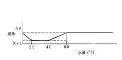
(水温進角補正値設定)
水温補正進角値は、図17に示すマップにより設定するもので、エンジン水温が20゜C〜40゜Cの時は、リタード側に設定し、エンジン水温が20゜Cを下まわると、徐々にアドバンスさせ、また、40゜Cを上まわると、60゜Cまでの間、徐々にアドバンスさせる。
【0069】
(ISC流量制御)
図18は、ISC流量制御のフローチャートで、スタートすると、ステップS1001で、エンジン水温と点火進角のマップによって、ベース流量Cebを設定する。この場合の、ベース流量Cebは、エンジン水温が高い程小さくなり、進角がアドバンス側程小さくなるものである。
【0070】
次に、ステップS1002で、エンジン水温のマップによって、目標回転数No(i)を設定する。この場合、目標回転数No(i)は、エンジン水温が低い程高い値に設定されるものである。
【0071】
そして、ステップS1003で、今回のエンジン回転数Ne(i)の目標回転数No(i)に対する偏差ΔNe(i)を算出し、次いで、ステップS1004で、上記偏差ΔNe(i)に積分定数K1を掛けて、前回のフィードバック補正値Cefb(i−1)に足し込むことより、今回のフィードバック補正値Cefb(i)を算出する。
【0072】
そして、ステップS1005で、今回のベース流量Ceb(i)にフィードバック補正値Cefb(i)を足して、トータルの流量Cetotalを算出し、ステップS1006で、デューティー変換して、出力する。
【0073】
図19は、実施の形態の他の例に示すラフネス制御のための点火時期演算のフローの一部(先の実施の形態のラフネス制御における点火時期演算のフローのステップS114〜127に相当する部分)を示している。先の実施の形態のラフネス制御における点火時期演算では、OBD失火検出値dac(i)が、ラフネス判定の上限しきい値より所定量(例えば3倍)を越える大きい値となった後のラフネス制御によるリタード禁止の時間管理を、タイマ(リタード禁止タイマ)の設定によって行っているが、図19のフローでは、OBD失火検出値dac(i)が、ラフネス判定の上限しきい値より所定量(例えば3倍)を越える大きい値となって、ラフネス制御を禁止した後、高負荷運転に移行し、その高負荷運転の状態が所定期間継続した時に、ラフネス禁止を解除するようになっている。
【0074】
すなわち、図19のステップS1101は、上記図3のステップS115に相当する処理であって、リタード禁止F(フラグ)が1であるかどうかを見る。そして、リタード禁止Fが1でない時は、ステップS1102で、dac(i)がラフネス判定上限しきい値の例えば3倍を越えているかどうかを見て、越えていれば、ステップS1103で、リタード禁止Fを1にし、ステップS1110へ進む。また、dac(i)がラフネス判定上限しきい値の例えば3倍を越えないときは、そのままステップS1110へ進む。
【0075】
次に、ステップS1101で、リタード禁止Fが1であれば、ステップS1104で、高負荷運転状態(高負荷使用中)かどうかを見て、高負荷使用中であれば、ステップS1105で、高負荷タイマを1だけアップカウントする。そして、ステップS1106で、高負荷タイマが所定時間を越えたかどうかを見て、所定時間を越えたら、ラフネス禁止を解除するということで、ステップS1107で、リタード禁止Fを0にリセットし、ステップS1108で、高負荷タイマを0にリセットする。そして、ステップS1110へ進む。また、ステップS1104で、高負荷使用中でない時は、ステップS1109で、高負荷タイマを0にし、ステップS1110に進む。
【0076】
そして、ステップS1110に進むと、点火時期の補正によるラフネス制御の実行条件が成立しているかどうかを、ラフネス補正値リセットF,S/V閉F,アイドルF,車速0F,ギアインF,始動直後禁止タイマ,Br.負圧確保Fおよびラフネス禁止(OBD)Fによって判定する。すなわち、ラフネス補正値リセットF=0,S/V閉F=1,アイドルF=1,車速0F=1,ギアインF=0,始動直後禁止タイマ=0,Br.負圧確保F=0およびラフネス禁止(OBD)F=0の条件が全て成立した時は、ラフネス制御を実行するということで、ステップS1111で、ラフネス実行Fを1とした後、ステップS1112で、ラフネス大判定Fが1かどうかを見て、1であれば、図5のステップステップS128へ進む。また、ラフネス大判定Fが1でなければ、ステップS1113で、ラフネス小判定Fが1で、かつ、リタード禁止Fが0であるかどうかを見て、ラフネス小判定Fが1で、かつ、リタード禁止Fが0でない時は、図5のステップS134へ進む。また、ラフネス小判定Fが1でない時、あるいは、リタード禁止Fが0でない時は、図5のステップS137へ進む。また、ステップS1110で、ラフネス補正値リセットF=0,S/V閉F=1,アイドルF=1,車速0F=1,ギアインF=0,始動直後禁止タイマ=0,Br.負圧確保F=0およびラフネス禁止(OBD)F=0の条件のいずれかが成立しない時は、ラフネス制御を実行しないということで、ステップS1114で、ラフネス実行Fを0とした後、図6のステップS138へ進む。
【0077】
【発明の効果】
本発明によれば、ハイテンションコード抜けや点火コイルの断線等により特定気筒が連続的に失火している状態でラフネス制御を行うことによるエンストや触媒の過熱を防止することができる。
【図面の簡単な説明】
【図1】本発明の実施の形態の一例に係るエンジンの全体システム図である。
【図2】上記実施の形態のラフネス制御における点火時期演算のフローチャートの一部(その1)である。
【図3】上記実施の形態のラフネス制御における点火時期演算のフローチャートの一部(その2)である。
【図4】上記実施の形態のラフネス制御における点火時期演算のフローチャートの一部(その3)である。
【図5】上記実施の形態のラフネス制御における点火時期演算のフローチャートの一部(その4)である。
【図6】上記実施の形態のラフネス制御における点火時期演算のフローチャートの一部(その5)である。
【図7】上記実施の形態のラフネス制御における点火時期演算のフローチャートの一部(その6)である。
【図8】上記実施の形態に係るOBD失火検出値演算のフローチャートである。
【図9】上記実施の形態のラフネス制御に係るラフネス補正値リセットフラグ設定のフローチャートである。
【図10】上記実施の形態のラフネス制御に係るシャッタバルブ開閉判定のフローチャートである。
【図11】上記実施の形態のラフネス制御に係る始動直後禁止タイマ設定のフローチャートである。
【図12】上記実施の形態のラフネス制御に係るマスターバッグ負圧リカバリー制御のタイムチャートである。
【図13】上記実施の形態のラフネス制御に係るブレーキ負圧確保フラグ設定のフローチャートである。
【図14】上記実施の形態のラフネス制御に係るブレーキ負圧確保制御実行タイマ設定のフローチャートである。
【図15】上記実施の形態のラフネス制御に係るブレーキ負圧確保制御実行タイマ設定フラグ設定のフローチャートである。
【図16】上記実施の形態のラフネス制御に係る空燃比フィードバック制御の制御ゲイン変更のフローチャートである。
【図17】上記実施の形態のラフネス制御に係る水温進角補正値設定のマップである。
【図18】上記実施の形態のラフネス制御に係るISC流量制御のフローチャートである。
【図19】本発明の実施の形態のラフネス制御の他の例を示す点火時期演算のフローチャートの一部である。
【符号の説明】
1 エンジン
7 点火プラグ
8 点火回路
13 エアフローセンサ
16 インジェクタ
18 開閉弁(シャッタバルブ)
20 ISCバイパス通路
21 ISCバルブ
22 アイドルスイッチ
26 O2センサ
27 触媒コンバータ
30 クランク角センサ
35 ECU[0001]
BACKGROUND OF THE INVENTION
The present invention includes a catalyst for purifying exhaust gas in the exhaust passage, and, for example, significantly retards the ignition timing at the time of cold start, and promotes activation of the catalyst by increasing the exhaust temperature due to afterburning. The present invention relates to an engine control device that suppresses combustion fluctuations by control.
[0002]
[Prior art]
In general, an automobile engine includes an exhaust gas purifying catalyst in an exhaust passage. And when the catalyst temperature is low, such as at the time of cold start, the catalyst has low catalytic activity and cannot fully exhibit the exhaust gas purification performance. Therefore, in an engine equipped with an exhaust gas purifying catalyst in the exhaust passage, when the engine is cold started, that is, when the engine is started from a cold state, the ignition timing is greatly retarded, and the exhaust temperature is rapidly increased by afterburning. It is necessary to promote the activation of the catalyst. However, if the ignition timing is greatly retarded in order to promote catalyst activation during cold start, the combustion characteristics of the engine will be reduced, and depending on the properties of gasoline as the fuel, especially when there are many heavy components The combustion state becomes extremely unstable. Therefore, conventionally, as described in, for example, Japanese Patent Application Laid-Open No. 8-218995, in a predetermined low output region such as idling, when the catalyst temperature is low, the ignition timing is retarded to reduce the combustibility. At the same time, when the engine torque fluctuation exceeds a predetermined range, a control (roughness control) is performed in which the correction amount of the retardation correction is corrected to be small and the engine combustion fluctuation (roughness) is suppressed. Are known.
[0003]
[Problems to be solved by the invention]
As described above, combustion reduction control such as significantly retarding the ignition timing to promote catalyst activation during cold start is performed, and combustion fluctuations of the engine are suppressed in a predetermined low output region such as during idling. When performing roughness control by correcting the ignition timing, etc., the ignition timing etc. is controlled by the roughness control when the specific cylinder is continuously misfired due to failure of the ignition system such as disconnection of the high tension cord or disconnection of the ignition coil. If corrected to the flammability reduction side, in the situation where a large amount of raw gas was originally discharged due to misfire, the flammability will be reduced to other non-misfire cylinders. There is a possibility that the exhaust temperature rises excessively and the catalyst becomes overheated.
[0004]
Therefore, the problem is to prevent engine stall and catalyst overheating by performing roughness control in a state where a specific cylinder is misfiring continuously due to disconnection of a high tension cord or disconnection of an ignition coil. This is the object of the present invention.
[0005]
[Means for Solving the Problems]
In the present invention, a specific cylinder is continuously misfired due to disconnection of a high tension cord, disconnection of an ignition coil, etc., and roughness control is executed in a situation where a large amount of raw gas is originally discharged, and the ignition timing and the like are reduced in combustibility. If it is corrected to the side, it is due to the fact that the engine stalls as described above or that the catalyst may be in an overheated state, and prevents the engine stall and overheating of the catalyst in such a situation. The engine control device is configured as follows in order to achieve this.
[0006]
That is, the invention according to
[0007]
According to a second aspect of the invention, in the engine control apparatus according to the first aspect of the invention, the specific cylinder abnormality detecting means detects continuous misfire of one cylinder. In this case, if the engine is detected due to continuous misfire of one cylinder, the roughness control is stopped, thereby preventing overheating of the engine stall and the catalyst.
[0008]
According to a third aspect of the present invention, in the engine control device according to the first or second aspect, the specific cylinder abnormality detecting means is configured to continuously misfire a plurality of cylinders whose ignition plugs are energized and controlled by a common ignition coil. Is detected. In this case, when misfire (opposite misfire) of a plurality of cylinders sharing the ignition coil is detected, the roughness control is stopped, thereby preventing the engine stall and the catalyst from overheating.
[0009]
According to a fourth aspect of the present invention, in the engine control apparatus according to the first, second, or third aspect, the combustion fluctuation suppression correcting means is at least one of an ignition timing control means and an air-fuel ratio control means. There is. The correction for suppressing the combustion fluctuation can be performed by either the ignition timing control or the air-fuel ratio control in this way, and can also be performed by using both the ignition timing control means and the air-fuel ratio control means.
[0010]
The invention according to
[0011]
DETAILED DESCRIPTION OF THE INVENTION
Hereinafter, embodiments of the present invention will be described with reference to the drawings.
[0012]
1 to 18 relate to an example of the embodiment, FIG. 1 is an overall system diagram of the engine, FIGS. 2 to 7 are flowcharts of roughness control (ignition timing calculation), and FIG. 8 is an OBD misfire detection value calculation. FIG. 9 is a flowchart of setting a roughness correction value reset flag related to roughness control, FIG. 10 is a flowchart of shutter valve opening / closing determination related to roughness control, FIG. 11 is a flowchart of setting a prohibition timer immediately after start related to roughness control, and FIG. Is a time chart of master bag negative pressure recovery control relating to roughness control, FIG. 13 is a flowchart of setting a brake negative pressure ensuring flag relating to roughness control, FIG. 14 is a flowchart of setting a brake negative pressure ensuring control execution timer relating to roughness control, and FIG. 15 is a brake negative pressure securing control execution timer related to roughness control. FIG. 16 is a flowchart for changing the control gain of air-fuel ratio feedback control related to roughness control, FIG. 17 is a map for setting a water temperature correction advance value related to roughness control, and FIG. 18 is an ISC flow control related to roughness control. It is a flowchart of.
[0013]
An
[0014]
In addition, in order to supply air (intake air) to the
[0015]
In the common intake passage 9, a hot wire type air flow sensor that detects an air flow rate (amount of intake air actually sucked into the engine 1) in order from the upstream side (the right end side in FIG. 1) in the air flow direction. 13 and a
[0016]
Each
[0017]
The upstream side and the downstream side of the common intake passage 9 are connected to each other by an ISC (Idle Speed Control)
[0018]
Further, the
[0019]
The
[0020]
The
[0021]
The outline of the control performed by the
[0022]
That is, in the tumble control, the shutter valve 18 for each
[0023]
In the fuel injection control, basically, the air-fuel ratio of the air-fuel mixture supplied to each
[0024]
In the ISC control, basically, a base flow rate is set based on the engine water temperature detected by the
[0025]
In the control of the ignition timing, basically, for each cylinder, using the map of the engine speed and the intake charging efficiency, MBT, that is, the ignition timing at which the
[0026]
At the time of starting from the cold state, that is, at the time of cold starting, the ignition timing is greatly increased so as to promote the activation of the catalyst of the
[0027]
Thus, based on the signal from the
[0028]
Hereinafter, based on the flowcharts shown in FIGS. 2 to 11, 13 to 16, and 18, and with reference to FIGS. 12 and 17, a specific control method of the roughness control will be described.
[0029]
(Ignition timing calculation)
The roughness control is based on ignition timing control. The processing flow is as shown in FIGS. 2 to 7. When the process starts, first, in step S101, the misfire detection value dac (i for intermittent / continuous misfire of OBD is performed. ) And the misfire detection value dac7c (i) for counter misfire. These OBD misfire detection values dac (i) and dac7c (i) are calculated by a known flow shown in FIG. 8, as will be described later.
[0030]
If it is determined that the OBD is continuous / intermittent or opposite complete misfire, the roughness control is prohibited. Therefore, in step S102, intermittent / continuous from a map of Ce (intake charging efficiency) and Ne (engine speed). The threshold value for the misfiring OBD misfire determination is searched. Similarly, in step S103, the OBD misfire determination threshold value for the counter misfire is searched from the Ce and Ne maps.
[0031]
Next, in step S104, the threshold value for roughness determination is searched first from the Ce and Ne map for the advance side threshold value (upper limit threshold value) corresponding to the stable combustion limit. In step S105, 0 (zero) is set as the retard threshold (lower threshold).
[0032]
Next, misfire determination and roughness determination are performed. For example, for about 1 second immediately after start-up, a large angular velocity is generated even during normal combustion while the engine is starting up. During that time, OBD misfire determination is performed. I can't. Therefore, in step S106, it is determined whether or not a predetermined time (for example, 1 second) has elapsed after the start depending on whether or not the time timer after the start is 0 (zero). If the predetermined time has passed, the process proceeds to step S107, whether the misfire detection value dac (i) for intermittent / continuous misfire exceeds the threshold value, or the misfire detection value dac7c (i for counter misfire). ) Exceeds the threshold. If either dac (i) or dac7c (i) exceeds the threshold value, it is determined that the OBD is completely misfired, and at this time, roughness control is prohibited due to OBD misfire. In step S108, the roughness prohibition (OBD) F (flag) is set to 1, and the process proceeds to the next step S109. If dac (i) or dac7c (i) does not exceed the threshold value, it is not an OBD misfire, and the process directly proceeds to step S109. On the other hand, if it is determined in step S106 that the predetermined time has not elapsed after starting, the process proceeds to the next step S109 without doing anything.
[0033]
In steps S109 to S113, the misfire detection value dac (i) for intermittent / continuous misfire is compared with a threshold value to determine roughness.
[0034]
That is, in step S109, it is checked whether dac (i) is equal to or higher than the upper threshold value searched in step S104. If it is equal to or higher than the upper threshold value, the roughness large determination F (flag) is set to 1 in step S110. The roughness small determination F (flag) is set to 0, and the process proceeds to step S114. If dac (i) is smaller than the upper threshold value, it is checked in step S111 whether dac (i) is lower than the lower threshold value (0). Thus, the roughness large determination F (flag) is set to 0 and the roughness small determination F (flag) is set to 1, and the process proceeds to step S114. When dac (i) is not less than or equal to the lower threshold value (0), that is, when it is smaller than the upper threshold value and larger than the lower threshold value, in step S113, the roughness large determination F (flag) and the roughness smallness are small. Both judgments F (flags) are 0 When Then, the process proceeds to step S114.
[0035]
In steps S114 to S119, the dac (i) is returned to the retard side by roughness control depending on whether or not dac (i) is larger than the upper limit threshold value for roughness determination by a predetermined amount (for example, three times). A flag (retard prohibition continuation F) for continuing prohibition of correction is set. In other words, if the ignition timing is corrected to the retard side by roughness control when the combustion state has deteriorated due to smoldering of the ignition plug when left idle, such an ignition will occur because complete misfire will occur and emissions will deteriorate. Abnormalities due to plug smoldering, etc., for example, about three times the roughness judgment upper limit threshold (between the OBD misfire threshold (intermittent / continuous misfire) and the roughness judgment threshold (upper threshold)) If a large combustion fluctuation (dac (i)) exceeding (corresponding) occurs, the ignition timing retard is prohibited for a predetermined time in the subsequent step, and if an abnormality is detected again within the predetermined time, The retard is also prohibited for a predetermined time.
[0036]
That is, in step S114, it is checked whether or not the retard prohibition timer (time-counted down-counter) is 0 (zero). If the retard prohibition timer is 0, dac (i) is judged as roughness in step S115. It is determined whether or not the upper limit threshold is exceeded, for example, three times. If so, the retard prohibit timer is set to a predetermined time (for example, 5 seconds) in step S116, and the process proceeds to step S123. If dac (i) does not exceed, for example, three times the roughness determination upper limit threshold value, it is checked in step S117 whether the retard prohibition continuation F is 1. If retard retard continuation F is 1, In step S118, the retard prohibition timer is set to a predetermined time (for example, 5 seconds). In step S119, the retard prohibition continuation F is set to 0, and the process proceeds to step S123. If the retard prohibition continuation F is not 1 in step S117, the retard prohibition timer is set to 0 in step S120 because the retard prohibition is no longer continued.
[0037]
If the retard prohibition timer is not 0 (timer is running) in step S114, it is checked in step S121 whether dac (i) exceeds, for example, three times the upper threshold value. For example, the retard prohibition continuation F is set to 1 in step S122. Then, the process proceeds to step S123. If dac (i) does not exceed, for example, three times the upper threshold value, nothing is done and the process proceeds to step S123.
[0038]
In step S123, whether or not the condition for executing the roughness control by correcting the ignition timing is satisfied is determined as follows: roughness correction value reset F (flag), S / V (shutter valve) closed F (flag), idle F (flag), Vehicle speed 0 (zero) F (flag), gear-in F (flag), prohibition timer immediately after start, Br. (Brake) Negative pressure securing F (flag) and roughness prohibition (OBD) F are used for determination.
[0039]
The roughness correction value reset F is set based on the engine water temperature according to the flow shown in FIG. 9, as will be described later. The temperature condition for executing the roughness control is that the engine water temperature is 20 ° C to 60 ° C. At this time, the roughness correction value reset F is 0, and when the engine water temperature exceeds 60 ° C, or 20 ° C. When falling below C, the roughness correction value reset F is 1. At this time, roughness control is not performed.
[0040]
Further, the S / V closing F is set by the flow shown in FIG. 10, as will be described later. The roughness control is performed when the engine water temperature during idling is equal to or higher than a predetermined value (60 ° C). At this time, the S / V closing F is 1, and the engine water temperature falls below the predetermined value (60 ° C). At that time, S / Closed F is zero.
[0041]
Roughness control is executed when idling (idle F = 1), when the vehicle speed is 0 (vehicle speed 0F = 1), and when gear is off (gear-in F = 0).
[0042]
Further, as described later, the prohibition timer immediately after starting is set by the flow shown in FIG. 11, and is set to a predetermined value (for example, 1 second) immediately after starting when the engine speed is lower than a predetermined value (for example, 500 rpm). If the rotation speed is 500 rpm or more, the counter counts down, and the condition for executing the roughness control is that the timer value is zero.
[0043]
Also, Br. The negative pressure securing F is set by the flow shown in FIG. 12, as will be described later. The negative pressure securing F is set to 1 when the negative pressure of the brake master bag (vacuum booster) is reduced and the negative pressure needs to be secured. The condition for executing the roughness control is that the negative pressure securing F is zero.
[0044]
The roughness prohibition (OBD) F is set to 1 in the above-described step S108, and the condition for roughness control is that it is 0.
[0045]
Then, the roughness correction value reset F = 0, S / V closed F = 1, idle F = 1, vehicle speed 0F = 1, gear-in F = 0, immediately after start prohibition timer = 0, Br. When all of the conditions of negative pressure securing F = 0 and roughness prohibition (OBD) F = 0 are satisfied, the roughness control is executed. After setting the roughness execution F (flag) to 1 in step S124, the step In S125, whether the large roughness determination F is 1 or not is 1. If it is 1, ignition advance processing as roughness control is performed in steps S128 to 133 as described later. That is, the ignition timing fluctuation suppression correction amount (roughness IG correction value) is set to the advance side. If the large roughness determination F is not 1, it is checked in step S126 if the small roughness determination F is 1 and the retard prohibition timer is 0, and the roughness small determination F is 1 and the retard is detected. When the prohibit timer (set in steps S114 to 122) is 0, in steps S134 to 136, ignition retard processing is performed as roughness control, and the roughness IG correction value is set to the retard side. Further, when the roughness small determination F is not 1, or when the retard prohibition timer is not 0, the process proceeds to step S137 described later. In step S123, the roughness correction value reset F = 0, S / V closed F = 1, idle F = 1, vehicle speed 0F = 1, gear-in F = 0, immediately after start prohibition timer = 0, Br. When either of the conditions of securing negative pressure F = 0 and roughness prohibition (OBD) F = 0 is not satisfied, the roughness control is not executed. In step S127, after the roughness execution F is set to 0, Steps S138 to 147 are performed.
[0046]
When the roughness large determination F is 1 and the processing of steps S128 to 133 is started, first, in step S128, the deviation of the OBD misfire detection value dac (i) with respect to the upper limit threshold value of the roughness determination is multiplied by a proportionality constant Kp. A basic advance amount ΔIGAD is calculated. Then, as basic advance amount limiter processing, in step S129, it is checked whether or not ΔIGAD exceeds a predetermined value (for example, 1 ° of crank angle), and if it exceeds, ΔIGAD is set to a predetermined value (for example, crank angle of 1) in step S130. )), The process proceeds to step S131. If not, the process proceeds to step S131. In step S131, ΔIGAD is added to the previous roughness IG correction value (i−1) to set a new roughness correction value (i). In step S132, the new roughness IG correction value (i) is obtained. Whether or not it exceeds a certain amount (for example, a crank angle of 20 °), if so, in step S133, the roughness IG correction value (i) is clipped to a predetermined value (for example, a crank angle of 20 °) to be described later. The process proceeds to S148 to 152, and if not exceeded, the process proceeds to steps S148 to 152 as it is.
[0047]
Further, when the roughness small determination F is 1 and the retard prohibition timer is 0 and the processing of steps S134 to 136 is started, in step S134, a predetermined value (for example, crank angle) is determined from the previous roughness IG correction value (i-1). To 0.1 °) to set a new roughness IG correction value (i). In step S135, the new roughness IG correction value (i) falls below a predetermined value (for example, −20 ° of the crank angle). When the rotation is reduced, the roughness IG correction value (i) is clipped to a predetermined value (for example, −20 ° of crank angle) in step S136, and the process proceeds to steps S148 to 152 again. If not, the process proceeds to steps S148 to 152 as it is.
[0048]
When the small roughness determination F is not 1 in step S126 or when the retard prohibition timer is not 0, the roughness IG correction value (i) is fixed to the previous roughness IG correction value (i-1) in step S137. .
[0049]
If the execution conditions of the roughness control are not satisfied and the processing of steps S138 to 147 is started, first, in step S138, the roughness correction value reset F (set based on the engine water temperature by the flow shown in FIG. 9) is performed. Whether the roughness correction value reset F is 0 or whether the roughness prohibition (OBD) F is 0 is determined by checking whether the roughness prohibition (OBD) F (set in step S108) is 0 or not. If it is 0, the roughness IG correction value (i) is fixed to the previous roughness IG correction value (i−1) in step S139, and the process proceeds to steps S148 to 152.
[0050]
If the determination in step S138 is NO and the roughness correction value reset F and the roughness prohibition (OBD) F are not 0, in step S140, the previous roughness IG correction value (i-1) is a positive value (> 0), if it is a positive value, in step S141, a predetermined value (for example, 0.01 ° of the crank angle) is subtracted from the previous roughness IG correction value (i-1) to obtain a new value. The roughness IG correction value (i) is set, and whether or not the new roughness IG correction value (i) falls below 0 is determined in step S142. When the roughness IG correction value (i) falls below 0, the roughness IG correction value is determined in step S143. (I) is clipped to 0, and the process proceeds to steps S148 to 152 again. If it is not a negative value, the process proceeds to steps S148 to 152 as it is.
[0051]
If the previous roughness IG correction value (i−1) is not a positive value (> 0) in step S140, the previous roughness IG correction value (i−1) is a negative value (<0) in step S144. If it is a negative value, in step S145, a predetermined value (for example, 0.01 ° of crank angle) is added to the previous roughness IG correction value (i-1) to obtain a new roughness IG correction value. (I) is set, and whether or not the new roughness IG correction value (i) exceeds 0 in step S146, and if it exceeds 0, the roughness IG correction value (i) is set in step S147. Clip to 0 and proceed to steps S148 to 152 as well. If the value is not a negative value, proceed to steps S148 to 152 as it is.
[0052]
If the previous roughness IG correction value (i-1) is neither a positive value nor a negative value, that is, 0, the process proceeds to steps S148 to 152 as it is.
[0053]
In steps S148 to 152, the basic ignition timing during idling is set according to the map. The basic ignition timing is when the roughness control is performed or not performed when the shutter valve (S / V) 18 is open and when the shutter valve 18 is closed, and when the shutter valve 18 is closed. And the settings are different. First, in step S148, whether or not S / V closed F is 1 (S / V closed F is set by the flow shown in FIG. 10), and if S / V closed F is 1, In step S149, whether or not the roughness correction value reset F (set by the flow shown in FIG. 9) due to the engine water temperature is 1, and if the roughness correction value reset F is 1, then in step S150, the intake charge efficiency ( The basic ignition timing (idle basic advance angle (i)) at idling is set by searching the basic IG map for idling, S / V closing, and roughness non-operation set by Ce) and engine speed (Ne). Then, the process proceeds to step S153 for setting the final ignition timing. Further, when the roughness correction value reset F is not 1, that is, while the roughness control is being executed, in step S151, the idling value S / S / having a constant setting regardless of changes in the engine speed (Ne) and the intake charging efficiency (Ce). Using the basic IG map for V closing / roughness operation, the basic idle angle (i) is set to a constant value, and the process proceeds to step S153. If the S / V closing F is not 1 in step S148, the idle basic advance angle (i) is set by the basic IG map for idling / S / V opening in step S152, and the process proceeds to step S153. .
[0054]
In step S153, the idle basic advance angle (i), roughness IG correction value (i), Br. Add the negative pressure ensuring correction value (i), the water temperature advance angle correction value (i), and various other advance angle correction values (e.t.c.) during normal idling to obtain the final ignition timing. Set the idle advance angle (i) that is and return. The water temperature advance angle correction value (i) is set by a map shown in FIG. 17, as will be described later.
[0055]
(OBD misfire detection value calculation)
FIG. 8 is a flowchart of the known OBD misfire detection value calculation. When started, in S201, the crank angle pulse time of ATDC 80 ° to ATDC 260 ° corresponding to the crank angle range of 180 ° from the latter half of the expansion stroke to the first half of the exhaust stroke is shown. The measured value T (i) is input. In step S202, the angular velocity av (i) is calculated by multiplying the value obtained by dividing 180 ° (360 ° / 2) by T (i) by the tolerance correction coefficient mscf, and then in step S203, this time The angular acceleration ca (i) is calculated by dividing the difference between the previous angular velocity av (i) and the previous angular velocity av (i−1) by T (i).
[0056]
In the next step S204, the angular acceleration (measured values) ca (i) to ca (i-4) of the five points before and after the ignition order including the current time, and the median value camd5 (i) of the five points in the ignition order including the current time. The median value camd7 (i) of the angular accelerations (measured values) ca (i) to ca (i-6) of the points is calculated. Then, in step S205, the angular accelerations ca (i) to ca (i) of the five points are calculated. -4) Calculate the deviation dac (i) of the angular acceleration ca (i-2) at the middle measurement point in the middle with respect to the median value camd5 (i). Is the OBD misfire detection value for the continuous / intermittent fire for the middle cylinder, and the angular acceleration ca (i−) at the middle measurement point of the seven angular accelerations ca (i) to ca (i-6). 3) calculating the deviation dac7 (i) with respect to the median value camd7 (i) Is calculated as the OBD misfire detection value for counter misfire for the cylinder in which the ignition order is the middle of the seven times before and after this time. Here, the continuous misfire refers to the case where a specific cylinder continuously misfires, and the intermittent fire refers to the case where an unspecified cylinder intermittently misfires. The counter misfire refers to misfire of a plurality of cylinders in which the ignition coil is energized and controlled by a common ignition coil.
[0057]
Then, the process is returned and the above process is repeated, and the OBD misfire detection value dac (i) for continuous / intermittent fire and the OBD misfire detection value dac7 (i) for counterfire are calculated for every cylinder.
[0058]
(Roughness correction value reset flag setting)
FIG. 9 is a flowchart for setting a roughness correction value reset flag. When started, it is checked in S301 whether the engine water temperature is higher than 60 ° C. or lower than 20 ° C. If the engine water temperature is higher than 60 ° C. or lower than 20 ° C., the roughness correction value reset F (flag) is set to 1 in step S302. If the engine water temperature is neither higher than 60 ° C. nor lower than 20 ° C., the roughness correction value reset F is set to 0 in step S303.
[0059]
(Shutter valve open / close judgment)
FIG. 10 is a flowchart for determining whether the shutter valve is open or closed. When started, it is checked in step S401 whether the idle F (flag) is “1”. When the idling F is 1 (during idling), it is determined in
[0060]
When the idle F is not 1 (off-idle), in step S405, the shutter valve (S / V) closed region is set based on the intake charging efficiency (Ce), the engine speed (Ne), and the engine water temperature. Search for Ce (S / V closed Ce) as a threshold value of the S / V closed region (which becomes narrower as the engine water temperature becomes higher) according to the engine water temperature from the map (S / V closed Ce map). In S406, it is checked whether the measured Ce is smaller than S / V closed Ce. If Ce is smaller than S / V closed Ce, the S / V closed flag is set to 1 in step S407, and Ce is If it is equal to or greater than S / V closing Ce, the S / V closing flag is set to 0 in step S408.
[0061]
(Prohibit timer setting immediately after starting)
FIG. 11 is a flowchart of setting a prohibit timer immediately after starting. When starting, in S501, immediately after starting the engine, it is checked whether the engine speed (Ne) is lower than 500 rpm, for example, and when Ne is lower than 500 rpm, for example. Immediately after the prohibit timer is set to a predetermined value (for example, 1 second), if Ne becomes 500 rpm or more, the prohibit timer immediately after starting is counted down and clipped at 0.
[0062]
(Master bag negative pressure recovery control)
FIG. 12 is a time chart of the master bag negative pressure recovery control. The execution timer (Br. Negative pressure ensuring control execution timer) is set to an initial set value (for example, 20 seconds) for a predetermined time (for example, 1 to 20 seconds) after the engine is started. ) And is counted down after the predetermined time has elapsed. Meanwhile, Br. When the negative pressure ensuring correction value is 0 and the execution timer becomes 0, the execution timer is clipped to 0, and Br. The negative pressure securing correction value is gradually increased. And Br. When the negative pressure securing correction value becomes a value that cancels the roughness IG correction value, the execution timer setting F (flag) is set to 1, the execution timer is set again to the setting value (for example, 20 seconds), and Br. The negative pressure securing correction value is gradually reduced to zero. Br. For stopping roughness control. The negative pressure securing F (flag) is set to 1 when the execution timer reaches 0, and Br. While the negative pressure securing correction value exceeds 0, the value of Br. When the negative pressure securing correction value becomes zero, it returns to zero.
[0063]
FIG. 13 is a flowchart for setting a brake negative pressure securing flag. When started, in step S601, Br. Check whether the negative pressure securing control execution timer is 0 or not. And Br. If the negative pressure ensuring control execution timer is 0, in step S602, the previous Br. Add a predetermined amount (for example, 0.3 ° of the crank angle) to the negative pressure ensuring correction value (i−1) to obtain a new Br. The negative pressure securing correction value (i) is set, and in step S603, Br. Seeing whether the negative pressure securing correction value (i) exceeds 0, Br. If the negative pressure securing correction value (i) exceeds 0, in step S604, Br. Negative pressure securing F (flag) is set to 1, Br. If the negative pressure securing correction value (i) does not exceed 0, in step S605, Br. The negative pressure securing F (flag) is set to zero.
[0064]
In step S601, Br. When the negative pressure ensuring control execution timer is not 0, in step S606, the previous Br. By subtracting a predetermined amount (for example, 0.3 ° of crank angle) from the negative pressure ensuring correction value (i−1), a new Br. The negative pressure securing correction value (i) is set, and in step S607, Br. Seeing whether the negative pressure securing correction value (i) has fallen below 0, Br. When the negative pressure securing correction value (i) falls below 0, in step S608, Br. Clip the negative pressure securing correction value (i) to 0. In step S603, Br. Seeing whether the negative pressure securing correction value (i) exceeds 0, Br. If the negative pressure ensuring correction value (i) exceeds 0, in step S604, Br. Negative pressure securing F (flag) is set to 1, Br. If the negative pressure securing correction value (i) does not exceed 0, in step S605, Br. The negative pressure securing F (flag) is set to zero.
[0065]
FIG. 14 is a flowchart for setting a brake negative pressure ensuring control execution timer. Check whether the negative pressure ensuring correction value (i) is equal to or greater than the value obtained by multiplying the roughness IG correction value (i) by a constant Kc (for example, -0.8) (a value that substantially cancels the roughness IG correction value). If the secured correction value (i) is not less than the value obtained by multiplying the roughness IG correction value (i) by a constant Kc (for example, -0.8), in step S702, Br. The negative pressure securing control execution timer setting F (flag) is set to 1. If the negative pressure ensuring correction value (i) is not equal to or greater than the value obtained by multiplying the roughness IG correction value (i) by a constant Kc (for example, -0.8), in step S703, Br. It is checked whether the negative pressure ensuring control execution timer (i) is a value exceeding 0, and if it exceeds 0, in step S704, Br. The negative pressure securing control execution timer setting F is set to 0, and if it does not exceed 0, the process returns as it is.
[0066]
FIG. 15 is a flowchart for setting a brake negative pressure ensuring control execution timer setting flag. One of the following conditions is satisfied: negative pressure securing control execution timer setting F is 1, post-start prohibition timer is 0 or more, roughness correction value reset F is 1, idle F is 0, vehicle speed 0F is 1, and gear-in F is 1 If any of the above conditions is satisfied, in step S802, Br. The negative pressure ensuring control execution timer is set to a predetermined value (for example, 20 seconds). When none of the above conditions is satisfied, Br. The negative pressure securing control execution timer is counted down and clipped at 0.
[0067]
(Air-fuel ratio feedback control gain change)
FIG. 16 is a flowchart for changing the control gain of the air-fuel ratio feedback control. When starting, it is checked in step S901 whether the idle F is 1. When the idle F is 1 (during idle), it is checked in step S902 whether the roughness execution F is 1. When the roughness execution F is 1, the proportional term OKP, the integral term OKI and others are in step S903. The control gain of (differential term, etc.) is a control gain dedicated to roughness control, and when the roughness execution F is not 1, in step S904, the control gain is set as a normal control gain during idling. When the idle F is not 1 (non-idle), in step S905, the control gain is set to the control gain during traveling. The control gain dedicated to roughness control, the normal control gain during idling, and the control gain during driving increase in the order of the control gain dedicated for roughness control, the normal control gain during idling, and the control gain during driving. .
[0068]
(Water temperature advance angle correction value setting)
The water temperature correction advance value is set according to the map shown in FIG. 17. When the engine water temperature is 20 ° C. to 40 ° C., it is set to the retard side, and when the engine water temperature falls below 20 ° C., it is gradually increased. Also, when the temperature exceeds 40 ° C, it is gradually advanced to 60 ° C.
[0069]
(ISC flow control)
FIG. 18 is a flowchart of ISC flow rate control. When started, in step S1001, the base flow rate Ceb is set by a map of engine water temperature and ignition advance angle. In this case, the base flow rate Ceb decreases as the engine water temperature increases, and the advance angle decreases as the advance side increases.
[0070]
Next, in step S1002, the target rotational speed No (i) is set according to the engine water temperature map. In this case, the target rotational speed No (i) is set to a higher value as the engine water temperature is lower.
[0071]
In step S1003, a deviation ΔNe (i) of the current engine speed Ne (i) with respect to the target speed No (i) is calculated. In step S1004, an integral constant K1 is set to the deviation ΔNe (i). The current feedback correction value Cefb (i) is calculated by multiplying and adding to the previous feedback correction value Cefb (i-1).
[0072]
In step S1005, the feedback correction value Cefb (i) is added to the current base flow rate Ceb (i) to calculate a total flow rate Cetal. In step S1006, the duty is converted and output.
[0073]
FIG. 19 shows a part of the flow of the ignition timing calculation for the roughness control shown in another example of the embodiment (the part corresponding to steps S114 to 127 of the flow of the ignition timing calculation in the roughness control of the previous embodiment) ). In the ignition timing calculation in the roughness control of the previous embodiment, the roughness control after the OBD misfire detection value dac (i) becomes a value that exceeds a predetermined amount (for example, three times) larger than the upper limit threshold value of the roughness determination. In the flow of FIG. 19, the OBD misfire detection value dac (i) is set to a predetermined amount (for example, the roughness determination upper limit threshold value). After the prohibition of the roughness control, the shift to the high load operation is performed, and the prohibition of the roughness is canceled when the state of the high load operation continues for a predetermined period.
[0074]
That is, step S1101 in FIG. 19 is processing corresponding to step S115 in FIG. 3, and checks whether the retard inhibition F (flag) is 1. If retard prohibition F is not 1, in step S1102, it is checked whether dac (i) exceeds, for example, three times the roughness determination upper limit threshold. If so, retard prohibition is performed in step S1103. Set F to 1 and proceed to Step S1110. On the other hand, when dac (i) does not exceed, for example, three times the roughness determination upper limit threshold value, the process proceeds to step S1110 as it is.
[0075]
Next, if the retard prohibition F is 1 in step S1101, it is determined in step S1104 whether the high load operation state (high load is being used). If the high load is being used, the high load is determined in step S1105. Count up the timer by one. In step S1106, it is determined whether the high load timer has exceeded a predetermined time. If the predetermined time is exceeded, the roughness prohibition is canceled. In step S1107, the retard prohibition F is reset to 0, and step S1108 is performed. The high load timer is reset to zero. Then, the process proceeds to step S1110. If it is determined in step S1104 that the high load is not being used, the high load timer is set to 0 in step S1109, and the process proceeds to step S1110.
[0076]
Then, in step S1110, whether or not the condition for executing the roughness control by correcting the ignition timing is satisfied, the roughness correction value reset F, S / V closed F, idle F, vehicle speed 0F, gear-in F, and prohibition immediately after starting. Timer, Br. Judgment is made by negative pressure securing F and roughness prohibition (OBD) F. That is, roughness correction value reset F = 0, S / V closed F = 1, idle F = 1, vehicle speed 0F = 1, gear-in F = 0, immediately after start prohibition timer = 0, Br. When all of the conditions of negative pressure securing F = 0 and roughness prohibition (OBD) F = 0 are satisfied, the roughness control is executed. In step S1111, the roughness execution F is set to 1, and then in step S1112, When it is determined whether the roughness large determination F is 1, the process proceeds to step S128 in FIG. If the large roughness determination F is not 1, it is determined in step S1113 whether the small roughness determination F is 1 and the retard prohibition F is 0. The small roughness determination F is 1 and the retard When the prohibition F is not 0, the process proceeds to step S134 in FIG. Further, when the roughness small determination F is not 1, or when the retard prohibition F is not 0, the process proceeds to step S137 in FIG. In step S1110, the roughness correction value reset F = 0, S / V closed F = 1, idle F = 1, vehicle speed 0F = 1, gear-in F = 0, immediately after start prohibition timer = 0, Br. When either of the conditions of securing negative pressure F = 0 and roughness prohibition (OBD) F = 0 is not satisfied, the roughness control is not executed, so that the roughness execution F is set to 0 in step S1114, and then FIG. The process proceeds to step S138.
[0077]
【The invention's effect】
According to the present invention, it is possible to prevent engine stall and catalyst overheating by performing roughness control in a state where a specific cylinder is continuously misfired due to disconnection of a high tension cord or disconnection of an ignition coil.
[Brief description of the drawings]
FIG. 1 is an overall system diagram of an engine according to an example of an embodiment of the present invention.
FIG. 2 is a part (part 1) of a flowchart of ignition timing calculation in the roughness control of the embodiment.
FIG. 3 is a part (part 2) of the flowchart of the ignition timing calculation in the roughness control of the embodiment.
FIG. 4 is a part (part 3) of a flowchart of ignition timing calculation in the roughness control of the embodiment.
FIG. 5 is a part (No. 4) of the flowchart of the ignition timing calculation in the roughness control of the embodiment.
FIG. 6 is a part (No. 5) of the flowchart of the ignition timing calculation in the roughness control of the embodiment.
FIG. 7 is a part (No. 6) of the flowchart of the ignition timing calculation in the roughness control of the embodiment.
FIG. 8 is a flowchart of OBD misfire detection value calculation according to the embodiment.
FIG. 9 is a flowchart for setting a roughness correction value reset flag according to the roughness control of the embodiment.
FIG. 10 is a flowchart of shutter valve opening / closing determination relating to roughness control according to the embodiment.
FIG. 11 is a flowchart for setting a prohibit timer immediately after start according to the roughness control of the embodiment.
FIG. 12 is a time chart of master bag negative pressure recovery control according to roughness control of the embodiment.
FIG. 13 is a flowchart for setting a brake negative pressure securing flag according to the roughness control of the embodiment.
FIG. 14 is a flowchart for setting a brake negative pressure ensuring control execution timer according to the roughness control of the embodiment.
FIG. 15 is a flowchart for setting a brake negative pressure ensuring control execution timer setting flag according to the roughness control of the embodiment.
FIG. 16 is a flowchart of control gain change of air-fuel ratio feedback control according to roughness control of the embodiment.
FIG. 17 is a map for setting a water temperature advance angle correction value according to the roughness control of the embodiment.
FIG. 18 is a flowchart of ISC flow control related to roughness control of the embodiment.
FIG. 19 is a part of a flowchart of ignition timing calculation showing another example of roughness control according to the embodiment of the present invention.
[Explanation of symbols]
1 engine
7 Spark plug
8 Ignition circuit
13 Air flow sensor
16 Injector
18 On-off valve (shutter valve)
20 ISC bypass passage
21 ISC valve
22 Idle switch
26 O2 sensor
27 Catalytic converter
30 Crank angle sensor
35 ECU
Claims (5)
上記エンジンの燃焼状態を制御する燃焼制御手段と、
上記エンジンの燃焼変動を検出する燃焼変動検出手段と、
上記触媒が未活性状態にあって、点火時期を遅角させることにより排気温度を上昇させて上記触媒の活性化を促進している時に、上記エンジンの燃焼変動が所定値以下となるよう、上記燃焼制御手段による燃焼制御の制御量に対し変動抑制補正量を設定する燃焼変動抑制補正手段と、
特定気筒の連続失火を検出する特定気筒異常検出手段と、
該特定気筒異常検出手段により特定気筒の連続失火が検出された時、上記燃焼変動抑制補正手段の作動を停止する停止手段とを備えたことを特徴とするエンジンの制御装置。Composed of a plurality of cylinders and equipped with an exhaust gas purification catalyst in the exhaust passage, and when the catalyst is in an inactive state, the ignition timing is retarded to increase the exhaust temperature and promote the activation of the catalyst. An engine control device adapted to
Combustion control means for controlling the combustion state of the engine;
Combustion fluctuation detecting means for detecting the combustion fluctuation of the engine;
When the catalyst is in an inactive state and the exhaust temperature is increased by retarding the ignition timing to promote the activation of the catalyst , the engine combustion fluctuation is reduced to a predetermined value or less. Combustion fluctuation suppression correction means for setting a fluctuation suppression correction amount with respect to a control amount of combustion control by the combustion control means;
Specific cylinder abnormality detection means for detecting continuous misfire of the specific cylinder;
An engine control device comprising: a stopping means for stopping the operation of the combustion fluctuation suppression correcting means when the specific cylinder abnormality detecting means detects a continuous misfire of the specific cylinder.
Priority Applications (1)
| Application Number | Priority Date | Filing Date | Title |
|---|---|---|---|
| JP08545799A JP4306004B2 (en) | 1999-03-29 | 1999-03-29 | Engine control device |
Applications Claiming Priority (1)
| Application Number | Priority Date | Filing Date | Title |
|---|---|---|---|
| JP08545799A JP4306004B2 (en) | 1999-03-29 | 1999-03-29 | Engine control device |
Publications (2)
| Publication Number | Publication Date |
|---|---|
| JP2000283015A JP2000283015A (en) | 2000-10-10 |
| JP4306004B2 true JP4306004B2 (en) | 2009-07-29 |
Family
ID=13859420
Family Applications (1)
| Application Number | Title | Priority Date | Filing Date |
|---|---|---|---|
| JP08545799A Expired - Fee Related JP4306004B2 (en) | 1999-03-29 | 1999-03-29 | Engine control device |
Country Status (1)
| Country | Link |
|---|---|
| JP (1) | JP4306004B2 (en) |
Families Citing this family (6)
| Publication number | Priority date | Publication date | Assignee | Title |
|---|---|---|---|---|
| JP4894935B2 (en) * | 2005-01-11 | 2012-03-14 | トヨタ自動車株式会社 | Misfire determination device and misfire determination method for internal combustion engine |
| JP4946710B2 (en) * | 2007-08-08 | 2012-06-06 | スズキ株式会社 | Engine control device |
| JP4901814B2 (en) * | 2008-06-16 | 2012-03-21 | 本田技研工業株式会社 | Control device for internal combustion engine |
| JP5029565B2 (en) * | 2008-10-09 | 2012-09-19 | トヨタ自動車株式会社 | Engine control device |
| JP5962463B2 (en) * | 2012-11-27 | 2016-08-03 | 三菱自動車工業株式会社 | Engine start determination device |
| JP7096852B2 (en) * | 2020-02-25 | 2022-07-06 | 本田技研工業株式会社 | Engine control unit |
-
1999
- 1999-03-29 JP JP08545799A patent/JP4306004B2/en not_active Expired - Fee Related
Also Published As
| Publication number | Publication date |
|---|---|
| JP2000283015A (en) | 2000-10-10 |
Similar Documents
| Publication | Publication Date | Title |
|---|---|---|
| JP5505447B2 (en) | Control device for internal combustion engine | |
| JP5451687B2 (en) | Engine control device | |
| CN108386261B (en) | Catalyst degradation determination device | |
| JPH0914027A (en) | Control device of internal combustion engine and control device of vehicle | |
| JPS60237142A (en) | Controller for internal-combustion engine | |
| EP0866219B1 (en) | Fuel cut control apparatus for internal combustion engine | |
| JP2018141445A (en) | Control device of vehicle | |
| US6302082B1 (en) | Ignition timing control system for internal combustion engine | |
| JP2003172170A (en) | Brake negative pressure control device for internal combustion engine | |
| JP2000310144A (en) | Control device for internal combustion engine | |
| US6003489A (en) | Fuel injection control device of in-cylinder type internal combustion engine | |
| JP4306004B2 (en) | Engine control device | |
| JP3541523B2 (en) | Engine control device | |
| JP7035749B2 (en) | Internal combustion engine misfire detector | |
| JPS60166734A (en) | Fuel feed controlling method of multicylinder internal- combustion engine | |
| JPS58217746A (en) | Feedback control method of air-fuel ratio for internal-combustion engine | |
| JP4120614B2 (en) | Start control device for internal combustion engine | |
| JPS5934441A (en) | Control method of air-fuel ratio of internal-combustion engine | |
| JPH1026034A (en) | Acceleration slip control device for vehicle | |
| JP3963105B2 (en) | Control device for internal combustion engine | |
| JP3973390B2 (en) | Intake pressure detection method for internal combustion engine | |
| JP2013181486A (en) | Control device for internal combustion engine | |
| JP2013133790A (en) | Control device of internal combustion engine | |
| JP2000291467A (en) | Control device for internal combustion engine | |
| JPS59188041A (en) | Fuel-feed control for deceleration of internal- combustion engine |
Legal Events
| Date | Code | Title | Description |
|---|---|---|---|
| A621 | Written request for application examination |
Free format text: JAPANESE INTERMEDIATE CODE: A621 Effective date: 20060131 |
|
| A977 | Report on retrieval |
Free format text: JAPANESE INTERMEDIATE CODE: A971007 Effective date: 20080728 |
|
| A131 | Notification of reasons for refusal |
Free format text: JAPANESE INTERMEDIATE CODE: A131 Effective date: 20080930 |
|
| A521 | Written amendment |
Free format text: JAPANESE INTERMEDIATE CODE: A523 Effective date: 20081125 |
|
| TRDD | Decision of grant or rejection written | ||
| A01 | Written decision to grant a patent or to grant a registration (utility model) |
Free format text: JAPANESE INTERMEDIATE CODE: A01 Effective date: 20090414 |
|
| A01 | Written decision to grant a patent or to grant a registration (utility model) |
Free format text: JAPANESE INTERMEDIATE CODE: A01 |
|
| A61 | First payment of annual fees (during grant procedure) |
Free format text: JAPANESE INTERMEDIATE CODE: A61 Effective date: 20090427 |
|
| R150 | Certificate of patent or registration of utility model |
Free format text: JAPANESE INTERMEDIATE CODE: R150 |
|
| FPAY | Renewal fee payment (event date is renewal date of database) |
Free format text: PAYMENT UNTIL: 20120515 Year of fee payment: 3 |
|
| FPAY | Renewal fee payment (event date is renewal date of database) |
Free format text: PAYMENT UNTIL: 20130515 Year of fee payment: 4 |
|
| FPAY | Renewal fee payment (event date is renewal date of database) |
Free format text: PAYMENT UNTIL: 20140515 Year of fee payment: 5 |
|
| LAPS | Cancellation because of no payment of annual fees |