JP4303253B2 - Library device and robot hand for library device - Google Patents
Library device and robot hand for library device Download PDFInfo
- Publication number
- JP4303253B2 JP4303253B2 JP2006045005A JP2006045005A JP4303253B2 JP 4303253 B2 JP4303253 B2 JP 4303253B2 JP 2006045005 A JP2006045005 A JP 2006045005A JP 2006045005 A JP2006045005 A JP 2006045005A JP 4303253 B2 JP4303253 B2 JP 4303253B2
- Authority
- JP
- Japan
- Prior art keywords
- gripping
- gripping claws
- support member
- moving body
- robot hand
- Prior art date
- Legal status (The legal status is an assumption and is not a legal conclusion. Google has not performed a legal analysis and makes no representation as to the accuracy of the status listed.)
- Expired - Fee Related
Links
Images


Classifications
-
- G—PHYSICS
- G11—INFORMATION STORAGE
- G11B—INFORMATION STORAGE BASED ON RELATIVE MOVEMENT BETWEEN RECORD CARRIER AND TRANSDUCER
- G11B15/00—Driving, starting or stopping record carriers of filamentary or web form; Driving both such record carriers and heads; Guiding such record carriers or containers therefor; Control thereof; Control of operating function
- G11B15/675—Guiding containers, e.g. loading, ejecting cassettes
- G11B15/68—Automatic cassette changing arrangements; automatic tape changing arrangements
- G11B15/682—Automatic cassette changing arrangements; automatic tape changing arrangements with fixed magazines having fixed cassette storage cells, e.g. in racks
- G11B15/6835—Automatic cassette changing arrangements; automatic tape changing arrangements with fixed magazines having fixed cassette storage cells, e.g. in racks the cassettes being transferred to a fixed recorder or player using a moving carriage
-
- G—PHYSICS
- G11—INFORMATION STORAGE
- G11B—INFORMATION STORAGE BASED ON RELATIVE MOVEMENT BETWEEN RECORD CARRIER AND TRANSDUCER
- G11B15/00—Driving, starting or stopping record carriers of filamentary or web form; Driving both such record carriers and heads; Guiding such record carriers or containers therefor; Control thereof; Control of operating function
- G11B15/60—Guiding record carrier
- G11B15/66—Threading; Loading; Automatic self-loading
- G11B15/67—Threading; Loading; Automatic self-loading by extracting end of record carrier from container or spool
-
- G—PHYSICS
- G11—INFORMATION STORAGE
- G11B—INFORMATION STORAGE BASED ON RELATIVE MOVEMENT BETWEEN RECORD CARRIER AND TRANSDUCER
- G11B15/00—Driving, starting or stopping record carriers of filamentary or web form; Driving both such record carriers and heads; Guiding such record carriers or containers therefor; Control thereof; Control of operating function
- G11B15/675—Guiding containers, e.g. loading, ejecting cassettes
- G11B15/68—Automatic cassette changing arrangements; automatic tape changing arrangements
-
- G—PHYSICS
- G11—INFORMATION STORAGE
- G11B—INFORMATION STORAGE BASED ON RELATIVE MOVEMENT BETWEEN RECORD CARRIER AND TRANSDUCER
- G11B17/00—Guiding record carriers not specifically of filamentary or web form, or of supports therefor
- G11B17/22—Guiding record carriers not specifically of filamentary or web form, or of supports therefor from random access magazine of disc records
- G11B17/225—Guiding record carriers not specifically of filamentary or web form, or of supports therefor from random access magazine of disc records wherein the disks are transferred from a fixed magazine to a fixed playing unit using a moving carriage
Landscapes
- Automatic Tape Cassette Changers (AREA)
- Manipulator (AREA)
Description
本発明は、例えば磁気テープライブラリ装置といったライブラリ装置に関し、特に、ライブラリ装置内で、磁気テープカートリッジといった搬送物を収容するセルに対して位置決めされるロボットハンドに関する。 The present invention relates to a library device such as a magnetic tape library device, and more particularly to a robot hand positioned in a library device with respect to a cell that accommodates a transported object such as a magnetic tape cartridge.
磁気テープライブラリ装置では、所定の待避域に隣接する作動領域内でセルに対してロボットハンドが位置決めされる。ロボットハンドには把持爪が搭載される。把持爪はセル内の磁気テープカートリッジを掴み取る。こうしてロボットハンドの移動に基づき磁気テープカートリッジは磁気テープライブラリ装置内で搬送される。
ロボットハンドが故障すると、ロボットハンドは待避域まで搬送される。このとき、把持爪の移動経路上にセルや磁気テープカートリッジが存在すると、ロボットハンドの搬送は妨げられる。ロボットハンドは待避域まで行き着くことができない。例えば作動領域内でバックアップ用ロボットハンドの移動は妨げられる。冗長性は失われてしまう。 When the robot hand breaks down, the robot hand is transported to the waiting area. At this time, if a cell or a magnetic tape cartridge exists on the movement path of the gripping claw, the conveyance of the robot hand is hindered. The robot hand cannot reach the evacuation zone. For example, the movement of the backup robot hand in the operating area is prevented. Redundancy is lost.
本発明は、上記実状に鑑みてなされたもので、確実に待避域までロボットハンドを移動させることができるライブラリ装置を提供することを目的とする。 The present invention has been made in view of the above circumstances, and an object of the present invention is to provide a library apparatus that can reliably move a robot hand to a retreat area.
上記目的を達成するために、本発明によれば、複数のセルを含む収納棚と、移動体と、所定の待避域に隣接する作動領域内でセルに対して移動体を位置決めする位置決め機構と、移動体に搭載されて、任意の水平面に沿って相互に接近離隔する1対の把持爪と、待避域に向かって移動体を駆動する搬送機構と、搬送機構が待避域に向かって移動体を搬送する際に、把持爪の移動経路上の物体から把持爪を回避させる逃げ機構とを備えることを特徴とするライブラリ装置が提供される。 In order to achieve the above object, according to the present invention, a storage shelf including a plurality of cells, a moving body, and a positioning mechanism for positioning the moving body with respect to the cell in an operation area adjacent to a predetermined evacuation area; A pair of gripping claws that are mounted on the moving body and move toward and away from each other along an arbitrary horizontal plane; a transport mechanism that drives the moving body toward the save area; and the transfer mechanism that moves toward the save area And a relief mechanism for avoiding the gripping claw from an object on the movement path of the gripping claw when transporting the object.
こういったライブラリ装置では、通常、位置決め機構の働きで移動体はセルに対して位置決めされる。セル内の対象物は1対の把持爪で把持される。移動体の移動に基づき対象物は搬送される。しかも、位置決め機構に障害が発生すると、移動体は位置決め機構に代わって搬送機構で待避域まで搬送される。このとき、把持爪の移動経路上に物体が存在しても、逃げ機構の働きで把持爪はその物体を回避することができる。その結果、移動体は移動し続けることができる。移動体は確実に待避域に辿り着くことができる。 In such a library apparatus, the moving body is normally positioned with respect to the cell by the action of the positioning mechanism. The object in the cell is gripped by a pair of gripping claws. The object is conveyed based on the movement of the moving body. In addition, when a failure occurs in the positioning mechanism, the moving body is transported to the waiting area by the transport mechanism instead of the positioning mechanism. At this time, even if an object exists on the movement path of the gripping claw, the gripping claw can avoid the object by the action of the escape mechanism. As a result, the moving body can continue to move. The mobile object can reach the evacuation area with certainty.
搬送機構は、バックアップ用移動体と、前記作動範囲内でセルに対してバックアップ用移動体を位置決めするバックアップ用位置決め機構とを備えてもよい。こういった搬送機構によれば、前述の移動体の休止中にバックアップ用移動体は動作することができる。バックアップ用移動体の働きでセル内の対象物は搬送されることができる。したがって、ライブラリ装置は絶え間なく稼働し続けることができる。 The transport mechanism may include a backup moving body and a backup positioning mechanism that positions the backup moving body with respect to the cell within the operating range. According to such a transport mechanism, the backup moving body can operate during the pause of the above-described moving body. The object in the cell can be transported by the action of the backup moving body. Therefore, the library apparatus can continue to operate continuously.
ライブラリ装置は、移動体に搭載されて、任意の仮想平面に沿って最前位置および後退位置の間で前後方向に移動する支持部材と、支持部材に搭載されて、当該仮想平面に沿って前後方向に直交する左右方向に延びる回転軸回りで回転自在に把持爪を支持部材に連結する支軸と、支持部材に搭載されて、当該左右方向に把持爪同士を相互に接近離隔させる駆動機構とをさらに備えてもよい。こういったライブラリ装置では把持爪は支持部材の最前位置で対象物を把持する。その後、対象物は移動体内に取り込まれることができる。こうして移動体は対象物を搬送する。 The library device is mounted on the moving body and moves in the front-rear direction between the foremost position and the retracted position along an arbitrary virtual plane, and is mounted on the support member in the front-rear direction along the virtual plane. A support shaft that connects the gripping claws to the support member so as to be rotatable about a rotation axis that extends in the left-right direction orthogonal to the support member, and a drive mechanism that is mounted on the support member and moves the gripping claws closer to and away from each other in the left-right direction. Further, it may be provided. In such a library apparatus, the gripping claws grip the object at the foremost position of the support member. Thereafter, the object can be taken into the moving body. Thus, the moving body conveys the object.
こういった場合には、ライブラリ装置は、支軸回りで一方向に把持爪を回転させる駆動力を発揮する弾性部材と、当該一方向に回転する把持爪を受け止め最大限に前方に把持爪の先端を配置させるストッパとをさらに備えてもよい。把持爪の回転がストッパで規制されると、把持爪の基準姿勢は確立される。このとき、把持爪の先端は最大限に前方に配置される。こういった把持爪が移動経路上の物体に衝突すると、把持爪は回転軸回りで弾性部材の弾性力に抗して回転する。したがって、把持爪はその物体を回避することができる。物体が衝突しない限り把持爪は弾性部材の弾性力に基づき基準姿勢に維持されることから、把持爪は通常通りにセル内の対象物を把持することができる。こうして前述の逃げ機構は比較的に簡単に構築されることができる。 In such a case, the library apparatus receives an elastic member that exerts a driving force for rotating the gripping claw in one direction around the support shaft and a gripping claw that rotates in the one direction, and receives the gripping claw forward as much as possible. You may further provide the stopper which arrange | positions a front-end | tip. When the rotation of the gripping claw is restricted by the stopper, the reference posture of the gripping claw is established. At this time, the tip of the gripping claw is arranged as far forward as possible. When such a gripping claw collides with an object on the movement path, the gripping claw rotates around the rotation axis against the elastic force of the elastic member. Therefore, the gripping claw can avoid the object. As long as the object does not collide, the gripping claw is maintained in the reference posture based on the elastic force of the elastic member, so that the gripping claw can grip the object in the cell as usual. Thus, the aforementioned relief mechanism can be constructed relatively easily.
以上のようなライブラリ装置の実現にあたって特定のロボットハンドは提供されればよい。こういったロボットハンドは、例えば、移動体と、移動体に搭載されて、任意の仮想平面に沿って最前位置および後退位置の間で前後方向に移動する支持部材と、支持部材に搭載されて、当該仮想平面に沿って前後方向に直交する左右方向に離隔して配置される1対の把持爪と、支持部材に搭載されて、当該左右方向に把持爪同士を相互に接近させる駆動機構と、支持部材に搭載されて、当該左右方向に延びる回転軸回りで把持爪の回転を許容する逃げ機構とを備えればよい。このとき、逃げ機構は、当該左右方向に延びて回転自在に前記把持爪を支持する支軸と、支軸回りで一方向に把持爪を回転させる駆動力を発揮する弾性部材と、当該一方向に回転する把持爪を受け止め最大限に前方に把持爪の先端を配置させるストッパとを備えればよい。 A specific robot hand may be provided for realizing the library apparatus as described above. Such a robot hand is mounted on, for example, a moving body, a supporting member that is mounted on the moving body, and moves in the front-rear direction between the foremost position and the retracted position along an arbitrary virtual plane. A pair of gripping claws that are spaced apart in the left-right direction perpendicular to the front-rear direction along the virtual plane, and a drive mechanism that is mounted on the support member and causes the gripping claws to approach each other in the left-right direction. It is only necessary to include an escape mechanism that is mounted on the support member and allows the gripping claws to rotate around the rotation axis extending in the left-right direction. At this time, the relief mechanism includes a support shaft that extends in the left-right direction and rotatably supports the gripping claws, an elastic member that exhibits a driving force for rotating the gripping claws in one direction around the support shaft, and the one-way It is only necessary to include a stopper that receives the gripping claw that rotates at the front and arranges the tip of the gripping claw as far as possible.
以上のように本発明によれば、確実に待避域までロボットハンドを移動させることができるライブラリ装置は提供される。 As described above, according to the present invention, there is provided a library apparatus that can reliably move the robot hand to the save area.
以下、添付図面を参照しつつ本発明の一実施形態を説明する。 Hereinafter, an embodiment of the present invention will be described with reference to the accompanying drawings.
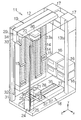
図1は本発明の一実施形態に係るライブラリ装置すなわち磁気テープライブラリ装置11の構造を概略的に示す。この磁気テープライブラリ装置11は箱形の筐体12を備える。筐体12には、例えば床面から立ち上がる直方体の内部空間が区画される。この内部空間には複数の収納棚13a、13bが組み込まれる。1対の収納棚13a(一方は図示されず)は例えば所定の直方体空間を隔てて相互に向き合わせられる。収納棚13aでは、床面から垂直に立ち上がる平面すなわち直方体空間の側面に沿って各セル14、14…の開口が配列される。個々のセル14には磁気テープカートリッジ15といった収納物すなわち記録媒体が収納される。磁気テープカートリッジ15には例えばLTO(Linear Tape−Open)カートリッジが用いられればよい。
FIG. 1 schematically shows the structure of a library apparatus, that is, a magnetic
収納棚13a同士の間で直方体空間には収納棚13bが向き合わせられる。この収納棚13bには例えば4台の記録媒体駆動装置すなわち磁気テープ駆動装置16が組み込まれる。磁気テープ駆動装置16のスロットは、床面から垂直に立ち上がる平面すなわち直方体空間の側面に沿って配置される。磁気テープ駆動装置16は磁気テープカートリッジ15内の磁気テープに磁気情報を書き込むことができる。同時に、磁気テープ駆動装置16は磁気テープカートリッジ15内の磁気テープから磁気情報を読み出すことができる。磁気情報の書き込みや読み出しにあたって磁気テープカートリッジ15は磁気テープ駆動装置16のスロットに対して出し入れされる。磁気テープ駆動装置16内では、磁気テープカートリッジ15内の磁気テープは磁気テープカートリッジ15内のリールから磁気テープ駆動装置16のリールに巻き取られる。
Between the
ここで、直方体空間には三次元座標系すなわちxyz座標系が設定される。このxyz座標系のy軸は床面に垂直に設定される。収納棚13aでは垂直方向すなわちy軸に平行に1列にセル14が配列される。同時に、xyz座標系のz軸は1対の収納棚13aに平行に水平方向に延びる。収納棚13aでは水平方向すなわちz軸に平行に複数列にわたってセル14は横切られる。xyz座標系のx軸は収納棚13bに平行に水平方向に延びる。収納棚13bでは水平方向すなわちx軸に平行に磁気テープ駆動装置16は横切られる。
Here, a three-dimensional coordinate system, that is, an xyz coordinate system is set in the rectangular parallelepiped space. The y axis of this xyz coordinate system is set perpendicular to the floor surface. In the
筐体12の内部空間には例えば2つの収納箱17、17が組み込まれる。一方の収納箱17にはライブラリ制御ボードおよび第1制御ボードが組み込まれる。他方の収納箱17には、同様に、第2制御ボードが組み込まれる。ライブラリ制御ボードには外部のホストコンピュータ(図示されず)が接続される。ホストコンピュータから入力されるデータや指令に基づきライブラリ制御ボードや第1および第2制御ボードでは様々な処理が実行される。
For example, two
筐体12の直方体空間には第1および第2搬送ロボット18、19が組み込まれる。第1および第2搬送ロボット18、19は、第1および第2収納棚13a、13bに対して相対変位する第1および第2ロボットハンド21、22を備える。第1および第2ロボットハンド21、22は情報の書き込みや読み出しにあたって個々のセル14、14…と磁気テープ駆動装置16との間で磁気テープカートリッジ15を搬送することができる。こういった搬送にあたって磁気テープカートリッジ15はスロット23から第1および第2ロボットハンド21、22内に取り込まれる。磁気テープカートリッジ15の受け渡しにあたって第1および第2ロボットハンド21、22は個々のセル14、14…ごとにセル14、14…の開口にスロット23を向き合わせることができる。同様に、第1および第2ロボットハンド21、22は個々の磁気テープ駆動装置16ごとに磁気テープ駆動装置16のスロットにスロット23を向き合わせることができる。第1および第2ロボットハンド21、22の詳細は後述される。
First and
第1搬送ロボット18では第1ロボットハンド21に位置決め機構24が連結される。この位置決め機構24は、床面から垂直方向に立ち上がる支持部材すなわち第1支軸25を備える。第1支軸25には垂直方向に延びる第1レール26が固定される。第1レール26には支持体すなわち案内部材27が連結される。案内部材27には第1レールベース28が連結される。案内部材27や第1レールベース28は1対の収納棚13aに平行に水平方向に延びる。第1レールベース28は1対の収納棚13a、13aから均等な距離すなわち中間位置に配置される。
In the
案内部材27および第1レールベース28は第1レール26に沿って上下方向すなわちy軸に平行に移動することができる。こういった移動の実現にあたって案内部材27には任意の駆動機構が連結される。駆動機構は、例えば、先端で案内部材27に結合されるベルトと、ベルトを巻き上げる巻き上げ機とから構成されればよい。巻き上げ機には例えば電動モータといった動力源が組み込まれる。こうしたy軸用電動モータには例えばステッピングモータが用いられればよい。
The
同様に、第2搬送ロボット19では第2ロボットハンド22に位置決め機構29が連結される。この位置決め機構29は、床面から垂直方向に立ち上がる支持部材すなわち第2支軸31を備える。第2支軸31には垂直方向に延びる第1レール32が固定される。第1レール32には支持体すなわち案内部材33が連結される。案内部材33には第1レールベース34が連結される。案内部材33や第1レールベース34は1対の収納棚13aに平行に水平方向に延びる。第1レールベース34は1対の収納棚13a、13aから均等な距離すなわち中間位置に配置される。
Similarly, a
案内部材33および第1レールベース34は、前述の第1レールベース28と同様に、第1レール32に沿って上下方向すなわちy軸に平行に移動することができる。こういった移動の実現にあたって案内部材33には任意の駆動機構が連結される。駆動機構は、例えば、先端で案内部材33に結合されるベルトと、ベルトを巻き上げる巻き上げ機とから構成されればよい。巻き上げ機には例えば電動モータといった動力源が組み込まれる。こうしたy軸用電動モータには例えばステッピングモータが用いられればよい。案内部材27、33や第1レールベース28、34は垂直方向すなわちy軸方向に配列される。第2搬送ロボット19の第1レールベース34は第1搬送ロボット18の第1レールベース28の上方で垂直方向に移動する。
The
第1レールベース28、34には第2レール35が組み込まれる。第2レール35は収納棚13aに平行に水平方向に延びる。第2レール35には第2レールベース36が連結される。第2レールベース36は収納棚13bに平行に水平方向に延びる。第2レールベース36は第2レール35に沿って水平方向すなわちz軸に平行に移動することができる。こういった移動の実現にあたって第2レールベース36には任意の駆動機構が連結される。駆動機構は、例えば、第2レールベース36に結合されつつ第1レールベース28、34上で1対のプーリに巻き付けられる環状ベルトと、一方のプーリの回転を制御する動力源とから構成されればよい。動力源には電動モータが用いられればよい。こうしたz軸用電動モータには例えばステッピングモータが用いられればよい。
A
第2レールベース36には1対の第3レール37、37が組み込まれる。第3レール37は収納棚13bに平行に水平方向に延びる。第3レール37には前述の第1および第2ロボットハンド21、22が連結される。したがって、第1および第2ロボットハンド21、22は第3レール37に沿って水平方向すなわちx軸に平行に移動することができる。同時に、第1および第2ロボットハンド21、22は第3レール37上で任意の垂直軸すなわちy軸に平行な回転軸回りで回転することができる。こういった移動および回転の実現にあたって第3レール37、37には台座(図示されず)が連結される。台座は第3レール37、37の案内に基づき水平方向すなわちx軸に平行に移動することができる。こういった移動の実現にあたって台座には任意の駆動機構が連結される。駆動機構は、例えば、台座に結合されつつ第2レールベース36上で1対のプーリに巻き付けられる環状ベルトと、一方のプーリの回転を制御する動力源とから構成されればよい。動力源には電動モータが用いられればよい。こうしたx軸用電動モータには例えばステッピングモータが用いられればよい。第1および第2ロボットハンド21、22は台座上に搭載される。第1および第2ロボットハンド21、22は垂直軸回りで回転自在に台座に連結される。ロボットハンド21、22の回転の実現にあたってロボットハンド21、22には任意の駆動機構が連結される。駆動機構は、例えば、ロボットハンド21、22の回転軸および台座上のプーリに巻き付けられる環状ベルトと、プーリの回転を制御する動力源とから構成されればよい。動力源には電動モータが用いられればよい。こうした回転用電動モータには例えばステッピングモータが用いられればよい。
A pair of
以上のような磁気テープライブラリ装置11では、xyz座標系上の三次元座標値と、回転軸回りの回転角とに基づき個々のセル14、14…の位置は特定される。三次元座標値に基づき第1および第2搬送ロボット18、19の第1および第2ロボットハンド21、22は位置決めされる。同時に、回転角に基づき第1および第2ロボットハンド21、22の向きは決定される。第1制御ボードは、個々のセル14に設定された三次元座標値および回転角に基づき第1ロボットハンド21の位置決めおよび回転を制御する。同様に、第2制御ボードは、個々のセル14ごとに三次元座標値および回転角に基づき第2ロボットハンド22の位置決めおよび回転を制御する。こうして第1および第2ロボットハンド21、22の位置決めおよび回転が制御されると、第1および第2ロボットハンド21、22は対応するセル14の開口に正確にスロット23を向き合わせることができる。
In the magnetic
図2に示されるように、第1および第2ロボットハンド21、22は作動領域41内でセル14、14…に対して位置決めされる。作動領域41内では第1および第2ロボットハンド21、22はいずれかのセル14、14…に対してスロット23を向き合わせることができる。その一方で、この磁気テープライブラリ装置11では第1および第2ロボットハンド21、22に対して所定の待避域42、43が設定される。第2ロボットハンド22には作動領域41の上限に隣接して待避域43が設定される。このとき、第2搬送ロボット19の第1レールベース34は第1レール32の上限位置に位置決めされる。こうして第2ロボットハンド22が待避域43に位置決めされると、第2ロボットハンド22は作動領域41から離脱する。その結果、第1ロボットハンド21は作動領域41内で全てのセル14に対して位置決めされることができる。こうして作動領域41および待避域43で第2ロボットハンド22の可動範囲は規定される。
As shown in FIG. 2, the first and second robot hands 21, 22 are positioned with respect to the
同様に、第1ロボットハンド21には作動領域41の下限に隣接して待避域42が設定される。このとき、第1搬送ロボット18の第1レールベース28は第1レール26の下限位置に位置決めされる。こうして第1ロボットハンド21が待避域42に位置決めされると、第1ロボットハンド21は作動領域41から離脱する。その結果、第2ロボットハンド22は作動領域41内で全てのセル14に対して位置決めされることができる。こうして作動領域41および待避域42で第1ロボットハンド21の可動範囲は規定される。なお、この磁気テープライブラリ装置11では収納棚13a、13b同士が相互に近接して配置されることから、特定の三次元座標値および回転角で第1および第2ロボットハンド21、22は収納棚13a、13bに接触する。こういった三次元座標値および回転角は動作中の第1および第2ロボットハンド21、22の可動範囲から外される。
Similarly, the
この磁気テープライブラリ装置11では、通常、ライブラリ制御ボードの指示に基づき第1搬送ロボット18が動作する。第1ロボットハンド21はセル14、14…と磁気テープ駆動装置16、16…との間で磁気テープカートリッジ15を搬送する。例えば作動領域41内で第1ロボットハンド21が故障すると、ライブラリ制御ボードは第2搬送ロボット19の動作を指示する。第2搬送ロボット19の案内部材33および第1レールベース34は第1レール32に沿って駆動される。第1レールベース28および案内部材27は第1レール26上で駆動機構の拘束から解放されることから、例えば案内部材33が第1搬送ロボット18の案内部材27に接触すると、案内部材33の駆動力に基づき第1レールベース28および案内部材27は第1レール26に沿って搬送される。第2搬送ロボット19の案内部材33および第1レールベース34が作動領域41の下限位置に到達すると、第1搬送ロボット18の第1レールベース28は可動範囲の下限位置に位置決めされる。こうして第1ロボットハンド21は待避域42に押し出される。その後、第2ロボットハンド22は、第1ロボットハンド21に代わって、セル14、14…と磁気テープ駆動装置16、16…との間で磁気テープカートリッジ15を搬送する。第2ロボットハンド22が作動領域41内で移動する限り、第2搬送ロボット19と第1搬送ロボット18との干渉は確実に回避されることができる。ここでは、第2搬送ロボット19は本発明に係る搬送機構に相当する。
In the magnetic
こういった場合には、第2搬送ロボット19の動作中に第1搬送ロボット18は修理されることができる。第1搬送ロボット18では例えば第1ロボットハンド21は交換されてもよい。こういった交換後にすぐさま第1搬送ロボット18は第2搬送ロボット19に取って代わってもよい。その他、第2搬送ロボット19の動作は維持されてもよい。第2搬送ロボット19の動作中に第2ロボットハンド22が故障すると、前述と同様に、第2ロボットハンド22は第1搬送ロボット18の働きで待避域43まで押し出される。その後、第1ロボットハンド21は第2ロボットハンド22に取って代わる。第1ロボットハンド21が作動領域41内で移動する限り、第1搬送ロボット18と第2搬送ロボット19との干渉は確実に回避されることができる。このとき、第1搬送ロボット18は本発明に係る搬送機構に相当する。
In such a case, the
次に第1ロボットハンド21の構造を詳述する。図3に示されるように、第1ロボットハンド21は、箱形の筐体45を区画する移動体46を備える。筐体45の前面には前述のスロット23が開口する。図4に示されるように、移動体46の筐体45内には支持部材47が収容される。この支持部材47は1対のガイド軸48に連結される。ガイド軸48は仮想平面すなわち任意の水平面に沿って前後方向に相互に平行に延びる。こうして支持部材47はガイド軸48の案内に基づき前後方向に移動することができる。支持部材47は1対のガイド軸48の間で水平面に沿って前後方向に直交する左右方向に延びる。
Next, the structure of the
支持部材47には駆動機構49が連結される。この駆動機構49は、水平面に直交する垂直軸51回りで回転する回転部材52を備える。回転部材52には、垂直軸51から水平方向にずれた位置に小軸53が配置される。回転部材52が回転すると、小軸53は水平面に沿って垂直軸51回りで円軌道上を移動する。すなわち、移動にあたって小軸53は垂直軸51から一定の距離を維持する。
A
支持部材47には水平面に沿って左右方向に延びる長孔54が形成される。この長孔54に回転部材52上の小軸53は受け入れられる。こうして支持部材47は回転部材52に連結される。長孔54の全長は円軌道の直径以上に設定される。
The
回転部材52には動力源すなわち電動モータ55が連結される。回転部材52には電動モータ55から駆動力が伝達される。駆動力の伝達にあたってベルト伝動や歯車機構が利用されればよい。電動モータ55の回転に応じて回転部材52は垂直軸51回りで回転する。
A power source, that is, an
移動体45の筐体46には規制片56が固定される。この規制片56は回転部材52の移動経路上に配置される。いずれの方向に回転部材52が回転しても回転部材52は規制片56に衝突する。こうして衝突に基づき回転部材52の回転は1周未満に規制される。規制片56は、垂直軸51の軸心を通過する前後方向中心線上で垂直軸51よりも後方に配置される。
A
支持部材47には第1および第2把持爪アセンブリ57a、57bが搭載される。個々の把持爪アセンブリ57a、57bは枢軸58回りで回転自在に支持部材47に連結される。枢軸58は水平面に直交する垂直方向に延びる。第1把持爪アセンブリ57aは第2把持爪アセンブリ57bの枢軸58に向かって左右方向に延びる第1腕部材61を備える。同様に、第2把持爪アセンブリ57bは第1把持爪アセンブリ57aの枢軸58に向かって左右方向に延びる第2腕部材62を備える。第1腕部材61の先端には連結軸63が固定される。連結軸63は垂直方向に直立する。その一方で、第2腕部材62の先端には左右方向に延びる長孔64が形成される。第2腕部材62の先端が第1腕部材61の先端に重ね合わせられると、連結軸63は長孔64に受け入れられる。こうして腕部材61、62の先端同士は連結される。連結軸63は枢軸58、58同士の中間位置に配置される。
First and second
第1および第2腕部材61、62にはそれぞれ把持爪65、66が取り付けられる。把持爪65、66は第1および第2腕部材61、62から前方に延びる。把持爪65、66同士は所定の間隔で左右方向に離隔する。把持爪65、66の先端にはフック67が形成される。フック67は把持爪65、66から内側に折れ曲がる。把持爪65、66は例えば1枚の金属板から打ち抜き成型されればよい。把持爪65、66は水平面に直交する直立姿勢に維持されればよい。
Holding
第1および第2腕部材61、62は、基準位置に先端を配置させる後退位置と、基準位置よりも前方に先端を配置させる前進位置との間で枢軸58回りに揺動することができる。第1および第2腕部材61、62が前進位置に到達すると、フック67、67同士の間隔は磁気テープカートリッジ15の幅よりも増大する。したがって、磁気テープカートリッジ15はフック67、67同士の間に進入することができる。第1および第2腕部材61、62が前進位置から後退位置に向かって移動すると、フック67、67同士は互いに接近する。こうして把持爪65、66の開閉動作は実現される。
The first and
支持部材47と第2腕部材62との間には弾性伸縮部材すなわち収縮ばね68が接続される。この収縮ばね68は後退位置に向かって第2腕部材62を引っ張る。第2腕部材62は収縮ばね68の弾性収縮力で後退位置に保持される。こうして第2腕部材62が引っ張られると、連結軸63の働きで同時に第1腕部材61は後退位置に保持される。把持爪65、66は閉じ位置に保持される。
An elastic elastic member, that is, a
第1腕部材61にはカム部材69が取り付けられる。カム部材69は第1腕部材61に一体化されればよい。カム部材69には、第1腕部材61の根本から先端に向かって広がる第1カム面71と、第1カム面71の先端からさらに第1腕部材61の先端に向かって広がる第2カム面72とが形成される。第1および第2カム面71、72は水平面に直立する。第1腕部材61が後退位置に位置決めされると、第1および第2カム面71、72は長孔54に突き出る。このとき、第1カム面71は、第1腕部材61の先端に向かうにつれて長孔54の輪郭から徐々に張り出し量を増大させる。反対に、第2カム面72は、第1腕部材61の先端に向かうにつれて長孔54の輪郭から徐々に張り出し量を減少させる。第1カム面71は第2カム面72よりも左右方向に大きな広がりを有する。すなわち、第1カム面71の張り出し量は緩やかな勾配で増加する一方、第2カム面72の張り出し量は急激な勾配で減少する。
A
いま、第1ロボットハンド21がセル14に磁気テープカートリッジ15を取りにいく場面を想定する。移動体46の筐体45内では支持部材47は待機位置に位置決めされる。このとき、第1および第2腕部材61、62は収縮ばね68の働きで後退位置に保持される。したがって、把持爪65、66は閉じ位置に配置される。小軸53は長孔54内で長孔54の第1水平端すなわち左端と第1カム面71との間に配置される。
Assume that the
第1ロボットハンド21がセル14に向き合わせられると、図5に示されるように、電動モータ55の働きで回転部材52は垂直軸51回りで前進方向に回転する。回転部材52の回転に伴って小軸53は前進していく。支持部材47と小軸53との間では前後方向に相対移動は規制されることから、小軸53の前進に応じて支持部材47は前進する。このとき、小軸53の左右方向移動は長孔54内で許容される。小軸53は長孔54の第1水平端と第1カム面71との間で移動する。
When the
その後、さらに回転部材52が回転すると、小軸53は長孔54内で第1水平端から第2水平端すなわち右端に向かって移動し始める。その結果、図6に示されるように、小軸53は第1腕部材61上の第1カム面71に接触する。長孔54内で第1カム面71の張り出し量は徐々に増加することから、小軸53の移動は枢軸58回りで第1腕部材61を駆動する。第1腕部材61は収縮ばね68の弾性収縮力に逆らって枢軸58回りで前方に揺動する。こうして枢軸58回りで連結軸63が移動すると、同様に枢軸58回りで前方に第2腕部材62は揺動する。その結果、把持爪65、66同士は相互に離隔していく。同時に、例えば図7からも明らかなように、把持爪65、66は筐体45のスロット23から外側に突き出る。把持爪65、66のフック67、67同士の間にセル14内の磁気テープカートリッジ15は進入する。
Thereafter, when the rotating
さらに回転部材52が回転し続けると、小軸53およびカム部材69の接触は第1カム面71から第2カム面72に移行する。小軸53が第2カム面72を通過すると、図8に示されるように、小軸53が左右方向中央位置に到達する。支持部材47は最前位置に位置決めされる。このとき、収縮ばね68の働きで第1および第2腕部材61、62は瞬時に後退位置に復帰する。その結果、把持爪65、66のフック67、67同士は相互に接近する。こうして磁気テープカートリッジ15は把持爪65、66同士の間に挟み込まれる。フック67は磁気テープカートリッジ15の受け入れ溝に進入する。把持爪65、66には収縮ばね68から弾性収縮力が作用する。磁気テープカートリッジ15はその弾性収縮力に基づき第1ロボットハンド21に保持される。
When the rotating
その後、回転部材52は回転し続ける。図9に示されるように、小軸53は長孔54内で左右方向中央位置から第2水平端に向かって移動する。支持部材47は徐々に後退していく。その結果、把持爪65、66はスロット23内に取り込まれていく。磁気テープカートリッジ15はスロット23内に引き込まれる。
Thereafter, the rotating
回転部材52は規制片56に接触するまで回転を維持する。図10に示されるように、回転部材52が規制片56に接触すると、支持部材47は前後方向に最大限に後退する。こうして支持部材47の後退位置は確立される。磁気テープカートリッジ15は筐体45内に収容される。その後、第1ロボットハンド21は磁気テープカートリッジ15の搬送を開始する。
The rotating
磁気テープカートリッジ15の排出にあたって回転部材52は前述と反対向きに垂直軸51回りに回転する。回転部材52の回転に伴い小軸53は前進する。小軸53が最大限に前進すると、図8に示されるように、支持部材47は最大限に前進する。小軸53は第2カム面72に接触する。回転部材52が回転し続けると、小軸53は長孔54内で左右方向中央位置から第1水平端に向かって移動する。小軸53の移動は枢軸58回りで第1腕部材61を駆動する。第1腕部材61は収縮ばね68の弾性収縮力に逆らって枢軸58回りで前方に揺動する。こうして枢軸58回りで連結軸63が移動すると、同様に枢軸58回りで前方に第2腕部材62は揺動する。その結果、把持爪65、66同士は相互に離隔していく。その結果、把持爪65、66のフック67は磁気テープカートリッジ15から離脱する。
When the
その後、回転部材52の回転に従って支持部材47は徐々にスロット23内に引き込まれる。その結果、把持爪65、66同士の間の空間から磁気テープカートリッジ15は離脱していく。同時に、把持爪65、66のフック67同士は接近していく。把持爪65、66が完全に磁気テープカートリッジ15すなわちセル14から後退すると、把持爪65、66は閉じ位置に到達する。その後、回転部材52の回転に伴って支持部材47は筐体45内で待機位置に位置決めされる。
Thereafter, the
以上のような把持爪アセンブリ57a、57bでは第1および第2腕部材61、62と把持爪65、66との間に逃げ機構74が組み込まれる。把持爪アセンブリ57bでは、図11に示されるように、逃げ機構74は第2腕部材62の前面に固定される取り付け補助部材75を備える。固定にあたって例えばねじ76は用いられる。
In the
取り付け補助部材75には、第2腕部材62の前面から前方に延びる支持片77が形成される。この支持片77に、水平面に沿って左右方向に延びる回転軸78回りで揺動自在に把持爪66が取り付けられる。把持爪66には当該回転軸78に平行に延びるストッパ79が形成される。回転軸78回りで規定されるストッパ79の移動経路は支持片77に交差する。ストッパ79と支持片77との接触に基づき回転軸78回りで把持爪66の回転は規制される。こうして把持爪66の基準姿勢は確立される。この基準姿勢では把持爪66の先端すなわちフック67は最大限に前方に配置される。
A
図12に示されるように、支持片77にはブッシュ81が固定される。このブッシュ81は本発明に係る支軸として機能する。ブッシュ81の固定にあたってねじ82が支持片77にねじ込まれる。ねじ82の頭と支持片77との間にブッシュ81は挟み込まれる。ブッシュ81にはねじ82の頭と支持片77との間で把持爪66が装着される。把持爪66にはブッシュ81を受け入れる貫通孔83が形成される。同様に、ブッシュ81回りで把持爪66と支持片77との間には捻りコイルばね84が装着される。この捻りコイルばね84は回転軸78すなわちブッシュ81回りで一方向に駆動力を発揮する。この一方向の駆動力に応じてフック67は下向きに移動することができる。この駆動力すなわち弾性捻り力に基づき把持爪66は基準姿勢に保持される。支持片77と捻りコイルばね84との間や、捻りコイルばね84と把持爪66との間、把持爪66とねじ82の頭との間にはそれぞれスペーサ85が挿入される。なお、把持爪アセンブリ57aでは逃げ機構は同様に構成される。
As shown in FIG. 12, a
いま、例えば図13に示されるように、第1ロボットハンド21の故障時に第1ロボットハンド21の搬送にあたって把持爪66がセル14やセル14内の磁気テープカートリッジ15に接触する場面を想定する。ここでは、図14に示されるように、把持爪66とセル14との接触に拘わらず第1ロボットハンド21の搬送は継続される。すなわち、第2搬送ロボット19は第1レール26に沿って第1搬送ロボット18の第1レールベース28や案内部材27を駆動する。第1ロボットハンド21には下向きに駆動力が作用する。このとき、図15に示されるように、把持爪66はセル14の反力で回転軸78回りに上向きに回転する。
Now, for example, as shown in FIG. 13, it is assumed that the
図16に示されるように、把持爪66の直立姿勢が確立されると、把持爪66は完全にセル14から離脱する。したがって、第1ロボットハンド21は下向きに移動し続けることができる。こうして把持爪66と磁気テープカートリッジ15やセル14との干渉は回避される。図17に示されるように、把持爪66がセル14を通り過ぎると、把持爪66は捻りコイルばね84の働きで基準姿勢に復帰する。こうして第1ロボットハンド21は確実に待避域42に辿り着くことができる。
As shown in FIG. 16, when the upright posture of the
(付記1) 複数のセルを含む収納棚と、移動体と、所定の待避域に隣接する作動領域内でセルに対して移動体を位置決めする位置決め機構と、移動体に搭載されて、任意の水平面に沿って相互に接近離隔する1対の把持爪と、待避域に向かって移動体を駆動する搬送機構と、搬送機構が待避域に向かって移動体を搬送する際に、把持爪の移動経路上の物体から把持爪を回避させる逃げ機構とを備えることを特徴とするライブラリ装置。 (Supplementary Note 1) A storage shelf including a plurality of cells, a moving body, a positioning mechanism that positions the moving body with respect to the cells within an operation area adjacent to a predetermined retraction area, and an arbitrary mounted on the moving body. A pair of gripping claws that are close to and away from each other along a horizontal plane, a transport mechanism that drives the moving body toward the retracted area, and the movement of the gripping claws when the transport mechanism transports the moving body toward the retracted area. A library apparatus comprising: an escape mechanism that avoids a gripping claw from an object on a path.
(付記2) 付記1に記載のライブラリ装置において、前記搬送機構は、バックアップ用移動体と、前記作動範囲内でセルに対してバックアップ用移動体を位置決めするバックアップ用位置決め機構とを備えることを特徴とするライブラリ装置。 (Additional remark 2) The library apparatus of Additional remark 1 WHEREIN: The said conveyance mechanism is provided with the backup moving body and the backup positioning mechanism which positions the backup moving body with respect to a cell within the said operation range. Library device.
(付記3) 付記2に記載のライブラリ装置において、前記移動体に搭載されて、任意の仮想平面に沿って最前位置および後退位置の間で前後方向に移動する支持部材と、支持部材に搭載されて、当該仮想平面に沿って前後方向に直交する左右方向に延びる回転軸回りで回転自在に前記把持爪を支持部材に連結する支軸と、支持部材に搭載されて、当該左右方向に把持爪同士を相互に接近離隔させる駆動機構とをさらに備えることを特徴とするライブラリ装置。 (Supplementary note 3) In the library apparatus according to supplementary note 2, the support device is mounted on the movable body and moves in the front-rear direction between the foremost position and the retracted position along an arbitrary virtual plane, and is mounted on the support member. And a support shaft for connecting the gripping claw to the support member so as to be rotatable about a rotation axis extending in the left-right direction orthogonal to the front-rear direction along the virtual plane, and a gripping claw mounted on the support member and extending in the left-right direction. A library apparatus, further comprising: a drive mechanism that moves them closer to and away from each other.
(付記4) 付記3に記載のライブラリ装置において、前記支軸回りで一方向に前記把持爪を回転させる駆動力を発揮する弾性部材と、当該一方向に回転する把持爪を受け止め最大限に前方に把持爪の先端を配置させるストッパとをさらに備えることを特徴とするライブラリ装置。 (Supplementary Note 4) In the library device according to Supplementary Note 3, an elastic member that exhibits a driving force that rotates the gripping claw in one direction around the support shaft and a gripping claw that rotates in the one direction are received to the maximum extent possible. A library apparatus, further comprising a stopper for disposing the tip of the gripping claw on the top.
(付記5) 移動体と、移動体に搭載されて、任意の仮想平面に沿って最前位置および後退位置の間で前後方向に移動する支持部材と、支持部材に搭載されて、当該仮想平面に沿って前後方向に直交する左右方向に離隔して配置される1対の把持爪と、支持部材に搭載されて、当該左右方向に把持爪同士を相互に接近させる駆動機構と、支持部材に搭載されて、当該左右方向に延びる回転軸回りで把持爪の回転を許容する逃げ機構とを備えることを特徴とするライブラリ装置用ロボットハンド。 (Supplementary Note 5) A moving body, a supporting member mounted on the moving body and moving in the front-rear direction between the foremost position and the retracted position along an arbitrary virtual plane, mounted on the supporting member, and mounted on the virtual plane A pair of gripping claws that are spaced apart from each other in the left-right direction perpendicular to the front-rear direction, a drive mechanism that is mounted on the support member and that causes the gripping claws to approach each other in the left-right direction, and mounted on the support member And a relief mechanism for allowing rotation of the gripping claw around the rotation axis extending in the left-right direction.
(付記6) 付記5に記載のライブラリ装置用ロボットハンドにおいて、前記逃げ機構は、前記左右方向に延びて回転自在に前記把持爪を支持する支軸と、支軸回りで一方向に把持爪を回転させる駆動力を発揮する弾性部材と、当該一方向に回転する把持爪を受け止め最大限に前方に把持爪の先端を配置させるストッパとを備えることを特徴とするライブラリ装置用ロボットハンド。
(Appendix 6) In the robot hand for a library apparatus according to
11 ライブラリ装置、13a 収納棚、14 セル、18,19 搬送機構(第1および第2搬送ロボット)、24,29 位置決め機構(バックアップ用位置決め機構)、41 作動領域、42(43) 待避域、45 移動体(バックアップ用移動体)、47 支持部材、49 駆動機構、65,66 把持爪、74 逃げ機構、79 ストッパ、81 支軸(ブッシュ)、84 弾性部材(捻りコイルばね)。 11 Library device, 13a Storage shelf, 14 cells, 18, 19 Transport mechanism (first and second transport robots), 24, 29 Positioning mechanism (backup positioning mechanism), 41 Operating area, 42 (43) Retreat area, 45 Moving body (backup moving body), 47 support member, 49 drive mechanism, 65, 66 gripping claw, 74 escape mechanism, 79 stopper, 81 spindle (bush), 84 elastic member (torsion coil spring).
Claims (3)
Priority Applications (4)
| Application Number | Priority Date | Filing Date | Title |
|---|---|---|---|
| JP2006045005A JP4303253B2 (en) | 2006-02-22 | 2006-02-22 | Library device and robot hand for library device |
| US11/383,344 US7753638B2 (en) | 2006-02-22 | 2006-05-15 | Robot hand having swaying mechanism in library apparatus |
| CN2006100827700A CN101024284B (en) | 2006-02-22 | 2006-05-25 | Robot hand having swaying mechanism in library apparatus |
| KR1020060048471A KR100805023B1 (en) | 2006-02-22 | 2006-05-30 | Robot hand for library unit and library unit |
Applications Claiming Priority (1)
| Application Number | Priority Date | Filing Date | Title |
|---|---|---|---|
| JP2006045005A JP4303253B2 (en) | 2006-02-22 | 2006-02-22 | Library device and robot hand for library device |
Publications (2)
| Publication Number | Publication Date |
|---|---|
| JP2007226873A JP2007226873A (en) | 2007-09-06 |
| JP4303253B2 true JP4303253B2 (en) | 2009-07-29 |
Family
ID=38428349
Family Applications (1)
| Application Number | Title | Priority Date | Filing Date |
|---|---|---|---|
| JP2006045005A Expired - Fee Related JP4303253B2 (en) | 2006-02-22 | 2006-02-22 | Library device and robot hand for library device |
Country Status (4)
| Country | Link |
|---|---|
| US (1) | US7753638B2 (en) |
| JP (1) | JP4303253B2 (en) |
| KR (1) | KR100805023B1 (en) |
| CN (1) | CN101024284B (en) |
Families Citing this family (18)
| Publication number | Priority date | Publication date | Assignee | Title |
|---|---|---|---|---|
| US8134799B1 (en) * | 2004-04-06 | 2012-03-13 | Oracle America, Inc. | Gripper assembly for data storage system |
| AT503427B1 (en) * | 2006-08-03 | 2007-10-15 | Katt Logistik Gmbh | Method for loading and unloading goods e.g., for storage logistics, involves lowering loading platform when receiving goods |
| JP5104146B2 (en) * | 2007-09-13 | 2012-12-19 | 富士通株式会社 | Tape library device |
| WO2010001461A1 (en) * | 2008-07-01 | 2010-01-07 | 富士通株式会社 | Library device |
| US20120093619A1 (en) * | 2009-05-19 | 2012-04-19 | Venture Corporation Limited | Tape cartridge handler |
| JP5842514B2 (en) | 2011-09-29 | 2016-01-13 | 富士通株式会社 | Library apparatus and storage medium conveyance control method |
| JP2014203492A (en) * | 2013-04-05 | 2014-10-27 | ソニー株式会社 | Recording medium transfer mechanism and recording medium changer |
| JP6149622B2 (en) * | 2013-09-06 | 2017-06-21 | 富士通株式会社 | Library apparatus and article conveying apparatus |
| WO2016120930A1 (en) * | 2015-01-30 | 2016-08-04 | パナソニックIpマネジメント株式会社 | Robotic transfer device |
| CN105564876A (en) * | 2015-12-11 | 2016-05-11 | 黄常宇 | Overrun-preventing intelligent storage logistics system |
| CN112093399B (en) * | 2016-02-18 | 2022-07-26 | 株式会社大福 | Article conveying device |
| US10510372B1 (en) * | 2017-06-02 | 2019-12-17 | Amazon Technologies, Inc. | Mechanical retention and retrieval for tape storage cartridge |
| US10589423B2 (en) * | 2018-06-18 | 2020-03-17 | Shambhu Nath Roy | Robot vision super visor for hybrid homing, positioning and workspace UFO detection enabling industrial robot use for consumer applications |
| CN108972126B (en) * | 2018-09-12 | 2024-03-08 | 珠海格力智能装备有限公司 | Feed bin and flange processingequipment who has it |
| CN111301551B (en) * | 2020-02-22 | 2021-05-25 | 杭州电子科技大学 | A fully magnetic control robot based on origami art with magnetic rod structure and its magnetic control method |
| CN111958614A (en) * | 2020-08-18 | 2020-11-20 | 安徽师范大学 | A library intelligent service robot and its matching bookshelf |
| CN113804474B (en) * | 2021-10-14 | 2024-07-12 | 苏州苏试试验集团股份有限公司 | Swing test bed |
| CN114261674A (en) * | 2022-01-28 | 2022-04-01 | 珠海世纪鼎利科技股份有限公司 | Automatic counting device for seal card |
Family Cites Families (25)
| Publication number | Priority date | Publication date | Assignee | Title |
|---|---|---|---|---|
| US4132318A (en) * | 1976-12-30 | 1979-01-02 | International Business Machines Corporation | Asymmetric six-degree-of-freedom force-transducer system for a computer-controlled manipulator system |
| US4344729A (en) * | 1980-02-08 | 1982-08-17 | Bell And Howell Company | Break-away device |
| IT1143543B (en) * | 1981-04-13 | 1986-10-22 | Comau Spa | MECHANIZED WAREHOUSE |
| GB2198413B (en) * | 1986-11-20 | 1990-01-17 | Shimizu Construction Co Ltd | Transporting robot for semiconductor wafers |
| US4827463A (en) * | 1987-04-07 | 1989-05-02 | Mitsubishi Denki Kabushiki Kaisha | Disc memory device |
| US4815055A (en) * | 1987-04-17 | 1989-03-21 | Access Corporation | Data medium storage and retrieval devices |
| JP2618395B2 (en) | 1987-06-24 | 1997-06-11 | 日本電信電話株式会社 | Cartridge handling mechanism |
| US4913617A (en) * | 1988-07-20 | 1990-04-03 | Martin Marietta Energy Systems, Inc. | Remote tong/tool latch and storage bracket for an advanced servo-manipulator |
| US5379229A (en) * | 1992-06-18 | 1995-01-03 | Communications Test Design, Inc. | Automated storage and retrieval system |
| JPH0652611A (en) | 1992-07-30 | 1994-02-25 | Hitachi Electron Eng Co Ltd | Control system for switching robot hand |
| JP2944861B2 (en) | 1993-07-22 | 1999-09-06 | 帝国インキ製造株式会社 | Scratch coloring printing method and scratch coloring printing body |
| US5805561A (en) * | 1994-01-18 | 1998-09-08 | Sony Corporation | Cartridge engagement system for optical disk cartridges having a positionable carriage |
| US5449262A (en) * | 1994-05-26 | 1995-09-12 | Diamond Machine Co. | Inserter/extractor used with carousel of storage bins |
| US5544146B1 (en) * | 1994-08-24 | 1998-03-03 | Hewlett Packard Co | Cartridge handling system |
| JPH08195013A (en) | 1995-01-19 | 1996-07-30 | Nec Eng Ltd | Assembled information recorder |
| US5691859A (en) * | 1995-12-19 | 1997-11-25 | Exabyte Corporation | Drive with features which adjust and actuate cartridge transport and library with such drive |
| JPH10134460A (en) | 1996-10-28 | 1998-05-22 | Fujitsu Ltd | Automatic accessor stopper system for library equipment |
| US5848872A (en) * | 1996-11-15 | 1998-12-15 | Storage Technology Corporation | Apparatus for handling cartridges in a storage library system |
| US5954446A (en) * | 1997-04-11 | 1999-09-21 | Ireland; Randy L. | Breakaway tool coupler for robot arm |
| JPH11162055A (en) * | 1997-11-27 | 1999-06-18 | Matsushita Electric Ind Co Ltd | Cassette changer |
| US6309162B1 (en) * | 1999-05-13 | 2001-10-30 | Hewlett-Packard Company | Data storage system with redundant media handling assemblies |
| US6778351B1 (en) * | 2001-05-18 | 2004-08-17 | Hewlett-Packard Development Company L.P. | System and method of redundant cabling in a media storage system |
| US20040091339A1 (en) * | 2002-11-12 | 2004-05-13 | Kevin Arnal | Multi-media picker assembly |
| US6968257B2 (en) * | 2003-11-21 | 2005-11-22 | International Business Machines Corporation | Continued execution of accessor commands on a restricted multiple accessor path of an automated data storage library |
| JP4095048B2 (en) | 2004-07-28 | 2008-06-04 | 富士通株式会社 | Library device |
-
2006
- 2006-02-22 JP JP2006045005A patent/JP4303253B2/en not_active Expired - Fee Related
- 2006-05-15 US US11/383,344 patent/US7753638B2/en not_active Expired - Fee Related
- 2006-05-25 CN CN2006100827700A patent/CN101024284B/en not_active Expired - Fee Related
- 2006-05-30 KR KR1020060048471A patent/KR100805023B1/en not_active IP Right Cessation
Also Published As
| Publication number | Publication date |
|---|---|
| US7753638B2 (en) | 2010-07-13 |
| US20070196197A1 (en) | 2007-08-23 |
| KR100805023B1 (en) | 2008-02-20 |
| JP2007226873A (en) | 2007-09-06 |
| CN101024284A (en) | 2007-08-29 |
| CN101024284B (en) | 2012-05-30 |
| KR20070084998A (en) | 2007-08-27 |
Similar Documents
| Publication | Publication Date | Title |
|---|---|---|
| JP4303253B2 (en) | Library device and robot hand for library device | |
| US20180304459A1 (en) | Movable closed-chain linkage for robot arm of media element storage library | |
| KR100787327B1 (en) | Transrorting rail unit and connection mechanism in library apparatus | |
| JP4387283B2 (en) | Storage shelf transport mechanism, control method therefor, and control program therefor | |
| US8134799B1 (en) | Gripper assembly for data storage system | |
| JP2011023068A (en) | Housing device, housing method, and library device | |
| JP4210264B2 (en) | Library device | |
| JP4331764B2 (en) | Library device and transport mechanism for library device | |
| US8102617B2 (en) | Method for transporting a tape cartridge within a tape library storage system utilizing a curved rack section and independently rotatable teeth | |
| JP4754656B2 (en) | Library device | |
| JP5979558B2 (en) | Disk drive unit and disk device including the unit | |
| US20110235209A1 (en) | Tape library apparatus | |
| JP5516573B2 (en) | Robot hand and library device | |
| US9218842B2 (en) | Library apparatus and method of reading information of recording medium | |
| JP2014026691A (en) | Magazine chuck | |
| JP4079907B2 (en) | Cassette library device | |
| JPH10261254A (en) | Disk exchange device | |
| JP2005190666A (en) | Tape drive device |
Legal Events
| Date | Code | Title | Description |
|---|---|---|---|
| A977 | Report on retrieval |
Free format text: JAPANESE INTERMEDIATE CODE: A971007 Effective date: 20081027 |
|
| A131 | Notification of reasons for refusal |
Free format text: JAPANESE INTERMEDIATE CODE: A131 Effective date: 20081104 |
|
| A521 | Written amendment |
Free format text: JAPANESE INTERMEDIATE CODE: A523 Effective date: 20090105 |
|
| A131 | Notification of reasons for refusal |
Free format text: JAPANESE INTERMEDIATE CODE: A131 Effective date: 20090203 |
|
| A521 | Written amendment |
Free format text: JAPANESE INTERMEDIATE CODE: A523 Effective date: 20090226 |
|
| TRDD | Decision of grant or rejection written | ||
| A01 | Written decision to grant a patent or to grant a registration (utility model) |
Free format text: JAPANESE INTERMEDIATE CODE: A01 Effective date: 20090421 |
|
| A01 | Written decision to grant a patent or to grant a registration (utility model) |
Free format text: JAPANESE INTERMEDIATE CODE: A01 |
|
| A61 | First payment of annual fees (during grant procedure) |
Free format text: JAPANESE INTERMEDIATE CODE: A61 Effective date: 20090423 |
|
| FPAY | Renewal fee payment (event date is renewal date of database) |
Free format text: PAYMENT UNTIL: 20120501 Year of fee payment: 3 |
|
| R150 | Certificate of patent or registration of utility model |
Free format text: JAPANESE INTERMEDIATE CODE: R150 |
|
| FPAY | Renewal fee payment (event date is renewal date of database) |
Free format text: PAYMENT UNTIL: 20120501 Year of fee payment: 3 |
|
| FPAY | Renewal fee payment (event date is renewal date of database) |
Free format text: PAYMENT UNTIL: 20130501 Year of fee payment: 4 |
|
| FPAY | Renewal fee payment (event date is renewal date of database) |
Free format text: PAYMENT UNTIL: 20130501 Year of fee payment: 4 |
|
| LAPS | Cancellation because of no payment of annual fees |