JP4295511B2 - Photoelectron detection system - Google Patents
Photoelectron detection system Download PDFInfo
- Publication number
- JP4295511B2 JP4295511B2 JP2002566387A JP2002566387A JP4295511B2 JP 4295511 B2 JP4295511 B2 JP 4295511B2 JP 2002566387 A JP2002566387 A JP 2002566387A JP 2002566387 A JP2002566387 A JP 2002566387A JP 4295511 B2 JP4295511 B2 JP 4295511B2
- Authority
- JP
- Japan
- Prior art keywords
- cells
- emitter
- particles
- cell
- target
- Prior art date
- Legal status (The legal status is an assumption and is not a legal conclusion. Google has not performed a legal analysis and makes no representation as to the accuracy of the status listed.)
- Expired - Lifetime
Links
Images


Classifications
-
- G—PHYSICS
- G01—MEASURING; TESTING
- G01N—INVESTIGATING OR ANALYSING MATERIALS BY DETERMINING THEIR CHEMICAL OR PHYSICAL PROPERTIES
- G01N33/00—Investigating or analysing materials by specific methods not covered by groups G01N1/00 - G01N31/00
- G01N33/48—Biological material, e.g. blood, urine; Haemocytometers
- G01N33/50—Chemical analysis of biological material, e.g. blood, urine; Testing involving biospecific ligand binding methods; Immunological testing
- G01N33/53—Immunoassay; Biospecific binding assay; Materials therefor
- G01N33/543—Immunoassay; Biospecific binding assay; Materials therefor with an insoluble carrier for immobilising immunochemicals
- G01N33/554—Immunoassay; Biospecific binding assay; Materials therefor with an insoluble carrier for immobilising immunochemicals the carrier being a biological cell or cell fragment, e.g. bacteria, yeast cells
-
- G—PHYSICS
- G01—MEASURING; TESTING
- G01N—INVESTIGATING OR ANALYSING MATERIALS BY DETERMINING THEIR CHEMICAL OR PHYSICAL PROPERTIES
- G01N21/00—Investigating or analysing materials by the use of optical means, i.e. using sub-millimetre waves, infrared, visible or ultraviolet light
- G01N21/75—Systems in which material is subjected to a chemical reaction, the progress or the result of the reaction being investigated
- G01N21/76—Chemiluminescence; Bioluminescence
-
- G—PHYSICS
- G01—MEASURING; TESTING
- G01N—INVESTIGATING OR ANALYSING MATERIALS BY DETERMINING THEIR CHEMICAL OR PHYSICAL PROPERTIES
- G01N15/00—Investigating characteristics of particles; Investigating permeability, pore-volume or surface-area of porous materials
- G01N15/02—Investigating particle size or size distribution
- G01N15/0205—Investigating particle size or size distribution by optical means
-
- G—PHYSICS
- G01—MEASURING; TESTING
- G01N—INVESTIGATING OR ANALYSING MATERIALS BY DETERMINING THEIR CHEMICAL OR PHYSICAL PROPERTIES
- G01N21/00—Investigating or analysing materials by the use of optical means, i.e. using sub-millimetre waves, infrared, visible or ultraviolet light
- G01N21/01—Arrangements or apparatus for facilitating the optical investigation
- G01N21/03—Cuvette constructions
- G01N21/07—Centrifugal type cuvettes
-
- G—PHYSICS
- G01—MEASURING; TESTING
- G01N—INVESTIGATING OR ANALYSING MATERIALS BY DETERMINING THEIR CHEMICAL OR PHYSICAL PROPERTIES
- G01N21/00—Investigating or analysing materials by the use of optical means, i.e. using sub-millimetre waves, infrared, visible or ultraviolet light
- G01N21/62—Systems in which the material investigated is excited whereby it emits light or causes a change in wavelength of the incident light
- G01N21/63—Systems in which the material investigated is excited whereby it emits light or causes a change in wavelength of the incident light optically excited
- G01N21/64—Fluorescence; Phosphorescence
- G01N21/6428—Measuring fluorescence of fluorescent products of reactions or of fluorochrome labelled reactive substances, e.g. measuring quenching effects, using measuring "optrodes"
-
- G—PHYSICS
- G01—MEASURING; TESTING
- G01N—INVESTIGATING OR ANALYSING MATERIALS BY DETERMINING THEIR CHEMICAL OR PHYSICAL PROPERTIES
- G01N21/00—Investigating or analysing materials by the use of optical means, i.e. using sub-millimetre waves, infrared, visible or ultraviolet light
- G01N21/75—Systems in which material is subjected to a chemical reaction, the progress or the result of the reaction being investigated
-
- G—PHYSICS
- G01—MEASURING; TESTING
- G01N—INVESTIGATING OR ANALYSING MATERIALS BY DETERMINING THEIR CHEMICAL OR PHYSICAL PROPERTIES
- G01N33/00—Investigating or analysing materials by specific methods not covered by groups G01N1/00 - G01N31/00
- G01N33/48—Biological material, e.g. blood, urine; Haemocytometers
- G01N33/50—Chemical analysis of biological material, e.g. blood, urine; Testing involving biospecific ligand binding methods; Immunological testing
- G01N33/53—Immunoassay; Biospecific binding assay; Materials therefor
- G01N33/543—Immunoassay; Biospecific binding assay; Materials therefor with an insoluble carrier for immobilising immunochemicals
- G01N33/54366—Apparatus specially adapted for solid-phase testing
- G01N33/54373—Apparatus specially adapted for solid-phase testing involving physiochemical end-point determination, e.g. wave-guides, FETS, gratings
-
- G—PHYSICS
- G01—MEASURING; TESTING
- G01N—INVESTIGATING OR ANALYSING MATERIALS BY DETERMINING THEIR CHEMICAL OR PHYSICAL PROPERTIES
- G01N33/00—Investigating or analysing materials by specific methods not covered by groups G01N1/00 - G01N31/00
- G01N33/48—Biological material, e.g. blood, urine; Haemocytometers
- G01N33/50—Chemical analysis of biological material, e.g. blood, urine; Testing involving biospecific ligand binding methods; Immunological testing
- G01N33/53—Immunoassay; Biospecific binding assay; Materials therefor
- G01N33/543—Immunoassay; Biospecific binding assay; Materials therefor with an insoluble carrier for immobilising immunochemicals
- G01N33/54393—Improving reaction conditions or stability, e.g. by coating or irradiation of surface, by reduction of non-specific binding, by promotion of specific binding
-
- G—PHYSICS
- G01—MEASURING; TESTING
- G01N—INVESTIGATING OR ANALYSING MATERIALS BY DETERMINING THEIR CHEMICAL OR PHYSICAL PROPERTIES
- G01N33/00—Investigating or analysing materials by specific methods not covered by groups G01N1/00 - G01N31/00
- G01N33/48—Biological material, e.g. blood, urine; Haemocytometers
- G01N33/50—Chemical analysis of biological material, e.g. blood, urine; Testing involving biospecific ligand binding methods; Immunological testing
- G01N33/53—Immunoassay; Biospecific binding assay; Materials therefor
- G01N33/569—Immunoassay; Biospecific binding assay; Materials therefor for microorganisms, e.g. protozoa, bacteria, viruses
- G01N33/56983—Viruses
-
- G—PHYSICS
- G01—MEASURING; TESTING
- G01N—INVESTIGATING OR ANALYSING MATERIALS BY DETERMINING THEIR CHEMICAL OR PHYSICAL PROPERTIES
- G01N33/00—Investigating or analysing materials by specific methods not covered by groups G01N1/00 - G01N31/00
- G01N33/48—Biological material, e.g. blood, urine; Haemocytometers
- G01N33/50—Chemical analysis of biological material, e.g. blood, urine; Testing involving biospecific ligand binding methods; Immunological testing
- G01N33/58—Chemical analysis of biological material, e.g. blood, urine; Testing involving biospecific ligand binding methods; Immunological testing involving labelled substances
- G01N33/582—Chemical analysis of biological material, e.g. blood, urine; Testing involving biospecific ligand binding methods; Immunological testing involving labelled substances with fluorescent label
-
- G—PHYSICS
- G01—MEASURING; TESTING
- G01N—INVESTIGATING OR ANALYSING MATERIALS BY DETERMINING THEIR CHEMICAL OR PHYSICAL PROPERTIES
- G01N21/00—Investigating or analysing materials by the use of optical means, i.e. using sub-millimetre waves, infrared, visible or ultraviolet light
- G01N21/62—Systems in which the material investigated is excited whereby it emits light or causes a change in wavelength of the incident light
- G01N21/63—Systems in which the material investigated is excited whereby it emits light or causes a change in wavelength of the incident light optically excited
- G01N21/64—Fluorescence; Phosphorescence
- G01N21/6428—Measuring fluorescence of fluorescent products of reactions or of fluorochrome labelled reactive substances, e.g. measuring quenching effects, using measuring "optrodes"
- G01N2021/6439—Measuring fluorescence of fluorescent products of reactions or of fluorochrome labelled reactive substances, e.g. measuring quenching effects, using measuring "optrodes" with indicators, stains, dyes, tags, labels, marks
-
- G—PHYSICS
- G01—MEASURING; TESTING
- G01N—INVESTIGATING OR ANALYSING MATERIALS BY DETERMINING THEIR CHEMICAL OR PHYSICAL PROPERTIES
- G01N2201/00—Features of devices classified in G01N21/00
- G01N2201/02—Mechanical
- G01N2201/025—Mechanical control of operations
-
- G—PHYSICS
- G01—MEASURING; TESTING
- G01N—INVESTIGATING OR ANALYSING MATERIALS BY DETERMINING THEIR CHEMICAL OR PHYSICAL PROPERTIES
- G01N2201/00—Features of devices classified in G01N21/00
- G01N2201/06—Illumination; Optics
- G01N2201/061—Sources
-
- Y—GENERAL TAGGING OF NEW TECHNOLOGICAL DEVELOPMENTS; GENERAL TAGGING OF CROSS-SECTIONAL TECHNOLOGIES SPANNING OVER SEVERAL SECTIONS OF THE IPC; TECHNICAL SUBJECTS COVERED BY FORMER USPC CROSS-REFERENCE ART COLLECTIONS [XRACs] AND DIGESTS
- Y10—TECHNICAL SUBJECTS COVERED BY FORMER USPC
- Y10S—TECHNICAL SUBJECTS COVERED BY FORMER USPC CROSS-REFERENCE ART COLLECTIONS [XRACs] AND DIGESTS
- Y10S435/00—Chemistry: molecular biology and microbiology
- Y10S435/808—Optical sensing apparatus
-
- Y—GENERAL TAGGING OF NEW TECHNOLOGICAL DEVELOPMENTS; GENERAL TAGGING OF CROSS-SECTIONAL TECHNOLOGIES SPANNING OVER SEVERAL SECTIONS OF THE IPC; TECHNICAL SUBJECTS COVERED BY FORMER USPC CROSS-REFERENCE ART COLLECTIONS [XRACs] AND DIGESTS
- Y10—TECHNICAL SUBJECTS COVERED BY FORMER USPC
- Y10S—TECHNICAL SUBJECTS COVERED BY FORMER USPC CROSS-REFERENCE ART COLLECTIONS [XRACs] AND DIGESTS
- Y10S436/00—Chemistry: analytical and immunological testing
- Y10S436/805—Optical property
Landscapes
- Health & Medical Sciences (AREA)
- Life Sciences & Earth Sciences (AREA)
- Immunology (AREA)
- Chemical & Material Sciences (AREA)
- Engineering & Computer Science (AREA)
- Physics & Mathematics (AREA)
- Pathology (AREA)
- Analytical Chemistry (AREA)
- Biochemistry (AREA)
- General Health & Medical Sciences (AREA)
- General Physics & Mathematics (AREA)
- Molecular Biology (AREA)
- Biomedical Technology (AREA)
- Hematology (AREA)
- Urology & Nephrology (AREA)
- Cell Biology (AREA)
- Microbiology (AREA)
- Biotechnology (AREA)
- Food Science & Technology (AREA)
- Medicinal Chemistry (AREA)
- Chemical Kinetics & Catalysis (AREA)
- Plasma & Fusion (AREA)
- Nuclear Medicine, Radiotherapy & Molecular Imaging (AREA)
- Virology (AREA)
- Optics & Photonics (AREA)
- Mycology (AREA)
- Tropical Medicine & Parasitology (AREA)
- Dispersion Chemistry (AREA)
- Measuring Or Testing Involving Enzymes Or Micro-Organisms (AREA)
- Investigating, Analyzing Materials By Fluorescence Or Luminescence (AREA)
- Apparatus Associated With Microorganisms And Enzymes (AREA)
- Investigating Or Analysing Materials By The Use Of Chemical Reactions (AREA)
- Photo Coupler, Interrupter, Optical-To-Optical Conversion Devices (AREA)
- Radar Systems Or Details Thereof (AREA)
- Hybrid Cells (AREA)
- Investigating Or Analysing Materials By Optical Means (AREA)
- Sampling And Sample Adjustment (AREA)
- Geophysics And Detection Of Objects (AREA)
- Investigating Or Analysing Biological Materials (AREA)
- Measurement Of The Respiration, Hearing Ability, Form, And Blood Characteristics Of Living Organisms (AREA)
Abstract
Description
関連出願の相互参照
本出願は2001年2月7日に出願された「光電子による検出システム(Optoelectronic Detection System)」という名称の米国特許出願第60/266,977号の恩典を主張するものであり、この出願はその全体において参照として本明細書に組み入れられる。
CROSS-REFERENCE TO RELATED APPLICATIONS This application claims the benefit of 2001 "detection system according to photoelectrons (Optoelectronic Detection System)" filed on February 7 entitled U.S. patent application Ser. No. 60 / 266,977, the The application is incorporated herein by reference in its entirety.
政府関連研究に関する陳述
本発明は米国空軍契約番号第F19628-00-C-0002号からの政府基金を利用して達成された。米国政府は本発明に関して一定の権利を有する。
Statement on Government Related Research This invention was accomplished using a government fund from US Air Force Contract No. F19628-00-C-0002. The United States government has certain rights in this invention.
発明の背景
生物化学兵器の急増、貧者の核兵器により、長期間、環境を監視できる小型、迅速、および高感度な生物因子検出器の必要性が強調されている。戦場条件下では、有用な検出器は特定の生物化学兵器が検出される場合、素早く防御手段を実行できるように、迅速に兵士に警告を発すると思われる。
BACKGROUND OF THE INVENTION The proliferation of biochemical weapons, poor nuclear weapons, has emphasized the need for small, rapid, and sensitive biofactor detectors that can monitor the environment for extended periods of time. Under battlefield conditions, useful detectors will warn soldiers quickly so that if a specific biochemical weapon is detected, they can quickly take defensive measures.
そのような検出器は非軍事的な適用に関しても同様に有用であると思われる。患者における抗生物質耐性細菌の迅速検出は、臨床医がより効果的な治療計画を選択する一助になると思われる。都市の飲料水供給の継続的監視により、病原体の潜在性が早期に警告され、一般大衆への潜在的健康被害に対処するためのより多くの時間が公共事業職員に与えられると思われる。さらに、獣鶏肉検査におけるこれらの検出器の使用により、現在の「抜き取り臭気(poke-and-smell)」検査手順が顕著に改善されると思われる。一般に、そのような検出器はもっぱら医薬(例えば、動物薬)、農業、環境保全(例えば、シックハウス症候群を診断すること)、および食品加工または調整の分野内での分析的および診断的応用に必要とされる。 Such a detector would be equally useful for non-military applications. Rapid detection of antibiotic-resistant bacteria in patients will help clinicians choose more effective treatment plans. Continued monitoring of the city's drinking water supply will warn early on the potential of pathogens and give public service staff more time to deal with potential health hazards to the general public. In addition, the use of these detectors in poultry testing would significantly improve current “poke-and-smell” testing procedures. In general, such detectors are exclusively required for analytical and diagnostic applications within the fields of medicine (e.g. animal medicine), agriculture, environmental conservation (e.g. diagnosing sick house syndrome), and food processing or conditioning. It is said.
全ての脊椎動物は、抗体分子の免疫的多様性の創出により一部の外来性因子(抗原)に対する特異的免疫反応を獲得する。抗体分子は高い特異性をもって抗原に結合する、例えば、それらは細菌、ウイルス、タンパク質、核酸、真菌、原生動物、多細胞寄生虫、またはプリオンのほか、それらの粒子により産生されるもしくは誘導される産物の2つの密接な関連種に差別的に結合できる。 All vertebrates acquire specific immune responses against some foreign factors (antigens) by creating immunodiversity of antibody molecules. Antibody molecules bind antigens with high specificity, for example, they are produced or induced by particles, in addition to bacteria, viruses, proteins, nucleic acids, fungi, protozoa, multicellular parasites, or prions Can differentially bind to two closely related species of products.
抗体は免疫系の重要な構成成分であるB細胞により産生される。抗原はB細胞表面上の抗体との結合により、B細胞サイトゾル中へのカルシウムイオン流入を引き起こす細胞内生化学反応カスケードを誘発し、B細胞を活性化できる。 Antibodies are produced by B cells, an important component of the immune system. Antigens can activate B cells by binding to antibodies on the surface of B cells, triggering an intracellular biochemical cascade that causes calcium ion influx into the B cell cytosol.
抗体構造および機能並びにB細胞活性化の総説に関しては、Paul編, 「基礎免疫学(Fundamental Immunology)」, 第3版., Raven Press, New York (1993)を参照されたい。 For a review of antibody structure and function and B cell activation, see Paul, Ed., “Fundamental Immunology”, 3rd edition, Raven Press, New York (1993).
発明の概要
多様なおよび稀な標的粒子または抗原を検出するために抗体の多様性を利用している装置は、米国特許第6,087,114号および1998年10月9日に出願され、現在、継続中の米国特許出願第09/169,196号に記載されている。
SUMMARY OF THE INVENTIONAn apparatus utilizing antibody diversity to detect diverse and rare target particles or antigens was filed on U.S. Pat.No. 6,087,114 and Oct. 9, 1998 and is currently ongoing. It is described in US patent application Ser. No. 09 / 169,196.
これらの装置には一般的に、センサー細胞(例えば、B細胞または繊維芽細胞)を含む液体培地、光学検出器、および検出対象の標的粒子を受ける液体培地が含まれる。細胞の各々は、その表面上に発現したおよび検出対象の抗原に特異的な受容体(例えば、キメラまたは一本鎖抗体)を有する。受容体への抗原の結合により、化学的または生化学的変化(例えば、カルシウム濃度の増加)を伴うシグナル伝達経路が引き起こされる。細胞はまた、シグナル伝達経路(例えば、サイトゾル中のカルシウム濃度の増加)に応答して光子を放出できる放出体(emitter)分子(例えば、エクオリンまたはindo-1)をそのサイトゾル中に含む。検出器は光子透過性のカバー(例えば、ガラス)により細胞を含む培地から分離できる。このようなカバーは培地を支える、検出器の脆弱な表面を保護する、またはレンズとして使用される役割を果たすことができる。光学検出器、例えば、電荷結合素子(CCD)は受容体が媒介するシグナル伝達経路に応答して細胞から放出される光子を検出することができ、および検出対象の抗原が存在していることを使用者に知らせることができる。装置に使用できる他の光学検出器には、光電子増倍管、フォトダイオード、相補型金属酸化物半導体(CMOS)イメージャ(例えば、http://www.kodak.com/US/en/corp/researchDevelopment/technologyFeatures/cmos.shtmlを参照されたい)、アバランシェフォトダイオード、および画像増強型電荷結合素子(ICCD)(例えば、Photek Ltd., East Sussex, UKから市販されているものを参照されたい)が含まれる。いくつかの態様において、光学検出器は個々の細胞を識別できる。 These devices generally include a liquid medium containing sensor cells (eg, B cells or fibroblasts), an optical detector, and a liquid medium that receives the target particles to be detected. Each of the cells has a receptor (eg, a chimeric or single chain antibody) expressed on its surface and specific for the antigen to be detected. Binding of the antigen to the receptor causes a signaling pathway that involves chemical or biochemical changes (eg, increased calcium concentration). Cells also contain emitter molecules (eg, aequorin or indo-1) in their cytosol that can emit photons in response to signal transduction pathways (eg, an increase in calcium concentration in the cytosol). The detector can be separated from the medium containing the cells by a photon permeable cover (eg glass). Such a cover can serve to support the medium, protect the fragile surface of the detector, or be used as a lens. Optical detectors, such as charge-coupled devices (CCD), can detect photons emitted from cells in response to receptor-mediated signaling pathways, and that the antigen to be detected is present Can inform the user. Other optical detectors that can be used in the instrument include photomultiplier tubes, photodiodes, complementary metal oxide semiconductor (CMOS) imagers (e.g. http://www.kodak.com/US/en/corp/researchDevelopment /technologyFeatures/cmos.shtml), avalanche photodiodes, and image-enhanced charge-coupled devices (ICCDs) (see, for example, those commercially available from Photek Ltd., East Sussex, UK) It is. In some embodiments, the optical detector can identify individual cells.
本発明は一つには、検出対象の標的粒子のサイズにより、細胞を反応槽(例えば、遠心管)に堆積させる前または堆積させた後のどちらかで、検出対象の候補粒子を光子放出(emitting)細胞と混合すべきであるかという発見に基づいている。その堆積順により、劇的に検出効率を増加させるまたは減少させることが判明した。標的粒子が細菌であり、このようにB細胞よりもかなり小さい場合、B細胞が遠心管に堆積および沈殿される前に、遠心管に候補粒子を堆積および沈殿させることにより、検出効率が大いに増加した。これは一つには、サイズの異なる粒子(例えば、細胞および細菌)の沈降速度が異なることに起因している。細胞および細菌の混合物を一緒に遠心した場合、細胞は急速に沈殿化されると思われるが、細菌のほとんどは少なくとも暫くの間、沈殿上の液体中に残存したままであると思われる。対照的に、より大きな放出体細胞を低速度で候補粒子中へ追い込む前に、候補粒子を沈殿させるおよび濃縮する高速度のプレスピンにより、細胞および粒子間の接触は減少するのではなく増加する。標的粒子(例えば、原生動物)がB細胞より大きい場合、順番は逆にできるまたはB細胞および候補粒子の1回のスピンに簡略化できる。本明細書に記載される検出システムは、放出体細胞および標的粒子間の接触に依存しているので、可能な限り迅速且つ効果的に接触させることが重要である。従って、試験槽中の局在化の順番は検出を改善する上で重要である。 One aspect of the invention is that the candidate particles to be detected are photon emitted either before or after the cells are deposited in a reaction vessel (e.g., a centrifuge tube), depending on the size of the target particles to be detected. emitting) based on the discovery that it should be mixed with cells. Its deposition order has been found to dramatically increase or decrease detection efficiency. If the target particle is a bacterium and is thus much smaller than the B cell, the detection efficiency is greatly increased by depositing and precipitating the candidate particle in the centrifuge tube before the B cell is deposited and precipitated in the centrifuge tube did. This is due in part to the different sedimentation rates of particles of different sizes (eg cells and bacteria). When the mixture of cells and bacteria is centrifuged together, the cells appear to settle rapidly, but most of the bacteria appear to remain in the liquid on the precipitate for at least some time. In contrast, high-speed presspins that precipitate and concentrate candidate particles prior to driving larger emitter cells into candidate particles at a low rate will increase rather than reduce contact between cells and particles. . If the target particle (eg, protozoan) is larger than the B cell, the order can be reversed or simplified to a single spin of the B cell and the candidate particle. Since the detection system described herein relies on contact between emitter cells and target particles, it is important to contact as quickly and effectively as possible. Therefore, the order of localization in the test chamber is important to improve detection.
さらに、1つまたはそれ以上の反応槽への放出体細胞の導入および候補粒子の導入を分断することにより、システムの融通性が提供されるおよび複数試料中の複数標的試料の検出が可能となる。例えば、それぞれ異なる標的に特異的な複数の放出体細胞を単一の粒子試料と接触できる。あるいは、同一の放出体細胞を異なる粒子試料と接触できる。異なる抗原または標的粒子に特異的な放出体細胞を異なる反応槽中に空間的に分離するかどうかは、別個の放出体細胞の光子波長が異なるかまたは同じであるかに依存する。その波長が同じである場合、反応を分離できる(反応は分離されることを必要としないが)。多重検出に関する検討については、米国特許第6,087,114号および米国特許出願第09/169,196号を参照されたい。 In addition, disrupting the introduction of emitter cells and candidate particles into one or more reaction vessels provides system flexibility and allows for the detection of multiple target samples in multiple samples. . For example, multiple emitter cells specific for different targets can be contacted with a single particle sample. Alternatively, the same emitter cell can be contacted with a different particle sample. Whether the emitter cells specific for different antigens or target particles are spatially separated into different reactors depends on whether the photon wavelengths of the separate emitter cells are different or the same. If the wavelengths are the same, the reaction can be separated (though the reaction does not need to be separated). See US Patent No. 6,087,114 and US Patent Application No. 09 / 169,196 for discussions on multiplex detection.
ある局面において、本発明は標的粒子を検出する光電子システムであって、
第1の反応槽;
媒介物中に存在する候補粒子を捕集するための標本収集器であって、第1の反応槽中に候補粒子を堆積させるために構成された収集器;
第1の放出体細胞を含む第1の貯蔵所であって、各第1の細胞の表面上に発現し、且つ検出対象の第1の標的粒子に特異的である第1の受容体(例えば、抗体)を第1の放出体細胞のそれぞれが有し、各第1の放出体細胞は、第1の標的粒子の第1の受容体との結合に応答して、第1の光子を放出する第1の放出体分子をさらに有し、第1の貯蔵所は少なくとも第1の細胞の一部を第1の反応槽中に堆積させるために構成される、第1の放出体細胞を含む第1の貯蔵所;および
細胞から放出される光子を受け取るために配置された光学検出器
を含むシステムである。システムは、第1の反応槽を連結するために、且つ回転の間、第1の反応槽の一部における実質的に一部の候補粒子または実質的に一部の第1の放出体細胞を捕集するのに十分な向心力または遠心力を第1の反応槽に与えるように適合されたローターをさらに含むことができる。
In one aspect, the present invention is an optoelectronic system for detecting target particles,
First reaction vessel;
A sample collector for collecting candidate particles present in the vehicle, the collector configured to deposit candidate particles in the first reaction vessel;
A first reservoir containing a first emitter cell, the first receptor expressed on the surface of each first cell and specific for the first target particle to be detected (e.g. Each of the first emitter cells, and each first emitter cell emits a first photon in response to binding of the first target particle to the first receptor. A first emitter molecule comprising: a first emitter cell configured to deposit at least a portion of the first cell in the first reactor. A system comprising a first reservoir; and an optical detector arranged to receive photons emitted from the cell. The system connects substantially the first candidate cells or substantially some of the candidate particles in the part of the first reaction vessel to connect the first reaction vessel and during rotation. A rotor adapted to provide the first reactor with sufficient centripetal or centrifugal force to collect can further be included.
その他の局面において、本発明は第1の反応槽が可動性試料台上に搭載され、第1の測点(station)において試料台は収集器が第1の反応槽中に候補粒子を堆積させることを可能とする第1の配置に第1の反応槽を位置付け、および第2の測点において試料台は第1の貯蔵所が第1の槽中に少なくとも一部の第1の放出体細胞を堆積させることを可能とする第2の配置に第1の反応槽を位置付ける;光学検出器には電荷結合素子、アバランシェフォトダイオード、CMOSイメージャ、光電子増倍管、もしくは他の光検出器、またはそのような検出器のアレイが含まれ;媒介物は気体であり;媒介物は液体であり;放出体細胞はB細胞であり;B細胞は第1の受容体をコードする人工発現プラスミドを有し;第1の受容体は一本鎖抗体であり;第1の標的粒子はウイルス、細菌、タンパク質、核酸、真菌、原生動物、多細胞寄生虫、またはプリオンのほか、それらの粒子により産生されるもしくは誘導される産物であり;第1の標的粒子は口蹄疫ウイルス(Foot and Mouth Disease Virus)、ペスト菌(Yersinia pestis)、野兎病菌(Francisella tularensis)、およびベネズエラ馬脳炎ウイルス(Venezuelan Equine Encephalitis Virus)、ブルセラ菌(Brucella spp.)、コレラ菌(Vibrio Cholera)、並びにオルソポックスウイルス(orthopox viruses)(天然痘(Smallpox)を含む)からなる群より選択され;第1の反応槽の一部が運搬体タンパク質で被覆され;運搬体タンパク質はウシ血清アルブミンであり;第1の反応槽の一部がポリ-L-リジンで被覆され;候補粒子および少なくとも第1の細胞の一部を順番に堆積させる制御装置をさらに有し;順番が最初に少なくとも第1の細胞の一部の堆積、およびその後に候補粒子の堆積である;順番が最初に候補粒子の堆積、その後に少なくとも第1の細胞の一部の堆積である、本明細書のいずれかのシステムである。 In another aspect, the present invention provides that the first reaction vessel is mounted on a movable sample stage, and at the first station, the sample stage causes the collector to deposit candidate particles in the first reaction tank. Positioning the first reaction vessel in a first arrangement that allows, and at the second station, the sample stage is at least a portion of the first emitter cell in the first reservoir in the first reservoir Position the first reactor in a second arrangement that allows deposition; a charge coupled device, avalanche photodiode, CMOS imager, photomultiplier tube, or other photodetector for the optical detector, or An array of such detectors is included; the mediator is a gas; the mediator is a liquid; the emitter cell is a B cell; the B cell has an artificial expression plasmid encoding the first receptor. The first receptor is a single chain antibody; the first target particle is a virus, bacterium, tamper Quality, nucleic acids, fungi, protozoa, multicellular parasites, or prions, as well as products produced or derived by those particles; the first target particles are the Foot and Mouth Disease Virus, Yersinia pestis, Francisella tularensis, and Venezuelan Equine Encephalitis Virus, Brucella spp., Vibrio Cholera, and orthopox viruses (orthopox viruses) Selected from the group consisting of (Smallpox); a portion of the first reactor is coated with a carrier protein; the carrier protein is bovine serum albumin; a portion of the first reactor is Coated with poly-L-lysine; further comprising a controller for sequentially depositing the candidate particles and at least a portion of the first cell; the sequence first depositing at least a portion of the first cell, and thereafter It is deposition of complement particles; order is deposition of first candidate particles, then at least a first portion of the deposition of the cells, is any system herein.
その他の局面において、システムはさらに制御装置と連結した粒子サイズ検出器を含み、粒子サイズ検出器は収集器中に入ってくるまたは存在する候補粒子のサイズを検出するために配置され、(1)粒子サイズ検出器が基準サイズより大きいサイズを有する候補粒子を検出する場合、制御装置は最初に少なくとも第1の細胞の一部を堆積させる、およびその後に候補粒子を堆積させるように設定され、並びに(2)粒子サイズ検出器が基準サイズより小さいサイズを有する候補粒子を検出する場合、制御装置は最初に候補粒子を堆積させる、およびその後に少なくとも第1の細胞の一部を堆積させるように設定され;制御装置は可動性試料台(この上に第1の試験槽が搭載されている)を含み、第1の測点において、試料台は収集器が第1の反応槽中に候補粒子を堆積させることを可能とする第1の配置に第1の反応槽を位置付け、および第2の測点において、試料台は第1の貯蔵所が第1の反応槽中に少なくとも一部の第1の細胞を堆積させることを可能とする第2の配置に第1の反応槽を位置付け;第1の反応槽が接着性表面を含み、且つ収集器は接着性表面に対して気体流を向け;第1の反応槽はフィルタを含み、且つ収集器はフィルタを通して媒介物を流し;第1の貯蔵所はさらに第2の細胞を含み、各第2の細胞の表面上に発現し、且つ検出対象の第2の標的粒子に特異的である第2の受容体(例えば、抗体)を第2の細胞のそれぞれが有し、各第2の細胞はさらに、第2の標的粒子の第2の受容体との結合に応答して、第2の光子を放出する第2の放出体分子を有し、第1の貯蔵所は少なくとも第2の細胞の一部を第1の反応槽中に堆積させるために構成され、および第2の光子は第1の光子と異なる波長を有する、本明細書のシステムである。 In other aspects, the system further includes a particle size detector coupled to the controller, wherein the particle size detector is arranged to detect the size of candidate particles entering or present in the collector, (1) If the particle size detector detects a candidate particle having a size larger than the reference size, the controller is set to first deposit at least a portion of the first cell and then deposit the candidate particle; and (2) If the particle size detector detects candidate particles having a size smaller than the reference size, the controller is set to deposit candidate particles first, and then deposit at least a portion of the first cell. The control unit includes a movable sample stage (on which the first test tank is mounted), and at the first measurement point, the sample stage is a candidate particle in the first reaction tank. The first reaction vessel is positioned in a first arrangement that allows for deposition, and at the second station, the sample stage has at least a portion of the first reservoir in the first reaction vessel. Positioning the first reaction vessel in a second arrangement that allows one cell to be deposited; the first reaction vessel includes an adhesive surface, and the collector directs a gas flow against the adhesive surface The first reactor contains a filter and the collector flushes the mediator through the filter; the first reservoir further contains a second cell, expressed on the surface of each second cell and detected Each of the second cells has a second receptor (e.g., an antibody) that is specific for the second target particle of interest, each second cell further comprising a second target particle of the second target particle. Having a second emitter molecule that emits a second photon in response to binding to a receptor, wherein the first reservoir contains at least a portion of the second cell in the first reactor. Configured to deposit, and the second photon has a wavelength different from the first photon, a system of the present specification.
システムはまた、さらに第2の細胞を含有する第2の貯蔵所を含み、各第2の細胞の表面上に発現し、且つ検出対象の第2の標的粒子に特異的である第2の受容体(例えば、抗体)を第2の細胞のそれぞれが有し、各第2の細胞はさらに、第2の標的粒子の第2の受容体との結合に応答して、第2の光子を放出する第2の放出体分子を有し、第1の貯蔵所は少なくとも第2の細胞の一部を第1の反応槽中に堆積させるために構成され、および第2の光子は第1の光子と異なる波長を有し;さらに第2の反応槽および第2の細胞を含有する第2の貯蔵所を含み、各第2の細胞の表面上に発現し、且つ検出対象の第2の標的粒子に特異的である第2の受容体(例えば、抗体)を第2の細胞のそれぞれが有し、各第2の細胞はさらに、第2の標的粒子の第2の受容体との結合に応答して、第2の光子を放出する第2の放出体分子を有し、第2の貯蔵所は少なくとも第2の細胞の一部を第2の反応槽中に堆積させるために構成され、および候補粒子はまた、第2の反応槽中に堆積され;さらに空気試料採取装置を含み;さらにバイオエアロゾル警告センサーを含み;および空気試料採取装置が空気衝突捕集装置である、本明細書のシステムである。 The system also includes a second reservoir containing a second cell, a second receptor expressed on the surface of each second cell and specific for the second target particle to be detected. Each of the second cells has a body (e.g., an antibody), and each second cell further emits a second photon in response to binding of the second target particle to the second receptor. The first reservoir is configured to deposit at least a portion of the second cell in the first reaction vessel, and the second photon is the first photon A second reservoir containing a second reactor and a second reservoir containing second cells, expressed on the surface of each second cell, and the second target particle to be detected Each of the second cells has a second receptor (e.g., an antibody) that is specific to each, and each second cell further responds to binding of the second target particle to the second receptor And second A second emitter molecule for releasing the child, the second reservoir is configured to deposit at least a portion of the second cell in the second reactor, and the candidate particle is also 2 is a system herein, further comprising: an air sampling device; further comprising a bioaerosol warning sensor; and the air sampling device being an air collision collection device.
本発明による別の局面は以下の段階を含む液体試料中の標的粒子の検出法である:
a. 液体試料を試験槽に添加する段階;
b. 混合物を形成させるため、標的粒子との相互作用に適した1つまたはそれ以上の受容体(例えば、抗体)、および標的粒子と相互作用する1つまたはそれ以上の受容体に応答して光子を放出(例えば、発光または蛍光により)する放出体分子、を含む放出細胞を試験槽に添加する段階;
c. 混合物中の細胞由来の光子放出を測定する(例えば、発光または蛍光により)段階。
Another aspect according to the present invention is a method for detecting target particles in a liquid sample comprising the following steps:
a. adding a liquid sample to the test chamber;
b. In response to one or more receptors (eg, antibodies) suitable for interaction with the target particle and one or more receptors interacting with the target particle to form a mixture Adding a release cell comprising an emitter molecule that emits photons (e.g., by luminescence or fluorescence) to a test chamber;
c. Measuring photon emission from cells in the mixture (eg, by luminescence or fluorescence).
本発明による別の局面は以下の段階を含む液体試料中の標的粒子の検出法である:
a. 液体試料を試験槽に添加する段階;
b. 標的粒子を試験槽内で局在化させる(例えば、遠心、ろ過、電気泳動、誘電泳動、磁力(アフィニティー捕獲磁気ビーズを用いて)、音響/超音波、または他の手段により)段階;
c. 混合物を形成させるため、標的粒子との相互作用に適した1つまたはそれ以上の受容体(例えば、抗体)、および標的粒子と相互作用する1つまたはそれ以上の受容体に応答して光子を放出(例えば、発光または蛍光により)する放出体分子、を含む放出細胞を添加する段階;
d. 放出体細胞を試験槽内で局在化させる(例えば、遠心、誘電泳動、重力による沈降、または粒子と同じ場所に細胞を高濃縮させるための他の手段により)段階;
e. 混合物中の細胞由来の光子放出(例えば、発光または蛍光)を測定する段階。
Another aspect according to the present invention is a method for detecting target particles in a liquid sample comprising the following steps:
a. adding a liquid sample to the test chamber;
b. localizing the target particles in the test chamber (e.g., by centrifugation, filtration, electrophoresis, dielectrophoresis, magnetic force (using affinity capture magnetic beads), acoustic / ultrasonic, or other means);
c. in response to one or more receptors (e.g., antibodies) suitable for interaction with the target particle and one or more receptors interacting with the target particle to form a mixture Adding a release cell comprising an emitter molecule that emits photons (e.g., by luminescence or fluorescence);
d. localizing the emitter cells in the test chamber (eg, by centrifugation, dielectrophoresis, gravity sedimentation, or other means to highly concentrate the cells in the same location as the particles);
e. Measuring cell-derived photon emission (eg, luminescence or fluorescence) in the mixture.
本発明による別の局面は以下の段階を含む液体試料中の標的粒子の検出法である:
a. 標的粒子との相互作用に適した1つまたはそれ以上の受容体(例えば、抗体)、および標的粒子と相互作用する1つまたはそれ以上の受容体に応答して光子を放出(例えば、発光または蛍光により)する放出体分子、を含む放出体細胞を試験槽に添加する段階;
b. 細胞を試験槽内で局在化させる(例えば、細胞が接着すると思われる適当な表面への沈降により)段階;
c. 混合物を形成させるため、液体試料中の標的粒子を添加する段階;
d. 標的粒子を局在化させる(例えば、細胞と同じ場所に粒子を高濃縮させるための重力による沈降、電気泳動、または他の手段により)段階;
e. 混合物中の細胞由来の光子放出を測定する(例えば、発光または蛍光により)段階。
Another aspect according to the present invention is a method for detecting target particles in a liquid sample comprising the following steps:
a. one or more receptors suitable for interaction with the target particle (e.g., antibodies) and emit photons in response to one or more receptors that interact with the target particle (e.g., Adding emitter cells containing emitter molecules that emit (by luminescence or fluorescence) to a test chamber;
b. localizing the cells in the test chamber (eg by sedimentation to a suitable surface where the cells are likely to adhere);
c. adding target particles in a liquid sample to form a mixture;
d. localizing the target particles (eg, by gravity sedimentation, electrophoresis, or other means to highly concentrate the particles in the same location as the cells);
e. Measuring cell-derived photon emission in the mixture (eg, by luminescence or fluorescence).
本発明による別の局面は以下の段階を含む液体試料中の標的粒子の検出法である:
a. 標的粒子との相互作用に適した1つまたはそれ以上の受容体(例えば、抗体)、および標的粒子と相互作用する1つまたはそれ以上の受容体に応答して光子を放出(例えば、発光または蛍光)する放出体分子、を含む放出体細胞を試験槽に添加する段階;
b. 細胞を試験槽内で局在化させる(例えば、細胞が接着すると思われる適当な表面への沈降により)段階;
c. 混合物を形成させるため、液体試料中の標的粒子を添加する段階;
d. 標的粒子を局在化させる(例えば、磁気ビーズ捕獲、ろ過(アフィニティービーズ捕獲とともにまたはなしで)、電気泳動、誘電泳動、音響/超音波、または粒子を細胞の近傍のいくつかの場所に濃縮させるための他の手段を用いて)段階;
e. 濃縮粒子を細胞と同じ場所に位置させるため、粒子に推進力(例えば、電気泳動、磁力、または他の手段)を適応するか、または局在化力(例えば、重力により沈降させる)を取り除く段階;
f. 混合物中の細胞由来の光子放出を測定する(例えば、発光または蛍光により)段階。
Another aspect according to the present invention is a method for detecting target particles in a liquid sample comprising the following steps:
a. one or more receptors suitable for interaction with the target particle (e.g., antibodies) and emit photons in response to one or more receptors that interact with the target particle (e.g., Adding emitter cells comprising emitter molecules that luminescence or fluorescence) to a test chamber;
b. localizing the cells in the test chamber (eg by sedimentation to a suitable surface where the cells are likely to adhere);
c. adding target particles in a liquid sample to form a mixture;
d. Localize the target particle (e.g., magnetic bead capture, filtration (with or without affinity bead capture), electrophoresis, dielectrophoresis, acoustic / ultrasound, or move the particle to several locations in the vicinity of the cell. Using other means to concentrate) step;
e. Applying a driving force (e.g., electrophoresis, magnetic force, or other means) to the particles or localizing force (e.g., sedimentation by gravity) to place the concentrated particles in the same location as the cells Removing stage;
f. Measuring cell-derived photon emission in the mixture (eg, by luminescence or fluorescence).
本発明による別の局面は以下の段階を含む液体試料中の標的粒子の検出法である:
a. 標的粒子との相互作用に適した1つまたはそれ以上の受容体(例えば、抗体)、および標的粒子と相互作用する1つまたはそれ以上の受容体に応答して光子を放出(例えば、発光または蛍光により)する放出体分子、を含む放出体細胞を試験槽に添加する段階;
b. 沈降またはフローによ細胞を試験槽内で障壁、透過性膜またはフィルタ上へ局在化させる段階;
c. 混合物を形成させるため、液体試料中の標的粒子を添加する段階;
d. 粒子を細胞と接触させるため、細胞をその細胞側から障壁、透過性膜またはフィルタを通して流す段階;
e. 混合物中の細胞由来の光子放出を測定する(例えば、発光または蛍光により)段階。
Another aspect according to the present invention is a method for detecting target particles in a liquid sample comprising the following steps:
a. one or more receptors suitable for interaction with the target particle (e.g., antibodies) and emit photons in response to one or more receptors that interact with the target particle (e.g., Adding emitter cells containing emitter molecules that emit (by luminescence or fluorescence) to a test chamber;
b. localizing the cells by sedimentation or flow in a test chamber onto a barrier, permeable membrane or filter;
c. adding target particles in a liquid sample to form a mixture;
d. flowing the cell from the cell side through a barrier, permeable membrane or filter to bring the particles into contact with the cell;
e. Measuring cell-derived photon emission in the mixture (eg, by luminescence or fluorescence).
本発明の局面は以下の段階を含む液体試料中の標的粒子の検出法である:
a. 標的粒子との相互作用に適した1つまたはそれ以上の受容体(例えば、抗体)、および標的粒子と相互作用する1つまたはそれ以上の受容体に応答して光子を放出(例えば、発光または蛍光により)する放出体分子、を含む放出体細胞を第1の試験槽に添加する段階;
b. 沈降またはフローにより細胞を第1の試験槽内で障壁、透過性膜またはフィルタ上へ局在化させる段階;
c. 液体試料中の標的粒子を、放出体細胞と反対側の障壁、透過性膜またはフィルタ面で第1の試験槽と連結した第2の試験槽に添加する段階;
d. 粒子を細胞と接触させるため、重力または遠心力の下で細胞を障壁、透過性膜またはフィルタを通して流す段階;
e. 混合物中の細胞由来の光子放出を測定する(例えば、発光または蛍光により)段階。
An aspect of the invention is a method for detecting target particles in a liquid sample comprising the following steps:
a. one or more receptors suitable for interaction with the target particle (e.g., antibodies) and emit photons in response to one or more receptors that interact with the target particle (e.g., Adding emitter cells containing emitter molecules (by luminescence or fluorescence) to a first test vessel;
b. localizing the cells in the first test tank onto the barrier, permeable membrane or filter by sedimentation or flow;
c. adding the target particles in the liquid sample to a second test tank connected to the first test tank at the barrier, permeable membrane or filter surface opposite the emitter cells;
d. flowing the cells through a barrier, permeable membrane or filter under gravity or centrifugal force to bring the particles into contact with the cells;
e. Measuring cell-derived photon emission in the mixture (eg, by luminescence or fluorescence).
本発明による別の局面は以下の段階を含む液体試料中の標的粒子の検出法である:
a. 液体試料を第1の試験槽に添加する段階;
b. 標的粒子との相互作用に適した1つまたはそれ以上の受容体(例えば、抗体)、および標的粒子と相互作用する1つまたはそれ以上の受容体に応答して光子を放出(例えば、発光または蛍光により)する放出体分子、を含む放出細胞を制御可能な膜(例えば、電気制御の溶解性金膜)により第1の試験槽から分離させた第2の試験槽に添加する段階;
c. 標的粒子を第1の試験槽内で局在化させる(例えば、遠心または他の手段により)段階;
d. 膜を溶解させる段階;
e. 放出体細胞を第1の試験槽内で局在化させる(例えば、遠心、重力による沈降、または粒子と同じ場所に細胞を高濃縮させるための他の手段により)段階;
f. 混合物中の細胞由来の光子放出を測定する(例えば、発光または蛍光により)段階。
Another aspect according to the present invention is a method for detecting target particles in a liquid sample comprising the following steps:
a. adding a liquid sample to the first test tank;
b. one or more receptors suitable for interaction with the target particle (e.g., antibodies) and emitting photons in response to one or more receptors that interact with the target particle (e.g., Adding to the second test chamber separated from the first test chamber by a controllable membrane (e.g., an electrically controlled soluble gold film), including emitter molecules that emit (by luminescence or fluorescence);
c. localizing the target particles in the first test tank (eg by centrifugation or other means);
d. dissolving the membrane;
e. localizing the emitter cells in the first test tank (eg, by centrifugation, gravity sedimentation, or other means to highly concentrate the cells in the same location as the particles);
f. Measuring cell-derived photon emission in the mixture (eg, by luminescence or fluorescence).
本発明による別の局面は以下の段階を含む空気試料中の標的粒子の検出法である:
a. 空気試料由来の標的粒子を、衝突捕集(impacting)、静電引力、または静止大気(still air)からの沈降により試験槽の表面またはその内部表面
上に局在化させる段階;
b. 混合物を形成させるため、標的粒子との相互作用に適した1つまたはそれ以上の受容体(例えば、抗体)、および標的粒子と相互作用する1つまたはそれ以上の受容体に応答して光子を放出(例えば、発光または蛍光により)する放出体分子、を含む放出細胞を添加する段階;
c. (選択的に)混合物中の放出体細胞を局在化させる(例えば、ろ過もしくはウィッキングによる流動体除去、遠心、誘電泳動、重力による沈降、または粒子と同じ場所に細胞を高濃縮させるための他の手段により)段階;
d. 混合物中の細胞由来の光子放出を測定する(例えば、発光または蛍光により)段階。
Another aspect according to the present invention is a method of detecting target particles in an air sample comprising the following steps:
a. localizing target particles from an air sample on the surface of the test chamber or its internal surface by impacting, electrostatic attraction, or settling from still air;
b. In response to one or more receptors (eg, antibodies) suitable for interaction with the target particle and one or more receptors interacting with the target particle to form a mixture Adding a release cell comprising an emitter molecule that emits photons (e.g., by luminescence or fluorescence);
c. (Optionally) localize emitter cells in the mixture (eg, fluid removal by filtration or wicking, centrifugation, dielectrophoresis, gravity sedimentation, or high concentration of cells in the same location as the particles Stage by other means);
d. Measuring the photon emission from the cells in the mixture (eg by luminescence or fluorescence).
その他の局面において、方法は試料が空気または液体である;放出細胞がB細胞である;放出細胞には標的粒子に対する抗体が含まれる;放出細胞には抗体をコードする発現プラスミドが含まれる;放出細胞にはエクオリンをコードする核酸が含まれる;放出細胞にはカルシウム移動の誘発に適した繊維芽細胞が含まれる;測定には光電子増倍管、光電子増倍管アレイチューブ、または光電子増倍管アレイの使用が含まれる;測定には電荷結合素子、アバランシェフォトダイオードもしくはアバランシェフォトダイオードアレイ、CMOSイメージャ、または画像増強型電荷結合素子(ICCD)の使用が含まれる、本明細書のいずれかの方法である。 In other aspects, the method is such that the sample is air or liquid; the release cell is a B cell; the release cell includes an antibody to the target particle; the release cell includes an expression plasmid encoding the antibody; Cells contain nucleic acid encoding aequorin; released cells include fibroblasts suitable for inducing calcium movement; measurements are photomultiplier tubes, photomultiplier tube arrays, or photomultiplier tubes Any of the methods herein wherein the measurement includes the use of a charge coupled device, an avalanche photodiode or an avalanche photodiode array, a CMOS imager, or an image enhanced charge coupled device (ICCD) It is.
その他の局面において、方法は遠心力の適用および光子放出の測定が単一装置中および単一試料容器中の試料混合により実施される;遠心力の適用および光子放出の測定が30秒以下で実施される(例えば、10秒以下、5秒以下);その全方法が10分以下で実施される(例えば、5分以下、2分以下、1分以下);試料が複数標的粒子について同時に解析される;複数試料が標的粒子について同時に解析される;複数試料が複数標的粒子について同時に解析される;1から20個の試料(例えば、1から10個)が1から100個の標的粒子(例えば、1から50個、1から25個)について同時に解析される;放出体分子が細胞質中に存在する;試料が単一装置中で標的粒子について同時に解析される;試料が1から10チャネルを有する単一装置中で標的粒子について同時に解析される;標的粒子は口蹄疫ウイルス(FMDV)、ベネズエラ馬脳炎(VEE)ウイルス、ペスト菌、野兎病菌、ブルセラ菌、コレラ菌のO1およびO139菌株、またはオルソポックスウイルスである;および本明細書のシステムが使用される、本明細書のいずれかの方法である。 In other aspects, the method includes applying centrifugal force and measuring photon emission by sample mixing in a single device and in a single sample container; applying centrifugal force and measuring photon emission in less than 30 seconds (E.g., 10 seconds or less, 5 seconds or less); the entire method is performed in 10 minutes or less (e.g., 5 minutes or less, 2 minutes or less, 1 minute or less); the sample is analyzed for multiple target particles simultaneously Multiple samples are analyzed simultaneously for target particles; multiple samples are analyzed simultaneously for multiple target particles; 1 to 20 samples (e.g., 1 to 10) are 1 to 100 target particles (e.g., (1 to 50, 1 to 25) are analyzed simultaneously; the emitter molecule is present in the cytoplasm; the sample is analyzed simultaneously for the target particle in a single device; the sample is a single having 1 to 10 channels The target particles are analyzed simultaneously in one device; A plague virus (FMDV), Venezuelan equine encephalitis (VEE) virus, plague, wild gonorrhea, Brucella, Vibrio cholerae O1 and O139 strains, or orthopoxviruses; and the system herein is used, Any method of the specification.
システムはまた、さらに1から10チャネルが含まれる;試料が複数標的粒子について同時に解析される;複数試料が標的粒子について同時に解析される;複数試料が複数標的粒子について同時に解析される;標的粒子が12インチ×12インチ×12インチ以下(例えば、6インチ×4インチ×1インチ以下)の直径を有する、本明細書のシステムである。 The system also includes 1 to 10 channels; samples are analyzed simultaneously for multiple target particles; multiple samples are analyzed simultaneously for target particles; multiple samples are analyzed simultaneously for multiple target particles; The system herein having a diameter of 12 inches x 12 inches x 12 inches or less (eg, 6 inches x 4 inches x 1 inch or less).
本発明のシステムは医薬(例えば、動物薬)、農業、環境保全(例えば、シックハウス症候群を診断すること)、および食品加工または調整の分野内での分析的および診断的応用に有用である。 The system of the present invention is useful for analytical and diagnostic applications within the fields of medicine (eg, veterinary medicine), agriculture, environmental conservation (eg, diagnosing sick house syndrome), and food processing or conditioning.
本発明の他の特徴および利点は以下の詳細な説明により、および特許請求の範囲によってもまた明確となるであろう。 Other features and advantages of the invention will be apparent from the following detailed description, and also from the claims.
発明の詳細な説明
本発明はその表面に抗体を有するおよび抗原または標的粒子による外部刺激に応じ光子を放射する化合物を含有する細胞に基づく検出システムに関する。本発明の使用に適した材料および手段を以下に説明する。
DETAILED DESCRIPTION OF THE INVENTION The present invention relates to a cell-based detection system comprising an antibody on its surface and containing a compound that emits photons in response to external stimulation by an antigen or target particle. Materials and means suitable for use with the present invention are described below.
細胞
細胞は当然ながら遺伝子工学によるか、または化学物質添加により、適した受容体、シグナル伝達経路、およびシグナル出力方法を有するいかなる原核または真核細胞であってもよい。細胞は、それが機能性受容体、シグナル伝達経路、およびシグナル出力方法を有する条件では人工的または非生物単位体でさえあってもよい。抗原の抗体への結合と同時に、細胞はカルシウムイオンを細胞質ゾル中へ移動させる。本発明の装置および方法において有効な細胞の例は、1つまたはそれ以上の表面結合モノクローナル抗体を発現するよう遺伝子操作できるB細胞(即ち、顎骨を有する冷血または温血脊椎動物由来B細胞)である。モノクローナル抗体は例えば、検出対象の抗原で動物を免疫し、且つ免疫動物からB細胞を回収することにより産生できる。次いで、DNAがコードするそのモノクローナル抗体を単離でき、且つ不死化細胞株に導入でき、並びに検出対象の抗原に特異的な表面モノクローナル抗体の産生を目的に細胞を選別できる。B細胞はとりわけ、余計に標的標本に曝されてもB細胞由来放射シグナルは一般的に著しくは減退せず、およびまたはこのような放射シグナルは直線的であるため、質的および量的解析の両方において有効である。
The cell can of course be any prokaryotic or eukaryotic cell having suitable receptors, signal transduction pathways and signal output methods, either by genetic engineering or by chemical addition. A cell may be an artificial or even non-living unit in conditions where it has functional receptors, signal transduction pathways, and signal output methods. Simultaneously with the binding of the antigen to the antibody, the cells move calcium ions into the cytosol. Examples of cells useful in the devices and methods of the invention are B cells that can be genetically engineered to express one or more surface-bound monoclonal antibodies (i.e., cold-blooded or warm-blooded vertebrate-derived B cells with jawbone). is there. A monoclonal antibody can be produced, for example, by immunizing an animal with an antigen to be detected and recovering B cells from the immunized animal. The monoclonal antibody encoded by the DNA can then be isolated and introduced into an immortal cell line, and the cells can be sorted for the purpose of producing surface monoclonal antibodies specific for the antigen to be detected. B cells, in particular, do not significantly diminish B cell-derived radio signals, even if they are exposed to extra target specimens, and / or such radio signals are linear, so qualitative and quantitative analysis It is effective in both.
あるいは、細胞は繊維芽細胞とすることが可能である。しかし、繊維芽細胞は表面抗体の細胞質部分からシグナルを細胞中のカルシウム貯蔵所に転送するのに必要なシグナル伝達機構を含んでいない。この問題を克服するため、キメラ表面抗体を繊維芽細胞で発現できる。このキメラ抗体は繊維芽細胞の原形質膜の内部表面から細胞内カルシウム貯蔵所へシグナルを伝達できるポリペプチド(例えば、繊維芽細胞増殖因子受容体)由来の細胞質アミノ酸配列を含む。従って、表面上で抗体凝集を引き起こすように、抗原がキメラ抗体の細胞外部分に結合する場合、カルシウム移動が誘発される。キメラ抗体を用いる同様の戦略がB細胞ではない他の細胞種に使用でき、故にその細胞は本発明の装置および方法における使用に適している。 Alternatively, the cells can be fibroblasts. However, fibroblasts do not contain the signaling mechanisms necessary to transfer signals from the cytoplasmic portion of surface antibodies to the calcium reservoir in the cell. To overcome this problem, chimeric surface antibodies can be expressed in fibroblasts. The chimeric antibody comprises a cytoplasmic amino acid sequence derived from a polypeptide (eg, fibroblast growth factor receptor) capable of transmitting a signal from the inner surface of the fibroblast plasma membrane to an intracellular calcium reservoir. Thus, calcium migration is induced when the antigen binds to the extracellular portion of the chimeric antibody to cause antibody aggregation on the surface. Similar strategies using chimeric antibodies can be used for other cell types that are not B cells, and thus the cells are suitable for use in the devices and methods of the invention.
本明細書の装置および方法で有用な細胞は、特異物質(specific substance)を認識するように設計された細胞であり、その物質に特異的に結合する受容体をその表面上に有する細胞もこれに含まれる。その他の適した受容体には有糸分裂促進剤受容体(例えばリポポリサッカライド(LPS)受容体)、マクロファージスカベンジャー受容体、T細胞受容体、細胞接着分子、配列特異的制限酵素もしくは転写因子の一部のようなDNA結合タンパク質、1本鎖RNAもしくは2本鎖RNA結合タンパク質、認識対象のDNAもしくはRNA配列に相補的なオリゴヌクレオチド、または認識対象の物質に特異的に結合すると思われる他のリガンド結合受容体(例えば、Fas;サイトカイン、インターロイキン、またはホルモン受容体;神経伝達物質受容体;臭気物質受容体(odorant receptors);化学誘引剤受容体など)も含まれるが、好ましい受容体は抗体または一本鎖抗体である。膜貫通ドメイン、その受容体に特異的に結合する膜結合分子(例えば、抗体に結合するFc受容体)、または膜結合分子に対する共有もしくは非共有結合(例えば、ビオチン-ストレプトアビジン、ジスルフィド結合など)を介して、受容体をその細胞表面に結合できる。受容体はまたキメラ分子とすることが可能である;例えば、それは、抗体、一本鎖抗体、レクチンまたは他の物質特異的結合ドメインもしくはペプチドのような細胞外ドメイン、およびインシュリン受容体、繊維芽細胞増殖因子、二次メッセンジャー経路を始動させる他のタンパク質などに由来する細胞内ドメイン、を有することができる。認識対象物質に直接的に結合する代わりに、別の分子または二次抗体、標識ビーズ、抗原複合オリゴヌクレオチドなどのような、認識対象物質に順番に特異的に結合する物質に、受容体は特異的に結合してもよい。 Cells useful in the devices and methods herein are cells that are designed to recognize a specific substance, including cells that have receptors on their surface that specifically bind to that substance. include. Other suitable receptors include mitogen receptor (e.g., lipopolysaccharide (LPS) receptor), macrophage scavenger receptor, T cell receptor, cell adhesion molecule, sequence specific restriction enzyme or transcription factor. DNA-binding proteins such as some, single-stranded RNA or double-stranded RNA-binding proteins, oligonucleotides complementary to the DNA or RNA sequence to be recognized, or other that may specifically bind to the substance to be recognized Also included are ligand-coupled receptors (e.g., Fas; cytokines, interleukins, or hormone receptors; neurotransmitter receptors; odorant receptors; chemoattractant receptors, etc.), but preferred receptors are An antibody or a single chain antibody. A transmembrane domain, a membrane-bound molecule that specifically binds to its receptor (eg, an Fc receptor that binds to an antibody), or a covalent or non-covalent bond to a membrane-bound molecule (eg, biotin-streptavidin, disulfide bonds, etc.) Through which the receptor can bind to the cell surface. The receptor can also be a chimeric molecule; for example, it can be an extracellular domain such as an antibody, a single chain antibody, a lectin or other substance-specific binding domain or peptide, and an insulin receptor, fibroblast It can have cellular domains derived from cell growth factors, other proteins that trigger the second messenger pathway, and the like. Instead of binding directly to the substance to be recognized, the receptor is specific for substances that in turn specifically bind to the substance to be recognized, such as another molecule or secondary antibody, labeled beads, antigen-conjugated oligonucleotides, etc. May be combined.
あるいは、これらの結合段階のうち1つのみを特異的とする必要がありうる。例えば、特異的配列を含むDNAまたはRNAは、ある抗原に(または直接ビーズに、またはマトリクス上に)結合したオリゴヌクレオチドプローブを用いて溶液から引き上げられてもよく、および標的DNA/RNAとアニールする非特異的抗原複合オリゴヌクレオチドプローブの第2のセットがその二次抗原に特異的な細胞を刺激するために使用されると思われる。同様にして、配列特異的な選別段階後、その細胞表面にキメラとして発現される非特異的核酸結合タンパク質(ヒストン、プロタミン、RNA結合タンパク質)、またはそれらの結合タンパク質に対する抗体はまた、核酸の存在を検出するために使用できる。 Alternatively, only one of these binding steps may need to be specific. For example, DNA or RNA containing a specific sequence may be pulled out of solution with an oligonucleotide probe bound to an antigen (or directly to a bead or on a matrix) and annealed with the target DNA / RNA It is likely that a second set of non-specific antigen complex oligonucleotide probes will be used to stimulate cells specific for that secondary antigen. Similarly, after a sequence-specific selection step, non-specific nucleic acid binding proteins (histones, protamines, RNA binding proteins) expressed as chimeras on the cell surface, or antibodies to those binding proteins are also present in the presence of nucleic acids. Can be used to detect
抗体
元の細胞種が何であっても、モノクローナル抗体の抗原結合可変領域は、DNA配列として公共の情報源から、またはRT-PCRによりクローン化したハイブリドーマ細胞株から得ることができる。RT-PCRはその可変領域のリーダー部位またはフレームワーク領域の何れかの5'末端およびその定常領域の3'末端にアニールするよう設計されたプライマーセットを用いて達成される。
Whatever the antibody source cell type, the antigen-binding variable region of a monoclonal antibody can be obtained from a public source as a DNA sequence or from a hybridoma cell line cloned by RT-PCR. RT-PCR is accomplished using a primer set designed to anneal to either the 5 ′ end of the leader region or framework region of the variable region and the 3 ′ end of the constant region.
抗体可変領域を次いで、軽鎖および重鎖に対する定常領域を既に含んでいる発現ベクターにクローニングする。Bradbury, Gene 187:9-18, 1997に記載された軽鎖発現ベクターは特に、本目的に適している。Bradburyに記載されたVKExpressは、EF-1αプロモーター、リーダー配列、マルチクローニングサイト、およびヒトIgのκ定常領域並びにポリアデニル化シグナルを含んでいる。重鎖発現ベクターはインビトロジェン社pDisplayより得られる。このベクターはPDGFR膜貫通ドメインおよびウシ成長ホルモンポリアデニル化シグナルに先導して、CMVプロモーター、リーダー配列、HAタグ、マルチクローニングサイト、およびmycタグを含んでいる。 The antibody variable region is then cloned into an expression vector that already contains the constant regions for the light and heavy chains. The light chain expression vectors described in Bradbury, Gene 187: 9-18, 1997 are particularly suitable for this purpose. The VKExpress described in Bradbury contains the EF-1α promoter, leader sequence, multicloning site, and human Ig kappa constant region and a polyadenylation signal. The heavy chain expression vector can be obtained from Invitrogen pDisplay. This vector leads the PDGFR transmembrane domain and the bovine growth hormone polyadenylation signal, and contains a CMV promoter, leader sequence, HA tag, multiple cloning site, and myc tag.
pDisplayは下記のように重鎖発現を改変できる。pDisplayのPDGFR膜貫通ドメインは分泌を可能とするエクソンなしのマウスIgM定常領域で置換される。これはタンパク質の膜結合の持続を確実とする。ネオマイシン耐性遺伝子はハイグロマイシン、ブレオマイシン、ピューロマイシン、カナマイシン、およびブラストサイジン遺伝子を含むが、これらに限定されない、多くの抗生物質耐性遺伝子の何れによっても置換できる。重鎖(または代わりとして軽鎖)可変領域は、pDisplayのマルチクローニングサイトの各側にあるHAおよびmycタグを除去するため、オーバーラップ伸張PCRを用い、2段階過程で挿入できる。ベクターはまた、IgM定常領域の約300塩基対が融合したその可変領域を含むオーバーラップ伸張産物の挿入を可能とするように開発でき、故にクローニングは1段階で可能となる。 pDisplay can modify heavy chain expression as follows. The pDisplay PDGFR transmembrane domain is replaced with an exon-free mouse IgM constant region that allows secretion. This ensures the persistence of protein membrane binding. Neomycin resistance genes can be replaced by any of a number of antibiotic resistance genes, including but not limited to hygromycin, bleomycin, puromycin, kanamycin, and blasticidin genes. The heavy chain (or alternatively light chain) variable region can be inserted in a two-step process using overlap extension PCR to remove the HA and myc tags on each side of the pDisplay multicloning site. Vectors can also be developed to allow the insertion of an overlap extension product containing its variable region fused to about 300 base pairs of IgM constant region, thus allowing cloning in one step.
下記の実施例は上記の抗体用ベクター構築手順を用いて実施した。 The following examples were carried out using the above-described antibody vector construction procedure.
検出対象の抗原に特異的に結合する抗体は、その抗原またはその抗原の抗原決定基に結合する分子であるが、試料中の他の抗原または抗原決定基とは実質的に結合しない。このような抗体はキメラ(即ち、抗体でないアミノ酸配列を含む)または一本鎖(即ち、抗体の相補性を決定する領域が1つの連続的なアミノ酸配列により形成される)とすることが可能である。 An antibody that specifically binds to the antigen to be detected is a molecule that binds to that antigen or antigenic determinant of that antigen, but does not substantially bind to other antigens or antigenic determinants in the sample. Such antibodies can be chimeric (i.e., contain non-antibody amino acid sequences) or single chain (i.e., the regions that determine antibody complementarity are formed by a single contiguous amino acid sequence). is there.
あるいは、表面抗体産生細胞は動物から得られ、そしてもともとはKohlerら, Nature 256:495-497 (1975);Kozborら, Immunol Today 4:72 (1983);またはColeら,「モノクローナル抗体と癌治療(Monoclonal Antibodies and Cancer Therapy)」, Alan R. Liss Inc.,pp.77-96 (1985)により説明されたハイブリドーマ技術のような、標準技術により表面抗体を産生する細胞の単クローン性集団を調製するために利用できる。分泌型抗体ではなく表面抗体を選別するのに必要な改変を伴う、モノクローナル抗体を発現する細胞の産生技術は周知である(例えば、Current Protocols in Immunology (1994) Coliganら.(編) John Wiley & Sons, Inc., New York, NYを参照されたい)。 Alternatively, surface antibody-producing cells are obtained from animals and were originally Kohler et al., Nature 256: 495-497 (1975); Kozbor et al., Immunol Today 4:72 (1983); or Cole et al., “Monoclonal antibodies and cancer treatments. Monoclonal populations of cells producing surface antibodies by standard techniques, such as the hybridoma technique described by (Monoclonal Antibodies and Cancer Therapy), Alan R. Liss Inc., pp. 77-96 (1985) Available to do. Techniques for producing cells expressing monoclonal antibodies with modifications necessary to select surface antibodies rather than secreted antibodies are well known (e.g., Current Protocols in Immunology (1994) Coligan et al. (Ed.) John Wiley & (See Sons, Inc., New York, NY).
リンパ球および不死化細胞株を融合させるために利用される多くの周知手順のどれもが、表面モノクローナル抗体を産生する細胞を産生する目的で適応できる(例えば、Current Protocols in Immunology, 上巻; Galfreら, Nature 266:55052, 1977; Kenneth,「モノクローナル抗体: 生物学的解析の新たな局面(Monoclonal antibodies: A New Dimension In Biological Analyses), Plenum Publishing Corp., New York, New York, 1980; およびLerner, Yale J Biol Med 54:387-402 (1981)を参照されたい)。さらに、当業者はこのような方法には、同様にして有用であると思われる多くの変更があることを認識するであろう。 Any of the many well-known procedures utilized to fuse lymphocytes and immortalized cell lines can be adapted for the purpose of producing cells that produce surface monoclonal antibodies (e.g., Current Protocols in Immunology, Vol. 1; Galfre et al. , Nature 266: 55052, 1977; Kenneth, `` Monoclonal antibodies: A New Dimension In Biological Analyses '', Plenum Publishing Corp., New York, New York, 1980; and Lerner, (See Yale J Biol Med 54: 387-402 (1981).) In addition, one skilled in the art will recognize that there are many variations of such methods that may be useful as well. Let's go.
抗体を発現する多クローン性細胞は、適当な動物を検出対象の抗原で免疫することにより調製できる。その抗原に対する抗体分子を産生する細胞は、その動物から(例えば、血液から)単離でき且つさらに抗原被覆ペトリ皿に対するパニング法のような、周知技術により精製できる。単クローン性細胞を調製するための別法として、モノクローナル抗体をコードする核酸は、抗原に結合する免疫グロブリンライブラリメンバーをその抗原により単離するため、その抗原を用いて組換えコンビナトリアル免疫グロブリンライブラリ(例えば、抗体ファージディスプレイライブラリ)をスクリーニングすることにより同定されおよび単離されうる。ファージディスプレイライブラリを作製およびスクリーニングするためのキットが市販されている(例えば、ファルマシア社組換えファージ抗体システム, カタログ番号27-9400-01;およびストラタジーン社SurfZAP(登録商標)ファージディスプレイキット, カタログ番号240612)。さらに、抗体ディスプレイライブラリを作製およびスクリーニングする際の使用に関して特に従順な方法および試薬の例は、例えば、米国特許第5,223,409号;PCT公報番号国際公開公報第92/18619号;PCT公報番号国際公開公報第91/17271号;PCT公報番号国際公開公報第92/20791号;PCT公報番号国際公開公報第92/15679号;PCT公報番号国際公開公報第93/01288号;PCT公報番号国際公開公報第92/01047号;PCT公報番号国際公開公報第92/09690号;PCT公報番号国際公開公報第90/02809号;Fuchsら, Bio/Technology 9:1370-1372 (1991); Hayら, Hum Antibod Hybridomas 3:81-85 (1992); Huseら, Science 246:1275-1281 (1989); Griffithsら, EMBO J 12:725-734 (1993)に見出すことができる。 Polyclonal cells expressing the antibody can be prepared by immunizing a suitable animal with the antigen to be detected. Cells that produce antibody molecules against the antigen can be isolated from the animal (eg, from blood) and further purified by well-known techniques, such as panning methods against antigen-coated petri dishes. As an alternative to preparing monoclonal cells, a nucleic acid encoding a monoclonal antibody can be used to isolate an immunoglobulin library member that binds to the antigen by that antigen, so that a recombinant combinatorial immunoglobulin library ( For example, it can be identified and isolated by screening antibody phage display libraries). Kits for generating and screening phage display libraries are commercially available (eg, Pharmacia recombinant phage antibody system, catalog number 27-9400-01; and Stratagene SurfZAP® phage display kit, catalog number 240612). Further examples of methods and reagents that are particularly compliant with respect to use in generating and screening antibody display libraries are, for example, US Pat. No. 5,223,409; PCT Publication No. WO 92/18619; PCT Publication No. International Publication No. 91/17271; PCT Publication No.International Publication No.92 / 20791; PCT Publication No.International Publication No.92 / 15679; PCT Publication No.International Publication No.93 / 01288; PCT Publication No.International Publication No.92 PCT Publication No. WO 92/09690; PCT Publication No. WO 90/02809; Fuchs et al., Bio / Technology 9: 1370-1372 (1991); Hay et al., Hum Antibod Hybridomas 3 : 81-85 (1992); Huse et al., Science 246: 1275-1281 (1989); Griffiths et al., EMBO J 12: 725-734 (1993).
ライブラリの所望のメンバーを同定後、その特異的配列を何れかの適した核酸配列発現因子にクローニングでき、および繊維芽細胞のような細胞にトランスフェクトできる。発現因子はまた、細胞が抗体を発現するのに適した、抗体配列に操作可能に連結されたアミノ酸をコードできる。前述のように、繊維芽細胞増殖因子受容体の細胞質膜貫通配列は、検出対象の抗原に特異的な一本鎖抗体に連結でき、故に抗原と接触すると、その細胞はカルシウムを固定化する。キメラ抗体を形成するため組換え型重鎖および軽鎖を繊維芽細胞で別個に発現できるが、一本鎖抗体がまた適している(例えば、Birdら, Trends Biotechnol 9:132-137, 1991;およびHustonら, Int Rev Immunol 10:195-217, 1993を参照されたい)。 After identifying the desired member of the library, its specific sequence can be cloned into any suitable nucleic acid sequence expression factor and transfected into cells such as fibroblasts. An expression factor can also encode an amino acid operably linked to an antibody sequence suitable for the cell to express the antibody. As described above, the cytoplasmic transmembrane sequence of the fibroblast growth factor receptor can be linked to a single-chain antibody specific for the antigen to be detected, so that upon contact with the antigen, the cell immobilizes calcium. Although recombinant heavy and light chains can be expressed separately in fibroblasts to form chimeric antibodies, single chain antibodies are also suitable (e.g., Bird et al., Trends Biotechnol 9: 132-137, 1991; And Huston et al., Int Rev Immunol 10: 195-217, 1993).
光子放出体分子
所望の物質のその細胞表面受容体への結合により、細胞内シグナル伝達経路が始動される筈である。好ましいシグナル伝達経路は、B細胞、T細胞、肥満細胞、マクロファージ、および他の免疫細胞で見られる二次メッセンジャーカスケードであり、ここでは細胞表面受容体への架橋結合により、チロシンキナーゼが活性化され、これにより次いで、ホスホリパーゼCがリン酸化され、これにより次いで、ホスファチジルイノシトール4,5-二リン酸(PIP2)がイノシトール1,4,5-三リン酸(IP3)およびジアシルグリセロールに切断され;次にIP3により小胞体のような細胞内貯蔵所からカルシウムを放出させるためのまたは細胞外カルシウムを取り込むためのカルシウムチャネルが開かれ、その結果、細胞の細胞質ゾルのカルシウム濃度が上昇する。受容体種類、細胞種類、および所望のシグナル伝達経路に依存して、Gタンパク質-アデニリルシクラーゼ-cAMP-タンパク質キナーゼAカスケードのような、別の二次メッセンジャーカスケードを使用できる。
Photon emitter molecule binding of the desired substance to its cell surface receptor should trigger an intracellular signaling pathway. The preferred signaling pathway is the second messenger cascade found in B cells, T cells, mast cells, macrophages, and other immune cells, where tyrosine kinases are activated by cross-linking to cell surface receptors. This then phosphorylates phospholipase C, which then cleaves phosphatidylinositol 4,5-diphosphate (PIP2) into
同定される物質に応答する、細胞の内部シグナル伝達を監視する方法が提供されるべきである。内部シグナル伝達に細胞質カルシウムの増加が含まれる場合、好適な検出方法はエクオリン、オベリン、サラシコリン、ミトロコミン(ハリスタウリン)、クリチン(フィアリジン)、ニーモプシン(mnemopsin)、ベロビン、Indo-1、Fura-2、Quin-2、Fluo-3、Rhod-2、カルシウムグリーン、BAPTA、カメレオン(A. Miyawakiら(1999) Proc. Natl. Acad. Sci. 96,2135-40) または類似分子のような、カルシウム感受性の発光または蛍光分子である。光相対強度およびカルシウム感受性分子の利用により可能となる細胞センサー保存特性は、特定放射分子の光産生効率および活性化放射分子の半減期に依存して変化する可能性があることが予想される--多くの場合、有意な利益(例えば、感度改善、量的または質的検出)を提供する。さらなる性能促進は発光タンパク質放出体分子の天然型補因子の構造類似体の利用に起因する可能性がある。生細胞に取り込まれうる種々のカルシウム感受性蛍光色素は、Molecular Probes, Inc., Eugene, ORを含む商業的供給源から調達できる。エクオリン、オベリン、サラシコリン、ミトロコミン(ハリスタウリン)、クリチン(フィアリジン)、ニーモプシン、ベロビンまたはカメレオンのようなタンパク質は、遺伝学的に付加できる、細胞中に注入できる、またはHIV TAT由来タンパク質取込みタグ(約47から57個のアミノ酸; A. Hoら(2001) Cancer Research 61, 474-477)により又は他の手段により輸送できる。必要に応じて、このようなレポーター分子はそれらを小胞もしくは原形質膜の細胞質表面、ミトコンドリア内部、または局所カルシウム濃度の変化が特に大きい可能性のある他の場所に標的化するための標的シグナルを含むことができる。シグナル伝達経路の成分と結合した蛍光基の蛍光共鳴エネルギー移動(FRET)(S. R. Adamsら(1991) Nature 349, 694-697)のような、シグナル伝達経路における他の地点由来の活性を検出する光学法もまた使用できる。内部シグナル伝達に活性酸素種(例えば、スーパーオキシドアニオンラジカル、ヒドロキシラジカル、西洋わさびペルオキシダーゼ化合物IまたはII等)の増加が含まれる場合、好適な検出方法は発光タンパク質フォラシン(生物発光軟体動物、フォラス趾節(Pholas dactylus)由来34-kDa糖タンパク質)または類似分子のような、活性酸素感受性発光または蛍光分子である。あるいは、どのルシフェラーゼに対するレポーター遺伝子もシグナル伝達経路により誘発されるプロモーターに結合できる。T細胞および肥満細胞のようないくつかの細胞において、シグナル伝達経路はグランザイム、トリプターゼ、またはキマーゼのようなタンパク質分解酵素を含む、顆粒のエキソサイトーシスを引き起こす。これらのタンパク質分解酵素のエキソサイトーシスは比色または蛍光法(例えば、タンパク質分解酵素により切断される、ペプチドに連結したp-ニトロアニリン、または7-アミノ-4-トリフルオロメチルクマリン(AFC)[S. E. Lavensら(1993) J. Immunol. Methods 166, 93; D. Massonら(1986) FEBS Letters 208, 84; R&D Systems])により検出できる。同様にして、カルシウム流束または他のシグナル伝達イオン流束と関連した電気活性を検出するための微小電極または他の方法は、細胞のシグナル伝達反応を監視するのに適している。 A method of monitoring cellular internal signaling in response to an identified substance should be provided. When internal signal transduction includes an increase in cytoplasmic calcium, suitable detection methods include aequorin, oberin, salacicolin, mitrocomin (halistaurin), critine (fiaridine), mnemopsin, belobin, Indo-1, Fura-2, Calcium-sensitive, such as Quin-2, Fluo-3, Rhod-2, Calcium Green, BAPTA, Chameleon (A. Miyawaki et al. (1999) Proc. Natl. Acad. Sci. 96, 2135-40) or similar molecules Luminescent or fluorescent molecules. It is expected that the cell sensor storage properties enabled by the use of relative light intensity and calcium-sensitive molecules may vary depending on the light production efficiency of specific radiomolecules and the half-life of activated radiomolecules- -In many cases, provides significant benefits (eg sensitivity improvement, quantitative or qualitative detection). Further performance enhancement may be due to the use of structural analogs of the natural cofactor of the photoprotein emitter molecule. Various calcium sensitive fluorescent dyes that can be taken up by living cells can be sourced from commercial sources including Molecular Probes, Inc., Eugene, OR. Proteins such as aequorin, oberin, salacicolin, mitrocomin (halistaurin), critin (fiaridine), niemopsin, belobin or chameleon can be genetically added, injected into cells, or HIV TAT-derived protein uptake tags (about 47 to 57 amino acids; A. Ho et al. (2001) Cancer Research 61, 474-477) or by other means. Optionally, such reporter molecules target signals to target them to the cytoplasmic surface of vesicles or plasma membranes, inside mitochondria, or elsewhere where local calcium concentration changes may be particularly large. Can be included. Optics for detecting activity from other points in the signaling pathway, such as fluorescence resonance energy transfer (FRET) of fluorescent groups bound to components of the signaling pathway (SR Adams et al. (1991) Nature 349, 694-697) The method can also be used. When internal signaling involves an increase in reactive oxygen species (e.g., superoxide anion radical, hydroxy radical, horseradish peroxidase compound I or II, etc.), a suitable detection method is the photoprotein foracin (bioluminescent mollusc, foraspox). Active oxygen-sensitive luminescent or fluorescent molecules, such as knot (Pholas dactylus-derived 34-kDa glycoprotein) or similar molecules. Alternatively, the reporter gene for any luciferase can be bound to a promoter triggered by a signal transduction pathway. In some cells, such as T cells and mast cells, signaling pathways cause granule exocytosis, including proteolytic enzymes such as granzyme, tryptase, or chymase. Exocytosis of these proteolytic enzymes can be determined by colorimetric or fluorescent methods (e.g. p-nitroaniline linked to peptides, cleaved by proteolytic enzymes, or 7-amino-4-trifluoromethylcoumarin (AFC) [ SE Lavens et al. (1993) J. Immunol. Methods 166, 93; D. Masson et al. (1986) FEBS Letters 208, 84; R & D Systems]). Similarly, microelectrodes or other methods for detecting electrical activity associated with calcium flux or other signaling ion flux are suitable for monitoring cellular signaling responses.
適当な放出体分子は、生物発光または蛍光分子を含め、細胞質ゾルのカルシウム濃度上昇に反応して光子を放出する任意の分子である。1つの放出体分子、生物発光エクオリンタンパク質がButtonら, Cell Calcium 14:663-671 (1993); Shimomuraら, Cell Calcium 14:373-378 (1993);およびShimomura, Nature 227:1356-1357 (1970)に記載されている。エクオリンは、小さな化学分子であるコエレンテラジンを酸化することにより光子を生み出す。コエレンテラジンは細胞膜を介して拡散する、従ってコエレンテラジンまたはその類似体は細胞を取り囲む培地に添加できる。あるいは、コエレンテラジンを作り出す酵素をコードする遺伝子を細胞に導入できる。別の態様としては、生物発光の緑色蛍光タンパク質(GFP)(Chalfie, Photochem Photobiol 62:651-656[1995]を参照されたい)または黄色蛍光タンパク質(YFP)が使用できる。この態様においては、細胞のサイトゾルはGFPおよびエクオリンの両方を含む。サイトゾルのカルシウム上昇に反応して、エクオリンは放出なしのエネルギー転移過程でGFPにエネルギーを与える。GFPは次いで、光子を放出する。あるいは、放出体分子は蛍光を誘導するのに適した光の波長によって照射される、カルシウム感受性の蛍光分子(例えば、indo-1)とすることが可能である。 Suitable emitter molecules are any molecules that emit photons in response to an increase in cytosolic calcium concentration, including bioluminescent or fluorescent molecules. One emitter molecule, the bioluminescent aequorin protein, is Button et al., Cell Calcium 14: 663-671 (1993); Shimomura et al., Cell Calcium 14: 373-378 (1993); and Shimomura, Nature 227: 1356-1357 (1970) )It is described in. Aequorin produces photons by oxidizing coelenterazine, a small chemical molecule. Coelenterazine diffuses through the cell membrane, so coelenterazine or an analog thereof can be added to the medium surrounding the cells. Alternatively, a gene encoding an enzyme that produces coelenterazine can be introduced into the cell. In another embodiment, bioluminescent green fluorescent protein (GFP) (see Chalfie, Photochem Photobiol 62: 651-656 [1995]) or yellow fluorescent protein (YFP) can be used. In this embodiment, the cytosol of the cell contains both GFP and aequorin. In response to cytosolic calcium increases, aequorin energizes GFP in an energy transfer process without release. GFP then emits photons. Alternatively, the emitter molecule can be a calcium sensitive fluorescent molecule (eg, indo-1) that is illuminated by a wavelength of light suitable to induce fluorescence.
エクオリン、または他の放出体分子も当技術分野において周知の方法により、細胞中に導入できる。放出体分子がタンパク質(エクオリンと同様に)である場合、細胞はそのタンパク質をコードする発現ベクター(例えば、細胞中に導入された場合、放出体分子を産生すると思われる核酸またはウイルス)を含むことができる。発現ベクターは染色体外に存在してもよく、または細胞ゲノム中へ挿入されてもよい。 Aequorin, or other emitter molecule, can also be introduced into cells by methods well known in the art. If the emitter molecule is a protein (similar to aequorin), the cell contains an expression vector encoding that protein (e.g., a nucleic acid or virus that would produce the emitter molecule when introduced into the cell). Can do. The expression vector may be present extrachromosomally or inserted into the cell genome.
反応槽
本発明における使用に適した反応槽は、放出体細胞および候補粒子を混合でき、且つ互いに接触できる任意の担体または容器とすることが可能である。ある態様において、反応容器は遠心管である(例えば、微量遠心管またはエッペンドルフチューブ)。本明細書に記載のように、他方を最初の沈殿に入れる前に、候補粒子または放出体細胞を最初に沈殿にするのに遠心は特に適切な手段である。粒子および細胞の両方の沈殿形成をさらに増すため、チューブの側壁を放出体細胞の側壁への付着を防止するためにウシ血清アルブミンのような非粘着性運搬体タンパク質で被覆でき、および標的分子のチューブの底面への接着の継続を確実とする補助のためにチューブの底面をポリ-L-リジンで被覆できる。細胞接着を防止するか促進する他のタンパク質または分子は、細胞生物学の技術分野において周知であり、本発明における使用に適している。
Reaction Tank A reaction tank suitable for use in the present invention can be any carrier or container that can mix emitter cells and candidate particles and can contact each other. In certain embodiments, the reaction vessel is a centrifuge tube (eg, a microcentrifuge tube or an Eppendorf tube). As described herein, centrifugation is a particularly suitable means for first precipitating candidate particles or emitter cells prior to placing the other in the first sediment. To further increase both particle and cell precipitation, the side wall of the tube can be coated with a non-adhesive carrier protein such as bovine serum albumin to prevent attachment to the side wall of the emitter cell, and the target molecule The bottom of the tube can be coated with poly-L-lysine to assist in ensuring continued adhesion to the bottom of the tube. Other proteins or molecules that prevent or promote cell adhesion are well known in the art of cell biology and are suitable for use in the present invention.
特別注文による試料ウェルの配置を備えた遠心管により、B細胞の沈降困難な粒子との相互作用を増加させるため遠心を利用するおよびスピンシーケンスをカスタマイズする必要性を減らすというさらなる態様が提供されうる。この態様において、解析対象の試料を含む粒子を、試料槽の最大幅がほぼ放出体細胞の直径に等しいチューブに設置する。遠心に先行し、試料全体を覆うようにして濃縮した放出体細胞懸濁液を層状化することにより、多数のぎっしり詰まった放出体細胞により小さな粒子中を通過させ、一方ではその密接した配置により放出体細胞の(emitter-cell)抗体が粒子と相互作用する可能性が増す。細胞結合抗体と粒子とが結合することで沈降困難な粒子が捕獲され、そしてその粒子は放出体細胞とともにチューブの底へ速やかに牽引され、結果として生じる光は光電子増倍管装置により観測できる。 A centrifuge tube with a custom sample well arrangement can provide further aspects of utilizing centrifugation and reducing the need to customize the spin sequence to increase the interaction of B cells with difficult to settle particles. . In this embodiment, particles containing the sample to be analyzed are placed in a tube where the maximum width of the sample tank is approximately equal to the diameter of the emitter cells. Prior to centrifugation, the concentrated emitter cell suspension is layered so as to cover the entire sample, allowing a large number of closely packed emitter cells to pass through the small particles, while its close placement Increasing the likelihood that emitter-cell antibodies will interact with the particles. The binding of the cell-bound antibody to the particles captures particles that are difficult to settle, and the particles are quickly pulled to the bottom of the tube along with the emitter cells, and the resulting light can be observed with a photomultiplier tube device.
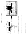
別の態様としては、反応槽は二次元配列のウェル、例えばマイクロタイタープレート、または図に示されているようなテープに沿ったスポットもしくはウェルである。これらの調整により複数試料および/または複数標的粒子の何れかの多重検出が可能となる。候補粒子および/または放出体細胞を自動送達するため、反応槽または標本収集器の何れかおよび放出体細胞貯蔵所が少なくとも二次元において指定可能である。アレイのウェルはまた、放出体細胞および候補粒子間の接触を容易にするための遠心管に対して、前述のような粘着および非粘着被覆で処理できる。 In another embodiment, the reaction vessel is a two-dimensional array of wells, such as a microtiter plate, or a spot or well along the tape as shown. These adjustments enable multiplex detection of either multiple samples and / or multiple target particles. To automatically deliver candidate particles and / or emitter cells, either a reaction vessel or specimen collector and emitter cell reservoir can be specified in at least two dimensions. The wells of the array can also be treated with adhesive and non-stick coatings as described above for centrifuge tubes to facilitate contact between the emitter cells and candidate particles.
標本収集器
試料を例えば、空気から収集するために異なる装置を使用できる。一般的には、空気サンプリング装置は液体(その中もしくは近くを空気もしくは気体が通過する)を含む、または空気もしくは気体がフィルタを通過する際に、粒子(例えば、標的粒子)を捕捉する多孔質フィルタを含む収集槽を有する。液体を含む収集槽に関しては、収集液体は遠心できるまたは別の方法でその液体から粒子を分離処理できる。分離した粒子を次いで、反応槽中に堆積させる。フィルタ(例えば、ニトロセルロース)を含む収集槽に関しては、フィルタまたはフィルタの一部は反応槽として作動できる。あるいは、粒子をフィルタから洗浄できる、またはフィルタを溶解できるもしくは別の方法で粒子を取り除くことができる。フィルタ収集槽はまた、そのフィルタ中を通って流れる液体(例えば、給水試料または脳脊椎液)から粒子を回収するために適応できる。さらに、上述のように、液体中に存在する任意の粒子物質を取り除くために液体試料を遠心できる。種々の試料採取装置(sampler)が周知であり、本発明に関する使用に適している。SKC BioSampler(登録商標)および他の試料採取装置を販売している、SKC, Inc.(www.skc.com)を参照されたい。
Different devices can be used to collect the sample collector sample from, for example, air. In general, an air sampling device contains a liquid (air or gas passes through or near it) or is porous to capture particles (e.g., target particles) as the air or gas passes through a filter. It has a collection tank containing a filter. For a collection tank containing a liquid, the collection liquid can be centrifuged or otherwise separated from the liquid. The separated particles are then deposited in the reaction vessel. For collection vessels that include a filter (eg, nitrocellulose), the filter or part of the filter can operate as a reaction vessel. Alternatively, the particles can be washed from the filter, or the filter can be dissolved or otherwise removed. The filter collection tank can also be adapted to collect particles from a fluid (eg, a water supply sample or cerebrospinal fluid) that flows through the filter. Furthermore, as described above, the liquid sample can be centrifuged to remove any particulate matter present in the liquid. Various samplers are well known and suitable for use with the present invention. See SKC, Inc. (www.skc.com), which sells SKC BioSampler® and other sampling devices.
その他の空気試料採取装置を使用できる。例えば、その代替装置はAir-O-Cellサンプリングカセット(SKC, Inc.)である。この装置では、浮遊微小粒子を加速させ、且つ種々の染色手順および顕微鏡検査にそのまま通用する粘着性スライドに衝突させる。 Other air sampling devices can be used. For example, the alternative device is an Air-O-Cell sampling cassette (SKC, Inc.). In this device, suspended microparticles are accelerated and collided with adhesive slides that can be used directly in various staining procedures and microscopy.
エアロゾル粒子は衝突捕集装置として知られる装置中の慣性分離を用いて回収してもよい。衝撃表面に向けられる場合、回収される粒子を含む空気流は関心のある環境から衝撃装置中に集められる。衝突捕集装置において適当な幾何学的パラメーターおよび流速を使うと、十分な慣性を有する粒子は流域をたどらず、表面上に衝突すると思われる。表面に衝突する粒子の大部分は、静電気および/またはファンデルワールス相互作用を介して付着し、それによって捕集されおよび濃縮される。このような方法で、本明細書の装置および方法を含む種々の利用可能なアッセイ方法を用いた検出を目的として、タンパク質(毒素を含む)、ウイルス、細菌(栄養型および胞子型)、寄生虫、花粉および他の検出可能な物質を含むエアロゾル粒子を捕集できる。 Aerosol particles may be recovered using inertial separation in an apparatus known as a collision collector. When directed to the impact surface, the air stream containing the recovered particles is collected into the impact device from the environment of interest. Using appropriate geometric parameters and flow velocities in the impact collector, it is likely that particles with sufficient inertia will not follow the watershed and will impinge on the surface. Most of the particles that impinge on the surface adhere via static electricity and / or van der Waals interactions and are thereby collected and concentrated. In this way, proteins (including toxins), viruses, bacteria (vegetative and spore types), parasites for the purpose of detection using a variety of available assay methods, including the devices and methods herein. Aerosol particles containing pollen and other detectable substances can be collected.
空気衝突捕集装置を用いた生物検定を目的とした乾式試料捕集により、流体消耗品および輸送機構を削減するおよび除去することで(これによりアッセイ費用が削減され、および自動化が平易になる)、従来の空気対液体試料捕集と比較して一般的な利点が提供される。本明細書の装置および方法に対する特別な利益のうち、乾式衝突捕集を用いた捕集により、個々の粒子検体のサイズに関わらず、本明細書の装置および方法のセンサー細胞の添加前に捕集された試料の全てがその表面上に設置されることが確実となる。これにより、液体中のそれらの沈降係数に関わらず全検体の局在化が達成され、その結果として本明細書の装置および方法の感度が最大化され、並びに時間のかかる段階を除去することによりアッセイ法の多数実施が促進される。 Dry sample collection for bioassays using air impact collection devices to reduce and eliminate fluid consumables and transport mechanisms (this reduces assay costs and simplifies automation) General advantages are provided compared to conventional air-to-liquid sample collection. Of particular benefit over the devices and methods herein, collection using dry impact collection allows the capture of sensor particles prior to addition of the sensor cells of the devices and methods herein, regardless of the size of individual particle analytes. It is ensured that all the collected samples are placed on the surface. This achieves localization of all analytes regardless of their sedimentation coefficient in the liquid, thereby maximizing the sensitivity of the devices and methods herein and eliminating time-consuming steps. Multiple implementations of the assay are facilitated.
表面上に衝突する粒子の大部分を保持するおよび引き続く生物検定に適合する任意の表面が、捕集表面として適している。適当な材料には、生体適合性金属、プラスチック、ガラス、結晶、エアロゲル、ヒドロゲル、紙などが含まれる。これらの材料の特に有用な構造形としては、微量遠心管、ハイスループットスクリーニングで使用されるマルチウェルプレート、連続テープ、フィルタ、側方流動免疫測定法(lateral flow immunoassays)の共役放出パッドなどが含まれる。捕集効率は、以下を含む捕集表面に対する改変により増大させることが可能である:生物学的粒子の接着を促進させる被覆剤(これらの被覆剤は本質的に化学薬品または生化学薬品とすることが可能である、例えば、ポリリジン)の添加、捕集可能な表面領域を増加させるための表面粗度の増大、および表面上の既定領域中に粒子の沈着を促進させる表面(幾何学的)構造の好ましい改変。さらに、さらなる捕集効率の改善は、捕集表面および入射粒子上の帯電をさらなる引力が生ずるように操作することにより達成できる。 Any surface that retains the majority of the impinging particles on the surface and is compatible with subsequent bioassays is suitable as a collection surface. Suitable materials include biocompatible metals, plastics, glass, crystals, aerogels, hydrogels, paper and the like. Particularly useful structural forms of these materials include microcentrifuge tubes, multi-well plates used in high-throughput screening, continuous tapes, filters, and conjugate release pads for lateral flow immunoassays. It is. Collection efficiency can be increased by modifications to the collection surface, including: coatings that promote the adhesion of biological particles (these coatings are essentially chemical or biochemical) Surface (for example, polylysine), increased surface roughness to increase the surface area that can be collected, and surfaces that promote particle deposition in a predetermined area on the surface (geometric) Preferred modification of the structure. Furthermore, further improvement in collection efficiency can be achieved by manipulating the charge on the collection surface and the incident particles so that more attractive forces are generated.
捕集表面上に衝突捕集される空気試料の各単位あたりの粒子数を増加させるために捕集器の上流に空気対空気型濃縮器を使用することにより、乾式衝突捕集器をさらに改善することができる。これにより、検出器に関して信頼性のある結果を提供するのに十分な数のエアロゾル粒子を捕集するための所要時間が著しく減少する。 Further improve the dry impact collector by using an air-to-air concentrator upstream of the collector to increase the number of particles per unit of air sample that is impacted and collected on the collection surface can do. This significantly reduces the time required to collect a sufficient number of aerosol particles to provide reliable results for the detector.
この捕集概念の一実施例として、エアロゾル試料を市販のプラスチックチューブの底に捕集するために図23に記載の衝突捕集装置を設定した。ノズルが管中の下方に突出しおよび出口が管内部表面の曲率半径に位置している。この位置付けにより、管の底で装置用センサー細胞(device sensor cells)が粒子と接触する可能性が最も高く、管の底における粒子衝突の可能性が増大する。捕集が完了したら直ちに、装置用センサー細胞を含有する1滴を、捕集したエアロゾル粒子を含有する管に直接添加し、管表面への細胞輸送を促進するため5秒間スピンし、および光子検出器(例えば、PMT、CCD、フォトダイオードなど)を用いて放出光を測定した。この装置を用いると、乾燥性の細菌胞子をエアロゾルから捕集でき、および光電子装置をにより、1分未満で直接同定できる。この方法は試料を捕集するために使用される複数の管および引き続いてアッセイを行う自動化システムにより実施できる。システムにより、少なくとも10個の独立したアッセイを行うことが可能となる方法の実施例が、図4、6、9、12、および15に示されている。1つの管で複数の被分析物を探索可能(多重化)とするようアッセイするアプローチを行うことにより、1回のアッセイサイクルで検出可能な物質数を利用可能な管の数よりも多くできる。これは、異なる被分析物に親和性のある複数の受容体を発現する個々の光電子検出装置用細胞株を作成するか、または異なる特異性を有する複数の細胞株を1つの管中で混合することにより、行うことができる。 As an example of this collection concept, a collision collection apparatus shown in FIG. 23 was set in order to collect an aerosol sample on the bottom of a commercially available plastic tube. The nozzle protrudes downward in the tube and the outlet is located at the radius of curvature of the inner surface of the tube. This positioning most likely causes device sensor cells to come into contact with the particles at the bottom of the tube, increasing the likelihood of particle collisions at the bottom of the tube. As soon as the collection is complete, add a drop containing instrument sensor cells directly to the tube containing the collected aerosol particles, spin for 5 seconds to facilitate cell transport to the tube surface, and photon detection The emitted light was measured using a vessel (eg, PMT, CCD, photodiode, etc.). With this device, dry bacterial spores can be collected from the aerosol and the optoelectronic device can be directly identified in less than a minute. This method can be performed with multiple tubes used to collect the sample and an automated system that subsequently performs the assay. Examples of methods by which the system allows at least 10 independent assays to be performed are shown in FIGS. 4, 6, 9, 12, and 15. By approaching multiple analytes to be searchable (multiplexed) in one tube, the number of substances that can be detected in a single assay cycle can be greater than the number of tubes available. This creates individual photo detector cell lines that express multiple receptors with affinity for different analytes, or mix multiple cell lines with different specificities in one tube This can be done.
図4は統合型バイオエアロゾル警告センサー(BAWS)/光電子センサーシステムの概略図である。BAWSトリガーモジュールは粒子の存在、例えば予め決定したサイズ範囲の粒子を予備的に検出するために使用される。基準を満たす粒子が検出されれば、BAWSは特定のサイズ範囲の粒子を回収し、乾式衝突捕集装置モジュールを介してウェル(例えば、反応槽、チューブ)中に堆積させることを可能とする空気対空気型濃縮器を始動させる。乾式衝突捕集装置モジュールは、乾燥試料の収集を可能とし、および反応槽(例えば、チューブ)中への細胞(例えば、放出細胞)送達を目的としたシリンジモジュールと連絡している。輸送モジュールは反応槽組立体(1つまたはそれ以上の試験槽またはチューブを有する)を、粒子試料および細胞の沈降または混合を目的とした遠心モジュールに輸送するために使用される。遠心モジュールは、必ずしも必要とされないが、光子放出の検出を目的とした光学/PMTモジュールと通信できる。制御モジュールはシステム操作の制御に有用である。 FIG. 4 is a schematic diagram of an integrated bioaerosol warning sensor (BAWS) / optoelectronic sensor system. The BAWS trigger module is used to preliminarily detect the presence of particles, for example particles of a predetermined size range. If particles that meet the criteria are detected, BAWS collects particles in a specific size range and allows air to be deposited in wells (e.g., reaction vessels, tubes) via a dry collision collector module. Start the air concentrator. The dry collision collector module is in communication with a syringe module that allows for the collection of dry samples and for delivery of cells (eg, release cells) into a reaction vessel (eg, a tube). The transport module is used to transport the reaction vessel assembly (with one or more test vessels or tubes) to a centrifuge module intended for sedimentation or mixing of particle samples and cells. A centrifuge module is not necessarily required, but can communicate with an optical / PMT module aimed at detecting photon emission. The control module is useful for controlling system operation.
図6は乾式衝突捕集装置モジュール概念の実施例を示している。本実施例において、空気対空気型濃縮器(これから粒子試験試料が収集される)と連絡した、個々の試料チューブ(例えばPCRチューブ)およびチューブ担体を含め、シングルチャネル検出器(例えば、原型システム)の他にマルチチャネル検出器が図解されている。 FIG. 6 shows an example of the concept of the dry collision collector module. In this example, a single channel detector (e.g., a prototype system), including individual sample tubes (e.g., PCR tubes) and a tube carrier in communication with an air-to-air concentrator (from which particle test samples are collected). In addition, a multi-channel detector is illustrated.
図9は自動化可能な細胞輸送の実施例を示している。センサー細胞(例えば、放出細胞)は、シリンジおよびシリンジポンプの配置(ピペッターまたは他の輸送器具を含むことができる)によりシステムに導入される。この種の組立体により、粒子試料(例えば、反応槽(例えば、チューブ)中の試料)へのセンサー細胞の複数および同時導入が可能となる。 FIG. 9 shows an example of cell transport that can be automated. Sensor cells (eg, release cells) are introduced into the system via a syringe and syringe pump arrangement (which can include a pipetter or other transport device). This type of assembly allows multiple and simultaneous introduction of sensor cells into a particle sample (eg, a sample in a reaction vessel (eg, a tube)).
図12は粒子試料または細胞試料をスピンするために使用される遠心モジュール概念の実施例を示している。試料チューブを有する担体は、担体を受けるのに適したローター組立体中に、装填構造により導入される。ローターにより試料がスピンされる。ローター組立体はシグナル収集(例えば、光子放出)を目的とした光学モジュールと連絡しており、インデックスモータは、試料槽を検出器(例えば、光学モジュール)と並置させるために使用できる。 FIG. 12 shows an example of a centrifugal module concept used to spin particle or cell samples. A carrier having a sample tube is introduced by a loading structure into a rotor assembly suitable for receiving the carrier. The sample is spun by the rotor. The rotor assembly is in communication with an optical module intended for signal collection (eg, photon emission) and an index motor can be used to juxtapose the sample reservoir with the detector (eg, optical module).
図15は光学モジュールの実施例を示している。正確な遠心によって、そのモジュールにより複数の試料の同時試験(例えば、反応槽、チューブ中)が可能となる。担体およびその中のチューブはそれらがレンズ組立体(例えば、統合型反射体、レンズ)、必要ならば光検出器(例えば、PMT)と連絡するようにそのユニットに導入される。PMTにより処理用プロセッサおよび表示部に送られるシグナルが生じる。 FIG. 15 shows an embodiment of the optical module. With accurate centrifugation, the module allows simultaneous testing of multiple samples (eg, in a reaction vessel, tube). The carrier and the tubes therein are introduced into the unit so that they communicate with the lens assembly (eg, integrated reflector, lens) and, if necessary, the photodetector (eg, PMT). The PMT generates a signal that is sent to the processing processor and display.
図21は統合型乾式衝突捕集装置/光電子センサーを図解している。このセンサーにおいて、上述のモジュールはベルト駆動式担体輸送モジュールへ輸送可能な30個の担体を保持するカセットと直線配置で組み立てられる。この輸送モジュールはアッセイチューブを収集器から細胞輸送モジュールへ、遠心モジュールへ、および最終的には光子検出の完了後に確認用試料貯蔵モジュールへ順番に移動させる。この統合型センサーの全体の大きさは、およそ幅54インチ×高さ33インチ×奥行き22インチである。 Figure 21 illustrates an integrated dry collision collector / photoelectronic sensor. In this sensor, the module described above is assembled in a linear arrangement with a cassette holding 30 carriers that can be transported to a belt-driven carrier transport module. This transport module sequentially moves the assay tube from the collector to the cell transport module, to the centrifuge module, and finally to the confirming sample storage module after completion of photon detection. The overall size of this integrated sensor is approximately 54 inches wide x 33 inches high x 22 inches deep.
現実世界の試料には、アッセイを阻害するか(偽陰性)または特異抗原がないのに反応を起こすか(偽陽性)のどちらかの物質が含まれうる。多くの場合、試料はアッセイの前に処理し、これらの物質を取り除くことができる。例えば、界面活性剤または血清因子のような可溶性物質は、事前の遠心段階により取り除くことができ、ここで作用因子はチューブの底に濃縮され、それからその液体をアッセイ培地に置換する(関門防護(Portal Shield)試料)。不溶性で、大きな粒子状物質は、作用因子は通過させるが、汚染物質(ディーゼルまたは煤煙試料)を保持する孔径(3〜5μm)の市販のフィルタを用い、ろ過により試料から取り除くことができる。試料はシリンジフィルタを通して直ちに処理することができ、全体のアッセイ時間に僅か数分が加算されるだけである。 Real-world samples can contain substances that either inhibit the assay (false negative) or react in the absence of a specific antigen (false positive). In many cases, the sample can be processed prior to the assay to remove these materials. For example, soluble substances such as detergents or serum factors can be removed by a pre-centrifugation step, where the agent is concentrated at the bottom of the tube and then the liquid is replaced with assay media (barrier protection ( Portal Shield) sample). Insoluble, large particulate matter can be removed from the sample by filtration using a commercially available filter with a pore size (3-5 μm) that retains the contaminants (diesel or soot sample) while allowing the agent to pass through. The sample can be processed immediately through the syringe filter, adding only a few minutes to the total assay time.
標本局在化
標本収集器または反応槽の一部として、放出体細胞および候補粒子間の接触を容易にするために別の機構(遠心以外の)を導入できる。例えば、生体電子工学装置における電気泳動、等電点電気泳動、誘導泳動、磁気標識粒子などの利用は、本発明のシステムに組み入れられる。例えば、米国特許第6,017,696号およびナノジェン(Nanogen, Inc)社(www.nanogen.com)に譲渡された他の特許;Goaterら、Parasitology 117:S177-189, 1998; 並びに米国特許第5,512,439号および第4,910,148号およびDynal AS(www.dynal.no)に譲渡された他の特許を参照されたい。
As part of the specimen localization specimen collector or reaction vessel, another mechanism (other than centrifugation) can be introduced to facilitate contact between the emitter cells and the candidate particles. For example, the use of electrophoresis, isoelectric focusing, induction electrophoresis, magnetically labeled particles, etc. in a bioelectronic device is incorporated into the system of the present invention. For example, U.S. Patent No. 6,017,696 and other patents assigned to Nanogen, Inc. (www.nanogen.com); Goater et al., Parasitology 117: S177-189, 1998; and U.S. Patent Nos. 5,512,439 and See 4,910,148 and other patents assigned to Dynal AS ( www.dynal.no ).
標的粒子(ここで粒子は放出体細胞-光子/毒素、ウイルス、細菌、寄生虫、核酸などにより識別されるあらゆるものとすることが可能である)を含む水性試料を、放出体細胞を含む培地の一部と混合することにより、光子放出速度の一過性の増加をもたらす粒子-細胞接触が結果として引き起こされる。混合過程の開始と最大放出速度との間の時間は、混合が起こるまでの時間(混合時間)並びに粒子および細胞が混合後に接触するための典型的な時間(拡散時間)の他に、刺激に対する特定の細胞の応答特性に依存する。 An aqueous sample containing target particles (where the particles can be anything identified by emitter cells-photons / toxins, viruses, bacteria, parasites, nucleic acids, etc.), medium containing emitter cells Mixing with a portion of the resulting particle-cell contact results in a transient increase in the photon emission rate. In addition to the time until mixing occurs (mixing time) and the typical time for particles and cells to contact after mixing (diffusion time), the time between the start of the mixing process and the maximum release rate is Depends on specific cell response characteristics.
検出された光子のバックグラウンドの割合は標的粒子が存在しない状態でもなお存在する(例えば、細胞放出および光子検出器およびその電子機器中の温度ノイズによるバックグラウンド)ので、たった一つの標的-細胞相互作用から放出される光子をこのバックグラウンドと識別することは困難となりうる。シグナルとして有用であるためには、バックグラウンドの割合を超える検出光子の割合の著しい増加が必要である。任意の試料に対して、混合時間および拡散時間が最小化される場合、この割合は最大化される。標的粒子が試料中に存在する可能性のある他のシグナルには以下が含まれる:バックグラウンド単独のその総数を超える一定の期間に検出される光子の総数の増加、検出される光子の統計的変化、または検出される光子のスペクトル性質の変化。 Since the percentage of detected photon background is still present in the absence of target particles (e.g. cell emission and background due to temperature noise in the photon detector and its electronics), only one target-cell interaction It can be difficult to distinguish photons emitted from the action from this background. In order to be useful as a signal, a significant increase in the proportion of detected photons over the proportion of background is required. For any sample, this ratio is maximized if the mixing and diffusion times are minimized. Other signals that the target particles may be present in the sample include: increase in the total number of photons detected over a period of time that exceeds the total number of background alone, statistical of the detected photons Change or change in the spectral properties of the detected photons.
混合後の粒子および細胞間の平均距離を減少させることにより、拡散時間を最小化できる。これは、粒子および/または細胞を大きな混合容積内のより小さな容積内、たいてい一層に局在化させることにより達成されうる。しかし、粒子および/または細胞を局在化させる時間は、その細胞に特異的な応答時間よりも長くなる可能性がある(この長時間の局在化に渡る粒子および細胞間の混合によっては、放出までの平均時間が増加することにより、光子放出の割合がより低下する、および従って、シグナルがより低下する可能性が有る)。これを回避するために、片方または両方を分けて局在化させるべきであり、これにより一方では両者間の接触が最小化される。この局在化はまた、混合時間の減少に繋がる。 By reducing the average distance between particles and cells after mixing, the diffusion time can be minimized. This can be achieved by localizing the particles and / or cells in a smaller volume within a large mixing volume, mostly more. However, the time to localize the particles and / or cells can be longer than the response time specific to that cell (depending on the mixing between particles and cells over this long localization, Increasing the average time to emission reduces the rate of photon emission, and thus may reduce the signal). To avoid this, one or both should be localized and this minimizes contact between them. This localization also leads to a reduction in mixing time.
一般的に、粒子または細胞を移動させる方法には以下が含まれる:
・沈降法(重力または遠心により)
・流体流れによる方法(強制流または対流)
・電気力による方法(電気泳動および誘導泳動)
・磁力による方法(磁気ビーズを用いて)
・音響/超音波法(砂波形または伝搬波形)
In general, methods for moving particles or cells include:
・ Sedimentation method (by gravity or centrifugation)
・ Method based on fluid flow (forced flow or convection)
・ Method by electric force (electrophoresis and induction)
・ Method using magnetic force (using magnetic beads)
・ Acoustic / ultrasonic method (sand waveform or propagation waveform)
局在化にはチャネルもしくは容器の固体表面、フィルタ表面、または最小電界を取り囲む位置エネルギー障壁のような、粒子および/または細胞を捕集できる障壁と合わせて粒子および/または細胞を移動させる方法が必要となる。実施例としては以下が含まれる:
・沈降法(試験槽のより低い面への細胞の局在化)
・空気衝突捕集法(衝突粒子の捕集表面への接着または定着)
・フィルタリング法(粒子または細胞のフィルタ表面へのまたはその本体中での捕集)
・アフィニティー捕獲法(粒子または細胞は特異的または非特異的結合による相互作用を介して局在化できる)
・磁気捕獲法(固体表面、フィルタ表面、または局在化磁力によるフィルタ本体中に保持された磁気ビーズ、;ビーズは粒子または細胞の付着を促進する化学的表面を持っていても持っていなくてもよい)
・電気泳動法(荷電粒子のみ;電極表面への捕集)
・誘導泳動法(正:電極表面への粒子または細胞の捕集;負:最小電界領域内への捕集)
Localization involves moving particles and / or cells with a solid surface of a channel or container, a filter surface, or a barrier that can trap particles and / or cells, such as a potential energy barrier that surrounds a minimum electric field. Necessary. Examples include the following:
Sedimentation method (localization of cells to the lower surface of the test chamber)
・ Air collision collection method (adhesion or fixation of collision particles to the collection surface)
Filtering method (collection of particles or cells on the filter surface or in its body)
Affinity capture method (particles or cells can be localized through specific or non-specific binding interactions)
Magnetic capture method (solid surface, filter surface, or magnetic beads held in the filter body by a localized magnetic force; the beads may or may not have chemical surfaces that promote particle or cell attachment (May be)
・ Electrophoresis (charged particles only; collection on the electrode surface)
Induction electrophoresis (positive: collection of particles or cells on the electrode surface; negative: collection in the minimum electric field region)
粒子および細胞の局在化および混合は、上記の方法だけでなく、他の方法を組合せることにより達成できる。以下の表に、種々の局在化/検出器の組合せの実施例を示す。示した実施例のいくつかは、粒子または細胞を二次元的に局在化させる方法を例示しており、単一光子検出器(例えばPMT)に対して光子検出器アレイ(CCDを含む)を使用した場合、異なる粒子間の感度または識別が改善される。 Particle and cell localization and mixing can be achieved by combining not only the above methods, but also other methods. The following table shows examples of various localization / detector combinations. Some of the examples shown illustrate methods for localizing particles or cells two-dimensionally, with a photon detector array (including CCD) versus a single photon detector (e.g. PMT). When used, sensitivity or discrimination between different particles is improved.

局在化実施例
以下の実施例のそれぞれにおいて、特に記述がない場合は以下のとおりに想定される:試料は標的粒子を含む可能性のある(以下の記述は粒子が存在することを想定しているが)、短期の細胞寿命および機能に適合した水溶液の一部である。水性試料は環境試料、臨床試料、空気対液体試料、拭き取り洗浄(washed-swab)試料、またはその他の試料から得られる。空気試料は圧縮空気流(空気試料採取装置または表面捕集)、静電気捕獲、または定着した浮遊微小粒子から得られる。細胞への言及は、それらの寿命および機能と適合した水性培地中の放出体細胞を意味するものと理解されるべきである。接触した粒子および細胞により、結果として1つまたはそれ以上の光子放出が引き起こされると想定される。単一またはアレイ型の光子検出器は試料および細胞が混合される試験槽の外部に存在し、並びに試験槽の外部または内部のどちらかに、放出された光子の捕獲および検出を促進する光学部品(例えば、鏡、レンズ、道光板など)が追加されてもよい。試験槽は一部もしくは全体が透明であるかまたは放出された光子を検出器に到達させる別の方法を有するかのどちらかであると想定される。
Localization Examples In each of the following examples, unless otherwise stated, the sample is assumed as follows: The sample may contain target particles (the following description assumes that particles are present) However, it is part of an aqueous solution adapted for short cell life and function. Aqueous samples are obtained from environmental samples, clinical samples, air-to-liquid samples, washed-swab samples, or other samples. The air sample is obtained from a compressed air stream (air sampler or surface collection), electrostatic capture, or settled airborne microparticles. Reference to cells should be understood to mean emitter cells in aqueous medium that are compatible with their lifetime and function. It is assumed that the contacted particles and cells result in one or more photon emissions. Single or array photon detectors are external to the test chamber where the sample and cells are mixed, and optical components that facilitate capture and detection of emitted photons either outside or inside the test chamber (For example, a mirror, a lens, a light guide plate, etc.) may be added. It is envisaged that the test chamber is either partially or wholly transparent or has another way of causing the emitted photons to reach the detector.
遠心
試料は粒子を沈降させるのに十分な時間、試験槽中で遠心されうる。細胞は粒子をかき乱さないように試験槽に導入されおよびそれらの細胞をその粒子上に沈降させるため簡単に遠心されうる。スピンの間、またはより典型的にはスピン後に、光子を検出できる。
The centrifuged sample can be centrifuged in the test chamber for a time sufficient to allow the particles to settle. The cells can be introduced into the test chamber so as not to disturb the particles and simply centrifuged to allow the cells to settle onto the particles. Photons can be detected during spin, or more typically after spin.
アフィニティー捕獲(表面捕獲)
試料は微量遠心管、マルチウェルプレート、フィルタユニット、または特異もしくは非特異結合による相互作用を介して試料中に存在している可能性のある粒子を結合および保持できるように、試料と接触するその表面の一部が改変されている他の適当な器具中に導入されうる。非特異結合は静電気/イオン交換相互作用、疎水性相互作用、親水性相互作用などを介して促進されうる。特異結合は前記表面に粒子上の基質に結合する成分(例えば、抗体、受容体、糖タンパク質、タンパク質、ペプチド、糖質、オリゴヌクレオチドなど)を固定化することにより、または粒子表面上の受容体により結合される成分(低分子、ペプチド、タンパク質、糖質など)を固定化することにより促進されうる。
Affinity capture (surface capture)
The sample is in contact with the sample so that it can bind and retain particles that may be present in the sample via microcentrifuge tubes, multi-well plates, filter units, or specific or non-specific binding interactions. It can be introduced into other suitable devices in which part of the surface has been modified. Non-specific binding can be promoted through electrostatic / ion exchange interactions, hydrophobic interactions, hydrophilic interactions, and the like. Specific binding is achieved by immobilizing a component (eg, antibody, receptor, glycoprotein, protein, peptide, carbohydrate, oligonucleotide, etc.) that binds to the substrate on the surface, or a receptor on the particle surface. Can be facilitated by immobilizing components (small molecules, peptides, proteins, carbohydrates, etc.) bound by
アフィニティー捕獲(動的基質への)
表面上へのアフィニティー捕獲と同様であるが、粒子は本明細書に記載される方法を含めた種々の方法により、粒子または細胞を移動させるおよび/または局在化させるさらなる手段を提供する動的基質(ポリマービーズ、細胞、荷電分子、磁気ビーズ、細菌など)に結合する。
Affinity capture (to dynamic substrate)
Dynamics that are similar to affinity capture on surfaces, but that provide additional means to move and / or localize particles or cells by various methods, including those described herein. Bind to substrates (polymer beads, cells, charged molecules, magnetic beads, bacteria, etc.).
フローセル
放出体細胞を浅いフローセル(shallow flow cell)に導入しおよびその底面に付着できる;非接着性細胞はさらなるフローにより除去できる。試料を導入し、多量の細胞培地を移動させることで、粒子を前記付着細胞上に沈降できる。粒子が細胞と接触する時に、光子が放出される。
Flow cell emitter cells can be introduced into and attached to the shallow flow cell; non-adherent cells can be removed by further flow. By introducing a sample and moving a large amount of cell culture medium, particles can be settled on the adherent cells. Photons are emitted when the particles come into contact with the cells.
フローセル(複数細胞ライン)
フローセルと同様であり、種々の標的粒子に対して高感度な放出体細胞からなる別領域を備えている。細胞が刺激され、および従って、標的粒子が試料中に存在していることの同定を可能とする画像検出器による光子検出である。
Flow cell (multi-cell line)
Similar to a flow cell, it has a separate region of emitter cells sensitive to various target particles. Photon detection with an image detector that allows the cells to be stimulated and thus to identify that the target particles are present in the sample.
フローセル(磁気ビーズ)
フローセルと同様。適当な磁気ビーズを試料と混合し、標的粒子をビーズと付着させる。これらの粒子付着ビーズ(decorated beads)をフローセルに導入可能であり、そこで強力な局所磁界(永久磁石または電磁石により)によりビーズはその付着細胞上方の表面に捕獲される。磁力を取り除いてビーズをその細胞上に沈降させるか、またはビーズを細胞が付着した表面へ引き寄せるように磁力を移動させるかのどちらかにより、混合を開始できる。
Flow cell (magnetic beads)
Same as flow cell. Appropriate magnetic beads are mixed with the sample and target particles are attached to the beads. These decorated beads can be introduced into the flow cell where the beads are captured on the surface above the attached cells by a strong local magnetic field (by a permanent magnet or electromagnet). Mixing can be initiated by either removing the magnetic force and allowing the beads to settle onto the cells, or by moving the magnetic force to attract the beads to the surface to which the cells are attached.
フローセル(電界)
フローセルと同様であり、細胞が付着する表面を備えおよびその平行表面が分離電極である(少なくともそれらのうち一面は透明とする)。多量の細胞培地を置換して、細胞を導入できる。適当な直流電圧を電極間に加えると、粒子は電気泳動により付着細胞の方へ移動する。
Flow cell (electric field)
Similar to a flow cell, it has a surface to which cells adhere and its parallel surface is a separation electrode (at least one of them is transparent). A large amount of cell culture medium can be replaced to introduce cells. When an appropriate DC voltage is applied between the electrodes, the particles move towards the adherent cells by electrophoresis.
テープ/ウィック
標的粒子を含む可能性のある空気試料は、柔軟性なしまたは柔軟性(例えば、テープ)、多孔性または非多孔性とすることが可能である、透明な表面上へ衝突捕集できる。吸収素材、またはウィックを衝突領域周辺または、多孔性表面の場合には、その表面の反対側に付着できる。細胞を衝突領域に入れることができ、そして、ウィックにより、過剰な培地は吸収され、細胞を含む培地の容積および深さが減少し且つ細胞は粒子にさらに接近すると思われる。表面が、背面にウィック素材を備えた多孔質である場合、細胞は衝突捕集した粒子上に沈降するまたはさらに、フローによりそれらの方へ引き寄せられる。
Air samples that may contain tape / wick target particles can be impinged on a transparent surface that can be non-flexible or flexible (e.g., tape), porous or non-porous . An absorbent material, or wick, can be attached around the impact area or, in the case of a porous surface, on the opposite side of the surface. The cells can enter the collision area and the wick appears to absorb excess media, reduce the volume and depth of the media containing the cells, and bring the cells closer to the particles. If the surface is porous with a wick material on the back, the cells settle on the impacted particles or are further drawn towards them by flow.
空気衝突捕集
標的粒子を含む可能性のある空気試料は、遠心に適した(固定されたおよび最初は空の)試験槽中に衝突捕集できる。粒子をかき乱さないように細胞を試験槽に導入し且つ細胞を粒子上に沈殿させるために短時間、遠心する。スピンなし、スピンの間、または、より典型的には、スピン後に、光子を検出できる。
Air samples that may contain air impact collection target particles can be impact collected in a test chamber suitable for centrifugation (fixed and initially empty). The cells are introduced into the test tank so as not to disturb the particles and centrifuged briefly for the cells to settle on the particles. Photons can be detected without spin, during spin, or more typically after spin.
フィルタ器具/磁気ビーズ
試験槽および適当なフィルタを備えたプランジャからなる改良シリンジレスフィルタ器具(Whatman(登録商標) Mini-Uniprep(商標)、または類似品)に、試験槽の底面に付着させる細胞を充填できる;非付着細胞は洗い流すことができる。試験槽に適当な表面親和力を持った磁気ビーズとともに試料を導入できる。閉じ込められた空気をフィルタから逃がすまで、試験槽中へ適切な磁石がフィルタの後部側内部に挿入されおよびその近傍に固定された改良プランジャを挿入できる。この組立体は逆さにでき、且つ(ビーズがフィルタ表面上に沈降する時間の経過後に可能であるが)試験槽をプランジャ上へ押し下げることができる。ろ過、沈降、および磁力により磁気ビーズおよび粒子をフィルタ表面に蓄積できる。粒子は磁気ビーズに付着しても、またはそれらの間に捕らえられてもよい。組立体を再び逆さにした直後、粒子は磁気ビーズにより細胞から遠ざけられ、その磁気ビーズは、プランジャ内部の磁石により拘束されている。その磁石を取り除くことにより、ビーズが解放され、そして粒子はその短距離を横断して細胞上に沈降する。
A modified syringe-less filter instrument (Whatman® Mini-UniprepTM, or similar) consisting of a filter instrument / magnetic bead test tank and a plunger with an appropriate filter, allows cells to adhere to the bottom of the test tank. Can be filled; non-adherent cells can be washed away. The sample can be introduced into the test tank together with magnetic beads having an appropriate surface affinity. Until the trapped air escapes from the filter, a suitable magnet can be inserted into the interior of the rear side of the filter into the test chamber and a modified plunger secured in the vicinity thereof. This assembly can be inverted and the test chamber can be pushed down onto the plunger (although it is possible after the time that the beads settle on the filter surface). Magnetic beads and particles can accumulate on the filter surface by filtration, sedimentation, and magnetic force. The particles may be attached to the magnetic beads or trapped between them. Immediately after the assembly is inverted again, the particles are moved away from the cells by magnetic beads, which are constrained by a magnet inside the plunger. By removing the magnet, the beads are released and the particles settle on the cells across the short distance.
フローパストセル
1つまたはそれ以上の細胞槽を試験槽底面の適当なフィルタまたは膜上に沈降させることが可能となる。試料を細胞上方の試験槽に導入でき且つ圧力を加えることができる(例えば、プランジャまたは外部ポンプにより)。試料は、緊密な接触状態にある細胞を通過して流れるので、粒子は細胞の近距離内に近付けられ、接触が可能となる。
Flow past cell
One or more cell reservoirs can be allowed to settle on a suitable filter or membrane at the bottom of the test chamber. The sample can be introduced into the test chamber above the cells and pressure can be applied (eg, by a plunger or an external pump). As the sample flows through the cells in close contact, the particles are brought into close proximity of the cells and contact is possible.
カウンターフロー
1つまたはそれ以上の細胞槽を「細胞」試験槽底面の適当なフィルタまたは膜上に沈降させることが可能となる。試料は、幾つかのフローチャネルにより、フィルタ下部で細胞試験槽と接続している別の「試料」試験槽に入れられる。試験槽は互いに遠心において、試料試験槽が回転軸により接近するような相対配置とすることができる;試料試験槽中の液体面は細胞試験槽中の液体よりも回転軸により接近する。この方法により、遠心回転の間、液体は試験槽間を回転軸からの距離が同じになるように流れると思われる。これにより、細胞を支えているフィルタを通して、および外側に向う遠心力によるその流れに抵抗している細胞のそばを通して試料の一部を上昇させうる。試料は、緊密な接触状態にある細胞を通過して流れるので、粒子は細胞の近距離内に近付けられ、接触が可能となる。
Counter flow
One or more cell reservoirs can be sedimented onto a suitable filter or membrane at the bottom of the “cell” test chamber. The sample is placed by a number of flow channels into a separate “sample” test tank connected to the cell test tank below the filter. The test chambers can be positioned relative to each other so that the sample test chambers are closer to the axis of rotation in a centrifuge; the liquid surface in the sample test chamber is closer to the axis of rotation than the liquid in the cell test chamber. With this method, during centrifugal rotation, liquid appears to flow between test chambers at the same distance from the axis of rotation. This can cause a portion of the sample to rise through the filter supporting the cell and beside the cell resisting that flow due to outward centrifugal forces. As the sample flows through the cells in close contact, the particles are brought into close proximity of the cells and contact is possible.
遠心管フィルタ
試料を適当な分画サイズを有する遠心管フィルタのフィルタかごに導入する。適当な遠心条件の下で、フィルタに試料を通過させ、フィルタの分画サイズよりも大きな粒子をフィルタ表面上に蓄積させる。細胞をフィルタかごに導入しおよびフィルタ表面および粒子上に細胞を持って行くために短時間、遠心する。
The centrifuge tube sample is introduced into the filter cage of the centrifuge tube filter having the appropriate fraction size. Under appropriate centrifugation conditions, the sample is passed through the filter, causing particles larger than the filter fraction size to accumulate on the filter surface. Introduce the cells into the filter basket and centrifuge briefly to bring the cells over the filter surface and particles.
誘導泳動トラップ
フローセルと同様であるが、適当な電極が表面上の一部に備えられているかまたはフローセル中に突き出している。試料は外部電源に接続されおよび電気的に駆動されうる並びに外部電源になりうる、電極近くを通る連続フローにより導入できる。流速、周波数、波形、および振幅の適当な組合せに対し、粒子は負の誘導泳動により細胞上方の最小電界強度の領域に導かれて捕捉される。フローの停止および電気的駆動力を電極(恐らく電気泳動力を生ずるいくつかの電極間の直流電圧が含まれる)に変更後、粒子を沈降できるまたは付着細胞上に移動できる(電気泳動または正の誘導泳動により)。
Similar to an electrophoretic trap flow cell, but with a suitable electrode provided on a portion of the surface or protruding into the flow cell. The sample can be introduced by a continuous flow through the electrodes, which can be connected to an external power source and electrically driven as well as can be an external power source. For an appropriate combination of flow velocity, frequency, waveform, and amplitude, the particles are directed and captured in the region of minimal electric field strength above the cell by negative induction. After changing the flow cessation and electrical driving force to electrodes (possibly including a DC voltage between several electrodes that produce electrophoretic forces), the particles can settle or migrate onto adherent cells (electrophoresis or positive) By induction electrophoresis).
伝搬波形誘導泳動
偏平な円筒試験槽において、粒子を捕捉するための中央平面電極、その周辺を囲む電極、および一組の螺旋電極(中央電極と同じ側の表面あるいはその反対側の表面のどちらか)を含め、適当な電極(恐らく、透明の)を平行面の片側または両側に組み立てることができる。試料は試験槽に導入され、および電気泳動により粒子を中央電極に引きつけるため、周辺および中央電極間に直流電位が印加される。流体の交換により、細胞を試験槽に導入できる。適当な位相シフト方式交流電圧を備えた螺旋電極に電圧を加えると、伝搬波形誘導泳動により細胞を中央部に押しやることができ、そしてそこで細胞を粒子上に沈降できる。
Propagation waveform guided electrophoresis In a flat cylindrical test chamber, a central planar electrode for capturing particles, an electrode surrounding it, and a set of helical electrodes (either the surface on the same side as the central electrode or the opposite surface) Suitable electrodes (possibly transparent) can be assembled on one or both sides of the parallel plane. A sample is introduced into the test chamber, and a DC potential is applied between the peripheral and central electrodes to attract the particles to the central electrode by electrophoresis. Cells can be introduced into the test chamber by fluid exchange. When a voltage is applied to a helical electrode with an appropriate phase shift alternating voltage, the cell can be pushed to the center by propagating wave-guided electrophoresis, where it can settle onto the particle.
溶解膜チューブ
遠心沈降による粒子の局在化の間に、標的粒子および放出体細胞間の分離を維持するために、電気作動の溶解性金膜(electrically-actuated dissolvable gold membrane)を利用できる。粒子が細胞真上の膜上に沈降されるか(図20に示されるように)、または細胞が膜貫通により試験槽底面から別の試験槽(恐らく、挿入物)底面に遠ざけられるかのどちらかである。どちらの場合も、電気的活性化により膜を溶解後、粒子および細胞を、沈降あるいは遠心により混合する。
An electrically actuated dissolvable gold membrane can be utilized to maintain separation between target particles and emitter cells during particle localization by lysis membrane tube centrifugation. Either the particles settle on the membrane directly above the cell (as shown in Figure 20) or the cell is moved from the bottom of the test chamber to the bottom of another test chamber (possibly an insert) by transmembrane. It is. In either case, after lysing the membrane by electrical activation, the particles and cells are mixed by sedimentation or centrifugation.
音響/超音波
粒子の濃縮は音響または超音波シグナルを用いて達成されてもよい。粒子は砂波形中の波節に蓄積されうるか、または伝搬波形により移動されうる。細胞は同様にして、このように移動されうるか、または上述のいくつかの手段のいずれかにより輸送されうる。
Concentration of acoustic / ultrasonic particles may be achieved using acoustic or ultrasonic signals. The particles can accumulate in the wave nodes in the sand waveform or can be moved by the propagation waveform. Cells can likewise be moved in this way or transported by any of the several means described above.
毒素検出
一価抗原を検出するために、2つの一般的な戦略のうちの1つを用いて表面抗体の架橋を誘発することが必要である。第1に、一方は2つの受容体分子が単一リガンドに結合できるように、2つの独立した結合部位をその細胞表面上に発現する。あるいは、リガンドが多価であるかのような形で細胞に提示される場合、1つの結合部位をその細胞表面上に発現できる。以下は抗体-抗原認識モデルを用いた具体的実施例である。
To detect toxin detection monovalent antigens, it is necessary to induce cross-linking of surface antibodies using one of two general strategies. First, one expresses two independent binding sites on its cell surface so that two receptor molecules can bind to a single ligand. Alternatively, a binding site can be expressed on the cell surface when the ligand is presented to the cell as if it were multivalent. The following are specific examples using an antibody-antigen recognition model.
第1に、それぞれ個々の分子の異なる抗原決定基(抗原決定基1および2)に特異的な、2つの抗体を単一細胞株のその表面上に発現できる。単一分子の2つの抗体(一方は抗原決定基1に対する抗体および他方は抗原決定基2に対する抗体)との結合により、架橋および光の放出が開始されると思われる。より具体的には、それぞれが単一分子上の異なる抗原決定基を認識する、2つの独立した抗体を発現するように単一B細胞株を遺伝子工学で作り変える。単量体抗原(monomeric antigen)の存在により、もはやその表面抗体を架橋可能であり、結果的に細胞内Ca2+の増加およびエクオリンによる光の放出が引き起こされる。本発明者らは現在、ペスト菌(Y. pestis)および野兎病菌(F. tularensis)の両方に対する機能性抗体(内在的に発現されたPC抗体に加えて)を発現する細胞株を有している。これらの因子(病因)のそれぞれがこの細胞株により独立的に認識されることから、両抗体とも機能的であることを示唆しており、およびB細胞は2つの機能性抗体を同時に発現できることを実証している。
First, two antibodies, specific for different antigenic determinants (
別の潜在的な問題は、遠心力を用いて沈殿できない抗原に関する光電子装置および方法の感度である。ペスト菌F1抗原は溶液中に低分子量ポリマーとして存在する、および従って、本発明者らのアッセイ法においては沈降できない。しかし、F1に対する抗体を発現しているB細胞は可溶性F1抗原を5ng/mlで検出できる。これは現在の免疫測定法と比べて遜色がなくおよび光電子装置は可溶性因子に対してかなり高感度とすることが可能であることを実証している。卵白アルブミンに結合したホスホリルコリン抗原を用いて相補実験を行った。この小さな抗原の細胞表面上での抗体架橋の刺激能から、PC抗原決定基の複数コピーを含むこの低分子量抗原は、表面抗体を効果的に架橋でき、並びにカルシウム流入および光子放出を生み出すことができることが示唆される。 Another potential problem is the sensitivity of optoelectronic devices and methods for antigens that cannot be precipitated using centrifugal force. The Plasmodium F1 antigen exists as a low molecular weight polymer in solution and therefore cannot be precipitated in our assay. However, B cells expressing antibodies against F1 can detect soluble F1 antigen at 5 ng / ml. This demonstrates that it is inferior to current immunoassays and that optoelectronic devices can be quite sensitive to soluble factors. Complementation experiments were performed using phosphorylcholine antigen bound to ovalbumin. Due to the ability of this small antigen to stimulate antibody cross-linking on the cell surface, this low molecular weight antigen containing multiple copies of PC antigenic determinants can effectively cross-link surface antibodies and produce calcium influx and photon release. It is suggested that it can be done.
第2の戦略は遠心形式を利用することにより前掲の一価抗原の検出限界を改善できる。この取り組み方法では毒素抗体のうちの1つを良性細菌の表面上に発現させおよび第2の抗体をB細胞の表面に発現させるという基本構想を利用している。もはや毒素は遠心により沈降できる、および第2の抗体を発現しているB細胞を添加できる。複数抗原が細菌表面上に固定されるので、毒素は本質的にB細胞に対して多価であると思われ、そして架橋事象および光子放出が開始される。より具体的には、一価抗原(例えば、毒素)の抗原決定基1に対する抗体を細菌表面に発現させる。可溶性毒素はそれらの抗体に結合し、細菌を毒素抗原で被覆する。抗原決定基2に対する抗体を発現しているB細胞を添加する前に、これらの毒素被覆細菌を遠心により沈降する。B細胞抗体の架橋により、結果としてエクオリンによる光放出が引き起こされる。この戦略に関する実験結果から、細菌表面抗原の検出の実行可能性、およびB細胞の添加前にそれらの細菌を沈降することから生ずる感度増加が実証される。任意の沈降不完全な因子に関してB細胞に対するその提示を改善するため、同様の取り組み方法をまた、利用できる。
The second strategy can improve the detection limit of the monovalent antigen described above by using a centrifugal format. This approach utilizes the basic concept of expressing one of the toxin antibodies on the surface of a benign bacterium and a second antibody on the surface of a B cell. The toxin can no longer be sedimented by centrifugation, and B cells expressing the second antibody can be added. As multiple antigens are immobilized on the bacterial surface, the toxin appears to be essentially multivalent on B cells and a cross-linking event and photon emission is initiated. More specifically, an antibody against
多重検定法
以下は検出チャネル(チューブなど)の数を増やすことなく検出可能な抗原数を増やすためのB細胞混合物の使用法を説明するものである。複数検体を検出するための最も単純な方法は、チャネルあたり単一のB細胞株を使用することおよび検出チャネル数を増やすことにより細胞検定数を増やすことである。これは検定数が少ない際には容認できるが、検体数が増加するに従い、その過程はより複雑および資源集約的になる。しかし、異なるB細胞株を一緒に混合する場合、僅か5チャネルのシステムで同時に陰性対照も合わせて31試験まで実施可能である。
Multiplex assay The following describes the use of a B cell mixture to increase the number of detectable antigens without increasing the number of detection channels (tubes, etc.). The simplest method for detecting multiple analytes is to use a single B cell line per channel and increase the number of cell assays by increasing the number of detection channels. This is acceptable when the number of tests is small, but as the number of specimens increases, the process becomes more complex and resource intensive. However, when different B cell lines are mixed together, up to 31 tests can be performed with a system of only 5 channels, including negative controls at the same time.
一実施例として、1チャネルを有する場合、多くても検出できるのは1つのB細胞アッセイまでである。しかし、2つのチャネルを有する場合には、3つの別個のアッセイを検出でき、ここで以下のように各チャネルには3つの別個のB細胞株のうち2つの等量混合物が含まれる:
同様にして、3チャネルを有する場合、以下のように4つの細胞株を一緒に混ぜることにより、7つの別個のアッセイを検出できる−
(個別因子に対する細胞株がその細胞株数に相当する文字によって、Aと表示される場合、その後Aという省略表現を便宜的に利用する、およびチャネル番号は、それぞれの個別因子を陽性に検知するために、以下のようにどのチャネルが要求とされるかを示すために記述されている−123:Fはチャネル1、2および3が全て因子Fの識別(ID)に対して陽性を記録する必要があることを意味している)
(If a cell line for an individual factor is displayed as A with a letter corresponding to the number of cell lines, then the abbreviation A is used for convenience, and the channel number is positive for each individual factor. Is described to indicate which channel is required as follows: -123: F must record that
全てのアッセイが等価な割合で混合されると仮定して、規定のチャネル数により評価できる、独立のアッセイ数を単純に記述する関係を具体的に表す式は以下の通りである:
細胞アッセイ数=2n-1
ここでnはチャネル数であり、
および各チャネル中で混合する必要のある細胞アッセイ数は、2(n-1)により与えられる。
従って、異なる31アッセイのデータを取り出す(interrogate)ためには、16の異なるB細胞株を一緒に混合するチャネルが5つ必要とされる。実際に、同時に陰性対照も合わせて異なる31因子を識別するために、10チャネルシステムの設計が必要とされる(5チャネルは陽性識別(ID)、5チャネルは陰性対照)。
Assuming that all assays are mixed in equal proportions, a formula that specifically expresses a relationship that simply describes the number of independent assays that can be evaluated by a defined number of channels is:
Number of cell assays = 2 n -1
Where n is the number of channels
And the number of cell assays that need to be mixed in each channel is given by 2 (n-1) .
Thus, to interrogate data from 31 different assays, 5 channels are required to mix 16 different B cell lines together. In fact, a 10-channel system design is required to identify different 31 factors together with a negative control (5 channels are positive identification (ID), 5 channels are negative controls).
4チャネルシステム(異なる15アッセイ)に関するチャネル混合物および陽性検知の相互関係を以下に示す:
さらに苦心することなく、当業者は上記の開示および下記の実施例を基に、本発明を最大限に利用できるものと考えられる。下記の実施例は当業者による本発明の実践法の単なる実例と解釈されるものである、および開示の想起を決して制限するものではない。本明細書の全ての関連引用文献は、これらに限定されるわけではないが、要約、記事、定期刊行物、出版物、教科書、学術論文、インターネットウェブサイト、データベース、特許、および特許広報を含む、印刷された、電子的な、コンピュータ可読の保存媒体または他の形態であろうと、その全体において参照として明示的に組み入れられる。 Without further difficulty, it is believed that one skilled in the art will be able to utilize the present invention to the fullest based on the above disclosure and the following examples. The following examples are to be construed as merely illustrative of how to practice the present invention by those of ordinary skill in the art and do not in any way limit the recall of the disclosure. All relevant citations in this specification include, but are not limited to, abstracts, articles, periodicals, publications, textbooks, academic papers, Internet websites, databases, patents, and patent communications. , Whether printed, electronic, computer readable storage media or other forms, are expressly incorporated by reference in their entirety.
実施例
図1は本発明の一般的な細胞成分を示す概略図である。放出体分子(本明細書ではエクオリン)を含む細胞(本明細書ではB細胞)は、その表面上に存在する抗体を有する。これらの抗体は生物兵器のような、標的粒子上の抗原に特異的である。標的粒子のB細胞上の抗体への結合により、2つまたはそれ以上の抗体がその細胞表面上のすぐそばに集まり、細胞内貯蔵所から細胞質へのカルシウム放出に繋がるシグナル伝達カスケードを誘発する。細胞質カルシウム濃度のこの増加により、エクオリンは光子を放出する。次いで、その光子はCCDのような光電子増倍管装置により捕獲されおよび記録される。従って、細胞バイオセンサーは、機能的表面抗体を有するおよびカルシウム濃度の増加に反応する細胞質放出体分子を含む細胞を用いて実施できる。
EXAMPLE FIG. 1 is a schematic diagram showing the general cellular components of the present invention. A cell (here B cell) containing a emitter molecule (herein aequorin) has an antibody present on its surface. These antibodies are specific for antigens on target particles, such as biological weapons. Binding of the target particle to the antibody on the B cell causes two or more antibodies to gather immediately on the cell surface, triggering a signaling cascade that leads to calcium release from the intracellular reservoir into the cytoplasm. With this increase in cytosolic calcium concentration, aequorin releases photons. The photons are then captured and recorded by a photomultiplier tube device such as a CCD. Thus, cellular biosensors can be implemented using cells containing functional surface antibodies and containing cytoplasmic emitter molecules that are responsive to increased calcium concentrations.
このような細胞に基づく検出システムにより、任意の標的分子上にある任意の抗原の迅速な、高感度な、特異的な、正確な、および適応性のある検出が提供される。適応性に関して、システムはいかなる粒子または粒子群をも標的とするように改変できる。一実施例として、単一放出体細胞は各抗体種が標的粒子群に重複することなく特異的な、複数の抗体種を含むことができる。その結果、この単一放出体細胞は即座に標的粒子種の属を同定するために使用できる。 Such cell-based detection systems provide for rapid, sensitive, specific, accurate and adaptive detection of any antigen on any target molecule. With regard to adaptability, the system can be modified to target any particle or group of particles. As an example, a single emitter cell can contain multiple antibody species, each antibody species being specific without overlapping target particles. As a result, this single emitter cell can be used immediately to identify the genus of the target particle species.
第2の実施例として、反応槽は2種の放出体細胞を含むことができる。放出体細胞の一つ目の種類は、標的粒子から成る属(例えば、細菌)に特異的な抗体を含み、属の任意の一員との接触に反応して第1の波長の光子を放出する。放出体細胞の二番目の種類は、属内の特定の種(例えば、ペスト菌)に特異的な抗体を含み、種との接触に反応して第1の波長とは異なる第2の波長の光子を放出する。この組合せ方では偽陽性シグナルを減少するまたは排除することにより、極めて高精度性が提供される。第1および第2の波長の光子が検出される場合のみ、陽性の結果として記録される。この放出体細胞特異性の入れ子化(nesting)は、偽陽性シグナルを減少させるまたは排除するために必要な2段階より多くまで拡張できる。 As a second example, the reaction vessel can contain two types of emitter cells. The first type of emitter cell contains an antibody specific to the genus (e.g., bacteria) of the target particle and emits photons of the first wavelength in response to contact with any member of the genus . The second type of emitter cell contains an antibody specific for a particular species within the genus (e.g., Plasmodium pestis) and has a second wavelength that is different from the first wavelength in response to contact with the species. Emits photons. This combination provides very high accuracy by reducing or eliminating false positive signals. Only if photons of the first and second wavelengths are detected are recorded as positive results. This emitter cell-specific nesting can be extended to more than the two steps required to reduce or eliminate false positive signals.
図2は本発明の一般構造および使用環境の概略図である。 FIG. 2 is a schematic diagram of the general structure and use environment of the present invention.
図3は本発明のある態様で使用される分子生物学の概略図である。本実施例において、ユニバーサルB細胞株は放出体分子(例えば、エクオリン)を発現するが、任意の抗原に特異的な任意の抗体を発現できるB細胞の産生の基礎となる抗体を発現しない。抗体発現ベクターはユニバーサルB細胞に導入され、発現ベクターの存在に対して選別され、および本発明の検出システムにおける使用に拡張される。pDisplayおよびVKExpress(前述「抗体」の項に記載)と併せてこの戦略を利用し、標的特異的な放出体細胞が種々の標的に対して作製された。口蹄疫ウイルス(FMDV)、ベネズエラ馬脳炎(VEE)ウイルス、ペスト菌、野兎病菌、ブルセラ菌、コレラ菌のO1およびO139菌株、並びにオルソポックスウイルスに特異的な放出体細胞が産生されている。FMDV抗体可変領域に対するcDNAおよび配列はUSDAから入手した。ペスト菌、野兎病菌、ブルセラ菌、コレラ菌のO1およびO139菌株抗体可変領域に対するcDNAおよび配列はNMRCの研究者から入手した。VEEおよびオルソポックス抗体の可変領域はそれぞれ、CDCおよびUSAMRIIDより入手したハイブリドーマからクローニングされた。口蹄疫ウイルス(FMDV)、ペスト菌、野兎病菌、およびベネズエラ馬脳炎ウイルス(VEEV)はそれぞれ、口蹄病(Foot and Mouth Disease)、ペスト(Plague)、野兎病(tularemia)、および脳炎(encephalitis)の病因である。ハイブリドーマからのクローニングは、いくつかの公開文献に記載のプライマーを組合せて行った。枯草菌(Bacillus globigii)に特異的な放出体細胞が産生されているが、それはこの非病原菌が生物兵器検出システムの野外試験における試験生物としていくつかの軍事機関により利用されているからである。図5にはFMDV特異的な放出体細胞の幾つかのクローンが生きたFMDV標的と接触した際の光子放出応答性を示す線グラフが挙げられている。いずれの場合にも、標的および細胞間の接触後、放出体細胞は約20〜30秒以内に光子を放出した。放出体細胞に結合すると予想されない変異型FMDV(ウイルス外殻タンパク質中に1アミノ酸変異を有する)が、放出体細胞クローンと接触した際には放出がないことを示すデータもグラフ中に含まれている。陰性対照により検出システムで構築された高い特異性が支持されている。 FIG. 3 is a schematic diagram of molecular biology used in certain embodiments of the present invention. In this example, the universal B cell line expresses the emitter molecule (eg, aequorin) but does not express the antibody underlying the production of B cells capable of expressing any antibody specific for any antigen. Antibody expression vectors are introduced into universal B cells, screened for the presence of the expression vector, and expanded for use in the detection system of the invention. Using this strategy in conjunction with pDisplay and VKExpress (described above in the “Antibodies” section), target-specific emitter cells were generated against various targets. Release cells that are specific for foot-and-mouth disease virus (FMDV), Venezuelan equine encephalitis (VEE) virus, plague bacteria, wild gonorrhea, Brucella, Vibrio cholerae O1 and O139, and orthopoxvirus have been produced. CDNA and sequences for the FMDV antibody variable region were obtained from USDA. The cDNAs and sequences for the O1 and O139 strain antibody variable regions of the plague, wild boar, Brucella, and Vibrio cholerae were obtained from NMRC researchers. The variable regions of the VEE and orthopox antibodies were cloned from hybridomas obtained from CDC and USAMRIID, respectively. Foot-and-mouth disease virus (FMDV), plague bacteria, wild gonorrhea, and Venezuelan equine encephalitis virus (VEEV) are respectively of foot and foot disease (Poot and Mouth Disease), plague, tularemia, and encephalitis. Is the etiology. Cloning from hybridomas was performed by combining primers described in several published documents. Releaser cells specific to Bacillus globigii have been produced because this non-pathogenic fungus is used by several military agencies as a test organism in field testing of biological weapons detection systems. FIG. 5 includes a line graph showing photon emission responsiveness when several clones of FMDV-specific emitter cells are contacted with live FMDV targets. In either case, after contact between the target and the cell, the emitter cell emitted a photon within about 20-30 seconds. Also included in the graph is data showing that mutant FMDV (which has a single amino acid mutation in the viral coat protein) that is not expected to bind to the emitter cell does not release when contacted with the emitter cell clone. Yes. The negative control supports the high specificity established in the detection system.
遠心分離機および光電子増倍管(PMT)配置の種々の構成は、本発明のシステムに組み入れることができる。配置には試料遠心管をスインギングハーネスからスピンさせるローター(モーター)が含まれ、および固定位置のバランス管が含まれる。PMTはその底部で、静止した状態で試料チューブの底端の方へ上向きに面しているのが見られる。放出体細胞より小さい標的粒子に対する典型的な実験としては、粒子を含有する液体試料を試料チューブ中に入れ、粒子の大部分を管の底に沈殿させるのに十分な条件の下で遠心する(例えば、野兎病菌に対しては5600×gにて60秒間)。次に、放出体細胞懸濁液を管中の試料上に重層し(沈殿した粒子をかき乱さないように)、標的粒子と接触するよう細胞を沈殿させるために短時間、スピンさせる。標的粒子が候補粒子中に存在する場合、特定波長の光子が細胞から放出され、捕獲され、PMTにより記録されるはずである。 Various configurations of centrifuge and photomultiplier tube (PMT) arrangements can be incorporated into the system of the present invention. The arrangement includes a rotor (motor) that spins the sample centrifuge tube from the swinging harness and a fixed position balance tube. The PMT is seen at its bottom, facing upwards towards the bottom end of the sample tube in a stationary state. A typical experiment for target particles smaller than the emitter cells is to place a liquid sample containing the particles in a sample tube and centrifuge under conditions sufficient to precipitate the majority of the particles at the bottom of the tube ( (For example, it is 60 seconds at 5600 × g for wild boar fungus). Next, the emitter cell suspension is layered over the sample in the tube (without disturbing the precipitated particles) and spun briefly to precipitate the cells in contact with the target particles. If the target particle is present in the candidate particle, a photon of a specific wavelength should be emitted from the cell, captured and recorded by the PMT.
特別な態様として、PMTはスタンフォードリサーチシステムズ(Stanford Research systems)社製SR400 2チャネルゲート光子計測装置と連結したハママツ(Hamamatsu)HC125-08 PMTとすることが可能である。遠心装置はスインギングバケット形態を有するサファイア17ターン(Sapphire 17 turn)、18.5 AWG、5 ampモータとすることが可能である。 As a special embodiment, the PMT can be a Hamamatsu HC125-08 PMT coupled with a Stanford Research Systems SR400 two-channel gate photon instrument. The centrifuge can be a sapphire 17 turn (Sapphire 17 turn), 18.5 AWG, 5 amp motor with a swinging bucket configuration.
候補粒子および放出体細胞間の接触を補助するため必要に応じて、遠心管(反応槽)は変更できるおよび改良できる。図20に示されるある態様において、チューブには予め充填された放出体細胞をチューブの底に保持する密閉区画が含まれる。この区画は溶解性金陽極膜によりチューブの他の部分と分離される。操作としては、候補粒子を含有する同じものをチューブ中に堆積させ、および候補粒子を膜に濃縮するためにスピンする。次いで、膜を溶解し、且つ粒子を放出体細胞と接触させるためにチューブを短時間、スピンする。この溶解膜システムはAngewantde Chimie International Edition 39:2396-2407, 2000; およびNature 397:335-338, 1999中においてLangerおよび共同研究者により説明されている。 The centrifuge tube (reaction vessel) can be modified and improved as needed to assist contact between candidate particles and emitter cells. In one embodiment shown in FIG. 20, the tube includes a sealed compartment that holds pre-filled emitter cells at the bottom of the tube. This compartment is separated from the rest of the tube by a soluble gold anode membrane. In operation, the same containing candidate particles is deposited in a tube and spun to concentrate the candidate particles into a film. The tube is then spun briefly to dissolve the membrane and bring the particles into contact with the emitter cells. This dissolved membrane system is described by Langer and co-workers in Angewantde Chimie International Edition 39: 2396-2407, 2000; and Nature 397: 335-338, 1999.
遠心過程における段階は自動化してもまたは或いは利用者が遠心を停止させる必要が全くないように設計してもよい。例えば、液体および試料の導入および除去は、ベックマンインスツルメンツ(Beckman Instruments)社から市販されている分離用遠心器(例えば、超遠心器)の機械特性を適合させることにより、ローターを停止させる必要なく達成できる。さらに、向心力が依然として加えられている間に、光子放出を検出することが好ましいかもしれない(例えば、放出体細胞および標的粒子間の接触が遠心なしでは不安定な場合)。試料管がスピンしている間にその試料管から放出される光子を検出するために、PMTをローター軸に対して半径方向の位置に配置できる。ほとんどの場合、この配置においてPMTは試料管とともにスピンしている必要はなく、代わりに静止していることが可能である。そして試料管がPMTの前を通過する時だけ光子放出を記録する。放出シグナルが非常に弱い場合、検出器(例えば、PMT、CCDチップ)をローターと結合することが可能でありおよび試料管とともにスピン可能である。あるいは、放出を検出するためローター周辺を囲むように複数のPMTを配置することが可能である。 The steps in the centrifugation process may be automated or designed so that the user need not stop the centrifugation at all. For example, the introduction and removal of liquids and samples can be accomplished without having to stop the rotor by adapting the mechanical properties of a separation centrifuge (e.g. ultracentrifuge) commercially available from Beckman Instruments. it can. Furthermore, it may be preferable to detect photon emission while centripetal force is still being applied (eg, when contact between emitter cells and target particles is unstable without centrifugation). In order to detect photons emitted from the sample tube while it is spinning, the PMT can be positioned at a radial position relative to the rotor axis. In most cases, in this arrangement, the PMT need not be spinning with the sample tube, but can instead be stationary. And the photon emission is recorded only when the sample tube passes in front of the PMT. If the emission signal is very weak, a detector (eg, PMT, CCD chip) can be coupled to the rotor and spinable with the sample tube. Alternatively, a plurality of PMTs can be placed around the rotor periphery to detect emissions.
複数試料を同一ローターでスピンする場合、PMTの位置またはシグナル処理を必要に応じて変更することが可能である。ある態様として、ローターはそれぞれが同一波長を放出する細胞を含有する、4つの試料管を収容できる。ある試料に由来する放出を、その放出の間、別のものと区別するために、半径方向に配置された単一のPMTは放出を連続して検出できる。次いで、その連続した放出データは、各試料にその放出を割り当てるために、初めから終わりまで各試料の位置を監視する、ローターから提供される時間追跡を用いて帰着される。その他の変形は本発明の範囲内であると理解される。 When multiple samples are spun in the same rotor, the PMT position or signal processing can be changed as necessary. In one embodiment, the rotor can accommodate four sample tubes, each containing cells that emit the same wavelength. In order to distinguish a release from one sample from another during the release, a single radially arranged PMT can detect the release continuously. The sequential release data is then reduced using a time tracking provided from a rotor that monitors the position of each sample from beginning to end to assign that release to each sample. Other variations are understood to be within the scope of the present invention.
例えば、図17は2つのPMTが管の下に配置された、ローターに結合した2つの反応管の計画図である。休止位置においてローターは、ローター位置符号器を用いて、各管を対応するPMT上方に位置付ける。別の実施例として、図17に示される遠心システムは、図18に示されるシステムを達成する空気試料採取装置と統合可能である。放射状エアロゾル衝突捕集管には、米国特許第5,932,795号およびそこに引用された文献に記載されているような、いかなる種類の粒子監視装置も含めることができる。さらに別の実施例として、図19に示されるように、ローター軸に対して半径方向に配置された1台のPMTのみが必要とされるように図18に記載のシステムを変更できる。上述のように、PMTにより記録された放出は回転符号器を用いて各試料管に対して帰着される。 For example, FIG. 17 is a plan view of two reaction tubes coupled to a rotor with two PMTs located below the tube. In the rest position, the rotor uses a rotor position encoder to position each tube above the corresponding PMT. As another example, the centrifuge system shown in FIG. 17 can be integrated with an air sampling device that achieves the system shown in FIG. The radial aerosol impact collection tube can include any type of particle monitoring device as described in US Pat. No. 5,932,795 and references cited therein. As yet another example, as shown in FIG. 19, the system shown in FIG. 18 can be modified so that only one PMT radially disposed with respect to the rotor axis is required. As described above, the emission recorded by the PMT is reduced for each sample tube using a rotary encoder.
図17に戻って、これらに限定されるわけではないが、生物因子を特異的に認識するように遺伝子工学的に作り変えられたB細胞懸濁液、緩衝液、保存料、細胞培地を含む流体成分を幾つかの遠心管のそれぞれに入れることが可能であり、別の工程でエアロゾル試料からそれ以前に捕集された粒子試料の液体懸濁液(粒子にはこれらに限定されるわけではないが、タンパク質、ペプチド、化学物質、ウイルス、栄養型および胞子型の細菌、真菌胞子、花粉粒、原生動物、血液または組織由来細胞、並びに単独のまたは粉塵のような担体粒子と一緒になったその断片が含まれてもよい)と混合可能である。スピンモーターを始動させると、遠心管は水平方向の位置へ外側に向かって動く、並びにB細胞および/または粒子試料は粒子のサイズおよび密度に依存した割合で遠心管の底に追いやられる。シグナルを最大化するために、細胞および試料を含有する流体を添加するおよび遠心する的確な順番に、それらの相対沈降速度を基に好ましく変更できる。一般的に、最大光子出力はB細胞よりも遅く沈降する粒子を、B細胞の添加およびそれらを接触させるためのスピン前に、これらの試料を適当な時間スピンさせる(プレスピン)ことにより得られると予測される。B細胞と同程度またはこれより速い速度で沈降する粒子に関しては、混合した試料およびB細胞成分を1回スピンさせることにより、本システムによる最大光子出力が起こると思われる。遠心装置の上流に組み込まれた粒子サイズ分析器(これらに限定されるわけではないが、BAWSユニット、および流体粒子分析器が含まれる)からのデータは、自動的に最適操作手順を決定するためおよび適当なコンピュータ制御の自動化試料処理を始動させるために使用可能である。 Returning to FIG. 17, including but not limited to B cell suspensions, buffers, preservatives, and cell culture media that have been genetically engineered to specifically recognize biological factors. A fluid component can be placed in each of several centrifuge tubes, and a liquid suspension of particle samples previously collected from an aerosol sample in a separate process (not limited to these) Not but combined with proteins, peptides, chemicals, viruses, vegetative and spore-type bacteria, fungal spores, pollen grains, protozoa, blood or tissue-derived cells, and carrier particles such as single or dust Its fragments may be included). When the spin motor is activated, the centrifuge tube moves outward to a horizontal position and B cells and / or particle samples are driven to the bottom of the centrifuge tube at a rate that depends on the size and density of the particles. In order to maximize the signal, the exact order in which the fluid containing the cells and sample is added and centrifuged can be preferably varied based on their relative sedimentation rates. In general, maximum photon output is obtained by spinning particles that settle slower than B cells for an appropriate amount of time (press pins) before adding B cells and spinning them into contact. It is predicted. For particles that settle at a rate similar to or faster than B cells, spinning the mixed sample and B cell components once would produce the maximum photon output by the system. Data from particle size analyzers installed upstream of the centrifuge (including but not limited to BAWS units and fluid particle analyzers) are used to automatically determine optimal operating procedures. And can be used to initiate appropriate computer-controlled automated sample processing.
「スピンサイクル」が終了する、並びにスピンモーターおよび回転符号器により制御される所定位置にローターが制御停止すると、遠心管の底面が光電子増倍管の感度表面に提示されるように、スイングアームが重力により回転する、および次いで任意の光シグナルが記録される。この実施の修正版として、1台のPMTをローター/管構造の最大半径地点に設置することが可能でありおよび各管が光電子増倍管の感度表面を連続的に通過する時、各管からの光子を捕捉するために使用可能である。個々の管から測定された出力光は、回転符号システムの監視を基に割り当ておよび組合せ可能である。 When the “spin cycle” ends and the rotor stops controlling at a predetermined position controlled by the spin motor and rotary encoder, the swing arm is moved so that the bottom surface of the centrifuge tube is presented on the sensitivity surface of the photomultiplier tube. Rotate by gravity and then any optical signal is recorded. As a modified version of this implementation, it is possible to install a single PMT at the maximum radius point of the rotor / tube structure and from each tube as each tube passes through the photomultiplier tube sensitivity surface continuously. Can be used to capture photons. The output light measured from the individual tubes can be assigned and combined based on the monitoring of the rotary code system.
図18に戻って、エアロゾル粒子の捕集の工程は、そのエアロゾル粒子をB細胞と接触させる工程と統合される。ここで遠心管は、スピンの間、遠心管に放射状衝突捕集管の末端を覆わせるスイングアームに取り付けられる、およびエアロゾル試料は放射状衝突捕集管中の空気に作用する遠心力により試料吸気口中へ流れるように誘導される(さらに送風機ユニットにより必要なときに補助可能である)。その流れを高速度とすることにより、エアロゾル粒子を遠心管の内部表面またはその管中に含まれる液体表面に衝突捕集させられ、および結果として粒子が管の前記表面上にまたは液体中にそれぞれ捕集される。液体が存在する場合、液体に作用する遠心圧力が、液体中への粒子捕獲に必要な高速の空気流れにより与えられる力の平衡を保ち、および液体が衝突空気により吹き飛ばされるのを防ぐ。エアロゾル粒子は引き続き起こる前記管表面または液体との衝突により保持されおよび液体捕集の場合、半径方向外向きに流され、その結果、最大半径(遠心管底面)で局在化粒子濃度が増加する。B細胞の添加およびそれらを捕集層以下の局所濃縮粒子の区画中に向けるスピンにより、光子出力が開始される。あるいは、捕集の間、B細胞は流体中に存在できるおよびスピンの間、1台の光電子増倍管を用いて出力光をリアルタイムで監視できる(図19)。この実施の修正版として、流体成分(これらに限定されるわけではないが、別のバイオエアロゾル捕集器を通して捕集された粒子試料、および遺伝子工学で作り変えたB細胞の懸濁液を含む)を吸気口に添加でき、およびそれらを管へ分配させるために遠心力を利用できる。 Returning to FIG. 18, the step of collecting aerosol particles is integrated with the step of contacting the aerosol particles with B cells. Here, the centrifuge tube is attached to a swing arm that covers the end of the radial collision collection tube during spinning, and the aerosol sample is placed in the sample inlet by the centrifugal force acting on the air in the radial collision collection tube. (And can be assisted by the blower unit when needed). By making the flow high velocity, aerosol particles are collided and collected on the inner surface of the centrifuge tube or the liquid surface contained in the tube, and as a result, the particles are on the surface of the tube or in the liquid, respectively. It is collected. When liquid is present, the centrifugal pressure acting on the liquid balances the force provided by the high velocity air flow required for particle capture in the liquid and prevents the liquid from being blown away by impinging air. Aerosol particles are retained by subsequent collisions with the tube surface or liquid and, in the case of liquid collection, are flowed radially outward, resulting in an increase in localized particle concentration at the maximum radius (centrifuge tube bottom). . Photon output is initiated by the addition of B cells and the spin that directs them into the compartment of locally concentrated particles below the collection layer. Alternatively, B cells can be present in the fluid during collection and the output light can be monitored in real time using a single photomultiplier tube during spinning (FIG. 19). Modified versions of this implementation include, but are not limited to, particle samples collected through another bioaerosol collector and a suspension of genetically engineered B cells. ) Can be added to the inlet and centrifugal force can be used to distribute them to the tubes.
「スピンサイクル」が終了する、並びにスピンモーターおよび回転符号器により制御される所定位置にローターが制御停止すると、遠心管の底面が光電子増倍管の感度表面に提示されるように、スイングアームが重力により回転する、および次いで任意の光シグナルが記録される。この実施の修正版として、1台のPMTをローター/管構造の最大半径地点に設置することが可能でありおよび各管が光電子増倍管の感度表面を連続的に通過する時、各管からの光子を捕捉するために使用可能である。個々の管から測定された出力光は、回転符号システムの監視を基に割り当ておよび組合せ可能である。 When the “spin cycle” ends and the rotor stops controlling at a predetermined position controlled by the spin motor and rotary encoder, the swing arm is moved so that the bottom surface of the centrifuge tube is presented on the sensitivity surface of the photomultiplier tube. Rotate by gravity and then any optical signal is recorded. As a modified version of this implementation, it is possible to install a single PMT at the maximum radius point of the rotor / tube structure and from each tube as each tube passes through the photomultiplier tube sensitivity surface continuously. Can be used to capture photons. The output light measured from the individual tubes can be assigned and combined based on the monitoring of the rotary code system.
図7は連続遠心の結果の概略図である。放出体細胞より小さいが放出体細胞と密度が同じ標的粒子に対しては、候補粒子を沈殿させるため最初にそれらをスピンする(例えば、高速度で)のが有利である。その後、放出体細胞が添加されおよび必要とされるそれらの反応性の低下を防ぐためにより穏やかにできる条件の下でスピンされる(上列)。さらに、この連続遠心により、殆ど全ての候補粒子および放出体細胞を遠心管の底で相対的に小容量とする。対照的に、候補粒子および放出体細胞を一緒に混合し且つそれらを1回だけスピンすることによって、粒子と放出体細胞とは接触よりもむしろ分離に至ると思われる(中列)。勿論、全くスピンなしでは、反応における粒子および放出体細胞の効果的な濃縮は劇的に減少する(下列)。 FIG. 7 is a schematic view of the result of continuous centrifugation. For target particles that are smaller than the emitter cells but have the same density as the emitter cells, it is advantageous to spin them first (eg, at high speed) to precipitate the candidate particles. Thereafter, emitter cells are added and spun under conditions that can be milder to prevent the loss of their reactivity required (upper row). Furthermore, this continuous centrifugation results in a relatively small volume of almost all candidate particles and emitter cells at the bottom of the centrifuge tube. In contrast, mixing candidate particles and emitter cells together and spinning them only once would result in separation of particles and emitter cells rather than contact (middle row). Of course, without any spin, the effective concentration of particles and emitter cells in the reaction is dramatically reduced (bottom row).
図8には図7で提案された結果を確認する実際の実験で示される線グラフが含まれる。図7に示される3つの方法で野兎病菌に特異的な放出体細胞を野兎病菌死細胞と混合した。線グラフで見られるように、連続スピン法により結果として接触後の迅速且つ効果的な放出が引き起こされた。対照的に、単回スピン法による放出特性は、タイミングおよび大きさの両方でかなり劣っていた。スピンなしの方法ではほとんど反応が示されなかった。 FIG. 8 includes a line graph shown in an actual experiment confirming the results proposed in FIG. The released somatic cells specific for the wild fungus were mixed with the wild fungus dead cells by the three methods shown in FIG. As can be seen in the line graph, the continuous spin method resulted in a rapid and effective release after contact. In contrast, the emission characteristics with the single spin method were significantly inferior in both timing and size. The spinless method showed little reaction.
図8に示される線グラフに要約されるような、同様な放出特性が別の実験で生成された。放出トレース(跡)の観察から、単回スピン法では結果として2回スピン法よりも若干迅速な標的特異的放出が生じたことが示唆される。しかし、この結果は主に2回スピン法に必要とされる、より長いスピンによる人為的影響であると判明し、B細胞の応答時間における実際の改善を反映してはいない。実際に、2回スピン法の最初の傾きは単回スピン法のそれよりも有意に大きかったことから、2回スピン法では強力な放出応答が引き起こされたことを示唆している。 Similar release characteristics were generated in another experiment, as summarized in the line graph shown in FIG. Observation of the emission trace suggests that the single spin method resulted in a slightly faster target-specific release than the double spin method. However, this result proved to be an artificial effect of longer spins, which is mainly required for the two spin method, and does not reflect the actual improvement in B cell response time. In fact, the initial slope of the double spin method was significantly greater than that of the single spin method, suggesting that the double spin method caused a strong emission response.
図8に示される検出システムの感度は、遠心管中に堆積された野兎病細胞数を滴定することにより評価した。その結果が図10に示される線グラフに要約されている。約5,300個の野兎病標的粒子に応答して、25,000個の放出体細胞がバックグラウンドを上回る検出可能な光子を放出できたように思われる。反応条件をさらに最適化することで、感度は増加すると予想される。 The sensitivity of the detection system shown in FIG. 8 was evaluated by titrating the number of mania cells deposited in the centrifuge tube. The results are summarized in the line graph shown in FIG. It appears that in response to about 5,300 barb target particles, 25,000 emitter cells were able to emit detectable photons above background. By further optimizing the reaction conditions, the sensitivity is expected to increase.
細胞応答性は1回の凍結融解サイクル後に改善される(図22を参照されたい)。この実験において、ペスト菌(YP)に特異的な細胞を遠心し、凍結用培地(10% DMSOおよびさらに10% FBSを添加したRPMI)に懸濁し、-80℃で凍結し、および液体窒素に移した。細胞を37℃で溶解し、それから細胞1ml(2×10⁶個)をRPMI 4mlで希釈し、それから37℃で一晩インキュベートした。翌日、前記細胞にセレンテラジンを2時間、取込ませた、CO2非依存性培地(CO2-I)中で洗浄し、および24時間回復させた。細胞10000個をYP 5×10⁵個(107個/mlのYP 50ul)で攻撃した。YPに応答して、非処理細胞は1秒あたり9500光子の応答性を示したが、凍結融解した細胞は約6倍以上の光子を放出した。この刺激効果は実際に凍結させることなく、細胞を凍結用倍地に曝す(5倍刺激)ことにより広く置き替えることができる。凍結用培地中の刺激因子はDMSOであると思われる。細胞を2% DMSO(10% DMSOを含む凍結用培地中の細胞1mlを通常培地4ml中で希釈した場合の最終濃度)で処理した場合、同様なレベルの刺激が検出された。そのDMSO効果は多数の要因による可能性がある。DMSOは造血細胞分化をもたらすことが知られており、それでこの経路を介して細胞を刺激している可能性がある。さらに、グリセロールを含む培地中で凍結された細胞はまた、同様なレベルの刺激を示す。従って、その効果はまた、一つにはDMSOにより誘発されるストレス応答のためとすることが可能であると思われ、この刺激は、「熱ショック」応答を刺激する多くの条件のいくつかを用いて置き替えられる可能性がありうる。 Cell responsiveness is improved after one freeze-thaw cycle (see FIG. 22). In this experiment, cells specific for P. pestis (YP) were centrifuged, suspended in freezing medium (RPMI supplemented with 10% DMSO and 10% FBS), frozen at -80 ° C, and liquid nitrogen. Moved. Cells were lysed at 37 ° C. and then 1 ml of cells (2 × 10 6 cells) was diluted with 4 ml of RPMI and then incubated overnight at 37 ° C. The next day, 2 hours coelenterazine the cells were taken, washed in CO 2 -independent medium (CO 2 -I), and allowed to recover for 24 hours. 10000 cells were challenged with YP 5 × 10 5 (10 7 cells / ml YP 50ul). In response to YP, untreated cells showed a response of 9500 photons per second, while freeze-thawed cells emitted approximately 6 times more photons. This stimulating effect can be widely replaced by exposing the cells to a freezing medium (5 times stimulation) without actually freezing them. The stimulating factor in the freezing medium appears to be DMSO. Similar levels of stimulation were detected when cells were treated with 2% DMSO (final concentration when 1 ml of cells in freezing medium containing 10% DMSO was diluted in 4 ml of normal medium). The DMSO effect may be due to a number of factors. DMSO is known to cause hematopoietic cell differentiation, and thus may stimulate cells through this pathway. Furthermore, cells frozen in medium containing glycerol also show similar levels of stimulation. Thus, the effect may also be due in part to the stress response elicited by DMSO, which stimulates some of the many conditions that stimulate the “heat shock” response. May be used and replaced.
細胞はセレンテラジン充填状態で凍結保存できる。細胞にセレンテラジンを取込ませ、24時間回復させ、次いで凍結した。溶解後直ちに、細胞をCO2-I培地10mlにより洗浄し、細胞を濃度5×10⁵細胞/mlとしてCO2-I培地中に懸濁させた。これらの細胞はYPを検出できた(この場合、溶解後およそ1時間、しかしさらなる時間短縮が可能である)。室温で保存した場合、これらの細胞は数日間、因子を検出し続けることができた。セレンテラジンの取込みおよび凍結前に、これらの細胞をDMSOで前処理することにより、溶解後の、因子に対する細胞の感度を増大できる。 Cells can be stored frozen in coelenterazine-filled state. Cells were allowed to take up coelenterazine, allowed to recover for 24 hours, and then frozen. Immediately after lysis, the cells were washed with 10 ml of CO 2 -I medium and the cells were suspended in CO 2 -I medium at a concentration of 5 × 10 5 cells / ml. These cells were able to detect YP (in this case approximately 1 hour after lysis, but further time reduction is possible). When stored at room temperature, these cells could continue to detect factors for several days. Pretreatment of these cells with DMSO prior to coelenterazine uptake and freezing can increase the sensitivity of the cells to factors after lysis.
図22においては、種々の細胞処理後、細胞をCO2-Iで希釈した10,000,000 YP/ml 50ulで攻撃した。非処理:細胞をRPMI中で増殖させ、セレンテラジンを取込ませ、洗浄し、24時間回復させ、およびYPで攻撃した。凍結/融解:細胞をRPMI中で増殖させ、凍結用培地に移し、および凍結させた。溶解した細胞(1ml)をRPMI 4ml中に加えおよび37℃で24時間インキュベートし、セレンテラジンを取込ませ、洗浄し、24時間回復させ、および攻撃した。凍結用培地:細胞をRPMI中で増殖させ、凍結用培地に移しおよび室温で10分間インキュベートした。細胞(1ml)をRPMI 4ml中に加えおよび37℃で24時間インキュベートし、セレンテラジンを取込ませ、洗浄し、24時間回復させ、および攻撃した。2% DMSO:細胞をRPMI中で増殖させ、2% DMSOを含むRPMIに移しおよび37℃で24時間インキュベートし、セレンテラジンを取込ませ、洗浄し、24時間回復させ、および攻撃した。 In FIG. 22, after various cell treatments, the cells were challenged with 10,000,000 YP / ml 50ul diluted with CO 2 -I. Untreated: Cells were grown in RPMI, coelenterazine was taken up, washed, allowed to recover for 24 hours, and challenged with YP. Freeze / Thaw: Cells were grown in RPMI, transferred to freezing medium and frozen. Lysed cells (1 ml) were added in 4 ml of RPMI and incubated at 37 ° C. for 24 hours to allow for coelenterazine uptake, washed, allowed to recover for 24 hours, and challenged. Freezing medium: Cells were grown in RPMI, transferred to freezing medium and incubated for 10 minutes at room temperature. Cells (1 ml) were added in 4 ml RPMI and incubated at 37 ° C. for 24 hours to allow for coelenterazine uptake, washed, allowed to recover for 24 hours, and challenged. 2% DMSO: Cells were grown in RPMI, transferred to RPMI with 2% DMSO and incubated for 24 hours at 37 ° C. to take up coelenterazine, wash, recover for 24 hours, and challenge.
成功した生物戦検出システムは、戦場に存在する共通環境物質による汚染に抵抗性であるべきである。放出体細胞が環境ストレスまたは汚染の下で機能できるか評価するため、放出体細胞を十分に強力なディーゼル排気に1時間曝した後(図11中の左の線グラフ)に、またはどの領域の細菌に対しても代理汚染物質として使用される、大腸菌(E. coli)107個によって放出体細胞を汚染させた場合(図11中の右の線グラフ)に、放出体細胞を標的粒子と混合した。図11に示されるように、試験した特定の化学的および生物学的汚染物質によっては、放出体細胞の、標的粒子との反応による光子放出能に影響が及ばなかった。 A successful biological warfare detection system should be resistant to contamination by common environmental materials present on the battlefield. To assess whether the emitter cells can function under environmental stress or contamination, after 1 hour exposure of the emitter cells to a sufficiently powerful diesel exhaust (left line graph in Fig. 11) or in which region is used as a surrogate contaminant against bacteria, E. coli (E. coli) if allowed to contaminate the emitter cells by 10 7 (right line graph in FIG. 11), the emitter cells and target particles Mixed. As shown in FIG. 11, the specific chemical and biological contaminants tested did not affect the ability of the emitter cells to emit photons upon reaction with the target particles.
図13〜図14は遠心を必要としない本発明の異なる態様を説明している。図13の概略図はこの態様の種々の構成要素を示している。バイオエアロゾル警告センサー(BAWS)は例えば、予め決定したサイズ範囲内で、粒子の存在を検出する。BAWSの実施例はPrimmerman, Lincoln Laboratory Journal 12:3-32, 2000に説明されている。BAWSは、規格を満たす粒子が検出されれば、特定のサイズ範囲の粒子を収集しおよび第1の測点で標本テープ上の一部のウェル(反応槽)に堆積させるような空気対空気型濃縮器(米国特許第5,932,795に記載されているような標本収集器)を始動させる。この別図が図14に示されている。候補粒子がテープに堆積された後、テープは放出体細胞の貯蔵所下およびPMT上の第2の測点へ進む。標的粒子の特定抗原に特異的な放出体細胞をウェルに堆積させ、それからウェルからの光子放出を監視する。 13-14 illustrate different embodiments of the present invention that do not require centrifugation. The schematic diagram of FIG. 13 shows the various components of this embodiment. A bioaerosol warning sensor (BAWS), for example, detects the presence of particles within a predetermined size range. Examples of BAWS are described in Primemerman, Lincoln Laboratory Journal 12: 3-32, 2000. BAWS is an air-to-air type that collects particles in a specific size range and deposits them in some wells (reaction vessels) on the specimen tape at the first station if particles that meet specifications are detected. Start the concentrator (specimen collector as described in US Pat. No. 5,932,795). This other figure is shown in FIG. After the candidate particles are deposited on the tape, the tape proceeds to a second station under the emitter cell reservoir and on the PMT. Emitter cells specific for the specific antigen of the target particle are deposited in the well and then photon emission from the well is monitored.
候補粒子がBAWSにより検出されている間、テープは第1の測点を通って進むので、候補粒子を連続ウェル上に堆積させることができる(図14)。第2の測点においては、それぞれ異なる標的特異性を有する放出体細胞を含む複数の放出体細胞貯蔵所が小塔(turret)に搭載されており、これはウェル中に異なる放出体細胞を堆積させるための場所へ、特定の貯蔵所を循環させる。この方法で、図14中の前記ウェルの概略上面図に示されているように、候補粒子内の異なる標的を検出できる。勿論、異なる放出体細胞が別の波長を放出する場合、第2の測点下のPMTが異なる波長の光子を識別できるという条件で、候補粒子を含む単一ウェルに異なる放出体細胞を堆積させることが可能である。 While the candidate particles are being detected by BAWS, the tape travels through the first station so that the candidate particles can be deposited on the continuous well (FIG. 14). In the second station, multiple emitter cell reservoirs containing emitter cells with different target specificities are mounted on the turret, which deposits different emitter cells in the wells. Circulate a specific repository to a location for In this way, different targets within the candidate particle can be detected, as shown in the schematic top view of the well in FIG. Of course, if different emitter cells emit different wavelengths, deposit different emitter cells in a single well containing candidate particles, provided that the PMT under the second station can distinguish photons of different wavelengths. It is possible.
図16は本発明のシステムのさらに別の態様を図示している。この態様において、空気粒子は第1の測点で、二次元アレイ(例えば、6列および数百段を有するテープ)の一列内の各6ウェルに堆積される。列が第2の測点に位置するようにアレイが一列づつ進められるに従い、異なる放出体細胞が列内の各ウェル中に堆積され、それから全6反応由来の放出が第2の測点下にある横一列のPMTにより同時に検出される。テープ上のウェルとの粒子の接着を補助するために、ウェルは接着剤または液体で被覆できる。 FIG. 16 illustrates yet another embodiment of the system of the present invention. In this embodiment, air particles are deposited at each first well in each of the 6 wells in a row of a two-dimensional array (eg, a tape having 6 rows and hundreds of stages). As the array is advanced row by row so that the row is located at the second station, different emitter cells are deposited in each well in the row, and then the release from all 6 reactions is under the second station. It is detected simultaneously by a certain horizontal row of PMTs. The wells can be coated with an adhesive or liquid to assist in adhesion of the particles to the wells on the tape.
細胞工学およびアッセイ法の実施例
A.細胞工学法:
M12g3R細胞は10%ウシ胎児血清、1mM ピルビン酸ナトリウム、2mM L-グルタミン、100uM 非必須アミノ酸、50uM 2-メルカプトエタノール、50ug/ml ストレプトマイシン、および50U/ml ペニシリン、250ng/ml アンホテリシンB(Life Technologies社)を添加したRPMI1640中、5% CO2の湿潤環境中で37℃にて維持した。細胞をエレクトロポレーション(270V、950uF)によりpCMV.AEQ.IRES.NEOでトランスフェクトし、2週間、1mg/ml G418中で選別した。G418耐性クローンを抗IgMに対する応答性に関して選別した。表面IgMの架橋結合により光子放出が最も増加したそれらのクローンを、特定病原菌に特異的なB細胞株を産生するための引き続くトランスフェクションに使用した。操作された特異性を有する抗体の表面発現は、軽鎖および重鎖に対する発現ベクターのほかにピューロマイシンに耐性を与える遺伝子をコードする発現ベクターを用いたコトランスフェクションにより(エレクトロポレーションにより)達成される。ピューロマイシン耐性プールおよびクローンを抗原に対するそれらの反応性を基にして選別した。軽鎖発現ベクター、VKExpressはヒト伸張因子1α(EF-1α)プロモーターの制御下、マルチクローニングサイト(MCS)下流にヒトκ遺伝子の定常領域を含む。重鎖ベクターはpDisplay(Invitrogen社)の改変(サイトメガロウイルス(CMV)プロモーターおよびリーダー配列を保持しているが、血小板由来増殖因子(PDGF)受容体膜貫通ドメインが膜結合型マウスIgM定常領域の遺伝子で置換されており、並びにMCSの各側の両タグが除去されている)により産生された。PCRを用いて適当な制限部位を抗体の可変領域に付加し、全PCR産物の配列を発現コンストラクトにクローニングする前に確認する。組換え型抗体を産生するために使用した可変領域は、ランダムオリゴヌクレオチドプライマーおよびPCRを用いた逆転写(RT)を使用して、cDNAまたはハイブリドーマのどちらかよりクローン化した。メーカー推薦に従い、RNAはトリゾル試薬(Life Technologies社)で抽出し、および第1ストランド合成はRetroscriptキット(Ambion社)を使用して実施した。PCRは5'末端で軽鎖または重鎖のどちらかのリーダー配列[S. T. JonesおよびM. M. Bendig, Bio/Technology 9, 88 (1991)]と、および3'末端でマウスκまたはIgG2の定常領域とアニールするように設計したプライマー対を用いて遂行した。
Examples of cell engineering and assay methods
A. Cell engineering:
M12g3R cells consist of 10% fetal calf serum, 1 mM sodium pyruvate, 2 mM L-glutamine, 100 uM non-essential amino acids, 50 uM 2-mercaptoethanol, 50 ug / ml streptomycin, and 50 U / ml penicillin, 250 ng / ml amphotericin B (Life Technologies) ) In RPMI 1640 with 5% CO 2 in a humid environment. Cells were transfected with pCMV.AEQ.IRES.NEO by electroporation (270V, 950 uF) and sorted in 1 mg / ml G418 for 2 weeks. G418 resistant clones were selected for responsiveness to anti-IgM. Those clones with the greatest increase in photon emission due to cross-linking of surface IgM were used for subsequent transfection to produce B cell lines specific for specific pathogens. Surface expression of antibodies with engineered specificity is achieved by cotransfection (by electroporation) with expression vectors encoding genes that confer resistance to puromycin in addition to expression vectors for light and heavy chains Is done. Puromycin resistant pools and clones were selected based on their reactivity to antigen. The light chain expression vector, VKExpress, contains the constant region of the human κ gene downstream of the multiple cloning site (MCS) under the control of the human elongation factor 1α (EF-1α) promoter. The heavy chain vector is a modification of pDisplay (Invitrogen) that retains the cytomegalovirus (CMV) promoter and leader sequence, but the platelet-derived growth factor (PDGF) receptor transmembrane domain is a membrane-bound mouse IgM constant region. Has been replaced with the gene and both tags on each side of the MCS have been removed). Appropriate restriction sites are added to the variable region of the antibody using PCR and the sequence of the entire PCR product is confirmed before cloning into the expression construct. The variable region used to produce the recombinant antibody was cloned from either cDNA or hybridoma using random oligonucleotide primers and reverse transcription (RT) using PCR. According to the manufacturer's recommendations, RNA was extracted with Trizol reagent (Life Technologies) and first strand synthesis was performed using a Retroscript kit (Ambion). PCR anneals with either the light chain or heavy chain leader sequence at the 5 'end [ST Jones and MM Bendig, Bio /
B.FMDVに対する生物発光B細胞の応答性:
pCMV.AEQ.IRES.NEOプラスミドおよびFMDVのA12菌株を認識する組換え型抗体の発現ベクターで安定的に遺伝子導入(トランスフェクト)したM12g3R B細胞株を発光アッセイ法のため下記のとおり調製した:細胞を1日目に融解した。融解後24時間の細胞調製は最大活性および信頼性に関して重要である。凍結/融解段階はB細胞の応答性を100倍程度まで増加させる。2日目に、細胞106個を50uMセレンテラジン(Molecular Probes社, Eugene, OR)を添加したアッセイ培地[CO2非依存性培地、10% FBS、50ug/ml ストレプトマイシン、および50U/ml ペニシリン、250ng/ml アンホテリシンB(Life Technologies社)]中、アルミ箔で覆い、室温にて2時間インキュベートし、2回洗浄し、および最終濃度5×10⁵細胞/mlでアッセイ培地に懸濁した。細胞を1.5ml微量遠心管中で室温にて一晩回転させ、それから15〜20時間後にアッセイした。アッセイのため、細胞25ulを抗原(1.4×108pfu/mlの野生型A12pRMC35菌株5ul、7.5×107pfu/mlの変異型A12 B2PD.3菌株10ul)と混合し、それからその反応をルミノメーター(Lumat LB 9507, Perkin Elmer社)で測定した。
B. Response of bioluminescent B cells to FMDV:
The M12g3R B cell line stably transfected with the pCMV.AEQ.IRES.NEO plasmid and a recombinant antibody expression vector that recognizes the AMD strain of FMDV was prepared for the luminescence assay as follows: Cells were thawed on
C.細菌および大きなウイルスとの生物発光アッセイ法:
センサー装置および方法はウイルス病原菌だけでなく、細菌の迅速検出を目的として使用できる。細胞株を細菌、野兎病の病因である野兎病菌と反応するよう操作した。しかし、FMDおよびVEEウイルスで用いたのと同じ手順を利用してアッセイした場合、シグナルは遅く且つバックグラウンドとほとんど区別できないことから、B細胞および抗原間の相互作用比率が低い(0秒 プレスピン/0秒 スピン)ことが示される。抗原-ビーズ類似物で実施した以前の実験により、抗原およびB細胞の濃縮により感度および速度を増加できることが示された(データは示していない)、従って光電子増倍管(PMT)の上方に配置した遠心分離機が含まれるようにルミノメーターを再構成した。因子および細胞を一緒に混合し、次いで5秒間の遠心により濃縮した場合、シグナルは改善されおよび反応も速くなった(0秒 プレスピン/5秒 スピン)。沈降の遅い野兎病菌を細胞添加前に遠心した場合((60秒 プレスピン/5秒 スピン)、最適な結果が観測される。この構成により、短時間内に多くの細胞が抗原と物理的接触をすることが確実となり、その結果、感度および速度が大幅に改善される。アッセイ手順をさらに最適化した後、本発明者らは現在、因子をプレスピンするのにかかる時間を含め3分未満で僅か野兎病菌60コロニー形成単位(cfu)を検出できるが、伝染病を引き起こす細菌、ペスト菌の不活性型との反応性は見られない。この限定的な検出が不活性型野兎病菌の他の2病源および異なる1菌株で確認された(データは示していない)。さらに、センサー装置は広範囲な感度を示し、7桁の範囲に及ぶ濃度を検出する。
C. Bioluminescence assay with bacteria and large viruses:
The sensor device and method can be used for rapid detection of bacteria as well as viral pathogens. The cell line was engineered to react with bacteria, the wild boar fungus that is the etiology of wild boar disease. However, when assayed using the same procedure used for FMD and VEE viruses, the signal is slow and almost indistinguishable from the background, resulting in a low interaction ratio between B cells and antigen (0 sec presspin). / 0 second spin). Previous experiments conducted with antigen-bead analogs showed that antigen and B cell enrichment can increase sensitivity and speed (data not shown) and therefore placed above the photomultiplier tube (PMT) The luminometer was reconstituted to include the centrifuge. When factors and cells were mixed together and then concentrated by centrifugation for 5 seconds, the signal was improved and the reaction was faster (0 second presspin / 5 second spin). Optimal results are observed when the slow-settling wild boar fungus is centrifuged (60 seconds presspin / 5 seconds spin) before adding cells.This configuration allows many cells to come into physical contact with the antigen within a short time. As a result, the sensitivity and speed are greatly improved, and after further optimization of the assay procedure, we now have less than 3 minutes including the time it takes to presspin the factor. Although it is possible to detect only 60 colony-forming units (cfu) of wild gonorrhea, there is no reactivity with the inactive form of the pestis bacterium that causes infectious diseases. (Data not shown) In addition, the sensor device shows a wide range of sensitivity and detects concentrations over a range of 7 orders of magnitude.
B細胞は前述のように調製した。ペスト菌または野兎病菌の指示量を含む50ulを6500×gにて60秒間遠心し、次いで細胞20ulを添加しおよび遠心ルミノメーター中でさらに5秒、スピンさせた。光子はハママツ(Hamamatsu)HC125光電子増倍管で検出し、およびそのシグナルはスタンフォードリサーチシステムズ(Stanford Research systems)社製SR400ゲート光子計測装置で監視した。 B cells were prepared as described above. Fifty ul containing the indicated amount of plague or wild gonorrhea was centrifuged at 6500 × g for 60 seconds, then 20 ul of cells were added and spun for another 5 seconds in a centrifugal luminometer. The photons were detected with a Hamamatsu HC125 photomultiplier tube and the signal was monitored with a Stanford Research systems SR400 gated photon instrument.
その他の態様
本発明をその詳細な説明に関連して説明してきたが、前述の説明は本発明の範囲を例示するものであって限定するものではないことを意図し、添付の特許請求の範囲により限定されると理解されるべきである。その他の局面、利点、および変更は本発明の範囲内である。
Other Embodiments While the invention has been described in connection with the detailed description thereof, the foregoing description is intended to illustrate and not limit the scope of the invention, and to the appended claims. It should be understood that Other aspects, advantages, and modifications are within the scope of the invention.
Claims (25)
第1の反応槽;
媒介物中に存在する候補粒子を捕集するための標本収集器であって、第1の反応槽中に候補粒子を堆積させるために構成された収集器;
第1の放出体細胞を含む第1の貯蔵所であって、各第1の放出体細胞の表面上に発現し、且つ検出対象の第1の標的粒子に特異的である第1の受容体を第1の放出体細胞のそれぞれが有し、ここで各第1の放出体細胞は、第1の標的粒子の第1の受容体との結合に応答して、第1の光子を放出する第1の放出体分子をさらに有し、ここで第1の貯蔵所は少なくとも第1の放出体細胞の一部を第1の反応槽中に堆積させるために構成される、第1の放出体細胞を含む第1の貯蔵所;
候補粒子および少なくとも第1の放出体細胞の一部を順番に堆積させるための、前記反応槽に連結した制御装置;及び
前記制御装置に連結した粒子検出器であって、前記粒子検出器は前記収集器の前記候補粒子のサイズを検出するように配置されており、ここで、粒子サイズ検出器が、基準サイズよりも大きいサイズを有する候補粒子を検出したときは、制御装置が第1の放出体細胞の少なくとも一部を堆積し、その後候補粒子を堆積するように構成されており、粒子サイズ検出器が、前記基準サイズより小さいサイズを有する候補粒子を検出したときは、制御装置が、候補粒子を最初に、そのあと第1の放出体細胞の少なくとも一部を堆積するように構成されている、粒子検出器、
を含むシステム。An optoelectronic system for detecting target particles,
First reaction vessel;
A sample collector for collecting candidate particles present in the vehicle, the collector configured to deposit candidate particles in the first reaction vessel;
A first reservoir comprising first emitter cells, the first receptor expressed on the surface of each first emitter cell and specific for the first target particle to be detected Each of the first emitter cells, wherein each first emitter cell emits a first photon in response to binding of the first target particle to the first receptor A first emitter, further comprising a first emitter molecule, wherein the first reservoir is configured to deposit at least a portion of the first emitter cell in the first reactor. A first reservoir containing cells;
A controller coupled to the reaction vessel for sequentially depositing candidate particles and at least a portion of the first emitter cell; and a particle detector coupled to the controller, wherein the particle detector is The collector is arranged to detect the size of the candidate particle, wherein when the particle size detector detects a candidate particle having a size larger than a reference size, the controller releases the first emission. It is configured to deposit at least a portion of somatic cells and then deposit candidate particles, and when the particle size detector detects candidate particles having a size smaller than the reference size, the control device A particle detector configured to deposit particles first and then deposit at least a portion of a first emitter cell;
Including system.
a. 検出される標的粒子のサイズを放出体細胞のサイズより小さいことを確立する段階;
b. 標本収集器により、液体試料中に存在する標的粒子を収集する段階;
c. 液体試料に含まれる標的粒子を標本収集器から反応槽に堆積させる段階;
d. 標的粒子を反応槽内で局在化させる段階;
e. 放出体細胞を、混合物を形成するために、第1の貯蔵所から前記反応槽へ添加する段階であって、前記細胞は、標的粒子との相互作用に適した1つまたはそれ以上の受容体、及び、放出体分子を含む、段階;
f. 放出体細胞を前記反応槽内で局在化させる段階であって、ここで、前記一つまたはそれ以上の受容体の、標的粒子への結合が、前記細胞のサイトゾルのカルシウム濃度を増加させ、ここで、放出体分子が、カルシウム濃度の増加に反応して光子を放出する、段階;
g. 混合物中の細胞由来の光子放出を測定する段階。A method of detecting target particles in a liquid sample using emitter cells, wherein the method comprises the following stepwise steps.
establishing that the size of the target particles to be detected is smaller than the size of the emitter cells;
b. collecting the target particles present in the liquid sample with a sample collector;
c. depositing target particles contained in the liquid sample from the specimen collector into the reaction vessel;
d. localizing the target particles in the reaction vessel;
e. adding emitter cells from a first reservoir to the reactor to form a mixture, the cells comprising one or more suitable for interaction with a target particle receptors, and, including the emitter molecules, stage;
f. localizing the emitter cells in the reactor , wherein the binding of the one or more receptors to the target particles results in a cytosolic calcium concentration of the cells. Increasing, wherein the emitter molecule emits a photon in response to an increase in calcium concentration ;
g. Measuring the photon emission from the cells in the mixture.
a. 検出される標的粒子のサイズを放出体細胞のサイズより大きいことを確立する段階;
b. 第1の貯蔵所から反応槽へ、放出体細胞を添加する段階であって、前記細胞は、標的粒子との相互作用に適した1つまたはそれ以上の受容体、および、放出体分子を含む、段階;
c. 沈降により、前記細胞を前記反応槽内で局在化させる段階;
d. 液体試料中に存在する標的粒子を、標本収集器により収集する段階;
e.混合物を形成するために、前記標本収集器から液体試料に含まれる標的粒子を第1の反応槽へ堆積させる段階;
f. 自然沈降により標的粒子を局在化させる段階であって、ここで、前記一つまたはそれ以上の受容体の、標的粒子への結合が、前記細胞のサイトゾルのカルシウム濃度を増加させ、ここで、放出体分子が、カルシウム濃度の増加に反応して光子を放出する、段階;
g. 前記混合物中の前記細胞由来の光子放出を測定する段階。A method of detecting target particles in a liquid sample using emitter cells, wherein the method comprises the following stepwise steps.
establishing that the size of the target particles to be detected is larger than the size of the emitter cells;
b. adding emitter cells from the first reservoir to the reaction vessel, the cells comprising one or more receptors suitable for interaction with the target particle, and emitter molecules the including, stage;
c. localizing the cells in the reactor by sedimentation;
d. collecting the target particles present in the liquid sample with a specimen collector;
e. Depositing target particles contained in a liquid sample from the specimen collector into a first reaction vessel to form a mixture;
f. localizing the target particle by spontaneous sedimentation , wherein binding of the one or more receptors to the target particle increases the cytosolic calcium concentration of the cell; Where the emitter molecule emits a photon in response to an increase in calcium concentration ;
g. measuring photon emission from the cells in the mixture.
a. 液体試料に含まれる標的粒子を第1の反応槽に堆積させる段階;
b. 放出体細胞を、第1の貯蔵所から第2の反応槽へ添加する段階であって、前記細胞は、標的粒子との相互作用に適した1つまたはそれ以上の受容体、及び、放出体分子を含み、ここで、前記第2の槽が前記第1の反応槽と制御可能な膜により分離されている、段階;
c. 前記標的粒子を第1の反応槽内で局在化させる段階;
d. 膜を溶解させる段階;
e. 前記放出体細胞を第1の反応槽内で局在化させる段階であって、ここで、前記1つまたはそれ以上の受容体の、標的粒子への結合が、前記細胞のサイトゾルのカルシウム濃度を増加させ、ここで、放出体分子が、カルシウム濃度の増加に反応して光子を放出する、段階;
f. 混合物中の細胞由来の光子放出を測定する段階。The method of claim 15 comprising the following steps.
a. depositing target particles contained in a liquid sample in a first reaction vessel;
b. adding the emitter cells from the first reservoir to the second reactor, the cells comprising one or more receptors suitable for interaction with the target particles, and It includes emitter molecules, wherein said second tank is separated by the first reaction vessel and controllable film, stage;
c. localizing the target particles in the first reaction vessel;
d. dissolving the membrane;
e. localizing the emitter cell in a first reaction vessel , wherein binding of the one or more receptors to a target particle is the cytosol of the cell Increasing the calcium concentration, wherein the emitter molecule emits photons in response to an increase in calcium concentration ;
f. Measuring the photon emission from the cells in the mixture.
a.標本収集器により、空気試料に存在する標的粒子を収集する段階;
b.前記標本収集器から、第1の反応槽へ、前記空気試料に含まれる標的粒子を堆積させる段階;
c. 前記空気試料由来の標的粒子を第1の反応槽の表面またはその内部表面上に局在化させる段階;
d. 放出体細胞を、混合物を形成させるため、第1の貯蔵所から第1の反応槽へ添加する段階であって、前記細胞は、標的粒子との相互作用に適した1つまたはそれ以上の受容体、及び、放出体分子を含む、段階;
e.混合物中の放出体細胞を局在化させる段階であって、ここで、前記一つまたはそれ以上の受容体の、標的粒子への結合が、前記細胞のサイトゾルのカルシウム濃度を増加させ、ここで、放出体分子が、カルシウム濃度の増加に反応して光子を放出する、段階;
f. 混合物中の細胞由来の光子放出を測定する段階。A method for detection of target particles in an air sample comprising the following steps:
a. Collecting the target particles present in the air sample by means of a sample collector;
b. Depositing target particles contained in the air sample from the specimen collector into a first reaction vessel;
c. localizing the target particles from the air sample on the surface of the first reactor or on its internal surface;
d. adding the emitter cells from the first reservoir to the first reactor to form a mixture, the cells comprising one or more suitable for interaction with the target particles receptors, and, including the emitter molecules, stage;
e. Localizing emitter cells in the mixture , wherein binding of the one or more receptors to target particles increases the cytosolic calcium concentration of the cells, wherein Wherein the emitter molecule emits a photon in response to an increase in calcium concentration ;
f. Measuring the photon emission from the cells in the mixture.
Applications Claiming Priority (2)
| Application Number | Priority Date | Filing Date | Title |
|---|---|---|---|
| US26697701P | 2001-02-07 | 2001-02-07 | |
| PCT/US2002/003606 WO2002066683A2 (en) | 2001-02-07 | 2002-02-06 | Optoelectronic detection system |
Publications (2)
| Publication Number | Publication Date |
|---|---|
| JP2004527736A JP2004527736A (en) | 2004-09-09 |
| JP4295511B2 true JP4295511B2 (en) | 2009-07-15 |
Family
ID=23016786
Family Applications (1)
| Application Number | Title | Priority Date | Filing Date |
|---|---|---|---|
| JP2002566387A Expired - Lifetime JP4295511B2 (en) | 2001-02-07 | 2002-02-06 | Photoelectron detection system |
Country Status (11)
| Country | Link |
|---|---|
| US (5) | US7214346B2 (en) |
| EP (2) | EP1364070B1 (en) |
| JP (1) | JP4295511B2 (en) |
| CN (2) | CN101551337B (en) |
| AT (2) | ATE506452T1 (en) |
| AU (1) | AU2002256992B2 (en) |
| BR (1) | BR0207084A (en) |
| CA (2) | CA2437033C (en) |
| DE (2) | DE60216051T2 (en) |
| MX (1) | MXPA03007070A (en) |
| WO (1) | WO2002066683A2 (en) |
Families Citing this family (63)
| Publication number | Priority date | Publication date | Assignee | Title |
|---|---|---|---|---|
| US6248542B1 (en) | 1997-12-09 | 2001-06-19 | Massachusetts Institute Of Technology | Optoelectronic sensor |
| JP4295511B2 (en) * | 2001-02-07 | 2009-07-15 | マサチューセッツ・インスティテュート・オブ・テクノロジー | Photoelectron detection system |
| US8216797B2 (en) * | 2001-02-07 | 2012-07-10 | Massachusetts Institute Of Technology | Pathogen detection biosensor |
| US7422860B2 (en) | 2001-02-07 | 2008-09-09 | Massachusetts Institute Of Technology | Optoelectronic detection system |
| EP1590669B1 (en) * | 2003-02-05 | 2009-11-25 | The General Hospital Corporation | A microchip-based system for hiv diagnostics |
| WO2005085810A1 (en) * | 2003-08-21 | 2005-09-15 | University Of Massachusetts Medical Center | Rapid plague detection system |
| EP1904824A1 (en) * | 2005-07-14 | 2008-04-02 | Battelle Memorial Institute | Aerosol trigger device and methods of detecting particulates of interest using and aerosol trigger device |
| EP1904826B1 (en) * | 2005-07-14 | 2019-02-20 | Battelle Memorial Institute | Systems and methods for biological and chemical detection |
| AU2011265469B2 (en) * | 2005-11-30 | 2012-12-20 | Massachusetts Institute Of Technology | Pathogen detection biosensor |
| CN103278647A (en) * | 2005-11-30 | 2013-09-04 | 麻省理工学院 | Pathogen Detection Biosensors |
| EP1963854B1 (en) * | 2005-12-21 | 2021-02-03 | Meso Scale Technologies, LLC | Assay apparatuses, methods and reagents |
| GR1005420B (en) * | 2006-01-20 | 2007-01-31 | Σπυριδων Ευαγγελου Κιντζιος | Molecular identification through membrane-engineered cells (mime cells) |
| DE102006023714B4 (en) * | 2006-05-19 | 2008-04-17 | Dräger Safety AG & Co. KGaA | Apparatus and method for selectively determining the amount of oil mist |
| US9188594B2 (en) | 2006-12-06 | 2015-11-17 | Yale University | Nanoelectronic-enzyme linked immunosorbent assay system and method |
| US9076665B2 (en) * | 2006-12-06 | 2015-07-07 | Yale University | CMOS-compatible silicon nano-wire sensors with biochemical and cellular interfaces |
| JP2010524465A (en) * | 2007-04-19 | 2010-07-22 | コーニング インコーポレイテッド | Live cell signals of pathogen invasion and methods thereof |
| US8753831B2 (en) * | 2007-06-05 | 2014-06-17 | City Of Hope | Methods for detection of botulinum neurotoxin |
| EP2173467B1 (en) * | 2007-07-13 | 2016-05-04 | The Board Of Trustees Of The Leland Stanford Junior University | Method and apparatus using electric field for improved biological assays |
| CN102016540A (en) * | 2008-04-11 | 2011-04-13 | 梅索斯卡莱科技公司 | Analytical Devices, Methods and Reagents |
| US20090270269A1 (en) * | 2008-04-28 | 2009-10-29 | Ashok Kumar | Nano-scale fluoro-biosensors exhibiting a low false alarm rate for rapid detection of biological contaminants |
| US9778188B2 (en) * | 2009-03-11 | 2017-10-03 | Industrial Technology Research Institute | Apparatus and method for detection and discrimination molecular object |
| EP2239557B1 (en) * | 2009-04-09 | 2012-01-25 | Fraunhofer-Gesellschaft zur Förderung der angewandten Forschung e.V. | Method for measuring airborne biological hazardous agents |
| WO2011103507A1 (en) | 2010-02-19 | 2011-08-25 | Pacific Biosciences Of California, Inc. | Optics collection and detection system and method |
| US9482615B2 (en) | 2010-03-15 | 2016-11-01 | Industrial Technology Research Institute | Single-molecule detection system and methods |
| US12158478B2 (en) | 2010-04-19 | 2024-12-03 | Meso Scale Technologies, Llc. | Systems of monitoring systems and methods thereof |
| US8865078B2 (en) | 2010-06-11 | 2014-10-21 | Industrial Technology Research Institute | Apparatus for single-molecule detection |
| US8865077B2 (en) | 2010-06-11 | 2014-10-21 | Industrial Technology Research Institute | Apparatus for single-molecule detection |
| EP2397859B1 (en) * | 2010-06-15 | 2020-02-05 | F. Hoffmann-La Roche AG | Optical surveillance of mixing and separation |
| US20130088221A1 (en) * | 2010-06-22 | 2013-04-11 | Koninklijke Philips Electronics N.V. | Detection of magnetic particles and their clustering |
| CN102445440A (en) * | 2010-10-09 | 2012-05-09 | 北京网新易尚科技有限公司 | Thin-layer fluorescent detector |
| US8475739B2 (en) | 2011-09-25 | 2013-07-02 | Theranos, Inc. | Systems and methods for fluid handling |
| US20140170735A1 (en) | 2011-09-25 | 2014-06-19 | Elizabeth A. Holmes | Systems and methods for multi-analysis |
| US8955368B2 (en) | 2011-09-21 | 2015-02-17 | Massachusetts Institute Of Technology | Apparatus and method for aerosol collection and fluid analysis |
| US9810704B2 (en) | 2013-02-18 | 2017-11-07 | Theranos, Inc. | Systems and methods for multi-analysis |
| US10012664B2 (en) | 2011-09-25 | 2018-07-03 | Theranos Ip Company, Llc | Systems and methods for fluid and component handling |
| WO2013065206A1 (en) * | 2011-11-02 | 2013-05-10 | 三菱電機株式会社 | Device and method for trapping and inactivating micro-organisms and viruses |
| US9023640B2 (en) * | 2011-12-13 | 2015-05-05 | Fundamental Solutions Corporation | Device for rapid detection of infectious agents |
| US9802183B2 (en) * | 2012-01-18 | 2017-10-31 | Charles D. FATOR | Diffusion/chemical reaction/spectrometric device for the analysis of petroleum hydrocarbons in environmental and geological formation samples |
| US9448220B2 (en) | 2012-01-18 | 2016-09-20 | Charles D. FATOR | Spectrometric device for the analysis of environmental and geological samples |
| WO2014203693A1 (en) * | 2013-06-19 | 2014-12-24 | オリンパス株式会社 | Container for optical measurement |
| CN103409318B (en) * | 2013-09-03 | 2014-08-20 | 东北大学 | Novel photoelectric capillary cell collector based on inclination optical fiber |
| JP6161072B2 (en) * | 2013-12-26 | 2017-07-12 | 国立研究開発法人産業技術総合研究所 | Multichannel chemiluminescence measurement system |
| FR3027396B1 (en) * | 2014-10-15 | 2016-11-25 | Espci Innov | METHOD FOR ANALYZING DROP CONTENT AND ASSOCIATED APPARATUS |
| EP3404411A3 (en) * | 2015-03-31 | 2019-02-13 | Fundamental Solutions Corporation | Biosensor system for the rapid detection of analytes |
| DE102015114956A1 (en) * | 2015-09-07 | 2017-03-09 | Julius-Maximilians-Universität Würzburg | Apparatus and method for mass collecting samples |
| DE102015219540A1 (en) * | 2015-10-08 | 2017-04-13 | Fraunhofer-Gesellschaft zur Förderung der angewandten Forschung e.V. | DEVICE AND METHOD FOR MOLDING DETECTION ON BUILDING SURFACES |
| WO2017136751A1 (en) | 2016-02-05 | 2017-08-10 | The Broad Institute Inc. | Multi-stage, multiplexed target isolation and processing from heterogeneous populations |
| JP6691970B2 (en) * | 2016-02-08 | 2020-05-13 | プレセンス プレシジョン センシング ゲーエムベーハー | Optical sensor device |
| JP6479730B2 (en) * | 2016-06-30 | 2019-03-06 | シスメックス株式会社 | Chemiluminescence measuring device |
| US11480525B2 (en) | 2016-06-30 | 2022-10-25 | Sysmex Corporation | Chemiluminescence measurement apparatus |
| DE102016113748A1 (en) * | 2016-07-26 | 2018-02-01 | Leibniz-Institut für Photonische Technologien e. V. | Combined optical-spectroscopic method for the determination of microbial pathogens |
| US9863910B1 (en) * | 2016-09-09 | 2018-01-09 | Cbrite Inc. | TFT-based sensor with multiple sensing modalities |
| US10972641B2 (en) * | 2017-02-08 | 2021-04-06 | Essenlix Corporation | Optics, device, and system for assaying |
| CN107607482B (en) * | 2017-08-31 | 2020-06-05 | 河海大学 | Method for measuring dynamic sediment content of river |
| CN108823092B (en) * | 2018-03-22 | 2021-09-28 | 广州市第一人民医院(广州消化疾病中心、广州医科大学附属市一人民医院、华南理工大学附属第二医院) | Liquid drop chip nucleic acid analysis system and analysis method thereof |
| CN112384802B (en) * | 2018-05-09 | 2025-01-03 | 豪夫迈·罗氏有限公司 | Device and method for determining particle concentration in a sample |
| WO2020147035A1 (en) * | 2019-01-16 | 2020-07-23 | Yantai Ausbio Laboratories Co., Ltd. | Automated liquid handling system and method for depositing biological samples for microscopic examination |
| WO2020227307A1 (en) * | 2019-05-07 | 2020-11-12 | Refuge Biotechnologies, Inc. | Systems and methods for nuclear localization of gene modulating polypeptides |
| US11631493B2 (en) | 2020-05-27 | 2023-04-18 | View Operating Corporation | Systems and methods for managing building wellness |
| US20220341909A1 (en) * | 2021-04-23 | 2022-10-27 | Poppy Health, Inc. | System and method for characterizing, detecting, and monitoring pathogen populations in an indoor environment |
| CN114279907B (en) * | 2021-12-14 | 2022-11-15 | 中国科学院地质与地球物理研究所 | Nondestructive screening system and method for lunar dust particle sample |
| ES2997935R1 (en) * | 2023-07-27 | 2025-05-14 | Guasch Francesc Xavier Gimenez | FILTRATION DEVICE FOR USE WITHOUT A SYRINGE AND METHOD FOR FILTERING AND HANDLING A FLUID SAMPLE THAT INCLUDES ONE OR MORE DETECTABLE AND/OR QUANTIFIABLE ANALYTES AND USING SUCH DEVICE |
| DE102024206684A1 (en) * | 2024-07-16 | 2026-01-22 | Hager Safety Deutschland Gmbh | DETECTION DEVICE AND DETECTION METHOD FOR PATHOGENIC SUBSTANCES CONTAINED IN AIR |
Family Cites Families (62)
| Publication number | Priority date | Publication date | Assignee | Title |
|---|---|---|---|---|
| US3880592A (en) | 1973-07-05 | 1975-04-29 | Instrumentation Labor Inc | Blood analysis system including a plasma separator |
| US4493895A (en) * | 1981-09-24 | 1985-01-15 | Occidental Chemical Corporation | Microbial degradation of obnoxious organic wastes into innocuous materials |
| US4499052A (en) * | 1982-08-30 | 1985-02-12 | Becton, Dickinson And Company | Apparatus for distinguishing multiple subpopulations of cells |
| US4816567A (en) | 1983-04-08 | 1989-03-28 | Genentech, Inc. | Recombinant immunoglobin preparations |
| US4632761A (en) | 1983-08-15 | 1986-12-30 | W. R. Grace & Co. | Centrifugal microconcentrator and methods for its use |
| US4675287A (en) * | 1984-07-26 | 1987-06-23 | Scripps Clinic And Research Foundation | Monoclonal antibody directed to human ganglioside GD2 |
| JPH0823558B2 (en) | 1984-11-27 | 1996-03-06 | オ−ジエニクス リミテツド | Verification device |
| US5422266A (en) | 1984-12-31 | 1995-06-06 | University Of Georgia Research Foundation, Inc. | Recombinant DNA vectors capable of expressing apoaequorin |
| NZ214563A (en) | 1984-12-31 | 1991-05-28 | Univ Georgia | Production of apoaeqorin using recombinant dna |
| WO1986007463A1 (en) * | 1985-06-03 | 1986-12-18 | American National Red Cross | Microtiter - surface - flocculation assay for antigen or antibody screening |
| AU596987B2 (en) * | 1985-08-30 | 1990-05-24 | Tosoh Corporation | Automated immunoassay analyser |
| US4678607A (en) | 1986-07-25 | 1987-07-07 | E. I. Du Pont De Nemours And Company | Ethylene copolymers with enhanced fire resistant properties |
| US4946778A (en) * | 1987-09-21 | 1990-08-07 | Genex Corporation | Single polypeptide chain binding molecules |
| US5698450A (en) * | 1986-10-14 | 1997-12-16 | Ringrose; Anthony | Method for measuring antigens or antibodies in biological fluids |
| JPS6435374A (en) | 1987-07-31 | 1989-02-06 | Fujirebio Kk | Method and apparatus for fully automatic agglutination immune analysis |
| DE3889261D1 (en) | 1987-07-31 | 1994-06-01 | Fujirebio Kk | Automatic immunological analysis device. |
| JP2592623B2 (en) * | 1987-11-18 | 1997-03-19 | チッソ株式会社 | Apoaequorin production method |
| JPH01250065A (en) | 1988-03-30 | 1989-10-05 | Matsushita Electric Ind Co Ltd | Detection and analysis of organic nitro compound |
| US5017342A (en) | 1988-06-01 | 1991-05-21 | Ortho Diagnostic Systems Inc. | Device for immunoassay determinations |
| US5223409A (en) * | 1988-09-02 | 1993-06-29 | Protein Engineering Corp. | Directed evolution of novel binding proteins |
| JPH02253162A (en) | 1989-03-27 | 1990-10-11 | Chisso Corp | Detection using aequorin conjugated with material having specific conjugatability |
| EP0372352B1 (en) | 1988-12-06 | 1995-06-07 | Chisso Corporation | Aequorin fused with a protein having a specific-binding activity, its preparation, its purification and detection method by its use |
| CA2014119C (en) | 1989-04-07 | 2000-11-21 | Diane L. Aunet | Methods and devices for the separation of plasma or serum from whole blood, collection of plasma or serum, and reagent delivery system |
| JPH03153700A (en) | 1989-11-09 | 1991-07-01 | Chisso Corp | Protein, immobilized on carrier by physical adsorption method and capable of exhibiting aequorin activity |
| US5292658A (en) | 1989-12-29 | 1994-03-08 | University Of Georgia Research Foundation, Inc. Boyd Graduate Studies Research Center | Cloning and expressions of Renilla luciferase |
| US5126286A (en) * | 1990-10-05 | 1992-06-30 | Micron Technology, Inc. | Method of manufacturing edge connected semiconductor die |
| US5846708A (en) * | 1991-11-19 | 1998-12-08 | Massachusetts Institiute Of Technology | Optical and electrical methods and apparatus for molecule detection |
| JPH06160387A (en) | 1992-11-20 | 1994-06-07 | Mitsubishi Kasei Corp | Measuring method for antigen-antibody reaction |
| US5360728A (en) * | 1992-12-01 | 1994-11-01 | Woods Hole Oceanographic Institution (W.H.O.I.) | Modified apoaequorin having increased bioluminescent activity |
| DE1130397T1 (en) | 1993-02-01 | 2002-04-04 | Thermo Labsystems Oy, Helsinki | Equipment for determining an analyte in a sample |
| US5714666A (en) * | 1993-02-09 | 1998-02-03 | Children's Hospital Of Philadelphia | Measurement of intracellular calcium using bioluminescent apoaequorin expressed in mammalian cells |
| US5552064A (en) * | 1993-02-26 | 1996-09-03 | Ortho Diagnostic Systems, Inc. | Column agglutination assay and device using biphasic centrifugation |
| US5578269A (en) * | 1993-06-11 | 1996-11-26 | Ortho Diagnostic Systems Inc. | Automated blood analysis system with an integral centrifuge |
| ATE522610T1 (en) * | 1993-09-20 | 2011-09-15 | Novartis Pharma Gmbh | HUMAN METABOTROPIC GLUTAMA RECEPTOR SUBTYPES (HMR6) AND RELATED DNA COMPOUNDS |
| WO1995023348A1 (en) * | 1994-02-25 | 1995-08-31 | Massachusetts Institute Of Technology | Methods and apparatus for detecting and imaging particles |
| JP3153700B2 (en) | 1994-03-03 | 2001-04-09 | 株式会社アイ・エイチ・アイ・エアロスペース | Gas turbine engine ignition system |
| US6143510A (en) | 1994-07-29 | 2000-11-07 | Iatron Laboratories Inc. | Measuring method using whole blood sample |
| US5744320A (en) | 1995-06-07 | 1998-04-28 | Promega Corporation | Quenching reagents and assays for enzyme-mediated luminescence |
| CA2181109A1 (en) | 1995-07-18 | 1997-01-19 | Nobuko Imajo | Polypeptide and process for measuring living body components using the same |
| US5702884A (en) | 1996-03-12 | 1997-12-30 | Johnson & Johnson Clinical Diagnostics, Inc. | Whole blood sample preparation for polymerase chain reaction using ammonium chloride and a carboxylic acid or metal carboxylate for selective red blood cell lysis |
| US5701012A (en) * | 1996-03-19 | 1997-12-23 | Her Majesty The Queen In Right Of Canada, As Represented By The Minister Of National Defence | Fluorescent biological particle detection system |
| US6103479A (en) * | 1996-05-30 | 2000-08-15 | Cellomics, Inc. | Miniaturized cell array methods and apparatus for cell-based screening |
| WO1997049119A1 (en) * | 1996-06-19 | 1997-12-24 | Matsushita Electric Industrial Co., Ltd. | Photoelectronic material, device using the same, and method for manufacturing the same |
| DE19631855C2 (en) * | 1996-08-07 | 1998-10-15 | Komanns Aribert | Method and device for the detection of surface antigens or structural features of cells, particles or macromolecules |
| US20030104390A1 (en) | 1996-11-11 | 2003-06-05 | Laurent Etienne | Use of biosensors to diagnose plant diseases |
| US5932795A (en) * | 1997-01-22 | 1999-08-03 | President And Fellows Of Harvard College | Methods and apparatus for continuous ambient particulate mass monitoring |
| US5985214A (en) * | 1997-05-16 | 1999-11-16 | Aurora Biosciences Corporation | Systems and methods for rapidly identifying useful chemicals in liquid samples |
| DE19730497C2 (en) | 1997-07-16 | 2000-02-10 | Heermann Klaus Hinrich | Method for washing, separating and concentrating biomolecules using a magnetic pen |
| US6248542B1 (en) | 1997-12-09 | 2001-06-19 | Massachusetts Institute Of Technology | Optoelectronic sensor |
| US6087114A (en) * | 1997-12-09 | 2000-07-11 | Massachusetts Institute Of Technology | Optoelectronic sensor |
| US6007778A (en) * | 1998-03-20 | 1999-12-28 | Wisconsin Alumni Research Foundation | Hermetic reaction tube for spectroscopy |
| US6261848B1 (en) | 1998-05-08 | 2001-07-17 | The Johns Hopkins University | Miniature immuno-optical rapid analyte sensor platform |
| ATE232298T1 (en) * | 1998-07-06 | 2003-02-15 | Euroscreen Sa | BIOLUMINENCE TEST FOR AGONISTS OR ANTAGONISTS OF A CALCIUM-COUPLED RECEPTOR |
| FR2790093A1 (en) * | 1999-02-24 | 2000-08-25 | Scibiex Sarl | Blood typing by erythrocyte adherence to coated microwell comprises a sensitizing antibody kept moist by hydrating cushion, and improves storage stability and sensitivity |
| GR1003489B (en) | 1999-11-19 | 2000-11-30 | Method for the determination of biological and chemical compounds by measuring changes in the electrical properties of immobilized cells or cell components (bioelectric recognition assay) | |
| WO2001087486A2 (en) * | 2000-05-15 | 2001-11-22 | Tecan Trading Ag | Microfluidics devices and methods for performing cell based assays |
| US8216797B2 (en) | 2001-02-07 | 2012-07-10 | Massachusetts Institute Of Technology | Pathogen detection biosensor |
| US7422860B2 (en) | 2001-02-07 | 2008-09-09 | Massachusetts Institute Of Technology | Optoelectronic detection system |
| JP4295511B2 (en) * | 2001-02-07 | 2009-07-15 | マサチューセッツ・インスティテュート・オブ・テクノロジー | Photoelectron detection system |
| US6672947B2 (en) * | 2001-03-13 | 2004-01-06 | Nptest, Llc | Method for global die thinning and polishing of flip-chip packaged integrated circuits |
| US10000788B2 (en) | 2001-09-06 | 2018-06-19 | First Light Biosciences, Inc. | Rapid and sensitive detection of molecules |
| CN103278647A (en) | 2005-11-30 | 2013-09-04 | 麻省理工学院 | Pathogen Detection Biosensors |
-
2002
- 2002-02-06 JP JP2002566387A patent/JP4295511B2/en not_active Expired - Lifetime
- 2002-02-06 DE DE2002616051 patent/DE60216051T2/en not_active Expired - Lifetime
- 2002-02-06 AU AU2002256992A patent/AU2002256992B2/en not_active Ceased
- 2002-02-06 AT AT06022907T patent/ATE506452T1/en not_active IP Right Cessation
- 2002-02-06 AT AT02726568T patent/ATE345497T1/en not_active IP Right Cessation
- 2002-02-06 CA CA 2437033 patent/CA2437033C/en not_active Expired - Fee Related
- 2002-02-06 EP EP20020726568 patent/EP1364070B1/en not_active Expired - Lifetime
- 2002-02-06 CN CN2009101378952A patent/CN101551337B/en not_active Expired - Fee Related
- 2002-02-06 EP EP20060022907 patent/EP1750129B1/en not_active Expired - Lifetime
- 2002-02-06 DE DE60239837T patent/DE60239837D1/en not_active Expired - Lifetime
- 2002-02-06 CN CNB028079116A patent/CN100507003C/en not_active Expired - Fee Related
- 2002-02-06 BR BR0207084A patent/BR0207084A/en active Search and Examination
- 2002-02-06 MX MXPA03007070A patent/MXPA03007070A/en active IP Right Grant
- 2002-02-06 CA CA 2799371 patent/CA2799371A1/en not_active Abandoned
- 2002-02-06 US US10/467,242 patent/US7214346B2/en not_active Expired - Lifetime
- 2002-02-06 WO PCT/US2002/003606 patent/WO2002066683A2/en not_active Ceased
-
2007
- 2007-05-07 US US11/800,607 patent/US7947509B2/en not_active Expired - Lifetime
-
2011
- 2011-03-03 US US13/039,780 patent/US9005989B2/en not_active Expired - Lifetime
-
2014
- 2014-11-11 US US14/538,271 patent/US20160161479A1/en not_active Abandoned
- 2014-11-13 US US14/540,273 patent/US20150093745A1/en not_active Abandoned
Also Published As
Similar Documents
| Publication | Publication Date | Title |
|---|---|---|
| JP4295511B2 (en) | Photoelectron detection system | |
| US9494579B2 (en) | Optoelectronic detection system | |
| AU2002256992A1 (en) | Optoelectronic detection system | |
| HK1135187B (en) | Optoelectronic detection system | |
| HK1056897B (en) | Optoelectronic detection system | |
| HK1108468B (en) | Optoelectronic detection system |
Legal Events
| Date | Code | Title | Description |
|---|---|---|---|
| A621 | Written request for application examination |
Free format text: JAPANESE INTERMEDIATE CODE: A621 Effective date: 20050117 |
|
| A131 | Notification of reasons for refusal |
Free format text: JAPANESE INTERMEDIATE CODE: A131 Effective date: 20080208 |
|
| RD04 | Notification of resignation of power of attorney |
Free format text: JAPANESE INTERMEDIATE CODE: A7424 Effective date: 20080304 |
|
| A601 | Written request for extension of time |
Free format text: JAPANESE INTERMEDIATE CODE: A601 Effective date: 20080430 |
|
| A602 | Written permission of extension of time |
Free format text: JAPANESE INTERMEDIATE CODE: A602 Effective date: 20080509 |
|
| A521 | Request for written amendment filed |
Free format text: JAPANESE INTERMEDIATE CODE: A523 Effective date: 20080606 |
|
| A131 | Notification of reasons for refusal |
Free format text: JAPANESE INTERMEDIATE CODE: A131 Effective date: 20081208 |
|
| A521 | Request for written amendment filed |
Free format text: JAPANESE INTERMEDIATE CODE: A523 Effective date: 20090306 |
|
| TRDD | Decision of grant or rejection written | ||
| A01 | Written decision to grant a patent or to grant a registration (utility model) |
Free format text: JAPANESE INTERMEDIATE CODE: A01 Effective date: 20090401 |
|
| A01 | Written decision to grant a patent or to grant a registration (utility model) |
Free format text: JAPANESE INTERMEDIATE CODE: A01 |
|
| A61 | First payment of annual fees (during grant procedure) |
Free format text: JAPANESE INTERMEDIATE CODE: A61 Effective date: 20090410 |
|
| FPAY | Renewal fee payment (event date is renewal date of database) |
Free format text: PAYMENT UNTIL: 20120417 Year of fee payment: 3 |
|
| R150 | Certificate of patent or registration of utility model |
Ref document number: 4295511 Country of ref document: JP Free format text: JAPANESE INTERMEDIATE CODE: R150 Free format text: JAPANESE INTERMEDIATE CODE: R150 |
|
| FPAY | Renewal fee payment (event date is renewal date of database) |
Free format text: PAYMENT UNTIL: 20120417 Year of fee payment: 3 |
|
| FPAY | Renewal fee payment (event date is renewal date of database) |
Free format text: PAYMENT UNTIL: 20130417 Year of fee payment: 4 |
|
| R250 | Receipt of annual fees |
Free format text: JAPANESE INTERMEDIATE CODE: R250 |
|
| FPAY | Renewal fee payment (event date is renewal date of database) |
Free format text: PAYMENT UNTIL: 20130417 Year of fee payment: 4 |
|
| FPAY | Renewal fee payment (event date is renewal date of database) |
Free format text: PAYMENT UNTIL: 20140417 Year of fee payment: 5 |
|
| R250 | Receipt of annual fees |
Free format text: JAPANESE INTERMEDIATE CODE: R250 |
|
| R250 | Receipt of annual fees |
Free format text: JAPANESE INTERMEDIATE CODE: R250 |
|
| R250 | Receipt of annual fees |
Free format text: JAPANESE INTERMEDIATE CODE: R250 |
|
| R250 | Receipt of annual fees |
Free format text: JAPANESE INTERMEDIATE CODE: R250 |
|
| R250 | Receipt of annual fees |
Free format text: JAPANESE INTERMEDIATE CODE: R250 |
|
| R250 | Receipt of annual fees |
Free format text: JAPANESE INTERMEDIATE CODE: R250 |
|
| R250 | Receipt of annual fees |
Free format text: JAPANESE INTERMEDIATE CODE: R250 |
|
| R250 | Receipt of annual fees |
Free format text: JAPANESE INTERMEDIATE CODE: R250 |
|
| R250 | Receipt of annual fees |
Free format text: JAPANESE INTERMEDIATE CODE: R250 |
|
| EXPY | Cancellation because of completion of term |