JP4290917B2 - Decoding device, encoding device, decoding method, and encoding method - Google Patents
Decoding device, encoding device, decoding method, and encoding method Download PDFInfo
- Publication number
- JP4290917B2 JP4290917B2 JP2002033154A JP2002033154A JP4290917B2 JP 4290917 B2 JP4290917 B2 JP 4290917B2 JP 2002033154 A JP2002033154 A JP 2002033154A JP 2002033154 A JP2002033154 A JP 2002033154A JP 4290917 B2 JP4290917 B2 JP 4290917B2
- Authority
- JP
- Japan
- Prior art keywords
- encoding
- decoding
- input signal
- encoding method
- rising edge
- Prior art date
- Legal status (The legal status is an assumption and is not a legal conclusion. Google has not performed a legal analysis and makes no representation as to the accuracy of the status listed.)
- Expired - Fee Related
Links
Images


Classifications
-
- G—PHYSICS
- G10—MUSICAL INSTRUMENTS; ACOUSTICS
- G10L—SPEECH ANALYSIS TECHNIQUES OR SPEECH SYNTHESIS; SPEECH RECOGNITION; SPEECH OR VOICE PROCESSING TECHNIQUES; SPEECH OR AUDIO CODING OR DECODING
- G10L19/00—Speech or audio signals analysis-synthesis techniques for redundancy reduction, e.g. in vocoders; Coding or decoding of speech or audio signals, using source filter models or psychoacoustic analysis
- G10L19/04—Speech or audio signals analysis-synthesis techniques for redundancy reduction, e.g. in vocoders; Coding or decoding of speech or audio signals, using source filter models or psychoacoustic analysis using predictive techniques
- G10L19/16—Vocoder architecture
- G10L19/18—Vocoders using multiple modes
- G10L19/24—Variable rate codecs, e.g. for generating different qualities using a scalable representation such as hierarchical encoding or layered encoding
-
- G—PHYSICS
- G10—MUSICAL INSTRUMENTS; ACOUSTICS
- G10L—SPEECH ANALYSIS TECHNIQUES OR SPEECH SYNTHESIS; SPEECH RECOGNITION; SPEECH OR VOICE PROCESSING TECHNIQUES; SPEECH OR AUDIO CODING OR DECODING
- G10L19/00—Speech or audio signals analysis-synthesis techniques for redundancy reduction, e.g. in vocoders; Coding or decoding of speech or audio signals, using source filter models or psychoacoustic analysis
- G10L19/02—Speech or audio signals analysis-synthesis techniques for redundancy reduction, e.g. in vocoders; Coding or decoding of speech or audio signals, using source filter models or psychoacoustic analysis using spectral analysis, e.g. transform vocoders or subband vocoders
- G10L19/022—Blocking, i.e. grouping of samples in time; Choice of analysis windows; Overlap factoring
- G10L19/025—Detection of transients or attacks for time/frequency resolution switching
Landscapes
- Engineering & Computer Science (AREA)
- Quality & Reliability (AREA)
- Computational Linguistics (AREA)
- Signal Processing (AREA)
- Health & Medical Sciences (AREA)
- Audiology, Speech & Language Pathology (AREA)
- Human Computer Interaction (AREA)
- Physics & Mathematics (AREA)
- Acoustics & Sound (AREA)
- Multimedia (AREA)
- Compression, Expansion, Code Conversion, And Decoders (AREA)
Abstract
Description
【0001】
【発明の属する技術分野】
本発明は、入力信号を高能率に圧縮して、符号化し或は復号する、信号符号化・復号装置及びその符号化或は復号方法に関連する。
【0002】
【従来の技術】
現在では、音声・音響信号を高能率に圧縮して符号化し、そして、復号する装置及び、その方法については、多数のものが存在している。それらの中で、符号化に階層性を持たせることによって、必要な品質や、ネットワークの状況に応じて、符号語系列中の一部分のみについて復号することを可能とする階層(スケーラブル)符号化がある。スケーラブル符号化では、符号化器の入力信号と、下位の階層の符号化器による符号化結果を復号した出力との間の誤差信号を、さらに、上位の階層の符号化器で、逐次符号化してゆく構造を有している。最下位の階層を、コア層、そして、それより上位の階層をエンハンス層と呼ぶ。代表的なスケーラブル符号化方式の例としては、ISO/IECにより規格化されたMPEG−4Audio(ISO/IEC14496−3)のスケーラブル符号化がある。図1は、このスケーラブル符号化のブロック図を示す。このブロック図において、コア層符号化器101として、符号励振線形予測(CELP:Code Excited Linear Prediction)符号化、HVXC(Harmonic Vector Excitation Coding)、HILN(Harmonic Individual Line with Noise)というような、パラメトリック符号化や、AAC(Advanced Audio Coding)、TwinVQ(Transform domainWeighted Interleave Vector Quantization)というような変換符号化などを使用する。そして、エンハンス層符号化器104として、変換符号化による符号化器が使用される。
【0003】
図2は、CELP符号化の符号化装置のブロック図である。図2に示すCELP符号化器は、主に、線形予測分析器201、線形予測係数量子化部202、線形予測合成フィルタ203、適応符号帳204、固定符号帳206、聴覚重み付けフィルタ208、制御部209、加算部212、及び、減算部213により構成される。このCELP符号化器においては、入力信号200が、5から40msのフレーム毎に、線形予測分析器201で、線形予測分析される。そして、その線形予測分析で得られた線形予測係数210は、線形予測係数量子化部202で量子化される。このようにして得られた、量子化された線形予測係数を用いて、線形予測合成フィルタ203が構成される。この線形予測合成フィルタ203を駆動するための、励振ベクトル211は、適応符号帳134に格納される。制御部209の出力により、適応符号帳204から適応符号帳励振ベクトルが出力され、一方、固定符号帳206から固定符号帳励振ベクトルが出力される。そして、それぞれのベクトルに、適応符号帳ゲイン205と固定符号帳ゲイン207がそれぞれ乗じられる。これらの、各ゲインが乗じられた結果を加算することにより、加算部212の出力から励振ベクトル211が生成される。このようにして生成された励振ベクトル211は、線形予測合成フィルタ203に供給される。線形予測合成フィルタ203の出力は、合成信号を構成し、そして、入力信号とこの合成信号の間の誤差信号を、減算部213により計算し、この誤差信号を、聴覚重み付けフィルタ208に供給する。聴覚重み付けフィルタ208は、聴覚重み付けを行った誤差信号を、制御部209へ出力する。制御部209は、この聴覚重み付けを行った誤差信号の電力が最小となるような励振ベクトル211を探索し、そして、探索により選択された適応符号帳励振ベクトルと固定符号帳励振ベクトルに対して、聴覚重み付けを行った誤差信号の電力が最小となるように、適応符号帳ゲイン205と固定符号帳ゲイン207を決定する。
【0004】
図3は、CELP符号化された符号の復号装置300のブロック図である。この図に示す復号装置では、符号語系列311の中から、線形予測合成フィルタ305の係数、適応符号帳301、適応符号帳ゲイン302、固定符号帳303及び、固定符号帳ゲイン304の情報が取り出される。適応符号帳励振ベクトル、固定符号帳励振ベクトルのそれぞれにゲインが乗算されたのちに加算器307により加算され、励振ベクトル306が生成される。この励振ベクトル306によって、線形予測合成フィルタ305を駆動して、復号信号が出力として得られる。
【0005】
一方、図4は、変換符号化のための符号化装置400のブロック図である。符号化装置400は、主に、直交変換部401、変換係数量子化部402及び、量子化変換係数符号化部403により構成される。直交変換部401によって、入力信号404から、変換係数405が算出される。この変換係数405は、変換係数量子化部402により量子化され、そして、この量子化変換係数406が、量子化変換係数符号化部403によって符号化系列に符号化される。
【0006】
また、図5は、変換符号化された符号化系列504の復号装置500のブロック図である。図5の復号装置では、符号化系列504は、量子化変換係数復号部501によって、量子化変換係数に復号され、そして次に、その量子化変換係数が、変換係数逆量子化部502によって変換係数に逆量子化される。このようにして得られた変換係数は、逆直交変換部503により逆直交変換されて、復号信号となる。
【0007】
このように、変換符号化は、時間領域の入力信号を直交変換することにより、周波数領域に変換した後に、量子化及び符号化を行う。従って、このように符号化された符号化系列を、時間領域に逆変換すると、周波数領域において行った量子化により発生した量子化雑音が、変換符号化の単位である変換ブロックの全体にわたって、ほぼ一様なレベルで発生する。このために、変換ブロック内の入力信号の一部に、振幅が急峻に立ち上がる部分が存在する場合には、変換ブロック内の入力信号の、この振幅が急峻に立ち上がる部分よりも前の部分に、プリエコーと呼ばれる耳障りな雑音が発生する。例えば、変換ブロック長が長い場合には、このプリエコーの発生する区間も同様に長くなるために、主観品質がより一層劣化する結果となる。この変換符号化で発生する問題は、前述のスケーラブル符号化において、変換符号化を使用した場合にも、同様に発生する。
【0008】
このような問題を解決するために、前述のMPEG−4Audio(ISO/IEC14496−3)では、適応ブロック長変換という技術が使用されている。この技術では、入力信号中に上述のような振幅の急峻な立ち上がりがある場合には、短い変換ブロックを使用し、振幅の急峻な立ち上がりがない場合には、長い変換ブロックを使用する。しかし、このような切り替えを行う場合には、入力信号中に振幅の急峻な立ち上がりがあるか否かを検出する必要がある。そのような検出方法の1つとしては、次のような方法がある。先ず最初に、入力信号を変換ブロックに分割して、この変換ブロックに対してフーリエ変換を行う。次に、得られたフーリエ変換係数を複数の周波数帯域に分割する。そして、そのようにして得られた帯域毎に、聴覚心理モデルに基づいて計算される最小可聴雑音電力と、入信号電力の比である信号対マスキング比(SMR,Signal−to−Masking Ratio)に基づいて、聴覚エントロピーというパラメータを算出する。そして、この聴覚エントロピーを予め設定されたしきい値と比較することで、振幅の急峻な立ち上がりを検出する。この方法は、上述の前述のMPEG−4Audio(ISO/IEC14496−3)においても、スケーラブル符号化で使用されている。
【0009】
【発明が解決しようとする課題】
しかしながら、上述の従来技術の方法では、プリエコーの発生する区間を短くするために、単に、変換ブロック長が短くなるように調整しただけである。さらに、変換ブロック長がこのように変化するので、復号側において、符号化系列を復号するためには、変換ブロック長を示す補助情報が必要となる。従って、システムの構成が複雑となる。
【0010】
本発明は、上述の従来システムの欠点を解決することを目的とするものである。本発明は、例えば、コア層の符号化方法としてCELP符号化を使用するスケーラブル符号化のような、CELP符号化と他の符号化を有する符号化・復号装置及び方法において、CELP符号化された符号化系列のローカル復号信号或は復号信号の電力又は、CELP符号化による符号化パラメータである固定符号帳ゲインを利用して、その変換符号化で使用されている変換ブロック長よりも短い時間間隔で、プリエコーの発生に対処する処理を実行することを可能とする、入力信号波形中の振幅の立ち上がりを検出して他の符号化に係る符号化手段及び復号手段に通知する装置及びその方法を提供することである。
【0011】
【課題を解決するための手段】
本発明は、入力信号電力の時間変動と、CELP符号化された符号化系列のローカル復号信号の時間変動及び、CELP符号化の固定符号帳ゲインの時間変動の間には、強い相関があることを利用する。
【0012】
本発明は、例えば、コア層の符号化方法としてCELP符号化を使用するスケーラブル符号化のような、CELP符号化と他の符号化を有する符号化・復号装置及び方法において、入力信号と、CELP符号化された符号化系列のローカル復号信号或は復号信号の電力又は、CELP符号化による符号化パラメータである固定符号帳ゲインの間に強い相関があることを利用して、ローカル復号信号或は復号信号の電力又は、固定符号帳ゲインの時間変動を観察することにより、入力信号の立ち上がりを検出し、その検出結果を他の符号化手段及び復号手段に通知することにより、その変換符号化で使用されている変換ブロック長よりも短い時間間隔で、他の符号化手段及び復号手段がプリエコーの発生に対処する処理を実行できるように構成する。
【0013】
【発明の実施の形態】
本発明の実施例を、図を参照して、以下に説明する。以下に示す本発明の実施例の説明においては、信号はアナログ/ディジタル変換が行われた後のディジタル信号であるものとする。
【0014】
先ず最初に、本発明による入力信号中の振幅の立ち上がり検出の原理について説明する。
【0015】
図6は、入力信号電力の時間変動と、CELP符号化の固定符号帳ゲインの時間変動の関係を示す図である。入力信号電力の時間変動と、CELP符号化の固定符号帳ゲインの時間変動の間には、図6に示されているように強い相関がある。従って、本発明は、入力信号中の振幅の立ち上がりの検出に、CELP符号化の固定符号帳ゲインの時間変動を観測して使用する。
【0016】
次に本発明の第1の実施例について説明する。図7は、本発明の第1の実施例に従った、コア層の符号化方式にCELP符号化が使用されているスケーラブル符号化により符号化された符号語系列を復号する復号器のブロック図を示す。
【0017】
復号器700は、CELP復号部701、立ち上がりゲイン検出部702、エンハンス層復号部703及び、加算部711より構成される。
【0018】
また、図8は、コア層を符号化するCELP符号化で使用するフレームと、サブフレーム及び、エンハンス層を符号化する変換符号化で使用する変換ブロックの関係の一例を示す。1変換ブロックは、4つのCELPフレームで構成され、そして、1つのCELPフレームは4つのCELPサブフレームで構成される。また、1つのCELPサブフレームは、64サンプルより構成され、1つのCELPフレームは、256サンプルより構成され、そして、1つの変換ブロックは、1024サンプルより構成される。
【0019】
図7に示すように、CELP復号部701は、CELP符号化方式により符号化されたCELP符号語704を受信し、これを復号して、CELP復号信号708を、加算部711に対して出力する。これと同時にCELP復号部701は、固定符号帳ゲイン706を立ち上がり検出部702に供給する。立ち上がり検出部702は、エンハンス層の変換符号化に使用された1変換ブロック分に相当する固定符号帳ゲイン706の時間変動を観察して、固定符号帳ゲイン706の中の立ち上がりを検出して、立ち上がり検出情報707を出力する。そして、このように検出された立ち上がり検出情報707がエンハンス層復号部703に供給される。
【0020】
一方、エンハンス層復号部703は、エンハンス層符号語705を受信し、立ち上がり検出情報707を参照しながら、エンハンス層の復号を行い、これを復号して、エンハンス層復号信号709を、加算部711に対して出力する。加算部711は、CELP復号信号708とエンハンス層復号信号709を加算して復号出力710として出力する。
【0021】
例えば、変換ブロック、CELPフレーム及び、CELPサブフレームの間に、図8に示すような関係がある場合には、コア層を符号化する際にCELP符号化の処理の過程において、1つのCELPサブフレーム毎に固定符号帳ゲインが算出され、そして、1つのCELPフレームごとに符号化される。従って、エンハンス層復号部703においては、1つの変換ブロック当りに、16のCELPサブフレーム分の固定符号帳ゲイン706の時間変動を観察して、固定符号帳ゲインの立ち上がりを検出することができる。従って、1つの変換ブロックの1/16の時間精度で、固定符号帳ゲインの立ち上がりを検出することができるので、符号化された元の信号の振幅の立ち上がりを、1つの変換ブロックの1/16の時間精度で、検出することができる。
【0022】
次に、本発明の第2の実施例について説明する。図9は、本発明の第2の実施例に従った、コア層の符号化方式にCELP符号化が使用されているスケーラブル符号化により入力信号を符号化する符号化器900のブロック図を示す。符号化器900は、CELP符号化部901、エンハンス層符号化部902、立ち上がり検出部903及び、減算部918より構成される。
【0023】
入力信号910は、CELP符号化部901に入力されて、符号化される。この符号化中に、CELP符号化部901から、CELP符号語913が出力され、そしてこれと同時に固定符号帳ゲイン911が立ち上がり検出部903に供給される。さらに、符号化中に、CELP符号化部901により、CELP符号化した信号をローカルに復号したCELP復号信号912も出力される。減算部918では、入力信号910とローカルに復号したCELP復号信号912の間の差分であるCELP残差信号914が計算され、そして、CELP残差信号914は、エンハンス層符号化部902に供給される。
【0024】
一方、立ち上がり検出部903では、前述の第1の実施例で説明したのと同様に、固定符号帳ゲイン911の時間変動を観察し、固定符号帳ゲイン911の立ち上がりを検出して、立ち上がり検出情報915を出力する。この立ち上がり検出情報915は、エンハンス層符号化部902に通知され、エンハンス層符号化部902は、エンハンス層の符号化に際してこの立ち上がり検出情報915を参照することができる。
【0025】
次に、本発明の第3の実施例について説明する。図10は、本発明の第3の実施例に従って、入力信号をCELP符号化と、例えば変換符号化のような他の符号化を使用して符号化し、これらの符号化の結果の符号化系列のうちのいずれか一方を、符号化器の出力として出力する符号化器920のブロック図を示す。
【0026】
符号化器920は、CELP符号化部901、立ち上がり検出部903、変換符号化部950及び、選択部951より構成される。
【0027】
図10においては、入力信号910は、CELP符号化部901により符号化されて、CELP符号語913が出力され、そして、同時に、固定符号帳ゲイン911が立ち上がり検出部903に供給される。一方、入力信号910は、CELP符号化部901により符号化が行われるのと同時に、変換符号化部950により符号化されて、変換符号化符号語952が出力される。これと同時に、立ち上がり検出部903は、前述の第1の実施例で説明したのと同様に、固定符号帳ゲイン911の時間変動を観察し、固定符号帳ゲイン911の立ち上がりを検出して、立ち上がり検出情報915を変換符号化部950へ出力する。この立ち上がり検出情報915は、変換符号化部950に通知され、変換符号化部950は、入力信号910を変換符号化する際に、この立ち上がり検出情報915を参照することができる。
【0028】
次に、本発明の第4の実施例について説明する。図11は、本発明の第4の実施例に従って、入力信号をCELP符号化と、例えば変換符号化のような他の符号化を使用して符号化し、これらの符号化の結果の符号化系列のうちのいずれか一方を、符号化器の出力として出力する符号化器930のブロック図を示す。
【0029】
符号化器930は、CELP符号化部901、立ち上がり検出部903、変換符号化部950、選択部951及び、立ち上がり検出情報符号化部953より構成される。
【0030】
図11においては、入力信号910は、CELP符号化部901により符号化されて、CELP符号語913が出力され、そして、同時に、固定符号帳ゲイン911が立ち上がり検出部903に供給される。一方、入力信号910は、CELP符号化部901により符号化が行われるのと同時に、変換符号化部950により符号化されて、変換符号化符号語952が出力される。これと同時に、立ち上がり検出部903は、前述の第1の実施例で説明したのと同様に、固定符号帳ゲイン911の時間変動を観察し、固定符号帳ゲイン911の立ち上がりを検出して、立ち上がり検出情報915を出力する。そして、この立ち上がり検出情報915は、立ち上がり検出情報符号化部953に通知される。立ち上がり検出情報符号化部953は、選択部951において符号化器930の出力として変換符号化符号語952が選択された場合には、この立ち上がり検出情報915を符号化して、符号化立ち上がり検出情報954を出力する。そして、符号化器930は、その出力として、選択部の出力符号化系列955とこの符号化立ち上がり検出情報954の両者を出力する。このようにして、符号化器930は、符号化立ち上がり検出情報954を送出することができる。
【0031】
次に、本発明の第5の実施例について説明する。図12は、本発明の第5の実施例に従って、入力信号をCELP符号化と、例えば変換符号化のような他の符号化を使用して符号化し、これらの符号化の結果の符号化系列のうちのいずれか一方を、符号化器の出力として出力する符号化器940のブロック図を示す。
【0032】
符号化器940は、CELP符号化部901、立ち上がり検出部903、変換符号化部950、選択部951及び、立ち上がり検出情報符号化部953より構成される。
【0033】
図12においては、入力信号910は、CELP符号化部901により符号化されて、CELP符号語913が出力され、そして、同時に、固定符号帳ゲイン911が立ち上がり検出部903に供給される。一方、入力信号910は、CELP符号化部901により符号化が行われるのと同時に、変換符号化部950により符号化されて、変換符号化符号語952が出力される。これと同時に、立ち上がり検出部903は、前述の第1の実施例で説明したのと同様に、固定符号帳ゲイン911の時間変動を観察し、固定符号帳ゲイン911の立ち上がりを検出して、立ち上がり検出情報915を出力する。そして、この立ち上がり検出情報915は、変換符号化部950と立ち上がり検出情報符号化部953の両方に通知される。変換符号化部950は、このようにして通知された立ち上がり検出情報915を参照して、入力信号910を変換符号化することができる。一方、立ち上がり検出情報符号化部953は、選択部951において符号化器940の出力として変換符号化符号語952が選択された場合には、この立ち上がり検出情報915を符号化して、符号化立ち上がり検出情報954を出力する。そして、符号化器940は、その出力として、選択部の出力符号化系列955とこの符号化立ち上がり検出情報954の両者を出力する。このようにして、符号化器940は、符号化立ち上がり検出情報954を送出することができる。
【0034】
次に、本発明の他の実施例について説明する。以下の実施例は、前述の第1から第5の実施例における立ち上がり検出部の実施例である。以下の立ち上がり検出部の実施例においては、変換ブロックと、CELPフレーム及び、CELPサブフレームの間の関係は、前述の図8を参照して示したのと同一の関係を有するものとして説明する。
【0035】
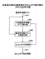
先ず最初に、本発明の第6の実施例について説明する。図13は、本発明の第6の実施例に従った、立ち上がり検出部のブロック図である。図13に示す立ち上がり検出部は、平均固定符号帳ゲイン算出部1301、固定符号帳ゲイン分散算出部1302、立ち上がり判定部1303より構成される。
【0036】
前述の1変換ブロック分に対応する固定符号帳ゲインの平均値が、平均固定符号帳ゲイン算出部1301により算出される。例えば、CELP符号化を使用する場合には、固定符号帳ゲインは、前述のようにCELPサブフレームを単位として算出される。このためN個のCELPサブフレーム単位(図8に示す場合にはN=4)の集合であるCELPフレーム単位で、入力信号が符号化される場合には、1つの変換ブロックがM個のCELPフレーム(図8に示す場合にはM=4)により構成されているので、変換ブロックkに対して計算される平均固定符号帳ゲインは、
【0037】
【数1】

【0038】
【外1】
【0039】
【数2】
【0040】
そして、立ち上がり判定部1303は、上述の式(2)により算出した固定符号帳ゲインの分散値と、予め定めたしきい値を比較することにより、当該第k番目の変換ブロック内に、固定符号帳ゲインの立ち上がりが存在するか否かを判定する。更に、このしきい値を、入力信号に基づいて、変換ブロック毎に変更することも可能である。そして、このように検出した立ち上がり検出情報1311を出力する。
【0041】
次に、本発明の第7の実施例について説明する。図14は、本発明の第7の実施例に従った、立ち上がり検出部のブロック図である。図14に示す立ち上がり検出部は、平均固定符号帳ゲイン算出部1301、フレーム平均2乗距離算出部1401、立ち上がり判定部1303より構成される。本実施例においては、平均固定符号帳ゲイン算出部1301の処理は、図13で示した第6の実施例と同様である。次に、フレーム平均2乗距離算出部1401において、各CELPフレームについて、このように算出された平均固定符号帳ゲインと、各CELPサブフレームの固定符号帳ゲインの間の、フレーム平均2乗距離が算出される。当該第k番目の変換ブロック内におけるフレーム平均2乗距離は、
【0042】
【数3】
【0043】
そして、立ち上がり判定部1303は、上述の式(3)により算出したフレーム平均2乗距離と、予め定めたしきい値を比較することにより、当該第k番目の変換ブロック内に、固定符号帳ゲインの立ち上がりが存在するか否かを判定する。更に、このしきい値を、入力信号に基づいて、変換ブロック毎に変更することも可能である。そして、このように検出した立ち上がり検出情報1311を出力する。
【0044】
次に、本発明の第8の実施例について説明する。図15は、本発明の第8の実施例に従った、立ち上がり検出部のブロック図である。図15に示す立ち上がり検出部は、平均固定符号帳ゲイン算出部1301及び、立ち上がり判定部1501より構成される。本実施例においては、平均固定符号帳ゲイン算出部1301の処理は、図13で示した第6の実施例と同様である。次に、立ち上がり判定部1501において、平均固定符号帳ゲイン算出部1301により算出された平均固定符号帳ゲイン若しくは平均固定符号帳ゲインを例えば定数倍する等により修正した値と、当該変換ブロック内の各CELPサブフレームの固定符号帳ゲインを比較することにより、固定符号帳ゲインの立ち上がりの存在ムを判定して、立ち上がり検出情報1311を出力する。
【0045】
次に、本発明の第9の実施例について説明する。図16は、本発明の第9の実施例に従った、立ち上がり検出部のブロック図である。図16に示す立ち上がり検出部は、固定符号帳ゲイン予測部1601、固定符号帳ゲイン予測残差検出部1602及び、立ち上がり判定部1603より構成される。固定符号帳ゲイン予測部1601は、過去のCELPサブフレームの固定符号帳ゲインから、当該CELPサブフレームの固定符号帳ゲインが予測され、予測固定符号帳ゲイン1604が算出される。例えば、予測固定符号帳ゲイン1604は、
【0046】
【数4】
【0047】
【数5】
【0048】
以上の説明においては、固定符号帳ゲインを使用して本発明の実施例を説明したが、固定符号帳ゲインの代わりに、復号された信号の電力を示す値を使用しても前述の説明が成り立つ。固定符号帳ゲインの代わりに、復号された信号の電力を示す値を使用する場合には、CELPサブフレーム内に入力信号の振幅の立ち上がりが存在するか否かを判定する方法として、例えば、CELPサブフレーム毎に復号された信号の平均電力を計算し、このように計算された平均電力の時間変動が所定のしきい値を超えているか否かに従って判定を行うような方法を使用することができる。或は、予め定められたサンプル数を用いて移動平均値を計算し、その時間変動を観察することにより、入力信号の振幅の立ち上がりが存在するか否かを判定する方法を使用することもできる。更に、符号化器で処理を行う場合には、第2の符号化手段に送出する立ち上がり検出情報を、符号化系列の一部として符号化系列に含めて、復号器に伝送することもできる。
【0049】
上述の説明では、音声・音響信号を使用する場合の実施例を説明したが、本発明を、音声・音響信号と同様な特徴を有する他のディジタル信号系列を処理する装置及び方法に対しても適用できる。
【0050】
【発明の効果】
本発明によれば、コア層の符号化方法としてCELP符号化を使用し、エンハンス層として他の符号化を使用するスケーラブル符号化のような、CELP符号化と他の符号化を有する符号化・復号装置及び方法において、固定符号帳ゲインの時間変動を観察して、入力信号中に存在する振幅の立ち上がりを検出し、エンハンス層に通知することが可能な装置及びその方法を提供できる。
【図面の簡単な説明】
【図1】 スケーラブル符号化のブロックを示す図である。
【図2】 CELP符号化の符号化装置のブロックを示す図である。
【図3】 CELP符号化された符号の復号装置のブロックを示す図である。
【図4】 変換符号化のための符号化装置のブロックを示す図である。
【図5】 変換符号化された符号化系列の復号装置のブロックを示す図である。
【図6】 入力信号電力の時間変動と、CELP符号化の固定符号帳ゲインの時間変動の関係を示す図である。
【図7】 本発明の第1の実施例の復号器のブロックを示す図である。
【図8】 CELP符号化で使用するフレームと、サブフレーム及び、変換符号化で使用する変換ブロックの関係の一例を示す図である。
【図9】 本発明の第2の実施例の符号化器のブロックを示す図である。
【図10】 本発明の第3の実施例の符号化器のブロックを示す図である。
【図11】 本発明の第4の実施例の符号化器のブロックを示す図である。
【図12】 本発明の第5の実施例の符号化器のブロックを示す図である。
【図13】 本発明の第6の実施例の立ち上がり検出部のブロックを示す図である。
【図14】 本発明の第7の実施例の立ち上がり検出部のブロックを示す図である。
【図15】 本発明の第8の実施例の立ち上がり検出部のブロックを示す図である。
【図16】 本発明の第9の実施例の立ち上がり検出部のブロックを示す図である。
【符号の説明】
101 コア層符号化器
104 エンハンス層
201 線形予測分析器
202 線形予測係数量子化部
203 線形予測合成フィルタ
204 適応符号帳
206 固定符号帳
208 聴覚重み付けフィルタ
212 加算部
213 減算部
301 適応符号帳
302 適応符号帳ゲイン
303 固定符号帳
304 固定符号帳ゲイン
305 線形予測合成フィルタ
400 符号化装置
401 直交変換部
402 変換係数量子化部
403 量子化変換係数符号化部
500 復号装置
501 量子化変換係数復号部
502 変換係数逆量子化部
503 逆直交変換部
700 復号器
701 CELP復号部
702 立ち上がりゲイン検出部
703 エンハンス層復号部
711 加算部
900 符号化器
901 CELP符号化部
902 エンハンス層符号化部
903 立ち上がり検出部
918 減算部
930 符号化器
940 符号化器
950 変換符号化部
951 選択部
953 立ち上がり検出情報符号化部
1301 平均固定符号帳ゲイン算出部
1302 固定符号帳ゲイン分散算出部
1303 立ち上がり判定部
1401 フレーム平均2乗距離算出部
1501 立ち上がり判定部
1601 固定符号帳ゲイン予測部
1602 固定符号帳ゲイン予測残差検出部
1603 立ち上がり判定部[0001]
BACKGROUND OF THE INVENTION
The present invention relates to a signal encoding / decoding device and an encoding or decoding method thereof for compressing and encoding or decoding an input signal with high efficiency.
[0002]
[Prior art]
At present, there are many apparatuses and methods for compressing, encoding, and decoding voice / acoustic signals with high efficiency. Among them, by providing hierarchical coding, hierarchical (scalable) coding that enables decoding only a part of a codeword sequence according to required quality and network conditions. is there. In scalable coding, an error signal between an input signal of an encoder and an output obtained by decoding a result of encoding by a lower layer encoder is sequentially encoded by an upper layer encoder. It has a going structure. The lowest layer is called the core layer, and the higher layer is called the enhancement layer. As an example of a typical scalable encoding method, there is scalable encoding of MPEG-4 Audio (ISO / IEC 14496-3) standardized by ISO / IEC. FIG. 1 shows a block diagram of this scalable coding. In this block diagram, as a
[0003]
FIG. 2 is a block diagram of a coding apparatus for CELP coding. The CELP encoder shown in FIG. 2 mainly includes a
[0004]
FIG. 3 is a block diagram of a
[0005]
On the other hand, FIG. 4 is a block diagram of an
[0006]
FIG. 5 is a block diagram of
[0007]
In this way, transform coding performs quantization and coding after transforming the input signal in the time domain into the frequency domain by orthogonal transform. Therefore, when the encoded sequence encoded in this way is inversely transformed into the time domain, the quantization noise generated by the quantization performed in the frequency domain is almost equal throughout the transform block, which is the unit of transform coding. Occurs at a uniform level. For this reason, if there is a part where the amplitude rises steeply in a part of the input signal in the conversion block, the part of the input signal in the conversion block before the part where the amplitude rises sharply, An annoying noise called pre-echo occurs. For example, when the transform block length is long, the section in which this pre-echo occurs is also long, resulting in a further deterioration in subjective quality. The problem that occurs in this transform coding also occurs when transform coding is used in the scalable coding described above.
[0008]
In order to solve such a problem, the above-described MPEG-4 Audio (ISO / IEC 14496-3) uses a technique called adaptive block length conversion. In this technique, a short conversion block is used when there is a steep rise in amplitude as described above in the input signal, and a long conversion block is used when there is no steep rise in amplitude. However, when such switching is performed, it is necessary to detect whether or not the input signal has a sharp rise in amplitude. One such detection method is as follows. First, the input signal is divided into transform blocks, and Fourier transform is performed on the transform blocks. Next, the obtained Fourier transform coefficient is divided into a plurality of frequency bands. For each band thus obtained, a signal-to-masking ratio (SMR, Signal-to-Masking Ratio), which is a ratio of the minimum audible noise power calculated based on the psychoacoustic model and the input signal power, is used. Based on this, a parameter called auditory entropy is calculated. The auditory entropy is compared with a preset threshold value to detect a sharp rise in amplitude. This method is also used for scalable coding in the aforementioned MPEG-4 Audio (ISO / IEC 14496-3).
[0009]
[Problems to be solved by the invention]
However, in the above-described prior art method, the conversion block length is simply adjusted to be short in order to shorten the interval in which the pre-echo occurs. Furthermore, since the transform block length changes in this way, auxiliary information indicating the transform block length is required on the decoding side in order to decode the encoded sequence. Therefore, the system configuration becomes complicated.
[0010]
The present invention aims to solve the above-mentioned drawbacks of the conventional system. The present invention is CELP coded in a coding / decoding apparatus and method having CELP coding and other coding, such as scalable coding using CELP coding as the coding method of the core layer. A time interval shorter than the transform block length used in the transform coding using the local decoded signal of the coded sequence or the power of the decoded signal or a fixed codebook gain which is a coding parameter by CELP coding. An apparatus and method for detecting the rising of the amplitude in the input signal waveform and notifying the encoding means and the decoding means related to other encoding, which enables execution of processing to cope with the occurrence of pre-echo Is to provide.
[0011]
[Means for Solving the Problems]
In the present invention, there is a strong correlation between the time variation of the input signal power, the time variation of the local decoded signal of the coded sequence encoded by CELP, and the time variation of the fixed codebook gain of CELP coding. Is used.
[0012]
The present invention relates to an input signal and a CELP in a coding / decoding apparatus and method having CELP coding and other coding, such as scalable coding using CELP coding as a core layer coding method, for example. By utilizing the strong correlation between the power of the local decoded signal of the encoded coded sequence or the decoded signal or the fixed codebook gain which is a coding parameter by CELP coding, By observing the power of the decoded signal or the time variation of the fixed codebook gain, the rising edge of the input signal is detected, and the detection result is notified to other encoding means and decoding means. Configured so that other encoding means and decoding means can execute processing to deal with the occurrence of pre-echo in a time interval shorter than the transform block length used That.
[0013]
DETAILED DESCRIPTION OF THE INVENTION
Embodiments of the present invention will be described below with reference to the drawings. In the following description of the embodiments of the present invention, it is assumed that the signal is a digital signal after analog / digital conversion.
[0014]
First, the principle of detecting the rise of the amplitude in the input signal according to the present invention will be described.
[0015]
FIG. 6 is a diagram illustrating the relationship between the time variation of the input signal power and the time variation of the fixed codebook gain of CELP encoding. There is a strong correlation between the time variation of the input signal power and the time variation of the fixed codebook gain of CELP encoding as shown in FIG. Therefore, the present invention observes and uses the time fluctuation of the fixed codebook gain of CELP coding for detecting the rise of the amplitude in the input signal.
[0016]
Next, a first embodiment of the present invention will be described. FIG. 7 is a block diagram of a decoder for decoding a codeword sequence encoded by scalable coding in which CELP coding is used as the coding method of the core layer according to the first embodiment of the present invention. Indicates.
[0017]
The
[0018]
FIG. 8 shows an example of the relationship between a frame used in CELP coding for coding the core layer, a subframe, and a transform block used in transform coding for coding the enhancement layer. One transform block is composed of four CELP frames, and one CELP frame is composed of four CELP subframes. One CELP subframe is composed of 64 samples, one CELP frame is composed of 256 samples, and one transform block is composed of 1024 samples.
[0019]
As shown in FIG. 7,
[0020]
On the other hand, the enhancement
[0021]
For example, when there is a relationship as shown in FIG. 8 between the transform block, the CELP frame, and the CELP subframe, one CELP subframe is processed during the CELP encoding process when the core layer is encoded. A fixed codebook gain is calculated for each frame, and encoded for each CELP frame. Therefore, the enhancement
[0022]
Next, a second embodiment of the present invention will be described. FIG. 9 shows a block diagram of an
[0023]
The
[0024]
On the other hand, the
[0025]
Next, a third embodiment of the present invention will be described. FIG. 10 shows that the input signal is encoded using CELP encoding and other encodings such as transform encoding according to the third embodiment of the present invention, and the resulting encoded sequence. The block diagram of the
[0026]
The
[0027]
In FIG. 10, the
[0028]
Next, a fourth embodiment of the present invention will be described. FIG. 11 shows that according to a fourth embodiment of the present invention, the input signal is encoded using CELP encoding and other encodings such as transform encoding, and the resulting encoded sequence. The block diagram of the
[0029]
The
[0030]
In FIG. 11, the
[0031]
Next, a fifth embodiment of the present invention will be described. FIG. 12 shows that the input signal is encoded using CELP encoding and other encodings, such as transform encoding, according to a fifth embodiment of the present invention, and the resulting encoded sequence. The block diagram of the
[0032]
The
[0033]
In FIG. 12, an
[0034]
Next, another embodiment of the present invention will be described. The following embodiments are embodiments of the rising edge detection unit in the first to fifth embodiments described above. In the following embodiments of the rising edge detection unit, the relationship between the conversion block, the CELP frame, and the CELP subframe will be described as having the same relationship as shown with reference to FIG.
[0035]
First, a sixth embodiment of the present invention will be described. FIG. 13 is a block diagram of a rising edge detection unit according to the sixth embodiment of the present invention. 13 includes an average fixed codebook
[0036]
The average value of the fixed codebook gain corresponding to one conversion block is calculated by the average fixed codebook
[0037]
[Expression 1]
[0038]
[Outside 1]
[0039]
[Expression 2]
[0040]
Then, the rising
[0041]
Next, a seventh embodiment of the present invention will be described. FIG. 14 is a block diagram of the rising edge detection unit according to the seventh embodiment of the present invention. 14 includes an average fixed codebook
[0042]
[Equation 3]
[0043]
Then, the rising
[0044]
Next, an eighth embodiment of the present invention will be described. FIG. 15 is a block diagram of the rising edge detection unit according to the eighth embodiment of the present invention. The rising detection unit shown in FIG. 15 includes an average fixed codebook
[0045]
Next, a ninth embodiment of the present invention will be described. FIG. 16 is a block diagram of the rising edge detection unit according to the ninth embodiment of the present invention. The rise detection unit shown in FIG. 16 includes a fixed codebook
[0046]
[Expression 4]
[0047]
[Equation 5]
[0048]
In the above description, the embodiments of the present invention have been described using the fixed codebook gain. However, the above description can be made even if a value indicating the power of the decoded signal is used instead of the fixed codebook gain. It holds. When a value indicating the power of the decoded signal is used instead of the fixed codebook gain, as a method for determining whether or not there is a rising amplitude of the input signal in the CELP subframe, for example, CELP It is possible to use a method that calculates the average power of the decoded signal for each subframe and makes a determination according to whether the time variation of the average power calculated in this way exceeds a predetermined threshold. it can. Alternatively, a method can be used in which a moving average value is calculated using a predetermined number of samples and the time variation is observed to determine whether or not there is a rise in the amplitude of the input signal. . Further, when processing is performed by the encoder, the rising edge detection information sent to the second encoding means can be included in the encoded sequence as part of the encoded sequence and transmitted to the decoder.
[0049]
In the above description, the embodiment in the case of using a voice / acoustic signal has been described. Applicable.
[0050]
【The invention's effect】
According to the present invention, coding with CELP coding and other coding, such as scalable coding using CELP coding as the coding method of the core layer and using other coding as the enhancement layer. In the decoding apparatus and method, it is possible to provide an apparatus and method capable of observing the time variation of the fixed codebook gain, detecting the rise of the amplitude present in the input signal, and notifying the enhancement layer.
[Brief description of the drawings]
FIG. 1 is a diagram illustrating a block of scalable coding.
FIG. 2 is a diagram illustrating a block of a coding apparatus for CELP coding.
FIG. 3 is a diagram showing a block of a CELP-encoded code decoding device.
FIG. 4 is a diagram illustrating a block of an encoding device for transform encoding.
FIG. 5 is a diagram illustrating a block of a decoding apparatus for a coded sequence obtained by transform coding.
FIG. 6 is a diagram illustrating a relationship between time variation of input signal power and time variation of fixed codebook gain of CELP encoding.
FIG. 7 is a diagram showing a block of a decoder according to the first embodiment of the present invention.
FIG. 8 is a diagram illustrating an example of a relationship between a frame used in CELP encoding, a subframe, and a transform block used in transform coding.
FIG. 9 is a diagram illustrating a block of an encoder according to a second embodiment of the present invention.
FIG. 10 is a diagram illustrating a block of an encoder according to a third embodiment of the present invention.
FIG. 11 is a diagram illustrating a block of an encoder according to a fourth embodiment of the present invention.
FIG. 12 is a block diagram illustrating an encoder according to a fifth embodiment of the present invention.
FIG. 13 is a diagram showing a block of a rising edge detection unit according to a sixth embodiment of the present invention.
FIG. 14 is a diagram showing a block of a rising edge detection unit according to a seventh embodiment of the present invention.
FIG. 15 is a block diagram illustrating a rising edge detection unit according to an eighth embodiment of the present invention.
FIG. 16 is a diagram illustrating a block of a rising edge detection unit according to a ninth embodiment of this invention.
[Explanation of symbols]
101 Core layer encoder
104 Enhanced layer
201 Linear prediction analyzer
202 Linear prediction coefficient quantization unit
203 Linear prediction synthesis filter
204 Adaptive codebook
206 Fixed codebook
208 Auditory weighting filter
212 Adder
213 Subtraction unit
301 Adaptive codebook
302 Adaptive codebook gain
303 Fixed codebook
304 Fixed codebook gain
305 Linear prediction synthesis filter
400 Encoder
401 orthogonal transform unit
402 Transform coefficient quantization unit
403 Quantized transform coefficient coding unit
500 Decoding device
501 Quantized transform coefficient decoding unit
502 Transform coefficient inverse quantization unit
503 Inverse orthogonal transform unit
700 Decoder
701 CELP decoding unit
702 Rising gain detector
703 Enhanced layer decoder
711 Adder
900 Encoder
901 CELP encoding unit
902 Enhanced layer coding unit
903 Rise detection unit
918 Subtraction unit
930 encoder
940 encoder
950 transform coding unit
951 Selector
953 Rising detection information encoding unit
1301 Average fixed codebook gain calculation unit
1302 Fixed Codebook Gain Variance Calculation Unit
1303 Rise determination unit
1401 Frame mean square distance calculation unit
1501 Rise determination unit
1601 Fixed Codebook Gain Prediction Unit
1602 Fixed codebook gain prediction residual detection unit
1603 Rising determination unit
Claims (30)
前記第1の復号手段により得られる励振ベクトルの利得の時間変動に基づいて、入力信号の中の振幅の立ち上がりを検出する手段と、
前記立ち上がりを、前記第2の復号手段に通知する手段と
を有し、
前記第2の復号手段は、通知された立ち上がりに基づいて、前記他の符号化方法により符号化された符号語を復号する、立ち上がり検出・通知装置を設けた復号装置。First decoding means for decoding a codeword obtained by encoding an input signal by a code-excited linear predictive encoding method, and a codeword encoded by another encoding method different from the code-excited linear predictive encoding method In a decoding device having a single or a plurality of second decoding means,
Means for detecting the rise of the amplitude in the input signal based on the time variation of the gain of the excitation vector obtained by the first decoding means;
Means for notifying the rising to the second decoding means,
The decoding device provided with a rising edge detection / notification device, wherein the second decoding means decodes a codeword encoded by the other encoding method based on the notified rising edge.
前記第1の復号手段により得られる復号信号波形の時間変動に基づいて、入力信号の立ち上がりを検出する手段と、
前記立ち上がりを、前記第2の復号手段に通知する手段と
を有し、
前記第2の復号手段は、通知された立ち上がりに基づいて、前記他の符号化方法により符号化された符号語を復号する、立ち上がり検出・通知装置を設けた復号装置。First decoding means for decoding a codeword obtained by encoding an input signal by a code-excited linear predictive encoding method, and a codeword encoded by another encoding method different from the code-excited linear predictive encoding method In a decoding device having a single or a plurality of second decoding means,
Means for detecting the rising edge of the input signal based on the time variation of the decoded signal waveform obtained by the first decoding means;
Means for notifying the rising to the second decoding means,
The decoding device provided with a rising edge detection / notification device, wherein the second decoding means decodes a codeword encoded by the other encoding method based on the notified rising edge.
前記第1の符号化手段により得られる励振ベクトルの利得の時間変動に基づいて、入力信号の中の振幅の立ち上がりを検出する手段と、
前記立ち上がりを、前記第2の符号化手段に通知する手段と
を有し、
前記第2の符号化手段は、通知された立ち上がりに基づいて、前記入力信号を前記他の符号化方法により符号化する、立ち上がり検出・通知装置を設けた符号化装置。A first encoding means for encoding an input signal by a code-excited linear predictive encoding method, and a single or plural second codes for encoding by an encoding method different from the code-excited linear predictive encoding method; And an encoding device comprising:
Means for detecting the rise of the amplitude in the input signal based on the time variation of the gain of the excitation vector obtained by the first encoding means;
Means for notifying the rising edge to the second encoding means;
The encoding device provided with a rising edge detection / notification device, wherein the second encoding means encodes the input signal by the other encoding method based on the notified rising edge.
前記第1の符号化手段により得られるローカル復号信号の時間変動に基づいて、入力信号の中の振幅の立ち上がりを検出する手段と、
前記立ち上がりを、前記第2の符号化手段に通知する手段と
を有し、
前記第2の符号化手段は、通知された立ち上がりに基づいて、前記入力信号を、前記他の符号化方法により符号化する、立ち上がり検出・通知装置を設けた符号化装置。A first encoding means for encoding an input signal by a code-excited linear predictive encoding method, and a single or plural second codes for encoding by an encoding method different from the code-excited linear predictive encoding method; And an encoding device comprising:
Means for detecting the rise of the amplitude in the input signal based on the time variation of the local decoded signal obtained by the first encoding means;
Means for notifying the rising edge to the second encoding means;
The encoding device provided with a rising edge detection / notification device, wherein the second encoding means encodes the input signal by the other encoding method based on the notified rising edge.
前記第1の復号手段により得られる励振ベクトルの利得の時間変動に基づいて、入力信号の中の振幅の立ち上がりを検出するステップと、
前記立ち上がりを、前記第2の復号手段に通知するステップと
前記第2の復号手段が、通知された立ち上がりに基づいて、前記他の符号化方法により符号化された符号語を復号するステップ
を有する復号方法。First decoding means for decoding a codeword obtained by encoding an input signal by a code-excited linear predictive encoding method, and a codeword encoded by another encoding method different from the code-excited linear predictive encoding method In a decoding method in a decoding device having a single or a plurality of second decoding means,
Detecting a rise in amplitude in the input signal based on time variation of the gain of the excitation vector obtained by the first decoding means;
Notifying the second decoding means of the rising edge, and the second decoding means decoding the codeword encoded by the other encoding method based on the notified rising edge. decrypt how to.
前記第1の復号手段により得られる復号信号波形の時間変動に基づいて、入力信号の立ち上がりを検出するステップと、
前記立ち上がりを、前記第2の復号手段に通知するステップと、
前記第2の復号手段が、通知された立ち上がりに基づいて、前記他の符号化方法により符号化された符号語を復号するステップと
を有する復号方法。First decoding means for decoding a codeword obtained by encoding an input signal by a code-excited linear predictive encoding method, and a codeword encoded by another encoding method different from the code-excited linear predictive encoding method In a decoding method in a decoding device having a single or a plurality of second decoding means,
Detecting the rising edge of the input signal based on the time variation of the decoded signal waveform obtained by the first decoding means;
Notifying the second decoding means of the rising edge ;
It said second decoding means, notified based on the rise, decrypt how having a a step of decoding the encoded codeword by the other encoding methods.
前記第1の符号化手段により得られる励振ベクトルの利得の時間変動に基づいて、入力信号の中の振幅の立ち上がりを検出するステップと、
前記立ち上がりを、前記第2の符号化手段に通知するステップと、
前記第2の符号化手段が、通知された立ち上がりに基づいて、前記入力信号を前記他の符号化方法により符号化するステップと
を有する符号化方法。A first encoding means for encoding an input signal by a code-excited linear predictive encoding method; and a single or plural second codes for encoding by an encoding method different from the code-excited linear predictive encoding method In an encoding method in an encoding device having encoding means,
Detecting a rise in amplitude in the input signal based on time variation of the gain of the excitation vector obtained by the first encoding means;
Notifying the rising edge to the second encoding means ;
It said second encoding means, notified based on the rise, marks Goka how the input signal having a the step of encoding by the other encoding methods.
前記第1の符号化手段により得られるローカル復号信号の時間変動に基づいて、入力信号の中の振幅の立ち上がりを検出するステップと、
前記立ち上がりを、前記第2の符号化手段に通知するステップと、
前記第2の符号化手段が、通知された立ち上がりに基づいて、前記入力信号を、前記他の符号化方法により符号化するステップと
を有する符号化方法。A first encoding means for encoding an input signal by a code-excited linear predictive encoding method; and a single or plural second codes for encoding by an encoding method different from the code-excited linear predictive encoding method In an encoding method in an encoding device having encoding means,
Detecting a rise in amplitude in the input signal based on time variation of the local decoded signal obtained by the first encoding means;
Notifying the rising edge to the second encoding means ;
It said second encoding means, notified on the basis of the rise, the input signal, marks Goka how having a a step of encoding by the other encoding methods.
Priority Applications (5)
| Application Number | Priority Date | Filing Date | Title |
|---|---|---|---|
| JP2002033154A JP4290917B2 (en) | 2002-02-08 | 2002-02-08 | Decoding device, encoding device, decoding method, and encoding method |
| DE60308567T DE60308567T2 (en) | 2002-02-08 | 2003-02-06 | Decoding device, coding device, decoding method and coding method |
| EP03250752A EP1335353B1 (en) | 2002-02-08 | 2003-02-06 | Decoding apparatus, encoding apparatus, decoding method and encoding method |
| US10/359,638 US7406410B2 (en) | 2002-02-08 | 2003-02-07 | Encoding and decoding method and apparatus using rising-transition detection and notification |
| CN03102121.2A CN1220972C (en) | 2002-02-08 | 2003-02-08 | Decoding apparatus and coding apparatus, decoding method and coding method |
Applications Claiming Priority (1)
| Application Number | Priority Date | Filing Date | Title |
|---|---|---|---|
| JP2002033154A JP4290917B2 (en) | 2002-02-08 | 2002-02-08 | Decoding device, encoding device, decoding method, and encoding method |
Publications (2)
| Publication Number | Publication Date |
|---|---|
| JP2003233400A JP2003233400A (en) | 2003-08-22 |
| JP4290917B2 true JP4290917B2 (en) | 2009-07-08 |
Family
ID=27606554
Family Applications (1)
| Application Number | Title | Priority Date | Filing Date |
|---|---|---|---|
| JP2002033154A Expired - Fee Related JP4290917B2 (en) | 2002-02-08 | 2002-02-08 | Decoding device, encoding device, decoding method, and encoding method |
Country Status (5)
| Country | Link |
|---|---|
| US (1) | US7406410B2 (en) |
| EP (1) | EP1335353B1 (en) |
| JP (1) | JP4290917B2 (en) |
| CN (1) | CN1220972C (en) |
| DE (1) | DE60308567T2 (en) |
Families Citing this family (31)
| Publication number | Priority date | Publication date | Assignee | Title |
|---|---|---|---|---|
| KR100668300B1 (en) * | 2003-07-09 | 2007-01-12 | 삼성전자주식회사 | Apparatus and method for bit rate extended speech encoding and decoding |
| US20060015329A1 (en) * | 2004-07-19 | 2006-01-19 | Chu Wai C | Apparatus and method for audio coding |
| JP4533386B2 (en) * | 2004-07-22 | 2010-09-01 | 富士通株式会社 | Audio encoding apparatus and audio encoding method |
| JP4558734B2 (en) * | 2004-07-28 | 2010-10-06 | パナソニック株式会社 | Signal decoding device |
| JP4781272B2 (en) * | 2004-09-17 | 2011-09-28 | パナソニック株式会社 | Speech coding apparatus, speech decoding apparatus, communication apparatus, and speech coding method |
| KR100707184B1 (en) * | 2005-03-10 | 2007-04-13 | 삼성전자주식회사 | Audio encoding and decoding apparatus, method and recording medium |
| KR100707186B1 (en) * | 2005-03-24 | 2007-04-13 | 삼성전자주식회사 | Audio encoding and decoding apparatus, method and recording medium |
| KR100956525B1 (en) * | 2005-04-01 | 2010-05-07 | 퀄컴 인코포레이티드 | Method and apparatus for split band encoding of speech signal |
| US8892448B2 (en) | 2005-04-22 | 2014-11-18 | Qualcomm Incorporated | Systems, methods, and apparatus for gain factor smoothing |
| ES2327566T3 (en) | 2005-04-28 | 2009-10-30 | Siemens Aktiengesellschaft | PROCEDURE AND DEVICE FOR NOISE SUPPRESSION. |
| CN101199005B (en) * | 2005-06-17 | 2011-11-09 | 松下电器产业株式会社 | Post filter, decoder, and post filtering method |
| FR2888704A1 (en) * | 2005-07-12 | 2007-01-19 | France Telecom | |
| FR2897733A1 (en) | 2006-02-20 | 2007-08-24 | France Telecom | Echo discriminating and attenuating method for hierarchical coder-decoder, involves attenuating echoes based on initial processing in discriminated low energy zone, and inhibiting attenuation of echoes in false alarm zone |
| WO2007105586A1 (en) * | 2006-03-10 | 2007-09-20 | Matsushita Electric Industrial Co., Ltd. | Coding device and coding method |
| US8370138B2 (en) * | 2006-03-17 | 2013-02-05 | Panasonic Corporation | Scalable encoding device and scalable encoding method including quality improvement of a decoded signal |
| DE602006002381D1 (en) * | 2006-04-24 | 2008-10-02 | Nero Ag | ADVANCED DEVICE FOR CODING DIGITAL AUDIO DATA |
| US20080059154A1 (en) * | 2006-09-01 | 2008-03-06 | Nokia Corporation | Encoding an audio signal |
| DE102006051673A1 (en) * | 2006-11-02 | 2008-05-15 | Fraunhofer-Gesellschaft zur Förderung der angewandten Forschung e.V. | Apparatus and method for reworking spectral values and encoders and decoders for audio signals |
| CN101325058B (en) * | 2007-06-15 | 2012-04-25 | 华为技术有限公司 | Speech coding sending and receiving decoding method and device |
| US7885819B2 (en) * | 2007-06-29 | 2011-02-08 | Microsoft Corporation | Bitstream syntax for multi-process audio decoding |
| US20090076828A1 (en) * | 2007-08-27 | 2009-03-19 | Texas Instruments Incorporated | System and method of data encoding |
| CN101458930B (en) * | 2007-12-12 | 2011-09-14 | 华为技术有限公司 | Excitation signal generation in bandwidth spreading and signal reconstruction method and apparatus |
| KR101655913B1 (en) * | 2008-09-17 | 2016-09-08 | 오렌지 | Pre-echo attenuation in a digital audio signal |
| KR101643434B1 (en) * | 2008-09-18 | 2016-07-27 | 미쓰비시덴키 가부시키가이샤 | Transmission device and reception device |
| JP4977157B2 (en) * | 2009-03-06 | 2012-07-18 | 株式会社エヌ・ティ・ティ・ドコモ | Sound signal encoding method, sound signal decoding method, encoding device, decoding device, sound signal processing system, sound signal encoding program, and sound signal decoding program |
| WO2010108332A1 (en) * | 2009-03-27 | 2010-09-30 | 华为技术有限公司 | Encoding and decoding method and device |
| GB2473267A (en) * | 2009-09-07 | 2011-03-09 | Nokia Corp | Processing audio signals to reduce noise |
| US8977546B2 (en) | 2009-10-20 | 2015-03-10 | Panasonic Intellectual Property Corporation Of America | Encoding device, decoding device and method for both |
| FR3000328A1 (en) * | 2012-12-21 | 2014-06-27 | France Telecom | EFFECTIVE MITIGATION OF PRE-ECHO IN AUDIONUMERIC SIGNAL |
| CN104021796B (en) * | 2013-02-28 | 2017-06-20 | 华为技术有限公司 | Speech enhan-cement treating method and apparatus |
| EP2980797A1 (en) | 2014-07-28 | 2016-02-03 | Fraunhofer-Gesellschaft zur Förderung der angewandten Forschung e.V. | Audio decoder, method and computer program using a zero-input-response to obtain a smooth transition |
Family Cites Families (9)
| Publication number | Priority date | Publication date | Assignee | Title |
|---|---|---|---|---|
| FR2729245B1 (en) * | 1995-01-06 | 1997-04-11 | Lamblin Claude | LINEAR PREDICTION SPEECH CODING AND EXCITATION BY ALGEBRIC CODES |
| JP3307138B2 (en) | 1995-02-27 | 2002-07-24 | ソニー株式会社 | Signal encoding method and apparatus, and signal decoding method and apparatus |
| JP3139602B2 (en) | 1995-03-24 | 2001-03-05 | 日本電信電話株式会社 | Acoustic signal encoding method and decoding method |
| JP3335852B2 (en) | 1996-09-26 | 2002-10-21 | 株式会社東芝 | Speech coding method, gain control method, and gain coding / decoding method using auditory characteristics |
| DE19736669C1 (en) * | 1997-08-22 | 1998-10-22 | Fraunhofer Ges Forschung | Beat detection method for time discrete audio signal |
| US6311154B1 (en) * | 1998-12-30 | 2001-10-30 | Nokia Mobile Phones Limited | Adaptive windows for analysis-by-synthesis CELP-type speech coding |
| JP2000259197A (en) | 1999-03-10 | 2000-09-22 | Matsushita Electric Ind Co Ltd | Attack / release signal detection and correction method in audio coding |
| US6691082B1 (en) * | 1999-08-03 | 2004-02-10 | Lucent Technologies Inc | Method and system for sub-band hybrid coding |
| US6496794B1 (en) * | 1999-11-22 | 2002-12-17 | Motorola, Inc. | Method and apparatus for seamless multi-rate speech coding |
-
2002
- 2002-02-08 JP JP2002033154A patent/JP4290917B2/en not_active Expired - Fee Related
-
2003
- 2003-02-06 EP EP03250752A patent/EP1335353B1/en not_active Expired - Lifetime
- 2003-02-06 DE DE60308567T patent/DE60308567T2/en not_active Expired - Lifetime
- 2003-02-07 US US10/359,638 patent/US7406410B2/en not_active Expired - Fee Related
- 2003-02-08 CN CN03102121.2A patent/CN1220972C/en not_active Expired - Fee Related
Also Published As
| Publication number | Publication date |
|---|---|
| DE60308567T2 (en) | 2007-06-06 |
| EP1335353A3 (en) | 2005-01-12 |
| JP2003233400A (en) | 2003-08-22 |
| US20030154074A1 (en) | 2003-08-14 |
| US7406410B2 (en) | 2008-07-29 |
| EP1335353B1 (en) | 2006-09-27 |
| DE60308567D1 (en) | 2006-11-09 |
| CN1220972C (en) | 2005-09-28 |
| CN1437184A (en) | 2003-08-20 |
| EP1335353A2 (en) | 2003-08-13 |
Similar Documents
| Publication | Publication Date | Title |
|---|---|---|
| JP4290917B2 (en) | Decoding device, encoding device, decoding method, and encoding method | |
| KR101251790B1 (en) | Noise filler, noise filling parameter calculator, method for providing a noise-filled spectral representation of an audio signal, method for providing a noise filling parameter, storage medium | |
| US8862463B2 (en) | Adaptive time/frequency-based audio encoding and decoding apparatuses and methods | |
| KR101525185B1 (en) | Apparatus and method for coding a portion of an audio signal using a transient detection and a quality result | |
| EP2313887B1 (en) | Variable bit rate lpc filter quantizing and inverse quantizing device and method | |
| US10706865B2 (en) | Apparatus and method for selecting one of a first encoding algorithm and a second encoding algorithm using harmonics reduction | |
| EP3779983B1 (en) | Harmonicity-dependent controlling of a harmonic filter tool | |
| US20100010807A1 (en) | Method and apparatus to encode and decode an audio/speech signal | |
| KR101350285B1 (en) | Signal coding, decoding method and device, system thereof | |
| US20100268542A1 (en) | Apparatus and method of audio encoding and decoding based on variable bit rate | |
| EP2727105B1 (en) | Transform audio codec and methods for encoding and decoding a time segment of an audio signal | |
| JP3628268B2 (en) | Acoustic signal encoding method, decoding method and apparatus, program, and recording medium | |
| KR20150032736A (en) | Decoding method, decoding device, program, and recording method thereof | |
| US8595000B2 (en) | Method and apparatus to search fixed codebook and method and apparatus to encode/decode a speech signal using the method and apparatus to search fixed codebook | |
| CN101582263B (en) | Method and device for noise enhancement post-processing in speech decoding | |
| JP3010654B2 (en) | Compression encoding apparatus and method | |
| JP2892462B2 (en) | Code-excited linear predictive encoder | |
| Fuchs et al. | A speech coder post-processor controlled by side-information |
Legal Events
| Date | Code | Title | Description |
|---|---|---|---|
| A621 | Written request for application examination |
Free format text: JAPANESE INTERMEDIATE CODE: A621 Effective date: 20041006 |
|
| A977 | Report on retrieval |
Free format text: JAPANESE INTERMEDIATE CODE: A971007 Effective date: 20070129 |
|
| A131 | Notification of reasons for refusal |
Free format text: JAPANESE INTERMEDIATE CODE: A131 Effective date: 20070213 |
|
| A521 | Request for written amendment filed |
Free format text: JAPANESE INTERMEDIATE CODE: A523 Effective date: 20070409 |
|
| A02 | Decision of refusal |
Free format text: JAPANESE INTERMEDIATE CODE: A02 Effective date: 20080902 |
|
| A521 | Request for written amendment filed |
Free format text: JAPANESE INTERMEDIATE CODE: A523 Effective date: 20081027 |
|
| A911 | Transfer to examiner for re-examination before appeal (zenchi) |
Free format text: JAPANESE INTERMEDIATE CODE: A911 Effective date: 20081110 |
|
| TRDD | Decision of grant or rejection written | ||
| A01 | Written decision to grant a patent or to grant a registration (utility model) |
Free format text: JAPANESE INTERMEDIATE CODE: A01 Effective date: 20090331 |
|
| A01 | Written decision to grant a patent or to grant a registration (utility model) |
Free format text: JAPANESE INTERMEDIATE CODE: A01 |
|
| A61 | First payment of annual fees (during grant procedure) |
Free format text: JAPANESE INTERMEDIATE CODE: A61 Effective date: 20090402 |
|
| R150 | Certificate of patent or registration of utility model |
Ref document number: 4290917 Country of ref document: JP Free format text: JAPANESE INTERMEDIATE CODE: R150 Free format text: JAPANESE INTERMEDIATE CODE: R150 |
|
| FPAY | Renewal fee payment (event date is renewal date of database) |
Free format text: PAYMENT UNTIL: 20120410 Year of fee payment: 3 |
|
| FPAY | Renewal fee payment (event date is renewal date of database) |
Free format text: PAYMENT UNTIL: 20120410 Year of fee payment: 3 |
|
| FPAY | Renewal fee payment (event date is renewal date of database) |
Free format text: PAYMENT UNTIL: 20130410 Year of fee payment: 4 |
|
| R250 | Receipt of annual fees |
Free format text: JAPANESE INTERMEDIATE CODE: R250 |
|
| FPAY | Renewal fee payment (event date is renewal date of database) |
Free format text: PAYMENT UNTIL: 20130410 Year of fee payment: 4 |
|
| FPAY | Renewal fee payment (event date is renewal date of database) |
Free format text: PAYMENT UNTIL: 20140410 Year of fee payment: 5 |
|
| R250 | Receipt of annual fees |
Free format text: JAPANESE INTERMEDIATE CODE: R250 |
|
| R250 | Receipt of annual fees |
Free format text: JAPANESE INTERMEDIATE CODE: R250 |
|
| R250 | Receipt of annual fees |
Free format text: JAPANESE INTERMEDIATE CODE: R250 |
|
| R250 | Receipt of annual fees |
Free format text: JAPANESE INTERMEDIATE CODE: R250 |
|
| R250 | Receipt of annual fees |
Free format text: JAPANESE INTERMEDIATE CODE: R250 |
|
| R250 | Receipt of annual fees |
Free format text: JAPANESE INTERMEDIATE CODE: R250 |
|
| LAPS | Cancellation because of no payment of annual fees |