JP4286183B2 - Armrest device - Google Patents
Armrest device Download PDFInfo
- Publication number
- JP4286183B2 JP4286183B2 JP2004153584A JP2004153584A JP4286183B2 JP 4286183 B2 JP4286183 B2 JP 4286183B2 JP 2004153584 A JP2004153584 A JP 2004153584A JP 2004153584 A JP2004153584 A JP 2004153584A JP 4286183 B2 JP4286183 B2 JP 4286183B2
- Authority
- JP
- Japan
- Prior art keywords
- armrest
- switching operation
- seat
- operation member
- pair
- Prior art date
- Legal status (The legal status is an assumption and is not a legal conclusion. Google has not performed a legal analysis and makes no representation as to the accuracy of the status listed.)
- Expired - Lifetime
Links
Images


Landscapes
- Component Parts Of Construction Machinery (AREA)
- Seats For Vehicles (AREA)
Description
本発明は、トラクタ等の運転席に配備されるアームレスト装置に関するものである。 The present invention relates to an armrest device provided in a driver's seat such as a tractor.
近年、トラクタ等の運転席においては、キャビンの内部に配備された操作装置の小型化や操作性の向上を図るために、運転席側部に配備されたアームレストに操作装置の一部を操作部として配備したものが開発されている。
この種のアームレストにおいては、オペレータの体型に合わせたアームレストの位置調整を可能とすべく、運転席に対してアームレストの前後位置を調整するための前後位置調整機構が設けられており、これによってオペレータは、自らの体型に合わせてアームレストの前後位置を調整し、アームレストの先端に配備された操作部を最も操作し易い位置に設定して作業を行うことができる(特許文献1または特許文献2参照)。
In recent years, in a driver's seat such as a tractor, in order to reduce the size and improve the operability of the operating device provided in the cabin, a part of the operating device is attached to the armrest provided in the driver's seat side part. What has been deployed as has been developed.
In this type of armrest, a front / rear position adjustment mechanism for adjusting the front / rear position of the armrest relative to the driver's seat is provided so that the position of the armrest can be adjusted according to the body shape of the operator. Can adjust the front / rear position of the armrest in accordance with its own body shape, and can set the operation part provided at the tip of the armrest to the position where it can be most easily operated (see
また、運転席に対する前後方向の位置調整と共に、上下方向の位置調整を可能とするアームレストを備えた作業車両の運転席が提案されている。該運転席において、肘掛け部材(アームレスト)は、平板状の取付部と該取付部の上端に配備されたクッションとから構成され、該取付部には、上下方向の長溝と、該長溝に連接される複数の水平逃げ溝が形成されており、該逃げ溝に挿通された螺子を運転席側方のブラケットに螺合することにより、運転席側方に前記肘掛け部材が固定されている(特許文献3参照)。
以上の構成によれば、先ず、固定された螺子を緩めて肘掛け部材を水平に移動させることにより、前記螺子を水平逃げ溝から長溝に向けて相対移動させ、次に、該長溝に沿って肘掛け部材を昇降させることにより、該肘掛け部材を所望の上下位置に移動させる。
In addition, there has been proposed a driver's seat for a work vehicle that includes an armrest that enables position adjustment in the vertical direction as well as position adjustment in the front-rear direction with respect to the driver seat. In the driver's seat, an armrest member (armrest) is composed of a flat mounting portion and a cushion provided at the upper end of the mounting portion, and the mounting portion is connected to the vertical groove and the long groove. A plurality of horizontal relief grooves are formed, and the armrest member is fixed to the side of the driver's seat by screwing a screw inserted through the relief groove into a bracket on the side of the driver's seat (Patent Document) 3).
According to the above configuration, first, by loosening the fixed screw and moving the armrest member horizontally, the screw is relatively moved from the horizontal escape groove toward the long groove, and then the armrest is moved along the long groove. By raising and lowering the member, the armrest member is moved to a desired vertical position.
その後、該上下位置に形成されている水平逃げ溝に向けてさらに肘掛け部材を相対移動させ、所望の前後位置にて螺子を再び螺合させる。これによって、肘掛け部材は所望の上下位置及び前後位置に調整されることとなる。
しかしながら、上記特許文献3の作業車両の運転席において、肘掛け部材の位置を調整するためには、先ず、螺子を緩めることにより肘掛け部材を位置設定状態から位置調整可能状態に設定し、次に、該肘掛け部材を所望の上下及び前後位置に移動させ、その後、螺子を螺合することにより、再び肘掛け部材を位置設定状態に固定しなければならず、肘掛け部材の位置調整のための操作が非常に煩雑であった。
そこで本発明の目的は、上記問題点に鑑み、アームレストを位置設定状態または位置調整可能状態に容易に設定することができるアームレスト装置を提供するようにしたものである。
However, in order to adjust the position of the armrest member in the driver's seat of the work vehicle of
In view of the above problems, an object of the present invention is to provide an armrest device that can easily set an armrest to a position setting state or a position adjustable state.
本発明における課題解決のための具体的手段は、次の通りである。
第1に、操作部43を有して運転席31の側方に配備されていてアーム本体42を有するアームレスト41と、該アームレスト41を運転席31に対して前後方向及び上下方向の位置調整を可能に支持する位置調整機構51とを備え、該位置調整機構51には、アームレスト41を位置設定状態と位置調整可能状態とに切換える切換操作部材72が設けられており、
前記位置調整機構51は、運転席31側方に取り付けられた支持台52と、前記アーム本体42に連結されていて左右一対の平板部57a,57bを有する連結部材53と、該連結部材53と支持台52とを連結する平行リンク手段54と、平行リンク手段54の前後一対のリンク体59,60の揺動角を設定する角度設定手段71とを有しており、
前記切換操作部材72は、前記平行リンク手段54の一方のリンク体60を貫通して設けられており、前記角度設定手段71は、前記連結部材53の左右平板部57a,57bに形成されて前記切換操作部材72の移動を案内するガイド溝74と摺動溝75とをそれぞれ備え、前記ガイド溝74には、前記切換操作部材72と係合して前記前後一方のリンク体60の揺動角度を設定するための係合部74bが複数形成されており、
前記切換操作部材72は、前記摺動溝75側に対して前記ガイド溝74側を揺動して係合部74bに係脱させるための操作レバー72aが設けられていることを特徴とする。
Specific means for solving the problems in the present invention are as follows.
First, the
The
The
The
第2に、前記切換操作部材72の断面形状と前記一方のリンク体60の切換操作部材挿通孔77とは小判形状に形成され、前記切換操作部材72はバネ78によって前記ガイド溝74の係合部74bに係合するように付勢されていることを特徴とする。
前記特徴を有する本発明は、次のような作用を有する。
第1に、操作部43を有して運転席31の側方に配備されるアームレスト41と、該アームレスト41を運転席31に対して前後方向及び上下方向の位置調整を可能に支持する位置調整機構51とを備え、該位置調整機構51には、アームレスト41を位置設定状態と位置調整可能状態とに切換える切換操作部材72が設けられていることにより、位置調整機構51の切換操作部材72を操作することにより、アームレスト41の位置設定状態と位置調整可能状態が自在に切り換えられることとなり、これによってアームレスト41の位置調整を容易に行うことができる。
Second, the cross-sectional shape of the
The present invention having the above features has the following effects.
First, the
第2に、前記位置調整機構51は、アームレスト41を後下方から前上方に亘って位置調整可能であり、その前後方向移動距離は上下方向移動距離よりも大きく設定されていることにより、運転席31に対するアームレスト41の位置調整のための移動空間が必要最小限に抑えられることとなり、運転席31の周囲に該アームレスト41の移動可能空間を大きく設ける必要はなく、運転席31及び運転操作部の配備空間、並びにこれら運転席31や操作部が配備されたキャビンの内部空間の小型化が図られるのである。
第3に、前記位置調整機構51は、運転席31側方に取り付けられた支持台52と、該支持台52とアームレスト41とを連結する平行リンク手段54と、平行リンク手段54の一対のリンク体59、60の揺動角を設定する角度設定手段71とを有していることにより、アームレスト41は、支持台52に枢支された平行リンク手段54によって運転席31に対して平行に移動するため、前記切換操作部材72を操作してアームレスト41を位置設定状態から位置調整可能状態に設定した場合にも、アームレスト41の運転席31に対する取付姿勢は一定に保たれ、該アームレスト41の姿勢が不安定になることはなく、平行リンク手段54の一対のリンク体59、60を所定の揺動角に設定することにより、アームレスト41は所定の上下位置及び前後位置に容易に設定されるのである。
Second, the
Thirdly, the
第4に、前記切換操作部材72は、前記平行リンク手段54の一方のリンク体60を貫通して設けられており、前記角度設定手段71は、前記支持台52またはアームレスト41の何れか一方に形成されて前記切換操作部材72の移動を案内するガイド溝74を備え、該ガイド溝74には、前記切換操作部材72と係合して前記一方のリンク体60の揺動角度を設定するための係合部74bが複数形成されていることにより、切換操作部材72を移動させて該切換操作部材72をガイド溝74内の何れかの係合部74bに係合させることにより、平行リンク手段の一対のリンク体59、60が前記係合部74bに対応した揺動角に保持され、これによってアームレスト41は、前記係合部74bにおける前後位置及び上下位置にて位置設定状態に設定されるのである。
Fourth, the
また、切換操作部材72をガイド溝74内の前記係合部74bから離脱させることにより、平行リンク手段の一対のリンク体59、60は揺動自在状態に設定され、これによって、アームレスト41は、位置調整が自在となる位置調整可能状態に設定されるのである。
Further, by disengaging the
本発明によれば、切換操作部材を操作することにより、アームレストを位置設定状態または位置調整可能状態に容易に切り換えることができる。 According to the present invention, the armrest can be easily switched to the position setting state or the position adjustable state by operating the switching operation member.
以下に、本発明をトラクタに実施した形態について、図1〜図7を参照して説明する。
図7において、1は、キャビン付トラクタであり、該トラクタ1は、左右一対の前輪2及び後輪3を備え、該前輪2は操向輪であると共に駆動可能であり、ここに、四輪駆動トラクタとされているが、前輪2はこれに対する動力を断接して二輪駆動(後輪駆動)にすることも可能である。
トラクタ1の車体4は、搭載エンジン5の後部にトラックハウジングを介してミッションケース6を連接することで構成されており、該車体4の前上部には、エンジン5及び該エンジン5の補機等を覆うボンネット7が配備されると共に、後上部には、左右一対の後輪3の上部を覆う左右一対の後輪フェンダ8aが配備され、該左右一対の後輪フェンダ8aの上部にキャビン8が配備されている。
Below, the form which implemented this invention to the tractor is described with reference to FIGS.
In FIG. 7, 1 is a tractor with a cabin. The
The vehicle body 4 of the
前記ボンネット7は、その後部側が上下方向に揺動自在に枢支されており、該ボンネット7を開放することによって、エンジン5及び該エンジン5の補機等の点検・整備を行うことが可能となっている。また、ボンネット7は、天板部分が開閉自在に設定されているものを採用することも可能である。
車体4の前部には、フロントローダ(作業機)10が着脱自在に装着されており、該フロントローダ10は、ボンネット7の左右両側に配備された一対のブラケット9に着脱自在に固定された左右一対のマスト11と、両マスト11の先端部に上下揺動自在に支持された左右一対のブーム12と、両ブーム12の先端部にスクイ・ダンプ動作可能に支持されたバケット13とを備えている。
The rear side of the bonnet 7 is pivotally supported so as to be swingable in the vertical direction. By opening the bonnet 7, it is possible to inspect and maintain the engine 5 and the auxiliary equipment of the engine 5. It has become. In addition, the bonnet 7 may be one in which the top plate portion is set so as to be freely opened and closed.
A front loader (work machine) 10 is detachably attached to the front portion of the vehicle body 4, and the
各ブーム12はそれぞれ、ブーム12とマスト11の間に介装されたブームシリンダ14の伸縮によって揺動され、バケット13は、該バケット13とブーム12との間に介装されたバケットシリンダ15の伸縮によってスクイ・ダンプ動作されている。これらブームシリンダ14、バケットシリンダ15は油圧シリンダ(油圧機器)によって構成されている。
また、車体4の後部上面には、左右一対のリフトアーム21を有する油圧昇降装置20が搭載されており、該油圧昇降装置20には、3点リンク22を介してロータリ作業装置等の作業装置(図示省略)が昇降制御可能として着脱自在に装着されている。
Each
At the upper rear surface of the vehicle body 4, and is equipped with a
左右一対の後輪フェンダ8aの間には、運転操作席28が配備され、該運転操作席28の前方には、操縦ハンドルを備えた操作装置29が配備されており、該操作装置29と、運転操作席28と、該運転操作席28の右側方に配備された操作ボックス(図示省略)等によって、キャビン8の内部に運転操縦装置30が構成されている。
運転操作席28は、縦方向の軸心廻りの揺動自在に枢支されたスイベルシート(運転席)31と、該スイベルシート31の右側方に配備されたアームレスト装置40とを備え、スイベルシート31を揺動させることによって、オペレータは、キャビン8内部への昇降を容易に行うことができると共に、該スイベルシート31に着座した状態で容易に目視による後方確認を行うことができる。
Between the pair of left and right
The driver's
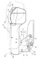
アームレスト装置40は、図2に示す如く、オペレータの肘を載置するためのアームレスト41と、該アームレスト41のスイベルシート31に対する前後方向及び上下方向の位置調整を可能とする位置調整機構51とを備え、アームレスト41は、該位置調整機構51を介してスイベルシート31の座部31aに支持されている。
アームレスト41は、図1及び図2に示す如く、直方体状に形成されたアーム本体42を備え、該アーム本体42の先端部には、種々の車体制御を行うための操作部43が配備されている。また、アーム本体42の上面は、クッション材42aによって覆われており、これによって、オペレータが肘をアーム本体42に載置した状態で長時間の作業を行った場合にも、該オペレータの疲労は軽減されるのである。
As shown in FIG. 2, the
As shown in FIGS. 1 and 2, the
操作部43の上面には、前記油圧昇降装置20を動作させて前記作業機を所定の高さ位置に設定するためのポジションレバー43aが操作部43の前後方向に摺動自在に配備されると共に、該ポジションレバー43aの摺動を規制して作業機の下限位置を保持するための下限規制ドラム43bが枢軸廻りに回転自在に配備されている。
また、図3に示す如く、操作部43のスイベルシート31側の側面には、トラクタ1の
走行時の変速操作を行うためのシフトアップボタン及びシフトダウンボタンからなる変速シフト操作部43cと、前記作業機を所定の上限位置と下限位置との間で昇降移動させるためのポンパスイッチ43dが配備されている。
On the upper surface of the
Further, as shown in FIG. 3, on the side surface of the
なお、変速シフト操作部43cは、トラクタ1の速度を8段階乃至16段階に変速させるものであるが、これ以外の段階に変速させるものであってももちろん構わない。
図2に示す如く、前記位置調整機構51は、スイベルシート31に支持された支持台52と、アーム本体42に連結された連結部材53と、該連結部材53を支持台52に連結する平行リンク手段54とを備えている。
図1、図4及び図5に示す如く、支持台52は、板金加工や金属板にプレス加工を施すことによって形成されており、スイベルシート31の座部31aの底面に沿って伸びる水平片55aと該座部31aの右側面に沿って伸びる起立片55bとから構成されるアングル状の支持部55と、該支持部55の起立片55bの後端部からスイベルシート31の背もたれ31bに向かって屈曲して伸びる伸長部56とから構成されており、支持部55の水平片55a及び起立片55bがスイベルシート31の座部31aの底面及び右側面にボルト締結等によってそれぞれ固定されている。
The shift
As shown in FIG. 2, the
As shown in FIGS. 1, 4 and 5, the
連結部材53は、図5または図6に示す如く、板金加工や金属板にプレス加工を施すことによって断面U字状に形成されており、一対の平板部57a、57bと、該一対の平板部57a、57bの上端部を連結する連結部58とから構成されており、該連結部58がアーム本体42の後部底面に形成された凹部42bに収容された状態でボルト締結等によって固定されることにより、該連結部材53はアームレスト41に固定されている。
平行リンク手段54は、図4〜図6に示す如く、金属板をプレス加工してなる断面U字状に形成された一対のリンク体59、60を備え、前側のリンク体59は、一方の端部が前記支持台52の支持部55の起立片55bに左右方向に伸びる枢支ピン61を介して揺動自在に枢支されており、他方の端部が連結部材53の一対の平板部57a、57bに挟み込まれた状態で該一対の平板部57a、57bに左右方向に伸びる枢支ピン62を介して揺動自在に枢支されている。
As shown in FIG. 5 or FIG. 6, the connecting
4 to 6, the parallel link means 54 includes a pair of
また、後側のリンク体60も同様に、一方の端部が前記支持台52の伸長部56の基端部に左右方向に伸びる枢支ピン63を介して揺動自在に枢支されており、他方の端部が連結部材53の一対の平板部57a、57bに挟み込まれた状態で該一対の平板部57a、57bに左右方向に伸びる枢支ピン64を介して揺動自在に枢支されている。
また、上記位置調整機構51は、平行リンク手段54の一対のリンク体59、60の揺動角を設定してアームレスト41を所定の上下位置及び前後位置に設定するための角度設定手段71を有したものとなっている。
Similarly, the
The
該角度設定手段71は、アームレスト41の位置設定状態と位置調整可能状態との切換操作を行うための切換操作ピン(切換操作部材)72と、該切換操作ピン72の移動を案内するガイド部73とから構成されている。
切換操作ピン72は、図6に示す如く、前記連結部材53の一対の平板部57a、57bを貫通して伸びるポール状を呈しており、その断面形状は、長方形の短辺を突円弧状に湾曲させた小判形状に形成されている。また、図5に示す如く、切換操作ピン72のスイベルシート31側の端部には、該切換操作ピン72のガイド部73からの抜け止めを施すため抜け止めピン72bが取り付けられており、スイベルシート31とは反対側の端部には、切換操作ピン72の長軸方向に伸びる操作レバー72aが突設されている。
The angle setting means 71 includes a switching operation pin (switching operation member) 72 for performing a switching operation between the position setting state and the position adjustable state of the armrest 41, and a
As shown in FIG. 6, the switching
ガイド部73は、図6に示す如く、前記連結部材53の一対の平板部57a、57bの内、前記スイベルシート31とは反対側に位置する一方の平板部57aに開設されたガイド溝74と、スイベルシート31側に位置する他方の平板部57bに開設された摺動溝75と、前記後側のリンク体60の一対の脚部60a、60bの内、連結部材53の一方の平板部57a側の脚部60aに開設された長孔76と、連結部材53の他方の平板部57b側の脚部60bに開設された挿通孔77とから構成されている。
また、ガイド部73は、図5に示す如く、連結部材53の一対の平板部57a、57bの間に後側のリンク体60を挟み込んだ状態で該リンク体60を一対の枢支ピン63、6
4によって枢支することにより、ガイド溝74、長孔76、挿通孔77及び摺動溝75が互いに連通され、これらガイド溝74、長孔76、挿通孔77及び摺動溝75を貫通して前記切換操作ピン72が配備されている。また、切換操作ピン72と前記枢支ピン64との間には、引張りコイルバネ78が架け渡されており、これによって切換操作ピン72は、前記枢支ピン64に近接する方向に付勢されている。
As shown in FIG. 6, the
Further, as shown in FIG. 5, the
4, the
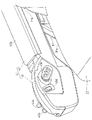
前記ガイド溝74は、図4に示す如く、前記枢支ピン64によって形成される枢軸を曲率中心として円弧状に伸びる長溝74aを有している。該長溝74aは、前記枢支ピン63の直下に位置する位置Aを始点として反時計回りに約30度〜40度の角度範囲で開設されており、これによって、長溝74aは、スイベルシート31に対して上下方向よりも前後方向に長く形成されることとなる。
従って、該長溝74a内にて前記切換操作ピン72を相対移動させることにより、アームレスト41は、スイベルシート31に対して後下方から前上方に向けて上下方向よりも前後方向に大きく移動することとなり、アームレスト41の位置調整に必要な該アームレスト41の移動空間が最小限に抑えられるのである。
As shown in FIG. 4, the
Accordingly, by relatively moving the switching
また、長溝74aの長手方向中途部の上側には、前記枢支ピン64によって形成される枢軸に向けて伸びる複数(本実施形態では4つ)の係合部74bが形成されている。
前記摺動溝75は、図6に示す如く、ガイド溝74の長溝74bと同様に、前記枢支ピン64によって形成される枢軸を曲率中心として該長溝74bと対向する位置に円弧状に形成されている。
これによって、前記切換操作ピン72は、前記平行リンク手段54の揺動に伴ってガイド溝74及び摺動溝75内を相対移動することとなり、該複数の係合部74bの内、所定の係合部74bに係合することにより、前記平行リンク手段54は支持台52に対して所定の揺動角に設定され、これによってアームレスト41は所定の位置設定状態に設定される。
Further, a plurality of (four in this embodiment) engaging
As shown in FIG. 6, the sliding
As a result, the switching
また、前記後側のリンク体60の一方の脚部60aに開設された長孔76は、前記切換操作ピン72のガイド溝74内での長溝74aから係合部74bに亘る移動を可能とすべく、前記引張りコイルバネ78による付勢方向に長く形成されている。
一方、前記後側のリンク体60の他方の脚部60bに開設された挿通孔77は、切換操作ピン72の断面形状よりも僅かに大きな小判形状に形成されており、これによって該切換操作ピン72の回り止めが施されているのである。
従って、前記操作レバー72aを前記付勢方向とは反対側に向けて押下した場合、切換操作ピン72の長孔76及びガイド溝74側の一方の端部は長孔76に沿って大きく上下動する一方、切換操作ピン72の挿通孔77及び摺動溝75側の他方の端部は僅かに上下動するのみであり、これによって、切換操作ピン72の前記一方の端部が前記他方の端部に対して揺動し、係合部74bから長溝74aに移動することとなる。
A
On the other hand, the
Therefore, when the
本発明の実施の形態は、以上の構成からなるもので、次に、アームレスト41の位置を調整する場合について図1、図4及び図5を参照して説明する。
図1に実線で示す如く、スイベルシート31に対して最も後下方の位置にてアームレスト41が位置設定状態に設定されている場合、前記角度設定手段71の切換操作ピン72は、ガイド部73のガイド溝74の係合部74bの内、最も前方に形成された係合部74bに係合しており、これによって、前記位置調整機構51の平行リンク手段54の一対のリンク体59、60は、支持台52に対して最も大きな揺動角に設定された状態で後方に傾いている。
The embodiment of the present invention has the above-described configuration. Next, the case where the position of the
As shown by the solid line in FIG. 1, when the
該位置設定状態からアームレスト41の位置調整を行う場合、先ず、図5中に矢印で示す如く、切換操作ピン72の操作レバー72aを該切換操作ピン72の前記付勢方向とは反対側に向けて押下する。
このとき、図5中に二点差線で示す如く、切換操作ピン72は、前記一方の端部が引張りコイルバネ78の付勢力に抗して他方の端部に対して揺動し、ガイド溝74内にて前記係合部74bを離脱して長溝74a内に移動する。これによって、平行リンク手段54の一対のリンク体59、60は揺動自在となり、これに伴って、アームレスト41は位置設
定状態から位置調整可能状態に切り換えられる。
When the position of the
At this time, as indicated by a two-dot chain line in FIG. 5, the switching
次に、操作レバー72aを押下した状態を保持し、切換操作ピン72の前記一方の端部をガイド溝74の長溝74a内に移動させた状態を保ちつつ、一対のリンク体59、60を揺動させてアームレスト41を前上方に向けて移動させる。
このとき、図4に示す切換操作ピン72はガイド溝74の長溝74a及び摺動溝75に案内されてこれら該長溝74a内及び摺動溝75内を相対移動し、これに伴って一対のリンク体59、60は支持台52に対して後方に傾いた姿勢から起ち上がり、これによってアームレスト41は、後下方から前上方に向けて斜前方に平行移動する。
Next, the state in which the
At this time, the switching
そして、アームレスト41を所望の前後位置及び上下位置に設定した後、切換操作ピン72の操作レバー72aの押下を解放することにより、該切換操作ピン72の前記一方の端部は、引っ張りコイルバネ78の付勢力に従ってガイド溝74の長溝74a内から前記前後位置及び上下位置に対応した係合部74bに移動し、該係合部74bに係合する。
これによって、例えば図1中に二点差線で示す如く、一対のリンク体59、60は所定の揺動角に保持され、アームレスト41は位置調整可能状態から所望の前後位置及び上下位置に設定された位置設定状態に再び設定されることとなる。
Then, after setting the
Accordingly, for example, as shown by a two-dot chain line in FIG. 1, the pair of
上記実施の形態によれば、切換操作ピン72を前記付勢方向とは反対側に向けて押下する容易な操作によって、アームレスト41は、位置設定状態から任意の前後位置及び上下位置に位置調整可能な位置調整可能状態に切り換えられる。また、該切換操作ピン72の押下を解除する容易な操作によって、切換操作ピン72は前記付勢力に従ってガイド部73のガイド溝74の係合部74bに係合し、これによってアームレスト41は、位置調整可能状態から再び位置設定状態に切り換えられるのである。
また、位置調整機構51の角度設定手段71は、上述の如く、ガイド溝74の長溝74aが上下方向よりも前後方向に長く形成されているため、アームレスト41は、切換操作ピン72のガイド溝74の長溝74a内の相対移動に伴って、上下方向よりも前後方向に大きい移動空間を平行移動するのである。
According to the above-described embodiment, the armrest 41 can be adjusted from the position setting state to the arbitrary front-rear position and the vertical position by an easy operation of pressing the
Further, the angle setting means 71 of the
従って、前記移動空間は最小限に抑えられることとなり、運転操縦装置30の各装置の配置の自由度が高まると共にキャビン8の小型化も図られるのである。
さらに、アームレスト41は、平行リンク手段54を介して前後方向及び上下方向に平行移動可能に支持台52に連結されているため、アームレスト41の位置調整に伴って該アームレスト41の支持台52及びスイベルシート31に対する取付姿勢が変更されることはない。
従って、オペレータは、位置調整可能状態に設定されたアームレスト41を所定の取付姿勢に保持する必要はなく、スイベルシート31に対する該アームレスト41の前後方向及び上下方向の位置調整のみを容易に行うことができるのである。
Therefore, the movement space is minimized, and the degree of freedom of arrangement of each device of the driving
Further, since the
Therefore, the operator does not need to hold the armrest 41 set in the position adjustable state in a predetermined mounting posture, and can easily perform only the position adjustment of the armrest 41 in the front-rear direction and the vertical direction with respect to the
また、上述の如き位置調整機構51及び角度設定手段71によれば、所定の位置設定状態に設定したアームレスト41を他の位置設定状態に変更した場合にも、切換操作ピン72を操作することにより、該アームレスト41を容易に前記所定の位置設定状態に再び設定することができるのである。
以上、本発明の実施形態を詳述したが、本発明は上記の実施の形態に限定されるものではない。
例えば切換操作ピン72は、前記後側のリンク体60の支持台52側の枢支ピン63に向けて付勢されていてもよく、この場合、ガイド部73のガイド溝74は、前記枢支ピン63によって形成される枢軸を曲率中心とする長溝74aと、該長溝74aの長手方向中途部の下側に形成された複数の係合部74bとによって構成されることとなる。
Further, according to the
As mentioned above, although embodiment of this invention was explained in full detail, this invention is not limited to said embodiment.
For example, the switching
また、ガイド部73のガイド溝74を支持台52に形成し、該ガイド部73及び該ガイド溝74に挿通された切換操作ピン72を備えた角度調整手段71を採用しても構わない。
また、切換操作ピン72の断面形状は、楕円形状、長方形状、多角形状等を採用しても良く、前記後側のリンク体60に形成された長孔76及び挿通孔77に挿通された状態で容易に回転しないものであれば、いかなる断面形状を採用しても構わない。
さらに、切換操作ピン72は、一対のリンク体59、60の何れかに挿通されていれば良いので、後側のリンク体60に代えて前側のリンク体59に対して前記角度設定手段71を設けることももちろん可能である。
Alternatively, the angle adjusting means 71 may be employed in which the
Moreover, the cross-sectional shape of the switching
Further, the switching
また、本発明にかかるアームレスト装置40をバックホーやTLB作業機等の他の作業車両に採用可能であることはもちろんである。これに伴って、本実施の形態においてはスイベルシート31の右側のみに採用したアームレスト装置40をスイベルシート31の左側若しくは両側に配備しても構わない。
Moreover, it is needless to say that the
1 トラクタ
8 キャビン
28 運転操作席
31 スイベルシート
40 アームレスト装置
41 アームレスト
42 アーム本体
43 操作部
51 位置調整機構
52 支持台
53 連結部材
54 平行リンク手段
59 リンク体
60 リンク体
71 角度設定手段
72 切換操作ピン
73 ガイド部
74 ガイド溝
75 摺動溝
76 長溝
77 挿通孔
78 引張りコイルバネ
DESCRIPTION OF
Claims (2)
前記位置調整機構(51)は、運転席(31)側方に取り付けられた支持台(52)と、前記アーム本体(42)に連結されていて左右一対の平板部(57a,57b)を有する連結部材(53)と、該連結部材(53)と支持台(52)とを連結する平行リンク手段(54)と、平行リンク手段(54)の前後一対のリンク体(59,60)の揺動角を設定する角度設定手段(71)とを有しており、
前記切換操作部材(72)は、前記平行リンク手段(54)の一方のリンク体(60)を貫通して設けられており、前記角度設定手段(71)は、前記連結部材(53)の左右平板部(57a,57b)に形成されて前記切換操作部材(72)の移動を案内するガイド溝(74)と摺動溝(75)とをそれぞれ備え、前記ガイド溝(74)には、前記切換操作部材(72)と係合して前記前後一方のリンク体(60)の揺動角度を設定するための係合部(74b)が複数形成されており、
前記切換操作部材(72)は、前記摺動溝(75)側に対して前記ガイド溝(74)側を揺動して係合部(74b)に係脱させるための操作レバー(72a)が設けられていることを特徴とするアームレスト装置。 An armrest (41) having an operating portion (43) and disposed on the side of the driver seat (31 ) and having an arm body (42) , and the armrest (41) with respect to the driver seat (31) And a position adjustment mechanism (51) that supports the position adjustment in the vertical direction and the vertical direction, and the position adjustment mechanism (51) has a switching operation for switching the armrest (41) between a position setting state and a position adjustable state. A member (72) is provided ;
The position adjusting mechanism (51) has a support base (52) attached to the side of the driver's seat (31) and a pair of left and right flat plates (57a, 57b) connected to the arm body (42). The connecting member (53), the parallel link means (54) for connecting the connecting member (53) and the support base (52), and the swinging of the pair of front and rear link bodies (59, 60) of the parallel link means (54). Angle setting means (71) for setting a moving angle,
The switching operation member (72) is provided so as to penetrate one link body (60) of the parallel link means (54), and the angle setting means (71) is provided on the left and right sides of the connecting member (53). Each of the guide grooves (74) includes a guide groove (74) and a slide groove (75) that are formed in the flat plate portions (57a, 57b) and guide the movement of the switching operation member (72). A plurality of engaging portions (74b) for engaging with the switching operation member (72) and setting the swing angle of the one of the front and rear link bodies (60) are formed,
The switching operation member (72) has an operation lever (72a) for swinging the guide groove (74) side with respect to the sliding groove (75) side to engage and disengage with the engaging portion (74b). An armrest device characterized by being provided .
Priority Applications (1)
| Application Number | Priority Date | Filing Date | Title |
|---|---|---|---|
| JP2004153584A JP4286183B2 (en) | 2004-05-24 | 2004-05-24 | Armrest device |
Applications Claiming Priority (1)
| Application Number | Priority Date | Filing Date | Title |
|---|---|---|---|
| JP2004153584A JP4286183B2 (en) | 2004-05-24 | 2004-05-24 | Armrest device |
Publications (2)
| Publication Number | Publication Date |
|---|---|
| JP2005335429A JP2005335429A (en) | 2005-12-08 |
| JP4286183B2 true JP4286183B2 (en) | 2009-06-24 |
Family
ID=35489484
Family Applications (1)
| Application Number | Title | Priority Date | Filing Date |
|---|---|---|---|
| JP2004153584A Expired - Lifetime JP4286183B2 (en) | 2004-05-24 | 2004-05-24 | Armrest device |
Country Status (1)
| Country | Link |
|---|---|
| JP (1) | JP4286183B2 (en) |
Cited By (3)
| Publication number | Priority date | Publication date | Assignee | Title |
|---|---|---|---|---|
| CN108784085A (en) * | 2012-09-20 | 2018-11-13 | 斯迪尔科斯公司 | Chair assembly and armrest assembly |
| CN109760557A (en) * | 2017-11-10 | 2019-05-17 | 格拉默公司 | Vehicle seat including regulating device |
| KR102294109B1 (en) * | 2020-12-21 | 2021-08-25 | 안국수 | Multi-joint driven console box for construction equipment |
Families Citing this family (17)
| Publication number | Priority date | Publication date | Assignee | Title |
|---|---|---|---|---|
| JP4882564B2 (en) * | 2006-07-14 | 2012-02-22 | 井関農機株式会社 | Working machine lifting operation device |
| JP5098290B2 (en) * | 2006-10-26 | 2012-12-12 | 井関農機株式会社 | Work vehicle |
| JP5289711B2 (en) * | 2007-01-23 | 2013-09-11 | 株式会社フジ医療器 | Massage chair |
| JP5279190B2 (en) * | 2007-01-31 | 2013-09-04 | 株式会社フジ医療器 | Massage chair |
| JP5248793B2 (en) * | 2007-03-17 | 2013-07-31 | 三菱農機株式会社 | Work vehicle |
| JP2008254534A (en) * | 2007-04-03 | 2008-10-23 | Yanmar Co Ltd | Working vehicle |
| JP5280819B2 (en) * | 2008-12-02 | 2013-09-04 | ヤンマー株式会社 | Armrest structure of work vehicle |
| KR101578788B1 (en) | 2008-12-02 | 2015-12-18 | 얀마 가부시키가이샤 | Armrest structure for working vehicle, structure for operating section for working vehicle, and armrest unit |
| JP2009234570A (en) * | 2009-05-29 | 2009-10-15 | Iseki & Co Ltd | Utility vehicle |
| US11304528B2 (en) | 2012-09-20 | 2022-04-19 | Steelcase Inc. | Chair assembly with upholstery covering |
| USD697726S1 (en) | 2012-09-20 | 2014-01-21 | Steelcase Inc. | Chair |
| KR101666715B1 (en) | 2014-02-19 | 2016-10-17 | 가부시끼 가이샤 구보다 | Armrest device |
| JP6162619B2 (en) * | 2014-02-19 | 2017-07-12 | 株式会社クボタ | Armrest |
| JP6946091B2 (en) * | 2017-07-18 | 2021-10-06 | 株式会社クボタ | Work machine |
| JP7171500B2 (en) * | 2018-06-25 | 2022-11-15 | 株式会社クボタ | work vehicle |
| JP7244252B2 (en) * | 2018-10-26 | 2023-03-22 | 株式会社小松製作所 | work vehicle |
| CN112959930B (en) * | 2021-04-07 | 2025-03-21 | 延锋汽车饰件系统武汉有限公司 | An automobile interior component |
-
2004
- 2004-05-24 JP JP2004153584A patent/JP4286183B2/en not_active Expired - Lifetime
Cited By (8)
| Publication number | Priority date | Publication date | Assignee | Title |
|---|---|---|---|---|
| CN108784085A (en) * | 2012-09-20 | 2018-11-13 | 斯迪尔科斯公司 | Chair assembly and armrest assembly |
| CN109760557A (en) * | 2017-11-10 | 2019-05-17 | 格拉默公司 | Vehicle seat including regulating device |
| EP3486114A1 (en) * | 2017-11-10 | 2019-05-22 | Grammer AG | Vehicle seat with adjustment aid |
| US10702069B2 (en) | 2017-11-10 | 2020-07-07 | Grammer Ag | Vehicle seat comprising an adjustment device |
| DE102017126429B4 (en) * | 2017-11-10 | 2021-03-18 | Grammer Aktiengesellschaft | Vehicle seat with an operating device and an adjusting device |
| CN109760557B (en) * | 2017-11-10 | 2021-11-19 | 格拉默公司 | Vehicle seat comprising an adjusting device |
| KR102294109B1 (en) * | 2020-12-21 | 2021-08-25 | 안국수 | Multi-joint driven console box for construction equipment |
| US12077080B2 (en) | 2020-12-21 | 2024-09-03 | Gugsoo An | Multi-joint driven console box for construction equipment |
Also Published As
| Publication number | Publication date |
|---|---|
| JP2005335429A (en) | 2005-12-08 |
Similar Documents
| Publication | Publication Date | Title |
|---|---|---|
| JP4286183B2 (en) | Armrest device | |
| US20100026026A1 (en) | Apparatus for adjusting height of console of construction machine | |
| US9534354B2 (en) | Construction machine | |
| KR101114734B1 (en) | Riding type rice transplanter | |
| EP1966027B1 (en) | Cab structure for a vehicle | |
| JP5016573B2 (en) | Loader working machine | |
| JPWO2017006592A1 (en) | Tractor | |
| JP3666678B2 (en) | Control box opening and closing device | |
| JP4429976B2 (en) | Loader operating device | |
| JP4056850B2 (en) | Work vehicle seat equipment | |
| JP4469186B2 (en) | Work machine | |
| JP2012017589A (en) | Control device of front loader | |
| JP2019138005A (en) | Work vehicle | |
| JP6566837B2 (en) | Front loader with work vehicle and stand | |
| JPH1136368A (en) | Operation lever device of construction machine | |
| EP4534760A1 (en) | Front loader and working vehicle | |
| JP4447516B2 (en) | Tractor | |
| US20250034840A1 (en) | Cab and work machine | |
| JP2007092284A (en) | Work vehicle | |
| JP2007255150A (en) | Work vehicle | |
| JP2693285B2 (en) | Control lever device | |
| JP2014227061A (en) | Working vehicle | |
| JP3928911B2 (en) | Operation vehicle position adjustment device for work vehicle | |
| CN120530247A (en) | Cockpit structure for construction machinery | |
| JP2014210519A (en) | Seat height adjusting device |
Legal Events
| Date | Code | Title | Description |
|---|---|---|---|
| A621 | Written request for application examination |
Free format text: JAPANESE INTERMEDIATE CODE: A621 Effective date: 20060926 |
|
| A977 | Report on retrieval |
Free format text: JAPANESE INTERMEDIATE CODE: A971007 Effective date: 20081205 |
|
| A131 | Notification of reasons for refusal |
Free format text: JAPANESE INTERMEDIATE CODE: A131 Effective date: 20081216 |
|
| A521 | Written amendment |
Free format text: JAPANESE INTERMEDIATE CODE: A523 Effective date: 20090212 |
|
| TRDD | Decision of grant or rejection written | ||
| A01 | Written decision to grant a patent or to grant a registration (utility model) |
Free format text: JAPANESE INTERMEDIATE CODE: A01 Effective date: 20090324 |
|
| A01 | Written decision to grant a patent or to grant a registration (utility model) |
Free format text: JAPANESE INTERMEDIATE CODE: A01 |
|
| A61 | First payment of annual fees (during grant procedure) |
Free format text: JAPANESE INTERMEDIATE CODE: A61 Effective date: 20090324 |
|
| FPAY | Renewal fee payment (event date is renewal date of database) |
Free format text: PAYMENT UNTIL: 20120403 Year of fee payment: 3 |
|
| R150 | Certificate of patent or registration of utility model |
Ref document number: 4286183 Country of ref document: JP Free format text: JAPANESE INTERMEDIATE CODE: R150 Free format text: JAPANESE INTERMEDIATE CODE: R150 |
|
| FPAY | Renewal fee payment (event date is renewal date of database) |
Free format text: PAYMENT UNTIL: 20120403 Year of fee payment: 3 |
|
| FPAY | Renewal fee payment (event date is renewal date of database) |
Free format text: PAYMENT UNTIL: 20130403 Year of fee payment: 4 |
|
| FPAY | Renewal fee payment (event date is renewal date of database) |
Free format text: PAYMENT UNTIL: 20130403 Year of fee payment: 4 |
|
| FPAY | Renewal fee payment (event date is renewal date of database) |
Free format text: PAYMENT UNTIL: 20140403 Year of fee payment: 5 |