JP4273636B2 - Information recording apparatus and method, and information recording system - Google Patents
Information recording apparatus and method, and information recording system Download PDFInfo
- Publication number
- JP4273636B2 JP4273636B2 JP2000200369A JP2000200369A JP4273636B2 JP 4273636 B2 JP4273636 B2 JP 4273636B2 JP 2000200369 A JP2000200369 A JP 2000200369A JP 2000200369 A JP2000200369 A JP 2000200369A JP 4273636 B2 JP4273636 B2 JP 4273636B2
- Authority
- JP
- Japan
- Prior art keywords
- metadata
- data
- information
- cassette
- memory tag
- Prior art date
- Legal status (The legal status is an assumption and is not a legal conclusion. Google has not performed a legal analysis and makes no representation as to the accuracy of the status listed.)
- Expired - Lifetime
Links
- 238000000034 method Methods 0.000 title claims description 45
- 239000000463 material Substances 0.000 claims description 60
- 230000005672 electromagnetic field Effects 0.000 claims description 26
- 230000004044 response Effects 0.000 claims description 25
- 238000003860 storage Methods 0.000 claims description 24
- 238000000605 extraction Methods 0.000 claims description 9
- 238000010586 diagram Methods 0.000 description 61
- 238000012545 processing Methods 0.000 description 34
- 239000004065 semiconductor Substances 0.000 description 34
- 230000005540 biological transmission Effects 0.000 description 32
- 230000006870 function Effects 0.000 description 26
- 230000005236 sound signal Effects 0.000 description 23
- 230000008569 process Effects 0.000 description 19
- 238000004519 manufacturing process Methods 0.000 description 16
- 230000008859 change Effects 0.000 description 9
- 230000006835 compression Effects 0.000 description 9
- 238000007906 compression Methods 0.000 description 9
- 238000012937 correction Methods 0.000 description 9
- 239000000284 extract Substances 0.000 description 7
- 238000003384 imaging method Methods 0.000 description 7
- 230000006698 induction Effects 0.000 description 6
- 238000004804 winding Methods 0.000 description 6
- 238000006243 chemical reaction Methods 0.000 description 5
- 238000012790 confirmation Methods 0.000 description 4
- 230000008878 coupling Effects 0.000 description 4
- 238000010168 coupling process Methods 0.000 description 4
- 238000005859 coupling reaction Methods 0.000 description 4
- 230000006837 decompression Effects 0.000 description 4
- 238000001514 detection method Methods 0.000 description 4
- 238000012423 maintenance Methods 0.000 description 4
- 230000007246 mechanism Effects 0.000 description 4
- 238000012544 monitoring process Methods 0.000 description 4
- 230000002265 prevention Effects 0.000 description 4
- 239000002131 composite material Substances 0.000 description 3
- 238000003780 insertion Methods 0.000 description 3
- 230000037431 insertion Effects 0.000 description 3
- 230000008520 organization Effects 0.000 description 3
- 239000003990 capacitor Substances 0.000 description 2
- 238000004891 communication Methods 0.000 description 2
- 230000001419 dependent effect Effects 0.000 description 2
- 230000006866 deterioration Effects 0.000 description 2
- 238000005516 engineering process Methods 0.000 description 2
- 210000003127 knee Anatomy 0.000 description 2
- 230000000750 progressive effect Effects 0.000 description 2
- 230000009471 action Effects 0.000 description 1
- 230000003321 amplification Effects 0.000 description 1
- 238000004458 analytical method Methods 0.000 description 1
- 230000000694 effects Effects 0.000 description 1
- 230000004907 flux Effects 0.000 description 1
- 230000001939 inductive effect Effects 0.000 description 1
- 239000004973 liquid crystal related substance Substances 0.000 description 1
- 230000000116 mitigating effect Effects 0.000 description 1
- 238000003199 nucleic acid amplification method Methods 0.000 description 1
- 230000000149 penetrating effect Effects 0.000 description 1
- 238000002360 preparation method Methods 0.000 description 1
- 238000007639 printing Methods 0.000 description 1
- 230000006641 stabilisation Effects 0.000 description 1
- 238000011105 stabilization Methods 0.000 description 1
- 230000000087 stabilizing effect Effects 0.000 description 1
Images


Classifications
-
- H—ELECTRICITY
- H04—ELECTRIC COMMUNICATION TECHNIQUE
- H04N—PICTORIAL COMMUNICATION, e.g. TELEVISION
- H04N9/00—Details of colour television systems
- H04N9/79—Processing of colour television signals in connection with recording
- H04N9/80—Transformation of the television signal for recording, e.g. modulation, frequency changing; Inverse transformation for playback
- H04N9/804—Transformation of the television signal for recording, e.g. modulation, frequency changing; Inverse transformation for playback involving pulse code modulation of the colour picture signal components
- H04N9/8042—Transformation of the television signal for recording, e.g. modulation, frequency changing; Inverse transformation for playback involving pulse code modulation of the colour picture signal components involving data reduction
-
- G—PHYSICS
- G11—INFORMATION STORAGE
- G11B—INFORMATION STORAGE BASED ON RELATIVE MOVEMENT BETWEEN RECORD CARRIER AND TRANSDUCER
- G11B27/00—Editing; Indexing; Addressing; Timing or synchronising; Monitoring; Measuring tape travel
- G11B27/002—Programmed access in sequence to a plurality of record carriers or indexed parts, e.g. tracks, thereof, e.g. for editing
-
- G—PHYSICS
- G11—INFORMATION STORAGE
- G11B—INFORMATION STORAGE BASED ON RELATIVE MOVEMENT BETWEEN RECORD CARRIER AND TRANSDUCER
- G11B27/00—Editing; Indexing; Addressing; Timing or synchronising; Monitoring; Measuring tape travel
- G11B27/02—Editing, e.g. varying the order of information signals recorded on, or reproduced from, record carriers
- G11B27/031—Electronic editing of digitised analogue information signals, e.g. audio or video signals
- G11B27/032—Electronic editing of digitised analogue information signals, e.g. audio or video signals on tapes
-
- G—PHYSICS
- G11—INFORMATION STORAGE
- G11B—INFORMATION STORAGE BASED ON RELATIVE MOVEMENT BETWEEN RECORD CARRIER AND TRANSDUCER
- G11B27/00—Editing; Indexing; Addressing; Timing or synchronising; Monitoring; Measuring tape travel
- G11B27/02—Editing, e.g. varying the order of information signals recorded on, or reproduced from, record carriers
- G11B27/031—Electronic editing of digitised analogue information signals, e.g. audio or video signals
- G11B27/034—Electronic editing of digitised analogue information signals, e.g. audio or video signals on discs
-
- G—PHYSICS
- G11—INFORMATION STORAGE
- G11B—INFORMATION STORAGE BASED ON RELATIVE MOVEMENT BETWEEN RECORD CARRIER AND TRANSDUCER
- G11B27/00—Editing; Indexing; Addressing; Timing or synchronising; Monitoring; Measuring tape travel
- G11B27/10—Indexing; Addressing; Timing or synchronising; Measuring tape travel
- G11B27/102—Programmed access in sequence to addressed parts of tracks of operating record carriers
- G11B27/107—Programmed access in sequence to addressed parts of tracks of operating record carriers of operating tapes
-
- G—PHYSICS
- G11—INFORMATION STORAGE
- G11B—INFORMATION STORAGE BASED ON RELATIVE MOVEMENT BETWEEN RECORD CARRIER AND TRANSDUCER
- G11B27/00—Editing; Indexing; Addressing; Timing or synchronising; Monitoring; Measuring tape travel
- G11B27/10—Indexing; Addressing; Timing or synchronising; Measuring tape travel
- G11B27/11—Indexing; Addressing; Timing or synchronising; Measuring tape travel by using information not detectable on the record carrier
-
- G—PHYSICS
- G11—INFORMATION STORAGE
- G11B—INFORMATION STORAGE BASED ON RELATIVE MOVEMENT BETWEEN RECORD CARRIER AND TRANSDUCER
- G11B27/00—Editing; Indexing; Addressing; Timing or synchronising; Monitoring; Measuring tape travel
- G11B27/10—Indexing; Addressing; Timing or synchronising; Measuring tape travel
- G11B27/19—Indexing; Addressing; Timing or synchronising; Measuring tape travel by using information detectable on the record carrier
- G11B27/28—Indexing; Addressing; Timing or synchronising; Measuring tape travel by using information detectable on the record carrier by using information signals recorded by the same method as the main recording
- G11B27/30—Indexing; Addressing; Timing or synchronising; Measuring tape travel by using information detectable on the record carrier by using information signals recorded by the same method as the main recording on the same track as the main recording
- G11B27/3027—Indexing; Addressing; Timing or synchronising; Measuring tape travel by using information detectable on the record carrier by using information signals recorded by the same method as the main recording on the same track as the main recording used signal is digitally coded
- G11B27/3036—Time code signal
- G11B27/3054—Vertical Interval Time code [VITC]
-
- G—PHYSICS
- G11—INFORMATION STORAGE
- G11B—INFORMATION STORAGE BASED ON RELATIVE MOVEMENT BETWEEN RECORD CARRIER AND TRANSDUCER
- G11B27/00—Editing; Indexing; Addressing; Timing or synchronising; Monitoring; Measuring tape travel
- G11B27/10—Indexing; Addressing; Timing or synchronising; Measuring tape travel
- G11B27/34—Indicating arrangements
-
- G—PHYSICS
- G11—INFORMATION STORAGE
- G11B—INFORMATION STORAGE BASED ON RELATIVE MOVEMENT BETWEEN RECORD CARRIER AND TRANSDUCER
- G11B27/00—Editing; Indexing; Addressing; Timing or synchronising; Monitoring; Measuring tape travel
- G11B27/36—Monitoring, i.e. supervising the progress of recording or reproducing
-
- G—PHYSICS
- G11—INFORMATION STORAGE
- G11B—INFORMATION STORAGE BASED ON RELATIVE MOVEMENT BETWEEN RECORD CARRIER AND TRANSDUCER
- G11B15/00—Driving, starting or stopping record carriers of filamentary or web form; Driving both such record carriers and heads; Guiding such record carriers or containers therefor; Control thereof; Control of operating function
- G11B15/02—Control of operating function, e.g. switching from recording to reproducing
- G11B15/05—Control of operating function, e.g. switching from recording to reproducing by sensing features present on or derived from record carrier or container
- G11B15/06—Control of operating function, e.g. switching from recording to reproducing by sensing features present on or derived from record carrier or container by sensing auxiliary features on record carriers or containers, e.g. to stop machine near the end of a tape
- G11B15/07—Control of operating function, e.g. switching from recording to reproducing by sensing features present on or derived from record carrier or container by sensing auxiliary features on record carriers or containers, e.g. to stop machine near the end of a tape on containers
-
- G—PHYSICS
- G11—INFORMATION STORAGE
- G11B—INFORMATION STORAGE BASED ON RELATIVE MOVEMENT BETWEEN RECORD CARRIER AND TRANSDUCER
- G11B2220/00—Record carriers by type
- G11B2220/17—Card-like record carriers
-
- G—PHYSICS
- G11—INFORMATION STORAGE
- G11B—INFORMATION STORAGE BASED ON RELATIVE MOVEMENT BETWEEN RECORD CARRIER AND TRANSDUCER
- G11B2220/00—Record carriers by type
- G11B2220/40—Combinations of multiple record carriers
- G11B2220/41—Flat as opposed to hierarchical combination, e.g. library of tapes or discs, CD changer, or groups of record carriers that together store one title
-
- G—PHYSICS
- G11—INFORMATION STORAGE
- G11B—INFORMATION STORAGE BASED ON RELATIVE MOVEMENT BETWEEN RECORD CARRIER AND TRANSDUCER
- G11B2220/00—Record carriers by type
- G11B2220/60—Solid state media
- G11B2220/65—Solid state media wherein solid state memory is used for storing indexing information or metadata
- G11B2220/652—Solid state media wherein solid state memory is used for storing indexing information or metadata said memory being attached to the recording medium
- G11B2220/655—Memory in cassette [MIC]
-
- G—PHYSICS
- G11—INFORMATION STORAGE
- G11B—INFORMATION STORAGE BASED ON RELATIVE MOVEMENT BETWEEN RECORD CARRIER AND TRANSDUCER
- G11B2220/00—Record carriers by type
- G11B2220/90—Tape-like record carriers
-
- G—PHYSICS
- G11—INFORMATION STORAGE
- G11B—INFORMATION STORAGE BASED ON RELATIVE MOVEMENT BETWEEN RECORD CARRIER AND TRANSDUCER
- G11B23/00—Record carriers not specific to the method of recording or reproducing; Accessories, e.g. containers, specially adapted for co-operation with the recording or reproducing apparatus ; Intermediate mediums; Apparatus or processes specially adapted for their manufacture
- G11B23/02—Containers; Storing means both adapted to cooperate with the recording or reproducing means
- G11B23/04—Magazines; Cassettes for webs or filaments
- G11B23/08—Magazines; Cassettes for webs or filaments for housing webs or filaments having two distinct ends
- G11B23/087—Magazines; Cassettes for webs or filaments for housing webs or filaments having two distinct ends using two different reels or cores
- G11B23/08707—Details
- G11B23/08714—Auxiliary features
-
- G—PHYSICS
- G11—INFORMATION STORAGE
- G11B—INFORMATION STORAGE BASED ON RELATIVE MOVEMENT BETWEEN RECORD CARRIER AND TRANSDUCER
- G11B5/00—Recording by magnetisation or demagnetisation of a record carrier; Reproducing by magnetic means; Record carriers therefor
- G11B5/008—Recording on, or reproducing or erasing from, magnetic tapes, sheets, e.g. cards, or wires
- G11B5/00813—Recording on, or reproducing or erasing from, magnetic tapes, sheets, e.g. cards, or wires magnetic tapes
- G11B5/00847—Recording on, or reproducing or erasing from, magnetic tapes, sheets, e.g. cards, or wires magnetic tapes on transverse tracks
- G11B5/0086—Recording on, or reproducing or erasing from, magnetic tapes, sheets, e.g. cards, or wires magnetic tapes on transverse tracks using cyclically driven heads providing segmented tracks
-
- H—ELECTRICITY
- H04—ELECTRIC COMMUNICATION TECHNIQUE
- H04N—PICTORIAL COMMUNICATION, e.g. TELEVISION
- H04N5/00—Details of television systems
- H04N5/76—Television signal recording
- H04N5/765—Interface circuits between an apparatus for recording and another apparatus
-
- H—ELECTRICITY
- H04—ELECTRIC COMMUNICATION TECHNIQUE
- H04N—PICTORIAL COMMUNICATION, e.g. TELEVISION
- H04N5/00—Details of television systems
- H04N5/76—Television signal recording
- H04N5/765—Interface circuits between an apparatus for recording and another apparatus
- H04N5/77—Interface circuits between an apparatus for recording and another apparatus between a recording apparatus and a television camera
- H04N5/772—Interface circuits between an apparatus for recording and another apparatus between a recording apparatus and a television camera the recording apparatus and the television camera being placed in the same enclosure
-
- H—ELECTRICITY
- H04—ELECTRIC COMMUNICATION TECHNIQUE
- H04N—PICTORIAL COMMUNICATION, e.g. TELEVISION
- H04N5/00—Details of television systems
- H04N5/76—Television signal recording
- H04N5/765—Interface circuits between an apparatus for recording and another apparatus
- H04N5/775—Interface circuits between an apparatus for recording and another apparatus between a recording apparatus and a television receiver
Landscapes
- Engineering & Computer Science (AREA)
- Multimedia (AREA)
- Signal Processing (AREA)
- Management Or Editing Of Information On Record Carriers (AREA)
- Indexing, Searching, Synchronizing, And The Amount Of Synchronization Travel Of Record Carriers (AREA)
- Signal Processing For Digital Recording And Reproducing (AREA)
- Television Signal Processing For Recording (AREA)
Description
【0001】
【発明の属する技術分野】
本発明は、各種のリムーバブル記録メディアに記録される情報素材に関連したメタデータの記録を行う情報記録装置及び方法、情報記録再生システムに関する。
【0002】
【従来の技術】
従来より、ディジタル映像信号の規格の一つとして、ISO(Internatioal Organization for Standardization)/SMPTE(Society of Motion Picture and Television Enginieers)に規定された規格がある。特に、SMPTE 298M,335Mには、ディジタル映像信号などの素材データの属性、格納場所、サイズなどを表すメタデータについて定義されており、そのメタデータディクショナリ(Metadata dictionary)を用いてメタデータを集中的に管理することが可能となさている。当該メタデータディクショナリには、例えば、タイトル、スタッフ名、撮影場所など、数百項目が定義されている。
【0003】
上記メタデータは、映像音声等の素材の素性を知る上で重宝する情報であり、上述のようにISO/SMPTEで一意的に定義されているため互換性が極めて高く、データベース管理や他社間での素材交換の自動化に大きく寄与することができると考えられている。
【0004】
【発明が解決しようとする課題】
しかしながら、上記メタデータは、基本的に映像、音声信号などの素材に重畳されているものであるため、それら映像、音声素材が例えば記録メディアに記録されているような場合には、その記録メディアを再生しなければ上記メタデータも読み取ることが出来ない。
【0005】
その一方で、上記記録メディアを再生して実際に映像を見たり音声を聞いたりしてその素材に関する情報を作成するのであれば、上記素材に重畳されているメタデータに頼る必然性も薄れてしまい、そのため、現状では、メタデータはその存在価値を発揮していないと言える。
【0006】
そこで、本発明はこのような状況に鑑みてなされたものであり、実際に記録メディアに記録されている素材を再生することなしに、その記録メディアに記録されている素材に関するメタデータを得られるようにし、検索や確認等にメタデータを役立てることを可能とする、情報記録装置及び方法、情報記録システムを提供することを目的とする。
【0007】
【課題を解決するための手段】
本発明の情報記録装置は、入れ換え可能な記録媒体へ記録される素材信号に埋め込まれている所定規格のメタデータを抽出する抽出手段と、上記入れ換え可能な記録媒体へ記録される素材信号以外の情報から、上記素材信号に関連するメタデータを生成するメタデータ生成手段と、上記抽出したメタデータ及び上記生成したメタデータを保持する保持手段と、上記保持されているメタデータを所定のデータフォーマットに整理する整理手段と、電磁界に感応して作動し、当該電磁界を介して非接触により外部と情報送受をなすと共に上記入れ換え可能な記録媒体に添設或いは組み込まれる非接触型情報格納手段への情報書き込み読み出しを行う書込読出手段とを有し、上記メタデータは、少なくともUMID( Unique Material IDentifier )データを含み、上記所定のデータフォーマットに整理された上記メタデータを上記書込読出手段により上記非接触型情報格納手段に書き込み、上記書込読出手段により読み出されたメタデータを外部に出力する場合には、読み出されたUMIDデータからSMPTE( Society of Motion Picture and Television Enginieers )に規定される正規のUMIDデータに変換することにより、上述した課題を解決する。
【0008】
また、本発明の情報記録方法は、入れ換え可能な記録媒体へ記録される素材信号に埋め込まれている所定規格のメタデータを抽出するステップと、上記入れ換え可能な記録媒体へ記録される素材信号以外の情報から、上記素材信号に関連するメタデータを生成するステップと、上記抽出したメタデータ及び上記生成したメタデータを保持手段に保持するステップと、上記保持されているメタデータを所定のデータフォーマットに整理するステップと、電磁界に感応して作動し、当該電磁界を介して非接触により外部と情報送受をなすと共に上記入れ換え可能な記録媒体に添設或いは組み込まれる非接触型情報格納手段への情報書き込み読み出しを行うステップとを有し、上記メタデータは、少なくともUMID( Unique Material IDentifier )データを含み、上記所定のデータフォーマットに整理された上記メタデータを上記書込読出ステップにより上記非接触型情報格納手段に書き込み、上記書込読出ステップにより読み出されたメタデータを外部に出力する場合には、読み出されたUMIDデータからSMPTE( Society of Motion Picture and Television Enginieers )に規定される正規のUMIDデータに変換することにより、上述した課題を解決する。
【0011】
次に、本発明の情報記録システムは、電磁界に感応して作動し、当該電磁界を介して非接触により外部と情報送受をなすと共に入れ換え可能な記録媒体に添設或いは組み込まれる非接触型情報格納手段への情報書き込み読み出しを行う書込読出手段と、上記記録媒体へ記録される素材信号から抽出した所定規格のメタデータ、或いは、上記記録媒体へ記録される素材信号以外の情報から生成したメタデータを、保持手段に保持し、該保持されているメタデータを所定のデータフォーマットに整理して、上記書込読出手段により上記非接触型情報格納手段に書き込む情報記録装置と、複数の記録媒体に添設或いは組み込まれた非接触型情報格納手段から読み出された上記メタデータを蓄積するメタデータ蓄積装置とを有し、上記メタデータは、少なくともUMID( Unique Material IDentifier )データを含み、上記所定のデータフォーマットに整理された上記メタデータを上記書込読出手段により上記非接触型情報格納手段に書き込み、上記書込読出手段により読み出されたメタデータを外部に出力する場合には、読み出されたUMIDデータからSMPTE( Society of Motion Picture and Television Enginieers )に規定される正規のUMIDデータに変換することにより、上述した課題を解決する。
【0013】
【発明の実施の形態】
本発明の好ましい実施の形態について、図面を参照しながら説明する。
【0014】
図1には、本発明の第1の実施の形態として、高精細度ディジタル映像信号を記録再生するビデオテープレコーダ(以下、VTRとする)の概略構成を示す。
【0015】
ビデオ入力端子1には、例えばビデオカメラ等からSDI(Serial Digital data Interface) ANC(Ancillary)データパケットの形態で供給された映像信号(例えば1080/60インターレースの映像信号)が入力する。この映像信号は、入力アンプ2により増幅され、SDI ANC抽出部(Extract Integrated Circuit)3に入力する。当該SDI ANC抽出部3より出力された本線の映像信号は、ビデオ圧縮部4に送られる。なお、SDI ANCデータパケットについての説明は後述する。
【0016】
当該ビデオ圧縮部4では、所定の圧縮符号化方式により、上記映像信号を約1/7の情報量に圧縮する。このビデオ圧縮部4にて圧縮された映像信号は、ECC(Error Correcting Code)エンコーダ5に送られる。
【0017】
ECCエンコーダ5は、上記圧縮された映像信号にエラー訂正符号を付加する。このECCエンコーダ5からの出力は、記録のための変調処理やゲイン制御等を行う記録信号処理部6を介し、さらに記録アンプ7にて増幅された後、回転ドラム25の円周上に設けられた記録ヘッド8に送られる。
【0018】
回転ドラム25には、図示しないテープローディング機構によってビデオカセット31の筐体(以下、ビデオカセットを単にカセットと呼び、当該カセットの筐体をカセットハーフと呼ぶ)内から引き出された磁気テープ30が、既定の巻き付け角度で且つ一定のテンションにて巻き付けられ、さらに、当該回転ドラム25は、図示しないドラム回転モータにより既定の速度で回転駆動される。また、上記磁気テープ30は、図示しないリールモータによって供給リール33及び巻き取りリール34が回転駆動されると共に、図示しないキャプスタンモータにより既定の速度で走行するようになされている。この状態で、記録ヘッド8は、いわゆるヘリカルスキャン(斜め走査)により磁気テープ30上に信号を記録する。
【0019】
一方、磁気テープ30上に記録された信号を再生する場合は、上述同様に磁気テープ30が回転ドラム25に既定の巻き付け角度で且つ一定のテンションにて巻き付けられ、当該回転ドラム25が既定の速度で回転駆動されると共に上記磁気テープ30が既定の速度で走行するようになされた状態で、上記回転ドラム25の円周上に設けられた再生ヘッド10が、いわゆるヘリカルスキャンにより当該磁気テープ30から信号を読み取る。
【0020】
この再生ヘッド10にて磁気テープ30から読み取られた信号は、再生アンプ11にて増幅された後、再生イコライザ部12により波形等化及び復調等がなされ、ECCデコーダ13に送られる。
【0021】
ECCデコーダ13は、上記再生イコライザ部12からの信号に付加されているエラー訂正符号を用いてエラー訂正処理を行い、そのエラー訂正処理後の信号(圧縮符号化されている映像信号)をビデオ伸張部14に送る。
【0022】
ビデオ伸張部14では、上記ビデオ圧縮部4での圧縮符号化方式に対応する伸張復号方式により、上記圧縮符号化されている映像信号を、元の映像信号(例えば1080/60インターレースの映像信号)に伸張復号する。この伸張復号後の映像信号は、後述するSDI ANC付加部15に送られる。
【0023】
当該SDI ANC付加部15によりSDIのシリアルデータとなされた映像信号は、出力アンプ16にて増幅された後、ビデオ出力端子17から出力される。
【0024】
なお、この図1において、音声信号の処理系については図示していないが、上記映像信号と時分割にて処理され、回転ドラム25上の記録ヘッド8により磁気テープ30上に記録され、また、再生ヘッド10により磁気テープ30から読み取られる。
【0025】
また、本実施の形態のカセット31のカセットハーフには、例えばテープに記録された内容のタイトルなどが手書き或いはプリント等により書き込まれるラベル32が貼り付けられている。図1では図示を簡略化しているが、当該ラベル32には、例えばEEPROM(Electically Erasable and Programmable ROM)のような記録保持動作が不要で書き換え可能な半導体メモリや電源整流安定化処理、変復調処理、通信解析処理などの各処理部を含むICチップ35と、電磁的に電源の供給及び信号の送受信を行うためのコイルアンテナ36などを内蔵した非接触型のメモリタグ37が設けられている。
【0026】
すなわち当該非接触型メモリタグ37は、専用の書き込み読み出し装置であるリーダライタ部26に設けられているコイルアンテナ24と当該タグ37に内蔵されているコイルアンテナ36との間の電磁結合によりエネルギを得る機能と、書込コマンドとデータを受け取り、当該書込コマンドに応じて上記ICチップ35内の半導体メモリにデータを書き込む機能と、読出コマンドに応じて上記半導体メモリからデータを読み出し、その読み出されたデータを上記電磁結合により返信する機能とを少なくとも有するものである。
【0027】
図1の例の場合、リーダライタ26は、VTRに内蔵され、主要な構成要素として、上記ラベル32の非接触型メモリタグ37内のコイルアンテナ36との間で電磁結合を行うためのコイルアンテナ24と、上記メモリタグ37との間でコマンドの送信やデータの送受信を行うための専用のインターフェイス部23とを有している。当該リーダライタ26のインターフェイス部23は、コイルアンテナ24と協調してメモリタグ37への電力供給を行うと共に、メモリタグ37へのデータ書き込み時にはCPU21から供給される上記書込コマンドと書込データを変調して上記メモリタグ37に送信し、一方で、メモリタグ37からのデータ読出時にはCPU21から供給される上記読出コマンドを変調して上記メモリタグ37に送信し、その読出コマンドに応じて上記メモリタグ37から読み出されて返信されてきたデータを復調してCPU21に転送する。なお、上記非接触型メモリタグ37とリーダライタ26の詳細については後述する。
【0028】
ここで、当該第1の実施の形態のビデオテープレコーダは、上記磁気テープ30に記録される映像信号(或いは磁気テープ30に記録されている映像信号)についての属性や内容を表す情報、格納場所、サイズなどの映像信号に関連する、例えばSMPTE298M、335Mで定義されたメタデータを、映像信号と共に記録/再生可能となされている。なお、SMPTE298M、335Mで定義されたメタデータの詳細については後述する。
【0029】
例えば、ビデオ入力端子1に供給される入力映像信号にメタデータが重畳されてきた場合、これらメタデータは、図2或いは図3に示すようなSDI ANCパケットとして重畳されてくることになる。なお、図2は、コンポーネントANCデータパケットのフォーマットを示し、図3は、コンポジットANCデータパケットのフォーマットを示している。図2に示すコンポーネントANCデータパケットは、ANCデータパケットの始まりを示す3ワード分のANCデータフラグ(ADF)と、使用されるデータフォーマットがデータブロック番号(DBN)とデータカウント(DC)が続くフォーマットとなるタイプ1か或いはセカンダリデータID(SDID)とデータカウント(DC)が続くフォーマットとなるタイプ2かを定義するデータID(DID)と、上記セカンダリデータID(SDID)又はデータブロック番号(DBN)と、データカウント(DC)と、最大255ワードのユーザデータワード(UDW)と、チェックサム(C)とからなる。また、図3に示すコンポジットANCデータパケットは、1ワード分のANCデータフラグ(ADF)と、上記データID(DID)と、上記セカンダリデータID(SDID)又はデータブロック番号(DBN)と、データカウント(DC)と、ユーザデータワード(UDW)と、チェックサム(C)とからなる。
【0030】
これらのANCデータパケットにおいて、上記メタデータは、ユーザデータワード(UDW)に記述される。なお、SMPTE298M、335Mにて定義されているため、ここではその詳細な説明を省略するが、当該SMPTE298M、335Mにて定義されているメタデータは、例えば図4〜図6に示すようなものを挙げることができる。なおこれら図4〜図6に示すメタデータは、SMPTE298M、335Mで定義されているものの一部である。当該SMPTE298M、335Mのメタデータは、図4〜図6に示したように、大別して、キー(Key)としてのSMTPEラベル(label)と、データの長さを表すレングス(Length)と、内容を表すバリュー(Value)とからなるKLV方式の値として定義されている。これらメタデータは、映像音声素材に関連する様々な情報からなり、その中には、例えばタイトルや、タイトルの種類、主題(メインタイトル)、副題、その他、シリーズNo、エピソードNo、シーンNo、テイクNo、ビデオソース機材など、後述する編集時に使用される各種のデータも含まれている。
【0031】
図1に説明を戻し、図1のSDI ANC抽出部3では、上記図2や図3に示したようなANCデータパケットのユーザデータワード(UDW)から上記メタデータを抽出する。当該SDI ANC抽出部3にて抽出されたメタデータは、CPU(中央処理ユニット)21に送られ、さらに当該CPU21の制御の元でRAM22に蓄えられる。
【0032】
また例えば、外部入力端子から得られた情報や、付属する各種の機器、機材などから得られた情報、当該VTRの機種名、シリアル番号などの機器に関連する情報、基本的にCPU21が生成する現在日時などの情報、当該VTRのフロントパネルなどに設けられている操作盤28から操作者により入力された情報なども、必要に応じて加工や変換、組み合わせ等されて、上記メタデータとして同様にRAM22に書き込まれる。他に例えば、RS−422のフォーマットの情報として、メタデータが直接RS−422端子27から供給された場合は、そのメタデータもCPU21を介してRAM22に書き込まれる。
【0033】
さらに、上記ラベル32に設けられた非接触型メモリタグ37に既に書き込まれていて当該メモリタグ37から読み出された情報も、同様にCPU21を介してRAM22に書き込まれる。すなわち、上記非接触型メモリタグ37を備えたラベル32は予め未記録テープのカセットハーフに貼り付けられており、当該未記録テープに映像や音声を収録したときには例えばその収録した素材のタイトルや収録関連情報、各種IDコード等の情報が、既に上記メモリタグ37の半導体メモリに書き込まれているときには、必要に応じて上記リーダライタ26により当該メモリタグ37の半導体メモリからそれら情報が読み取られ、上記RAM22に書き込まれる。
【0034】
このように、本発明の第1の実施の形態では、カセット31の磁気テープ30に記録された映像及び音声に関連する情報などのあらゆる情報が、一旦RAM22上に蓄積されることになる。なお、当該RAM22上に蓄積されるデータのフォーマット(書式)は種々のものが考えられ、例えばSMPTE298M、335Mで定義されたメタデータそのもののであったり、さらにそれらに変換や加工を施したものでもよい。
【0035】
これらRAM22に蓄積された情報(メタデータ)は、CPU21によりRAM22上で整理された後、ECCエンコーダ5に送られ、図7に示すビデオ及びオーディオデータの記録フォーマット中のAuxシンクブロックに埋め込まれ、映像及び音声信号と同様、前記記録ヘッド8により磁気テープ30に記録される。なお、図7に示すビデオ及びオーディオの記録データフォーマットは、磁気テープ30上の1トラックの記録フォーマットであり、既知のものであるため、ここではその詳細な説明を省略するが、Auxシンクブロックは、図7中のビデオ1(Video1)の先頭と、アウターパリティ1(Outer Parity1)との間に配される。
【0036】
また、高精細度映像信号記録用VTRのAuxシンクブロックのフォーマットは、例えば図8及び図9に示すように規定されている。これらAuxシンクブロックのフォーマットについても、既知のものであるため、ここではその詳細な説明を省略するが、上記メタデータは図8中のカテゴリ(Category)8のデータ番号(Data No.)D126からD169の44バイトに書き込まれる。また、カテゴリ4のデータ番号D52,D53には機種名が、D54〜D56にはシリアル番号が記述され、カテゴリ5のデータ番号D58〜D61には記録された年月日が、カテゴリ6のデータ番号D62には記録周波数や有効ライン数などのVTRステータス情報が記述される。
【0037】
また、上記磁気テープ30に既に記録されたメタデータやその他の必要な情報(例えばAuxシンクブロックに記録されている他の情報)も再生され、CPU21によってRAM22上で整理された後、リーダライタ26のコイルアンテナ24を介し、上記ラベル32に設けられた非接触型メモリタグ37の半導体メモリに書き込まれる。
【0038】
ここで、上記磁気テープ30上に記録されたメタデータを再生する場合、上記ECCデコーダ13では、上記再生ヘッド10により磁気テープ30から読み取られた信号の上記Auxシンクブロックに埋め込まれているメタデータを抽出し、CPU21に送る。このCPU21に送られたメタデータは、RAM22に一旦蓄積される。
【0039】
一方、上記ラベル32のメモリタグ37の半導体メモリに記録されたメタデータを再生する場合、上記リーダライタ26により上記メモリタグ37からメタデータが読み取られ、CPU21を介してRAM22に一旦蓄積される。
【0040】
これらRAM22に蓄積された情報(メタデータ)を例えば映像信号に重畳して出力する場合には、CPU21によりRAM22上で整理した後、上記SDIANC付加部15により前記SDI ANCパケットとして映像信号に重畳して出力することになる。また、RAM22に蓄積された情報(メタデータ)を直接RS−422端子27から出力する場合には、CPU21によりRAM22上で整理した後、上記RS−422端子27から出力することになる。
【0041】
さらに、詳細については後述するが、編集等が行われる場合、上記RAM22に蓄積されたメタデータのうち、例えばタイムコードデータに基づくキューポイントは、必要に応じて上記操作盤28に設けられたモニタ29上にキューポイントリストとして表示され、このとき、例えば操作者が操作盤28を操作することにより、モニタ29上に表示されたキューポイントリストのうち任意のタイムコードデータを選択してキューアップした後、例えば操作盤28に設けられた図示しないジョグダイヤル等の操作により位置決めがなされ、さらにログイン及びログアウトの指示がなされると、そのログイン及びログアウトのタイムコードデータがCPU21を介してRAM22に書き込まれる。このタイムコードデータは、操作者による操作盤28の操作に応じて、例えば、当該RAM22上でCPU21により整理され、上記インターフェイス部23及びコイルアンテナ24を介してメモりタグ37に書き込まれる。
【0042】
次に、図10には、本発明の第2の実施の形態として、カメラ一体型VTRの概略的な構成を示す。なお、図10において、図1と同じ構成要素には同一の指示符号を付して、それらの詳細な説明は省略する。この図10の構成において、図1の構成との違いは、ビデオ圧縮部4の前段(映像信号入力系)がビデオカメラにより構成されていることと、ビデオ伸張部14の後段(映像信号出力系)が外付けのアダプタ42により構成されている点である。
【0043】
この図10に示す第2の実施の形態のカメラ一体型VTRにおいて、レンズ撮像部40は、フォーカシング、ズーミング、絞り機構等を備え、被写体像等を結像させるためのレンズ系と、当該レンズ系を介して入射した光を光電変換する撮像素子等を備えている。撮像素子からの撮像信号は、カメラ処理部41に送られる。
【0044】
カメラ処理部41は、撮像信号のゲイン制御、ニー処理、ガンマ処理等を行い、映像信号を生成する。この映像信号がビデオ圧縮部4に送られる。また、当該カメラ処理部41には、当該ビデオカメラについての各種操作を行うための操作部43が接続されており、操作者がこの操作部43上に設けられた各種のボタンやスイッチ、ジョグダイヤル等を操作することにより、上記レンズ撮像部40での撮像操作や撮影した映像信号等の記録スタート(録画スタート)、磁気テープ30に記録された映像信号等の再生スタート、停止、一時停止、早送り、早戻し、編集時に使用されるログイン、ログアウト、グッドショット、ノーグッドショット、キープ等の各種の入力指示が行われる。
【0045】
また、当該第2の実施の形態の場合、ビデオ伸張部14から出力された映像信号は、SDIアダプタ42に送られる。当該SDIアダプタ42は、外付けとなされているが、基本的には前述同様のSDI ANC付加部15と、出力アンプ16と、ビデオ出力端子17とから構成されている。
【0046】
さらに、この第2の実施の形態の場合、上記レンズ撮像部40により撮影してカメラ処理部41にて処理された映像信号等や、磁気テープ30から読み出されて上記ビデオ伸張部14にて再現された映像信号、一旦RAM22に蓄えられたメタデータに基づいてCPU21が生成したテキスト等の表示信号は、必要に応じてモニタ44にも送られる。これにより、モニタ44上には、撮影中の映像や磁気テープ30から再生されら映像が表示され、また、RAM22に一旦蓄積されたメタデータに基づくデータのリスト表示等がなされることになる。
【0047】
ここで、当該第2の実施の形態のカメラ一体型VTRも第1の実施の形態のVTRと同様に、例えばSMPTE298M、335Mで定義されたメタデータを、映像信号と共に記録/再生可能となされている。
【0048】
この第2の実施の形態のように、カメラ一体型VTRの場合は、カメラの機種名や、ゲイン、ニー処理などのプロセッサ設定値、記録周波数、データビットレート、オーディオ信号フォーマット情報、フィルタの選択情報、レンズ系の機種名や焦点距離、ズーム値、絞り値などの情報や、上記操作部43を操作者が操作することにより入力指示される、編集時に使用されるログイン、ログアウト、グッドショット、ノーグッドショット、キープ、記録スタート等の各種情報(タイムコードデータ)、EOS(End Of Source)データ、フレームNoなどが、メタデータとして上記同様にRAM22に書き込まれる。なお、これらのメタデータは、例えばカメラ処理部41内部のCPUが、レンズ撮像系40の設定値や、内部の処理設定値、操作部43を操作者が操作して得られる操作情報などから生成する。
【0049】
また当該第2の実施の形態では、上記第1の実施の形態と同様に、例えば機種名やシリアル番号などの機器に関連する情報、CPU21が生成する現在日時などの情報、操作部43から操作者により入力された情報も、上記メタデータとして同様にRAM22に書き込まれ、さらに、必要に応じて上記メモリタグ37から読み出された情報も、CPU21を介してRAM22に書き込まれる。当該RAM22上に蓄積されるデータのフォーマット(書式)は、例えばSMPTE298M、335Mで定義されたメタデータそのもののであったり、さらにそれらに変換や加工を施したものなどどのようなものでもよい。
【0050】
これらRAM22に蓄積された情報(メタデータ)は、CPU21によりRAM22上で整理された後、ECCエンコーダ5に送られ、第1の実施の形態の場合と同様に、Auxシンクブロックに埋め込まれ、映像及び音声信号と同様に、前記記録ヘッド8により磁気テープ30に記録される。また、第1の実施の形態の場合と同様に、上記磁気テープ30に記録されたメタデータ、その他の情報も、CPU21によってRAM22上で整理された後、内蔵のリーダライタ26のコイルアンテナ24を介し、上記非接触型メモリタグ37の半導体メモリに書き込まれる。
【0051】
一方、上記磁気テープ30上に記録されたメタデータを再生する場合は、第1の実施の形態の場合と同様であり、上記再生ヘッド10が磁気テープ30から読み取った信号の上記Auxシンクブロックに埋め込まれているメタデータを上記ECCデコーダ13が抽出し、さらにCPU21がRAM22に一旦蓄積する。また、上記メモリタグ37に記録されたメタデータを再生する場合も、第1の実施の形態と同様にして、上記メモリタグ37からメタデータが読み取られ、CPU21を介してRAM22に一旦蓄積される。
【0052】
その後、これらRAM22に蓄積された情報(メタデータ)を例えば映像信号に重畳して出力する場合には、CPU21によりRAM22上で整理した後、上記SDIアダプタ42のSDI ANC付加部15によりSDI ANCパケットとして映像信号に重畳して出力することになる。
【0053】
次に、図11には、本発明の第3の実施の形態として、例えば後述するようなハンディタイプのリーダライタ50のように単体で構成されているものを用い、上記カセット31のカセットハーフに貼り付けられたラベル32の非接触型メモリタグ37に対して上記メタデータ等の書き込み/読み出しを行い、また、それらデータを端末60にて管理し、また、データベース部73に蓄積、或いは別のVTR71,72や編集装置74に送信可能とし、さらに、端末60において、例えばデータベース部73に蓄積されたメタデータを用い、複数のカセットの検索、各カセットの使用管理、各カセット内に収録されている映像や音声等の素材検索、各カセット内に収録されている映像や音声の属性判定、各カセットやそれに収録されている素材及びその編集履歴を用いた目録作成等を実現する編集システムの構成例を示す。なお、上記メタデータを用いた検索、カセット使用管理、映像音声の属性判定、目録作成等の詳細については後述する。また、この図11において、前記図1や図10の同一の構成要素には同じ指示符号を付して、その詳細な説明は省略する。
【0054】
この図11において、端末60は例えばパーソナルコンピュータやワークステーション等からなり、当該端末60は、大容量のハードディスクドライブ等を備えたデータベース部73や、前記図1に示したものと同様なVTR71,72、前記図10に示したようなカメラ一体型VTR75、複数のVTRの動作を制御して映像や音声の編集を行う編集装置74などと共にネットワーク接続されている。なお、ここでのネットワーク形態には、LAN(Local Area Network)等のようなネットワーク形態だけでなく、インターネット等の広域ネットワーク形態も含まれる。
【0055】
また、端末60は、例えばデータベース部73に蓄積されているメタデータや各カセット31のカセットハーフに貼り付けられたメモリタグ37などの情報を用いて、各VTR71,72に装填された各カセット31や、各カセット31内に記録されている映像,音声などの素材、編集等を後述するように管理する管理ソフトウェア(アプリケーションプログラム)がインストールされている。
【0056】
単体で構成されるリーダライタ50は、前記VTRに内蔵されるリーダライタ26と略々同様なものであり、コイルアンテナ24及びメモリタグインターフェイス部23を備えているが、さらに、メモリタグ37に書き込むデータやメモリタグ37から読み出されたデータを一時的に蓄積するRAM52、当該RAM52への書き込み/読み出し、RAM52上のデータの整理、メモリタグ37へのコマンドの発生、メモリタグインターフェイス部23の制御、端末60との間のデータ送受等を制御するCPU51とを備えている。
【0057】
また、この図11に示すシステムの端末60において、例えばメモリタグ37の半導体メモリに記録されている前記メタデータなどの読み出しを行う場合、先ず、操作者により端末60に対して所定の操作(読み出しを指示するキーボードやマウス操作など)が行われる。これにより、当該端末60からは、ケーブル61を介してリーダライタ50に対して読み出しのための制御信号が送信される。
【0058】
その読み出しのための制御信号を受け取ったリーダライタ50のCPU51は、前記読出コマンドをインターフェイス部23に送る。インターフェイス部23は、前述したようにコイルアンテナ24と協調してメモリタグ37への電力供給を行うと共に、読出コマンドを変調して上記メモリタグ37に送信し、その読出コマンドに応じて上記メモリタグ37から読み出されて返信されてきたデータを復調してCPU51に転送する。CPU51は、上記メモリタグ37から読み出されてきたデータを受け取ると、そのデータを端末60に送信する。
【0059】
当該メモリタグ37から読み出されたデータを受け取った端末60は、そのデータをデータベース部73や編集装置74等に送ると共に、必要に応じてそれらのデータをリスト化してモニタ上に表示する。なお、このときの表示の一例としては、メタデータに含まれるログインやログアウトなどをキューポイントリストを表示するようなことが考えられる。
【0060】
その後、上記カセット31がVTR71や72などに装填されて、例えば編集装置74により編集が行われる場合、上記編集装置74では、データベース部73に蓄積されている前記メタデータ(VTRに装填されたカセット31に記録されている映像や音声信号についてのメタデータ)を用いた編集が行われることになる。
【0061】
すなわち当該編集では、例えば編集装置74の操作盤等に設けられたモニタ上に表示されたキューポイントリストのログインやログアウトのタイムコードなどを元に、編集作業者から映像や音声素材の必要な部分の指定がなされると、編集装置74はその指定された部分の素材に対してデジタイジング(編集に都合の良い例えばフレーム単位のデータへの変換)を行い、そのデジタイジングされたデータを用いて任意の編集作業が行われる。なお、編集装置74を端末60により制御することも可能である。
【0062】
また、この図11の構成において、上記カセット31内の映像及び音声信号の編集がなされた場合に、その編集によって新たに発生したメタデータは、データベース部73に蓄積されると共に、例えば端末60を介してリーダライタ50に送られてRAM52に一旦蓄積され、さらにCPU51にて整理された後、インターフェイス部23及びコイルアンテナ24を介して上記ラベル32のメモリタグ37に書き込まれる。
【0063】
ところで、上記メタデータは、磁気テープ30に記録する場合は前述したようにAuxシンクブロックに記録されるが、上記ラベル32に設けられた非接触型メモリタグ37の半導体メモリに記録する場合は、以下のようなフォーマットにて記録することができる。本発明実施の形態では、上記メタデータとして、前記SMPTE298M、335Mで定義されたKLV(Key Length Value)方式のメタデータを用いて説明する。
【0064】
図12には、上記メモリタグ37の半導体メモリ上のメモリマップの概略を示す。このメモリに対する書き込み/読み出しは、ブロック単位(すなわちセクタ単位)で行われ、1ブロック(1セクタ)は第0hバイト〜第Fhバイト(但し、hは16進数表記であることを示す。以下同様とする。)の16バイトからなる。当該メモリタグ37へのアクセスは、前述した専用のリーダライタを用いて行う。当該メモリマップのうち、第0000hブロックはメモリマネージメントテーブル(Memory Management Table)領域、第0001hブロックはマニュファクチャIDテーブル(Manufacture ID Table)領域、第0002hブロックはフォーマットディフィニションテーブル(Format Definition Table)領域、第0003hブロックから第nnnnh(nnnnは0003hより大きく、メモリ容量に応じた任意の数)のブロックがコモンエリア(Common Area)となっている。第0000hブロックと第0001hブロックのシステム定義ブロックを除く他のブロックは、ユーザが任意に変更可能となっている。なお、容量はメモリタグのバージョンに依存する。
【0065】
以下、このメモリマップの各領域について説明する。
【0066】
図13には、第0000hブロックのメモリマネージメントテーブル(Memory Management Table)領域の概略を示す。この図13において、第0h及び第1hバイトにはメモリサイズ(Memory_size)が配され、第2h及び第3hバイトにはラベルに備えられたメモリタグの製造メーカを示すマニュファクチャコード(Manufacture_code)が、第4hバイトには当該メモリタグのバージョン(Version)が、第5h及び第6hバイトには当該メモリタグ製造工場における製造時のロットナンバー(Lot_number)が配される。なお、当該ロットナンバーは、製造年月日と当該製造日の午前/午後の何れかを示す情報とにより構成されている。第7hバイトはリザーブ(Reserve)となされ、第8h及び第9hバイトにはアプリケーションID(Application_id)が、第10h及び第11hバイトにはラベル形状、すなわちラベルが貼り付けられるメディアタイプに対応するメディアID(Media_id)が配される。第12hから第15hバイトにはアプリケーションIDディペンデントフィールド(Application_id Dependent Field)が配されるが、ここではリザーブとなされている。なお、リザーブを表す値としては、例えば00hを用いる。
【0067】
図14には、上記第0000hブロックの上記第0h及び第1hバイトのメモリサイズ(Memory_size)の詳細を示す。当該メモリサイズは、第0hバイトの第7ビット(最上位ビット)がリザーブとなされ、第0〜第6ビットまでを使用してメモリサイズが記述される。第1hバイトにはリザーブとして00hが配されている。
【0068】
図15には、上記第0000hブロックの上記第5h及び第6hバイトのロットナンバー(Lot_number)の詳細を示す。当該ロットナンバーは、MSB(最上位ビット)から順に下位ビットに向かって製造年月日が記述され、第5hバイトのMSBの第7ビットから第3ビットまでが製造日(Day)を、第5hバイトの第2〜第0ビット及び第6hバイトの第7ビットまでが製造月(Month)を、第6hバイトの第6〜第1ビットまでが製造年(Year)を表し、第6hバイトのLSB(最下位ビット)がユーザ定義ビットとされる。なお、一例として、製造年は1998年を0として1年毎にインクリメントされる値で表し、ユーザ定義ビットでは例えば午前と午後の何れの工程で製造されたかを表すようなことが可能である。
【0069】
図16には、第0001hブロックのマニュファクチャIDテーブル(Manufacture ID Table)領域の概略を示す。この図16において、第0hバイトには製造所における発行機器IDが配され、第1hバイトにはマニュファクチャIDの十万位及び万位のBCD値が、第2hバイトには千位及び百位のBCD値が、第3hバイトには十位及び一位のBCD値が配され、第4hバイトはIDのリザーブとなされ、第5h〜第15hバイトは固定値のためのリザーブとなされている。
【0070】
なお、ラベル(メモリタグ)のID(Label_ID(anti-collisionなどに使う))は、上記第0000hブロックの第2h及び3hバイトと第5h及び6hバイト、第0001hブロックの第0h〜第4hバイトまでの値により表される。
【0071】
ここで、本実施の形態では、上記メモリタグを備えたラベル毎にラベルID(Label ID)が設定されている。当該ラベルIDは、ラベル自体に付けられたユニークな番号(唯一の番号)であり、アプリケーションからメモリタグへのアクセスは、当該ラベルIDに基づいて行われる。図17には、ラベルIDの詳細を示す。この図17において、ラベルIDは8バイトからなり、第0hバイトは前記第0000hブロックのメモリマネージメントテーブルのメディアID(Media_ID)、第1h〜第2hバイトは同じくメモリマネージメントテーブルのロットナンバ(Lot_Number)、第3h〜第7hバイトは前記第0001hブロックのマニュファクチャIDテーブルの第0h〜第4hバイトの各IDからなる。
【0072】
次に、前記図12に示した第0000hブロックのメモリマネージメントテーブルのメモリサイズやマニュファクチャコード、アプリケーションID、メディアID等を表すハミング8/4コード(Hamming 8/4 code)について説明する。当該ハミング8/4コードは、8ビットのうち、第1,3,5,7ビットをプロテクションビット(protection bit:付加信号)とし、第2,4,6,8ビットをデータ(原信号)とするものである。1ビット誤りを検知、訂正し、2ビット誤りを検知する。以下、図18及び図19を用いてそのアサインについて説明する。図18及び図19において、8ビットのうちの第7ビット(MSB)P1は、第6ビットD1と第2ビットD3と第0ビット(LSB)D4と”1”の排他的論理和をとった値となされ、第5ビットP2は、第6ビットD1と第4ビットD2と第0ビットD4と”1”の排他的論理和をとった値となされ、第3ビットP3は、第6ビットD1と第4ビットD2と第2ビットD3と”1”の排他的論理和をとった値となされ、第1ビットP4は、第7ビットP1と第6ビットD1と第5ビットP2と第4ビットD2と第3ビットP3と第2ビットD3と第1ビットP4と第0ビットD4と”1”の排他的論理和をとった値となされる。このハミング8/4コードの変換のチェックには、例えば図20に示す16進数値とハミング8/4コード(2進数)との対応を表す変換テーブルが参照される。これらハミング8/4コードのデータは、コントローラの外からは例えば図21に示すように見える。なお、図21はメモリサイズを表した場合の例を示している。
【0073】
説明を戻し、図12に示した第0002hブロックのフォーマットディフィニションテーブル(Format Definition Table)領域の概略を図22に示す。当該領域では、各アプリケーションの認識が行われ、図22に示すフォーマットが有効であるかをチェックする際に用いられる。なお、データは全て文字列となっている。この図22において、第0hバイトにはキーワード(Keyword)であって当該第0002hブロック(セクタ)を書き替える際のキーコードが配され、第1hバイトには固定コード(FFh,FEh)が、第2h〜第12hバイトにはアプリケーション名(Application Name)とそのバージョン(Version)が、第13hバイトにはライトプロテクト(Write Protect)のためのコードが、第14hバイトにはカントリー(Country)コードが、第15hバイトにはナンバー(Number)コードが配される。なお、ライトプロテクトコードは、”0”のときライトイネーブル(Write Enable:書き込み許可)、”1”のときライトディセーブル(Write Disable:書き込み禁止)となされる。また、カントリーコードについては、BCDにより国番号が表される。例えば日本の場合は当該カントリーコードの第Ehバイトが00h,第Fhバイトが81hとなり、米国の場合は第Ehバイトが00h、第Fhバイトが01hとなる。
【0074】
次に、図12に示した第0003hブロック以降のコモンエリア(Common Area)領域の概略を説明する。当該コモンエリアは、第0003hブロックから第000Ahブロックまでがコモンエリアマネージメントテーブル(Common Area Management Table)領域となされ、第000Bhブロック以降がデータエリア(Data Area)となっている。コモンエリアマネージメントテーブル領域には、本実施の形態のメモリタグで管理するメディア(本実施の形態では、記録媒体としてカセットテープを用いた場合の例を挙げている)の基本情報が格納される。
【0075】
図23には、このコモンエリアの詳細を示す。
【0076】
この図23において、第0003hブロックの第0hバイトから第0004hブロックの第3hバイトまでの20バイトにはラベル(メモリタグ)に付けられたIDとしての文字列(例えばCassette ID)が配され、第0004hブロックの第4hバイトから第0005hバイトの第7hバイトまでの20バイトにはデータベース検索用に付けられるユニークなIDであるデータベースキー(Data Base Key)としての文字列が、第0005hブロックの第8hバイトから第0006hブロックの第Fhバイトまでの24バイトにはタイトル(Title)の文字列が配される。
【0077】
また、第0007hブロックの第0hバイトから第Fhバイトまでの16バイトには管理者(Administrator)を表す文字列が、第0008hブロックの第0hバイトから第3hバイトまでの4バイトには例えば最後に使用された機器のシリアル番号(Serial No.)を表すバイナリ値(最大値は例えば000009999999)が、第0008hブロックの第4hバイトから第Fhバイトまでの12バイトには例えば最後に使用された機器のモデル名(Model Name)を表す文字列が配される。
【0078】
また、第0009hブロックの第0h及び第1hバイトの2バイトには記録開始から終了までのクリップエリアに対応するキューポイントデータの先頭アドレスからの当該キューポイントデータの総サイズ(すなわち第000Bhブロック以降のデータエリアの有効バイト数)に相当するポインタ(Pointer)を表すバイナリ値が、第2h及び第3hバイトの2バイトにはEOS(End Of Source)点においてテープ上のビデオ領域に記録して有り、例えばEOS点のサーチに利用されるID(乱数)番号を表すバイナリ値(EOSR-ID)が、第4hバイトには最終記録点のカセットの供給側のリールの状態であるリメインステータス(RS:Remain Status)を表すバイナリ値が、第5hバイトには最終記録点のカセットの供給側のリールの巻き径に対応した値であるリメインタイム(RT:Remain Time)を表すバイナリ値が、第6hバイトから第9hバイトまでの4バイトには最終記録点の位置(EOS Point)を表すタイムコードが、第Ah及び第Bhバイトの2バイトにはテープカセット装填回数(使用回数)であるスレッドカウント値(Thread Count)を表すバイナリ値が、第Ch〜第Fhバイトまでの4バイトには最終記録の記録日時(Update)を表すBCDが配される。
【0079】
また、第000Ahブロックの第0h及び第1hバイトの2バイトには、記録開始から終了までの1クリップエリアのオフセット(clip area offset)として、キューポイントデータエリアの先頭アドレス(Data TOPP:Data Top Pointer)を表すバイナリ値が配される。この値は、00B0hを0バイト目としたオフセットバイト数であり、一例として00E0hの場合、0030hがセットされる。第000Ahブロックの第2h及び第3hバイトの2バイトには、キュー点のリストのファイルアドレス管理に使用(例えばデータ領域にストアされているキュー点パッケージの総数と1パッケージ当たりのキュー点数を既定)するファイルアロケーションテーブル(FAT)の定義(FAT Definition)を表すバイナリ値が、第5h〜第Ahバイトまでの6バイトには拡張用の予約領域(Reserve)を表すバイナリ値(例えば00h)が、第Bhバイトにはテープに記録されているビデオ信号のフィールド周波数(FQ:Recodeing Frequncy)及びデータビットレートが配され、第Ch〜第Fhバイトにはテープに記録されているオーディオステータス(AD Status)を表すバイナリ値が配される。なお、第000Ahブロックの第2hバイトは、FATの間引きを表しており、0hのときFAT無し、1hのとき1クリップ、2hのとき4クリップ、3hのとき16クリップ分の間引きを表している。例えば4クリップ分の間引きの場合、第003Fhブロックの第Ehバイトと第003Fhブロックの第Fhバイトがクリップ0のアドレスとなり、第003Fhブロックの第Chバイトと第Dhバイトがクリップ4のアドレスとなる。また、当該第000Ahブロックの第Bhバイトに記述されるフィールド周波数は、ビデオスキャンフォーマット(video_f)を表しており、当該第Bhバイトの最上位ビットがプログレッシブスキャンか或いはインターレーススキャンかを表し、下位3ビットの値が”000”のとき29.97フレーム/秒、”001”のとき20フレーム/秒、”100”のとき23.98フレーム/秒、”101”のとき24フレーム/秒を表すようなことが可能である。この図23のコモンエリアにおいて、第000Ahブロックまでが共通領域で、第000Bhブロック以降がクリップ毎の情報を並べるデータエリア(Data Area)である。
【0080】
図24には、図23の第0008hブロックの第0h〜第3hバイトの4バイト分で表される上記シリアル番号の一例を示し、図25には、図23の第0009hブロックの第0h及び第1hバイトの2バイト分で表される上記ポインタ(Pointer)と、第2h及び第3hバイト分で表される上記EOS点のサーチに利用されるID番号(EOSR-ID)の一例を示す。なお、上記EOSのID番号(EOSR-ID)には、最終記録の際に、テープ上に記録してある乱数と同じ値が記録される。最終記録点の頭出しをする際に使用される。このように乱数が用いられるのは、最終記録点のタイムコードには同じ値が存在する可能性があるため、タイムコードが同じ値になってしまった場合にそれらを区別可能にするためである。
【0081】
また、図26には、図23の第0009hブロックの第4hバイトに記述される上記リメインステータス(RS:Remain Status)の内容を示す。この図26において、最上位の第7ビットはカセットのリール巻径未計測時に”1”になり、第6ビットはテープトップ又はエンドを示し、テープトップ状態のとき”0”、テープエンド状態のときに”1”となる。第5ビットは未使用で、第4ビットはテープがトップ若しくはエンド状態の時に”1”となる。第3〜第2ビットはカセットサイズを示し、サイズが小(S)のとき”00”、中(M)のとき”01”、大(L)のとき”10”となる。第1及び第0ビットは未使用である。なお、第6ビットと第4ビットは、テープの状態により、図27に示すようになる。すなわち、テープトップのとき第6ビットは”0”、第4ビットは”1”となり、テープ途中のとき第6ビットは”0”、第4ビットは”0”、テープエンドのとき第6ビットは”1”、第4ビットは”1”となる。
【0082】
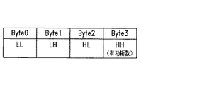
図28には、図23の第0009hブロックの第6h〜第9hバイトに記述される最終記録点の位置(EOS Point)を表すタイムコード(Time Data)の内容を示す。この図28において、最終記録点の位置(EOS Point)を表すタイムコードは、4バイトのBCDのコードとして表される。上記4バイトのうちの第1バイト(DATA-1)にはフレームを表すデータが、第2バイト(DATA-2)には秒を表すデータが、第3バイト(DATA-3)には分を表すデータが、第4バイト(DATA-4)には時を表すデータが格納される。また、空きビットを用いて種別が表される。なお、データを無効にするときは全てFFhで埋められる。
【0083】
図29には、図23の第0009hブロックの第Ah及び第Bhバイトの2バイト分で表されるカセットの挿入回数を示すスレッドカウント値(Thread Count)の一例を示す。なお、スレッドカウント値は、7FFFhを超えるとカウントアップしないようにすることも可能である。
【0084】
図30には、図23の第0009hブロックから第000Bhブロックまでの設定例を示し、図31には、図23の第000Ahブロックの第0h及び第1hバイトのキューポイントデータエリアの先頭アドレス(Data TOPP)の一例を示す。
【0085】
また、図32には、図23の第000Ahブロックの第2h〜第4hバイトの3バイト分で表される前記ファイルアロケーションテーブルの定義(FAT Definition)の内容を示す。これによれば、キュー点を容易に検索するためのキュー点のリストのファイルアドレス管理を行うことができる。アドレス管理を行う場合、データエリアの最後尾から前方向へキュー点がストアされている先頭アドレス(2バイト)を書き込む。その際、何個のキュー点毎にアドレスをストアするかを指定、及び、ストアされているキュー点パッケージの総数を既定する。この図32において、第000Ahブロックの第2hバイト(オフセットアドレス0)の第7〜第2ビットまではリザーブとなされ、第1及び第0ビットはキュー点パッケージのカウント値(Packed FAT Count)となされる。また、第3hバイト(オフセットアドレス1)の8ビットはストアされているキュー点パッケージの総数を表す16ビットのうちの上位8ビットとなされ、第4hバイト(オフセットアドレス2)の8ビットはストアされているキュー点パッケージの総数を表す16ビットのうちの下位8ビットとなされる。なお、キュー点パッケージのカウント値(Packed FAT Count)の第1,第2ビットが、”00”のとき未使用であることを示し、”01”のとき1キュー毎にアドレスを収納することを、”10”のとき4キュー毎にアドレスを収納することを、”11”のとき16キュー毎にアドレスを収納することを示している。
【0086】
図33には、図23の第000Ahブロックの第Bhバイトのフィールド周波数(FQ:Recodeing Frequncy)の内容を示す。この図33において、最上位の第7ビットはインターレースモードのとき”0”となされ、プログレッシブモードのとき”1”となされる。第6〜第3ビットはリザーブ、第5〜第3ビットはビデオ記録ビットレート(すなわちデータビットレート)情報が配され、第2から最下位の第0ビットはビデオ記録周波数(すなわちフィールド周波数)情報が配される。なお、上記第5〜第3ビットが”000”のときは、データビットレートが20Mbps(メガビット/秒)、”001”のときは30Mbps、”010”のときは40bps、”011”のときは50bps、”100”のときは所定のビデオ方式のビットレート、”101”はリザーブを表す。また、第2〜第0ビットの3ビットが”000”のときはフィールド周波数が29.97Hz、”001”のとき30Hz、”010”のときリザーブ、”011”のとき25Hz、”100”のとき23.98Hz、”101”のとき24Hzを表す。
【0087】
図34には、図23の第000Ahブロックの第Ch〜Fhバイトにおけるオーディオステータス(AD Status)の内容を示す。この図34において、第000Ahブロックの第Chバイト(オフセットアドレス0)の第7〜第4ビットまではチャンネルCH2のオーディオステータスが配され、第3〜第0ビットまではチャンネルCH1のオーディオステータスが配される。また、第000Ahブロックの第Dhバイト(オフセットアドレス1)の第7〜第4ビットまではチャンネルCH4のオーディオステータスが配され、第3〜第0ビットまではチャンネルCH3のオーディオステータスが配される。同様に、第000Ahブロックの第Ehバイト(オフセットアドレス2)の第7〜第4ビットまではチャンネルCH6のオーディオステータスが配され、第3〜第0ビットまではチャンネルCH5のオーディオステータスが配される。また、第000Ahブロックの第Fhバイト(オフセットアドレス3)の第7〜第4ビットまではチャンネルCH8のオーディオステータスが配され、第3〜第0ビットまではチャンネルCH7のオーディオステータスが配される。これら各チャンネルCH1〜CH8の4ビットのオーディオステータスは、例えば、”0100”のとき所定の方式(例えばATRAC3:商標)によるデータであることを表し、”0011”のとき所定の方式(例えばPana Data:商標)によるデータであることを、”0010”のとき所定の方式(例えばAC3:商標)によるデータであることを、”0001”のとき所定の方式(例えばDOLBY-E:商標)によるデータであることを、”0000”のときPCM(Pulse Code Modulation)のデータであることを示す。
【0088】
次に、図23に示したコモンエリアにおいては、上述の図23の第000Ahブロックの第0h及び第1hバイトに定義されているキューポイントデータエリアの先頭アドレス(Data TOPP)の値を設定することで、当該コモンエリアを拡張し、追加データを定義可能となされている。但し、メモリ容量の制限などにより、拡張領域へのデータ書き込みは必須ではない。
【0089】
前記図23に示したコモンエリアは拡張することが可能となされており、図35には、拡張コモンエリアのマネージメントテーブル(Extended Area Management Table)を示す。なお、この図35において、第0003hブロックから第000Ahブロックまでは図23と同じであるため、その部分の図示は省略してある。
【0090】
この図35において、第000Bhブロックの第0h〜第7hバイトまでの8バイトには拡張データ領域のデータフォーマットID(Extended Area Format ID)を表す文字列が配され、第8h〜第Ahバイトまでの3バイトには拡張データ領域のデータフォーマットのバージョン(Format Version)を表す文字列が配される。第000Chブロックの第0h〜第5hバイトまでの6バイトには当該ラベルのリール名(Reel Name。一つのみ定義可能)を表す文字列が配され、第6h〜第Bhバイトまでの6バイトには当該ラベルのEDL(EDiting List)が定義されたEDLファイル名(EDL File Name。一つのみ定義可能)を表す文字列が配される。また、第000Dhブロックの第0h〜第2hバイトの3バイトには当該ラベルが貼られた例えばカセットの収納フロア番号(Stocked Floor No.)を表す文字列が配され、第3h〜第8hバイトまでの6バイトには当該ラベルが貼られた例えばカセットの収納棚番号(Stocked Shelf No.)を表す文字列が、第9h〜第Bhバイトまでの3バイトには当該ラベルが貼られた例えばカセットの収納棚段番号(Stocked Step No.)を表す文字列が、第Ch〜第Fhバイトまでの4バイトには当該ラベルが貼られたカセットの収納単品位置(Stocked Position)を表す文字列が配される。また、第000Ehと第000Fhブロックの合計36バイトはリザーブとなっており、第0010hブロックの第0hバイトから第0012hブロックの第7hバイトまでの合計40バイトには当該ラベルに付けられるコメント(Comment)やメモ書きなどを表す文字列が配される。
【0091】
次に、上述したコモンエリアや拡張コモンエリアのデータエリア(Data Area)に格納されるデータについて説明する。当該データエリアには、各用途に合わせたデータが格納される。本実施の形態の場合、当該データエリアには前記メタデータなどが格納され、当該メタデータは、主に記録開始から終了までの個々のクリップ毎に付加されている。なお、上記共通領域にもメタデータの元になる情報があり、この共通領域の情報を利用してメタデータが生成される場合もあるが、以下の説明では、主に個々のクリップに付加され、読み書きの対象となるメタデータについて説明することにする。
【0092】
図36には、前記記録開始から終了までの1つのクリップエリアを表すキューポイントのデータフォーマットを示す。なお、このデータフォーマットにおいて、各項目も全体も可変長である。
【0093】
当該キューポイントのデータフォーマットでは、図36に示すように、ステータス(Status)フラグの各ビットが、各データ形式の「有り」/「無し」に対応しており、ステータスで指定したデータのみをステータスの後にビットの低い方から繋げるようになされている。この図36において、キューポイントのデータフォーマットは、2バイト分のステータス(Status)フラグ、フレーム(f)、秒(s)、分(m)、時(h)を表す4バイト分のキューポイント(CUE Point)、同じくフレーム、秒、分、時を表す4バイト分のインポイント(IN Point)、同じくフレーム、秒、分、時を表す4バイト分のアウトポイント(OUT Point)、番号を表す3バイト分のシーンナンバー(Scene No.)、同じく番号を表す4バイト分のカットナンバー(Cut No.)、1バイト分のテイクナンバー(Take No.)、4バイト分のリザーブされているユーザビット(User_bit)、フレーム、秒、分、時を表す4バイト分の実時間(Real_Time)、4バイト分の実データ(Real_Data)、最大53バイトのUMID(Unique Material IDentifier)データ、任意バイトの付加情報(Additional Information)からなる。なお、UMIDとは、映像や音声素材に割り当てられるグローバルにユニークなIDであり、例えばSMPTE330Mに定義されているものである。本実施の形態で使用するUMIDの詳細については後述する。
【0094】
ここで、図36に示した上記ステータスの2バイトを構成する16ビットのうち、第15ビットが”1”のとき記録スタート、”0”のときノーマルを表し、第14〜第13ビットが”00”のときデフォルト、”01”のときOK(ショット1)、”10”のときNG(ショット2)、”11”のときキープ(KEEP)を表し、第12ビットが”1”のとき付加情報(Additional Information)有り、”0”のとき付加情報無しを表し、第11ビットが”1”のときライトディセーブル(Write desable)、”0”のときライトイネーブル(Write enable)を表し、第10〜第9ビットが”00”のときUMIDデータ無し、”01”のとき6バイトのマテリアルデータ(Material Data)のみ、”10”のとき21バイトのベーシックデータ(Basic Data)、”11”のとき53バイトの拡張データ(Extended Data)が配されることを表し、第8ビットが”1”のときデータあり、”0”のときデータ無しを表している。また、当該ステータスの第7ビットが”1”のときリアルタイム(Real Time)有り、”0”のときリアルタイム無しを表し、第6ビットはリザーブ、第5ビットが”1”のときテイクナンバー(Take No.)有り、”0”のときテイクナンバー無しを表し、第4ビットが”1”のときカットナンバー(Cut No.)有り、”0”のときカットナンバー無しを表し、第3ビットが”1”のときシーンナンバー(Scene No.)有り、”0”のときシーンナンバー無しを表し、第2ビットが”1”のときアウトポイント(OUT Point)有り、”0”のときアウトポイント無しを表し、第1ビットが”1”のときインポイント(IN Point)有り、”0”のときインポイント無しを表し、第0ビットが”1”のときカットポイント(CUT Point)有り、”0”のときカットポイント無しを表している。
【0095】
図36に示した上記キューポイント(CUE Point)とインポイント(IN Point)、アウトポイント(OUT Point)とリアルタイム(Real Time)は、それぞれフレーム、秒、分、時間を表す時間情報であり、上記シーンナンバー(Scene No.)とカットナンバー(CUT No.)はそれぞれASCIIキャラクタである。また、テイクナンバー(Take No.)とリザーブ(Reserved)は0〜255のバイナリ値であり、データ(Data)は日、月、年をバイナリ値で表す時間情報である。なお、データとしては、上記フォーマットのデータが前記メモリタグの半導体メモリの容量に応じて格納され、データの終端は上記ステータスの2バイトが00hになされることで表される。
【0096】
ここで、上記図36のフォーマットの具体例として、図37には、ステータスの2バイトが01h,00h、つまり上記第0ビットが”1”で他の各ビットが全て”0”のとき(すなわちキューポイントのデータのみ)のデータ構造を示す。この図37の場合、トータル6バイトのみで表されることになる。また、図36のフォーマットの具体例として、図38には、ステータスの2バイトが07h,00h、つまり上記第0、第1、第2ビットがそれぞれ”1”で他の各ビットが全て”0”のとき(すなわちカットポイント、インポイント、アウトポイントのデータデータのみ)のデータ構造を示す。この図38の場合、トータル14バイトのみで表されることになる。
【0097】
次に、図39には、図36に示した上記ステータスの第12ビットが”1”(付加情報有り)となっている場合の、上記付加情報(Additional Information)のデータフォーマットを示し、図40には図39のより詳細な構造を示す。
【0098】
これら図39及び図40において、付加情報は、分類(Classification)、フロー(Flow)/モード(Mode)タイプ/データサイズ(DataSize:上位4ビット分)、データサイズの下位8ビット分、ペイロードデータ(Data)から構成され、分類(Classification)はASCII一文字で表され、フロー、モードタイプ、データサイズはバイナリ値で表される。上記フローが”1”であるとき、このサブセットの後に別のサブセットが続くことを示す。モードタイプはデータ型を表し、例えば、第5ビットが”0”で第4ビットが”0”のときバイナリ、第5ビットが”0”で第4ビットが”1”のときシフトJIS、第5ビットが”1”で第4ビットが”0”のときユニコード(unicode)を示す。
【0099】
上記分類(Classification)のASCII一文字が、例えば’C’のときはコメント(Comment)、’E’のときはEDL(EDiting List)、’M’のときはSMPTEメタデータバージョン1、’U’のときはwhole UMID、’S’のときはUMID署名メタデータ、’$’のときはユーザ定義を表す。上記分類のフィールドには、ASCII文字にて分類名が記述される。なお、現状ではASCII一文字となっているが、後述のディリミッタ(Delimiter)を”1”にすることで分類拡張が可能である。当該分類拡張を行った場合において、例えば’CMT’のときにはコメントを、’CID’のときにはカメラIDを表す。
【0100】
フロー/モードのフィールドの第7ビット(MSB)が分類のフィールドのディリミッタ(Delimiter)になっており、分類のフィールドの終わりを表している。フロー/モードのフィールドの第6ビットにはフロー制御(Flow Control)情報、第5及び第4ビットにはモード制御(Mode Control)情報が配される。上記フロー制御情報は、複数の付加情報を定義するのに使用される。例えば、上記第6ビットのフロー制御情報が”0”のとき付加情報の最後を示し、”1”のとき付加情報が後にもあることを示す。また、モード制御情報は、データエリアの文字コードタイプを定義する。例えば、上記第5,第4ビットが”00”のときはデータ内がバイナリコードで表されることを示し、”01”のときはデータ内がシフトJISコードで表され、”10”のときはデータ内がユニコード(unicode)で、”11”のとき使用不可であることを表している。
【0101】
データサイズ(データエリアのバイト数)は、フロー/モードのフィールドの第3〜第0ビット(上位4ビット分)と、次のデータサイズフィールドの1バイト(下位8ビット分)とで定義されており、12ビット構成になっている。したがって一度に伝送できるデータ数は4096バイトとなる。フロー制御情報が”1”であるとき、このサブセットの後に別のサブセットが続くことを示す。データの長さは0〜8191であり、0は分類のみの場合を表している。
【0102】
以上が、前記ラベル32に設けられた非接触メモリタグ37の半導体メモリのメモリマップとフォーマットの説明である。
【0103】
次に、前述した図36に記述されるUMIDについて説明する。
【0104】
図41には、SMPTE330Mに規定されている拡張UMID(Extended UMID)のデータフォーマットを示す。この図41において、SMPTE330Mに規定されている拡張UMIDは32バイトのベーシック(Basic)UMIDと同じく32バイトのシグネチャーメタデータ(Sifnature Metadata)の合計64バイトからなる。ベーシックUMIDは、12バイトのユニバーサルラベル(Universal Label)、1バイトのレングス(L)、3バイトのインスタンスナンバー(InstANCe No.)、16バイトとなるマテリアルナンバー(Material Number)からなり、また、シグネチャーメタデータは、8バイトのタイムデータ(Time/Data)、12バイトのスペーシャルコーディネイト(Spatial coodinate)、4バイトのカントリー(Country)コード、4バイトのオーガニゼイション(Organization)、4バイトのユーザコード(User Code)からなる。なお、マテリアルナンバー(Material Number)は、8バイトのタイムスナップ(Time Snap)と2バイトの乱数(Rnd)と5バイトのマシンノード(Machin Node)からなる。
【0105】
一方、本実施の形態では、UMIDを以下のようにして構成する。なお、以下の説明では、図10に示したカメラ一体型VTRの例えばカメラ処理部41或いはCPU21が生成するUMIDを例に挙げて述べる。
【0106】
本実施の形態のカメラ一体型VTRは、先ず、以下のようにしてベーシックUMIDを組み立てる。
【0107】
ベーシックUMIDの上記12バイトのユニバーサルラベル(Universal label)のうち第1バイトから第10バイトまでは固定のバイト列であるため、この時点では省略し、本実施の形態のVTRでは、前記磁気テープ30に記録する時や外部に出力する時に、それら第1〜第10バイトの固定バイト列を付加することとする。当該ユニバーサルラベルの第11、第12バイトは、例えば、画像と音声が同時記録であり、元素材である場合には、04h、11hとなる。また、レングス(L)も既知であるためこの時点では省略する。さらに、元素材の場合、インスタンスナンバーは、00h、00h、00hとなる。
【0108】
次に、マテリアルナンバーのタイムスナップ(Time Snap)は、図42に示すように、フレーム(Frame)、秒(Second)、分(Minute)、時(Hour)を表す8バイトからなり、これらの各値は、例えばVTR内部のタイムコードジェネレータが発生する時計情報から生成する。例えば西暦2000年5月31日である場合、その日付を表す2000.05.31をユリウス日に変換し、さらにその時計の設定からタイムゾーンが例えば日本であることを知り97hとして、上記タイムスナップの8バイトを揃える。また、上記乱数(Rnd)は、下位バイト(lower)と上位バイト(upper)からなり、それらに値を例えばソフトウェアで自走するM系列発生器で得る。
【0109】
さらに、マシンノード(Machine Node)は、VTRのCPU周辺に通常設けられている図示しないEEPROM等に書かれたシリアル番号から求める。
【0110】
以上により、図43に示すように21バイトからなるベーシックUMIDが組み立てられる。上記カメラ一体型VTRの場合、当該ベーシックUMIDは、記録スタートの時点で生成され、前記RAM22に書き込まれる。
【0111】
その後、上記カメラ一体型VTRの場合、この21バイトのベーシックUMIDは、図44に示すように、8バイトのタイムデータ(Time/Data)、12バイトのスペーシャルコーディネイト(Spatial coodinate)、4バイトのカントリー(Country)コード、4バイトのオーガニゼイション(Organization)、4バイトのユーザコード(User Code)からなる32バイトのシグネチャーメタデータと合わせて(合計は最大53バイトとなる)、前記磁気テープ30に記録されることになる。なお、このとき磁気テープ30には、同時に、タイムコードも書き込まれる。
【0112】
以上のようにして、幾つかのクリップに対応するデータが記録された後、磁気テープ30はイジェクトされることになるが、そのとき初めて、上記RAM22に蓄積されていた上記UMIDが、前記メモリタグ37の半導体メモリへの書き込まれる。但し、上記メモリタグ37の半導体メモリへ書き込む場合、当該半導体メモリの容量消費量を少なくするために、上記UMIDは以下のように圧縮されて記録される。すなわち、UMIDはクリップ単位で固有の値となされているため、カセットテープ一巻当たりで数十キロバイト程度になるが、例えばメモリタグ37の半導体メモリの容量が少ないような場合には、それら全てを記憶させるのは好ましくない。また、例えばUMIDを伝送容量の少ない伝送路に送信するような場合やアナログ機材などの場合は、それらUMIDに要する情報量を少なくした方が望ましい。したがって、本実施の形態では、上記UMIDを以下のように圧縮可能としている。
【0113】
ここで、各クリップのパッケージは、前述の図36の通りに構成されるが、本実施の形態のカメラ一体型VTRの場合は、例えば記録開始時のタイムコードをキュー(Cue)として、ベーシックUMIDを書き込むことになる。
【0114】
例えば最初のクリップは、フラグが2バイト、キューが4バイト、UMIDが21バイトの合計27バイトである。具体的には、例えば16進数表記で、図45の(a)ようになる。次のクリップでは、日付などは変化しないと考えられるため、UMIDは差分書式が使え、図45の(b)のように6バイトで済み、したがってパッケージのサイズは12バイトとなる。すなわち、図45の(b)は、差分書式により、前記図43のうち、タイムスナップのフレーム、秒、分、時の4バイトと乱数の2バイトの6バイトのみで済み、他の部分は省略することができる。
【0115】
以上のように、RAM22において、上記メモリタグ37の半導体メモリのメモリマップのイメージを構築した後、前記コイルアンテナ24によって、実際に前記非接触型メモリタグ37の半導体メモリに書き込む。
【0116】
次に、上記UMID以外のメタデータについて説明する。
【0117】
ここでは、予め前記非接触型メモリタグ37の半導体メモリの共通領域に主タイトル(一例として「The Tele-File」を挙げる)が書かれ、次のパッケージにサブタイトル(一例として「Application」を挙げる)が書かれているとする。また、本実施の形態のVTRが磁気テープ30に記録し、SDI ANCパケットとして外部に出力するメタデータは、これらタイトルの他、毎秒のフレーム数であるとする。
【0118】
先ず、本実施の形態のVTRにおいてメタデータを作成するところから述べる。
【0119】
上記主タイトルは上記メモリタグ37の半導体メモリから読み取る。当該主タイトルは、図46に示すように、メタデータである旨の宣言(8バイト)と、メインタイトルの符号(8バイト)と、長さ(1バイト)と、メインタイトルの文字を表すASCII文字(この例ではThe Tele-Fileを表すASCII文字13バイト)とからなるバイト列により表される。また、この図46のうち、最初のメタデータである旨の宣言の8バイトは常に同一なので省き、図47に示すように、残りのメインタイトルの符号と長さとメインタイトルの文字に、前記図36に示したステータスフラグや所望のイン、アウトポイントやヘッダなどの情報を付加して、クリップパッケージを生成する。なおこのとき、サブタイトルも上記半導体メモリから読み取っておくが、これは当該クリップを記録する時点でテープや外部に出力される。
【0120】
次に、例えばフレーム数についてはVTRの設定値から求める。例えば30フレーム/秒の場合16進数で1Ehである。これらの3種類のメタデータは、実際にはメタデータ宣言を略すと、図48に示す各行のようなバイト列になる。
【0121】
これらを外部やテープに出力する際には、先頭に06h 0Eh 2Bh 34h01h 01h 01h 01hを付加し、メモリタグ37の半導体メモリに書き込む際には、先頭にキュー点情報やヘッダを付加する。なお、どのクリップに、どのメタデータを付けるかはユーザの任意であり、一つのクリップに複数のメタデータ付けることも可能である。このように一つのクリップに複数のメタデータを付加することは、付加情報(Additional Information)のヘッダの第6ビット(Flow)の設定により可能である。
【0122】
ここでは、一例として、テープの先頭の00:58:30:00からカラーバーまでにフレーム数、本編最初のクリップ01:00:00:00以降に主題、また副題は次のパッケージに書かれているとすると、具体的なバイト列は図49に示すようになる。
【0123】
この図49の最後の1行は、メタデータを含まない例である。また、その上の行は副題であるが、これは元々書かれていたメタデータをそのまま書き戻したものである。さらにその上の行が主題で、これは上記メモリタグ37の半導体メモリの共通領域から引用した情報をメタデータに加工して、つまり、メモリタグ37の半導体メモリ上で書き写されたことになる。もちろん、図49の最初の1行のように、メモリタグ37以外の情報源を元にメタデータを作る場合もある。
【0124】
なお、上記メモリタグ37の半導体メモリから読み出されたメタデータを例えば外部等に出力する場合には、当該メモリタグ37から読み出されたUMIDからSMPTEに規定される正規のUMIDを復元しなければならない。本実施の形態では、メモリタグ37から読み出されたUMIDより正規のUMIDを復元する場合、図50に示す表の値を代入する。この図50に示す表の空欄には、上記メモリタグ37から読み出された値、すなわち前述のユニバーサルラベルの第11,第12バイトや、タイムスナップのフレーム、秒、分、時、乱数等を入れることで、正規のUMIDを復元する。図50のリースト(Least)モードの図中のp欄には前置を入れ、また、シグネチャーメタデータは最後にUMIDフラグの第2ビットが”1”であるときの指示に従う。但し、付加情報に所定の値(例えば’s’)があれば、そのクリップに限り付加する。
【0125】
なお、図48の(a)において示したようなUMIDは、例えば高精細度ビデオのSDI Yチャンネルの第10ライン直前のEAV(End of Active Video)以降に、図51のように置かれる。また、図48のタイトルを示すメタデータは、3項目纏めて、高精細度ビデオのSDI Yチャンネルの第10ラインのSAV(Start of Active Video)以降に、図52のように置かれる。これら図51、図52では、10ビットデータ列を16進数3桁で表現しており、下位2桁8ビット分はもとのメタデータの第7〜第0ビットと同じ内容で、第9ビットはそれらの偶数パリティ、第9ビットは第8ビットの反転したものである。また、図51、図52は説明のため、改行しさらに注釈も記述されているが、実際には連続したストリームであり、実際のシリアルデータ1.485G(ギガ)bpsになると、クロマのデータがワード単位で交互に配置される。すなわち、上記UMIDの例の場合は、3FF 3FF 000 000 000 000 2D8 2D8 200 000 200 3FF 200 3FF 200 2FD 200 101 200 120…のようになされる。
【0126】
以上のように、本実施の形態によれば、上述のようなUMIDを含むメタデータの書き込み/読み出しが可能となされたメモリタグ37を備えたラベル32がカセット31のカセットハーフに貼り付けられていることで、前述したようなVTRやカセット一体型VTRに内蔵されたリーダライタ26を用いて、メタデータを容易にアクセスでき、メタデータの読み書きができることになる。また、端末60に接続されたリーダライタ50を用いることで、特に磁気テープを再生することなくメタデータを容易にアクセスでき、メタデータの読み書きができることになる。さらに、例えば、先の例のように、収録前にタイトルを書き込むなどの操作が可能になるし、また、記録済みテープのメタデータを読み取る、或いは書き足す、といった作業も可能になる。また、内蔵する操作盤やセンサ類と付属する装置や機材から得た情報を使って生成したUMIDをメモリタグ37に書き込むことも可能となっている。このように、本実施の形態によれば、上記メモリタグを用いることにより、カセット31のようなリムーバブル記録メディアにおけるメタデータのハンドリングの幅が大きく広がる。
【0127】
また、前記図11の例のように、端末60がリーダライタ50を使用してりメモリタグ37の読み出しを可能とすることで、例えば カセット31の磁気テープ30のような記録メディアを再生せずに、メタデータが読み出せるようになり、その検索や確認に役立つ。このときのメタデータは、SMPTEのような規格化されたメタデータに則るので、他のシステムと連係することも可能となる。さらに、図1の例のように、入力映像信号にメタデータが含まれている場合には、それを抽出し、例えばキー操作や接続無しにメモりタグ37にも書き込める。また、入力信号にメタデータが含まれていなくても、本実施の形態によれば、キー操作や自動生成によりメタデータをメモリタグ37に書き込めることになる。
【0128】
また、本実施の形態によれば、SMPTE330Mで定義されたUMIDを、固定部分の省略と、ステータスフラグビットによる種類分け、及び共通部分の省略によって効率良くサイズ圧縮することが可能である。すなわち、項目毎のデータサイズが少なくて済むことになるので、メモリタグ37の半導体メモリに収容できる項目数が増加し、またデータ総量が減るのでアクセスに要する時間も短縮できる。また、その圧縮したUMIDを正規のUMIDに復元することも可能となっている。さらに、UMIDはカット毎に得られるので、編集後も活用できることになり、また、規格化されたUMIDに則るので、他のシステムと連係することも可能である。
【0129】
また、本実施の形態においては、メタデータが生成された時点で、メモリタグ37に当該メタデータを書き込むようになされており、記録エッセンス(素材)がどのような作業を通じて生み出され、現時点に存在しているかの履歴情報を各編集作業毎に、その場で記録し、それらを蓄積するデータフォーマットを備えているため、例えばカセットテープのような記録メディアの目録作成を行う際に、そのメモリタグ37に蓄積されたメタデータを目録作成のための元データとして活用することが可能となる。したがって、本実施の形態によれば、例えば収録などで発生させたメタデータをメモリタグ37に記録し、後段の例えば編集等の業務において、映像音声信号とは別の経路で、そのメタデータの受け渡しを行えるようになり、データの信頼性は飛躍的に向上し、それらのメタデータを活用してシステムの効率化に役立てることが可能となっている。また、目録作成作業の負担が軽減されることになり、事実上、作業が標準化され、映像素材などの2次利用が進み、資源の効率活用に役立つ。
【0130】
また、本実施の形態においては、上述したように、予めメモリタグ37に書き込まれていたメタデータを収録時にカセット31内に記録し、また、そのメタデータをメモリタグ37に書き戻すことや、メモリタグ37から読み出した情報を用いて生成したメタデータを収録時にカセット31内に記録し、また、当該メモリタグ37から読み出した情報を用いて新たに生成したメタデータをメモリタグ37に書き戻すこと、さらにはそれらメタデータを外部通信端子から出力可能としている。すなわち、本実施の形態によれば、予め確定しているメタデータやメタデータの元になる情報を、メモリタグ37に予め記録しておくことにより、収録時の入力作業に要する機材と手間を軽減可能となっている。また、本実施の形態によれば、収録時に生成したメタデータも含めて、確定したメタデータをメモリタグ37に書き戻しておくことにより、情報に一貫性を持たせている。さらに、本実施の形態によれば、確定したメタデータを記録と同時に出力し、それを例えば回線を通じて送信し、例えばデータベース化しておくことで、メディアの到着を待たずにデータベースが整理できる。また、回線が確保できない場合でも、メモリタグ37によって同じ情報が得られ、作業の自由度が高まる。
【0131】
また、本実施の形態においては、メモリタグ37に、記録スタート、グッドショット、ノーグッドショット、ログイン、ログアウト等のタイムコードデータを記録するようになされており、図11に示した編集システムにおいて、当該メモリタグ37に記録されているデータを読み込むことで、編集時に必要な部分の映像や音声信号素材のみデジタイジングすることが可能となっている。また、本実施の形態においては、同時に編集で新たに発生したデータ(編集日、編集者、リールナンバ、EDLナンバー等)や編集前のデータも含むメタデータを編集システム上でメモリタグ37に記録することが可能となっている。すなわち、本実施の形態によれば、メモリタグ37に収録などで発生させたメタデータを記録し、後段の編集システムに、映像及び音声信号とは別の経路でデータの受け渡しを行えるため、データの信頼性及び利便性が飛躍的に向上し、それらのメタデータを活用して、編集システムの効率化に役立てることが可能となっている。また、ロギング作業の負荷軽減により、事実上、作業が標準化され、資源の有効活用に役立つ。さらに、発生したその場で、メタデータを記録し、しかも、記録メディアと一体化されたメモリタグ37に格納するので、メディアを保管する際に必要な目録作成などの作業の効率化が図れる。
【0132】
以上説明したように、本実施の形態によれば、上記メモリタグ37に上記メタデータを記録し、再生可能としたことにより、以下のような運用が可能となる。
【0133】
上記メモリタグ37上のメタデータを用いた運用例の一つとして、本実施の形態では、上記非接触メモリタグ37に前述した記録点にかかわる情報を前記リーダライタにより書き込み、そして読み出し可能とすることにより、磁気テープ30上に記録された信号を再生することなく、カセット31の管理を行うことが可能となり、例えば、最終記録点への頭出しを容易にし、収録確認から次の収録までの時間短縮を可能とし、操作性を向上させたシステムや、例えば一度記録した個所の上書きを防止する誤消去防止システムなどを構築することが可能となる。
【0134】
すなわち例えば、前記第1の実施の形態の図1のVTRの場合には、カセット31がVTRに挿入されると、当該VTRに内蔵されている前記リーダライタ26は、上記カセット31に貼り付けられた前記非接触型のメモリタグ37を認識し、当該メモリタグ37からデータ(メタデータ)の読み出しを開始することになるが、このとき、当該読み出したメタデータのうち前記第0009hブロックの第2h,3hバイトに記述されたEOS点(最終記録点)のサーチに利用されるID(乱数)番号(EOSR-ID)、第4hに記述された最終記録点のカセットの供給側のリールの状態であるリメインステータス(RS)、第5hバイトに記述された最終記録点のカセットの供給側のリールの巻き径に対応した値であるリメインタイム(RT)、第6hバイトから第9hバイトまでに記述された最終記録点の位置(EOS Point)の情報をチェックする。これにより、カセット31の管理、最終記録点への頭出し、誤消去防止などが可能となる。すなわち例えば、一度記録した個所の上書きを防止するような場合には、最終記録点の特定が不可欠であり、本実施の形態では、上記メモリラベル37に記録した最終記録情報と磁気テープ30上に書かれた最終記録情報を照合し、最終記録位置の特定を行うことで、誤消去防止を可能としている。
【0135】
図53には、上記メモリラベル37に記録された最終記録情報と磁気テープ30上に記録されている最終記録情報とを照合して、最終記録位置の特定を行って記録を実行する場合の流れを示す。
【0136】
この図53において、先ず、例えば前記図1のVTRにカセット31が挿入され、記録の開始の指示(テープへの記録コマンドの発行)がなされると、先ず、当該VTRのCPU21は、当該カセット31が上書き禁止モードとなされていないかどうか判定し、上書き禁止モードとなされていないとき、すなわち例えば未記録テープや既に記録されている信号を全て上書きしてもよい状態となっているテープの場合、ステップS43において記録を開始させる。
【0137】
一方、上書き禁止モードとなっているときは、ステップS32に進む。ステップS32に進むと、CPU21は、記録ステータスをオンし、次に、前記リーダライタ26がメモリタグ37から読み取った前記メタデータ中のEOSデータが有効か否か判定する。このステップS33においてEOSデータが有効でないと判定したときはステップS39に進み、EOSデータが有効であると判定したときはステップS34に進む。
【0138】
ステップS34に進むと、CPU21は、EOS位置情報が有るか否か判定し、EOS位置情報が無いときはステップS36に進む。ステップS36に進むと、例えばアラームオンやモニタ29への表示により使用者に知らせ、その後ステップS37に進む。一方、ステップS34にてEOS位置情報があると判定したとき、ステップS35に進む。
【0139】
ステップS35に進むと、EOS点が所定のサーチ範囲内か否か判定する。すなわち前記リール巻き径をサーチ時間に換算したときに、EOS点が30秒以内でサーチできる範囲内にあるか否かの判定を行う。このステップS35において、EOS点が所定のサーチ範囲内に無い場合は、ステップS36にて使用者に知らせた後、ステップS37に進む。一方、サーチ範囲内にある場合はステップS37の処理に進む。
【0140】
ステップS34にてEOS位置情報が有ると判定され、且つ、ステップS35にてEOS点が所定のサーチ範囲内であると判定されて上記ステップS37の処理に進むと、CPU21は、EOS点までの距離に応じて5秒以内に記録が開始されるように、EOSサーチを行わせる。
【0141】
これに対して、上記ステップS35において上記所定のサーチ範囲内にEOS位置情報が無いと判定された状態で、上記ステップS37の処理に進むと、CPU21は、図54に示すようなEOSサーチ動作を行わせる。すなわち、例えばEOS点を0とし、例えば図中(a)に示すように、サーチ開始点P1からEOS点までの距離が、前記リール巻き径から換算されるサーチ時間で例えば−2分以内に無いときにはそのままEOS点に向かってサーチし、例えば図中(b)に示すように、サーチ開始点P2がEOS点から−2分以内にあるときには一旦逆方向にサーチした後にEOS点に向かってサーチする。また、例えば図中(c)に示すように、サーチ開始点P3がEOS点から2分以内にあるときや、例えば図中(d)に示すように、サーチ開始点P4がEOS点から2分以内に無いときにはそのままEOS点に向かってサーチする。
【0142】
図53に戻り、ステップS37の処理後、ステップS38の処理に進むと、CPU21は、EOSサーチが完了したか否か判定する。すなわち、ここでは、メモリタグ37から読み取った、前記EOSR-ID及びEOS Pointのタイムコードと磁気テープ30から読み取った値(タイムコード)とを比較して、EOSサーチが完了したか否か判定する。当該ステップS38において、EOSサーチが完了したときはステップS39に進む。
【0143】
一方、ステップS38においてEOSサーチが完了していないときは、ステップS40にてサーチ範囲がリール巻径をサーチ時間に換算してさらに2分を超えているか否か判定し、超えていないと判定したときはステップS37に戻り、超えていると判定したときはステップS44にて例えばアラームオンやモニタ29への表示によりその旨を使用者に知らせた後、ステップS45に進み、再生を開始すると共に操作盤の記録ボタン上に設けられているランプを点滅させる。この状態で、使用者が最終記録位置を見つけ、記録ボタンを押すと、EOSポイントが磁気テープ30上に記録される。
【0144】
また、ステップS39に進むと、再生が開始される。その後、ステップS41において、例えば15フレーム分程度の無記録部分が存在するか否かの判定が行われ、無記録部分が無いときはステップS44に進み、無記録部分があるときはステップS42に進む。
【0145】
ステップS42に進むと、上記アラーム等がオフされた後、ステップS43にて記録が開始される。
【0146】
以上説明したように、本実施の形態によれば、一度記録した個所の上書きを防止するシステムが構築でき、例えばメニュー操作やカセット記録防止機構の切り換えなしに、誤消去防止システムが構築できる。また、本実施の形態によれば、カセットの挿入、排出を繰り返しても、最終記録点の確認が容易であり、カセット挿入後の最終記録点への頭出し時間の短縮が可能であり、また、記録、再生確認後に、次の頭出し、記録準備期間の短縮が容易である。これらのことから、本実施の形態においては、誤消去防止と記録の操作性向上の相反する仕様を両立したシステムが構築できる。その結果、例えばVTR操作者の負担が軽減され、操作者や機器が変わっても誤消去が防止できる。また、ビデオエンジニアなどの専任技術者でなくても安全に収録ができ、その結果、人件費の削減など、効率的な運用が可能となる。
【0147】
次に、上記メモリタグ37上のメタデータを用いた運用例の一つとして、本実施の形態では、上記非接触メモリタグ37に前述したフィールド周波数(FQ)の情報を前記リーダライタにより書き込み、そして読み出し可能とすることにより、映像信号のフィールド周波数やデータビットレートが可変なシステムにおいて磁気テープ30を再生することなく、映像信号のフィールド周波数やデータビットレートについての情報を得ることができ、その方式に最適な処理を行うことが可能となされている。
【0148】
すなわち例えば、前記第1の実施の形態の図1のVTRの場合には、カセット31がVTRに挿入されると、当該VTRに内蔵されている前記リーダライタ26は、上記カセット31に貼り付けられた前記非接触型のメモリタグ37を認識し、当該メモリタグ37からデータ(メタデータ)の読み出しを開始することになるが、このとき、当該読み出したメタデータのうち上記第000Ahブロックの第Bhバイトに記録された図33に示したようなフィールド周波数(記録ビデオ周波数)及びデータビットレート(ビデオ記録ビットレート)情報をチェックすることにより、上記磁気テープ30に記録されている映像信号のフィールド周波数やデータレートを特定することが可能となる。本実施の形態のVTRは、上記フィールド周波数やデータレートを特定したとき、自己の機器内部における映像信号処理のための各種の設定値やパラメータ等を、上記フィールド周波数やデータレートに合わせるように切り換え(変更)るようになされており、これにより、磁気テープ30に記録されている映像信号に最適の信号処理を行うことが可能となる。したがって、本実施の形態のVTRによれば、間違ったフィールド周波数やデータレートでの処理を行うことによる映像ノイズの発生を防止でき、最適且つスムーズな映像再生や記録が可能となる。
【0149】
また、例えば前記第3の実施の形態の図11に示した編集システムにおいて、VTR71や72に上記カセット31が装填され、それらVTR71,72に装填されたカセット31内に記録されている信号をノンリニアで編集するような場合には、以下のようにして最適なオフライン編集を実現することができる。すなわち例えば、先にVTR71にカセット31が装填されたとすると、このときのVTR71は、前記リーダライタ26によって当該カセット31に貼り付けられたラベルのメモリタグ37からメタデータを読み取り、さらにその読み取られたメタデータを端末60に送る。端末60は、そのVTR71のリーダライタ26から送られてきたメタデータ中の上記フィールド周波数及びデータビットレート情報を記憶する。次に、VTR72にカセット31が装填されたとすると、当該VTR72もVTR1と同様に、前記リーダライタ26によってカセット31に貼り付けられたラベルのメモリタグ37からメタデータを読み取り、さらにその読み取られたメタデータが端末60に送られる。このときの端末60は、先にVTR71のリーダライタ26から送られてきた上記フィールド周波数及びデータビットレート情報と、その後VTR72のリーダライタ26から送られてきた上記フィールド周波数及びデータビットレート情報とを比較し、それら情報が同じ内容を示しているときには、そのままの状態で編集が可能であることを例えばモニタ上に表示等することで編集者に知らせ、一方、それら情報が異なる内容を示しているときには、そのままの状態で編集すると異なるフィールド周波数やデータビットレートの映像信号用いた編集がなされてしまうため編集することが出来ない旨の警告を例えばモニタ上に表示或いは音声により出力等することで編集者に知らせる。これにより、編集者に無駄な負担をかけることなく、編集時のシステム上のトラブルを未然に回避することが可能となる。
【0150】
また、例えば前記第3の実施の形態の図11に示した編集システムにおいて、VTR71や72に上記カセット31が装填され、それらVTR71,72に装填されたカセット31内に記録されている信号を前記編集装置74がオンラインのリニア編集を行うような場合には、以下のようにして最適なリニア編集を実現することができる。すなわち例えば、先にVTR71にカセット31が装填されたとすると、このときのVTR71は、前記リーダライタ26によって当該カセット31に貼り付けられたラベルのメモリタグ37からメタデータを読み取り、さらにその読み取られたメタデータを編集装置74に送る。編集装置74は、そのVTR71のリーダライタ26から送られてきたメタデータ中の上記フィールド周波数及びデータビットレート情報を用いて、自己が行うオンライン編集における映像信号処理のための各種の設定値やパラメータ等を、上記フィールド周波数及びデータビットレートに合わせるように切り換える(変更或いは初期化する)。次に、VTR72にカセット31が装填されたとすると、このときのVTR72もVTR1と同様に、前記リーダライタ26によってカセット31に貼り付けられたラベルのメモリタグ37からメタデータを読み取り、さらにその読み取られたメタデータが編集装置74に送られる。このときの編集装置74は、先にVTR71のリーダライタ26から送られてきた上記フィールド周波数及びデータビットレート情報と、その後VTR72のリーダライタ26から送られてきた上記フィールド周波数及びデータビットレート情報とを比較し、それら情報が同じ内容を示しているときには、そのままの状態でリニア編集が可能であることを例えばフロントパネルのモニタ上に表示等して編集者に知らせると共に、その編集者からの編集操作情報に応じてオンライン編集を実行する。一方、それらフィールド周波数及びデータビットレート情報が異なる内容を示しているとき、編集装置74は、そのままの状態で編集すると異なるフィールド周波数及びデータビットレートの映像信号用いた用いた編集がなされてしまうため編集することが出来ない旨の警告を例えばフロントパネルのモニタ上に表示等することで編集者に知らせる。これにより、編集者に無駄な負担をかけることなく、編集時のシステム上のトラブルを未然に回避することが可能となる。
【0151】
なお、上記の説明では、カセット31がVTRに装填され、そのVTRに内蔵されているリーダライタ26によりメモリタグ37から情報を読み出す例を述べたが、例えば、VTRに装填される前のカセット31に対して、ハンディタイプのような単体として構成されているリーダライタ50を用いて、予めフィールド周波数及びデータビットレート情報を確認しておくことも可能である。この場合、上記したノンリニア編集を行うシステムにおいては、そのシステム自身の設定(端末60にシステムの設定として記憶されている値)と、当該リーダライタ50が読み取ったカセット31内に記録されている映像信号のフィールド周波数及びデータビットレート情報とを比較することで、システムの設定とは異なる設定のカセット31を検出することができる。これにより、編集作業前に編集不能なカセットを把握することが可能となる。また、ハンディタイプのリーダライタ50に予めシステムで使用しているフィールド周波数及びデータビットレート情報を記憶させておき、編集に使用したいカセット31のメモリタグ37からフィールド周波数及びデータビットレート情報を読み取り、上記予め記憶している情報と比較することにより、端末60等を用いなくとも、ノンリニア編集システムで取り扱えないカセットを検出することができる。
【0152】
以上説明したように、本実施の形態によれば、編集システムを運用、稼働させる前に運用不能状態を検出すること、すなわちカセット31へ実際に信号を記録再生する前に、映像信号のフィールド周波数及びデータビットレートを検知して警告発生などの回避措置をとることができるので、間違ったフィールド周波数及びデータビットレートの映像信号同士を編集することによる映像ノイズの発生などの不具合を未然に防止でき、スムーズ編集が可能となる。また、このように、映像ノイズの発生を未然に防止できるため、例えば誤った編集により発生する映像ノイズによってモニタ等が故障してしまうような事態を回避することができ、メンテナンスコストの削減にも効果がある。さらに、本実施の形態によれば、例えばハンディタイプのリーダライタ50などを使用して、オフライン環境下でシステムで運用できないカセットを特定できるので、結果として、使用不能なカセットの編集システム内への進入を未然に防止できる。このように、本実施の形態によれば、編集システムの運用不能状態を自動検出、回避できるため、システム運用者(編集作業者)の負担を軽減することが可能となっている。
【0153】
次に、上記メモリタグ37上のメタデータを用いた運用例の一つとして、本実施の形態では、上記非接触メモリタグ37に前述のようなオーディオステータス(AD Status)の情報を前記リーダライタにより書き込み、そして読み出し可能とすることにより、磁気テープ30上に記録された信号を再生することなく、その磁気テープ30に記録されている音声信号の記録方式についての情報を得ることができ、その方式に最適な処理を行うことが可能となされている。
【0154】
すなわち例えば、前記第1の実施の形態の図1のVTRの場合には、カセット31がVTRに挿入されると、当該VTRに内蔵されている前記リーダライタ26は、上記カセット31に貼り付けられた前記非接触型のメモリタグ37を認識し、当該メモリタグ37からデータ(メタデータ)の読み出しを開始することになるが、このとき、当該読み出したメタデータのうち上記第000Ahブロックの第Ch〜Fhバイトに記録されたオーディオステータス情報をチェックすることにより、上記磁気テープ30に記録されている音声信号の記録方式を特定することが可能となる。本実施の形態のVTRは、上記音声信号の記録方式を特定したとき、自己の機器内部における音声信号処理のための各種の設定値やパラメータ等を、上記音声信号の方式に合わせるように切り換え(変更)るようになされており、これにより、磁気テープ30に記録されている音声信号に最適の信号処理を行うことが可能となる。したがって、本実施の形態のVTRによれば、間違った音声信号処理を行うことによる音声ノイズの発生を防止でき、最適且つスムーズな音声再生や記録が可能となる。
【0155】
また、例えば前記第3の実施の形態の図11に示した編集システムにおいて、VTR71や72に上記カセット31が装填され、それらVTR71,72に装填されたカセット31内に記録されている信号をノンリニアで編集するような場合には、以下のようにして最適なオフライン編集を実現することができる。すなわち例えば、先にVTR71にカセット31が装填されたとすると、このときのVTR71は、前記リーダライタ26によって当該カセット31に貼り付けられたラベルのメモリタグ37からメタデータを読み取り、さらにその読み取られたメタデータを端末60に送る。端末60は、そのVTR71のリーダライタ26から送られてきたメタデータ中の上記オーディオステータス情報を記憶する。次に、VTR72にカセット31が装填されたとすると、当該VTR72もVTR1と同様に、前記リーダライタ26によってカセット31に貼り付けられたラベルのメモリタグ37からメタデータを読み取り、さらにその読み取られたメタデータが端末60に送られる。このときの端末60は、先にVTR71のリーダライタ26から送られてきた上記オーディオステータス情報と、その後VTR72のリーダライタ26から送られてきた上記オーディオステータス情報とを比較し、それら情報が同じ内容を示しているときには、そのままの状態で編集が可能であることを例えばモニタ上に表示等することで編集者に知らせ、一方、それら情報が異なる内容を示しているときには、そのままの状態で編集すると異なる方式の音声信号用いた編集がなされてしまうため編集することが出来ない旨の警告を例えばモニタ上に表示或いは音声により出力等することで編集者に知らせる。これにより、編集者に無駄な負担をかけることなく、編集時のシステム上のトラブルを未然に回避することが可能となる。
【0156】
また、例えば前記第3の実施の形態の図11に示した編集システムにおいて、VTR71や72に上記カセット31が装填され、それらVTR71,72に装填されたカセット31に記録されている信号を前記編集装置74がオンラインのリニア編集を行うような場合には、以下のようにして最適なリニア編集を実現することができる。すなわち例えば、先にVTR71にカセット31が装填されたとすると、このときのVTR71は、前記リーダライタ26によって当該カセット31に貼り付けられたラベルのメモリタグ37からメタデータを読み取り、さらにその読み取られたメタデータを編集装置74に送る。編集装置74は、そのVTR71のリーダライタ26から送られてきたメタデータ中の上記オーディオステータス情報を用いて、自己が行うオンライン編集における音声信号処理のための各種の設定値やパラメータ等を、上記音声信号の記録方式に合わせるように切り換える(変更或いは初期化する)。次に、VTR72にカセット31が装填されたとすると、このときのVTR72もVTR1と同様に、前記リーダライタ26によってカセット31に貼り付けられたラベルのメモリタグ37からメタデータを読み取り、さらにその読み取られたメタデータが編集装置74に送られる。このときの編集装置74は、先にVTR71のリーダライタ26から送られてきた上記オーディオステータス情報と、その後VTR72のリーダライタ26から送られてきた上記オーディオステータス情報とを比較し、それら情報が同じ内容を示しているときには、そのままの状態でリニア編集が可能であることを例えばフロントパネルのモニタ上に表示等して編集者に知らせると共に、その編集者からの編集操作情報に応じてオンライン編集を実行する。一方、それらオーディオステータス情報が異なる内容を示しているとき、編集装置74は、そのままの状態で編集すると異なる方式の音声信号用いた編集がなされてしまうため編集することが出来ない旨の警告を例えばフロントパネルのモニタ上に表示等することで編集者に知らせる。これにより、編集者に無駄な負担をかけることなく、編集時のシステム上のトラブルを未然に回避することが可能となる。
【0157】
なお、上記の説明では、カセット31がVTRに装填され、そのVTRに内蔵されているリーダライタ26によりメモリタグ37から情報を読み出す例を述べたが、例えば、VTRに装填される前のカセット31に対して、ハンディタイプのような単体として構成されているリーダライタ50を用いて、予めオーディオステータス情報を確認しておくことも可能である。この場合、上記したノンリニア編集を行うシステムにおいては、そのシステム自身の設定(端末60にシステムの設定として記憶されている値)と、当該リーダライタ50が読み取ったカセット31内に記録されている音声信号についてのオーディオステータス情報とを比較することで、システムの設定とは異なる設定のカセット31を検出することができる。これにより、編集作業前に編集不能なカセットを把握することが可能となる。また、ハンディタイプのリーダライタ50に予めシステムで使用しているオーディオステータス情報を記憶させておき、編集に使用したいカセット31のメモリタグ37からオーディオステータス情報を読み取り、上記予め記憶している情報と比較することにより、端末60等を用いなくとも、ノンリニア編集システムで取り扱えないカセットを検出することができる。
【0158】
以上説明したように、本実施の形態によれば、編集システムを運用、稼働させる前に運用不能状態を検出すること、すなわちカセット31に実際に信号を記録再生する前に、音声信号の記録方式を検知して警告発生などの回避措置をとることができるので、間違った方式の音声信号同士を編集することによる音声ノイズの発生などの不具合を未然に防止でき、スムーズ編集が可能となる。また、このように、音声ノイズの発生を未然に防止できるため、例えば誤った編集により発生する音声ノイズによってスピーカやアンプ等が破壊してしまうような事態を回避することができ、メンテナンスコストの削減にも効果がある。さらに、本実施の形態によれば、例えばハンディタイプのリーダライタ50などを使用して、オフライン環境下でシステムで運用できないカセットを特定できるので、結果として、使用不能なカセットの編集システム内への進入を未然に防止できる。このように、本実施の形態によれば、編集システムの運用不能状態を自動検出、回避できるため、システム運用者(編集作業者)の負担を軽減することが可能となっている。
【0159】
次に、上記メモリタグ37上のメタデータを用いた運用例の一つとして、本実施の形態では、上記非接触メモリタグ37に上述のようなカセット31のスレッド回数の情報を前記リーダライタにより書き込み、そして読み出し可能とすることにより、カセット31の管理を行うことが可能となる。
【0160】
すなわち例えば、前記第1の実施の形態の図1のVTRの場合には、カセット31がVTRに挿入されると、当該VTRに内蔵されている前記リーダライタ26は、上記カセット31に貼り付けられた前記非接触型のメモリタグ37を認識し、当該メモリタグ37からデータ(メタデータ)の読み出しを開始することになるが、このとき、当該読み出したメタデータのうち前記第0009hブロックの第Ah,Bhバイトに記録されたスレッド回数の情報をチェックすることにより、上記カセット31の使用状況を知ることができ、それに応じて使用の可否や後何回使用可能であるかなどの管理が可能となる。なお、当該管理の項目とそれを利用したオペレーションとしては、例えば、「カセットのVTRへのスレッド回数管理」、「カセットのスレッド回数監視とそれに応じた警告表示」、「カセットの使用回数管理システム」が挙げられる。
【0161】
先ず、カセットのスレッド回数管理に関して説明する。
【0162】
例えば前記図1において、VTRにカセット31が装填されたとすると、このときのVTRは、前記リーダライタ26によって当該カセット31に貼り付けられたラベルのメモリタグ37からメタデータを読み取り、その読み取られたメタデータのうち前記スレッド回数の情報をチェックし、さらにその回数を1インクリメントしてメモリタグ37に記録されているスレッド回数の情報を書き換える(更新する)。
【0163】
ここで、本実施の形態では、上記スレッド回数の情報をチェックし、スレッド回数がある値以上になった時には、警告を発する機能と、そのチェック結果に応じた処理として、以下のようなことが可能となされている。
【0164】
例えば図1のVTRには、操作盤28のモニタ29上を用いて、メンテナンス用の表示を実行する機能を有している。そして、メンテナンス表示機能を起動すると、カセットスレッド回数を確認することが可能となされている。また、本実施の形態のVTRは、挿入されたカセットスレッド回数がある値以上になると、警告を表示する機能を有して、また、ある値以下であっても磁気テープ30から再生した信号のエラーレベルにより、警告を表示するか否かの判定機能をも有している。
【0165】
上記スレッド回数に応じた警告表示のフローは、図55に示すようになる。この図55において、VTRは、先ずステップS10として、カセット31が挿入されると、ステップS11として、当該カセット31に貼り付けられた前記ラベル32のメモリタグ37のデータを前記リーダライタ26により読み取り、その読み取られたメタデータのうち前記スレッド回数の情報をチェックし、さらにそのスレッド回数が警告表示を行う設定値以上となっているか否かの判定を行う。
【0166】
このステップS11での判定によりスレッド回数が警告表示設定値以上であると判定されたときには、ステップS15として、操作盤28のモニタ29上にカセット使用状況警告の表示を行う。
【0167】
一方、ステップS11にてスレッド回数が警告表示設定値に満たないと判定したとき、ステップS12としてそのカセット31を用いて再生を行う。
【0168】
また、このとき、ステップS13として、上記スレッド回数がエラーレート監視を実行すべきとして予め設定されている値以上か否かの判定を行う。
【0169】
このステップS13での判定により、エラーレート監視を実行すべきとして予め設定されている値未満であると判定された場合はステップS16として次の処理を実行する。
【0170】
一方、ステップS13において、エラーレート監視を実行すべきとして予め設定されている値以上であると判定された場合は、次のステップS14において、磁気テープ30から再生された信号のエラーレートが警告表示を行う設定値以上となっているか否かの判定を行う。
【0171】
このステップS14において、エラーレートに基づく警告表示を実行すべきとして予め設定されている値未満であると判定された場合はステップS16にて次の処理を実行する。
【0172】
一方、ステップS14において、エラーレートに基づく警告表示を実行すべきとして予め設定されている設定値以上であると判定されたときには、ステップS15として、操作盤28のモニタ29上にカセット使用状況警告の表示を行う。
【0173】
以上により、VTRの操作者やカセットの管理者は、カセットの状態を知ることができる。
【0174】
次に、上記スレッド回数に基づくカセット管理について、前記図11の構成を例に挙げて説明する。
【0175】
前記図11の構成では、端末60が外部ハンディタイプのリーダライタ50を用いて、カセット31のラベル32に設けられたメモリタグ37の内容を読み取り可能となされており、また、端末60には本実施の形態に係るカセット使用管理ソフトウェアがインストールされている。すなわち、当該カセット使用管理ソフトウェアは、前記メモリタグ37を初期発行する機能や、メモリタグ37に記憶された情報を使ってカセットスレッド回数情報を管理する機能などが盛り込まれている。具体的には、カセット31のラベル32に設けられたメモリタグ37に記録された情報を前記リーダライタ50が読み取り、当該カセットの使用頻度とその使用目的によって廃棄や使用目的の変更などを管理ソフトウェアが使用者に対して指示する。
【0176】
図56には、上記カセットの管理を行う場合の管理表の一例を示す。
【0177】
各カセット31のラベル32に設けられたメモリタグ37内の情報を上記リーダライタ50により読み取ると、管理ソフトウェアは、端末60のモニタ上に、例えば図56に示すようなメモリラベル37から読み取られた情報に基づく管理表を表示させ、また、使用目的とスレッド回数の情報を組み合わせて、カセットの状況を使用者に対して示唆する。上記管理表について具体的に説明すると、この図56において、例えばテープIDがHD−10001となされたカセットについては、使用目的がライブラリー用であり、現在のスレッド回数が6回であるため「優」(すなわち十分に使用可能である)と判定し、テープIDがD2−22029となされたカセットについては、使用目的がドラマ用であり、現在のスレッド回数が20回であるため可(すなわちまだ使用可能である)と判定する。また、テープIDがSX−23478となされたカセットについては、使用目的が使い回しであり、現在のスレッド回数が100回であるため使用不可(すなわちこれ以上使用するべきではない)と判定される。また、テープIDがIMX−67870となされたカセットについては、使用目的が使い回しであり、現在のスレッド回数が20回であるため「良」(すなわち使用可能である)と判定される。ここで、例えば、D2−22029となされたカセットとIMX−67870となされたカセットのスレッド回数は同じであるが、判定結果が異なっている。これは、ドラマ作成ではできるだけ良好な(磁気テープの状態が良好な)カセットを使用する必要があるのに対し、使い回し用途では多少の劣化は許容されるためである。また、使い回しのテープは、スレッド回数が100回以下で廃棄と既定されていた場合、図56においてスレッド回数が100となっている上記テープIDがSX−23478となされたカセットについては、テープ廃棄処理の対象となり、例えば「2000年6月19に廃棄予定」のようなコメントが入れられる。
【0178】
また、本実施の形態の場合は、上記図56のような管理表に対応した図11の端末60とハンディタイプのリーダライタ50を用い、カセット31のラベルに設けられたメモリタグ37から直接に前記スレッド回数の情報を読み取り可能にすることにより、例えば図57に示すように、棚300に収納された複数のカセット31のメモリタグ37の情報を順次スキャンすることで、それら棚300に収納された各カセット31の廃棄の要否を検出でき、また、各棚が使用目的別に分けられているとき、その使用目的に合わないカセットを見つけ出すことなどが可能となる。
【0179】
以上説明したように、本実施の形態によれば、カセットの使用回数や磁気テープ30の劣化状況が把握できるため、客観的な方法でのカセットの償却を判断できる。また、本実施の形態によれば、劣化した磁気テープ30の使用を未然に防止できるので、安定した記録、再生が管理可能となる。さらに、使用用途が使い回しとなっているカセットやワークカセット、それに対して使用用途がアーカイブ用カセットなどの使い分け管理を行うことができるようになるため、運用コスト削減にも効果がある。また、本実施の形態によれば、必要以上に使い込まれたテープを機器が自動的に検出し、警告発生などの安全措置が可能となっているため、結果、システム運用者がそれらを管理する際の負担を軽減することが可能となる。その他、本実施の形態によれば、ハンディタイプのリーダライタ50などを使用することで、オフライン環境下でのテープ管理が可能となる。
【0180】
次に、図58〜図62を用いて、前記非接触型メモリタグ37とそのリーダライタ26,50の詳細について説明する。
【0181】
図58には、非接触型メモリタグ37とリーダライタ26の機能を表す概略的な構成を示す。
【0182】
非接触型メモリタグ37は、電磁界を周辺に形成する機器であるリーダライタ26との相対距離が電磁界に感応可能な限界距離以内になると、電磁界に感応して作動し、リーダライタ26との間で非接触により情報の授受を行う。
【0183】
ここで非接触型メモリタグ37の詳細な構成の説明に先立って、非接触型メモリタグ37の主要部の外観と、このメモリタグ37をリーダライタ26により使用する際の動作を簡単に説明する。
【0184】
図59には、ワンチップ構成で実現された非接触型メモリタグ37の外観を示す。この図59に示すように、当該メモリタグ37は、基台となるチップ上に導電パターンがループ状に形成されたコイルアンテナ36が配され、このコイルアンテナ36にICチップ35とキャパシタCが接続されて構成される。なお、キャパシタCは共振周波数を調整するものである。
【0185】
非接触型メモリタグ37は、リーダライタ26のコイルアンテナ24との間で電磁界を媒体として誘導結合され、相互誘導により非接触で情報を送受するとともに電力供給を受けるコイルアンテナ36と、このコイルアンテナ36にそれぞれ接続された復調部102および変調部103を備える送受信部107と、上記コイルアンテナ36にそれぞれ接続された電源部104と、クロック抽出部105と、全体の動作を制御する制御部101と、この制御部101に接続された符号化復号化部106と、さらに制御部101に接続された前記記憶保持動作が不要な書き換え可能な半導体メモリ100とを備える。
【0186】
復調部102はコイルアンテナ36に発生した誘導電流を等化処理し、さらに検波及び復調して情報を復元し、制御部101へ供給する。また、変調部103は、制御部101から供給された再生情報に符号化を施したレスポンス情報に基づき負荷インピーダンスをコイルアンテナ36に断続させる制御をすることで反射波を変調処理するか、或いはレスポンス情報に基づき電源部104に直接または間接に接続された負荷を断続させる制御をするか、或いはレスポンス情報で変調(例えばASK変調)した別周波数の搬送波をコイルアンテナ36へ給電する構成であるかの、いずれかの構成とする。
【0187】
これをさらに説明すると、レスポンス情報に基づきコイルアンテナ36の負荷インピーダンスを制御する構成では、リーダライタ26から電磁界の作用を受け続けているコイルアンテナ36から搬送波の反射波を発射させる際に、レスポンス情報に基づき負荷インピーダンスを切換制御することによりコイルアンテナ36の反射率を制御し、これにより反射波を前述したレスポンス情報で変調されたものにする。
【0188】
一方、レスポンス情報に基づき電源の負荷を制御する構成では、レスポンス情報に基づいた負荷の切換制御により電源部104にかかるロードを切換えて誘導結合状態にあるメモリタグ37側のインピーダンスを変動させることで変調するように構成される。このメモリタグ37側のインピーダンス変動は、誘導結合状態にあるリーダライタ26側で、コイルアンテナ24の端子電圧変動や投入電力量の変動として検出される。
【0189】
上記のように、メモリタグ37のコイルアンテナ36がリーダライタ26の発した電磁波を受信した際に相互誘導により生成する誘導電流を処理して情報を復調し、ついでリーダライタ26へ発信する情報に基づきコイルアンテナ36の負荷インピーダンスを制御して送信するか(搬送波の反射波による情報送信)、リーダライタ26へ発信する情報に基づきメモリタグ37側の電源の負荷を制御して送信するか(インピーダンス変動による情報送信)、リーダライタ26へ発信する情報により別周波数の搬送波に変調を施してコイルアンテナ36へ給電して送信するか(メモリタグ37の有する送信機能が発する別周波数の送信波による情報送信)、等の何れかにより実現される。
【0190】
電源部104は、コイルアンテナ36が電磁界を介して相互誘導で発生させた高周波の誘導電流を受けて整流し、これを電源として各部に電力供給する。さらに安定な直流電圧を出力するための電圧安定化回路を備えることも可能である。そして各部はこの供給電力によって作動することができる。したがって、このメモリタグ37は電池などの他の電源を特に準備する必要はない。但し電池などの他の電源を主電源または副電源とする構成も可能であることは言うまでもない。
【0191】
クロック発生部105は分周回路を備え、コイルアンテナ36で受信した搬送波に基づいて搬送周波数のクロック信号を出力するとともに、このクロック信号を分周して、各ディジタル回路部の動作基準クロックとなるマスタークロックを生成して出力する。
【0192】
半導体メモリ100は、前述したように、このメモリタグ37を有するラベルが貼り付けられたカセット31及び収録された素材に関連するメタデータ等を記録するものであり、制御部101の制御の元で、前述したようなメモリマップ上で各情報が記録再生されるものである。
【0193】
制御部101は、受信時において送受信部107から付与される復調された信号を符号化復号化部106へ送る。符号化復号化部106は、制御部101から供給される情報の復号化とCRC符号に基づく誤り修正とを施して制御部101へ返送し、制御部101はこれより指示情報を抽出する。このようにしてリーダライタ26から電磁界を媒介して付与された情報が復元される。
【0194】
また、符号化復号化部106は返信時には制御部101から供給される情報にCRC符号等の誤り訂正用コードを付与し、誤り訂正用コードを付与したデータを符号化したレスポンス情報を制御部101へ返送する。
【0195】
符号化復号化106はデータのエラー訂正機能を含むが、この他にデータの暗号化/復号化機能を備える構成とすることも可能である。さらにCRC方式に限定されず他のエラー訂正回路を適用することも可能である。
【0196】
制御部101は、クロック抽出部105から供給されたクロックに基づき、復調部102から供給された復調信号を符号化復号化部106へ送付し、エラー訂正された信号に基づき各種の情報を抽出し、また記録用の情報を分離抽出して、これら指示情報を解析し、所定の処理を所定の手順で逐次実行する、シーケンス制御機能を備えた半導体ロジック制御回路として構成される。このような所定の手順に従い、条件を判定して例えば複数ゲートの開閉を時系列で逐次実行する半導体シーケンスコントローラの技術は広く適用されており、制御部101はこの技術を利用したものである。
【0197】
一方、制御部101を介して情報を受けた変調部103は、所定の変調方式に基づく変調処理を実行する。これを受けて送受信部107は変調信号をコイルアンテナ36を介してリーダライタ26へ送る。この送信は前述したように、当該メモリタグ37の有する送信機能による送信波によるか、反射波によるか、またはインピーダンス変動による原理で為される。
【0198】
次に、リーダライタ26によるメモリタグ37内の半導体メモリ100の内容を検出する原理を、図60及び図61を用いて説明する。
【0199】
リーダライタ26側のコイルアンテナ24を第1アンテナとし、メモリタグ37のコイルアンテナ36を第2アンテナとすると、第1および第2アンテナが向き合い、第1アンテナに流れる電流により発生した磁界が第2アンテナにより捕捉される際に、第1アンテナに流れる電流の変化に対応してこの電流の作る磁界が変化する。これにより第2アンテナを貫く磁束に変化が生じ、相互誘導によって第2アンテナに起電力が発生する。第2アンテナに発生する起電力V2は、第1アンテナの電流I1の変化に比例し、Mを相互インダクタンスとした同調条件下において式(1)で示され、第2アンテナを流れる電流I2は、接続された回路特性に依存する。
【0200】
V2=M(dI1/dt) (1)
一方、メモリタグ37のコイルアンテナ36(第2アンテナ)には、負荷インピーダンスとして抵抗やリアクタンス(誘導性リアクタンスωLまたは容量性リアクタンス1/ωC)が接続可能であり、且つ、この負荷インピーダンスの第2アンテナへの断続は、メモリタグ37から送信されるデータの内容(「1」か「0」)によって制御される。
【0201】
上記のようにリーダライタ26を1次側とし、このリーダライタ26と相互誘導により誘導結合されたメモリタグ37を2次側として、2次側の総インピーダンスがZであるとき、図60に示される誘導結合4端子網として扱うことができる。ここで1次側において測定されるインピーダンスZieは、以下のように算出される。
【0202】
ωを角周波数、リーダライタ26のコイルアンテナ24のインダクタンスをL1、起電力をV1、電流をI1、またメモリタグ37のコイルアンテナ36のインダクタンスをL2、起電力をV2、電流をI2、さらにコイルアンテナ24と36の相互インダクタンスをMとして、同調条件下で誘導起電力V1は、式(2)で表され、また、誘導起電力V2は、式(3)で表される。
【0203】
V1=jω*L1*I1+jω*M*I2 (2)
V2=jω*M*I1+jω*L2*I2 (3)
ここで、電流I2の方向が逆になることから、式(4)になる。
【0204】
V2=−Z*I2 (4)
以上から、リーダライタ26側のインピーダンスZieは、記号「**」を2乗として、第1項としてのjω*(L1−M**2/L2)と、第2項としてのjω*(M**2)*Z/L2*(Z+jω*L2)の和となる。
【0205】
ここで、式(5)、式(6)のように前項第2項を変形すると、1/(u2+u3)となる。
【0206】
u2=L2/jω*(M**2) (5)
u3=(L2**2)/Z*(M**2) (6)
したがって、前記第1項をu1とすると、リーダライタ26側のインピーダンスZieは、式(7)のようになる。
【0207】
Zie=u1+1/(u2+u3) (7)
この結果、誘導結合4端子網の等価回路は図61のように示すことができる。
【0208】
メモリタグ37側のインピーダンスZを、送信するデータの内容(「1」か「0」のうちのいずれか一方、例えば「1」)に応じて無限インピーダンスとするよう回路を制御する場合は、式(8)の項が無限小となり、よってデータが「1」の状態は、リーダライタ26側で式(9)のインピーダンスとして観測される。
【0209】
u3=(L2**2)/Z*(M**2) (8)
Zie1=jω*L1 (9)
一方、メモリタグ37側のインピーダンスZを、データの内容(「1」か「0」のうちのいずれか一方、例えば「0」)に応じてゼロインピーダンスとする場合は、1/(u2+u3)の項が無限小となり、よってデータの「0」の状態は、リーダライタ26側で式(10)のインピーダンスとして観測される。
【0210】
Zie0=jω*(L1−M**2/L2) (10)
これは、コイルアンテナ24と36の式(11)の結合定数kを用いて、式(12)として示される。
【0211】
k**2=M**2/L1*L2 (11)
Zie0=jω*L1*(1−k**2) (12)
このように、メモリタグ37側のデータの「1」か「0」の状態は、リーダライタ26側で上記の異なるインピーダンス値Zie1、Zie0として観測されることにより、容易にデータの「1」か「0」の状態を検出することができる。
【0212】
さらに、メモリタグ37側のインピーダンスZをゼロから無限大の間の任意の異なる値に切り換える構成とすることで、夫々に対応した異なるインピーダンス値Zieとして観測することができる。このように、相互誘導により2次側(メモリタグ側)の負荷Zに応じて1次側(リーダライタ側)のインピーダンスZieが変化するから、この1次側のインピーダンスZie変化を検出することにより、メモリタグ37側の状態(データ)を検出できる。
【0213】
次に、リーダライタ26は、情報送出部113と、コイルアンテナ24と、情報検出部111と、制御判定部112としての機能を備え、メモリタグ37との送信モードと受信モードで動作する。送信モードではメモリタグ37へ記録すべき情報のメモリタグ37への供給がなされ、受信モードではメモリタグ37から再生された情報の供給を受ける。
【0214】
情報送出部113は、クロック発生機能と、変調機能と、電力増幅機能を備えて、搬送周波数のクロック信号およびマスタークロックを生成し、送信モードでは制御判定部112から供給を受けた送信データに基づき搬送波に例えばASK変調を施して変調信号とし、これを電力増幅してアンテナ24を駆動する。また受信モードでは搬送波を無変調で電力増幅してアンテナ24を駆動する。
【0215】
アンテナ24は、送受信兼用のループ状アンテナで構成され、送信モードでは変調信号に基づく電磁界を形成させ、受信モードでは搬送波に基づく電磁界を形成させ、何れのモードにあっても、メモリタグ37側のコイルアンテナ36と電磁界を介した誘導結合をする。情報検出部111は、アンテナ端子電圧の検出機能と、復調機能を備える。さらに制御判定部112は、符号化復号化機能と、この構成全体の動作の制御機能と、前記インターフェイス部23としての機能を備える。
【0216】
送信モードでは、制御判定部112が、インターフェイス部23から受けた信号に基づきメモリタグ37側へ付与する送信情報すなわちコマンドを編成し、情報送出部113がこのコマンドに基づき搬送波を変調し、電力増幅して、アンテナ24を駆動する。これにより、コマンドが載った搬送波による電磁界が形成され、この電磁界によりメモリタグ37へコマンドが付与されると同時に電力供給がなされる。
【0217】
送信情報には、メモリタグ37から記録されている情報を再生し送付させる指令で成る場合と、メモリタグ37へ所与のデータを記録させる指令とそのデータから成る場合とがある。
【0218】
受信モードにあっても、コマンドが載らない無変調の搬送波による電磁界を形成し続ける。この電磁界により、メモリタグ37への電力供給が継続されるとともに、メモリタグ37からの応答(レスポンス)の検出がなされる。応答には、メモリタグ37から読み出した再生情報が載せられている。
【0219】
ここでメモリタグ37が応答内容に対応させてメモリタグ37側のアンテナ36の負荷状態を変化させるか、メモリタグ37側の電力負荷を変化させると、アンテナ24とメモリタグ37側のアンテナ36とはこの間、誘導結合状態にあるから、このメモリタグ37側の負荷変動に応じてアンテナ24の端子電圧が変動する。この端子電圧変動を情報検出部111が検出復調し、制御判定部112へ渡す。制御判定部112はこれに誤り訂正を施し、応答(レスポンス)を復元して前記インターフェイス部23から送出する。
【0220】
このようにリーダライタ26は、送信モードで送信情報が載ったコマンドを送信することでメモリタグ37から情報を読み出させ、または情報を記録させる。とりわけ、前記メタデータ等を指定した再生コマンドを送信することにより、メモリタグ37内に格納されている各種のメタデータの読み出しを行い、さらにメタデータを指定した記録コマンドと記録すべきメタデータを送信することでメモリタグ37内に記録させる。
【0221】
次に、図62には、上述したメモリタグ37が内蔵されたラベル32が貼り付けられたカセット31と、そのラベル32のメモリタグ37に対してデータの送受信を行うハンディタイプのリーダライタ50の外観とその使用状態を示す。
【0222】
カセット31のカセットハーフには、上記メモリタグ37が内蔵されたラベル32が貼り付けられており、ハンディタイプのリーダライタ50によりいわゆる「かざし」操作が施されることで、当該メモリタグへのデータ書き込み/読み出しが行われる。
【0223】
ハンディタイプのリーダライタ50は、前記コイルアンテナ24が配される(図中のラベル32側に配される)と共に例えば液晶ディスプレイ等からなる表示部201、電源ボタン205などが設けられて成るヘッド部203と、読み取り開始ボタン204やその他の各種キー202などが配されると共に人が手に持つことのできる形状となされた持ち手部206とからなる。
【0224】
【発明の効果】
本発明においては、入れ換え可能な記録媒体へ記録される素材信号に埋め込まれている所定規格のメタデータ、或いは、素材信号以外の情報から生成したメタデータを、非接触型情報格納手段に書き込むことにより、実際に記録媒体に記録されている素材信号を再生することなしに、その記録媒体に記録されている素材に関するメタデータを得られ、したがって、検索や確認等にメタデータを役立てることが可能である。また、メタデータは、所定の規格に則るため、他のシステムとの連係も可能である。さらに、本発明によれば、素材信号から抽出したり、素材信号以外の情報から生成することで、キー操作や接続等の操作をすることなしに、メタデータを非接触型情報格納手段に書き込むことができる。
【図面の簡単な説明】
【図1】本発明の第1の実施の形態としてのVTRの構成例を示すブロック図である。
【図2】コンポーネントANCデータパケットのフォーマットの説明に用いる図である。
【図3】コンポジットANCデータパターンのフォーマットの説明に用いる図である。
【図4】SMPTE298M、335Mにて定義されているメタデータの一部を例示した図である。
【図5】SMPTE298M、335Mにて定義されているメタデータの他の一部を例示した図である。
【図6】SMPTE298M、335Mにて定義されているメタデータのさらに他の一部を例示した図である。
【図7】ビデオ及びオーディオデータフォーマットとAuxシンクブロックの説明に用いる図である。
【図8】高精細度映像信号記録用VTRにおけるAuxシンクブロックのフォーマットの説明に用いる図である。
【図9】図8のカテゴリ2〜6の詳細な内容説明に用いる図である。
【図10】本発明の第2の実施の形態としてのカメラ一体型VTRの構成例を示すブロック図である。
【図11】本発明の第3の実施の形態としての編集システムの構成例を示すブロック図である。
【図12】非接触型メモリタグの半導体メモリ上のメモリマップの概略説明に用いる図である。
【図13】メモリマップの第0000hブロックのメモリマネージメントテーブル(Memory Management Table)領域の概略説明に用いる図である。
【図14】メモリマップの第0000hブロックの第0h及び第1hバイトのメモリサイズ(Memory_size)の詳細説明に用いる図である。
【図15】メモリマップの第0000hブロックの第5h及び第6hバイトのロットナンバー(Lot_number)の詳細説明に用いる図である。
【図16】メモリマップの第0001hブロックのマニュファクチャIDテーブル(Manufacture ID Table)領域の概略説明に用いる図である。
【図17】ラベルIDの詳細説明に用いる図である。
【図18】ハミング8/4コード(Hamming 8/4 code)の説明に用いる図である。
【図19】ハミング8/4コードのプロテクションビット(protection bit)とデータの生成演算の説明に用いる図である。
【図20】ハミング8/4コードの変換チェック時に参照される、16進数値とハミング8/4コード(2進数)との対応を表す変換テーブルを示す図である。
【図21】コントローラ外から見えるハミング8/4コードのデータの説明に用いる図である。
【図22】メモリマップの第0002hブロックのフォーマットディフィニションテーブル(Format Definition Table)領域の概略説明に用いる図である。
【図23】メモリマップの第0003hブロック以降のコモンエリア(Common Area)領域の詳細説明に用いる図である。
【図24】メモリマップの第0008hブロックの第0h〜第3hバイトの4バイト分で表されるシリアル番号の説明に用いる図である。
【図25】メモリマップの第0009hブロックの第0h及び第1hバイトのポインタ(Pointer)、第2h及び第3hバイトのID番号(EOSR-ID)の説明に用いる図である。
【図26】メモリマップの第0009hブロックの第4hバイトに記述されるリメインステータス(RS:Remain Status)の説明に用いる図である。
【図27】リメインステータス(RS:Remain Status)の第6ビットと第4ビットの説明に用いる図である。
【図28】メモリマップの第0009hブロックの第6h〜第9hバイトの最終記録点の位置(EOS Point)を表すタイムコード(Time Data)の説明に用いる図である。
【図29】メモリマップの第0009hブロックの第Ah及び第Bhバイトのカセットの挿入回数を示すスレッドカウント値(Thread Count)の説明に用いる図である。
【図30】メモリマップの第0009hブロックから第000Bhブロックまでの設定例の説明に用いる図である。
【図31】メモリマップの第000Ahブロックの第0h及び第1hバイトのキューポイントデータエリアの先頭アドレス(Data TOPP)の説明に用いる図である。
【図32】メモリマップの第000Ahブロックの第2h〜第4hバイトのファイルアロケーションテーブルの定義(FAT Definition)の説明に用いる図である。
【図33】メモリマップの第000Ahブロックの第Bhバイトのフィールド周波数(FQ:Recodeing Frequncy)の説明に用いる図である。
【図34】メモリマップの第000Ahブロックの第Ch〜Fhバイトにおけるオーディオステータス(AD Status)の説明に用いる図である。
【図35】拡張コモンエリアのマネージメントテーブル(Extended Area Management Table)の説明に用いる図である。
【図36】1クリップエリアを表すキューポイントのデータフォーマットの説明に用いる図である。
【図37】ステータスの2バイトが01h,00hのときのデータ構造の説明に用いる図である。
【図38】ステータスの2バイトが07h,00hのときのデータ構造の説明に用いる図である。
【図39】ステータスの第12ビットが”1”となっている場合の付加情報(Additional Information)のデータフォーマットの説明に用いる図である。
【図40】付加情報(Additional Information)の詳細説明に用いる図である。
【図41】SMPTE330Mに規定されている拡張UMID(Extended UMID)のデータフォーマットの説明に用いる図である。
【図42】マテリアルナンバーのタイムスナップ(Time Snap)の説明に用いる図である。
【図43】本実施の形態にて組み立てられた21バイトからなるベーシックUMIDの説明に用いる図である。
【図44】本実施の形態にて組み立てられたベーシックUMIDとシグネチャーメタデータの説明に用いる図である。
【図45】本実施の形態による最初のクリップパッケージの説明に用いる図である。
【図46】本実施の形態による主タイトルのバイト列を示す図である。
【図47】本実施の形態においてメタデータ宣言を除いたクリップパッケージのバイト列を示す図である。
【図48】本実施の形態においてメタデータ宣言を略した後の3種類のメタデータのバイト列を示す図である。
【図49】フレーム数、主題、副題のメタデータの具体的なバイト列を示す図である。
【図50】メモリタグから読み出されたUMIDからSMPTEに規定される正規のUMIDを復元する際に使用する復元表を示す図である。
【図51】高精細度ビデオのSDI Yチャンネルの第10ライン直前のEAV(End of Active Video)以降に置かれるUMIDの説明に用いる図である。
【図52】高精細度ビデオのSDI Yチャンネルの第10ラインのSAV(Start of Active Video)以降に置かれるタイトルを示すメタデータの説明に用いる図である。
【図53】メモリラベルと磁気テープ上の最終記録情報を照合して、最終記録位置の特定を行い、記録を実行する場合の流れを示すフローチャートである。
【図54】EOSサーチ動作の説明に用いる図である。
【図55】スレッド回数に応じた警告表示の流れを示すフローチャートである。
【図56】カセットの管理を行う場合の管理表の一例を示す図である。
【図57】棚に収納された複数のカセットのメモリタグの情報を順次スキャンする状態の説明に用いる図である。
【図58】非接触型メモリタグとリーダライタの機能を表す概略的な構成を示すブロック図である。
【図59】ワンチップ構成で実現された非接触型メモリタグの外観を示す図である。
【図60】誘導結合4端子網の説明に用いる回路図である。
【図61】図60の誘導結合4端子網の等化回路を示す回路図である。
【図62】本実施の形態のハンディタイプのリーダライタとカセッのカセットハーフに貼り付けられたメモリタグ付きラベルの外観説明に用いる図である。
【符号の説明】
1 ビデオ入力端子、 2 入力アンプ、 3 SDI ANC抽出部、 4ビデオ圧縮部、 5 ECCエンコーダ、 6 記録信号処理部、 7 記録アンプ、 8 記録ヘッド、 10 再生ヘッド、 11 再生アンプ、 12再生イコライザ部、 13 ECCデコーダ、 14 ビデオ伸張部、 15SDI ANC付加部、 16 出力アンプ、 17 ビデオ出力端子、 21 CPU、 22 RAM、 23 インターフェイス部、 24 コイルアンテナ、 25 回転ドラム、 26,50 リーダライタ、 27 RS−422端子、 28 操作盤、 29,44 モニタ、 30 磁気テープ、 31 カセット、 32 ラベル、 33 供給リール、 34 巻き取りリール、 35 ICチップ、 36 コイルアンテナ、 37 非接触型メモリタグ、 40 レンズ撮像部、 41 カメラ処理部、 42 SDIアダプタ、 43 操作部、 60 端末、 71,72 VTR、 73 データベース部、 74 編集装置、 75 カメラ一体型VTR[0001]
BACKGROUND OF THE INVENTION
The present invention relates to an information recording apparatus and method for recording metadata related to information material recorded on various types of removable recording media, and an information recording / reproducing system.
[0002]
[Prior art]
Conventionally, as one of digital video signal standards, there are standards defined in ISO (International Organization for Standardization) / SMPTE (Society of Motion Picture and Television Enginieers). In particular, SMPTE 298M and 335M define metadata representing the attribute, storage location, size, etc. of material data such as digital video signals, and the metadata is concentrated using the metadata dictionary. It is possible to manage. In the metadata dictionary, several hundred items such as a title, a staff name, and a shooting location are defined, for example.
[0003]
The above metadata is useful information for knowing the features of materials such as video and audio, and is uniquely defined by ISO / SMPTE as described above, so the compatibility is very high. It is thought that it can greatly contribute to the automation of material exchange.
[0004]
[Problems to be solved by the invention]
However, since the metadata is basically superimposed on materials such as video and audio signals, when such video and audio materials are recorded on a recording medium, for example, the recording media The above-mentioned metadata cannot be read unless it is reproduced.
[0005]
On the other hand, if information about the material is created by playing the recording medium and actually watching the video or listening to the sound, the necessity of relying on the metadata superimposed on the material is reduced. Therefore, at present, it can be said that metadata does not exhibit its existence value.
[0006]
Therefore, the present invention has been made in view of such a situation, and metadata relating to the material recorded on the recording medium can be obtained without actually reproducing the material recorded on the recording medium. Thus, it is an object of the present invention to provide an information recording apparatus and method, and an information recording system that make it possible to make use of metadata for search and confirmation.
[0007]
[Means for Solving the Problems]
The information recording apparatus of the present invention includes an extraction unit that extracts metadata of a predetermined standard embedded in a material signal recorded on a replaceable recording medium, and a material signal other than the material signal recorded on the replaceable recording medium. Metadata generating means for generating metadata related to the material signal from information, holding means for holding the extracted metadata and the generated metadata, and the held metadata in a predetermined data format And a non-contact type information storage means which operates in response to an electromagnetic field, transmits / receives information to / from the outside through the electromagnetic field, and is attached to or incorporated in the replaceable recording medium. And writing / reading means for writing / reading information to / from,The metadata is at least UMID ( Unique Material IDentifier ) Including data,The metadata arranged in the predetermined data format is written into the contactless information storage means by the writing / reading means.When the metadata read out by the writing / reading means is output to the outside, the SMPTE ( Society of Motion Picture and Television Enginieers ) Is converted into regular UMID data as defined inThis solves the above-described problem.
[0008]
The information recording method of the present invention includes a step of extracting metadata of a predetermined standard embedded in a material signal recorded on a replaceable recording medium, and a method other than the material signal recorded on the replaceable recording medium. Generating metadata related to the material signal from the information, a step of holding the extracted metadata and the generated metadata in a holding means, and the held metadata in a predetermined data format To a non-contact type information storage means that operates in response to an electromagnetic field, sends / receives information to / from the outside through the electromagnetic field, and is attached to or incorporated in the replaceable recording medium A step of performing information writing and reading ofThe metadata is at least UMID ( Unique Material IDentifier ) Including data,The metadata arranged in the predetermined data format is written into the non-contact type information storage means by the writing / reading step.When the metadata read out by the writing / reading step is output to the outside, the SMPTE ( Society of Motion Picture and Television Enginieers ) Is converted into regular UMID data as defined inThis solves the above-described problem.
[0011]
Next, the information recording system of the present invention operates in response to an electromagnetic field, and sends and receives information to and from the outside through the electromagnetic field, and is attached to or incorporated in a replaceable recording medium. Generated from writing / reading means for writing / reading information to / from information storage means and metadata of a predetermined standard extracted from material signals recorded on the recording medium, or information other than material signals recorded on the recording medium An information recording device that holds the metadata in the holding unit, organizes the held metadata into a predetermined data format, and writes the metadata in the non-contact information storage unit by the writing and reading unit; A metadata storage device for storing the metadata read from the non-contact information storage means attached to or incorporated in the recording medium.The metadata is at least UMID ( Unique Material IDentifier ) The data including data and arranged in the predetermined data format is written to the non-contact information storage means by the writing / reading means, and the metadata read by the writing / reading means is output to the outside In the case of performing SMPTE ( Society of Motion Picture and Television Enginieers ) Is converted into regular UMID data as defined inThis solves the above-described problem.
[0013]
DETAILED DESCRIPTION OF THE INVENTION
A preferred embodiment of the present invention will be described with reference to the drawings.
[0014]
FIG. 1 shows a schematic configuration of a video tape recorder (hereinafter referred to as VTR) that records and reproduces a high definition digital video signal as a first embodiment of the present invention.
[0015]
For example, a video signal (for example, a 1080/60 interlaced video signal) supplied in the form of an SDI (Serial Digital Data Interface) ANC (Ancillary) data packet from a video camera or the like is input to the
[0016]
The
[0017]
The
[0018]
The rotating
[0019]
On the other hand, when the signal recorded on the
[0020]
The signal read from the
[0021]
The
[0022]
The
[0023]
The video signal converted to SDI serial data by the SDI
[0024]
In FIG. 1, the audio signal processing system is not shown, but is processed in time division with the video signal, recorded on the
[0025]
Further, a
[0026]
That is, the non-contact
[0027]
In the case of the example of FIG. 1, the reader /
[0028]
Here, the video tape recorder of the first embodiment is configured to store information and information indicating attributes and contents of the video signal recorded on the magnetic tape 30 (or video signal recorded on the magnetic tape 30). For example, metadata defined by SMPTE 298M and 335M related to the video signal such as size can be recorded / reproduced together with the video signal. Details of the metadata defined by SMPTE 298M and 335M will be described later.
[0029]
For example, when metadata is superimposed on an input video signal supplied to the
[0030]
In these ANC data packets, the metadata is described in a user data word (UDW). In addition, since it is defined in SMPTE 298M and 335M, detailed description thereof is omitted here, but the metadata defined in the SMPTE 298M and 335M is, for example, as shown in FIGS. Can be mentioned. Note that the metadata shown in FIGS. 4 to 6 is a part of what is defined in SMPTE 298M and 335M. As shown in FIGS. 4 to 6, the metadata of the SMPTE 298M and 335M is roughly divided into an SMTPE label (label) as a key, a length (Length) indicating the length of data, and contents. It is defined as a value of the KLV system consisting of a value to be expressed. These metadata are composed of various information related to the audiovisual material, and include, for example, title, title type, subject (main title), subtitle, others, series No., episode No., scene No., take Various data used at the time of editing described later, such as No and video source equipment, are also included.
[0031]
Returning to FIG. 1, the SDI
[0032]
Further, for example, the CPU 21 generates information obtained from an external input terminal, information obtained from various attached devices and equipment, information related to the device such as the model name and serial number of the VTR, and the like. Information such as the current date and time, information input by the operator from the
[0033]
Furthermore, information that has already been written in the non-contact
[0034]
Thus, in the first embodiment of the present invention, all information such as information related to video and audio recorded on the
[0035]
The information (metadata) accumulated in the
[0036]
Further, the format of the Aux sync block of the high-definition video signal recording VTR is defined as shown in FIGS. 8 and 9, for example. Since the formats of these Aux sync blocks are also known, detailed description thereof is omitted here, but the metadata is obtained from the data number (Data No.) D126 of the category (Category) 8 in FIG. It is written in 44 bytes of D169. In addition,
[0037]
Further, metadata already recorded on the
[0038]
Here, when reproducing the metadata recorded on the
[0039]
On the other hand, when reproducing the metadata recorded in the semiconductor memory of the
[0040]
When the information (metadata) stored in the
[0041]
Although details will be described later, when editing or the like is performed, cue points based on, for example, time code data among the metadata stored in the
[0042]
Next, FIG. 10 shows a schematic configuration of a camera-integrated VTR as a second embodiment of the present invention. In FIG. 10, the same components as those in FIG. 1 are denoted by the same reference numerals, and detailed description thereof is omitted. The configuration of FIG. 10 differs from the configuration of FIG. 1 in that the front stage (video signal input system) of the
[0043]
In the camera-integrated VTR of the second embodiment shown in FIG. 10, the
[0044]
The
[0045]
In the second embodiment, the video signal output from the
[0046]
Furthermore, in the case of the second embodiment, the video signal taken by the
[0047]
Here, similarly to the VTR of the first embodiment, the camera-integrated VTR of the second embodiment can record / reproduce, for example, metadata defined in SMPTE298M and 335M together with a video signal. Yes.
[0048]
In the case of a camera-integrated VTR as in the second embodiment, the camera model name, processor setting values such as gain and knee processing, recording frequency, data bit rate, audio signal format information, and filter selection Information, information such as lens system model name and focal length, zoom value, aperture value, etc., and input instructions given by the operator operating the operation unit 43, login, logout, good shot, Various information (time code data) such as no good shot, keep, recording start, EOS (End Of Source) data, frame No. and the like are written in the
[0049]
In the second embodiment, as in the first embodiment, for example, information related to the device such as the model name and serial number, information such as the current date and time generated by the CPU 21, and operation from the operation unit 43. The information input by the user is similarly written in the
[0050]
The information (metadata) stored in the
[0051]
On the other hand, the reproduction of the metadata recorded on the
[0052]
After that, when the information (metadata) accumulated in the
[0053]
Next, in FIG. 11, as a third embodiment of the present invention, for example, a handy type reader /
[0054]
In FIG. 11, a terminal 60 is composed of, for example, a personal computer or a workstation. The terminal 60 includes a database unit 73 having a large-capacity hard disk drive or the like, and
[0055]
Further, the terminal 60 uses, for example, metadata stored in the database unit 73 and information such as the
[0056]
A single reader /
[0057]
In addition, in the
[0058]
The
[0059]
The terminal 60 that has received the data read from the
[0060]
Thereafter, when the
[0061]
That is, in the editing, for example, a necessary part of the video or audio material from the editing operator based on the log code or logout time code of the cue point list displayed on the monitor provided on the operation panel of the
[0062]
In the configuration of FIG. 11, when video and audio signals in the
[0063]
By the way, when the metadata is recorded on the
[0064]
FIG. 12 shows an outline of a memory map of the
[0065]
Hereinafter, each area of the memory map will be described.
[0066]
FIG. 13 shows an outline of a memory management table area of the 0000h block. In FIG. 13, a memory size (Memory_size) is arranged in the 0h and 1h bytes, and a manufacture code (Manufacture_code) indicating the manufacturer of the memory tag provided in the label is provided in the 2h and 3h bytes. The 4th byte contains the version of the memory tag, and the 5th and 6th bytes contain the lot number (Lot_number) at the time of manufacture at the memory tag manufacturing factory. Note that the lot number includes a date of manufacture and information indicating either am / pm of the manufacture date. The 7th byte is reserved, the 8th and 9th bytes are application IDs (Application_id), and the 10th and 11th bytes are label IDs, that is, media IDs corresponding to the media types to which the labels are attached. (Media_id) is placed. An application ID dependent field (Application_id Dependent Field) is arranged in the 12th to 15th bytes, but is reserved here. For example, 00h is used as a value representing the reserve.
[0067]
FIG. 14 shows details of the memory size (Memory_size) of the 0th and 1st h bytes of the 0000h block. In the memory size, the seventh bit (most significant bit) of the 0h byte is reserved, and the memory size is described using the 0th to 6th bits. 00h is allocated as a reserve in the first h byte.
[0068]
FIG. 15 shows details of the lot number (Lot_number) of the 5th and 6th h bytes of the 0000h block. In the lot number, the date of manufacture is described from the MSB (most significant bit) to the lower bits in order, the 7th to 3rd bits of the 5th byte of the MSB indicate the date of manufacture (Day), the 5th h. The 2nd to 0th bits of the byte and the 7th bit of the 6th byte represent the month of manufacture (Month), the 6th to 1st bits of the 6th byte represent the year of manufacture (Year), and the 6th byte LSB. (The least significant bit) is a user-defined bit. As an example, the year of manufacture is represented by a value that is incremented every year with 1998 as 0, and the user-defined bit can indicate, for example, whether the process was manufactured in the morning or in the afternoon.
[0069]
FIG. 16 shows an outline of a Manufacture ID Table area of the 0001h block. In FIG. 16, the issuance device ID at the factory is arranged in the 0h byte, the BCD values of the hundredth and tenth place of the manufacture ID are in the first h byte, and the thousandth and hundredth are in the second h byte. The 10th and 1st BCD values are assigned to the 3rd h byte, the 4th h byte is reserved for ID, and the 5th to 15th bytes are reserved for fixed values. .
[0070]
The label (memory tag) ID (Label_ID (used for anti-collision, etc.)) is the second h and 3h bytes, the fifth h and 6h bytes of the 0000h block, and the 0h to 4h bytes of the 0001h block. It is represented by the value of
[0071]
Here, in the present embodiment, a label ID (Label ID) is set for each label having the memory tag. The label ID is a unique number (unique number) attached to the label itself, and an application accesses the memory tag based on the label ID. FIG. 17 shows details of the label ID. In FIG. 17, the label ID consists of 8 bytes, the 0h byte is the media ID (Media_ID) of the memory management table of the 0000h block, the 1h to 2h bytes are the lot number (Lot_Number) of the memory management table, The 3rd to 7th h bytes comprise the IDs of the 0th to 4th h bytes of the manufacture ID table of the 0001h block.
[0072]
Next, the
[0073]
Returning to FIG. 22, the outline of the format definition table area of the 0002h block shown in FIG. 12 is shown in FIG. In this area, each application is recognized and used when checking whether the format shown in FIG. 22 is valid. All data is a character string. In FIG. 22, the 0h byte is a keyword and a key code for rewriting the 0002h block (sector) is arranged, and the fixed code (FFh, FEh) is assigned to the 1h byte. In the 2h to 12th bytes, an application name and its version (Version) are stored. In the 13th byte, a code for Write Protect is written. In the 14th byte, a country code is displayed. A number code is arranged in the 15th byte. The write protect code is write enable (Write Enable) when it is “0”, and write disable (Write disable) when it is “1”. The country code is represented by a BCD. For example, in the case of Japan, the Eh byte of the country code is 00h and the Fh byte is 81h, and in the United States, the Eh byte is 00h and the Fh byte is 01h.
[0074]
Next, an outline of the common area area after the 0003h block shown in FIG. 12 will be described. In the common area, the area from the 0003h block to the 000Ah block is a common area management table area, and the area after the 000Bh block is a data area. The common area management table area stores basic information of media managed by the memory tag of the present embodiment (in this embodiment, an example in which a cassette tape is used as a recording medium).
[0075]
FIG. 23 shows details of this common area.
[0076]
In FIG. 23, the 20th byte from the 0th h byte of the 0003h block to the 3rd h byte of the 0004h block is a character string (for example, Cassette ID) as an ID attached to a label (memory tag). In 20 bytes from the 4th h byte of the 0004h block to the 7th h byte of the 0005h byte, a character string as a database key (Data Base Key) which is a unique ID assigned for database search is the 8th h of the 0005h block. A character string of a title is arranged in 24 bytes from the byte to the Fh byte of the 0006h block.
[0077]
Also, the 16th byte from the 0h byte to the Fh byte of the 0007h block is a character string representing an administrator, and the last 4 bytes from the 0h byte to the 3h byte of the 0008h block is, for example, last. The binary value (maximum value is, for example, 000009999999) representing the serial number (Serial No.) of the device used is 12 bytes from the 4th h byte to the Fh byte of the 0008h block, for example, the last used device A character string representing a model name is arranged.
[0078]
Also, the 2nd byte of the 0h and 1h bytes of the 0009h block contains the total size of the cue point data from the start address of the cue point data corresponding to the clip area from the start to the end of the recording (that is, after the 000th Bh block). A binary value representing a pointer (Pointer) corresponding to the effective number of bytes in the data area is recorded in the video area on the tape at the EOS (End Of Source) point in the 2 bytes of the 2h and 3h bytes, For example, a binary value (EOSR-ID) representing an ID (random number) number used for searching for an EOS point is stored in the fourth h byte as a status of the reel on the supply side of the cassette at the final recording point (RS: Remain). The binary value indicating (Status) is a value corresponding to the reel diameter of the reel on the supply side of the cassette at the final recording point in the 5th byte. The binary value representing the main time (RT: Remain Time) is 4 bytes from the 6th to 9th bytes, and the time code representing the position of the last recording point (EOS Point) is 2 bytes of the Ah and Bh bytes Includes a binary value representing a thread count value (Thread Count) that is the number of times of tape cassette loading (number of times of use), and 4 bytes from Ch to Fh bytes are assigned a BCD representing the recording date and time (Update) of the last recording. Is done.
[0079]
In addition, the 2nd byte of the 0h and 1h bytes of the 000th Ah block contains the start address (Data TOPP: Data Top Pointer) of the cue point data area as the clip area offset from the start to the end of recording. ) Representing a binary value. This value is the number of offset bytes with 00B0h as the 0th byte. For example, in the case of 00E0h, 0030h is set. The 2nd byte of the 2nd h and 3rd h bytes of the 000Ah block are used for file address management of the cue point list (for example, the total number of cue point packages stored in the data area and the number of cue points per package are defined) The binary value indicating the definition (FAT Definition) of the file allocation table (FAT) to be performed is the binary value (for example, 00h) indicating the reserved area (Reserve) for expansion in the 6 bytes from the 5th to the Ah bytes. The Bh byte contains the field frequency (FQ) of the video signal recorded on the tape and the data bit rate, and the Ch to Fh bytes indicate the audio status (AD Status) recorded on the tape. A binary value representing it is placed. The second h byte of the 000th Ah block represents FAT thinning, and 0h represents no FAT, 1h represents 1 clip, 2h represents 4 clips, and 3h represents 16 clips. For example, in the case of decimation for four clips, the Eh byte of the 003Fh block and the Fh byte of the 003Fh block become the address of
[0080]
FIG. 24 shows an example of the serial number represented by 4 bytes from the 0h to the 3rd h bytes of the 0008h block of FIG. 23, and FIG. 25 shows the 0th and 0th of the 0009h block of FIG. An example of the pointer (Pointer) represented by 2 bytes of 1h bytes and an ID number (EOSR-ID) used for searching for the EOS point represented by 2h and 3h bytes is shown. The EOS ID number (EOSR-ID) is recorded with the same value as the random number recorded on the tape at the time of final recording. Used to cue the last recorded point. The reason why random numbers are used in this way is that the same value may exist in the time code of the final recording point, so that they can be distinguished when the time code becomes the same value. .
[0081]
Further, FIG. 26 shows the contents of the above-mentioned main status (RS) described in the 4th h byte of the 0009h block of FIG. In FIG. 26, the most significant 7th bit is “1” when the reel winding diameter of the cassette is not measured, and the 6th bit indicates the tape top or end, “0” in the tape top state, Sometimes "1". The fifth bit is unused, and the fourth bit is “1” when the tape is in the top or end state. The third to second bits indicate the cassette size, which is “00” when the size is small (S), “01” when the size is medium (M), and “10” when the size is large (L). The first and 0th bits are unused. The sixth bit and the fourth bit are as shown in FIG. 27 depending on the state of the tape. That is, the sixth bit is “0” and the fourth bit is “1” when the tape is at the top, the sixth bit is “0” when the tape is in the middle, the fourth bit is “0”, and the sixth bit when the tape is at the end. Is "1" and the fourth bit is "1".
[0082]
FIG. 28 shows the contents of the time code (Time Data) representing the position (EOS Point) of the last recording point described in the 6th to 9th bytes of the 0009h block of FIG. In FIG. 28, the time code representing the position (EOS Point) of the last recording point is represented as a 4-byte BCD code. Of the 4 bytes, the first byte (DATA-1) contains data representing the frame, the second byte (DATA-2) contains data representing the second, and the third byte (DATA-3) contains the minute. The data representing time is stored in the fourth byte (DATA-4). In addition, the type is represented using an empty bit. All data is invalidated with FFh.
[0083]
FIG. 29 shows an example of a thread count value (Thread Count) indicating the number of cassette insertions represented by 2 bytes of the Ah and Bh bytes of the 0009h block of FIG. It should be noted that the thread count value may not be counted up when it exceeds 7FFFh.
[0084]
FIG. 30 shows a setting example from the 0009h block to the 000Bh block of FIG. 23, and FIG. 31 shows the start address (Data of the cue point data area of the 0h and 1h bytes of the 000Ah block of FIG. An example of TOPP).
[0085]
FIG. 32 shows the contents of the definition (FAT Definition) of the file allocation table represented by 3 bytes from the 2nd to 4th h bytes of the 000th Ah block of FIG. According to this, file address management of a list of cue points for easily searching for cue points can be performed. When address management is performed, the head address (2 bytes) where the cue point is stored is written in the forward direction from the tail of the data area. At this time, the number of cue points at which the address is stored is specified, and the total number of stored cue point packages is defined. In FIG. 32, the 7th to 2nd bits of the 2nd h byte (offset address 0) of the 000th Ah block are reserved, and the 1st and 0th bits are used as the cue point package count value (Packed FAT Count). The
[0086]
FIG. 33 shows the contents of the field frequency (FQ: Recoding Frequncy) of the Bh byte of the 000th Ah block of FIG. In FIG. 33, the most significant seventh bit is set to “0” in the interlace mode, and is set to “1” in the progressive mode. The 6th to 3rd bits are reserved, the 5th to 3rd bits are video recording bit rate (ie, data bit rate) information, and the 2nd to lowest 0th bits are video recording frequency (ie, field frequency) information. Is arranged. When the fifth to third bits are “000”, the data bit rate is 20 Mbps (megabits / second), “001” is 30 Mbps, “010” is 40 bps, and “011”. When the bit rate is 50 bps and “100”, the bit rate of the predetermined video system is indicated, and “101” indicates the reserve. When 3 bits of the 2nd to 0th bits are “000”, the field frequency is 29.97 Hz, when “001” is 30 Hz, when “010” is reserved, when “011” is 25 Hz, “100”. When 23.98 Hz and “101”, 24 Hz is represented.
[0087]
FIG. 34 shows the contents of the audio status (AD Status) in the Ch to Fh bytes of the 000th Ah block of FIG. In FIG. 34, the audio status of channel CH2 is allocated to the 7th to 4th bits of the Ch byte (offset address 0) of the 000Ah block, and the audio status of channel CH1 is allocated to the 3rd to 0th bits. Is done. Also, the audio status of channel CH4 is arranged from the 7th to 4th bits of the Dh byte (offset address 1) of the 000Ah block, and the audio status of channel CH3 is arranged from the 3rd to 0th bits. Similarly, the audio status of channel CH6 is allocated to the 7th to 4th bits of the Eh byte (offset address 2) of the 000Ah block, and the audio status of channel CH5 is allocated to the 3rd to 0th bits. . Also, the audio status of channel CH8 is arranged from the 7th to 4th bits of the Fh byte (offset address 3) of the 000Ah block, and the audio status of channel CH7 is arranged from the 3rd to 0th bits. The 4-bit audio status of each of the channels CH1 to CH8 indicates, for example, that data is in a predetermined format (for example, ATRAC3: trademark) when “0100”, and a predetermined format (for example, Pana Data) when “0011”. : "Trademark" data, "0010" means data according to a predetermined method (for example, AC3: Trademark), and "0001" means data according to a predetermined method (for example, DOLBY-E: Trademark). If it is “0000”, it indicates that it is PCM (Pulse Code Modulation) data.
[0088]
Next, in the common area shown in FIG. 23, the value of the head address (Data TOPP) of the cue point data area defined in the 0h and 1h bytes of the 000Ah block of FIG. 23 is set. The common area can be expanded and additional data can be defined. However, it is not essential to write data to the expansion area due to memory capacity limitations.
[0089]
The common area shown in FIG. 23 can be extended, and FIG. 35 shows an extended common area management table. In FIG. 35, the block from the 0003h block to the 000Ah block is the same as that in FIG.
[0090]
In FIG. 35, a character string representing a data format ID (Extended Area Format ID) of the extended data area is arranged in 8 bytes from the 0h to the 7th byte of the 000th Bh block, and the 8th to Ah bytes. In 3 bytes, a character string representing the version (Format Version) of the data format in the extended data area is arranged. The 6th byte from the 0th h to the 5th h byte of the 000th Ch block is arranged with a character string representing the reel name (Reel Name; only one can be defined) of the label, and the 6th byte from the 6th h to the Bh byte Is a character string indicating an EDL file name (EDL File Name, in which only one can be defined) in which an EDL (EDiting List) of the label is defined. Also, in the 3rd byte of the 0th to 2nd h bytes of the 000th Dh block, for example, a character string indicating the storage floor number (Stocked Floor No.) of the cassette with the label attached is arranged, and from the 3rd to 8th h bytes For example, the character string indicating the storage shelf number (Stocked Shelf No.) of the cassette is attached to the 6 bytes, and the label is attached to the 3 bytes from the 9th to Bh bytes. The character string indicating the storage shelf step number (Stocked Step No.) is arranged, and the character string indicating the stocked position of the cassette with the label attached is arranged in the 4th byte from the Chth to the Fhth byte. The Also, the total 36 bytes of the 000Eh and 000Fh blocks are reserved, and a comment (Comment) is attached to the total 40 bytes from the 0th h byte of the 0010h block to the 7th h byte of the 0012h block. A character string that represents a note or a note is placed.
[0091]
Next, data stored in the data area (Data Area) of the common area and the extended common area described above will be described. Data corresponding to each application is stored in the data area. In the case of the present embodiment, the metadata and the like are stored in the data area, and the metadata is added mainly for each individual clip from the start to the end of recording. Note that the common area also has information that becomes the basis of metadata, and metadata may be generated using the information of the common area. However, in the following description, it is mainly added to individual clips. The metadata to be read / written will be described.
[0092]
FIG. 36 shows a data format of cue points representing one clip area from the start to the end of recording. In this data format, each item and the whole are variable length.
[0093]
In the data format of the cue point, as shown in FIG. 36, each bit of the status (Status) flag corresponds to “present” / “not present” in each data format, and only the data specified by the status is in the status. After that, it is designed to connect from the lowest bit. In FIG. 36, the cue point data format is a 4-byte cue point (status) flag, frame (f), second (s), minute (m) and hour (h). CUE Point), 4 points of In point (IN Point) that also represents frame, second, minute, and hour, 4 points of Out point (OUT Point) and number that also represents frame, second, minute, and hour Scene number for bytes (Scene No.), cut number for 4 bytes (Cut No.) that also represents the number, take number for 1 byte (Take No.), reserved user bits for 4 bytes ( User_bit), 4 bytes of real time (Real_Time) representing frames, seconds, minutes, and hours (Real_Time), 4 bytes of real data (Real_Data), up to 53 bytes of UMID (Unique Material IDentifier) data, arbitrary bytes Consisting of pressurized information (Additional Information). The UMID is a globally unique ID assigned to video and audio material, and is defined in, for example, SMPTE 330M. Details of the UMID used in this embodiment will be described later.
[0094]
Here, among the 16 bits constituting the 2 bytes of the status shown in FIG. 36, when the 15th bit is “1”, recording starts, when it is “0”, it indicates normal, and the 14th to 13th bits are “ Default is 00, OK (shot 1) is 01, NG (shot 2) is 10, 10 is keep (KEEP), and is added when the 12th bit is 1. Information (Additional Information) present, “0” indicates no additional information,
[0095]
The cue point (CUE Point), in point (IN Point), out point (OUT Point), and real time (Real Time) shown in FIG. 36 are time information representing frames, seconds, minutes, and times, respectively. Each of the scene number (Scene No.) and the cut number (CUT No.) is an ASCII character. Further, the take number (Take No.) and the reserved (Reserved) are binary values from 0 to 255, and the data (Data) is time information representing the day, month, and year as binary values. As the data, the data in the above format is stored according to the capacity of the semiconductor memory of the memory tag, and the end of the data is expressed by the 2 bytes of the status being 00h.
[0096]
Here, as a specific example of the format of FIG. 36, FIG. 37 shows that when the
[0097]
Next, FIG. 39 shows a data format of the additional information (Additional Information) when the twelfth bit of the status shown in FIG. 36 is “1” (with additional information). Shows a more detailed structure of FIG.
[0098]
39 and 40, the additional information includes classification (Classification), flow (Mode) type / data size (DataSize: upper 4 bits), lower 8 bits of data size, payload data ( Data), classification is represented by ASCII characters, and flow, mode type, and data size are represented by binary values. When the flow is “1”, it indicates that this subset is followed by another subset. The mode type represents a data type. For example, when the fifth bit is “0” and the fourth bit is “0”, binary, when the fifth bit is “0” and the fourth bit is “1”, shift JIS, When 5 bits are “1” and 4th bit is “0”, it indicates Unicode.
[0099]
If the ASCII character of the above classification (Classification) is 'C', for example, a comment (Comment), 'E', EDL (EDiting List), 'M',
[0100]
The seventh bit (MSB) of the flow / mode field is a delimiter of the classification field, and represents the end of the classification field. Flow control information is arranged in the sixth bit of the flow / mode field, and mode control information is arranged in the fifth and fourth bits. The flow control information is used to define a plurality of additional information. For example, when the flow control information of the sixth bit is “0”, it indicates the end of the additional information, and when it is “1”, it indicates that there is additional information later. The mode control information defines the character code type of the data area. For example, when the fifth and fourth bits are “00”, it indicates that the data is represented by a binary code, when it is “01”, the data is represented by a shift JIS code, and when it is “10”. Indicates that the data is unicode and cannot be used when "11".
[0101]
The data size (number of bytes in the data area) is defined by the 3rd to 0th bits (upper 4 bits) of the flow / mode field and 1 byte (lower 8 bits) of the next data size field. It has a 12-bit configuration. Therefore, the number of data that can be transmitted at one time is 4096 bytes. When the flow control information is “1”, this indicates that this subset is followed by another subset. The length of the data is 0-8191, and 0 represents the case of classification only.
[0102]
The above is the description of the memory map and format of the semiconductor memory of the
[0103]
Next, the UMID described in FIG. 36 described above will be described.
[0104]
FIG. 41 shows an extended UMID (Extended UMID) data format defined in SMPTE 330M. In FIG. 41, the extended UMID defined in the SMPTE 330M is composed of a total of 64 bytes of 32-byte signature metadata (Sifnature Metadata) in the same manner as the 32-byte basic UMID. The basic UMID consists of a 12-byte universal label, a 1-byte length (L), a 3-byte instance number (InstANCe No.), a 16-byte material number, and a signature meta. The data consists of 8 bytes of time data (Time / Data), 12 bytes of Spatial coodinate, 4 bytes of Country code, 4 bytes of Organization, 4 bytes of user code ( User Code). The material number is composed of an 8-byte time snap (Time Snap), a 2-byte random number (Rnd), and a 5-byte machine node.
[0105]
On the other hand, in this embodiment, the UMID is configured as follows. In the following description, the UMID generated by, for example, the
[0106]
In the camera-integrated VTR of the present embodiment, first, a basic UMID is assembled as follows.
[0107]
Of the 12-byte universal label (basic label) of the basic UMID, the first byte to the tenth byte are fixed byte strings, and are omitted at this point. In the VTR of the present embodiment, the
[0108]
Next, as shown in FIG. 42, the time snap of the material number is composed of 8 bytes representing the frame (Frame), the second (Second), the minute (Minute), and the hour (Hour). The value is generated from, for example, clock information generated by a time code generator inside the VTR. For example, in the case of May 31, 2000 AD, 2000.05.31 representing the date is converted to Julian day, and the time zone is set to 97h by knowing that the time zone is, for example, Japan from the setting of the clock. Of 8 bytes. The random number (Rnd) is composed of a lower byte (lower) and an upper byte (upper), and values are obtained by, for example, an M-sequence generator that is self-running by software.
[0109]
Further, the machine node is obtained from a serial number written in an EEPROM (not shown) or the like normally provided around the CPU of the VTR.
[0110]
Thus, a basic UMID consisting of 21 bytes is assembled as shown in FIG. In the case of the camera-integrated VTR, the basic UMID is generated at the start of recording and written into the
[0111]
Thereafter, in the case of the camera-integrated VTR, as shown in FIG. 44, the 21-byte basic UMID includes 8 bytes of time data (Time / Data), 12 bytes of spatial coordination, 4 bytes. The
[0112]
As described above, after data corresponding to several clips is recorded, the
[0113]
Here, the package of each clip is configured as shown in FIG. 36. In the case of the camera-integrated VTR of the present embodiment, for example, the basic UMID is set with the time code at the start of recording as a cue. Will be written.
[0114]
For example, in the first clip, the flag is 2 bytes, the queue is 4 bytes, and the UMID is 21 bytes, which is a total of 27 bytes. Specifically, for example, hexadecimal notation is as shown in FIG. In the next clip, it is considered that the date and the like do not change. Therefore, the UMID can use a differential format, and only 6 bytes can be used as shown in FIG. 45B, so the package size is 12 bytes. That is, (b) of FIG. 45 requires only 6 bytes of 4 bytes of time snap frame, second, minute, and hour and 2 bytes of random number in FIG. 43 by the difference format, and other parts are omitted. can do.
[0115]
As described above, after an image of the memory map of the semiconductor memory of the
[0116]
Next, metadata other than the UMID will be described.
[0117]
Here, a main title (“The Tele-File” is cited as an example) is written in advance in the common area of the semiconductor memory of the
[0118]
First, description will be made from the generation of metadata in the VTR of the present embodiment.
[0119]
The main title is read from the semiconductor memory of the
[0120]
Next, for example, the number of frames is obtained from the set value of the VTR. For example, in the case of 30 frames / second, it is 1Eh in hexadecimal. These three types of metadata are actually byte strings as shown in FIG. 48 when the metadata declaration is omitted.
[0121]
When these are output to the outside or a tape, 06h
[0122]
Here, as an example, the number of frames from 00:58:30 to the color bar at the beginning of the tape, the subject after the first clip of the main part 01: 00: 00: 00, and the subtitle are written in the following package If so, a specific byte string is as shown in FIG.
[0123]
The last one line in FIG. 49 is an example not including metadata. The line above is a subtitle, which is the original metadata written back. Further, the line above is the subject, which is that information quoted from the common area of the semiconductor memory of the
[0124]
When the metadata read from the semiconductor memory of the
[0125]
Note that the UMID as shown in (a) of FIG. 48 is placed as shown in FIG. 51 after EAV (End of Active Video) immediately before the 10th line of the SDI Y channel of high definition video, for example. Further, the metadata indicating the title of FIG. 48 is put together as shown in FIG. 52 after the SAV (Start of Active Video) of the 10th line of the SDI Y channel of the high definition video by collecting three items. 51 and 52, the 10-bit data string is represented by 3 hexadecimal digits, and the lower 2
[0126]
As described above, according to the present embodiment, the
[0127]
Further, as shown in the example of FIG. 11, the terminal 60 uses the reader /
[0128]
Further, according to the present embodiment, it is possible to efficiently compress the size of the UMID defined in SMPTE 330M by omitting the fixed part, classifying by the status flag bit, and omitting the common part. That is, since the data size for each item is small, the number of items that can be accommodated in the semiconductor memory of the
[0129]
In the present embodiment, when the metadata is generated, the metadata is written into the
[0130]
In the present embodiment, as described above, the metadata previously written in the
[0131]
In the present embodiment, time code data such as recording start, good shot, no good shot, login, logout, etc. are recorded in the
[0132]
As described above, according to the present embodiment, since the metadata is recorded in the
[0133]
As one example of operation using the metadata on the
[0134]
That is, for example, in the case of the VTR of FIG. 1 of the first embodiment, when the
[0135]
FIG. 53 shows a flow in the case where the final recording information recorded on the
[0136]
53, first, for example, when the
[0137]
On the other hand, when the overwrite prohibit mode is set, the process proceeds to step S32. In step S32, the CPU 21 turns on the recording status, and then determines whether or not the EOS data in the metadata read by the reader /
[0138]
In step S34, the CPU 21 determines whether there is EOS position information. If there is no EOS position information, the CPU 21 proceeds to step S36. When the process proceeds to step S36, the user is notified by, for example, alarm ON or display on the
[0139]
In step S35, it is determined whether the EOS point is within a predetermined search range. That is, when the reel winding diameter is converted into the search time, it is determined whether or not the EOS point is within a searchable range within 30 seconds. In step S35, if the EOS point is not within the predetermined search range, the user is notified in step S36, and the process proceeds to step S37. On the other hand, if it is within the search range, the process proceeds to step S37.
[0140]
If it is determined in step S34 that the EOS position information is present, and it is determined in step S35 that the EOS point is within the predetermined search range and the process proceeds to step S37, the CPU 21 determines the distance to the EOS point. In response to this, the EOS search is performed so that the recording is started within 5 seconds.
[0141]
In contrast, when it is determined in step S35 that there is no EOS position information within the predetermined search range, the process proceeds to step S37, and the CPU 21 performs an EOS search operation as shown in FIG. Let it be done. That is, for example, the EOS point is set to 0, and the distance from the search start point P1 to the EOS point is not within −2 minutes, for example, as the search time converted from the reel winding diameter, as shown in FIG. Sometimes, the search is performed as it is toward the EOS point. For example, as shown in (b) in the figure, when the search start point P2 is within -2 minutes from the EOS point, the search is once performed in the reverse direction and then the search is performed toward the EOS point. . Further, for example, as shown in (c) in the figure, when the search start point P3 is within 2 minutes from the EOS point, for example, as shown in (d) in the figure, the search start point P4 is 2 minutes from the EOS point. If it is not within the range, the search is performed directly toward the EOS point.
[0142]
Returning to FIG. 53, after proceeding to step S38 after step S37, the CPU 21 determines whether or not the EOS search has been completed. That is, here, the time code of the EOSR-ID and EOS Point read from the
[0143]
On the other hand, if the EOS search has not been completed in step S38, it is determined in step S40 whether or not the search range exceeds 2 minutes by converting the reel winding diameter into the search time, and it is determined not to exceed. When the time is over, the process returns to step S37, and when it is determined that it has exceeded, in step S44, for example, an alarm is turned on or the display on the
[0144]
In step S39, reproduction is started. Thereafter, in step S41, it is determined whether or not there is a non-recorded portion of about 15 frames, for example. If there is no non-recorded portion, the process proceeds to step S44, and if there is a non-recorded part, the process proceeds to step S42. .
[0145]
In step S42, after the alarm or the like is turned off, recording is started in step S43.
[0146]
As described above, according to the present embodiment, it is possible to construct a system for preventing overwriting of a location once recorded. For example, it is possible to construct an erroneous erasure prevention system without menu operation or switching of the cassette recording prevention mechanism. In addition, according to the present embodiment, it is easy to confirm the final recording point even if the insertion and ejection of the cassette are repeated, and it is possible to shorten the cue time to the final recording point after inserting the cassette. After recording and playback confirmation, it is easy to find the next time and shorten the recording preparation period. For these reasons, in the present embodiment, it is possible to construct a system that satisfies both conflicting specifications for preventing erroneous erasure and improving the operability of recording. As a result, for example, the burden on the VTR operator is reduced, and erroneous erasure can be prevented even if the operator or device changes. In addition, even non-technical engineers such as video engineers can record safely, and as a result, it is possible to operate efficiently, such as reducing labor costs.
[0147]
Next, as one example of operation using the metadata on the
[0148]
That is, for example, in the case of the VTR of FIG. 1 of the first embodiment, when the
[0149]
Further, for example, in the editing system shown in FIG. 11 of the third embodiment, the
[0150]
For example, in the editing system shown in FIG. 11 of the third embodiment, the
[0151]
In the above description, an example has been described in which the
[0152]
As described above, according to the present embodiment, the field frequency of the video signal is detected before the editing system is operated and detected, i.e. before the signal is actually recorded and reproduced on the
[0153]
Next, as one example of operation using the metadata on the
[0154]
That is, for example, in the case of the VTR of FIG. 1 of the first embodiment, when the
[0155]
Further, for example, in the editing system shown in FIG. 11 of the third embodiment, the
[0156]
Further, for example, in the editing system shown in FIG. 11 of the third embodiment, the
[0157]
In the above description, an example has been described in which the
[0158]
As described above, according to the present embodiment, an inoperable state is detected before the editing system is operated and operated, that is, the audio signal recording method before the signal is actually recorded and reproduced in the
[0159]
Next, as one example of operation using the metadata on the
[0160]
That is, for example, in the case of the VTR of FIG. 1 of the first embodiment, when the
[0161]
First, the cassette thread count management will be described.
[0162]
For example, in FIG. 1, if the
[0163]
Here, in the present embodiment, the thread count information is checked, and when the thread count exceeds a certain value, a function that issues a warning and processing according to the check result include the following. Made possible.
[0164]
For example, the VTR in FIG. 1 has a function of executing a maintenance display using the
[0165]
The flow of warning display according to the number of threads is as shown in FIG. In FIG. 55, the VTR first reads the data of the
[0166]
If it is determined in step S11 that the thread count is greater than or equal to the warning display set value, a cassette usage status warning is displayed on the
[0167]
On the other hand, when it is determined in step S11 that the number of threads is less than the warning display set value, reproduction is performed using the
[0168]
At this time, as step S13, it is determined whether or not the number of threads is equal to or greater than a value set in advance to execute error rate monitoring.
[0169]
If it is determined in step S13 that the error rate monitoring is less than a preset value that should be monitored, the next process is executed in step S16.
[0170]
On the other hand, if it is determined in step S13 that the error rate monitoring is greater than or equal to a preset value, the error rate of the signal reproduced from the
[0171]
If it is determined in step S14 that the warning display based on the error rate is to be executed, the next processing is executed in step S16.
[0172]
On the other hand, when it is determined in step S14 that the warning display based on the error rate is to be executed or higher, a cassette usage status warning is displayed on the
[0173]
As described above, the operator of the VTR and the manager of the cassette can know the state of the cassette.
[0174]
Next, cassette management based on the number of threads will be described by taking the configuration of FIG. 11 as an example.
[0175]
In the configuration of FIG. 11, the terminal 60 can read the contents of the
[0176]
FIG. 56 shows an example of a management table for managing the cassette.
[0177]
When the information in the
[0178]
Further, in the case of the present embodiment, the
[0179]
As described above, according to the present embodiment, since the number of times the cassette is used and the deterioration status of the
[0180]
Next, details of the non-contact
[0181]
FIG. 58 shows a schematic configuration representing the functions of the non-contact
[0182]
The non-contact
[0183]
Before describing the detailed configuration of the non-contact
[0184]
FIG. 59 shows the appearance of the non-contact
[0185]
The non-contact
[0186]
The
[0187]
More specifically, in the configuration in which the load impedance of the
[0188]
On the other hand, in the configuration in which the load of the power supply is controlled based on the response information, the load on the
[0189]
As described above, when the
[0190]
The
[0191]
The
[0192]
As described above, the
[0193]
The
[0194]
Also, the encoding /
[0195]
The encoding /
[0196]
The
[0197]
On the other hand, the
[0198]
Next, the principle of detecting the contents of the
[0199]
When the
[0200]
V2 = M (dI1 / dt) (1)
On the other hand, a resistance or reactance (inductive reactance ωL or
[0201]
When the reader /
[0202]
ω is the angular frequency, the inductance of the
[0203]
V1 = jω * L1 * I1 + jω * M * I2 (2)
V2 = jω * M * I1 + jω * L2 * I2 (3)
Here, since the direction of the current I2 is reversed, Equation (4) is obtained.
[0204]
V2 = -Z * I2 (4)
From the above, the impedance Zie on the reader /
[0205]
Here, when the second term of the previous term is modified as in equations (5) and (6), 1 / (u2 + u3) is obtained.
[0206]
u2 = L2 / jω * (M ** 2) (5)
u3 = (L2 ** 2) / Z * (M ** 2) (6)
Therefore, when the first term is u1, the impedance Zie on the reader /
[0207]
Zie = u1 + 1 / (u2 + u3) (7)
As a result, an equivalent circuit of the inductively coupled four-terminal network can be shown as shown in FIG.
[0208]
When controlling the circuit so that the impedance Z on the
[0209]
u3 = (L2 ** 2) / Z * (M ** 2) (8)
Zie1 = jω * L1 (9)
On the other hand, when the impedance Z on the
[0210]
Zie0 = jω * (L1-M ** 2 / L2) (10)
This is shown as equation (12) using the coupling constant k of equation (11) for
[0211]
k ** 2 = M ** 2 / L1 * L2 (11)
Zie0 = jω * L1 * (1-k ** 2) (12)
As described above, the state “1” or “0” of the data on the
[0212]
Further, by switching the impedance Z on the
[0213]
Next, the reader /
[0214]
The
[0215]
The
[0216]
In the transmission mode, the
[0217]
The transmission information includes a case where the information recorded from the
[0218]
Even in the reception mode, an electromagnetic field is generated by an unmodulated carrier wave without a command. By this electromagnetic field, power supply to the
[0219]
When the
[0220]
In this way, the reader /
[0221]
Next, FIG. 62 shows a
[0222]
A
[0223]
The handy type reader /
[0224]
【The invention's effect】
In the present invention, metadata of a predetermined standard embedded in a material signal recorded on a replaceable recording medium or metadata generated from information other than the material signal is written in the non-contact information storage means. This makes it possible to obtain metadata related to the material recorded on the recording medium without actually reproducing the material signal recorded on the recording medium, so that the metadata can be used for search, confirmation, etc. It is. Moreover, since the metadata conforms to a predetermined standard, it can be linked with other systems. Furthermore, according to the present invention, metadata is written into the non-contact type information storage means without performing key operation or connection operation by extracting from the material signal or generating from information other than the material signal. be able to.
[Brief description of the drawings]
FIG. 1 is a block diagram showing a configuration example of a VTR according to a first embodiment of the present invention.
FIG. 2 is a diagram used for explaining the format of a component ANC data packet;
FIG. 3 is a diagram used for explaining a format of a composite ANC data pattern.
FIG. 4 is a diagram illustrating a part of metadata defined in SMPTE 298M and 335M.
FIG. 5 is a diagram illustrating another part of metadata defined in SMPTE 298M and 335M.
FIG. 6 is a diagram illustrating still another part of metadata defined in SMPTE 298M and 335M.
FIG. 7 is a diagram used for explaining a video and audio data format and an Aux sync block;
FIG. 8 is a diagram used for explaining the format of an Aux sync block in a high-definition video signal recording VTR;
FIG. 9 is a diagram used for detailed description of
FIG. 10 is a block diagram illustrating a configuration example of a camera-integrated VTR according to a second embodiment of the invention.
FIG. 11 is a block diagram illustrating a configuration example of an editing system according to a third embodiment of the present invention.
FIG. 12 is a diagram used for schematic explanation of a memory map on a semiconductor memory of a non-contact type memory tag.
FIG. 13 is a diagram used for a schematic description of a memory management table area of a 0000h block of a memory map.
FIG. 14 is a diagram used for detailed description of the memory size (Memory_size) of the 0h and 1h bytes of the 0000h block of the memory map;
FIG. 15 is a diagram used for detailed description of a lot number (Lot_number) of the 5th and 6th h bytes of the 0000h block of the memory map;
FIG. 16 is a diagram used for a schematic description of a manufacture ID table area of the 0001h block of the memory map;
FIG. 17 is a diagram used for detailed description of a label ID.
FIG. 18 is a diagram used for explaining a
FIG. 19 is a diagram used for explaining a protection bit of
FIG. 20 is a diagram illustrating a conversion table that indicates the correspondence between hexadecimal values and
FIG. 21 is a diagram used for explaining data of a
FIG. 22 is a diagram used for a schematic description of a format definition table area of a 0002h block of a memory map.
FIG. 23 is a diagram used for detailed description of a common area area after the 0003h block of the memory map;
FIG. 24 is a diagram used for explaining serial numbers represented by 4 bytes from the 0h to the 3h bytes of the 0008h block of the memory map.
FIG. 25 is a diagram used for explaining pointers (Pointer) of 0h and 1h bytes and ID numbers (EOSR-ID) of 2h and 3h bytes of a 0009h block of a memory map;
FIG. 26 is a diagram used for explaining a main status (RS) described in a fourth h byte of a 0009h block of a memory map.
FIG. 27 is a diagram used for explaining the sixth bit and the fourth bit of the Remain Status (RS).
FIG. 28 is a diagram used to describe a time code (Time Data) representing the position (EOS Point) of the last recording point of the 6th to 9th bytes of the 0009h block of the memory map.
FIG. 29 is a diagram used for explaining a thread count value (Thread Count) indicating the number of insertions of the Ah and Bh byte cassettes in the 0009h block of the memory map.
FIG. 30 is a diagram used for describing a setting example from a 0009h block to a 000Bh block of a memory map.
FIG. 31 is a diagram used for explaining the top address (Data TOPP) of the cue point data area of the 0h and 1h bytes of the 000th Ah block of the memory map;
FIG. 32 is a diagram used for explaining a definition (FAT Definition) of a file allocation table of 2h to 4h bytes of the 000th Ah block of the memory map.
FIG. 33 is a diagram used for describing a field frequency (FQ: Recoding Frequncy) of a Bh byte of a 000th Ah block of a memory map.
FIG. 34 is a diagram used for explaining an audio status (AD Status) in the Ch to Fh bytes of the 000th Ah block of the memory map;
FIG. 35 is a diagram used for explaining an extended common area management table.
FIG. 36 is a diagram used for explaining the data format of a cue point representing one clip area.
FIG. 37 is a diagram used for explaining the data structure when two bytes of status are 01h and 00h.
FIG. 38 is a diagram used for explaining the data structure when two bytes of status are 07h and 00h.
FIG. 39 is a diagram used for describing the data format of additional information when the twelfth bit of the status is “1”.
FIG. 40 is a diagram used for detailed description of additional information.
FIG. 41 is a diagram used for explaining a data format of an extended UMID (Extended UMID) defined in SMPTE 330M.
FIG. 42 is a diagram used for explaining a time snap of a material number.
FIG. 43 is a diagram used for explaining a basic UMID consisting of 21 bytes assembled in the present embodiment;
FIG. 44 is a diagram used for explaining basic UMID and signature metadata assembled in the present embodiment;
FIG. 45 is a diagram used for describing a first clip package according to the present embodiment;
FIG. 46 is a diagram showing a byte string of the main title according to the present embodiment.
FIG. 47 is a diagram showing a byte string of a clip package excluding a metadata declaration in the present embodiment.
FIG. 48 is a diagram showing three types of metadata byte strings after the metadata declaration is omitted in the present embodiment;
FIG. 49 is a diagram illustrating a specific byte sequence of the number of frames, the subject, and subtitle metadata.
FIG. 50 is a diagram illustrating a restoration table used when restoring a regular UMID defined in SMPTE from a UMID read from a memory tag.
FIG. 51 is a diagram used for describing a UMID placed after EAV (End of Active Video) immediately before the tenth line of the SDI Y channel of high-definition video.
FIG. 52 is a diagram used for describing metadata indicating titles placed after SAV (Start of Active Video) of the tenth line of the SDI Y channel of high-definition video.
FIG. 53 is a flowchart showing a flow in which recording is performed by collating a memory label with final recording information on a magnetic tape to specify a final recording position.
FIG. 54 is a diagram used for describing an EOS search operation.
FIG. 55 is a flowchart showing a flow of warning display according to the number of threads.
FIG. 56 is a diagram showing an example of a management table for managing cassettes.
FIG. 57 is a diagram used for explaining a state of sequentially scanning information of memory tags of a plurality of cassettes stored in a shelf.
FIG. 58 is a block diagram showing a schematic configuration representing functions of a non-contact type memory tag and a reader / writer.
FIG. 59 is a diagram showing an appearance of a non-contact type memory tag realized with a one-chip configuration.
FIG. 60 is a circuit diagram used for explaining an inductively coupled four-terminal network.
61 is a circuit diagram showing an equalization circuit of the inductively coupled four-terminal network of FIG. 60. FIG.
FIG. 62 is a diagram used for describing the external appearance of a label with a memory tag attached to a cassette half of a handy type reader / writer and a cassette according to the present embodiment.
[Explanation of symbols]
DESCRIPTION OF
Claims (5)
上記入れ換え可能な記録媒体へ記録される素材信号以外の情報から、上記素材信号に関連するメタデータを生成するメタデータ生成手段と、
上記抽出したメタデータ及び上記生成したメタデータを保持する保持手段と、
上記保持されているメタデータを所定のデータフォーマットに整理する整理手段と、
電磁界に感応して作動し、当該電磁界を介して非接触により外部と情報送受をなすと共に上記入れ換え可能な記録媒体に添設或いは組み込まれる非接触型情報格納手段への情報書き込み読み出しを行う書込読出手段とを有し、
上記メタデータは、少なくともUMID( Unique Material IDentifier )データを含み、
上記所定のデータフォーマットに整理された上記メタデータを上記書込読出手段により上記非接触型情報格納手段に書き込み、上記書込読出手段により読み出されたメタデータを外部に出力する場合には、読み出されたUMIDデータからSMPTE( Society of Motion Picture and Television Enginieers )に規定される正規のUMIDデータに変換する
情報記録装置。Extraction means for extracting metadata of a predetermined standard embedded in a material signal recorded on a replaceable recording medium;
Metadata generating means for generating metadata related to the material signal from information other than the material signal recorded on the replaceable recording medium;
Holding means for holding the extracted metadata and the generated metadata;
Organizing means for organizing the held metadata into a predetermined data format;
Operates in response to an electromagnetic field, transmits / receives information to / from the outside through the electromagnetic field, and reads / writes information to / from a non-contact type information storage means attached to or incorporated in the interchangeable recording medium. Writing and reading means,
The metadata includes at least UMID ( Unique Material IDentifier ) data,
When the metadata is organized in the predetermined data format writes to the non-contact type information storing unit by the write and read means, and outputs the metadata read by the write and read means to the outside Is an information recording device for converting the read UMID data into regular UMID data defined by SMPTE ( Society of Motion Picture and Television Enginieers ) .
上記入れ換え可能な記録媒体へ記録される素材信号以外の情報から、上記素材信号に関連するメタデータを生成するステップと、
上記抽出したメタデータ及び上記生成したメタデータを保持手段に保持するステップと、
上記保持されているメタデータを所定のデータフォーマットに整理するステップと、
電磁界に感応して作動し、当該電磁界を介して非接触により外部と情報送受をなすと共に上記入れ換え可能な記録媒体に添設或いは組み込まれる非接触型情報格納手段への情報書込読出を行うステップとを有し、
上記メタデータは、少なくともUMID( Unique Material IDentifier )データを含み、
上記所定のデータフォーマットに整理された上記メタデータを上記書込読出ステップにより上記非接触型情報格納手段に書き込み、上記書込読出ステップにより読み出されたメタデータを外部に出力する場合には、読み出されたUMIDデータからSMPTE( Society of Motion Picture and Television Enginieers )に規定される正規のUMIDデータに変換する
情報記録方法。Extracting metadata of a predetermined standard embedded in a material signal recorded on a replaceable recording medium;
Generating metadata related to the material signal from information other than the material signal recorded on the interchangeable recording medium;
Holding the extracted metadata and the generated metadata in a holding means;
Organizing the held metadata into a predetermined data format;
Operates in response to an electromagnetic field, transmits / receives information to / from the outside through the electromagnetic field, and writes / reads information to / from a non-contact type information storage means attached to or incorporated in the interchangeable recording medium. And performing steps,
The metadata includes at least UMID ( Unique Material IDentifier ) data,
When outputting the metadata is organized in the predetermined data format writes to the non-contact type information storing unit by the writing reading step, the meta data read by the write and read steps outside Is an information recording method for converting the read UMID data into regular UMID data defined by the Society of Motion Picture and Television Enginieers (SMPTE ) .
複数の記録媒体に添設或いは組み込まれた非接触型情報格納手段から読み出された上記メタデータを蓄積するメタデータ蓄積装置とを有し、
上記メタデータは、少なくともUMID( Unique Material IDentifier )データを含み、
上記所定のデータフォーマットに整理された上記メタデータを上記書込読出手段により上記非接触型情報格納手段に書き込み、上記書込読出手段により読み出されたメタデータを外部に出力する場合には、読み出されたUMIDデータからSMPTE( Society of Motion Picture and Television Enginieers )に規定される正規のUMIDデータに変換する
情報記録システム。A document that operates in response to an electromagnetic field, sends / receives information to / from the outside through the electromagnetic field, and writes / reads information to / from a non-contact type information storage means attached to or incorporated in a replaceable recording medium Holding data, metadata of a predetermined standard extracted from the material signal recorded on the recording medium, or metadata generated from information other than the material signal recorded on the recording medium is held in the holding means, An information recording device that organizes the held metadata into a predetermined data format and writes the information to the non-contact type information storage means by the writing and reading means;
Have a metadata storage unit for storing the metadata read from the non-contact type information storage means are additionally provided or incorporated into a plurality of recording media,
The metadata includes at least UMID ( Unique Material IDentifier ) data,
When the metadata arranged in the predetermined data format is written to the non-contact type information storage unit by the writing / reading unit, and the metadata read by the writing / reading unit is output to the outside, An information recording system for converting read UMID data into regular UMID data defined by SMPTE ( Society of Motion Picture and Television Enginieers ) .
Priority Applications (6)
| Application Number | Priority Date | Filing Date | Title |
|---|---|---|---|
| JP2000200369A JP4273636B2 (en) | 2000-06-30 | 2000-06-30 | Information recording apparatus and method, and information recording system |
| US10/070,034 US6954319B2 (en) | 2000-06-30 | 2001-07-02 | Information recording apparatus and method, and information recording system |
| EP01945765A EP1298663A4 (en) | 2000-06-30 | 2001-07-02 | Information recording device and method, and information recording system |
| PCT/JP2001/005725 WO2002001564A1 (en) | 2000-06-30 | 2001-07-02 | Information recording device and method, and information recording system |
| US11/085,988 US7797317B2 (en) | 2000-06-30 | 2005-03-22 | Information recording apparatus and method, and information recording system |
| US11/086,137 US20050162770A1 (en) | 2000-06-30 | 2005-03-22 | Information recording apparatus and method, and information recording system |
Applications Claiming Priority (1)
| Application Number | Priority Date | Filing Date | Title |
|---|---|---|---|
| JP2000200369A JP4273636B2 (en) | 2000-06-30 | 2000-06-30 | Information recording apparatus and method, and information recording system |
Publications (2)
| Publication Number | Publication Date |
|---|---|
| JP2002025224A JP2002025224A (en) | 2002-01-25 |
| JP4273636B2 true JP4273636B2 (en) | 2009-06-03 |
Family
ID=18698255
Family Applications (1)
| Application Number | Title | Priority Date | Filing Date |
|---|---|---|---|
| JP2000200369A Expired - Lifetime JP4273636B2 (en) | 2000-06-30 | 2000-06-30 | Information recording apparatus and method, and information recording system |
Country Status (4)
| Country | Link |
|---|---|
| US (3) | US6954319B2 (en) |
| EP (1) | EP1298663A4 (en) |
| JP (1) | JP4273636B2 (en) |
| WO (1) | WO2002001564A1 (en) |
Families Citing this family (24)
| Publication number | Priority date | Publication date | Assignee | Title |
|---|---|---|---|---|
| JP2002008342A (en) * | 2000-06-26 | 2002-01-11 | Fuji Photo Film Co Ltd | Magnetic tape cartridge |
| JP4273636B2 (en) * | 2000-06-30 | 2009-06-03 | ソニー株式会社 | Information recording apparatus and method, and information recording system |
| JP3787760B2 (en) * | 2001-07-31 | 2006-06-21 | 松下電器産業株式会社 | Mobile phone device with camera |
| JP4335492B2 (en) * | 2002-03-05 | 2009-09-30 | キヤノン株式会社 | Moving picture management method and apparatus |
| EP1427213A1 (en) * | 2002-12-06 | 2004-06-09 | Thomson Licensing S.A. | Method for recording data , method for retrieving sets of data, data file, data structure and recording medium |
| US7536713B1 (en) * | 2002-12-11 | 2009-05-19 | Alan Bartholomew | Knowledge broadcasting and classification system |
| JP4332365B2 (en) * | 2003-04-04 | 2009-09-16 | ソニー株式会社 | METADATA DISPLAY SYSTEM, VIDEO SIGNAL RECORDING / REPRODUCING DEVICE, IMAGING DEVICE, METADATA DISPLAY METHOD |
| GB2406959A (en) * | 2003-10-09 | 2005-04-13 | Hewlett Packard Development Co | A data storage magazine with a memory |
| GB2406960A (en) * | 2003-10-09 | 2005-04-13 | Hewlett Packard Development Co | A data storage library for media cartridges with memories |
| TWI323456B (en) | 2005-01-07 | 2010-04-11 | Samsung Electronics Co Ltd | Storage medium storing metadata for providing enhanced search function |
| KR100782810B1 (en) | 2005-01-07 | 2007-12-06 | 삼성전자주식회사 | Method and apparatus for reproducing a storage medium having recorded metadata for providing an extended search function |
| JP4264655B2 (en) | 2005-03-17 | 2009-05-20 | ソニー株式会社 | Video recording system, video recording apparatus, and video signal recording method |
| JP2007122600A (en) * | 2005-10-31 | 2007-05-17 | Fujitsu Ltd | Integrated circuit chip and RFID system |
| CN101310578A (en) * | 2005-11-18 | 2008-11-19 | 富士通株式会社 | Operation support system of component mounting device, method of recognizing component arrangement, and method of recognizing cassette arrangement |
| US9182228B2 (en) * | 2006-02-13 | 2015-11-10 | Sony Corporation | Multi-lens array system and method |
| JP4720544B2 (en) * | 2006-03-01 | 2011-07-13 | ソニー株式会社 | Image processing apparatus and method, program recording medium, and program |
| JP2008186499A (en) | 2007-01-29 | 2008-08-14 | Sony Corp | Drive, method of reporting compatibility of recording medium, method of controlling handing of recording medium, and recording medium |
| US20090207998A1 (en) * | 2008-01-07 | 2009-08-20 | Angus Wall | Determining unique material identifier numbers using checksum values |
| US8463109B2 (en) | 2008-01-07 | 2013-06-11 | Black Mariah, Inc. | Editing digital film |
| US9305606B2 (en) * | 2009-08-17 | 2016-04-05 | Micron Technology, Inc. | High-speed wireless serial communication link for a stacked device configuration using near field coupling |
| US9037790B2 (en) * | 2010-03-05 | 2015-05-19 | International Business Machines Corporation | Systems, methods, and computer program products for providing high availability metadata about data |
| CN102902948A (en) * | 2011-07-28 | 2013-01-30 | 国际商业机器公司 | Computer, method for determining position of computer and system for manufacturing label |
| JP6536097B2 (en) * | 2015-03-16 | 2019-07-03 | 日本電気株式会社 | Library system, information collecting method and information collecting program |
| JP7173943B2 (en) * | 2019-09-27 | 2022-11-16 | 富士フイルム株式会社 | Magnetic tape cartridge, recording device, recording method, playback system, and playback method |
Family Cites Families (27)
| Publication number | Priority date | Publication date | Assignee | Title |
|---|---|---|---|---|
| GB8809223D0 (en) * | 1988-04-19 | 1988-05-25 | British Broadcasting Corp | Cassette for sequential access recording medium & apparatus for use therewith |
| DE69323663T2 (en) * | 1992-07-24 | 1999-09-09 | Sony Corp. | Recording medium cartridge |
| CA2124752C (en) * | 1993-06-30 | 2005-04-12 | Mark Zbikowski | Meta-data structure and handling |
| JPH0934906A (en) * | 1995-07-19 | 1997-02-07 | Toshiba Corp | Book management device |
| JPH09167473A (en) * | 1995-12-14 | 1997-06-24 | Sony Corp | Disk recording and reproducing device |
| JPH09171676A (en) * | 1995-12-20 | 1997-06-30 | Sony Corp | Data recording/reproducing method |
| US6097292A (en) * | 1997-04-01 | 2000-08-01 | Cubic Corporation | Contactless proximity automated data collection system and method |
| AU726982B2 (en) | 1996-12-25 | 2000-11-30 | Sony Corporation | Recording/reproduction apparatus, recording/reproduction method, input/output apparatus, input/output method, storage apparatus, transmission apparatus, information processing apparatus and information processing method |
| JPH10308088A (en) * | 1996-12-25 | 1998-11-17 | Sony Corp | Recording/reproducing device, method therefor, input/ output device, method therefor, storage device, transmitter, information processing device and method therefor |
| US5901245A (en) * | 1997-01-23 | 1999-05-04 | Eastman Kodak Company | Method and system for detection and characterization of open space in digital images |
| US20020035664A1 (en) * | 1997-07-09 | 2002-03-21 | Neville Yates | Native image data storage on a virtual tape storage system |
| US6360234B2 (en) * | 1997-08-14 | 2002-03-19 | Virage, Inc. | Video cataloger system with synchronized encoders |
| US6100788A (en) * | 1997-12-29 | 2000-08-08 | Storage Technology Corporation | Multifunctional electromagnetic transponder device and method for performing same |
| JPH11203846A (en) * | 1998-01-06 | 1999-07-30 | Sony Corp | Method of storing information and recording medium processor |
| JPH11203847A (en) * | 1998-01-06 | 1999-07-30 | Sony Corp | Information transmission device |
| US6121544A (en) * | 1998-01-15 | 2000-09-19 | Petsinger; Julie Ann | Electromagnetic shield to prevent surreptitious access to contactless smartcards |
| JP3262338B2 (en) | 1998-05-07 | 2002-03-04 | 株式会社東芝 | Recorded content display device and recorded content display method |
| JP2000011606A (en) * | 1998-06-22 | 2000-01-14 | Sony Corp | Apparatus and method for information processing and providing medium |
| US6711590B1 (en) * | 1998-07-10 | 2004-03-23 | Canon Kabushiki Kaisha | Linking metadata with a time-sequential digital signal |
| JP4694660B2 (en) * | 1998-08-04 | 2011-06-08 | ソニー株式会社 | Recording medium control method and recording medium compatible apparatus |
| US6598046B1 (en) * | 1998-09-29 | 2003-07-22 | Qwest Communications International Inc. | System and method for retrieving documents responsive to a given user's role and scenario |
| CN1274138C (en) * | 1999-01-26 | 2006-09-06 | 索尼公司 | Transmission method and reception method for image information, its transmission and reception device and system thereof and information recoding medium |
| JP2000276387A (en) * | 1999-03-23 | 2000-10-06 | Toshiba Corp | Method and device for metadata registration, data server device, and storage medium stored with program for metadata registration |
| US6636648B2 (en) * | 1999-07-02 | 2003-10-21 | Eastman Kodak Company | Albuming method with automatic page layout |
| EP1147669B1 (en) * | 1999-11-29 | 2006-12-27 | Sony Corporation | Video signal processing method and apparatus by feature points extraction in the compressed domain. |
| JP4273636B2 (en) * | 2000-06-30 | 2009-06-03 | ソニー株式会社 | Information recording apparatus and method, and information recording system |
| JP4228522B2 (en) | 2000-06-30 | 2009-02-25 | ソニー株式会社 | Information recording apparatus and method |
-
2000
- 2000-06-30 JP JP2000200369A patent/JP4273636B2/en not_active Expired - Lifetime
-
2001
- 2001-07-02 WO PCT/JP2001/005725 patent/WO2002001564A1/en active Application Filing
- 2001-07-02 US US10/070,034 patent/US6954319B2/en not_active Expired - Fee Related
- 2001-07-02 EP EP01945765A patent/EP1298663A4/en not_active Withdrawn
-
2005
- 2005-03-22 US US11/086,137 patent/US20050162770A1/en not_active Abandoned
- 2005-03-22 US US11/085,988 patent/US7797317B2/en not_active Expired - Fee Related
Also Published As
| Publication number | Publication date |
|---|---|
| US20020171959A1 (en) | 2002-11-21 |
| EP1298663A4 (en) | 2005-12-14 |
| US20050165844A1 (en) | 2005-07-28 |
| US20050162770A1 (en) | 2005-07-28 |
| US7797317B2 (en) | 2010-09-14 |
| JP2002025224A (en) | 2002-01-25 |
| EP1298663A1 (en) | 2003-04-02 |
| US6954319B2 (en) | 2005-10-11 |
| WO2002001564A1 (en) | 2002-01-03 |
Similar Documents
| Publication | Publication Date | Title |
|---|---|---|
| JP4273636B2 (en) | Information recording apparatus and method, and information recording system | |
| US7263274B2 (en) | Recording medium cartridge with memory circuit employing a hierarchical data structure | |
| JP4228522B2 (en) | Information recording apparatus and method | |
| US7778516B2 (en) | Identifying, recording and reproducing information | |
| JP4711379B2 (en) | Audio and / or video material identification and processing method | |
| US7209308B2 (en) | Communication apparatus communicating with recording medium memory and recording medium drive apparatus | |
| JP4370698B2 (en) | Information recording apparatus and method, and information editing apparatus and method | |
| JP4228521B2 (en) | Information recording apparatus and method, and information recording system | |
| JP2002025232A (en) | Device and method for recording information and device, method and system for processing information | |
| JP2002025227A (en) | Device and method for information recording, device and method for information editing and information editing system | |
| JP2002025229A (en) | Device and method for information processing and information processing system | |
| JP2002027374A (en) | Apparatus and method for information recording as well as apparatus, method and system for information processing | |
| JP2002025228A (en) | Device and method for information recording, device and method for information processing and information processing system | |
| JP2002025230A (en) | Device and method for information recording, device and method for information processing and information processing system | |
| US6922520B1 (en) | Recording medium cartridge with memory circuit employing a hierarchical data structure | |
| GB2361090A (en) | Generating sample images to assist video editing | |
| GB2361130A (en) | Identifying video and/or audio material | |
| JPH11275506A (en) | Digital vtr |
Legal Events
| Date | Code | Title | Description |
|---|---|---|---|
| A621 | Written request for application examination |
Free format text: JAPANESE INTERMEDIATE CODE: A621 Effective date: 20070308 |
|
| A977 | Report on retrieval |
Free format text: JAPANESE INTERMEDIATE CODE: A971007 Effective date: 20080714 |
|
| A131 | Notification of reasons for refusal |
Free format text: JAPANESE INTERMEDIATE CODE: A131 Effective date: 20080722 |
|
| A521 | Written amendment |
Free format text: JAPANESE INTERMEDIATE CODE: A523 Effective date: 20080922 |
|
| A02 | Decision of refusal |
Free format text: JAPANESE INTERMEDIATE CODE: A02 Effective date: 20081111 |
|
| A521 | Written amendment |
Free format text: JAPANESE INTERMEDIATE CODE: A523 Effective date: 20090113 |
|
| A911 | Transfer to examiner for re-examination before appeal (zenchi) |
Free format text: JAPANESE INTERMEDIATE CODE: A911 Effective date: 20090126 |
|
| TRDD | Decision of grant or rejection written | ||
| A01 | Written decision to grant a patent or to grant a registration (utility model) |
Free format text: JAPANESE INTERMEDIATE CODE: A01 Effective date: 20090210 |
|
| A01 | Written decision to grant a patent or to grant a registration (utility model) |
Free format text: JAPANESE INTERMEDIATE CODE: A01 |
|
| A61 | First payment of annual fees (during grant procedure) |
Free format text: JAPANESE INTERMEDIATE CODE: A61 Effective date: 20090223 |
|
| FPAY | Renewal fee payment (event date is renewal date of database) |
Free format text: PAYMENT UNTIL: 20120313 Year of fee payment: 3 |
|
| FPAY | Renewal fee payment (event date is renewal date of database) |
Free format text: PAYMENT UNTIL: 20130313 Year of fee payment: 4 |