JP4271347B2 - Fuel shut-off device for fuel cell vehicle - Google Patents
Fuel shut-off device for fuel cell vehicle Download PDFInfo
- Publication number
- JP4271347B2 JP4271347B2 JP2000176031A JP2000176031A JP4271347B2 JP 4271347 B2 JP4271347 B2 JP 4271347B2 JP 2000176031 A JP2000176031 A JP 2000176031A JP 2000176031 A JP2000176031 A JP 2000176031A JP 4271347 B2 JP4271347 B2 JP 4271347B2
- Authority
- JP
- Japan
- Prior art keywords
- fuel cell
- fuel
- shut
- acceleration
- cutoff
- Prior art date
- Legal status (The legal status is an assumption and is not a legal conclusion. Google has not performed a legal analysis and makes no representation as to the accuracy of the status listed.)
- Expired - Fee Related
Links
Images


Classifications
-
- B—PERFORMING OPERATIONS; TRANSPORTING
- B60—VEHICLES IN GENERAL
- B60L—PROPULSION OF ELECTRICALLY-PROPELLED VEHICLES; SUPPLYING ELECTRIC POWER FOR AUXILIARY EQUIPMENT OF ELECTRICALLY-PROPELLED VEHICLES; ELECTRODYNAMIC BRAKE SYSTEMS FOR VEHICLES IN GENERAL; MAGNETIC SUSPENSION OR LEVITATION FOR VEHICLES; MONITORING OPERATING VARIABLES OF ELECTRICALLY-PROPELLED VEHICLES; ELECTRIC SAFETY DEVICES FOR ELECTRICALLY-PROPELLED VEHICLES
- B60L3/00—Electric devices on electrically-propelled vehicles for safety purposes; Monitoring operating variables, e.g. speed, deceleration or energy consumption
- B60L3/0023—Detecting, eliminating, remedying or compensating for drive train abnormalities, e.g. failures within the drive train
- B60L3/0069—Detecting, eliminating, remedying or compensating for drive train abnormalities, e.g. failures within the drive train relating to the isolation, e.g. ground fault or leak current
-
- B—PERFORMING OPERATIONS; TRANSPORTING
- B60—VEHICLES IN GENERAL
- B60L—PROPULSION OF ELECTRICALLY-PROPELLED VEHICLES; SUPPLYING ELECTRIC POWER FOR AUXILIARY EQUIPMENT OF ELECTRICALLY-PROPELLED VEHICLES; ELECTRODYNAMIC BRAKE SYSTEMS FOR VEHICLES IN GENERAL; MAGNETIC SUSPENSION OR LEVITATION FOR VEHICLES; MONITORING OPERATING VARIABLES OF ELECTRICALLY-PROPELLED VEHICLES; ELECTRIC SAFETY DEVICES FOR ELECTRICALLY-PROPELLED VEHICLES
- B60L3/00—Electric devices on electrically-propelled vehicles for safety purposes; Monitoring operating variables, e.g. speed, deceleration or energy consumption
- B60L3/0007—Measures or means for preventing or attenuating collisions
- B60L3/0015—Prevention of collisions
-
- B—PERFORMING OPERATIONS; TRANSPORTING
- B60—VEHICLES IN GENERAL
- B60L—PROPULSION OF ELECTRICALLY-PROPELLED VEHICLES; SUPPLYING ELECTRIC POWER FOR AUXILIARY EQUIPMENT OF ELECTRICALLY-PROPELLED VEHICLES; ELECTRODYNAMIC BRAKE SYSTEMS FOR VEHICLES IN GENERAL; MAGNETIC SUSPENSION OR LEVITATION FOR VEHICLES; MONITORING OPERATING VARIABLES OF ELECTRICALLY-PROPELLED VEHICLES; ELECTRIC SAFETY DEVICES FOR ELECTRICALLY-PROPELLED VEHICLES
- B60L3/00—Electric devices on electrically-propelled vehicles for safety purposes; Monitoring operating variables, e.g. speed, deceleration or energy consumption
- B60L3/0023—Detecting, eliminating, remedying or compensating for drive train abnormalities, e.g. failures within the drive train
-
- B—PERFORMING OPERATIONS; TRANSPORTING
- B60—VEHICLES IN GENERAL
- B60L—PROPULSION OF ELECTRICALLY-PROPELLED VEHICLES; SUPPLYING ELECTRIC POWER FOR AUXILIARY EQUIPMENT OF ELECTRICALLY-PROPELLED VEHICLES; ELECTRODYNAMIC BRAKE SYSTEMS FOR VEHICLES IN GENERAL; MAGNETIC SUSPENSION OR LEVITATION FOR VEHICLES; MONITORING OPERATING VARIABLES OF ELECTRICALLY-PROPELLED VEHICLES; ELECTRIC SAFETY DEVICES FOR ELECTRICALLY-PROPELLED VEHICLES
- B60L58/00—Methods or circuit arrangements for monitoring or controlling batteries or fuel cells, specially adapted for electric vehicles
- B60L58/30—Methods or circuit arrangements for monitoring or controlling batteries or fuel cells, specially adapted for electric vehicles for monitoring or controlling fuel cells
-
- H—ELECTRICITY
- H01—ELECTRIC ELEMENTS
- H01M—PROCESSES OR MEANS, e.g. BATTERIES, FOR THE DIRECT CONVERSION OF CHEMICAL ENERGY INTO ELECTRICAL ENERGY
- H01M8/00—Fuel cells; Manufacture thereof
- H01M8/04—Auxiliary arrangements, e.g. for control of pressure or for circulation of fluids
- H01M8/04223—Auxiliary arrangements, e.g. for control of pressure or for circulation of fluids during start-up or shut-down; Depolarisation or activation, e.g. purging; Means for short-circuiting defective fuel cells
- H01M8/04228—Auxiliary arrangements, e.g. for control of pressure or for circulation of fluids during start-up or shut-down; Depolarisation or activation, e.g. purging; Means for short-circuiting defective fuel cells during shut-down
-
- H—ELECTRICITY
- H01—ELECTRIC ELEMENTS
- H01M—PROCESSES OR MEANS, e.g. BATTERIES, FOR THE DIRECT CONVERSION OF CHEMICAL ENERGY INTO ELECTRICAL ENERGY
- H01M8/00—Fuel cells; Manufacture thereof
- H01M8/04—Auxiliary arrangements, e.g. for control of pressure or for circulation of fluids
- H01M8/04298—Processes for controlling fuel cells or fuel cell systems
- H01M8/043—Processes for controlling fuel cells or fuel cell systems applied during specific periods
- H01M8/04303—Processes for controlling fuel cells or fuel cell systems applied during specific periods applied during shut-down
-
- H—ELECTRICITY
- H01—ELECTRIC ELEMENTS
- H01M—PROCESSES OR MEANS, e.g. BATTERIES, FOR THE DIRECT CONVERSION OF CHEMICAL ENERGY INTO ELECTRICAL ENERGY
- H01M8/00—Fuel cells; Manufacture thereof
- H01M8/24—Grouping of fuel cells, e.g. stacking of fuel cells
- H01M8/241—Grouping of fuel cells, e.g. stacking of fuel cells with solid or matrix-supported electrolytes
-
- H—ELECTRICITY
- H01—ELECTRIC ELEMENTS
- H01M—PROCESSES OR MEANS, e.g. BATTERIES, FOR THE DIRECT CONVERSION OF CHEMICAL ENERGY INTO ELECTRICAL ENERGY
- H01M2250/00—Fuel cells for particular applications; Specific features of fuel cell system
- H01M2250/20—Fuel cells in motive systems, e.g. vehicle, ship, plane
-
- Y—GENERAL TAGGING OF NEW TECHNOLOGICAL DEVELOPMENTS; GENERAL TAGGING OF CROSS-SECTIONAL TECHNOLOGIES SPANNING OVER SEVERAL SECTIONS OF THE IPC; TECHNICAL SUBJECTS COVERED BY FORMER USPC CROSS-REFERENCE ART COLLECTIONS [XRACs] AND DIGESTS
- Y02—TECHNOLOGIES OR APPLICATIONS FOR MITIGATION OR ADAPTATION AGAINST CLIMATE CHANGE
- Y02E—REDUCTION OF GREENHOUSE GAS [GHG] EMISSIONS, RELATED TO ENERGY GENERATION, TRANSMISSION OR DISTRIBUTION
- Y02E60/00—Enabling technologies; Technologies with a potential or indirect contribution to GHG emissions mitigation
- Y02E60/30—Hydrogen technology
- Y02E60/50—Fuel cells
-
- Y—GENERAL TAGGING OF NEW TECHNOLOGICAL DEVELOPMENTS; GENERAL TAGGING OF CROSS-SECTIONAL TECHNOLOGIES SPANNING OVER SEVERAL SECTIONS OF THE IPC; TECHNICAL SUBJECTS COVERED BY FORMER USPC CROSS-REFERENCE ART COLLECTIONS [XRACs] AND DIGESTS
- Y02—TECHNOLOGIES OR APPLICATIONS FOR MITIGATION OR ADAPTATION AGAINST CLIMATE CHANGE
- Y02T—CLIMATE CHANGE MITIGATION TECHNOLOGIES RELATED TO TRANSPORTATION
- Y02T90/00—Enabling technologies or technologies with a potential or indirect contribution to GHG emissions mitigation
- Y02T90/40—Application of hydrogen technology to transportation, e.g. using fuel cells
Landscapes
- Engineering & Computer Science (AREA)
- Sustainable Energy (AREA)
- Life Sciences & Earth Sciences (AREA)
- Sustainable Development (AREA)
- Power Engineering (AREA)
- Transportation (AREA)
- Mechanical Engineering (AREA)
- Chemical & Material Sciences (AREA)
- Chemical Kinetics & Catalysis (AREA)
- Electrochemistry (AREA)
- General Chemical & Material Sciences (AREA)
- Manufacturing & Machinery (AREA)
- Fuel Cell (AREA)
- Electric Propulsion And Braking For Vehicles (AREA)
Description
【0001】
【発明の属する技術分野】
本発明は、燃料電池車両の燃料遮断装置に係り、特にエアーコンプレッサー等の燃料電池駆動用補機類への電力供給の停止を伴う燃料供給の遮断処理の技術に関する。
【0002】
【従来の技術】
従来、例えば特開平6−46502号公報に開示された電気自動車の電源遮断装置のように、駆動用電源から供給される電源によって車両を駆動し、例えば車両の衝突や障害物への異常接近、或いは駆動用電源の漏電等の車両異常を検出した場合、又は異常が発生する可能性が高い場合に、駆動用電源の出力を遮断する電源遮断装置が知られている。
このような電源遮断装置においては、例えば、車両に加わる加速度(或いは減速度)を検出する加速度センサから出力される加速度信号によって車両の加速度変化を検出して衝突判定を行い、衝突が発生したと判定された場合には、例えばバッテリ等の蓄電装置の出力端部やバッテリ内部の適宜の位置で接点を開放する。
これにより、例えば衝突時の衝撃や振動等によってバッテリの出力端子と車両本体のフレーム等とが接触して短絡されてしまったり、例えば衝突時の車両変形等によって配線の噛み込み等が生じて断線が発生してしまうことが防止されている。
【0003】
【発明が解決しようとする課題】
ところで、上記従来技術の一例に係る電気自動車の電源遮断装置においては、車両衝突時等に駆動用電源が遮断されると、例えばエアーコンプレッサー等の燃料電池駆動用補機類に対する電力供給が停止される。
ここで、エアーコンプレッサーの作動を停止した際には、電力供給が停止されてから実際にエアーコンプレッサーを駆動するモータが停止するまでには適宜の時間遅れが生じ、例えば燃料電池の空気極に対する反応ガスとして、さらに燃料供給用の圧力制御弁に対する信号圧として空気が供給され続ける状態となる。これに伴い、燃料電池の燃料極には空気の供給量に応じた量の燃料(水素ガス)が供給される。
【0004】
この時、燃料電池の出力側が、例えばエアーコンプレッサーを駆動するモータ等の燃料電池駆動用補機類や走行用モータ等の電気的負荷に対して遮断されていると、燃料電池の出力電圧は無負荷の状態(例えば、OCV:Open Circuit Voltage)まで上昇する。
すなわち、燃料電池からの出力が取り出されないため、開放電圧が出力され続けた状態となり、しかもエアーコンプレッサーが停止されているため、やがて空気圧が低下して大気圧状態になると、燃料電池における燃料つまり水素ガスの消費が減少して水素ガスの高圧状態が持続される。
すると、固体高分子膜型の燃料電池の極間圧力(空気極及び燃料極間)に許容範囲を超えるアンバランスが生じて、燃料電池内の固体高分子電解質膜の変形や破損等が発生する恐れがある。
本発明は上記事情に鑑みてなされたもので、燃料電池駆動用補機類に対する電力供給が遮断された場合に、燃料電池に供給される空気及び燃料による極間圧力に許容範囲を超えるアンバランスが生じることを防止して、燃料電池の劣化や破損が発生することを防ぐことが可能な燃料電池車両の燃料遮断装置を提供することを目的とする。
【0005】
【課題を解決するための手段】
上記課題を解決して係る目的を達成するために、請求項1に記載の本発明の燃料電池車両の燃料遮断装置は、燃料電池発電システム(例えば、後述する実施の形態での燃料電池11及び蓄電装置12)を電源とする燃料電池車両において、前記燃料電池車両に作用する加速度を検出する加速度検出手段(例えば、後述する実施の形態での加速度センサ23R,24L,25F,26C)と、前記燃料電池車両の走行系、及び/又は、前記燃料電池発電システムの補機駆動系の電源ラインを遮断する電源遮断手段(例えば、後述する実施の形態での蓄電装置断続器19a及び/又は走行用モータ断続器19c)と、前記燃料電池発電システムの燃料電池(例えば、後述する実施の形態での燃料電池11)へ供給される燃料供給手段(例えば、後述する実施の形態での燃料供給部16)からの燃料供給を遮断する燃料供給遮断手段(例えば、後述する実施の形態での水素遮断弁20)と、前記加速度検出手段にて検出された前記加速度に基づいて、前記燃料供給遮断手段を作動させた後に前記電源遮断手段を作動させる遮断制御手段(例えば、後述する実施の形態での遮断制御部21)とを備えたことを特徴としている。
【0006】
上記構成の燃料電池車両の燃料遮断装置によれば、例えば車両の衝突発生時等において、先ず、燃料電池から走行用モータ等の負荷に対する電力供給が遮断されると共に、燃料電池の燃料極に対する燃料供給つまり水素ガスの供給が停止される。
この時点では、燃料電池の燃料極において水素ガスの圧力が高圧状態となっているが、例えばエアーコンプレッサー等の燃料電池駆動手段から燃料電池の空気極に空気が供給されるため、燃料電池内の固体高分子電解質膜の極間圧力が所定の許容範囲内に保持されると共に、燃料極において水素ガスが消費されて燃料極側の圧力が徐々に低減されていく。
そして、適宜のタイミングで蓄電装置から燃料電池駆動手段への電力供給を停止することで、燃料極側での圧力低下に追従するようにして空気極側における空気の圧力を低下させることができ、極間圧力が大きく変動すること無しに両極での圧力を徐々に低下させることができる。
これにより、例えば固体高分子電解質膜の変形や破損等が生じることが防止されて、燃料電池の寿命の延命化に資することができる。
【0007】
さらに、請求項2に記載の本発明の燃料電池車両の燃料遮断装置は、前記遮断制御手段は、前記燃料供給遮断手段を作動させた後に所定時間だけ遅延させて前記電源遮断手段を作動させる遅延手段(例えば、後述する実施の形態での遮断遅延処理部36c)を備えたことを特徴としている。
上記構成の燃料電池車両の燃料遮断装置によれば、予め、燃料供給遮断手段を作動させてから電源遮断手段を作動させるまでの遅延時間を、例えば水素ガスの配管やマニホールド等の大きさ、さらに、エアーコンプレッサー等の燃料電池駆動手段での消費電力等に基づいて設定しておくことで、より一層確実に固体高分子電解質膜を保護することができる。
【0008】
さらに、請求項3に記載の本発明の燃料電池車両の燃料遮断装置は、前記遮断制御手段は、前記加速度が所定の第1閾加速度(例えば、後述する実施の形態での第1閾加速度G1)を超えたか否かを判定する第1判定手段(例えば、後述する実施の形態でのステップS04)と、前記加速度が前記第1閾加速度よりも大きな所定の第2閾加速度(例えば、後述する実施の形態での第2閾加速度G2)を超えたか否かを判定する第2判定手段(例えば、後述する実施の形態でのステップS07)と、前記第1判定手段による判定結果に応じて前記燃料供給遮断手段を作動させる燃料供給遮断制御手段(例えば、後述する実施の形態でのステップS06)と、前記第2判定手段による判定結果に応じて前記電源遮断手段を作動させる電源遮断制御手段(例えば、後述する実施の形態でのステップS08)とを備えたことを特徴としている。
【0009】
上記構成の燃料電池車両の燃料遮断装置によれば、車両衝突時の衝撃の大きさに応じて燃料供給遮断手段及び電源遮断手段の作動を適切に制御することができる。これにより燃料電池の極間圧力を衝突状態に応じて詳細に制御することが可能となり、より一層確実に固体高分子電解質膜を保護することができる。
【0010】
【発明の実施の形態】
以下、本発明の燃料電池車両の燃料遮断装置の一実施形態について添付図面を参照しながら説明する。図1及び図2は本発明の一実施形態に係る燃料電池車両の燃料遮断装置10の構成図であり、図3は図1に示す燃料供給部16の要部構成図である。
本実施の形態に係る燃料電池車両の燃料遮断装置10は、例えば燃料電池11と蓄電装置12とから構成されたハイブリッド型の電源装置を備えており、この電源装置から電力が供給される走行用モータ13の駆動力は、オートマチックトランスミッション或いはマニュアルトランスミッションよりなるトランスミッションを介して駆動輪に伝達される。また、燃料電池車両の減速時に駆動輪側から走行用モータ13側に駆動力が伝達されると、走行用モータ13は発電機として機能していわゆる回生制動力を発生し、車体の運動エネルギーを電気エネルギーとして回収する。
【0011】
図1に示すように、燃料電池車両の燃料遮断装置10は、燃料電池11と、蓄電装置12と、走行用モータ13と、インバータ14と、モータECU15と、燃料供給部16と、エアーコンプレッサー17と、コンプレッサー駆動用インバータ18と、蓄電装置断続器19a及び燃料電池断続器19b及び走行用モータ断続器19cと、水素遮断弁20と、遮断制御部21と、遮断判定部22とを備えて構成されている。
【0012】
走行用モータ13は、例えば界磁として永久磁石を利用する永久磁石式の3相交流同期モータとされており、インバータ14から供給される3相交流電力により駆動制御される。
インバータ14は、例えばIGBT等のスイッチング素子から構成されたPWMインバータをなし、モータECU15から出力されるトルク指令に基づいて、燃料電池11及び蓄電装置12から出力される直流電力を3相交流電力に変換して走行用モータ13へ供給する。
モータECU15はインバータ12の電力変換動作を制御しており、スイッチング指令として、例えばU相及びV相及びW相の各交流電圧指令値をインバータ14に出力して、これらの各電圧指令値に応じたU相電流及びV相電流及びW相電流をインバータ14から走行用モータ13の各相へと出力させる。
【0013】
燃料電池11は、例えば固体ポリマーイオン交換膜等からなる固体高分子電解質膜をアノードとカソードとで両側から挟み込んで形成されたセルに対し、複数のセルを積層して構成されたスタックからなり、燃料として水素ガスが供給される燃料極と酸化剤として酸素を含む空気が供給される空気極とを備えている。そして、アノードで触媒反応により発生した水素イオンが、固体高分子電解質膜を通過してカソードまで移動して、カソードで酸素と電気化学反応を起こして発電するようになっている。
そして、図3に示すように、燃料電池11の燃料極側に設けられた燃料供給部16は、例えばエアーコンプレッサー17から信号圧として供給される空気に応じた圧力で燃料タンク16aから水素ガスを供給する圧力流量制御弁16bを備えている。
【0014】
また、圧力流量制御弁16bから供給された水素ガスはエゼクタ16cに入力されており、エゼクタ16cの副流室には燃料電池11の燃料排出口から排出された排出燃料が導入されている。そして、燃料タンク16aから供給された水素ガスがエゼクタ16cを通過する過程で加速されると共に、副流室内に導入された排出燃料が高速の水素ガス流に引き込まれるようにして連行される。これに伴って、副流室内には負圧が発生して、この負圧を補うようにして副流室へ排出燃料が吸引される。そして、エゼクタ16cで混合された水素ガス及び排出燃料は燃料電池11の燃料極に供給され、排出燃料はエゼクタ16cを介して循環させられている。
また、燃料電池11の燃料排出口にはリークバルブ16dが備えられており、リークバルブ16dの開閉動作は遮断判定部22により制御されている。
【0015】
蓄電装置12は、例えば電気二重層コンデンサや電解コンデンサ等からなるキャパシタとされており、電気的負荷である走行用モータ13に対して並列に接続されて燃料電池11及び走行用モータ13と電気エネルギーの授受を行う。
また、燃料電池11及び蓄電装置12には、例えばエアーコンプレッサー17等の燃料電池駆動用補機類が並列に接続されており、車両の運転状態に応じて電力供給が行われる。
なお、燃料電池11及び蓄電装置12から出力された直流電力は、例えばPWMインバータをなすコンプレッサー駆動用インバータ18によって交流電力に変換されてエアーコンプレッサー17を駆動するモータMcへ供給されている。
【0016】
蓄電装置12の出力側に配置された蓄電装置断続器19aと、燃料電池11の出力側に配置された燃料電池断続器19bと、インバータ14の入力側に配置された走行用モータ断続器19cとのそれぞれは、例えばコンタクタをなし、遮断制御部21からの制御信号に基づいて各位置での電気的な接続を断続する。
また、遮断制御部21には、燃料供給部16から供給される水素ガスを遮断する水素遮断弁20が接続されており、遮断判定部22における判定結果に応じて燃料供給の断続が制御されている。
【0017】
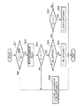
図2に示すように、遮断判定部22は、互いに対向する車両の両側部のうち、一方の側部に配置された右側部加速度センサ23Rを有する右側部処理部23と、他方の側部に配置された左側部加速度センサ24Lを有する左側部処理部24と、車両の前部に配置された前部加速度センサ25Fを有する前部処理部25と、車両の中央部に配置された中央部加速度センサ26Cを有する中央部処理部26とを備えて構成されている。
右側部処理部23及び左側部処理部24及び前部処理部25は、例えば同様の構成を有しており、各加速度センサ23R,24L,25Fから出力された加速度信号に基づいて衝突判定を行う各衝突判定部23a,24a,25aを備えている。
なお、右側部加速度センサ23R及び左側部加速度センサ24Lは、例えば車両の前後方向と交差する方向で車両に作用する加速度(或いは減速度)を検出し、前部加速度センサ25F及び中央部加速度センサ26Cは、例えば車両の前後方向に作用する加速度(或いは減速度)を検出して、検出された各加速度(或いは減速度)の大きさに応じた電圧レベルの加速度信号Gを出力する。
【0018】
中央部処理部26は、中央部加速度センサ26Cと、衝突判定部26aと、コンタクタ−水素遮断弁制御部26bと、点火回路26dとを備えて構成されている。
衝突判定部26aは、中央部加速度センサ26Cから出力される加速度信号G、及び、各衝突判定部23a,24a,25aから出力される判定結果の信号に基づいて衝突判定を行う。例えば各衝突判定部23a,24a,25aの何れかが衝突発生と判定した場合や、例えば中央部加速度センサ26Cにおいて所定の閾加速度を超える加速度が検出された場合等に、コンタクタ−水素遮断弁制御部26b及び点火回路26dへ衝突発生の信号を出力する。
【0019】
コンタクタ−水素遮断弁制御部26bは、衝突判定部26aから受信した衝突発生の信号に基づいて、各断続器19a,19b,19c及び水素遮断弁20の動作を制御する。
そして、後述するように、コンタクタ−水素遮断弁制御部26bは、燃料電池断続器19bと走行用モータ断続器19cによって電気的な接続が遮断されるタイミング、及び、水素遮断弁20によって水素ガスの供給が遮断されるタイミングに対して、例えば所定の遅延時間後に蓄電装置断続器19aを作動させる。
【0020】
点火回路26dは、衝突判定部26aでの判定結果に応じて、例えばエアバック装置等の乗員保護装置を作動させるための起動信号を発生する。例えば点火回路26dには、運転席及び助手席正突インフレータ27a,27bと運転席及び助手席側突インフレータ27c,27dとが接続されており、各インフレータ27a,…,27d内でスクイブによりガス発生剤に点火して、各インフレータ27a,…,27dからガスを発生させ、このガスによってエアバックを膨らませて乗員と室内部品との2次衝突を防止する。
【0021】
本実施の形態による燃料電池車両の燃料遮断装置10は上記構成を備えており、次に、この燃料電池車両の燃料遮断装置10の動作について説明する。
図4は燃料電池車両の燃料遮断装置10の動作、特に蓄電装置断続器19a及び水素遮断弁20の作動タイミングを決定する処理について示すフローチャートである。
先ず、図4に示すステップS01において、フェイル情報が検出されているか否かを判定する。
この判定結果が「YES」の場合には、ステップS02に進み、蓄電装置断続器19aにより蓄電装置12からの電力供給の遮断を指示するフラグF_CONT_SHTDWNのフラグ値に「0」をセットすると共に、水素遮断弁20の閉弁を指示するフラグF_H2_SHTDWNのフラグ値に「0」をセットして、一連の処理を終了する。
【0022】
一方、判定結果が「NO」の場合には、ステップS03に進み、各衝突判定部23a,24a,25a,26aにおいて、各加速度センサ23R,24L,25F,26Cから出力された加速度信号Gを読み込む。
そして、ステップS04においては、例えば各衝突判定部23a,24a,25a,26aの何れかにおいて、加速度信号Gが所定の第1閾加速度G1よりも大きいか否かを判定する。
この判定結果が「NO」の場合には、ステップS02以下の処理を行う。
一方、ステップS04での判定結果が「YES」の場合には、ステップS05に進み、水素遮断弁20の閉弁を指示するフラグF_H2_SHTDWNのフラグ値が「1」か否かを判定する。
【0023】
この判定結果が「NO」の場合には、ステップS06に進み、水素遮断弁20の閉弁を指示するフラグF_H2_SHTDWNのフラグ値に「1」をセットして一連の処理を終了する。
一方、ステップS05での判定結果が「YES」の場合には、ステップS07に進み、加速度信号Gが例えば第1閾加速度G1よりも大きな所定の第2閾加速度G2を超えているか否かを判定する。
この判定結果が「NO」の場合には、一連の処理を終了する。
一方、ステップS07での判定結果が「YES」の場合には、ステップS08に進み、蓄電装置12の遮断を指示するフラグF_CONT_SHTDWNのフラグ値に「1」をセットして、一連の処理を終了する。
【0024】
すなわち、車両の衝突発生時に加速度センサから出力される加速度信号Gに対して、加速度信号Gが相対的に小さな第1閾加速度G1を超えた場合、つまり衝突発生から相対的に短時間のうちに水素遮断弁20によって水素ガスの供給を遮断し、加速度信号Gが相対的に大きな第2閾加速度G2を超えた場合、つまり水素ガスの遮断から適宜の遅延時間後に蓄電装置断続器19aを作動させて、燃料電池駆動用補機類であるエアーコンプレサー17を停止させる。
これにより、例えば衝突発生直後に燃料電池断続器19bによって燃料電池11からの出力が遮断された場合であっても、燃料電池11の燃料極に供給された水素ガスが消費されて燃料極側の高圧状態が解消される。
【0025】
上述したように、本実施の形態による燃料電池車両の燃料遮断装置10によれば、例えば車両の衝突発生時に燃料電池11の出力が遮断された場合であっても、燃料電池11の燃料極に供給された水素ガスを消費して水素ガスの圧力を低下させることができ、燃料極と空気極との間に許容範囲を超える圧力のアンバランスが生じることを防止して、燃料電池11内の固体高分子電解質膜の変形や破損等が発生することを防ぐことができ、燃料電池11の寿命の延命化に資することができる。
【0026】
なお、本実施の形態においては、遮断判定部22における判定結果に応じて各断続器19a,19b,19c及び水素遮断弁20の動作を制御するとしたが、これに限定されず、例えば図5に示す本実施形態の燃料電池車両の燃料遮断装置10の第1変形例に係る遮断判定部32の構成図のように、遮断遅延処理部36cを備えても良い。
すなわち遮断遅延処理部36cは、燃料電池断続器19bと走行用モータ断続器19cによって電気的な接続が遮断され、水素遮断弁20によって水素ガスの供給が遮断された場合に、所定の遅延時間後に蓄電装置断続器19aを作動させる。
【0027】
さらに、本実施の形態においては、遮断判定部22における判定結果に応じて各断続器19a,19b,19c及び水素遮断弁20の動作を制御するとしたが、これに限定されず、例えば図6に示す本実施形態の第2変形例に係る燃料電池車両の燃料遮断装置40の構成図のように、複数のイナーシャスイッチによって各断続器19a,19b,19c及び水素遮断弁20の動作を制御しても良い。
ここで、各イナーシャスイッチ41a,41b,41cは磁性体からなる可動部と、この可動部を磁力により保持する保持部とを備えており、車両衝突時の衝撃により保持部の磁力を上回る衝撃が加わった場合に、保持部から開放された可動部が可動接点を押し上げるように変位させて導通を遮断するように構成されている。
【0028】
そして、イナーシャスイッチ41aは蓄電装置断続器19aを制御し、イナーシャスイッチ41bは燃料電池断続器19bを制御し、イナーシャスイッチ41cは水素遮断弁20を制御するように構成されている。
ここで、例えば蓄電装置断続器19aを制御するイナーシャスイッチ41aの保持部の磁力は、水素遮断弁20を制御するイナーシャスイッチ41cの保持部の磁力よりも大きく設定されており、車両衝突時には、先ず相対的に小さな衝撃が作用した時点で水素遮断弁20が閉弁され、この後、相対的に大きな衝撃が作用した際に蓄電装置断続器19aが作動してエアーコンプレッサー17等の燃料電池駆動用補機類への電力供給が停止される。
【0029】
なお、本実施形態においては、蓄電装置断続器19a及び燃料電池断続器19b及び走行用モータ断続器19cはコンタクタからなるとしたが、これに限定されず、各断続器19a,19b,19cは、例えば遮断器(ブレーカ)や内部の火薬を爆発させて導通部を遮断するフューズ等であっても良い。
【0030】
【発明の効果】
以上説明したように、請求項1に記載の本発明の燃料電池車両の燃料遮断装置によれば、燃料電池の極間圧力が大きく変動すること無しに両極での圧力を徐々に低下させることができ、固体高分子電解質膜の変形や破損等が生じることを防止して燃料電池の寿命の延命化に資することができる。
さらに、請求項2に記載の燃料電池車両の燃料遮断装置によれば、予め燃料供給遮断手段を作動させてから電源遮断手段を作動させるまでの遅延時間を、設定しておくことで、より一層確実に固体高分子電解質膜を保護することができる。
さらに、請求項3に記載の燃料電池車両の燃料遮断装置によれば、車両衝突時の衝撃の大きさに応じて燃料供給遮断手段及び電源遮断手段の作動を適切に制御することができる。
【図面の簡単な説明】
【図1】 本発明の一実施形態に係る燃料電池車両の燃料遮断装置の構成図である。
【図2】 本発明の一実施形態に係る燃料電池車両の燃料遮断装置の構成図である。
【図3】 図1に示す燃料供給部の要部構成図である。
【図4】 燃料電池車両の燃料遮断装置の動作、特に蓄電装置断続器及び水素遮断弁の作動タイミングを決定する処理について示すフローチャートである。
【図5】 図2に示す本実施形態の燃料電池車両の燃料遮断装置の第1変形例に係る遮断判定部の構成図である。
【図6】 本実施形態の第2変形例に係る燃料電池車両の燃料遮断装置の構成図である。
【符号の説明】
10 燃料電池車両の燃料遮断装置
11 燃料電池
12 蓄電装置
16 燃料供給部(燃料供給手段)
17 エアーコンプレッサー(補機駆動系)
19a 蓄電装置断続器(電源遮断手段)
20 水素遮断弁(燃料供給遮断手段)
21 遮断制御部(遮断制御手段)
23R,24L,25F,26C 加速度センサ(加速度検出手段)
36c 遮断遅延処理部(遅延手段)
ステップS04 第1判定手段
ステップS07 第2判定手段
ステップS06 燃料供給遮断制御手段
ステップS08 電源遮断制御手段[0001]
BACKGROUND OF THE INVENTION
The present invention relates to a fuel shut-off device for a fuel cell vehicle, and more particularly to a technique for shutting off a fuel supply that accompanies a stop of power supply to an auxiliary device for driving a fuel cell such as an air compressor.
[0002]
[Prior art]
Conventionally, a vehicle is driven by a power source supplied from a driving power source, for example, as in a power shut-off device for an electric vehicle disclosed in Japanese Patent Laid-Open No. 6-46502, for example, an abnormal approach to a vehicle collision or an obstacle, Alternatively, there is known a power shut-off device that cuts off the output of the drive power supply when a vehicle abnormality such as a leakage of the drive power supply is detected or when the possibility of occurrence of the abnormality is high.
In such a power shut-off device, for example, when a collision is detected by detecting a change in the acceleration of the vehicle based on an acceleration signal output from an acceleration sensor that detects acceleration (or deceleration) applied to the vehicle, a collision occurs. If determined, for example, the contact is opened at an output end of a power storage device such as a battery or at an appropriate position inside the battery.
As a result, the output terminal of the battery and the frame of the vehicle body come into contact with each other due to, for example, impact or vibration at the time of a collision, and a short circuit occurs. Is prevented from occurring.
[0003]
[Problems to be solved by the invention]
By the way, in the electric vehicle power shut-off device according to an example of the above-described prior art, when the driving power is shut off at the time of a vehicle collision or the like, the power supply to the fuel cell driving auxiliary equipment such as an air compressor is stopped. The
Here, when the operation of the air compressor is stopped, an appropriate time delay occurs after the power supply is stopped until the motor that actually drives the air compressor is stopped. For example, the reaction to the air electrode of the fuel cell Air continues to be supplied as gas as a signal pressure to the pressure control valve for fuel supply. Along with this, an amount of fuel (hydrogen gas) corresponding to the amount of air supplied is supplied to the fuel electrode of the fuel cell.
[0004]
At this time, if the output side of the fuel cell is cut off from an electric load such as a fuel cell driving auxiliary device such as a motor for driving an air compressor or a traveling motor, the output voltage of the fuel cell is zero. It rises to a load state (for example, OCV: Open Circuit Voltage).
That is, since the output from the fuel cell is not taken out, the open circuit voltage is continuously output, and the air compressor is stopped, and when the air pressure eventually decreases to the atmospheric pressure state, the fuel in the fuel cell, that is, The consumption of hydrogen gas is reduced and the high pressure state of hydrogen gas is maintained.
Then, an unbalance exceeding the allowable range occurs in the interpolar pressure (between the air electrode and the fuel electrode) of the solid polymer membrane type fuel cell, and the solid polymer electrolyte membrane in the fuel cell is deformed or damaged. There is a fear.
The present invention has been made in view of the above circumstances, and when the power supply to the fuel cell driving accessories is interrupted, the unbalance exceeding the allowable range in the pressure between the air and the fuel supplied to the fuel cell is exceeded. An object of the present invention is to provide a fuel shut-off device for a fuel cell vehicle that can prevent the occurrence of the occurrence of the fuel cell and prevent the fuel cell from being deteriorated or damaged.
[0005]
[Means for Solving the Problems]
In order to solve the above problems and achieve the object, a fuel shut-off device for a fuel cell vehicle according to a first aspect of the present invention includes a fuel cell power generation system (for example, the
[0006]
According to the fuel shut-off device for a fuel cell vehicle having the above-described configuration, for example, when a vehicle collision occurs, first, power supply from the fuel cell to a load such as a travel motor is shut off, and the fuel to the fuel electrode of the fuel cell Supply, that is, supply of hydrogen gas is stopped.
At this time, the pressure of hydrogen gas is high in the fuel electrode of the fuel cell. For example, air is supplied from the fuel cell driving means such as an air compressor to the air electrode of the fuel cell. The pressure between the electrodes of the solid polymer electrolyte membrane is maintained within a predetermined allowable range, and hydrogen gas is consumed at the fuel electrode, and the pressure on the fuel electrode side is gradually reduced.
And by stopping the power supply from the power storage device to the fuel cell driving means at an appropriate timing, the pressure of the air on the air electrode side can be lowered so as to follow the pressure drop on the fuel electrode side, The pressure at both poles can be gradually reduced without the inter-pole pressure fluctuating greatly.
Thereby, for example, deformation or breakage of the solid polymer electrolyte membrane is prevented, which can contribute to the extension of the life of the fuel cell.
[0007]
Further, in the fuel shut-off device for a fuel cell vehicle according to the second aspect of the present invention, the shut-off control means delays the power shut-off means by delaying a predetermined time after actuating the fuel supply shut-off means. Means (for example, an interruption
According to the fuel shut-off device for a fuel cell vehicle having the above-described configuration, the delay time from when the fuel supply shut-off means is actuated until the power shut-off means is actuated in advance, for example, the size of a pipe or manifold of hydrogen gas, The solid polymer electrolyte membrane can be more reliably protected by setting based on the power consumption of the fuel cell driving means such as an air compressor.
[0008]
Furthermore, in the fuel shutoff device for a fuel cell vehicle according to the third aspect of the present invention, the shutoff control means is configured such that the acceleration is a predetermined first threshold acceleration (for example, a first threshold acceleration G1 in an embodiment described later). ) Exceeds the first threshold acceleration (for example, which will be described later), and first determination means for determining whether the acceleration exceeds the first threshold acceleration (for example, step S04 in the embodiment described later). Second determination means for determining whether or not the second threshold acceleration G2) in the embodiment has been exceeded (for example, step S07 in the embodiment to be described later), and depending on the determination result by the first determination means, Fuel supply cutoff control means for operating the fuel supply cutoff means (for example, step S06 in the embodiment described later), and power cutoff control for operating the power cutoff means according to the determination result by the second determination means Stage (e.g., step S08 in the embodiment described below) is characterized in that a.
[0009]
According to the fuel shut-off device for a fuel cell vehicle having the above-described configuration, it is possible to appropriately control the operation of the fuel supply shut-off means and the power shut-off means according to the magnitude of impact at the time of the vehicle collision. As a result, the pressure between the electrodes of the fuel cell can be controlled in detail according to the collision state, and the solid polymer electrolyte membrane can be more reliably protected.
[0010]
DETAILED DESCRIPTION OF THE INVENTION
Hereinafter, an embodiment of a fuel cutoff device for a fuel cell vehicle according to the present invention will be described with reference to the accompanying drawings. 1 and 2 are block diagrams of a fuel cutoff device 10 for a fuel cell vehicle according to an embodiment of the present invention, and FIG. 3 is a block diagram of the main part of the
A fuel shut-off device 10 for a fuel cell vehicle according to the present embodiment includes a hybrid power supply device composed of, for example, a
[0011]
As shown in FIG. 1, a fuel cutoff device 10 of a fuel cell vehicle includes a
[0012]
The traveling
The
The
[0013]
The
As shown in FIG. 3, the
[0014]
The hydrogen gas supplied from the pressure
The fuel discharge port of the
[0015]
The
In addition, fuel cell driving accessories such as an
The DC power output from the
[0016]
A power
In addition, a
[0017]
As shown in FIG. 2, the blocking
The right
The right
[0018]
The
The
[0019]
The contactor-hydrogen cutoff
Then, as will be described later, the contactor-hydrogen cutoff
[0020]
The
[0021]
The fuel cutoff device 10 of the fuel cell vehicle according to the present embodiment has the above-described configuration. Next, the operation of the fuel cutoff device 10 of the fuel cell vehicle will be described.
FIG. 4 is a flowchart showing the operation of the fuel cutoff device 10 of the fuel cell vehicle, particularly the processing for determining the operation timing of the power
First, in step S01 shown in FIG. 4, it is determined whether or not fail information is detected.
If this determination is “YES”, the flow proceeds to step S 02, where “0” is set to the flag value of the flag F_CONT_SHTDWN that instructs the power
[0022]
On the other hand, if the determination result is “NO”, the process proceeds to step S03, and the
In step S04, for example, in any of the
If this determination is “NO”, the processing in step S 02 and subsequent steps is performed.
On the other hand, if the determination result in step S04 is “YES”, the process proceeds to step S05, and it is determined whether or not the flag value of the flag F_H2_SHTDWN for instructing closing of the
[0023]
If this determination is “NO”, the flow proceeds to step S 06, “1” is set to the flag value of the flag F_H 2 _SHTDWN instructing the valve closing of the
On the other hand, if the determination result in step S05 is “YES”, the process proceeds to step S07 to determine whether or not the acceleration signal G exceeds a predetermined second threshold acceleration G2 that is greater than the first threshold acceleration G1, for example. To do.
When the determination result is “NO”, the series of processes is terminated.
On the other hand, if the determination result in step S07 is “YES”, the process proceeds to step S08, where “1” is set to the flag value of the flag F_CONT_SHTDWN for instructing to shut off the
[0024]
That is, when the acceleration signal G exceeds the relatively small first threshold acceleration G1 with respect to the acceleration signal G output from the acceleration sensor when the vehicle collision occurs, that is, within a relatively short time from the occurrence of the collision. When the supply of hydrogen gas is shut off by the hydrogen shut-off
Thereby, for example, even when the output from the
[0025]
As described above, according to the fuel cutoff device 10 of the fuel cell vehicle according to the present embodiment, even when the output of the
[0026]
In the present embodiment, the operation of each of the
In other words, the shutoff
[0027]
Furthermore, in the present embodiment, the operation of each of the
Here, each
[0028]
The
Here, for example, the magnetic force of the holding part of the
[0029]
In the present embodiment, the power
[0030]
【The invention's effect】
As described above, according to the fuel cutoff device for a fuel cell vehicle of the present invention described in
Furthermore, according to the fuel shut-off device for a fuel cell vehicle according to claim 2, the delay time from when the fuel supply shut-off means is actuated until when the power shut-off means is actuated is further set. The solid polymer electrolyte membrane can be reliably protected.
Furthermore, according to the fuel shut-off device for a fuel cell vehicle according to claim 3, the operation of the fuel supply shut-off means and the power shut-off means can be appropriately controlled according to the magnitude of the impact at the time of the vehicle collision.
[Brief description of the drawings]
FIG. 1 is a configuration diagram of a fuel cutoff device for a fuel cell vehicle according to an embodiment of the present invention.
FIG. 2 is a configuration diagram of a fuel cutoff device for a fuel cell vehicle according to an embodiment of the present invention.
FIG. 3 is a main part configuration diagram of a fuel supply unit shown in FIG. 1;
FIG. 4 is a flowchart showing the operation of the fuel cutoff device of the fuel cell vehicle, particularly the processing for determining the operation timing of the power storage device interrupter and the hydrogen cutoff valve.
FIG. 5 is a configuration diagram of a cutoff determination unit according to a first modification of the fuel cutoff device of the fuel cell vehicle of the present embodiment shown in FIG. 2;
FIG. 6 is a configuration diagram of a fuel cutoff device for a fuel cell vehicle according to a second modification of the present embodiment.
[Explanation of symbols]
DESCRIPTION OF SYMBOLS 10
17 Air compressor (auxiliary drive system)
19a Power storage device interrupter (power cutoff means)
20 Hydrogen cutoff valve (fuel supply cutoff means)
21 Blocking control unit (blocking control means)
23R, 24L, 25F, 26C Acceleration sensor (acceleration detection means)
36c Blocking delay processing unit (delay means)
Step S04 First determination means Step S07 Second determination means Step S06 Fuel supply cutoff control means Step S08 Power cutoff control means
Claims (3)
前記燃料電池車両に作用する加速度を検出する加速度検出手段と、
前記燃料電池車両の走行系、及び/又は、前記燃料電池発電システムの補機駆動系の電源ラインを遮断する電源遮断手段と、
前記燃料電池発電システムの燃料電池へ供給される燃料供給手段からの燃料供給を遮断する燃料供給遮断手段と、
前記加速度検出手段にて検出された前記加速度に基づいて、前記燃料供給遮断手段を作動させた後に前記電源遮断手段を作動させる遮断制御手段と
を備えたことを特徴とする燃料電池車両の燃料遮断装置。In a fuel cell vehicle powered by a fuel cell power generation system,
Acceleration detecting means for detecting acceleration acting on the fuel cell vehicle;
A power shut-off means for shutting off the power line of the traveling system of the fuel cell vehicle and / or the auxiliary drive system of the fuel cell power generation system;
Fuel supply shut-off means for shutting off the fuel supply from the fuel supply means supplied to the fuel cell of the fuel cell power generation system;
A fuel cutoff for a fuel cell vehicle, comprising: a cutoff control means for actuating the power cutoff means after actuating the fuel supply cutoff means based on the acceleration detected by the acceleration detection means apparatus.
前記第1判定手段による判定結果に応じて前記燃料供給遮断手段を作動させる燃料供給遮断制御手段と、前記第2判定手段による判定結果に応じて前記電源遮断手段を作動させる電力供給遮断制御手段と
を備えたことを特徴とする請求項1に記載の燃料電池車両の燃料遮断装置。The blocking control means includes first determination means for determining whether or not the acceleration exceeds a predetermined first threshold acceleration, and whether or not the acceleration exceeds a predetermined second threshold acceleration larger than the first threshold acceleration. Second determination means for determining whether or not
Fuel supply cutoff control means for operating the fuel supply cutoff means according to the determination result by the first determination means, and power supply cutoff control means for operating the power cutoff means according to the determination result by the second determination means; The fuel cutoff device for a fuel cell vehicle according to claim 1, comprising:
Priority Applications (4)
| Application Number | Priority Date | Filing Date | Title |
|---|---|---|---|
| JP2000176031A JP4271347B2 (en) | 2000-06-12 | 2000-06-12 | Fuel shut-off device for fuel cell vehicle |
| US09/870,744 US6591924B2 (en) | 2000-06-12 | 2001-06-01 | Method and apparatus for cutting off fuel of a fuel cell vehicle |
| DE60134084T DE60134084D1 (en) | 2000-06-12 | 2001-06-08 | Method and device for interrupting the fuel supply of a vehicle with fuel cells |
| EP01114009A EP1164048B1 (en) | 2000-06-12 | 2001-06-08 | Method and apparatus for cutting off fuel supply of a fuel cell vehicle |
Applications Claiming Priority (1)
| Application Number | Priority Date | Filing Date | Title |
|---|---|---|---|
| JP2000176031A JP4271347B2 (en) | 2000-06-12 | 2000-06-12 | Fuel shut-off device for fuel cell vehicle |
Publications (2)
| Publication Number | Publication Date |
|---|---|
| JP2001357863A JP2001357863A (en) | 2001-12-26 |
| JP4271347B2 true JP4271347B2 (en) | 2009-06-03 |
Family
ID=18677808
Family Applications (1)
| Application Number | Title | Priority Date | Filing Date |
|---|---|---|---|
| JP2000176031A Expired - Fee Related JP4271347B2 (en) | 2000-06-12 | 2000-06-12 | Fuel shut-off device for fuel cell vehicle |
Country Status (4)
| Country | Link |
|---|---|
| US (1) | US6591924B2 (en) |
| EP (1) | EP1164048B1 (en) |
| JP (1) | JP4271347B2 (en) |
| DE (1) | DE60134084D1 (en) |
Families Citing this family (48)
| Publication number | Priority date | Publication date | Assignee | Title |
|---|---|---|---|---|
| US6860357B2 (en) * | 2001-05-18 | 2005-03-01 | Mitsubishi Jidosha Kogyo Kabushiki Kaisha | Motor vehicle that acquires driving power for running from high voltage power supply |
| JP3730592B2 (en) * | 2001-06-06 | 2006-01-05 | 本田技研工業株式会社 | Control device for fuel cell vehicle |
| JP4032723B2 (en) * | 2001-12-06 | 2008-01-16 | 松下電器産業株式会社 | Air conditioner |
| JP2003217631A (en) * | 2002-01-17 | 2003-07-31 | Nissan Motor Co Ltd | Fuel cell control device |
| JP3826833B2 (en) * | 2002-04-19 | 2006-09-27 | トヨタ自動車株式会社 | Fuel cell system and control method thereof |
| EP1416561B1 (en) * | 2002-10-31 | 2008-05-21 | Matsushita Electric Industrial Co., Ltd. | Method of operation fuel cell system and fuel cell system |
| JP4147939B2 (en) * | 2002-12-26 | 2008-09-10 | 日産自動車株式会社 | Vehicle with fuel cell |
| JP4066882B2 (en) * | 2003-05-22 | 2008-03-26 | トヨタ自動車株式会社 | Control device and control method for in-vehicle fuel cell power generation system |
| US7308959B2 (en) * | 2003-09-15 | 2007-12-18 | General Motors Corporation | Displacement on demand with regenerative braking |
| DE10361647A1 (en) * | 2003-12-30 | 2005-08-04 | General Motors Corp., Detroit | Vehicle safety system for use in a vehicle with a fuel cell system and an electric power source where the fuel cell system is connected to the air bag control |
| US20100000434A1 (en) * | 2004-01-23 | 2010-01-07 | Pristash David J | Micro fuel cell with membrane storage |
| GB2424991B (en) * | 2004-02-12 | 2007-10-17 | Avl List Gmbh | Device & Method For Determining The Operating Parameters Of Individual Cells Or Short Stacks Of Fuel Cells |
| US7350604B2 (en) * | 2004-03-04 | 2008-04-01 | Ford Global Technologies, Llc | Gaseous fuel system for automotive vehicle |
| DE102004034071A1 (en) * | 2004-07-15 | 2006-02-09 | Daimlerchrysler Ag | Shutdown procedure for fuel cell systems |
| JP4549826B2 (en) * | 2004-11-26 | 2010-09-22 | 本田技研工業株式会社 | Fuel cell vehicle |
| JP2006182300A (en) | 2004-12-28 | 2006-07-13 | Denso Corp | Collision safety system for vehicle |
| AU2006270218A1 (en) * | 2005-07-18 | 2007-01-25 | Societe Bic | Separable fuel cartridge |
| JP4982060B2 (en) * | 2005-08-25 | 2012-07-25 | クラリオン株式会社 | In-vehicle system for fuel cell vehicles |
| CN1992404B (en) * | 2005-12-28 | 2011-08-17 | 雅马哈发动机株式会社 | Fuel cell system and operating method thereof |
| JP5120910B2 (en) * | 2006-03-15 | 2013-01-16 | 学校法人金井学園 | Launch control device |
| JP4856456B2 (en) * | 2006-03-22 | 2012-01-18 | 本田技研工業株式会社 | Electric vehicle |
| KR100837958B1 (en) | 2006-12-11 | 2008-06-16 | 현대자동차주식회사 | Hydrogen Exhaust Control Method and System |
| DE102007029715A1 (en) * | 2007-06-27 | 2009-01-08 | Daimler Ag | Safety device for a vehicle operated with a fuel cell system and vehicle with the safety device |
| JP4946684B2 (en) | 2007-07-13 | 2012-06-06 | トヨタ自動車株式会社 | Moving body |
| JP2009090685A (en) * | 2007-10-03 | 2009-04-30 | Toyota Industries Corp | Industrial vehicle hood interlock device |
| KR100986500B1 (en) * | 2008-10-28 | 2010-10-08 | 현대자동차주식회사 | Multi-Stack Fuel Cell Hybrid System |
| JP5477101B2 (en) * | 2010-03-24 | 2014-04-23 | トヨタ自動車株式会社 | Fuel cell vehicle |
| WO2011143191A1 (en) * | 2010-05-13 | 2011-11-17 | Coda Automotive, Inc. | Battery disconnection in electric vehicles |
| JP5355631B2 (en) * | 2011-07-07 | 2013-11-27 | 本田技研工業株式会社 | Control method for fuel cell vehicle |
| JP5772712B2 (en) * | 2012-05-14 | 2015-09-02 | 株式会社デンソー | Vehicle equipment |
| JP2012212687A (en) * | 2012-07-05 | 2012-11-01 | Toshiba Home Technology Corp | Fuel cell device |
| JP6119662B2 (en) * | 2014-04-22 | 2017-04-26 | トヨタ自動車株式会社 | Electric vehicle |
| KR20150138762A (en) | 2014-06-02 | 2015-12-10 | 현대자동차주식회사 | Safety system of fuel cell vehicle and control method for the same |
| CN105383322A (en) * | 2015-12-21 | 2016-03-09 | 钟馨稼 | Hydrogen-energy pure electric power assembly |
| DE102017211474A1 (en) * | 2017-07-05 | 2019-01-10 | Bayerische Motoren Werke Aktiengesellschaft | Method for relieving pressure from at least one pressure vessel and pressure vessel system |
| JP6554151B2 (en) * | 2017-08-31 | 2019-07-31 | 本田技研工業株式会社 | Vehicle power system |
| JP6545230B2 (en) * | 2017-08-31 | 2019-07-17 | 本田技研工業株式会社 | Vehicle power system |
| CN107816630B (en) * | 2017-10-21 | 2021-03-02 | 江苏国富氢能技术装备股份有限公司 | Hydrogenation machine with three-axis acceleration sensor and control method thereof |
| AU2019330769B2 (en) * | 2018-08-30 | 2023-01-05 | Watt Fuel Cell Corp. | Safety control system and method for fuel-consuming apparatus |
| CN110370989A (en) * | 2019-06-26 | 2019-10-25 | 武汉格罗夫氢能汽车有限公司 | Electricity strategy under a kind of fuel cell car high pressure |
| CN111038288B (en) * | 2019-12-25 | 2021-04-06 | 上汽大众汽车有限公司 | Control system and method for vehicle hydrogen charging |
| DE102020120493A1 (en) | 2020-08-04 | 2022-02-10 | Bayerische Motoren Werke Aktiengesellschaft | Pressure vessel arrangement, fuel supply device and motor vehicle |
| CN112234056B (en) * | 2020-09-03 | 2024-04-09 | 深圳市汇德科技有限公司 | Semiconductor device |
| CN114179615B (en) * | 2020-09-15 | 2023-09-01 | 宇通客车股份有限公司 | Collision processing control method and system for fuel cell vehicle |
| DE102021201176A1 (en) * | 2021-02-09 | 2022-08-11 | Robert Bosch Gesellschaft mit beschränkter Haftung | Tank device for storing a gaseous medium for a vehicle and method for operating a tank device for storing a gaseous medium for a vehicle |
| CN114180077B (en) * | 2021-12-21 | 2024-02-27 | 中国航发沈阳发动机研究所 | Self-adaptive adjustment method for accelerating oil supply rule of aero-engine |
| CN115095430B (en) * | 2022-06-27 | 2023-10-20 | 潍柴动力股份有限公司 | Control method and device for hydrogen fuel automobile, hydrogen fuel automobile and storage medium |
| DE102023208587A1 (en) * | 2023-09-06 | 2025-03-06 | Robert Bosch Gesellschaft mit beschränkter Haftung | Fuel cell system, trailer and method for increasing the safety of a fuel cell system in a trailer |
Family Cites Families (23)
| Publication number | Priority date | Publication date | Assignee | Title |
|---|---|---|---|---|
| US3743849A (en) * | 1970-09-21 | 1973-07-03 | Mitsubadenkiseisakusho Co Ltd | Apparatus for automatically disconnecting power circuit for vehicles due to impact |
| US4001185A (en) * | 1972-06-28 | 1977-01-04 | Matsushita Electric Industrial Co., Ltd. | Acceleration sensing device |
| JPH0622156B2 (en) * | 1985-03-01 | 1994-03-23 | 三菱電機株式会社 | Fuel cell device |
| JPS63159147A (en) * | 1986-12-22 | 1988-07-02 | Ishikawajima Harima Heavy Ind Co Ltd | Fuel cut-off device for automobile |
| US5483447A (en) * | 1988-09-17 | 1996-01-09 | Robert Bosch Gmbh | Apparatus for tripping a system for the protection of occupants of a vehicle |
| US5327990A (en) * | 1989-05-16 | 1994-07-12 | Busquets Albert B | Integral automatic system for protection and rescue of occupants in crashed automobiles |
| US5248566A (en) * | 1991-11-25 | 1993-09-28 | The United States Of America As Represented By The United States Department Of Energy | Fuel cell system for transportation applications |
| JP3480501B2 (en) | 1992-03-17 | 2003-12-22 | 株式会社エクォス・リサーチ | Power cut-off device for electric vehicles |
| US5389824A (en) * | 1992-03-17 | 1995-02-14 | Kabushiki Kaisha Equos Research | Power supply cut off apparatus |
| US5346778A (en) * | 1992-08-13 | 1994-09-13 | Energy Partners, Inc. | Electrochemical load management system for transportation applications |
| DE4323604C2 (en) * | 1993-07-09 | 2001-12-06 | Mannesmann Sachs Ag | Vehicle with at least one electric motor |
| IL107930A0 (en) * | 1993-12-07 | 1994-04-12 | Electric Fuel Ltd | A metal-air battery-powered electric vehicle |
| US6116363A (en) * | 1995-05-31 | 2000-09-12 | Frank Transportation Technology, Llc | Fuel consumption control for charge depletion hybrid electric vehicles |
| US5771476A (en) * | 1995-12-29 | 1998-06-23 | Dbb Fuel Cell Engines Gmbh | Power control system for a fuel cell powered vehicle |
| US5791366A (en) * | 1996-01-16 | 1998-08-11 | Preece Incorporated | Frangible quick disconnect coupling |
| US5900330A (en) * | 1997-09-25 | 1999-05-04 | Kagatani; Takeo | Power device |
| GB9722124D0 (en) * | 1997-10-20 | 1997-12-17 | European Community | A reactor |
| US6459231B1 (en) * | 1999-05-03 | 2002-10-01 | Takeo Kagatani | Power device |
| JP4253920B2 (en) * | 1999-05-06 | 2009-04-15 | 日産自動車株式会社 | Fuel cell vehicle power distribution control device |
| US6354261B1 (en) * | 1999-11-05 | 2002-03-12 | Arthur Thomas Lassiter | Impact sensitive fuel control system |
| US6393354B1 (en) * | 2000-12-13 | 2002-05-21 | Utc Fuel Cells, Llc | Predictive control arrangement for load-following fuel cell-powered applications |
| US6488345B1 (en) * | 2001-08-16 | 2002-12-03 | General Motors Corporation | Regenerative braking system for a batteriless fuel cell vehicle |
| US6502533B1 (en) * | 2001-09-29 | 2003-01-07 | George Beuan Kirby Meacham | Internal combustion fuel reforming |
-
2000
- 2000-06-12 JP JP2000176031A patent/JP4271347B2/en not_active Expired - Fee Related
-
2001
- 2001-06-01 US US09/870,744 patent/US6591924B2/en not_active Expired - Lifetime
- 2001-06-08 DE DE60134084T patent/DE60134084D1/en not_active Expired - Lifetime
- 2001-06-08 EP EP01114009A patent/EP1164048B1/en not_active Expired - Lifetime
Also Published As
| Publication number | Publication date |
|---|---|
| US20010050189A1 (en) | 2001-12-13 |
| EP1164048B1 (en) | 2008-05-21 |
| DE60134084D1 (en) | 2008-07-03 |
| JP2001357863A (en) | 2001-12-26 |
| US6591924B2 (en) | 2003-07-15 |
| EP1164048A2 (en) | 2001-12-19 |
| EP1164048A3 (en) | 2005-05-11 |
Similar Documents
| Publication | Publication Date | Title |
|---|---|---|
| JP4271347B2 (en) | Fuel shut-off device for fuel cell vehicle | |
| US7690458B2 (en) | Control apparatus and control method for vehicle-mounted fuel cell power generation system | |
| JP4545285B2 (en) | Fuel cell vehicle start control device | |
| JP3842015B2 (en) | Idle control device for fuel cell vehicle | |
| JP3816436B2 (en) | Control device for fuel cell vehicle | |
| JP2007259537A (en) | Electric vehicle | |
| JP3946623B2 (en) | Control device for fuel cell vehicle | |
| JP4554151B2 (en) | Control device for fuel cell vehicle | |
| JP3863092B2 (en) | In-vehicle motor regeneration control device | |
| JP4746593B2 (en) | Contactor connection / disconnection method | |
| JP4847929B2 (en) | Contactor failure detection method and apparatus in fuel cell system | |
| JP3839397B2 (en) | Device for detecting disconnection of voltage detection line of power storage device | |
| JP2017147782A (en) | Secondary battery disconnection method | |
| JP4064213B2 (en) | Method and apparatus for discharging fuel cell stack | |
| JP6218181B2 (en) | Switch failure detection method for fuel cell system | |
| JP2007335184A (en) | Fuel cell vehicle | |
| JP3732736B2 (en) | Vehicle control system | |
| JP2003157870A (en) | Power supply system and power supply system control method | |
| JP4173356B2 (en) | Starting method of fuel cell system | |
| JP2011228076A (en) | Fuel cell system | |
| JP4451056B2 (en) | Control device for fuel cell vehicle | |
| JP5038874B2 (en) | Contactor control system | |
| JP4056863B2 (en) | Fault detection device for voltage detection circuit | |
| JP7545245B2 (en) | Power Control System | |
| JP2007151346A (en) | Moving body |
Legal Events
| Date | Code | Title | Description |
|---|---|---|---|
| A621 | Written request for application examination |
Free format text: JAPANESE INTERMEDIATE CODE: A621 Effective date: 20061201 |
|
| TRDD | Decision of grant or rejection written | ||
| A01 | Written decision to grant a patent or to grant a registration (utility model) |
Free format text: JAPANESE INTERMEDIATE CODE: A01 Effective date: 20090217 |
|
| A01 | Written decision to grant a patent or to grant a registration (utility model) |
Free format text: JAPANESE INTERMEDIATE CODE: A01 |
|
| A61 | First payment of annual fees (during grant procedure) |
Free format text: JAPANESE INTERMEDIATE CODE: A61 Effective date: 20090225 |
|
| FPAY | Renewal fee payment (event date is renewal date of database) |
Free format text: PAYMENT UNTIL: 20120306 Year of fee payment: 3 |
|
| R150 | Certificate of patent or registration of utility model |
Ref document number: 4271347 Country of ref document: JP Free format text: JAPANESE INTERMEDIATE CODE: R150 Free format text: JAPANESE INTERMEDIATE CODE: R150 |
|
| FPAY | Renewal fee payment (event date is renewal date of database) |
Free format text: PAYMENT UNTIL: 20120306 Year of fee payment: 3 |
|
| FPAY | Renewal fee payment (event date is renewal date of database) |
Free format text: PAYMENT UNTIL: 20130306 Year of fee payment: 4 |
|
| FPAY | Renewal fee payment (event date is renewal date of database) |
Free format text: PAYMENT UNTIL: 20130306 Year of fee payment: 4 |
|
| FPAY | Renewal fee payment (event date is renewal date of database) |
Free format text: PAYMENT UNTIL: 20140306 Year of fee payment: 5 |
|
| LAPS | Cancellation because of no payment of annual fees |