JP4270437B2 - Forceps with a bendable shaft - Google Patents
Forceps with a bendable shaft Download PDFInfo
- Publication number
- JP4270437B2 JP4270437B2 JP2002584779A JP2002584779A JP4270437B2 JP 4270437 B2 JP4270437 B2 JP 4270437B2 JP 2002584779 A JP2002584779 A JP 2002584779A JP 2002584779 A JP2002584779 A JP 2002584779A JP 4270437 B2 JP4270437 B2 JP 4270437B2
- Authority
- JP
- Japan
- Prior art keywords
- forceps
- shaft
- assembly
- cable
- tube
- Prior art date
- Legal status (The legal status is an assumption and is not a legal conclusion. Google has not performed a legal analysis and makes no representation as to the accuracy of the status listed.)
- Expired - Lifetime
Links
- 239000011324 bead Substances 0.000 claims abstract description 34
- 230000005540 biological transmission Effects 0.000 claims description 16
- 230000007246 mechanism Effects 0.000 claims description 9
- 239000011248 coating agent Substances 0.000 claims description 8
- 238000000576 coating method Methods 0.000 claims description 8
- 230000007423 decrease Effects 0.000 claims description 3
- 244000261422 Lysimachia clethroides Species 0.000 claims description 2
- 229910052751 metal Inorganic materials 0.000 claims description 2
- 239000002184 metal Substances 0.000 claims description 2
- 230000008878 coupling Effects 0.000 claims 1
- 238000010168 coupling process Methods 0.000 claims 1
- 238000005859 coupling reaction Methods 0.000 claims 1
- 210000004204 blood vessel Anatomy 0.000 description 15
- 238000007373 indentation Methods 0.000 description 6
- 239000000463 material Substances 0.000 description 6
- 230000000717 retained effect Effects 0.000 description 6
- 239000004033 plastic Substances 0.000 description 5
- 229910001220 stainless steel Inorganic materials 0.000 description 5
- 239000010935 stainless steel Substances 0.000 description 5
- 238000001356 surgical procedure Methods 0.000 description 5
- 229920006362 Teflon® Polymers 0.000 description 4
- 230000002829 reductive effect Effects 0.000 description 4
- 239000004809 Teflon Substances 0.000 description 3
- 239000007787 solid Substances 0.000 description 3
- 230000006835 compression Effects 0.000 description 2
- 238000007906 compression Methods 0.000 description 2
- 230000003247 decreasing effect Effects 0.000 description 2
- 230000000670 limiting effect Effects 0.000 description 2
- 238000000034 method Methods 0.000 description 2
- 238000002324 minimally invasive surgery Methods 0.000 description 2
- 238000012986 modification Methods 0.000 description 2
- 230000004048 modification Effects 0.000 description 2
- 238000003466 welding Methods 0.000 description 2
- 229910001200 Ferrotitanium Inorganic materials 0.000 description 1
- RTAQQCXQSZGOHL-UHFFFAOYSA-N Titanium Chemical compound [Ti] RTAQQCXQSZGOHL-UHFFFAOYSA-N 0.000 description 1
- 239000000853 adhesive Substances 0.000 description 1
- 238000004026 adhesive bonding Methods 0.000 description 1
- 230000001070 adhesive effect Effects 0.000 description 1
- 229910052782 aluminium Inorganic materials 0.000 description 1
- XAGFODPZIPBFFR-UHFFFAOYSA-N aluminium Chemical compound [Al] XAGFODPZIPBFFR-UHFFFAOYSA-N 0.000 description 1
- 230000000712 assembly Effects 0.000 description 1
- 238000000429 assembly Methods 0.000 description 1
- 230000000295 complement effect Effects 0.000 description 1
- 238000002788 crimping Methods 0.000 description 1
- 230000000694 effects Effects 0.000 description 1
- 238000002674 endoscopic surgery Methods 0.000 description 1
- 230000002452 interceptive effect Effects 0.000 description 1
- 238000002350 laparotomy Methods 0.000 description 1
- 238000003754 machining Methods 0.000 description 1
- 230000036961 partial effect Effects 0.000 description 1
- 230000001737 promoting effect Effects 0.000 description 1
- 239000010936 titanium Substances 0.000 description 1
- WFKWXMTUELFFGS-UHFFFAOYSA-N tungsten Chemical compound [W] WFKWXMTUELFFGS-UHFFFAOYSA-N 0.000 description 1
- 229910052721 tungsten Inorganic materials 0.000 description 1
- 239000010937 tungsten Substances 0.000 description 1
Images


Classifications
-
- A—HUMAN NECESSITIES
- A61—MEDICAL OR VETERINARY SCIENCE; HYGIENE
- A61B—DIAGNOSIS; SURGERY; IDENTIFICATION
- A61B17/00—Surgical instruments, devices or methods
- A61B17/12—Surgical instruments, devices or methods for ligaturing or otherwise compressing tubular parts of the body, e.g. blood vessels or umbilical cord
- A61B17/122—Clamps or clips, e.g. for the umbilical cord
-
- A—HUMAN NECESSITIES
- A61—MEDICAL OR VETERINARY SCIENCE; HYGIENE
- A61B—DIAGNOSIS; SURGERY; IDENTIFICATION
- A61B17/00—Surgical instruments, devices or methods
- A61B17/00234—Surgical instruments, devices or methods for minimally invasive surgery
- A61B2017/00292—Surgical instruments, devices or methods for minimally invasive surgery mounted on or guided by flexible, e.g. catheter-like, means
-
- A—HUMAN NECESSITIES
- A61—MEDICAL OR VETERINARY SCIENCE; HYGIENE
- A61B—DIAGNOSIS; SURGERY; IDENTIFICATION
- A61B17/00—Surgical instruments, devices or methods
- A61B17/28—Surgical forceps
- A61B17/2812—Surgical forceps with a single pivotal connection
- A61B17/2833—Locking means
- A61B2017/2837—Locking means with a locking ratchet
-
- A—HUMAN NECESSITIES
- A61—MEDICAL OR VETERINARY SCIENCE; HYGIENE
- A61B—DIAGNOSIS; SURGERY; IDENTIFICATION
- A61B17/00—Surgical instruments, devices or methods
- A61B17/28—Surgical forceps
- A61B17/29—Forceps for use in minimally invasive surgery
- A61B2017/2901—Details of shaft
-
- A—HUMAN NECESSITIES
- A61—MEDICAL OR VETERINARY SCIENCE; HYGIENE
- A61B—DIAGNOSIS; SURGERY; IDENTIFICATION
- A61B17/00—Surgical instruments, devices or methods
- A61B17/28—Surgical forceps
- A61B17/29—Forceps for use in minimally invasive surgery
- A61B2017/2901—Details of shaft
- A61B2017/2905—Details of shaft flexible
-
- A—HUMAN NECESSITIES
- A61—MEDICAL OR VETERINARY SCIENCE; HYGIENE
- A61B—DIAGNOSIS; SURGERY; IDENTIFICATION
- A61B17/00—Surgical instruments, devices or methods
- A61B17/28—Surgical forceps
- A61B17/29—Forceps for use in minimally invasive surgery
- A61B2017/2946—Locking means
-
- A—HUMAN NECESSITIES
- A61—MEDICAL OR VETERINARY SCIENCE; HYGIENE
- A61B—DIAGNOSIS; SURGERY; IDENTIFICATION
- A61B90/00—Instruments, implements or accessories specially adapted for surgery or diagnosis and not covered by any of the groups A61B1/00 - A61B50/00, e.g. for luxation treatment or for protecting wound edges
- A61B90/50—Supports for surgical instruments, e.g. articulated arms
- A61B2090/508—Supports for surgical instruments, e.g. articulated arms with releasable brake mechanisms
-
- A—HUMAN NECESSITIES
- A61—MEDICAL OR VETERINARY SCIENCE; HYGIENE
- A61B—DIAGNOSIS; SURGERY; IDENTIFICATION
- A61B90/00—Instruments, implements or accessories specially adapted for surgery or diagnosis and not covered by any of the groups A61B1/00 - A61B50/00, e.g. for luxation treatment or for protecting wound edges
- A61B90/50—Supports for surgical instruments, e.g. articulated arms
-
- Y—GENERAL TAGGING OF NEW TECHNOLOGICAL DEVELOPMENTS; GENERAL TAGGING OF CROSS-SECTIONAL TECHNOLOGIES SPANNING OVER SEVERAL SECTIONS OF THE IPC; TECHNICAL SUBJECTS COVERED BY FORMER USPC CROSS-REFERENCE ART COLLECTIONS [XRACs] AND DIGESTS
- Y10—TECHNICAL SUBJECTS COVERED BY FORMER USPC
- Y10T—TECHNICAL SUBJECTS COVERED BY FORMER US CLASSIFICATION
- Y10T74/00—Machine element or mechanism
- Y10T74/20—Control lever and linkage systems
- Y10T74/20396—Hand operated
- Y10T74/20402—Flexible transmitter [e.g., Bowden cable]
- Y10T74/20456—Specific cable or sheath structure
Landscapes
- Health & Medical Sciences (AREA)
- Surgery (AREA)
- Life Sciences & Earth Sciences (AREA)
- Heart & Thoracic Surgery (AREA)
- Molecular Biology (AREA)
- Vascular Medicine (AREA)
- Engineering & Computer Science (AREA)
- Biomedical Technology (AREA)
- Reproductive Health (AREA)
- Medical Informatics (AREA)
- Nuclear Medicine, Radiotherapy & Molecular Imaging (AREA)
- Animal Behavior & Ethology (AREA)
- General Health & Medical Sciences (AREA)
- Public Health (AREA)
- Veterinary Medicine (AREA)
- Surgical Instruments (AREA)
- Gripping Jigs, Holding Jigs, And Positioning Jigs (AREA)
- Flexible Shafts (AREA)
Abstract
Description
本発明は医療用品に関し、特に、曲げることが可能なシャフトを持ったクランプ装置(鉗子)に関する。 The present invention relates to medical supplies, and more particularly to a clamp device (forceps) having a bendable shaft.
クランプ装置は外科手術の間に血管を咬合するのに通常使用されている。従来のクランプ装置はまた鉗子として知られており、対向両端でもって1対の顎をハンドルに接続するシャフトを持っている。対の顎ははさみの動きに類似した動きでピボット点回りに開閉する。これらの従来の鉗子はステンレスから通常作られており、したがって、シャフトは完全に剛性である。その結果、そのような従来の鉗子はかさばるので外科医が外科手術部位にアクセスすることを妨げる。この問題に取り組むため、鉗子のハンドルを外科手術部位の位置から離れた状態に保持するためにゴムひもが時々使用された。 Clamping devices are commonly used to bite blood vessels during surgery. Conventional clamping devices, also known as forceps, have a shaft that connects a pair of jaws to the handle at opposite ends. The pair of jaws opens and closes around the pivot point with movement similar to that of scissors. These conventional forceps are usually made from stainless steel, so the shaft is completely rigid. As a result, such conventional forceps are bulky and prevent the surgeon from accessing the surgical site. To address this problem, rubber straps were sometimes used to hold the forceps handle away from the location of the surgical site.
最少侵襲性外科手術が一般に行われるようになったことに従い、外科手術部位へのアクセスは減少し、その結果、より小さいのクランプ装置、または、血管がクランプ装置によって固定された後に外科手術部位から遠ざけることができるクランプ装置の必要性が生じる。その結果、従来の鉗子は、最少侵襲性外科手術に使用されたときに外科医にとって重要なアクセス問題を引き起こす。
したがって、外科手術部位で有効に血管を固定すると共に外科医が外科手術部位へアクセスすることを妨げないように使用されるクランプ装置の必要性は残っている。
As minimally invasive surgery has become common practice, access to the surgical site has decreased, resulting in smaller clamp devices or from the surgical site after the blood vessel has been secured by the clamp device. A need arises for a clamping device that can be moved away. As a result, conventional forceps pose significant access problems for surgeons when used in minimally invasive surgery.
Accordingly, there remains a need for a clamping device that is used to effectively fix a blood vessel at a surgical site and not prevent the surgeon from accessing the surgical site.
使用されるときに外科医が外科手術部位へアクセスすることを妨げることのない鉗子を提供することが本発明の目的である。
外科手術部位で有効に血管を固定することができる鉗子を提供することが本発明の別の目的である。
鉗子で血管を固定した後に鉗子のハンドルを外科手術部位から遠ざけるように動かすことができる鉗子を提供することが本発明のさらに別の目的である。
完全に剛性かつ完全に可撓性のシャフトであって、鉗子の顎に作用する軸荷重、横荷重、およびモーメントに耐えることができるシャフトを持つ鉗子を提供することが本発明のさらに別の目的である。
開腹その他切り開き外科手術又は内視鏡外科手術で使用される鉗子を提供することが本発明のさらに別の目的である。
It is an object of the present invention to provide a forceps that does not prevent the surgeon from accessing the surgical site when used.
It is another object of the present invention to provide a forceps that can effectively fix a blood vessel at a surgical site.
It is yet another object of the present invention to provide a forceps that can be moved away from the surgical site after the blood vessel is secured with the forceps.
Yet another object of the present invention is to provide a forceps having a fully rigid and fully flexible shaft that can withstand axial loads, lateral loads, and moments acting on the jaws of the forceps. It is.
It is yet another object of the present invention to provide forceps for use in laparotomy or other open surgery or endoscopic surgery.
本発明の目的は、ハンドルアセンブリと、要素をつかむために開閉される一対の顎を持った把持アセンブリと、シャフトアセンブリとを持った鉗子を提供することによって達成される。シャフトアセンブリは、ハンドルアセンブリと結合される基端と、把持アセンブリと結合される末端を有するフレキシブル(可撓性)シャフトを有する。フレキシブルシャフトはまた、作動可能にハンドルアセンブリに結合される基端と、作動可能に把持アセンブリと結合される末端を持ったケーブルを保持する内腔を定める。引込み式かつほぼ剛性の被覆がまた提供され、この被覆を、フレキシブルシャフトが露出された第1位置と、フレキシブルシャフトが完全に覆われた第2位置とにすることができる。 The object of the present invention is achieved by providing a forceps having a handle assembly, a gripping assembly having a pair of jaws that are opened and closed to grasp the element, and a shaft assembly. The shaft assembly has a flexible shaft having a proximal end coupled to the handle assembly and a distal end coupled to the gripping assembly. The flexible shaft also defines a lumen that holds a cable having a proximal end operatively coupled to the handle assembly and a distal end operatively coupled to the gripping assembly. A retractable and substantially rigid coating is also provided, which can be in a first position where the flexible shaft is exposed and a second position where the flexible shaft is completely covered.
鉗子は、最初に両顎を外科手術部位又はトロカールに通すように導入し、次に、血管をつかむために顎を閉じ、次に、フレキシブルシャフトの一部又は全体が完全に可撓性となるようにフレキシブルシャフトから選択的に前記被覆を引っ込めて外科手術に使用できる。このとき、ハンドルアセンブリを外科手術部位から離すように動かすことができる。 The forceps first introduces both jaws through the surgical site or trocar, then closes the jaws to grab the blood vessel, and then part or all of the flexible shaft is fully flexible Thus, the coating can be selectively retracted from the flexible shaft and used for surgery. At this time, the handle assembly can be moved away from the surgical site.
以下の詳細な説明は発明を実施するための最良と思われる形態である。この説明は制限的な意味にとられるべきではなく、単に発明の実施の形態の綱領を例示する目的のためになされるものである。発明の範囲は添付の特許請求の範囲によって最も良く定められる。ある例では、周知の装置とメカニズムに関する詳細な説明は、不要な詳細を説明することで本発明の説明をあいまいにすることがないようにするために省略される。 The following detailed description is of the best mode for carrying out the invention. This description should not be taken in a limiting sense, but is made merely for the purpose of illustrating the principles of the embodiments of the invention. The scope of the invention is best defined by the appended claims. In certain instances, detailed descriptions of well-known devices and mechanisms are omitted so as not to obscure the description of the present invention with unnecessary details.
本発明は、テレスコープ式の一般に剛性の複数のチューブによって選択的に支えられる可撓性で曲げることが可能なシャフトを持ったクランプ装置を提供する。クランプ装置が血管を固定する前に外科医によって保持制御されるとき、全体のクランプ装置がほぼ剛性となるようにフレキシブルシャフトを完全に覆って支持するためにテレスコープ式チューブを伸張することができる。クランプ装置が血管を固定するのに使用された後に、ハンドルアセンブリが外科手術部位へのアクセスを妨げないように外科医がフレキシブルシャフトを都合良くある位置に曲げることができるように、テレスコープ式チューブを縮引することができる。 The present invention provides a clamping device with a flexible and bendable shaft that is selectively supported by telescopic, generally rigid tubes. When the clamp device is held and controlled by the surgeon before securing the vessel, the telescopic tube can be stretched to fully cover and support the flexible shaft so that the entire clamp device is substantially rigid. After the clamp device has been used to secure the vessel, the telescoping tube can be placed so that the surgeon can bend the flexible shaft into a convenient position so that the handle assembly does not interfere with access to the surgical site. Can be reduced.
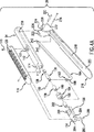
図1と2は本発明の鉗子20を例示する斜視図である。鉗子20は、ハンドルアセンブリ26に作動可能に連結される基端24と、把持アセンブリ30に作動可能に連結される末端28とを有するフレキシブルシャフト22を有するシャフトアセンブリを持っている。テレスコープ式の多数チューブ32は入れ子式に縮引されてハンドルアセンブリ26内に格納され(図2参照)、そして、シャフト22を完全に覆うためにフルに伸張される(図1参照)。
1 and 2 are perspective views illustrating a
シャフトアセンブリとテレスコープ式チューブ
ここで図2A、2B、および3Aについて言及すると、1実施の形態では、シャフト22を多数のビーズ36で作ることができる。1つの非限定的な好ましい実施の形態において、シャフト22は、それがいかなる他の要素によって支持されていないときに、ある点まで完全に撓むことができるように可撓性であり(言い換えれば、しなだれることができ、柔軟で、硬くない)、そして、完全に可撓性であるにもかかわらず、軸荷重にも耐えることができる。望ましくは、ビーズ36は、良好な非摩耗特性の硬い剛性材料で作られている。ビーズ36の材料の非制限的な例はステンレスとプラスチックを含んでいる。各ビーズ36は1実施の形態では、約4mm(5/32インチ)の外径である。望ましくは、20乃至200個のビーズ36を連結してシャフト22を形成することができる。図2Bと5に示すように、シャフト22内を通る軸方向の内腔を形成するために各ビーズ36に貫通孔又は内腔38を設けることができ、この軸方向の内腔テフロン(登録商標)管39を滑り込ませせ、テフロン(登録商標)管39の中に内部ワイヤケーブル40を保持することができる。ビーズ36はテフロン(登録商標)管39上で互いに突き合わされ並列された状態でシャフト22を形成する。ケーブル40は常に緊張状態にあり、以下に詳細に説明されるように、把持アセンブリ30の顎の開閉を制御するのに利用される。ケーブル40をクランプ装置で使用されるいかなる従来のケーブルの形態とすることができ、例えば、ステンレス、タングステン等から作られる。
Shaft Assembly and Telescopic Tube Referring now to FIGS. 2A, 2B, and 3A, in one embodiment, the
シャフト22の基端24は、図5と6で示されるようにハンドルアセンブリ26内に固定される基部チューブ42の末端44に当接する。テフロン(登録商標)管39とケーブル40は基部チューブ42内を通って延伸する。止め具部材46はチューブ42の基端48に螺合されている。複数のワッシャ50はチューブ42の基端48のおねじに螺合する。チューブ42は、ワッシャ50が圧迫されるようになるまで、止め具部材46にねじ込まれる。このねじ接合がゆるむのを防ぐために十分なトルクを適用することができる。
The
ワッシャ50により、鉗子20のメーカーがハンドルアセンブリのアセンブリの間にチューブ42と止め具部材46のねじ接続長さを調整することが可能になる。チューブ42と止め具部材46のねじ接続の長さを調整することで、シャフト22の長さを調整することができ、これにより、(i)ケーブル40を緊張させ、そして(ii)把持アセンブリ30の顎260、262の最大の開角度を調整することができる。この点に関し、ワッシャ50は、ワッシャ50の数を変えることによって、チューブ42と止め具部材46のねじ接続の調整を容易にする。ねじ接続の調整に関するワッシャ50の数を変更することの効果は以下の通り例証することができる。例えば、ワッシャ50を追加することによって、ねじ接続(止め具部材46とチューブ42の間のもの)の長さは減少する。この状況で、止め具部材46とチューブ42は互いに遠ざかるように移動されシャフト22の長さを増加させる。シャフト22の長さを増加させることによって、シャフト22の各端部からはみ出るケーブル40の長さは減少する。これはシャフト22に対するケーブル40の長さを有効に減少させ、これにより、ケーブル40の最大の張力を増加させ把持アセンブリ30の顎の最大開角度を減少させる。同様に、ワッシャ50の数を減らすことによって、ねじ接続の長さは増加される。この状況で、止め具部材46とチューブ42は互いに向かって動かされ、その結果、シャフト22の長さを減少させる。これはシャフト22に対するケーブル40の長さを有効に増加させ、これにより、ケーブル40の最大の張力を減少させ把持アセンブリ30の顎の最大開角度を増加させる。
Washer 50 allows
ワッシャ50の代わりに、また、単一の止めナット(図示省略)を使用することも可能である。メーカーは、チューブ42と止め具部材46のねじ接続長さを増加または減少させ、次に、ねじ接続がゆるくなるのを防ぐために止めナットを締めることができる。
Instead of the
ビードシャフト22に剛性を与えるために複数のテレスコープ式チューブ32を使用することができる。それぞれのテレスコープ式チューブ32は内腔52を有する。いかなる数のテレスコープ式チューブ32を提供することができ、本発明の1実施の形態によれば、2乃至5のテレスコープ式チューブ32が提供される。それぞれのテレスコープ式チューブ32はどのような必要断面(例えば、円、正方形、長方形、または、楕円等)も持つことができ、望ましくは、特にプラスチック、アルミニウム、チタニウム、およびステンレスなどの実質的に剛性の材料から作られている。最近位のテレスコープ式チューブ32aは最大直径と、最も大きい内腔52を有し、テレスコープ式中間チューブ32の内腔の直径とサイズは、最も小さい直径と最も小さい内腔52を持つ最遠位テレスコープ式チューブ32bに至るまで次第に小さくなる。この構成により、テレスコープ式の複数のチューブ32を互いに中に入ることができるように入れ子にすることができ、かつ、ハンドルアセンブリ26のチューブハウジング54の中に格納することができる。それぞれのテレスコープ式チューブ32はまた、その末端の外面上に設けられた1つのブッシング56を有する。これらのブッシング56はテレスコープ式の複数のチューブ32が縮引されてチューブハウジング54内に保持されたときに、止め具部材(図6参照)として機能する。基部チューブブッシング68は最遠位入れ子チューブ32aに取り付けられ、その外径は、チューブハウジング54(図4A、5、および6を参照)の内腔110の内側に滑り込むように適合されている。チューブハウジング54は、以下に、より詳細に説明される。
ブッシング56は、止め具部材として機能することに加えて、また、テレスコープ式チューブ32が互いに中に摺動することを容易にし、かつ、シャフト22がテレスコープ式チューブ32で完全に覆われるときにシャフト22の領域に剛さを与えるように機能する。テレスコープ式チューブ32が互いの中に滑らかに滑り込むことを促進させることに関して、ブッシング56をテレスコープ式チューブ32よりもさらに硬いステンレスから作ることとしてもよく、あるいはプラスチックから作ることもできる。テレスコープ式チューブ32の滑らかな滑りは、ブッシング56とテレスコープ式チューブ32の滑らかな表面仕上げによって達成されるであろう。また、ブッシング56がプラスチックで作られるならば、滑らかな滑りはテレスコープ式チューブ32とブッシング56の間の低摩擦係数によって達成されるだろう。剛さを促進することに関し、隣接するテレスコープ式チューブ32の端部のオーバラップは、把持アセンブリ30の顎に作用するいかなる横荷重又はモーメントにも対抗するように機能する。
In addition to functioning as a stop member, the
テレスコープ式チューブ32の断面が円形であるならば、平らな面(例えば、図11の57を参照)を機械加工その他の方法により各テレスコープ式チューブ32の外面に設けることができ、そして、別の平らな面59をそれぞれのブッシング56の内腔の内面に機械加工により設けることができる。これにより、鉗子20の使用の際にシャフト22にトルクが与えられたときにテレスコープ式チューブ32が互いに回転することを防ぐことができる。
If the cross section of the
さらに、ブッシング56をそれぞれのテレスコープ式チューブ32の外面に設ける必要はない。図12で示されるように、ブッシングの56aをそれぞれのテレスコープ式チューブ32の内腔61に設けて隣接するテレスコープ式チューブ32の外面に対して摺動させるようにすることができる。
Further, the
図2A、7A、8、および9で示されるように、ロッキングハブ58はシャフト22の末端28に設けられている。図3Bは、ロッキングハブ58の他の要素から分離した状態を示す。ロッキングハブは、2つの環状の端部62と64の間に凹形の環状チャンネル60を有する。ロッキングハブ58はまた、ケーブル40が内部を延伸する内腔66を備えるシャフト65を有する。
As shown in FIGS. 2A, 7A, 8, and 9, a locking
図1、6、および9で示されるように、ロッキングメカニズム70は最遠位テレスコープ式チューブ32bの最遠位端に取り付けられている。ロッキングメカニズム70は以下で説明する方法でロッキングハブ58に係合するように設けられており、シャフト22全体がテレスコープ式チューブ32によって覆われ支持されることを確実にし、かつ、ロッキングメカニズム70がロッキングハブ58に係合するときに把持アセンブリ30の顎の回転を防ぐ。ロッキングメカニズム70は内側ロックハウジング72と、外側ロックハウジング74を含んでいる。図3Cと3Eは内側ロックハウジング72の他の要素から分離された状態を示す。内側ロックハウジング72は、貫通内腔を有するほぼ円筒体76である。この内腔は、末端部80に直接連通する基部78を有する。基部78は末端部80より大きい直径を持ち、そして、図6に示すように、最遠位テレスコープ式チューブ32bの最遠位端を取付け保持するに設けられている。2個の環状リッジ82と84は、内腔の末端部80の位置において円筒体76から延伸し、それらの間に環状スペース86を定める。環状スペース86において円筒体76回りに離間した複数の半径方向の孔90が配設されている。例えば、4つの孔が設けて、これらを互いに90度離間することができる。ボール88は各孔90に座り、末端部80の内腔側にわずかにはみ出ている。ボール88が末端部80の内腔に落ち込むこと防ぐために各穴90に斜めの段89が設けられている。コイルばね91を環状スペース86において円筒体76の回りに巻きつけて、ボール88を斜め段89に接触するように保っている。末端部80の内腔にはみ出したボール88の部分は、以下のように、ロッキングハブ58の凹形チャンネル60に対する着脱を容易にする。ロッキングハブ58が末端部80の内腔に挿入されるときロッキングハブ58の環状端部62はボール88を放射状外側に押す。ボール88が軸方向に凹形チャンネル60に並べられると、コイルばね91はボール88のはみ出ている部分を凹形チャンネル60内に押す。半径外側方向力(環状端部62からのもの)と、半径内側方向力(コイルばね91からのもの)のこの組み合わせは、内側ロックハウジング72をロッキングハブ58にロックする。狭くされた環状端部92は円筒体76の基端に隣接して設けられる。
As shown in FIGS. 1, 6, and 9, the
図3Dは外側ロックハウジング74を示す。外側ロックハウジングは、内腔を持ったほぼ円筒状の円筒体100を有する。この内腔は3つの異なるセクション(部分)、即ち、最小径であり内側ロックハウジング72の端部92を受けるように設けた第1セクション102と、第1セクション102の直径よりも大きい直径を持ち、ほぼ基部セクション76の位置において内側ロックのハウジング72の領域を受けるように設けられた第2セクション104と、第2セクション104の直径よりも大きい直径を持ち、広径リッジ82,84を受けるように設けた第3セクションを有する。
FIG. 3D shows the
使用の際には、外側ロックハウジング74は(例えば、溶接、接着剤、または、圧力嵌めによって)内側ロックハウジング72に嵌合固定されている。外側ロックハウジング74はボール88とコイルばね91を保護すると共に、コイルばね91を環状スペース86内に保持し、ボール88を孔90の中に保持する。
In use, the
本発明は接続ビーズ36を数珠繋ぎしたものとしてフレキシブルシャフト22を例示するが、シャフト22を可撓性材料とすることも可能である。この例は、超弾性金属管、閉鎖形コイルばね、グーズネック、薄肉管等である。ビーズ36を異なる形に設けることもまた可能であり、例えば、筒状のビーズ、楕円形のビーズ、正方形のビーズ、玉継ぎ手のビーズである。いかなる使用材料の場合でも、ビーズ36またはフレキシブルシャフト22を形成する材料は可撓性を有したまま、圧縮荷重(ケーブル40の張力に対する反力)に耐えることができなければならない。
The present invention exemplifies the
ハンドルアセンブリ
ハンドルアセンブリ26を図4−6に最も良く示す。ハンドルアセンブリ26はチューブハウジング54を有し、このハウジングは、内部を貫通して延伸する内腔110を持ったほぼ円筒形の管である。チューブハウジング54はその一側において、基部環状フランジ114とチューブハウジング54のほぼ中央の間に位置する平面の凹んだ領域112を有する。凹んだ領域112は静止したハンドルピース116を受けるように設けられており、例えば、ねじ118をハンドルピース末端の開口120を通して凹んだ領域112の末端のねじ孔122に螺合することによって、ハンドルピース116の末端を凹んだ領域112に連結することができる。ハンドル断片116はまた、フランジ114を受けるように設けたその内面に溝124を有する(図5参照)。
Handle
ハンドルアセンブリ26は、ケーブルホルダ128とアジャスタピース130を含んでなるケーブルターミネータアセンブリを収容する。図4Bはケーブルホルダ128を示し、ホルダ128は基部シャフト132と、該シャフト132に取り付けられたほぼ筒状のケーブルヘッド134を有する。ケーブルヘッド134の前面136は、ケーブルヘッド134の外側からセンターまで切り込まれた鍵穴状のスロットを有する。このスロットはケーブルヘッド134の中に丸くされた部分138を有し、かつ、この丸くされた構成部分よりもサイズが小さな軸方向部分140を前面136に有する。ケーブル40の球状の端部142(図5参照)は丸くされた部分138の中に保持され、ケーブル40は軸方向部分140を通って延伸する。球状の端部142のサイズは軸方向部分140よりも大きいので、球状の端部142は丸くされた部分138の中にしっかりと保持される。ケーブル40の緊張と把持アセンブリ30の顎の最大開角度を調整または較正するためにアジャスタピース130が回転されたときに、ケーブルホルダ128が回転することを防ぐために、ケーブルヘッド134がチューブハウジング54の中のキー溝145(図5と6参照)に軸方向に渡って乗るようにダウエルピン144が設けられている。
The
図4Cはアジャスタピース130を示す。アジャスタピースは、その中を延伸するねじが切られた内腔150を有するほぼ筒状の体148を有する。2つの対向壁152と154は筒状体148の基端から延伸し、その間に内部スペースを定める。各壁152,154は、それぞれ互いに向かい合った開口156,158を有し、これらの開口にピン160が通される(図4A参照)。壁152、154の間の内部スペースは伝達リンク164のフック端162を受けるように設けられており、ピン160が開口156、158と、フック端162の整列された開口166に挿入されてフック端162とアジャスタピース130のピボット軸連結を構成している。ケーブルホルダ128のシャフト132はアジャスタピース130の遠位面170の開口168を通して内腔150に挿入される。内腔150のめねじに螺合するおねじ172をシャフト132に設けることができる。
FIG. 4C shows the
シャフト22の長さを調整することによりケーブル40の最大張力と把持アセンブリ30の顎の最大開度を調整または較正することに加えて、直接ケーブル40の長さを変えるのによってまた、ケーブル40の最大張力と把持アセンブリ30の顎の最大開角度を調整または較正することができる。ピン160がアジャスタピース130をフック端162に連結しないときはアジャスタピース130を回すことによって、ケーブル40の最大緊張と把持アセンブリ30の顎の最大開角度を調整または較正されることができる。例えば、ピン160が開口156、158、および166から取り外されるとき、伝達リンク164のフック端162をアジャスタピース130から切り離すことができる。これはメーカーによってのみなされる。アジャスタピース130を回転させることによって、ケーブルホルダ128のねじ172はねじ孔(内腔)150内で移動し、回転の方向に従ってケーブル40の長さを増加または減少させる。ケーブル40の長さを減少させることによって、把持アセンブリ30の顎はわずかに閉じてケーブル40が顎に伝えることができる最大力が増加される。ケーブル40の長さを増加させるのによって、顎はわずかに開いてケーブル40が顎に伝えることができる最大力は減少する。アジャスタピース130が回転されているとき、ダウエルピン144がチューブハウジング154のキー溝145で保持されるので、ケーブルホルダ128は回転することができない。
In addition to adjusting or calibrating the maximum tension of the
ハンドルアセンブリ26は、アジャスタピース130が内部を往復摺動することができる内腔180を有する筒状のプラスチック性のブッシング178をさらに収容する。また、図5を参照して、ブッシングハウジング184は、チューブハウジング54の内腔110に設けためねじにその基端に隣接した位置(すなわち、フランジ114の領域)で螺合するおねじ188(図4A参照)を有する。ブッシングハウジング184の基端は、ブッシング178を内腔186内に保持する基部止め具として機能する肩190を有する。
The
図4Aと5で示されるように、ばねハウジング196はハンドルピース116の基端198に取り付けられる。図4Dはばねハウジング196を示す。ばねハウジングは、中実部194と、溝部200を有する。内腔201は中実部194に設けられ、圧縮コイルばね202は内腔201で保持される。通常、圧縮コイルばね202は、鉗子20が使用中でないときに、ハンドルアセンブリ26のハンドルピース116、216を開くように保つために伝達リンク164(溝部200の中を移動する)のフック端162に対して付勢される。溝部200の底部に沿って軸方向スリット208を設けて伝達リンク164がその中を往復できるように構成している。ばねハウジング196の中実部194は2つの孔204を有し、これらの孔の中をねじ206が延伸してばねハウジング196をハンドルピース116の基端198において2つのねじ付き開口(図示省略)に螺合する。ハンドルアセンブリ26はまた、内面220に設けられた軸方向チャンネル218を有する細長い旋回ハンドルピース216を含んでいる。2個の対向壁222,224はハンドルピース216の末端から延伸して、その間に内部スペースを定める。各壁222,224はそれぞれ、対向する第1開口226,228を有し、ピン230をこれらの開口に通して延伸させることができる。各壁222と224はまた、対向する第2開口232を有し、これらの開口に第2ピン236を通して延伸させることができる。壁222、224の間の内部スペースはチューブハウジング54の円筒管を受けるように設けられ、第1ピン230を第1開口226、228と、チューブハウジング54の対向開口238に挿入しチューブハウジング54とハンドルピース216のピボット連結を構成している。壁222,224の間の内部スペースはまた、伝達リンク164の末端240を受けるように設けられ、第2開口232と末端240の対向開口242に第2ピン236を挿入して伝達リンク164とハンドルピース216とのピボット連結を構成している。軸方向チャンネル218は、ハンドルピース116と216が一緒に把持される(すなわち、閉じられる)ときに伝達リンク164を受けるように設けられている。図5と6で示されるように、基部チューブ42、止め具部材46、およびワッシャ50は、上で説明した方法によりチューブハウジング54の内腔110内に本固定(仮固定ではない)され、止め具部材46は内腔110の中に形成された肩250に当接する。ケーブル40はビーズ36の内腔38、基部チューブ42の内腔252、止め具部材46、およびケーブルハウジング128の軸方向部分140を通って延伸し、ケーブルハウジング128の丸くされた部分138の中で保持される球状の端部142で終端する。
As shown in FIGS. 4A and 5, the
ハンドルアセンブリ26は通常、図5と6で示される開位置に偏倚される。ユーザが2つのハンドルピース116と216を把持すれば、ピン230と236における回転は伝達リンク164を基部方向(矢印A1参照)に押し、フック端162がばね202の通常の付勢力に打ち勝ち、アジャスタピース130とケーブルハウジング128を同じ基部方向に引く。ケーブルハウジング128は、それが基部方向に移動するのに従って、ケーブル40の球状端部142を引くので、ケーブル40を基部方向に引くことになる。
The
これに関して、止め具部材46、基部チューブ42、およびビーズ36は一緒にケーブル40に反力を与えて緊張させる。この張力を次の通り例示することができる:ロッキングハブ58は最遠位ビーズ36に当接し、他のビーズ36は基部チューブ42に当接し、基部チューブ42は次に止め具部材46に当接し、止め具部材46が順番にチューブハウジング54の肩250に当接する。チューブハウジング54の位置が固定され、かつ、ロッキングハブ58が把持アセンブリ30と30aの静止した顎ハウジング(以下に説明するように、270と352)に固着されているので、ビーズ36と、基部チューブ42と、止め具部材46は圧縮状態である。ケーブル40が次に緊張され自由に動くことができるので、把持アセンブリ30の顎260と262は接近して閉じることができる。
In this regard, the
ユーザがハンドルピース116、216の把持を緩めると、ハンドルアセンブリ26のばね202は伝達リンク164を遠位方向(すなわち、矢印A1と反対の方向)に押すことによってハンドルピース116、216を開くように付勢する。同時に、把持アセンブリ30のねじりばね284(以下に詳細に説明される、あるいは、以下で説明される図10B又は10Cのばね420又は420A)は顎260と262を開くように付勢し、遠ケーブル40を遠位方向(すなわち、矢印A1と反対方向)に引く。
When the user loosens the grip on the
ケーブルハウジング128とアジャスタピース130の構造を本発明の別の実施の形態に従って変更することができる。この実施の形態では、ケーブルホルダ128とキー溝145が省略され、ケーブル40の端部142を開口168に通してアジャスタピース130の内腔150内に延伸させて、(例えば、クリンピングすることにより)内腔150の中に固定する。
The structure of the
把持アセンブリ30
把持アセンブリ30の1つの実施の形態を図7−9に関して例示する。図10A−10Cは別の実施の形態の把持アセンブリ(番号30aで示す)を例示する。把持アセンブリ30は外科手術の間に血管を咬合するために血管をつかむことに使用されている。図7Aの把持アセンブリ30は、回転して互いに開き、閉じることができる1対の把持顎260と262を有する。各顎260と262にはインサート264が設けられ、これらのインサート264は商業的に利用可能な公知のいかなる形態のインサートとすることができる。顎260と262にインサート264を固定するテクニックとメカニズムはまた周知であり、ここでは説明しない。
One embodiment of the gripping
図7Aと7Bに言及し、第1顎260の基端266は静止した顎ベース270の内腔268内に固定される。顎ベース270は凹形の上面274を持つ底部272を有し、かつ、遠位部分において内腔268を含む。垂直壁276は底部272から延伸し、内面に数字「6」のような形状のくぼみ278を有し、「6」の底部のほぼ中心に置かれる円筒(中空)シャフト282を有する。中空シャフト282はめねじを有する。シャフト282の回りのくぼみ278内にねじりばね284をその1脚がくぼみ278の「6」の直線部に保持されるように保持する。曲がったくぼみ286は垂直壁276にダウエルピン325を受けるように設けられる。垂直壁276は、凸状反りを有する遠位面292を有する。底部272の基端290に開口288を設けており、この開口は凹形上面274の位置に連通する。ロッキングハブ58のシャフト65は開口288に嵌合され、(例えば、溶接又は接着により)そこに保持される。
Referring to FIGS. 7A and 7B, the
図7Aと7Cを参照し、第2顎262の基端300はピボット式顎ベース304の内腔302に保持される。顎ベース304は、内腔302を囲む接続ヘッド306と、垂直壁ピース308を有する。垂直壁ピース308は、数字「6」の形状のくぼみ310であって、「6」の底部のほぼ中心に位置する丸孔314を有するくぼみを内面312に有する。くぼみ310は顎ベース270のくぼみ278に対向するように形成されるので、ねじりばね284の一部をまたくぼみ310内に保持することができる。しかしながら、くぼみ310の数字「6」の形状が顎ベース270のくぼみ278の数字「6」の形状と逆にされるので、ねじりばね284の反対側の脚はくぼみ310の「6」の直線部(例えば、321)内で保持される。ねじりばね284のそれぞれの対向脚が2つの異なったくぼみ278と310の別々の直線部で保持されるので、ねじりばね284は2個の顎のベース270と304の間でしっかりと保持される。
With reference to FIGS. 7A and 7C, the
さらに、第1湾曲スロット316は垂直壁ピース308の下側周囲に沿って設けられ内面312から中側に延伸する。第1スロット316は、接続ヘッド306に隣接した球状の、または、拡大領域324から延伸し、次に、垂直壁ピース308の下側周囲に沿って伸びて第2湾曲スロット318と連通する。第2湾曲スロット318はまた、垂直壁ピース308の下側周囲に沿って延伸するが、内面312から中側に延伸するのではなく、垂直壁ピース308の底面320から中側に延伸する。図8で示されるように、ケーブル40の球状末端326は第1スロット316の球状領域324で保持される。ケーブル40は次に内側に保持され、第1スロット316と第2スロットに沿って延伸し、底面320において第2スロット318を出て、顎ベース270の開口288を通ってロッキングハブ58内に延伸し、つぎに、ビーズ36の内腔38を通る。接続ヘッド306の基部壁322は、顎ベース270の遠位面292の凸状反りの補足となるように構成された凹形の反りを有する。さらに、孔323はダウエルピン325を受けるために顎ベース304の内面312に設けられる。
Further, the first
孔323とダウエルピン325は湾曲くぼみ286に並べられる。顎ベース270と304の内面280と312の間にシム328を配設する。シム328は、顎ベース270と304のくぼみ278と310に対向する中央開口330を有する。シム328はまた、孔323と湾曲くぼみ286に対向する孔332を有し、この孔をダウエルピン325が通って延伸する。シム328は顎ベース270に対する顎ベース304の滑らかな回転を容易にする。この滑らかな回転は、良好な表面仕上げと、シム328と回転顎ベース304の表面312の間の低摩擦係数によって達成される。
The
把持アセンブリ30は、シム328を顎ベース270と304の間に配設し、ショルダねじ334を丸孔314と、シム328の開口330に通してシャフト282の中空内部のめねじに螺合させることによって組み立てられる。その結果、顎ベース304は、ねじ334によって定められるピボット点回りに顎ベース270に関して旋回する。より明確に言えば、顎ベース270は静止しており、顎ベース304の基部壁322の表面が顎ベース270の表面292に関して上下に摺動した状態で顎ベース304は顎ベース270に関して旋回する。さらに、ダウエルピン325は湾曲くぼみ286まで延伸し、湾曲くぼみ286内で往復する。湾曲くぼみ286の対向両端はストッパ面を定め、回転顎ベース304の両方の方向の回転範囲を制限する。
The gripping
ねじりばね284は、顎260と262を開くように付勢するトルクを与える。したがって、ハンドルアセンブリ26が開かれると、ケーブル40の張力が解放され、ねじりばね284は静止した顎ベース270に関して回転顎ベース304を開くように付勢する。
鉗子20の作動を図1、2、5、6、8、および9を参照して理解することができる。使用中でないときに、ハンドルピース116と216は開位置では通常離間され、顎260と262もまた通常離間される。このとき、シャフト22を覆うためにテレスコープ式チューブ32を伸張することができ(図1、5、および9参照)、あるいは、テレスコープ式チューブ32を縮引してチューブハウジング54の中に格納することができる(図2、6、および8参照)。テレスコープ式チューブ32がチューブハウジング54の中に入れ子にされ格納されるとき(図2、6、および8参照)、内側ロックハウジング72と外側ロックハウジング74はチューブハウジング54に隣接してシャフト22の基端24に位置される。テレスコープ式チューブ32がシャフト22を覆うために伸張されるとき(図1、5、および9参照)、上で説明したように、内側ロックハウジング72と外側ロックハウジング74は顎ベース270に隣接してシャフト22の末端28においてロッキングハブ58に固定される。
The operation of the
鉗子20が血管をつかむのに使用されるとき、外科医は、知られている外科手術手技を使用することで顎260、262をトロカール内に導き、あるいは、外科手術部位に導き、ハンドルピース116と216を掴んでそれらを接近させる。ハンドルピース116と216が接近されると、ケーブル40は、上で説明したように、基部方向に引かれる(図6の矢印A1参照)。ケーブル40が基部方向に引かれると、ケーブル40の張力は図8の矢印A2の向きに回転顎ベース304にトルクを発生させる。このトルクは、ねじりばね284からのトルク(これは顎262を開くように付勢する)が打ち負かされて顎262が矢印A2の向きに回転して他方の顎260に向かって閉じて血管をつかむようになる点まで増加する。
When the
顎260、262が血管をつかんだとき、外科医はテレスコープ式チューブ32を引っ込めることができる。外科医は全てのチューブ32をチューブハウジング54の中に完全に入れ子にして格納し(図2、6、および8参照)、全体のシャフト22を露出することができる。代わりに外科医は、テレスコープ式チューブ32の全長ではなく、一部を露出させるためにテレスコープ式チューブ32のすべてではなく、いくつかを引っ込めることができる(図13参照)。その時外科医は希望する方向にシャフト22の露出された部分を曲げることが可能であり、それにより、ハンドルアセンブリ26を外科手術部位から遠ざけて外科医の外科手術部位へのアクセスを妨害することがないようにすることができる。外科医がハンドルピース116と216のグリップを解放すると、ばね202は、伝達リンク164を遠位方向(例えば、矢印A1と反対の方向)に押すのによって、ハンドルピース116と216を開くように付勢する。これはケーブル40の緊張を弱めるので、ねじりばね284が顎260と262を同時に開くように付勢することができるので、ケーブル40を遠位方向に引く。
The surgeon can retract the
把持アセンブリ30a
別の実施の形態の把持アセンブリ30aを図10A−10Cに関して例示する。図10A−10Cの把持アセンブリ30aはまた、回転して開き、閉じることができる1対の把持顎260と262を有する。各顎260と262にインサート264を設けている。これらのインサート264と顎260と262は図7Aに関連して上で説明したものと同じにすることができる。
Another embodiment of a
第1顎260の基端266は静止した顎ベース352の内腔350内に保持される。顎ベース352は、内腔350を定める遠位管状部354と、1対の対向垂直壁356,358を持ったホルダ部と、ロッキングハブ58(図10Aでは図示省略)に取り付けられた基部管状部360を有する。対向垂直壁356と358はその間にスペース368を定め、それぞれの垂直壁356と358は、対向する開口362と364を有する。基部管状部360は、ケーブル40の一部が内部を延伸する内腔366を有する。
The
第2顎262の基端300は回転顎ベース72の内腔370に保持される。顎ベース372は、内腔370を定める軸方向部(縦部)374と、第1孔378を持った横部376を有するL形の形状である。横部376は、間にスペースを定める2個の平行な壁と、これらの平行な壁に設けられた対向第2孔380を含んでなる。
The
ケーブルフィティング388は、ケーブル40の最遠位端が内側に嵌合固定される基部内腔を有する。(図10B,10C参照)。ケーブルフィティング388の遠位部は、間にスペースを定める2個の対向壁390と392を有する。
The
顎伝達リンク400は、基部404に関して傾いた遠位部402を備える傾斜構造とされている。遠位部402は開口406を有し、基部404はそれ自身の開口408を有する。遠位部402は横部376の2個の平行壁の間で合わせられて、開口406は第2孔380に合わせられている。
The
ケーブルフィティング388はケーブル40の末端を担持し、顎ベース352の内腔366を通ってスペース368内に延伸する。伝達リンク400の基部404はケーブルフィティング388の2つの対抗壁390と392の間のスペースで受け取られ、基部404の開口408が壁390と392のそれぞれの孔410に合わせられる。ダウエルピン412は基部404の開口408とそれぞれの壁390と392の孔410を通って延伸してケーブルフィティング388と基部404のピボット連結を構成する。さらに、伝達リンク400の遠位部402の開口406は顎ベース372の第2孔380に合わせられるので、別のダウエルピン414が開口406と第2孔380を通って延伸して顎ベース372と遠位部402のピボット連結を構成する。さらに別のダウエルピン416を顎ベース352の両壁356と358の合わせた孔362と364及び顎ベース372の第1孔378に通して延伸させて顎ベース352と372のピボット連結を構成することができる。
Cable fitting 388 carries the distal end of
ばね420を顎ベース352の中で設けて、静止顎ベース352に対して回転顎ベース372を付勢する。図10Bで示される1つの実施の形態では、ばね420はスペース368の中で保持され、顎の横部376に付けられた第1端部372と、基部管部360の内腔422内に固定された第2端部を有する。図10Cで示される別の実施の形態では、ばね420aを伝達リンク400とケーブルフィティング388に巻きつけることができる。また、さらなる代替手段として、同じ機能を実行するために板ばね又はねじりばねを設けることができる。
A
把持アセンブリ30aの動作を以下に説明する。鉗子20が血管をつかむのに使用されるとき、外科医はハンドルピース116と216を握ってそれらを接近させる。ハンドルピース116と216が接近すると、ケーブル40は、上で説明したように、基部方向(図6の矢印A1参照)に引かれる。ケーブル40が基部方向に引かれるのに従って、ケーブル40の末端はケーブルフィティング388を基部方向に引く。ケーブルフィティング388は顎ベース372の横部376をダウエルピン416の軸回り、図10Bの矢印A3の向きに回転させる。これにより、回転顎ベース372を静止顎ベース352に向かって旋回させて血管をつかむ。
The operation of the
他の実施の形態でそうすることができるように、顎260、262が血管を掴んだときに、外科医はテレスコープ式チューブ32を完全に縮引してすべてのテレスコープ式チューブ32を入れ子にしてチューブハウジング54の中に格納することができ、あるいは、外科医は、シャフト22の(全長ではなく)一部だけを露出させるためにテレスコープ式チューブ32のすべてではなく、いくつかを縮引することができる。外科医は、シャフト22の露出している部分を所望の方向に曲げることが可能になるので、ハンドルアセンブリ26を外科手術部位から遠ざけて外科医の外科手術部位へのアクセスを妨害することがなくなる。
As can be done in other embodiments, when the
外科医がハンドルピース116と216の握りを解放すると、ばね202は、上に説明したように、ハンドルピース116と216を引き離すように付勢し、ばね420又は420aは顎ベース372を顎ベース352から遠ざけるように付勢する。
When the surgeon releases the grip on the
このように本発明は、外科手術部位への外科医のアクセスを妨げることのない、外科手術部位で血管を効果的に挟むことができるクランプ装置(鉗子アセンブリ20)を提供する。フレキシブルシャフトと入れ子にできるテレスコープ式チューブ32を含むシャフトアセンブリは、シャフトアセンブリを完全に剛性にすることができ、かつ完全に可撓性にすることができる。テレスコープ式チューブ32が完全に伸張されるときに形成される剛性シャフトは、顎260、262に作用する軸荷重、横荷重、モーメント、およびトルクに耐えることができる。その結果、外科医は顎260、262を使用して外科手術部位の周りを突いたり、突き刺したりすることができる。
Thus, the present invention provides a clamping device (forceps assembly 20) that can effectively pinch a blood vessel at the surgical site without interfering with the surgeon's access to the surgical site. A shaft assembly that includes a
上の説明は本発明の特定の実施の形態について述べたものであるが、れの技術思想から逸脱することなく多くの変更が可能であることが理解されるであろう。添付の特許請求の範囲は、本発明の真の範囲と技術思想の中に含まれるような変更をカバーすることを意図するものである。 Although the above description describes specific embodiments of the present invention, it will be understood that many modifications can be made without departing from the spirit of the invention. The appended claims are intended to cover such modifications as would fall within the true scope and spirit of the invention.
Claims (34)
要素をつかむために開閉可能な1対の顎を有する把持アセンブリと、
シャフトアセンブリであって、
前記ハンドルアセンブリと連結される基端と、前記把持アセンブリと連結される末端を有し、内腔を定めるフレキシブルシャフトと、
前記フレキシブルシャフトの前記内腔を通って延伸するケーブルであって、前記ハンドルアセンブリに作動可能に連結された基端と、前記把持アセンブリに作動可能に連結された末端とを有するシャフトと、
複数の剛性テレスコープ式チューブであって、該複数のテレスコープ式チューブが互いに完全に入れ子にされる第1位置と、該複数のテレスコープ式チューブが完全に伸張されて前記フレキシブルシャフトを完全に覆う第2位置とに位置される前記複数の剛性テレスコープ式チューブを有するシャフトアセンブリとを、
含んでなる鉗子。A handle assembly;
A gripping assembly having a pair of jaws openable and closable to grasp the element;
A shaft assembly,
A flexible shaft having a proximal end coupled to the handle assembly and a distal end coupled to the gripping assembly and defining a lumen;
A cable extending through the lumen of the flexible shaft, the shaft having a proximal end operably connected to the handle assembly and a distal end operably connected to the gripping assembly;
A plurality of rigid telescopic tubes, wherein the plurality of telescopic tubes are fully nested within each other, and the telescopic tubes are fully extended to fully engage the flexible shaft A shaft assembly having the plurality of rigid telescoping tubes positioned in a second covering position;
Forceps comprising.
要素をつかむために開閉可能な1対の顎を有する把持アセンブリと、
シャフトアセンブリであって、
前記ハンドルアセンブリに連結される基端と、前記把持アセンブリと連結される末端を有し内腔を定めるフレキシブルシャフトと、
前記フレキシブルシャフトの前記内腔を通って延伸するケーブルであって、前記ハンドルアセンブリに作動可能に連結された基端と、前記把持アセンブリに作動可能に連結された末端を有するケーブルと、
縮引可能なほぼ剛性の被覆であって、該被覆が前記フレキシブルシャフト全体を露出する第1位置と、前記被覆が前記フレキシブルシャフトを完全に覆う第2位置とに位置される被覆を有するシャフトアセンブリとを、
含んでなる鉗子A handle assembly;
A gripping assembly having a pair of jaws openable and closable to grasp the element;
A shaft assembly,
A proximal end coupled to the handle assembly; a flexible shaft having a distal end coupled to the gripping assembly and defining a lumen;
A cable extending through the lumen of the flexible shaft, the cable having a proximal end operably connected to the handle assembly and a distal end operably connected to the gripping assembly;
A shaft assembly having a retractable, substantially rigid coating, wherein the coating is located in a first position where the entire flexible shaft is exposed and in a second position where the coating completely covers the flexible shaft. And
Forceps comprising
要素をつかむために開閉可能な1対の顎を有する把持アセンブリと、
シャフトアセンブリであって、
前記ハンドルアセンブリに作動可能に連結される基端と、前記把持アセンブリに作動可能に連結される末端を有する可撓性の細長い部材と、
前記細長い部材と同軸である可動被覆であって、前記被覆が前記フレキシブルシャフト全体を露出する第1位置と、前記被覆が前記フレキシブルシャフトのほとんどの部分を覆う第2位置とに位置される被覆を有するシャフトアセンブリとを、
含んでなる鉗子。A handle assembly;
A gripping assembly having a pair of jaws openable and closable to grasp the element;
A shaft assembly,
A flexible elongate member having a proximal end operably coupled to the handle assembly and a distal end operably coupled to the gripping assembly;
A movable coating that is coaxial with the elongate member, wherein the coating is located in a first position where the entire flexible shaft is exposed and a second position where the coating covers most of the flexible shaft; A shaft assembly having
Forceps comprising.
Applications Claiming Priority (2)
| Application Number | Priority Date | Filing Date | Title |
|---|---|---|---|
| US09/847,135 US6544274B2 (en) | 2001-05-02 | 2001-05-02 | Clamp having bendable shaft |
| PCT/US2002/013678 WO2002087421A2 (en) | 2001-05-02 | 2002-05-01 | Clamp having bendable shaft |
Publications (2)
| Publication Number | Publication Date |
|---|---|
| JP2004527312A JP2004527312A (en) | 2004-09-09 |
| JP4270437B2 true JP4270437B2 (en) | 2009-06-03 |
Family
ID=25299852
Family Applications (2)
| Application Number | Title | Priority Date | Filing Date |
|---|---|---|---|
| JP2002584778A Pending JP2005505314A (en) | 2001-05-02 | 2002-05-01 | Clamp with foldable shaft |
| JP2002584779A Expired - Lifetime JP4270437B2 (en) | 2001-05-02 | 2002-05-01 | Forceps with a bendable shaft |
Family Applications Before (1)
| Application Number | Title | Priority Date | Filing Date |
|---|---|---|---|
| JP2002584778A Pending JP2005505314A (en) | 2001-05-02 | 2002-05-01 | Clamp with foldable shaft |
Country Status (7)
| Country | Link |
|---|---|
| US (5) | US6544274B2 (en) |
| EP (2) | EP1383433A4 (en) |
| JP (2) | JP2005505314A (en) |
| AT (1) | ATE545367T1 (en) |
| AU (1) | AU2002338531B2 (en) |
| CA (2) | CA2444473C (en) |
| WO (2) | WO2002087421A2 (en) |
Families Citing this family (392)
| Publication number | Priority date | Publication date | Assignee | Title |
|---|---|---|---|---|
| US5782396A (en) | 1995-08-28 | 1998-07-21 | United States Surgical Corporation | Surgical stapler |
| US5762256A (en) * | 1995-08-28 | 1998-06-09 | United States Surgical Corporation | Surgical stapler |
| US5865361A (en) | 1997-09-23 | 1999-02-02 | United States Surgical Corporation | Surgical stapling apparatus |
| US7435249B2 (en) | 1997-11-12 | 2008-10-14 | Covidien Ag | Electrosurgical instruments which reduces collateral damage to adjacent tissue |
| US6726686B2 (en) | 1997-11-12 | 2004-04-27 | Sherwood Services Ag | Bipolar electrosurgical instrument for sealing vessels |
| US6228083B1 (en) | 1997-11-14 | 2001-05-08 | Sherwood Services Ag | Laparoscopic bipolar electrosurgical instrument |
| US7118570B2 (en) | 2001-04-06 | 2006-10-10 | Sherwood Services Ag | Vessel sealing forceps with disposable electrodes |
| US7582087B2 (en) | 1998-10-23 | 2009-09-01 | Covidien Ag | Vessel sealing instrument |
| US7267677B2 (en) | 1998-10-23 | 2007-09-11 | Sherwood Services Ag | Vessel sealing instrument |
| US7364577B2 (en) | 2002-02-11 | 2008-04-29 | Sherwood Services Ag | Vessel sealing system |
| US20030109875A1 (en) | 1999-10-22 | 2003-06-12 | Tetzlaff Philip M. | Open vessel sealing forceps with disposable electrodes |
| ES2332143T3 (en) | 2001-04-06 | 2010-01-27 | Covidien Ag | SHUTTER AND DIVIDER OF GLASSES WITH NON-CONDUCTIVE BUMPER MEMBERS. |
| CA2443252A1 (en) | 2001-04-06 | 2002-10-17 | Sherwood Services Ag | Electrosurgical instrument which reduces collateral damage to adjacent tissue |
| US6544274B2 (en) * | 2001-05-02 | 2003-04-08 | Novare Surgical Systems, Inc. | Clamp having bendable shaft |
| US6685715B2 (en) * | 2001-05-02 | 2004-02-03 | Novare Surgical Systems | Clamp having bendable shaft |
| ES2514666T3 (en) * | 2001-10-05 | 2014-10-28 | Covidien Lp | Surgical stapling device |
| US20070185376A1 (en) * | 2002-03-11 | 2007-08-09 | Wilson Roger F | System and method for positioning a laparoscopic device |
| ES2379274T3 (en) * | 2002-03-15 | 2012-04-24 | W.L. Gore & Associates, Inc. | Coupling system useful in implant placement |
| US7695427B2 (en) | 2002-04-26 | 2010-04-13 | Torax Medical, Inc. | Methods and apparatus for treating body tissue sphincters and the like |
| US20040092973A1 (en) * | 2002-09-23 | 2004-05-13 | Nmt Medical, Inc. | Septal puncture device |
| US7270664B2 (en) | 2002-10-04 | 2007-09-18 | Sherwood Services Ag | Vessel sealing instrument with electrical cutting mechanism |
| US7931649B2 (en) | 2002-10-04 | 2011-04-26 | Tyco Healthcare Group Lp | Vessel sealing instrument with electrical cutting mechanism |
| CA2500832C (en) | 2002-10-04 | 2011-03-22 | Tyco Healthcare Group, Lp | Tool assembly for a surgical stapling device |
| EP1671593B1 (en) | 2002-10-04 | 2008-02-27 | Tyco Healthcare Group Lp | Tool assembly for surgical stapling device |
| ES2378036T3 (en) | 2002-10-04 | 2012-04-04 | Tyco Healthcare Group Lp | Surgical stapler with universal joint and previous tissue support |
| US7276068B2 (en) | 2002-10-04 | 2007-10-02 | Sherwood Services Ag | Vessel sealing instrument with electrical cutting mechanism |
| US7799026B2 (en) | 2002-11-14 | 2010-09-21 | Covidien Ag | Compressible jaw configuration with bipolar RF output electrodes for soft tissue fusion |
| CA2518829C (en) | 2003-03-13 | 2011-09-20 | Sherwood Services Ag | Bipolar concentric electrode assembly for soft tissue fusion |
| US20040243151A1 (en) | 2003-04-29 | 2004-12-02 | Demmy Todd L. | Surgical stapling device with dissecting tip |
| US9597078B2 (en) | 2003-04-29 | 2017-03-21 | Covidien Lp | Surgical stapling device with dissecting tip |
| US7160299B2 (en) | 2003-05-01 | 2007-01-09 | Sherwood Services Ag | Method of fusing biomaterials with radiofrequency energy |
| US7147638B2 (en) | 2003-05-01 | 2006-12-12 | Sherwood Services Ag | Electrosurgical instrument which reduces thermal damage to adjacent tissue |
| US7025775B2 (en) * | 2003-05-15 | 2006-04-11 | Applied Medical Resources Corporation | Surgical instrument with removable shaft apparatus and method |
| WO2004103156A2 (en) | 2003-05-15 | 2004-12-02 | Sherwood Services Ag | Tissue sealer with non-conductive variable stop members and method of sealing tissue |
| US7090637B2 (en) | 2003-05-23 | 2006-08-15 | Novare Surgical Systems, Inc. | Articulating mechanism for remote manipulation of a surgical or diagnostic tool |
| US8182417B2 (en) | 2004-11-24 | 2012-05-22 | Intuitive Surgical Operations, Inc. | Articulating mechanism components and system for easy assembly and disassembly |
| US8562640B2 (en) | 2007-04-16 | 2013-10-22 | Intuitive Surgical Operations, Inc. | Tool with multi-state ratcheted end effector |
| US8100824B2 (en) | 2003-05-23 | 2012-01-24 | Intuitive Surgical Operations, Inc. | Tool with articulation lock |
| US7410483B2 (en) | 2003-05-23 | 2008-08-12 | Novare Surgical Systems, Inc. | Hand-actuated device for remote manipulation of a grasping tool |
| US8398632B1 (en) | 2003-06-10 | 2013-03-19 | Medtronic Cryocath Lp | Surgical clamp having treatment elements |
| US7819860B2 (en) * | 2003-06-10 | 2010-10-26 | Medtronic Cryocath Lp | Surgical clamp having trasmurality assessment capabilities |
| US7044946B2 (en) * | 2003-06-10 | 2006-05-16 | Cryocath Technologies Inc. | Surgical clamp having treatment elements |
| USD956973S1 (en) | 2003-06-13 | 2022-07-05 | Covidien Ag | Movable handle for endoscopic vessel sealer and divider |
| US7857812B2 (en) | 2003-06-13 | 2010-12-28 | Covidien Ag | Vessel sealer and divider having elongated knife stroke and safety for cutting mechanism |
| US7150749B2 (en) | 2003-06-13 | 2006-12-19 | Sherwood Services Ag | Vessel sealer and divider having elongated knife stroke and safety cutting mechanism |
| US7156846B2 (en) | 2003-06-13 | 2007-01-02 | Sherwood Services Ag | Vessel sealer and divider for use with small trocars and cannulas |
| EP2428168B1 (en) | 2003-06-17 | 2014-09-17 | Covidien LP | Surgical stapling device |
| US7494039B2 (en) | 2003-06-17 | 2009-02-24 | Tyco Healthcare Group Lp | Surgical stapling device |
| JP2007504885A (en) | 2003-09-11 | 2007-03-08 | エヌエムティー メディカル, インコーポレイティッド | Devices, systems and methods for suturing tissue |
| CA2542532C (en) | 2003-10-17 | 2012-08-14 | Tyco Healthcare Group, Lp | Surgical stapling device with independent tip rotation |
| US7666203B2 (en) * | 2003-11-06 | 2010-02-23 | Nmt Medical, Inc. | Transseptal puncture apparatus |
| US8292910B2 (en) | 2003-11-06 | 2012-10-23 | Pressure Products Medical Supplies, Inc. | Transseptal puncture apparatus |
| US9848938B2 (en) | 2003-11-13 | 2017-12-26 | Covidien Ag | Compressible jaw configuration with bipolar RF output electrodes for soft tissue fusion |
| US7367976B2 (en) | 2003-11-17 | 2008-05-06 | Sherwood Services Ag | Bipolar forceps having monopolar extension |
| US7131970B2 (en) | 2003-11-19 | 2006-11-07 | Sherwood Services Ag | Open vessel sealing instrument with cutting mechanism |
| US7811283B2 (en) | 2003-11-19 | 2010-10-12 | Covidien Ag | Open vessel sealing instrument with hourglass cutting mechanism and over-ratchet safety |
| US7500975B2 (en) | 2003-11-19 | 2009-03-10 | Covidien Ag | Spring loaded reciprocating tissue cutting mechanism in a forceps-style electrosurgical instrument |
| US7442193B2 (en) | 2003-11-20 | 2008-10-28 | Covidien Ag | Electrically conductive/insulative over-shoe for tissue fusion |
| US7780662B2 (en) | 2004-03-02 | 2010-08-24 | Covidien Ag | Vessel sealing system using capacitive RF dielectric heating |
| US8216125B2 (en) | 2004-04-02 | 2012-07-10 | Civco Medical Instruments Co., Inc. | System and method for positioning a laparoscopic device |
| US7828808B2 (en) | 2004-06-07 | 2010-11-09 | Novare Surgical Systems, Inc. | Link systems and articulation mechanisms for remote manipulation of surgical or diagnostic tools |
| US7678117B2 (en) | 2004-06-07 | 2010-03-16 | Novare Surgical Systems, Inc. | Articulating mechanism with flex-hinged links |
| US9427245B1 (en) * | 2004-08-02 | 2016-08-30 | Robert F. Biolchini, Jr. | Ambidextrous locking clamp system |
| US7195631B2 (en) | 2004-09-09 | 2007-03-27 | Sherwood Services Ag | Forceps with spring loaded end effector assembly |
| US7540872B2 (en) | 2004-09-21 | 2009-06-02 | Covidien Ag | Articulating bipolar electrosurgical instrument |
| US7955332B2 (en) | 2004-10-08 | 2011-06-07 | Covidien Ag | Mechanism for dividing tissue in a hemostat-style instrument |
| WO2006055166A2 (en) * | 2004-10-20 | 2006-05-26 | Atricure, Inc. | Surgical clamp |
| US8876820B2 (en) * | 2004-10-20 | 2014-11-04 | Atricure, Inc. | Surgical clamp |
| US9700334B2 (en) * | 2004-11-23 | 2017-07-11 | Intuitive Surgical Operations, Inc. | Articulating mechanisms and link systems with torque transmission in remote manipulation of instruments and tools |
| US7785252B2 (en) | 2004-11-23 | 2010-08-31 | Novare Surgical Systems, Inc. | Articulating sheath for flexible instruments |
| US7686804B2 (en) | 2005-01-14 | 2010-03-30 | Covidien Ag | Vessel sealer and divider with rotating sealer and cutter |
| US7909823B2 (en) | 2005-01-14 | 2011-03-22 | Covidien Ag | Open vessel sealing instrument |
| US9138226B2 (en) | 2005-03-30 | 2015-09-22 | Covidien Lp | Cartridge assembly for a surgical stapling device |
| US7491202B2 (en) | 2005-03-31 | 2009-02-17 | Covidien Ag | Electrosurgical forceps with slow closure sealing plates and method of sealing tissue |
| US7780055B2 (en) * | 2005-04-06 | 2010-08-24 | Tyco Healthcare Group Lp | Loading unit having drive assembly locking mechanism |
| EP2308406B1 (en) | 2005-09-30 | 2012-12-12 | Covidien AG | Insulating boot for electrosurgical forceps |
| US7722607B2 (en) | 2005-09-30 | 2010-05-25 | Covidien Ag | In-line vessel sealer and divider |
| US7879035B2 (en) | 2005-09-30 | 2011-02-01 | Covidien Ag | Insulating boot for electrosurgical forceps |
| US7922953B2 (en) | 2005-09-30 | 2011-04-12 | Covidien Ag | Method for manufacturing an end effector assembly |
| US7789878B2 (en) | 2005-09-30 | 2010-09-07 | Covidien Ag | In-line vessel sealer and divider |
| CA2561034C (en) | 2005-09-30 | 2014-12-09 | Sherwood Services Ag | Flexible endoscopic catheter with an end effector for coagulating and transfecting tissue |
| CA2563147C (en) | 2005-10-14 | 2014-09-23 | Tyco Healthcare Group Lp | Surgical stapling device |
| FR2895071B1 (en) * | 2005-12-19 | 2008-01-18 | Giat Ind Sa | ANTI-REBOUND LOCKING DEVICE OF A DEPLOYABLE FIN OF A PROJECTILE. |
| US8241282B2 (en) | 2006-01-24 | 2012-08-14 | Tyco Healthcare Group Lp | Vessel sealing cutting assemblies |
| US8882766B2 (en) | 2006-01-24 | 2014-11-11 | Covidien Ag | Method and system for controlling delivery of energy to divide tissue |
| US8298232B2 (en) | 2006-01-24 | 2012-10-30 | Tyco Healthcare Group Lp | Endoscopic vessel sealer and divider for large tissue structures |
| US8734443B2 (en) | 2006-01-24 | 2014-05-27 | Covidien Lp | Vessel sealer and divider for large tissue structures |
| US9561045B2 (en) | 2006-06-13 | 2017-02-07 | Intuitive Surgical Operations, Inc. | Tool with rotation lock |
| US7862554B2 (en) | 2007-04-16 | 2011-01-04 | Intuitive Surgical Operations, Inc. | Articulating tool with improved tension member system |
| US8409244B2 (en) | 2007-04-16 | 2013-04-02 | Intuitive Surgical Operations, Inc. | Tool with end effector force limiter |
| US7776037B2 (en) | 2006-07-07 | 2010-08-17 | Covidien Ag | System and method for controlling electrode gap during tissue sealing |
| US8597297B2 (en) | 2006-08-29 | 2013-12-03 | Covidien Ag | Vessel sealing instrument with multiple electrode configurations |
| US8070746B2 (en) | 2006-10-03 | 2011-12-06 | Tyco Healthcare Group Lp | Radiofrequency fusion of cardiac tissue |
| WO2008045386A2 (en) | 2006-10-05 | 2008-04-17 | Tyco Healthcare Group Lp | Flexible endoscopic stitching devices |
| US8795325B2 (en) * | 2006-10-05 | 2014-08-05 | Covidien Lp | Handle assembly for articulated endoscopic instruments |
| EP2083702B1 (en) | 2006-10-05 | 2019-02-13 | Covidien LP | Axial stitching device |
| US8708210B2 (en) | 2006-10-05 | 2014-04-29 | Covidien Lp | Method and force-limiting handle mechanism for a surgical instrument |
| US9968397B2 (en) * | 2006-10-06 | 2018-05-15 | Covidien Lp | Endoscopic vessel sealer and divider having a flexible articulating shaft |
| US7866525B2 (en) * | 2006-10-06 | 2011-01-11 | Tyco Healthcare Group Lp | Surgical instrument having a plastic surface |
| US8475453B2 (en) | 2006-10-06 | 2013-07-02 | Covidien Lp | Endoscopic vessel sealer and divider having a flexible articulating shaft |
| US7845535B2 (en) | 2006-10-06 | 2010-12-07 | Tyco Healthcare Group Lp | Surgical instrument having a plastic surface |
| US8591523B2 (en) * | 2007-02-13 | 2013-11-26 | Arthrex, Inc. | Mid-point lock suture cutter |
| USD649249S1 (en) | 2007-02-15 | 2011-11-22 | Tyco Healthcare Group Lp | End effectors of an elongated dissecting and dividing instrument |
| US8267935B2 (en) | 2007-04-04 | 2012-09-18 | Tyco Healthcare Group Lp | Electrosurgical instrument reducing current densities at an insulator conductor junction |
| US7624902B2 (en) | 2007-08-31 | 2009-12-01 | Tyco Healthcare Group Lp | Surgical stapling apparatus |
| US8061576B2 (en) | 2007-08-31 | 2011-11-22 | Tyco Healthcare Group Lp | Surgical instrument |
| US8251996B2 (en) | 2007-09-28 | 2012-08-28 | Tyco Healthcare Group Lp | Insulating sheath for electrosurgical forceps |
| US8235992B2 (en) | 2007-09-28 | 2012-08-07 | Tyco Healthcare Group Lp | Insulating boot with mechanical reinforcement for electrosurgical forceps |
| US8267936B2 (en) | 2007-09-28 | 2012-09-18 | Tyco Healthcare Group Lp | Insulating mechanically-interfaced adhesive for electrosurgical forceps |
| US8221416B2 (en) | 2007-09-28 | 2012-07-17 | Tyco Healthcare Group Lp | Insulating boot for electrosurgical forceps with thermoplastic clevis |
| US9023043B2 (en) | 2007-09-28 | 2015-05-05 | Covidien Lp | Insulating mechanically-interfaced boot and jaws for electrosurgical forceps |
| US8241283B2 (en) | 2007-09-28 | 2012-08-14 | Tyco Healthcare Group Lp | Dual durometer insulating boot for electrosurgical forceps |
| US8236025B2 (en) | 2007-09-28 | 2012-08-07 | Tyco Healthcare Group Lp | Silicone insulated electrosurgical forceps |
| US8235993B2 (en) | 2007-09-28 | 2012-08-07 | Tyco Healthcare Group Lp | Insulating boot for electrosurgical forceps with exohinged structure |
| US8181315B2 (en) * | 2007-10-16 | 2012-05-22 | Peck & Hale, L.L.C. | Flexible handle interbox connector |
| KR100911248B1 (en) | 2007-10-17 | 2009-08-07 | 국립암센터 | Small laparoscopic surgical instruments |
| US7954685B2 (en) | 2007-11-06 | 2011-06-07 | Tyco Healthcare Group Lp | Articulation and firing force mechanisms |
| US8764748B2 (en) | 2008-02-06 | 2014-07-01 | Covidien Lp | End effector assembly for electrosurgical device and method for making the same |
| US8623276B2 (en) | 2008-02-15 | 2014-01-07 | Covidien Lp | Method and system for sterilizing an electrosurgical instrument |
| US8864776B2 (en) | 2008-04-11 | 2014-10-21 | Covidien Lp | Deployment system for surgical suture |
| US7942303B2 (en) | 2008-06-06 | 2011-05-17 | Tyco Healthcare Group Lp | Knife lockout mechanisms for surgical instrument |
| US8701959B2 (en) | 2008-06-06 | 2014-04-22 | Covidien Lp | Mechanically pivoting cartridge channel for surgical instrument |
| US7789283B2 (en) | 2008-06-06 | 2010-09-07 | Tyco Healthcare Group Lp | Knife/firing rod connection for surgical instrument |
| US8628545B2 (en) | 2008-06-13 | 2014-01-14 | Covidien Lp | Endoscopic stitching devices |
| US20110040308A1 (en) | 2008-06-13 | 2011-02-17 | Ramiro Cabrera | Endoscopic Stitching Devices |
| US8469956B2 (en) | 2008-07-21 | 2013-06-25 | Covidien Lp | Variable resistor jaw |
| US8257387B2 (en) | 2008-08-15 | 2012-09-04 | Tyco Healthcare Group Lp | Method of transferring pressure in an articulating surgical instrument |
| US8162973B2 (en) | 2008-08-15 | 2012-04-24 | Tyco Healthcare Group Lp | Method of transferring pressure in an articulating surgical instrument |
| US8465475B2 (en) | 2008-08-18 | 2013-06-18 | Intuitive Surgical Operations, Inc. | Instrument with multiple articulation locks |
| US9603652B2 (en) | 2008-08-21 | 2017-03-28 | Covidien Lp | Electrosurgical instrument including a sensor |
| US8795274B2 (en) | 2008-08-28 | 2014-08-05 | Covidien Lp | Tissue fusion jaw angle improvement |
| US8784417B2 (en) | 2008-08-28 | 2014-07-22 | Covidien Lp | Tissue fusion jaw angle improvement |
| US8317787B2 (en) | 2008-08-28 | 2012-11-27 | Covidien Lp | Tissue fusion jaw angle improvement |
| US8974477B2 (en) * | 2008-08-29 | 2015-03-10 | Olympus Medical Systems Corp. | Ultrasonic operating apparatus |
| US8303582B2 (en) | 2008-09-15 | 2012-11-06 | Tyco Healthcare Group Lp | Electrosurgical instrument having a coated electrode utilizing an atomic layer deposition technique |
| US8628544B2 (en) | 2008-09-23 | 2014-01-14 | Covidien Lp | Knife bar for surgical instrument |
| US7988028B2 (en) | 2008-09-23 | 2011-08-02 | Tyco Healthcare Group Lp | Surgical instrument having an asymmetric dynamic clamping member |
| US7896214B2 (en) | 2008-09-23 | 2011-03-01 | Tyco Healthcare Group Lp | Tissue stop for surgical instrument |
| US8215532B2 (en) | 2008-09-23 | 2012-07-10 | Tyco Healthcare Group Lp | Tissue stop for surgical instrument |
| US9375254B2 (en) | 2008-09-25 | 2016-06-28 | Covidien Lp | Seal and separate algorithm |
| US8535312B2 (en) | 2008-09-25 | 2013-09-17 | Covidien Lp | Apparatus, system and method for performing an electrosurgical procedure |
| US8968314B2 (en) | 2008-09-25 | 2015-03-03 | Covidien Lp | Apparatus, system and method for performing an electrosurgical procedure |
| US8142473B2 (en) | 2008-10-03 | 2012-03-27 | Tyco Healthcare Group Lp | Method of transferring rotational motion in an articulating surgical instrument |
| US8469957B2 (en) | 2008-10-07 | 2013-06-25 | Covidien Lp | Apparatus, system, and method for performing an electrosurgical procedure |
| US8636761B2 (en) | 2008-10-09 | 2014-01-28 | Covidien Lp | Apparatus, system, and method for performing an endoscopic electrosurgical procedure |
| US8016827B2 (en) | 2008-10-09 | 2011-09-13 | Tyco Healthcare Group Lp | Apparatus, system, and method for performing an electrosurgical procedure |
| US8486107B2 (en) | 2008-10-20 | 2013-07-16 | Covidien Lp | Method of sealing tissue using radiofrequency energy |
| US8197479B2 (en) | 2008-12-10 | 2012-06-12 | Tyco Healthcare Group Lp | Vessel sealer and divider |
| US20110230723A1 (en) * | 2008-12-29 | 2011-09-22 | Salvatore Castro | Active Instrument Port System for Minimally-Invasive Surgical Procedures |
| US8114122B2 (en) | 2009-01-13 | 2012-02-14 | Tyco Healthcare Group Lp | Apparatus, system, and method for performing an electrosurgical procedure |
| US8292154B2 (en) | 2009-04-16 | 2012-10-23 | Tyco Healthcare Group Lp | Surgical apparatus for applying tissue fasteners |
| US8187273B2 (en) | 2009-05-07 | 2012-05-29 | Tyco Healthcare Group Lp | Apparatus, system, and method for performing an electrosurgical procedure |
| US8127976B2 (en) | 2009-05-08 | 2012-03-06 | Tyco Healthcare Group Lp | Stapler cartridge and channel interlock |
| US8132706B2 (en) | 2009-06-05 | 2012-03-13 | Tyco Healthcare Group Lp | Surgical stapling apparatus having articulation mechanism |
| USD708746S1 (en) | 2009-06-10 | 2014-07-08 | Covidien Lp | Handle for surgical device |
| US8246618B2 (en) | 2009-07-08 | 2012-08-21 | Tyco Healthcare Group Lp | Electrosurgical jaws with offset knife |
| US20110022078A1 (en) | 2009-07-23 | 2011-01-27 | Cameron Dale Hinman | Articulating mechanism |
| US8342378B2 (en) | 2009-08-17 | 2013-01-01 | Covidien Lp | One handed stapler |
| HU229773B1 (en) * | 2009-09-02 | 2014-06-30 | A tool for surgical intervention | |
| US8133254B2 (en) | 2009-09-18 | 2012-03-13 | Tyco Healthcare Group Lp | In vivo attachable and detachable end effector assembly and laparoscopic surgical instrument and methods therefor |
| US8112871B2 (en) | 2009-09-28 | 2012-02-14 | Tyco Healthcare Group Lp | Method for manufacturing electrosurgical seal plates |
| US8490713B2 (en) | 2009-10-06 | 2013-07-23 | Covidien Lp | Handle assembly for endoscopic suturing device |
| US8418907B2 (en) | 2009-11-05 | 2013-04-16 | Covidien Lp | Surgical stapler having cartridge with adjustable cam mechanism |
| US9050133B1 (en) * | 2009-12-22 | 2015-06-09 | Envy Medical, Inc. | Skin treatment system with adjustable height wand |
| WO2011088446A2 (en) * | 2010-01-18 | 2011-07-21 | Safariland, Llc | Locking device safety mechanism and related holster assembly |
| US8348127B2 (en) | 2010-04-07 | 2013-01-08 | Covidien Lp | Surgical fastener applying apparatus |
| US8899461B2 (en) | 2010-10-01 | 2014-12-02 | Covidien Lp | Tissue stop for surgical instrument |
| US8308041B2 (en) | 2010-11-10 | 2012-11-13 | Tyco Healthcare Group Lp | Staple formed over the wire wound closure procedure |
| US9113940B2 (en) | 2011-01-14 | 2015-08-25 | Covidien Lp | Trigger lockout and kickback mechanism for surgical instruments |
| US8968340B2 (en) | 2011-02-23 | 2015-03-03 | Covidien Lp | Single actuating jaw flexible endolumenal stitching device |
| US9161771B2 (en) | 2011-05-13 | 2015-10-20 | Intuitive Surgical Operations Inc. | Medical instrument with snake wrist structure |
| DE102011103283A1 (en) * | 2011-05-26 | 2012-11-29 | Olympus Winter & Ibe Gmbh | Surgical shaft instrument |
| US9289209B2 (en) | 2011-06-09 | 2016-03-22 | Covidien Lp | Surgical fastener applying apparatus |
| US9271728B2 (en) | 2011-06-09 | 2016-03-01 | Covidien Lp | Surgical fastener applying apparatus |
| US9451959B2 (en) | 2011-06-09 | 2016-09-27 | Covidien Lp | Surgical fastener applying apparatus |
| US8763876B2 (en) | 2011-06-30 | 2014-07-01 | Covidien Lp | Surgical instrument and cartridge for use therewith |
| US20130012958A1 (en) | 2011-07-08 | 2013-01-10 | Stanislaw Marczyk | Surgical Device with Articulation and Wrist Rotation |
| WO2013021850A1 (en) * | 2011-08-05 | 2013-02-14 | オリンパスメディカルシステムズ株式会社 | Therapeutic implement |
| US9155537B2 (en) | 2011-08-08 | 2015-10-13 | Covidien Lp | Surgical fastener applying apparatus |
| US9539007B2 (en) | 2011-08-08 | 2017-01-10 | Covidien Lp | Surgical fastener applying aparatus |
| US9724095B2 (en) | 2011-08-08 | 2017-08-08 | Covidien Lp | Surgical fastener applying apparatus |
| US8940005B2 (en) | 2011-08-08 | 2015-01-27 | Gyrus Ent L.L.C. | Locking flexible surgical instruments |
| US20130068711A1 (en) * | 2011-09-21 | 2013-03-21 | Warsaw Orthopedic, Inc. | Surgical assembly with variable positioning arm |
| US9016539B2 (en) | 2011-10-25 | 2015-04-28 | Covidien Lp | Multi-use loading unit |
| US8740036B2 (en) | 2011-12-01 | 2014-06-03 | Covidien Lp | Surgical instrument with actuator spring arm |
| USD680220S1 (en) | 2012-01-12 | 2013-04-16 | Coviden IP | Slider handle for laparoscopic device |
| US10299815B2 (en) | 2012-01-19 | 2019-05-28 | Covidien Lp | Surgical instrument with clam releases mechanism |
| US8864010B2 (en) | 2012-01-20 | 2014-10-21 | Covidien Lp | Curved guide member for articulating instruments |
| US8979827B2 (en) | 2012-03-14 | 2015-03-17 | Covidien Lp | Surgical instrument with articulation mechanism |
| US9821145B2 (en) | 2012-03-23 | 2017-11-21 | Pressure Products Medical Supplies Inc. | Transseptal puncture apparatus and method for using the same |
| US9526497B2 (en) | 2012-05-07 | 2016-12-27 | Covidien Lp | Surgical instrument with articulation mechanism |
| IL219885A0 (en) | 2012-05-20 | 2012-07-31 | Scalpal Llc | Surgical instrument suitable for use in deep surgery |
| US8679140B2 (en) | 2012-05-30 | 2014-03-25 | Covidien Lp | Surgical clamping device with ratcheting grip lock |
| US9232944B2 (en) | 2012-06-29 | 2016-01-12 | Covidien Lp | Surgical instrument and bushing |
| US9364217B2 (en) | 2012-10-16 | 2016-06-14 | Covidien Lp | In-situ loaded stapler |
| US9345480B2 (en) | 2013-01-18 | 2016-05-24 | Covidien Lp | Surgical instrument and cartridge members for use therewith |
| US10561432B2 (en) | 2013-03-05 | 2020-02-18 | Covidien Lp | Pivoting screw for use with a pair of jaw members of a surgical instrument |
| US9717498B2 (en) | 2013-03-13 | 2017-08-01 | Covidien Lp | Surgical stapling apparatus |
| US9814463B2 (en) | 2013-03-13 | 2017-11-14 | Covidien Lp | Surgical stapling apparatus |
| US9566064B2 (en) | 2013-03-13 | 2017-02-14 | Covidien Lp | Surgical stapling apparatus |
| US9629628B2 (en) | 2013-03-13 | 2017-04-25 | Covidien Lp | Surgical stapling apparatus |
| US12161322B2 (en) | 2013-03-13 | 2024-12-10 | Covidien Lp | Surgical stapling apparatus |
| US9510827B2 (en) | 2013-03-25 | 2016-12-06 | Covidien Lp | Micro surgical instrument and loading unit for use therewith |
| US9445810B2 (en) | 2013-06-12 | 2016-09-20 | Covidien Lp | Stapling device with grasping jaw mechanism |
| WO2015017992A1 (en) | 2013-08-07 | 2015-02-12 | Covidien Lp | Surgical forceps |
| US9662108B2 (en) | 2013-08-30 | 2017-05-30 | Covidien Lp | Surgical stapling apparatus |
| EP3065647A1 (en) | 2013-11-04 | 2016-09-14 | Covidien LP | Surgical fastener applying apparatus |
| US10517593B2 (en) | 2013-11-04 | 2019-12-31 | Covidien Lp | Surgical fastener applying apparatus |
| CA2926748A1 (en) | 2013-11-04 | 2015-05-07 | Covidien Lp | Surgical fastener applying apparatus |
| US9867613B2 (en) | 2013-12-19 | 2018-01-16 | Covidien Lp | Surgical staples and end effectors for deploying the same |
| US9629627B2 (en) | 2014-01-28 | 2017-04-25 | Coviden Lp | Surgical apparatus |
| US9936952B2 (en) | 2014-02-03 | 2018-04-10 | Covidien Lp | Introducer assembly for a surgical fastener applying apparatus |
| US9848874B2 (en) | 2014-02-14 | 2017-12-26 | Covidien Lp | Small diameter endoscopic stapler |
| EP3494908B1 (en) | 2014-03-13 | 2021-09-01 | LSI Solutions, Inc. | Surgical clamp jaw |
| US10219817B2 (en) | 2014-03-13 | 2019-03-05 | Lsi Solutions, Inc. | Surgical clamp and clamp jaw |
| US9757126B2 (en) | 2014-03-31 | 2017-09-12 | Covidien Lp | Surgical stapling apparatus with firing lockout mechanism |
| US9668733B2 (en) | 2014-04-21 | 2017-06-06 | Covidien Lp | Stapling device with features to prevent inadvertent firing of staples |
| US9861366B2 (en) | 2014-05-06 | 2018-01-09 | Covidien Lp | Ejecting assembly for a surgical stapler |
| CN106687052B (en) | 2014-05-15 | 2019-12-10 | 柯惠Lp公司 | Surgical fastener applying apparatus |
| US9468434B2 (en) | 2014-06-03 | 2016-10-18 | Covidien Lp | Stitching end effector |
| US9636103B2 (en) | 2014-08-28 | 2017-05-02 | Covidien Lp | Surgical suturing instrument |
| US10039545B2 (en) | 2015-02-23 | 2018-08-07 | Covidien Lp | Double fire stapling |
| US10085749B2 (en) | 2015-02-26 | 2018-10-02 | Covidien Lp | Surgical apparatus with conductor strain relief |
| US10130367B2 (en) | 2015-02-26 | 2018-11-20 | Covidien Lp | Surgical apparatus |
| US9918717B2 (en) | 2015-03-18 | 2018-03-20 | Covidien Lp | Pivot mechanism for surgical device |
| US10463368B2 (en) | 2015-04-10 | 2019-11-05 | Covidien Lp | Endoscopic stapler |
| US10117650B2 (en) | 2015-05-05 | 2018-11-06 | Covidien Lp | Adapter assembly and loading units for surgical stapling devices |
| US10299789B2 (en) | 2015-05-05 | 2019-05-28 | Covidie LP | Adapter assembly for surgical stapling devices |
| US10039532B2 (en) | 2015-05-06 | 2018-08-07 | Covidien Lp | Surgical instrument with articulation assembly |
| US10143474B2 (en) | 2015-05-08 | 2018-12-04 | Just Right Surgical, Llc | Surgical stapler |
| AU2015396219B2 (en) | 2015-05-25 | 2020-03-05 | Covidien Lp | Small diameter surgical stapling device |
| US10092286B2 (en) | 2015-05-27 | 2018-10-09 | Covidien Lp | Suturing loading unit |
| US10349941B2 (en) | 2015-05-27 | 2019-07-16 | Covidien Lp | Multi-fire lead screw stapling device |
| US10172615B2 (en) | 2015-05-27 | 2019-01-08 | Covidien Lp | Multi-fire push rod stapling device |
| US10548599B2 (en) | 2015-07-20 | 2020-02-04 | Covidien Lp | Endoscopic stapler and staple |
| US9987012B2 (en) | 2015-07-21 | 2018-06-05 | Covidien Lp | Small diameter cartridge design for a surgical stapling instrument |
| US10064622B2 (en) | 2015-07-29 | 2018-09-04 | Covidien Lp | Surgical stapling loading unit with stroke counter and lockout |
| US10045782B2 (en) | 2015-07-30 | 2018-08-14 | Covidien Lp | Surgical stapling loading unit with stroke counter and lockout |
| WO2017031712A1 (en) | 2015-08-26 | 2017-03-02 | Covidien Lp | Electrosurgical end effector assemblies and electrosurgical forceps configured to reduce thermal spread |
| US11744447B2 (en) | 2015-09-04 | 2023-09-05 | Medos International | Surgical visualization systems and related methods |
| US11672562B2 (en) | 2015-09-04 | 2023-06-13 | Medos International Sarl | Multi-shield spinal access system |
| US12150636B2 (en) | 2015-09-04 | 2024-11-26 | Medos International Sárl | Surgical instrument connectors and related methods |
| US11439380B2 (en) | 2015-09-04 | 2022-09-13 | Medos International Sarl | Surgical instrument connectors and related methods |
| CN113143355A (en) | 2015-09-04 | 2021-07-23 | 美多斯国际有限公司 | Multi-shield spinal access system |
| US10987129B2 (en) | 2015-09-04 | 2021-04-27 | Medos International Sarl | Multi-shield spinal access system |
| US10213204B2 (en) | 2015-10-02 | 2019-02-26 | Covidien Lp | Micro surgical instrument and loading unit for use therewith |
| US10772632B2 (en) | 2015-10-28 | 2020-09-15 | Covidien Lp | Surgical stapling device with triple leg staples |
| US10213250B2 (en) | 2015-11-05 | 2019-02-26 | Covidien Lp | Deployment and safety mechanisms for surgical instruments |
| US10595864B2 (en) | 2015-11-24 | 2020-03-24 | Covidien Lp | Adapter assembly for interconnecting electromechanical surgical devices and surgical loading units, and surgical systems thereof |
| US10111660B2 (en) | 2015-12-03 | 2018-10-30 | Covidien Lp | Surgical stapler flexible distal tip |
| US10966717B2 (en) | 2016-01-07 | 2021-04-06 | Covidien Lp | Surgical fastener apparatus |
| US10660623B2 (en) | 2016-01-15 | 2020-05-26 | Covidien Lp | Centering mechanism for articulation joint |
| US10349937B2 (en) | 2016-02-10 | 2019-07-16 | Covidien Lp | Surgical stapler with articulation locking mechanism |
| US10420559B2 (en) | 2016-02-11 | 2019-09-24 | Covidien Lp | Surgical stapler with small diameter endoscopic portion |
| US10561419B2 (en) | 2016-05-04 | 2020-02-18 | Covidien Lp | Powered end effector assembly with pivotable channel |
| US11065022B2 (en) | 2016-05-17 | 2021-07-20 | Covidien Lp | Cutting member for a surgical instrument |
| US10542970B2 (en) | 2016-05-31 | 2020-01-28 | Covidien Lp | Endoscopic stitching device |
| US11642126B2 (en) | 2016-11-04 | 2023-05-09 | Covidien Lp | Surgical stapling apparatus with tissue pockets |
| US10631857B2 (en) | 2016-11-04 | 2020-04-28 | Covidien Lp | Loading unit for surgical instruments with low profile pushers |
| CN106308872A (en) * | 2016-11-08 | 2017-01-11 | 谢斌 | Chained occlusion clamp |
| US10492784B2 (en) | 2016-11-08 | 2019-12-03 | Covidien Lp | Surgical tool assembly with compact firing assembly |
| US10463371B2 (en) | 2016-11-29 | 2019-11-05 | Covidien Lp | Reload assembly with spent reload indicator |
| US10709901B2 (en) | 2017-01-05 | 2020-07-14 | Covidien Lp | Implantable fasteners, applicators, and methods for brachytherapy |
| US10709439B2 (en) | 2017-02-06 | 2020-07-14 | Covidien Lp | Endoscopic stitching device |
| US10952767B2 (en) | 2017-02-06 | 2021-03-23 | Covidien Lp | Connector clip for securing an introducer to a surgical fastener applying apparatus |
| US20180235618A1 (en) | 2017-02-22 | 2018-08-23 | Covidien Lp | Loading unit for surgical instruments with low profile pushers |
| US11350915B2 (en) | 2017-02-23 | 2022-06-07 | Covidien Lp | Surgical stapler with small diameter endoscopic portion |
| US10849621B2 (en) | 2017-02-23 | 2020-12-01 | Covidien Lp | Surgical stapler with small diameter endoscopic portion |
| US10299790B2 (en) | 2017-03-03 | 2019-05-28 | Covidien Lp | Adapter with centering mechanism for articulation joint |
| WO2018165378A1 (en) * | 2017-03-08 | 2018-09-13 | Medos International Sàrl | Surgical instrument connectors and related methods |
| US10660641B2 (en) | 2017-03-16 | 2020-05-26 | Covidien Lp | Adapter with centering mechanism for articulation joint |
| US11324502B2 (en) | 2017-05-02 | 2022-05-10 | Covidien Lp | Surgical loading unit including an articulating end effector |
| US10603035B2 (en) | 2017-05-02 | 2020-03-31 | Covidien Lp | Surgical loading unit including an articulating end effector |
| US10524784B2 (en) | 2017-05-05 | 2020-01-07 | Covidien Lp | Surgical staples with expandable backspan |
| US10390826B2 (en) | 2017-05-08 | 2019-08-27 | Covidien Lp | Surgical stapling device with elongated tool assembly and methods of use |
| US11166759B2 (en) | 2017-05-16 | 2021-11-09 | Covidien Lp | Surgical forceps |
| US10420551B2 (en) | 2017-05-30 | 2019-09-24 | Covidien Lp | Authentication and information system for reusable surgical instruments |
| US10478185B2 (en) | 2017-06-02 | 2019-11-19 | Covidien Lp | Tool assembly with minimal dead space |
| US10624636B2 (en) | 2017-08-23 | 2020-04-21 | Covidien Lp | Surgical stapling device with floating staple cartridge |
| US10806452B2 (en) | 2017-08-24 | 2020-10-20 | Covidien Lp | Loading unit for a surgical stapling instrument |
| US10905411B2 (en) | 2017-11-03 | 2021-02-02 | Covidien Lp | Surgical suturing and grasping device |
| US10925603B2 (en) | 2017-11-14 | 2021-02-23 | Covidien Lp | Reload with articulation stabilization system |
| US10863987B2 (en) | 2017-11-16 | 2020-12-15 | Covidien Lp | Surgical instrument with imaging device |
| US11564733B2 (en) | 2018-01-17 | 2023-01-31 | Covidien Lp | Surgical instruments incorporating ultrasonic and electrosurgical functionality |
| US10945732B2 (en) | 2018-01-17 | 2021-03-16 | Covidien Lp | Surgical stapler with self-returning assembly |
| CN111801055B (en) | 2018-03-02 | 2024-07-05 | 柯惠有限合伙公司 | Surgical stapling instrument |
| US20190307474A1 (en) * | 2018-04-10 | 2019-10-10 | Maciej J. Kieturakis | Robotically supported laparoscopic access tools |
| US10849622B2 (en) | 2018-06-21 | 2020-12-01 | Covidien Lp | Articulated stapling with fire lock |
| US11197665B2 (en) | 2018-08-06 | 2021-12-14 | Covidien Lp | Needle reload device for use with endostitch device |
| US10736631B2 (en) | 2018-08-07 | 2020-08-11 | Covidien Lp | End effector with staple cartridge ejector |
| US10849620B2 (en) | 2018-09-14 | 2020-12-01 | Covidien Lp | Connector mechanisms for surgical stapling instruments |
| US11510669B2 (en) | 2020-09-29 | 2022-11-29 | Covidien Lp | Hand-held surgical instruments |
| US11229441B2 (en) * | 2018-10-04 | 2022-01-25 | Lsi Solutions, Inc. | Minimally invasive surgical clamping device and methods thereof |
| US11219457B2 (en) | 2018-10-11 | 2022-01-11 | Covidien Lp | Laparoscopic purse string suture device |
| US11090051B2 (en) | 2018-10-23 | 2021-08-17 | Covidien Lp | Surgical stapling device with floating staple cartridge |
| US11197673B2 (en) | 2018-10-30 | 2021-12-14 | Covidien Lp | Surgical stapling instruments and end effector assemblies thereof |
| EP3880096B1 (en) | 2018-11-16 | 2024-09-18 | Medtronic Vascular Inc. | Tissue-removing catheter |
| US10912563B2 (en) | 2019-01-02 | 2021-02-09 | Covidien Lp | Stapling device including tool assembly stabilizing member |
| US11344297B2 (en) | 2019-02-28 | 2022-05-31 | Covidien Lp | Surgical stapling device with independently movable jaws |
| US11259808B2 (en) | 2019-03-13 | 2022-03-01 | Covidien Lp | Tool assemblies with a gap locking member |
| US11284893B2 (en) | 2019-04-02 | 2022-03-29 | Covidien Lp | Stapling device with articulating tool assembly |
| US11284892B2 (en) | 2019-04-02 | 2022-03-29 | Covidien Lp | Loading unit and adapter with modified coupling assembly |
| US11241228B2 (en) | 2019-04-05 | 2022-02-08 | Covidien Lp | Surgical instrument including an adapter assembly and an articulating surgical loading unit |
| CN110772334B (en) * | 2019-04-25 | 2023-11-10 | 深圳市精锋医疗科技股份有限公司 | Surgical Instruments |
| CN110772335B (en) * | 2019-04-25 | 2021-06-01 | 深圳市精锋医疗科技有限公司 | Surgical instrument |
| US11224424B2 (en) | 2019-08-02 | 2022-01-18 | Covidien Lp | Linear stapling device with vertically movable knife |
| US20210085893A1 (en) * | 2019-09-25 | 2021-03-25 | Danielle T. Abramson | Device and methodology for preparing skin for self-injection |
| US11406385B2 (en) | 2019-10-11 | 2022-08-09 | Covidien Lp | Stapling device with a gap locking member |
| CN110652280B (en) * | 2019-11-08 | 2022-04-15 | 常州安康医疗器械有限公司 | Antifouling type minimal access surgery peritoneoscope of angularly adjustable |
| US11123068B2 (en) | 2019-11-08 | 2021-09-21 | Covidien Lp | Surgical staple cartridge |
| US11534163B2 (en) | 2019-11-21 | 2022-12-27 | Covidien Lp | Surgical stapling instruments |
| US11974743B2 (en) | 2019-12-02 | 2024-05-07 | Covidien Lp | Linear stapling device with a gap locking member |
| US11707274B2 (en) | 2019-12-06 | 2023-07-25 | Covidien Lp | Articulating mechanism for surgical instrument |
| US11109862B2 (en) | 2019-12-12 | 2021-09-07 | Covidien Lp | Surgical stapling device with flexible shaft |
| US12383260B2 (en) | 2019-12-13 | 2025-08-12 | Covidien Lp | Surgical stapler with universal tip reload |
| US11737747B2 (en) | 2019-12-17 | 2023-08-29 | Covidien Lp | Hand-held surgical instruments |
| US11278282B2 (en) | 2020-01-31 | 2022-03-22 | Covidien Lp | Stapling device with selective cutting |
| US11452524B2 (en) | 2020-01-31 | 2022-09-27 | Covidien Lp | Surgical stapling device with lockout |
| JP2023522291A (en) | 2020-02-03 | 2023-05-30 | コヴィディエン リミテッド パートナーシップ | surgical stapling device |
| WO2021159446A1 (en) | 2020-02-14 | 2021-08-19 | Covidien Lp | Surgical stapling device |
| US11890014B2 (en) | 2020-02-14 | 2024-02-06 | Covidien Lp | Cartridge holder for surgical staples and having ridges in peripheral walls for gripping tissue |
| US11344301B2 (en) | 2020-03-02 | 2022-05-31 | Covidien Lp | Surgical stapling device with replaceable reload assembly |
| US11344302B2 (en) | 2020-03-05 | 2022-05-31 | Covidien Lp | Articulation mechanism for surgical stapling device |
| US11246593B2 (en) | 2020-03-06 | 2022-02-15 | Covidien Lp | Staple cartridge |
| US11707278B2 (en) | 2020-03-06 | 2023-07-25 | Covidien Lp | Surgical stapler tool assembly to minimize bleeding |
| US11317911B2 (en) | 2020-03-10 | 2022-05-03 | Covidien Lp | Tool assembly with replaceable cartridge assembly |
| US11357505B2 (en) | 2020-03-10 | 2022-06-14 | Covidien Lp | Surgical stapling apparatus with firing lockout mechanism |
| US11406383B2 (en) | 2020-03-17 | 2022-08-09 | Covidien Lp | Fire assisted powered EGIA handle |
| WO2021189234A1 (en) | 2020-03-24 | 2021-09-30 | Covidien Lp | Surgical stapling device with replaceable staple cartridge |
| US11426159B2 (en) | 2020-04-01 | 2022-08-30 | Covidien Lp | Sled detection device |
| US11331098B2 (en) | 2020-04-01 | 2022-05-17 | Covidien Lp | Sled detection device |
| US11504117B2 (en) | 2020-04-02 | 2022-11-22 | Covidien Lp | Hand-held surgical instruments |
| US11937794B2 (en) | 2020-05-11 | 2024-03-26 | Covidien Lp | Powered handle assembly for surgical devices |
| US11406387B2 (en) | 2020-05-12 | 2022-08-09 | Covidien Lp | Surgical stapling device with replaceable staple cartridge |
| US11191537B1 (en) | 2020-05-12 | 2021-12-07 | Covidien Lp | Stapling device with continuously parallel jaws |
| US11534167B2 (en) | 2020-05-28 | 2022-12-27 | Covidien Lp | Electrotaxis-conducive stapling |
| US11191538B1 (en) | 2020-06-08 | 2021-12-07 | Covidien Lp | Surgical stapling device with parallel jaw closure |
| US11844517B2 (en) | 2020-06-25 | 2023-12-19 | Covidien Lp | Linear stapling device with continuously parallel jaws |
| US11324500B2 (en) | 2020-06-30 | 2022-05-10 | Covidien Lp | Surgical stapling device |
| US12023027B2 (en) | 2020-07-02 | 2024-07-02 | Covidien Lp | Surgical stapling device with compressible staple cartridge |
| US11517305B2 (en) | 2020-07-09 | 2022-12-06 | Covidien Lp | Contoured staple pusher |
| US11446028B2 (en) | 2020-07-09 | 2022-09-20 | Covidien Lp | Tool assembly with pivotable clamping beam |
| US12349902B2 (en) | 2020-07-09 | 2025-07-08 | Covidien Lp | Powered handle assembly for surgical devices |
| US12089838B2 (en) | 2020-07-21 | 2024-09-17 | Covidien Lp | Shipping cover for staple cartridge |
| US11266402B2 (en) | 2020-07-30 | 2022-03-08 | Covidien Lp | Sensing curved tip for surgical stapling instruments |
| US11439392B2 (en) | 2020-08-03 | 2022-09-13 | Covidien Lp | Surgical stapling device and fastener for pathological exam |
| US11395654B2 (en) | 2020-08-07 | 2022-07-26 | Covidien Lp | Surgical stapling device with articulation braking assembly |
| US11602342B2 (en) | 2020-08-27 | 2023-03-14 | Covidien Lp | Surgical stapling device with laser probe |
| US11678878B2 (en) | 2020-09-16 | 2023-06-20 | Covidien Lp | Articulation mechanism for surgical stapling device |
| US11660092B2 (en) | 2020-09-29 | 2023-05-30 | Covidien Lp | Adapter for securing loading units to handle assemblies of surgical stapling instruments |
| US11406384B2 (en) | 2020-10-05 | 2022-08-09 | Covidien Lp | Stapling device with drive assembly stop member |
| US11576674B2 (en) | 2020-10-06 | 2023-02-14 | Covidien Lp | Surgical stapling device with articulation lock assembly |
| JP7553420B2 (en) * | 2020-10-16 | 2024-09-18 | オリンパスメディカルシステムズ株式会社 | Bendable Clip Device |
| US11890007B2 (en) | 2020-11-18 | 2024-02-06 | Covidien Lp | Stapling device with flex cable and tensioning mechanism |
| US11737774B2 (en) | 2020-12-04 | 2023-08-29 | Covidien Lp | Surgical instrument with articulation assembly |
| US11819200B2 (en) | 2020-12-15 | 2023-11-21 | Covidien Lp | Surgical instrument with articulation assembly |
| US11553914B2 (en) | 2020-12-22 | 2023-01-17 | Covidien Lp | Surgical stapling device with parallel jaw closure |
| CN116801833A (en) | 2020-12-23 | 2023-09-22 | 柯惠有限合伙公司 | Surgical instrument including decoupling mechanism |
| US11759206B2 (en) | 2021-01-05 | 2023-09-19 | Covidien Lp | Surgical stapling device with firing lockout mechanism |
| US11744582B2 (en) | 2021-01-05 | 2023-09-05 | Covidien Lp | Surgical stapling device with firing lockout mechanism |
| CN112790814B (en) * | 2021-01-21 | 2023-08-01 | 吴一芃 | A rapid vascular occlusion device for free skin flap transplantation |
| US11759207B2 (en) | 2021-01-27 | 2023-09-19 | Covidien Lp | Surgical stapling apparatus with adjustable height clamping member |
| US11517313B2 (en) | 2021-01-27 | 2022-12-06 | Covidien Lp | Surgical stapling device with laminated drive member |
| US11717300B2 (en) | 2021-03-11 | 2023-08-08 | Covidien Lp | Surgical stapling apparatus with integrated visualization |
| US11974750B2 (en) | 2021-03-26 | 2024-05-07 | Covidien Lp | Surgical staple cartridge |
| US11497495B2 (en) | 2021-03-31 | 2022-11-15 | Covidien Lp | Continuous stapler strip for use with a surgical stapling device |
| US11666330B2 (en) | 2021-04-05 | 2023-06-06 | Covidien Lp | Surgical stapling device with lockout mechanism |
| US11576670B2 (en) | 2021-05-06 | 2023-02-14 | Covidien Lp | Surgical stapling device with optimized drive assembly |
| US11812956B2 (en) | 2021-05-18 | 2023-11-14 | Covidien Lp | Dual firing radial stapling device |
| US11696755B2 (en) | 2021-05-19 | 2023-07-11 | Covidien Lp | Surgical stapling device with reload assembly removal lockout |
| WO2022241744A1 (en) | 2021-05-21 | 2022-11-24 | Covidien Lp | Articulation assembly for a surgical device |
| US11771423B2 (en) | 2021-05-25 | 2023-10-03 | Covidien Lp | Powered stapling device with manual retraction |
| US11510673B1 (en) | 2021-05-25 | 2022-11-29 | Covidien Lp | Powered stapling device with manual retraction |
| US11701119B2 (en) | 2021-05-26 | 2023-07-18 | Covidien Lp | Powered stapling device with rack release |
| US11576675B2 (en) | 2021-06-07 | 2023-02-14 | Covidien Lp | Staple cartridge with knife |
| US11707275B2 (en) | 2021-06-29 | 2023-07-25 | Covidien Lp | Asymmetrical surgical stapling device |
| US11617579B2 (en) | 2021-06-29 | 2023-04-04 | Covidien Lp | Ultra low profile surgical stapling instrument for tissue resections |
| US11602344B2 (en) | 2021-06-30 | 2023-03-14 | Covidien Lp | Surgical stapling apparatus with firing lockout assembly |
| US11540831B1 (en) | 2021-08-12 | 2023-01-03 | Covidien Lp | Staple cartridge with actuation sled detection |
| US11779334B2 (en) | 2021-08-19 | 2023-10-10 | Covidien Lp | Surgical stapling device including a manual retraction assembly |
| US11576671B1 (en) | 2021-08-20 | 2023-02-14 | Covidien Lp | Small diameter linear surgical stapling apparatus |
| US12023028B2 (en) | 2021-08-20 | 2024-07-02 | Covidien Lp | Articulating surgical stapling apparatus with pivotable knife bar guide assembly |
| US11707277B2 (en) | 2021-08-20 | 2023-07-25 | Covidien Lp | Articulating surgical stapling apparatus with pivotable knife bar guide assembly |
| US11864761B2 (en) | 2021-09-14 | 2024-01-09 | Covidien Lp | Surgical instrument with illumination mechanism |
| US11660094B2 (en) | 2021-09-29 | 2023-05-30 | Covidien Lp | Surgical fastening instrument with two-part surgical fasteners |
| US11653922B2 (en) | 2021-09-29 | 2023-05-23 | Covidien Lp | Surgical stapling device with firing lockout mechanism |
| US11849949B2 (en) | 2021-09-30 | 2023-12-26 | Covidien Lp | Surgical stapling device with firing lockout member |
| US12035909B2 (en) | 2021-10-13 | 2024-07-16 | Covidien Lp | Surgical stapling device with firing lockout mechanism |
| US12268389B2 (en) | 2021-11-12 | 2025-04-08 | Covidien Lp | Surgical stapling device with firing lockout |
| US12137905B2 (en) | 2022-05-16 | 2024-11-12 | Covidien Lp | Gas-powered continuous feed surgical fastening device |
| US12193666B2 (en) | 2022-05-27 | 2025-01-14 | Covidien Lp | Replaceable staple cartridge with retractable knife |
| US12502173B2 (en) | 2023-05-09 | 2025-12-23 | Covidien Lp | Surgical stapling device with jaws that pivot between an open position and a clamped position |
Family Cites Families (46)
| Publication number | Priority date | Publication date | Assignee | Title |
|---|---|---|---|---|
| US2677901A (en) * | 1950-04-26 | 1954-05-11 | Norris P Tilleman | Indicating chaplet |
| US3266059A (en) * | 1963-06-19 | 1966-08-16 | North American Aviation Inc | Prestressed flexible joint for mechanical arms and the like |
| US4054128A (en) * | 1976-09-28 | 1977-10-18 | Universite De Sherbrooke | Device for carrying observation and/or manipulation instruments |
| SE419421B (en) * | 1979-03-16 | 1981-08-03 | Ove Larson | RESIDENTIAL ARM IN SPECIAL ROBOT ARM |
| US4790298A (en) * | 1987-08-05 | 1988-12-13 | Medical Engineering Corporation | Penile prosthesis and method |
| US5632746A (en) | 1989-08-16 | 1997-05-27 | Medtronic, Inc. | Device or apparatus for manipulating matter |
| DE69029358T2 (en) * | 1989-10-13 | 1997-06-12 | Machida Endoscope Co Ltd | Diffraction device |
| US4949927A (en) * | 1989-10-17 | 1990-08-21 | John Madocks | Articulable column |
| JPH04135554A (en) | 1990-09-26 | 1992-05-11 | Olympus Optical Co Ltd | Treating implement |
| GB9201214D0 (en) | 1992-01-21 | 1992-03-11 | Mcmahon Michael J | Surgical retractors |
| US5271543A (en) * | 1992-02-07 | 1993-12-21 | Ethicon, Inc. | Surgical anastomosis stapling instrument with flexible support shaft and anvil adjusting mechanism |
| US5348259A (en) * | 1992-02-10 | 1994-09-20 | Massachusetts Institute Of Technology | Flexible, articulable column |
| US5417203A (en) * | 1992-04-23 | 1995-05-23 | United States Surgical Corporation | Articulating endoscopic surgical apparatus |
| US5395367A (en) | 1992-07-29 | 1995-03-07 | Wilk; Peter J. | Laparoscopic instrument with bendable shaft and removable actuator |
| US5511564A (en) | 1992-07-29 | 1996-04-30 | Valleylab Inc. | Laparoscopic stretching instrument and associated method |
| US5411514A (en) | 1992-09-30 | 1995-05-02 | Linvatec Corporation | Bendable variable angle rotating shaver |
| US5593416A (en) | 1993-01-26 | 1997-01-14 | Donahue; John R. | Method of using flexible surgical instrument |
| US5450842A (en) | 1993-02-19 | 1995-09-19 | United States Surgical Corporation | Endoscopic surgical retractor |
| US5318528A (en) | 1993-04-13 | 1994-06-07 | Advanced Surgical Inc. | Steerable surgical devices |
| FR2706309B1 (en) | 1993-06-17 | 1995-10-06 | Sofamor | Instrument for surgical treatment of an intervertebral disc by the anterior route. |
| US5514115A (en) | 1993-07-07 | 1996-05-07 | Device For Vascular Intervention, Inc. | Flexible housing for intracorporeal use |
| US5514076A (en) | 1994-01-27 | 1996-05-07 | Flexmedics Corporation | Surgical retractor |
| US5558665A (en) | 1994-06-24 | 1996-09-24 | Archimedes Surgical, Inc. | Surgical instrument and method for intraluminal retraction of an anatomic structure |
| US5632432A (en) | 1994-12-19 | 1997-05-27 | Ethicon Endo-Surgery, Inc. | Surgical instrument |
| US5626607A (en) | 1995-04-03 | 1997-05-06 | Heartport, Inc. | Clamp assembly and method of use |
| DE19534112A1 (en) | 1995-09-14 | 1997-03-20 | Wolf Gmbh Richard | Endoscopic instrument with steerable distal end |
| US6036707A (en) | 1996-03-07 | 2000-03-14 | Devices For Vascular Intervention | Catheter device having a selectively flexible housing |
| US5700275A (en) * | 1996-04-25 | 1997-12-23 | United States Surgical Corporation | Articulating endoscopic surgical instrument |
| US6072154A (en) * | 1996-09-05 | 2000-06-06 | Medtronic, Inc. | Selectively activated shape memory device |
| US5851208A (en) | 1996-10-15 | 1998-12-22 | Linvatec Corporation | Rotatable surgical burr |
| US6080160A (en) | 1996-12-04 | 2000-06-27 | Light Sciences Limited Partnership | Use of shape memory alloy for internally fixing light emitting device at treatment site |
| US5836199A (en) * | 1996-12-04 | 1998-11-17 | Zetec, Inc | Beaded shaft assembly |
| DE69835148T2 (en) | 1997-03-10 | 2006-11-16 | Applied Medical Resources Corp., Rancho Santa Margarita | SURGICAL CLIPS AND TERMINALS |
| US6338712B2 (en) * | 1997-09-17 | 2002-01-15 | Origin Medsystems, Inc. | Device to permit offpump beating heart coronary bypass surgery |
| US6019722A (en) | 1997-09-17 | 2000-02-01 | Guidant Corporation | Device to permit offpump beating heart coronary bypass surgery |
| US5916147A (en) * | 1997-09-22 | 1999-06-29 | Boury; Harb N. | Selectively manipulable catheter |
| US6139563A (en) * | 1997-09-25 | 2000-10-31 | Allegiance Corporation | Surgical device with malleable shaft |
| US5876330A (en) | 1997-10-14 | 1999-03-02 | Circon Corporation | Endoscope with semi-rigid shaft and malleable tip and method of manufacture |
| US5919199A (en) * | 1998-01-14 | 1999-07-06 | Mers Kelly; William Charles | Suture device |
| WO1999042036A1 (en) | 1998-02-20 | 1999-08-26 | General Surgical Innovations, Inc. | Bendable, reusable medical instruments with improved fatigue life |
| US6036706A (en) | 1998-03-13 | 2000-03-14 | Cardiothoracic Systems, Inc. | Vascular clamp and method for using the same |
| US6506149B2 (en) * | 1999-09-07 | 2003-01-14 | Origin Medsystems, Inc. | Organ manipulator having suction member supported with freedom to move relative to its support |
| US6676676B2 (en) * | 2001-05-02 | 2004-01-13 | Novare Surgical Systems | Clamp having bendable shaft |
| US6544274B2 (en) * | 2001-05-02 | 2003-04-08 | Novare Surgical Systems, Inc. | Clamp having bendable shaft |
| US6685715B2 (en) * | 2001-05-02 | 2004-02-03 | Novare Surgical Systems | Clamp having bendable shaft |
| JP4135554B2 (en) | 2003-05-09 | 2008-08-20 | いすゞ自動車株式会社 | EGR control device for diesel engine |
-
2001
- 2001-05-02 US US09/847,135 patent/US6544274B2/en not_active Expired - Lifetime
- 2001-12-07 US US10/013,207 patent/US6638287B2/en not_active Expired - Lifetime
-
2002
- 2002-05-01 AU AU2002338531A patent/AU2002338531B2/en not_active Expired
- 2002-05-01 EP EP02746326A patent/EP1383433A4/en not_active Withdrawn
- 2002-05-01 EP EP02766880A patent/EP1383434B1/en not_active Expired - Lifetime
- 2002-05-01 WO PCT/US2002/013678 patent/WO2002087421A2/en not_active Ceased
- 2002-05-01 WO PCT/US2002/013677 patent/WO2002087420A2/en not_active Ceased
- 2002-05-01 JP JP2002584778A patent/JP2005505314A/en active Pending
- 2002-05-01 JP JP2002584779A patent/JP4270437B2/en not_active Expired - Lifetime
- 2002-05-01 CA CA002444473A patent/CA2444473C/en not_active Expired - Lifetime
- 2002-05-01 AT AT02766880T patent/ATE545367T1/en active
- 2002-05-01 CA CA002444469A patent/CA2444469C/en not_active Expired - Lifetime
-
2003
- 2003-10-04 US US10/679,103 patent/US7901418B2/en not_active Expired - Lifetime
-
2010
- 2010-09-28 US US12/892,692 patent/US8303611B2/en not_active Expired - Lifetime
-
2012
- 2012-05-10 US US13/468,065 patent/US8636757B2/en not_active Expired - Lifetime
Also Published As
| Publication number | Publication date |
|---|---|
| ATE545367T1 (en) | 2012-03-15 |
| US20020165564A1 (en) | 2002-11-07 |
| CA2444473C (en) | 2007-07-17 |
| CA2444473A1 (en) | 2002-11-07 |
| US20120240714A1 (en) | 2012-09-27 |
| WO2002087421A3 (en) | 2003-06-12 |
| US20040068280A1 (en) | 2004-04-08 |
| US8303611B2 (en) | 2012-11-06 |
| EP1383434A2 (en) | 2004-01-28 |
| US6638287B2 (en) | 2003-10-28 |
| AU2002338531B2 (en) | 2005-12-22 |
| EP1383433A4 (en) | 2005-02-16 |
| JP2004527312A (en) | 2004-09-09 |
| WO2002087420A2 (en) | 2002-11-07 |
| US7901418B2 (en) | 2011-03-08 |
| CA2444469A1 (en) | 2002-11-07 |
| US20110022067A1 (en) | 2011-01-27 |
| WO2002087421A2 (en) | 2002-11-07 |
| EP1383434A4 (en) | 2005-02-16 |
| US6544274B2 (en) | 2003-04-08 |
| EP1383433A2 (en) | 2004-01-28 |
| JP2005505314A (en) | 2005-02-24 |
| CA2444469C (en) | 2007-04-24 |
| US8636757B2 (en) | 2014-01-28 |
| US20020165560A1 (en) | 2002-11-07 |
| WO2002087420A3 (en) | 2003-03-27 |
| EP1383434B1 (en) | 2012-02-15 |
Similar Documents
| Publication | Publication Date | Title |
|---|---|---|
| JP4270437B2 (en) | Forceps with a bendable shaft | |
| AU2002338531A1 (en) | Clamp having bendable shaft | |
| US5899853A (en) | Double grip surgical retractor stay | |
| US6569105B1 (en) | Rotatable and deflectable biopsy forceps | |
| US6758809B2 (en) | Surgical tool for engagement of body tissue | |
| US6866628B2 (en) | Apparatus for temporarily engaging body tissue | |
| US5591203A (en) | Anastomosis cuff manipulator tool | |
| EP2147638B1 (en) | Endoscopically inserting surgical tool | |
| US20140188159A1 (en) | Surgical tool | |
| WO2014140909A2 (en) | Flexible arm and method of using | |
| US7294140B2 (en) | Device for holding trocar sleeves | |
| EP2008594B1 (en) | Apparatus for temporarily engaging body tissue | |
| AU2019203893A1 (en) | Rotation knob assemblies and surgical instruments including the same | |
| AU2006200729A1 (en) | Shaft for use with a clamp device | |
| JP6636816B2 (en) | Operating force transmitting mechanism for surgical forceps and surgical forceps provided with the operating force transmitting mechanism | |
| US20230310017A1 (en) | Surgical tissue grasper including a compliant jaw assembly | |
| CN111839650B (en) | A hemostatic clamping device | |
| CN117462305B (en) | Valve clamp conveying system and valve clamp system | |
| JP2023523508A (en) | surgical stapling device | |
| US12521104B2 (en) | Multifunction quick connect socket for surgical retraction tools | |
| US20230118776A1 (en) | Surgical Clamping Instrument |
Legal Events
| Date | Code | Title | Description |
|---|---|---|---|
| A621 | Written request for application examination |
Free format text: JAPANESE INTERMEDIATE CODE: A621 Effective date: 20050420 |
|
| A131 | Notification of reasons for refusal |
Free format text: JAPANESE INTERMEDIATE CODE: A131 Effective date: 20080610 |
|
| A521 | Request for written amendment filed |
Free format text: JAPANESE INTERMEDIATE CODE: A821 Effective date: 20080815 |
|
| A711 | Notification of change in applicant |
Free format text: JAPANESE INTERMEDIATE CODE: A711 Effective date: 20080815 |
|
| A601 | Written request for extension of time |
Free format text: JAPANESE INTERMEDIATE CODE: A601 Effective date: 20080909 |
|
| A521 | Request for written amendment filed |
Free format text: JAPANESE INTERMEDIATE CODE: A821 Effective date: 20080815 |
|
| A602 | Written permission of extension of time |
Free format text: JAPANESE INTERMEDIATE CODE: A602 Effective date: 20080929 |
|
| A521 | Request for written amendment filed |
Free format text: JAPANESE INTERMEDIATE CODE: A523 Effective date: 20081210 |
|
| TRDD | Decision of grant or rejection written | ||
| A01 | Written decision to grant a patent or to grant a registration (utility model) |
Free format text: JAPANESE INTERMEDIATE CODE: A01 Effective date: 20090120 |
|
| A01 | Written decision to grant a patent or to grant a registration (utility model) |
Free format text: JAPANESE INTERMEDIATE CODE: A01 |
|
| A61 | First payment of annual fees (during grant procedure) |
Free format text: JAPANESE INTERMEDIATE CODE: A61 Effective date: 20090219 |
|
| FPAY | Renewal fee payment (event date is renewal date of database) |
Free format text: PAYMENT UNTIL: 20120306 Year of fee payment: 3 |
|
| R150 | Certificate of patent or registration of utility model |
Ref document number: 4270437 Country of ref document: JP Free format text: JAPANESE INTERMEDIATE CODE: R150 Free format text: JAPANESE INTERMEDIATE CODE: R150 |
|
| FPAY | Renewal fee payment (event date is renewal date of database) |
Free format text: PAYMENT UNTIL: 20120306 Year of fee payment: 3 |
|
| FPAY | Renewal fee payment (event date is renewal date of database) |
Free format text: PAYMENT UNTIL: 20130306 Year of fee payment: 4 |
|
| R250 | Receipt of annual fees |
Free format text: JAPANESE INTERMEDIATE CODE: R250 |
|
| FPAY | Renewal fee payment (event date is renewal date of database) |
Free format text: PAYMENT UNTIL: 20140306 Year of fee payment: 5 |
|
| R250 | Receipt of annual fees |
Free format text: JAPANESE INTERMEDIATE CODE: R250 |
|
| R250 | Receipt of annual fees |
Free format text: JAPANESE INTERMEDIATE CODE: R250 |
|
| R250 | Receipt of annual fees |
Free format text: JAPANESE INTERMEDIATE CODE: R250 |
|
| R250 | Receipt of annual fees |
Free format text: JAPANESE INTERMEDIATE CODE: R250 |
|
| R250 | Receipt of annual fees |
Free format text: JAPANESE INTERMEDIATE CODE: R250 |
|
| R250 | Receipt of annual fees |
Free format text: JAPANESE INTERMEDIATE CODE: R250 |
|
| R250 | Receipt of annual fees |
Free format text: JAPANESE INTERMEDIATE CODE: R250 |
|
| R250 | Receipt of annual fees |
Free format text: JAPANESE INTERMEDIATE CODE: R250 |
|
| R250 | Receipt of annual fees |
Free format text: JAPANESE INTERMEDIATE CODE: R250 |
|
| EXPY | Cancellation because of completion of term | ||
| R250 | Receipt of annual fees |
Free format text: JAPANESE INTERMEDIATE CODE: R250 |