JP4258667B2 - Thermophysical property measuring method and apparatus - Google Patents
Thermophysical property measuring method and apparatus Download PDFInfo
- Publication number
- JP4258667B2 JP4258667B2 JP2005286091A JP2005286091A JP4258667B2 JP 4258667 B2 JP4258667 B2 JP 4258667B2 JP 2005286091 A JP2005286091 A JP 2005286091A JP 2005286091 A JP2005286091 A JP 2005286091A JP 4258667 B2 JP4258667 B2 JP 4258667B2
- Authority
- JP
- Japan
- Prior art keywords
- sample
- heater
- temperature
- thermal
- grease
- Prior art date
- Legal status (The legal status is an assumption and is not a legal conclusion. Google has not performed a legal analysis and makes no representation as to the accuracy of the status listed.)
- Expired - Lifetime
Links
Images


Landscapes
- Investigating Or Analyzing Materials Using Thermal Means (AREA)
Description
本発明は各種物質の熱拡散率、比熱容量、熱伝導率等の熱物性を、被測定試料を周期加熱して試料の温度応答から測定することができるようにした熱物性測定方法、及びその方法を実施する装置に関する。 The present invention relates to a thermophysical property measuring method in which thermal properties such as thermal diffusivity, specific heat capacity, and thermal conductivity of various substances can be measured from a sample temperature response by periodically heating the sample to be measured, and its It relates to an apparatus for carrying out the method.
各種機器の構成材料等について、熱の移動と蓄積に関わる、熱拡散率、比熱容量、熱伝導率等の熱物性を正確に測定することが強く望まれている。このような比熱容量の測定に際して、これまでの熱物性測定装置は例えば下記特許文献1(熱物性測定方法及び装置)に示されるように、加熱ヒータの発熱を変化させることにより温度制御を行うことが一般的であった。
この方式は高温における測定などヒータの発熱を減少させると試料温度が熱放射などにより速やかに低下する場合には効率的な温度制御が可能であるが、室温付近の測定においては試料の自然冷却が遅いため、一度試料を加熱するともとの状態まで温度を戻すのに長時間を要し、複数の温度における熱物性値を求めるには相当の長時間を要していた。 This method allows efficient temperature control when the sample temperature decreases rapidly due to heat radiation, etc., when the heat generation of the heater is reduced, such as at high temperatures, but natural cooling of the sample is not possible when measuring near room temperature. Since it is slow, it takes a long time to return the temperature to the original state once the sample is heated, and a considerable amount of time is required to obtain thermophysical values at a plurality of temperatures.
したがって本発明は、温度制御が簡易であり、且つ迅速に試料の温度を設定温度に制御でき、素早く且つ正確に測定することができる熱物性測定方法及び装置を提供することを主たる目的とする。 Therefore, the main object of the present invention is to provide a thermophysical property measurement method and apparatus that can easily control the temperature of the sample, can quickly control the temperature of the sample to the set temperature, and can measure quickly and accurately.
本発明に係る熱物性測定方法は、次に述べるような原理に基づいて上記課題を解決するものである。
(1)周期加熱法による熱拡散率測定について、
試料の表面を周期的に加熱するとき、外界と断熱された厚さLの試料温度応答の交流周期加熱からの位相遅れδは試料の熱容量、熱伝導率あるいは熱拡散率により下記の式により表される。
The thermophysical property measuring method according to the present invention solves the above problems based on the following principle.
(1) About thermal diffusivity measurement by periodic heating method,
When the surface of the sample is heated periodically, the phase lag δ from the AC cyclic heating of the sample temperature response of the thickness L insulated from the outside world is expressed by the following equation according to the heat capacity, thermal conductivity or thermal diffusivity of the sample. Is done.
周期加熱された面(表面)の温度応答は
相対振幅:
位相遅れ:
周期加熱された面と反対側の面(裏面)の温度応答は
相対振幅:
位相遅れ:
で与えられる。ここでBは次式により表される無次元のパラメーターである。
ただしLは試料の厚さ、ωは加熱の角周波数、αは試料の熱拡散率である。
上記の式により、試料の厚さと加熱の角周波数が既知であれば、表面または裏面の温度応答の位相遅れから試料の熱拡散率を求めることができる。また、ヒータに角周波数ωの電流を流し、ヒータの温度変化をヒータ両端間の交流電圧の3ω成分から測定することによって熱物性の測定を行うことができる。
The temperature response of the periodically heated surface is the relative amplitude:
Phase lag:
The temperature response of the opposite surface (back surface) to the periodically heated surface is relative amplitude:
Phase lag:
Given in. Here, B is a dimensionless parameter expressed by the following equation.
Where L is the thickness of the sample, ω is the angular frequency of heating, and α is the thermal diffusivity of the sample.
If the thickness of the sample and the angular frequency of heating are known, the thermal diffusivity of the sample can be obtained from the phase delay of the temperature response on the front or back surface. In addition, it is possible to measure thermophysical properties by passing a current of angular frequency ω through the heater and measuring the temperature change of the heater from the 3ω component of the AC voltage across the heater.
(2)周期加熱法による熱容量測定について
底面積が等しい熱容量が既知(CA)の標準試料Aと、熱容量が未知(CB)の被測定試料Bを設置し、ヒータを周期加熱した時の温度応答を観測する。それぞれの振幅をPA、PB 、位相差をδA、δBとすると、熱容量の比CB/CAはPB/PAとδA、δBの関数として求められる。
本発明は上記のような原理に基づくものであるが、より具体的な本発明に係る熱物性測定方法は、熱電モジュール及び平板状ヒータを用いて試料を周期加熱し、
ヒータと同一位置またはヒータから一定距離の位置に設置した温度センサにより試料の温度応答を求め、前記試料の温度応答によって試料の熱拡散率、比熱容量、熱伝導率の少なくともいずれかを求める熱物性測定方法において、前記熱電モジュールの表面に前記平板状ヒータを設置して試料を周期加熱し、前記平板状ヒータの平均発熱量と等しい吸熱を前記熱電モジュールにより行わせて、試料の平均温度を一定に保ち、前記ヒータに角周波数ωの電流を流して、ヒータの温度応答をヒータ両端間の交流電圧の3ω成分から測定し、前記試料と前記温度センサとをグリースまたは接着剤により熱的に接触させて、高周波の周期加熱によりグリースまたは接着剤の熱物性値を測定し、低周波の周期加熱により観測されるグリースまたは接着剤の熱物性値と試料の熱物性値の両者の寄与に基づく信号から、グリースまたは接着剤の熱物性の寄与を補正することにより、試料の熱物性値を求めることを特徴とする。
Although the present invention is based on the principle as described above, a more specific thermophysical property measuring method according to the present invention is to periodically heat a sample using a thermoelectric module and a flat heater,
Thermophysical properties to obtain the temperature response of the sample by a temperature sensor installed at the same position as the heater or at a certain distance from the heater, and to determine at least one of the thermal diffusivity, specific heat capacity, and thermal conductivity of the sample by the temperature response of the sample In the measurement method, the flat heater is installed on the surface of the thermoelectric module, the sample is periodically heated, and the thermoelectric module performs heat absorption equal to the average calorific value of the flat heater so that the average temperature of the sample is constant. The temperature response of the heater is measured from the 3ω component of the AC voltage across the heater, and the sample and the temperature sensor are in thermal contact with grease or an adhesive. The thermal properties of grease or adhesive are measured by high-frequency periodic heating, and the grease or adhesive observed by low-frequency periodic heating is measured. It is characterized in that the thermophysical value of the sample is obtained by correcting the contribution of the thermophysical property of the grease or the adhesive from the signal based on the contribution of both the thermophysical value and the thermophysical value of the sample .
また、本発明に係る熱物性測定装置は、熱電モジュール及び平板状ヒータにより試料を周期加熱する加熱手段と、ヒータと同一位置またはヒータから一定距離の位置に設置した温度センサと、前記温度センサにより求めた温度応答から、試料の熱拡散率、比熱容量、熱伝導率の少なくともいずれかを求める演算手段とを備えた熱物性測定装置において、前記熱電モジュールの表面に平板状ヒータを設置して、前記平板状ヒータを周期加熱し、前記平板状ヒータの平均発熱量と等しい吸熱を前記熱電モジュールにより行わせて、試料の平均温度を一定に保ち、前記ヒータに角周波数ωの電流を流して、ヒータの温度応答をヒータ両端間の交流電圧の3ω成分から測定し、前記試料と温度センサをグリースまたは接着剤により熱的に接触させて、前記演算手段では高周波の周期加熱によりグリースまたは接着剤の熱物性値を測定し、低周波の周期加熱により観測されるグリースまたは接着剤の熱物性値と試料の熱物性値の両者の寄与に基づく信号から、グリースまたは接着剤の熱物性の寄与を補正することにより、試料の熱物性値を求めることを特徴とする。 The thermophysical property measuring apparatus according to the present invention includes a heating means for periodically heating a sample with a thermoelectric module and a flat heater, a temperature sensor installed at the same position as the heater or at a fixed distance from the heater, and the temperature sensor. In the thermophysical property measuring apparatus provided with an arithmetic means for obtaining at least one of the thermal diffusivity, specific heat capacity, and thermal conductivity of the sample from the obtained temperature response , a flat heater is installed on the surface of the thermoelectric module, Periodically heating the flat heater, causing the thermoelectric module to perform an endotherm equal to the average calorific value of the flat heater, keeping the average temperature of the sample constant, and passing a current with an angular frequency ω to the heater, The temperature response of the heater is measured from the 3ω component of the AC voltage across the heater, and the sample and the temperature sensor are brought into thermal contact with grease or an adhesive. The calculation means measures the thermophysical value of grease or adhesive by high-frequency periodic heating, and is based on the contribution of both the thermophysical value of grease or adhesive and the thermophysical value of the sample observed by low-frequency cyclic heating. The thermophysical property value of the sample is obtained by correcting the contribution of the thermophysical property of the grease or adhesive from the signal .
本発明においては、平板状のヒータに熱電モジュールを取り付けることにより、温度制御が簡易になり、かつ迅速に試料の温度を設定温度に制御することを可能にした。それによって、測定時間の飛躍的な短縮が実現された。 In the present invention, by attaching the thermoelectric module to the flat heater, the temperature control is simplified and the temperature of the sample can be quickly controlled to the set temperature. As a result, the measurement time was dramatically shortened.
特に本発明による熱物性測定方法及び装置により、以下のような種々の測定が可能となる。
(1)熱電モジュール及び平板状ヒータにより試料を周期加熱し、ヒータ自体またはヒータから一定距離に設置した温度センサにより求めた試料の温度応答から、試料の熱拡散率と比熱容量及び熱伝導率を定量的に求めることができる。
(2)熱電モジュールの表面に平板状ヒータを設置し、平板状ヒータを周期加熱し、熱電モジュールにより平板状ヒータの平均発熱量と等しい吸熱を行わせ、試料の平均温度を一定に保つことができるので、測定時間の短縮化が図れる。
(3)平板状ヒータを温度センサとして用いることにより装置の構成を簡素化し、試料の温度応答をより正確に測定することができる。
(4)平板状ヒータに角周波数ωの電流を流し、ヒータ両端間の交流電圧の3ω成分を用いてヒータの温度応答を高感度で検出することができる。
(5)試料裏面に温度センサを設置することにより試料の裏面で試料の温度応答を計測することができる。
(6)平板状ヒータと隣接した平面内に温度センサを設置することにより試料の沿面方向の温度応答を測定することができる。
(7)試料と平板状ヒータとの間に温度センサを設置することにより試料の被加熱面の温度応答を測定することができる。
(8)グリースまたは接着剤の熱物性値の測定及び補正を行うことができる。即ち、試料はグリースまたは接着剤によりヒータに取り付けられている。ヒータを低周波の電流で加熱した場合には、熱はグリースまたは接着剤を通して試料を拡散して、試料裏面に到達する。この場合、グリースまたは接着剤と試料の両者の熱物性を反映した温度応答が観測できる。一方、ヒータを高周波の電流で加熱した場合には、熱の拡散はほぼグリースまたは接着剤内に留まり、グリースまたは接着剤のみの熱物性を反映した温度応答を観測できる。したがって、高周波での測定により求めたグリースまたは接着剤の熱物性を用いて、低周波での測定結果を補正することにより、試料自身の熱物性値を求めることができる。
(9)複数試料の熱物性値の同時計測及び標準試料の熱物性値を基準とした被測定試料の相対測定を行うことができる。即ち、平板状ヒータに複数の試料を取り付け、その間に温度センサを設置する。ヒータは熱電モジュールにより一様に温度コントロールされているので、複数の試料の熱物性値を同時に計測することができる。また、複数の試料の一つに熱拡散率、比熱容量、密度、寸法が既知の標準試料を用いることによって、被測定試料の熱容量を測定することができる。
In particular, the thermophysical property measuring method and apparatus according to the present invention enables the following various measurements.
(1) The sample is periodically heated by a thermoelectric module and a flat heater, and the thermal diffusivity, specific heat capacity, and thermal conductivity of the sample are calculated from the temperature response of the sample obtained by the heater itself or a temperature sensor installed at a certain distance from the heater. It can be determined quantitatively.
(2) A flat heater is installed on the surface of the thermoelectric module, the flat heater is periodically heated, and the thermoelectric module absorbs heat equal to the average calorific value of the flat heater to keep the average temperature of the sample constant. Therefore, the measurement time can be shortened.
(3) By using a flat heater as a temperature sensor, the configuration of the apparatus can be simplified, and the temperature response of the sample can be measured more accurately.
(4) A temperature response of the heater can be detected with high sensitivity by using a 3ω component of the AC voltage across the heater by passing a current having an angular frequency ω through the flat heater.
(5) By installing a temperature sensor on the back of the sample, the temperature response of the sample can be measured on the back of the sample.
(6) The temperature response in the creeping direction of the sample can be measured by installing a temperature sensor in a plane adjacent to the flat heater.
(7) The temperature response of the heated surface of the sample can be measured by installing a temperature sensor between the sample and the flat heater.
(8) The thermophysical property value of grease or adhesive can be measured and corrected. That is, the sample is attached to the heater with grease or an adhesive. When the heater is heated with a low frequency current, the heat diffuses through the sample through the grease or adhesive and reaches the back of the sample. In this case, a temperature response reflecting the thermal properties of both the grease or adhesive and the sample can be observed. On the other hand, when the heater is heated with a high-frequency current, the heat diffusion remains almost in the grease or adhesive, and a temperature response reflecting the thermal properties of only the grease or adhesive can be observed. Therefore, the thermal property value of the sample itself can be obtained by correcting the measurement result at the low frequency using the thermal property of the grease or the adhesive obtained by the measurement at the high frequency.
(9) Simultaneous measurement of thermophysical values of a plurality of samples and relative measurement of a sample to be measured based on the thermophysical values of a standard sample can be performed. That is, a plurality of samples are attached to a flat heater, and a temperature sensor is installed between them. Since the temperature of the heater is uniformly controlled by the thermoelectric module, the thermophysical values of a plurality of samples can be measured simultaneously. Moreover, the heat capacity of the sample to be measured can be measured by using a standard sample whose thermal diffusivity, specific heat capacity, density, and dimensions are known as one of the plurality of samples.
本発明は、温度制御が簡易であり、且つ設定温度が定常温度でも素早く且つ正確に熱物性を測定することができるようにするという課題を、熱電モジュール及び平板状ヒータにより試料を周期加熱し、ヒータと同一位置またはヒータから一定距離の位置に設置した温度センサにより求めた温度応答から、試料の熱拡散率、比熱容量、熱伝導率のいずれかを求めることにより実現した。 The present invention has a problem that temperature control is simple and a thermophysical property can be measured quickly and accurately even when a set temperature is a steady temperature, and a sample is periodically heated by a thermoelectric module and a flat heater, This was realized by obtaining one of the thermal diffusivity, specific heat capacity, and thermal conductivity of the sample from the temperature response obtained by a temperature sensor installed at the same position as the heater or at a fixed distance from the heater.
図1には本発明による熱物性測定装置の原理を示している。図1(a)に示す例においては、熱電モジュール1上に平板状のヒータ2を設置し、その上に平板状の試料3を設置している。平板状のヒータ2に交流電流を通電して周期加熱すると同時に、熱電モジュール1を用いて冷却することにより、試料の平均温度を設定温度に制御し、試料内部の温度応答を温度センサ4のいずれかにて測定する。
FIG. 1 shows the principle of a thermophysical property measuring apparatus according to the present invention. In the example shown in FIG. 1A, a
図1(b)に示す例においては、熱電モジュール1上に平板状のヒータ兼温度センサ5を設置し、ヒータ兼温度センサ5においては交流電流を通電してその上に設置した平板状の試料3を周期加熱し、また前記と同様に熱電モジュール1によって冷却する。ヒータ兼温度センサ5においては、ヒータの温度によって抵抗が異なることによって、一定電圧でヒータ兼温度センサ5に電流を流しても温度変化により電流値が異なることを利用して温度を測定する等の機能を備え、それによりヒータと温度センサとを兼ねている。
In the example shown in FIG. 1 (b), a flat heater /
図1(a)(b)に示す例においては、温度センサは以下の4方法のうちいずれかを採用して取り付けられる。
(i) ヒータを温度センサとして用いる[図1(b)]
(ii) 温度センサを試料裏面に取り付ける[図1(a)]
(iii) 温度センサを平板状ヒータと隣接した平面内に取り付ける[図1(a)]
(iv) 温度センサを試料と平板状ヒータとの間に取り付ける[図1(a)]
このときの温度変化は試料の厚さ、熱拡散率、体積熱容量によって定まるので、試料に接した平板の温度変化を測定することにより、前記本発明の原理によって試料3のこれらの熱物性値を求めることができる。
In the example shown in FIGS. 1A and 1B, the temperature sensor is attached by adopting one of the following four methods.
(i) Using a heater as a temperature sensor [Fig. 1 (b)]
(ii) Mount the temperature sensor on the back of the sample [Fig. 1 (a)]
(iii) Mount the temperature sensor in a plane adjacent to the flat heater [Fig. 1 (a)]
(iv) Install the temperature sensor between the sample and the flat heater [Fig. 1 (a)]
The temperature change at this time is determined by the thickness, thermal diffusivity, and volumetric heat capacity of the sample. Therefore, by measuring the temperature change of the flat plate in contact with the sample, these thermophysical values of the
上記のような熱電モジュール1をヒータ2あるいはヒータ兼温度センサ5と共に用いることにより、従来はヒータによって定常温度以上に加熱した状態で熱物性値を求めるか、測定部分の周囲温度を低下させてヒータによって加熱したときに試料温度ができる限り定常温度となるように管理する必要があったが、本発明においては図1(c)に示すように、試料の温度を検出しながら、周期加熱による試料の定常的上昇を熱電モジュールによる冷却でキャンセルすることにより、試料の温度を一定にフィードバック制御する。したがって素早く且つ正確に熱物性を測定することができるようになる。
By using the
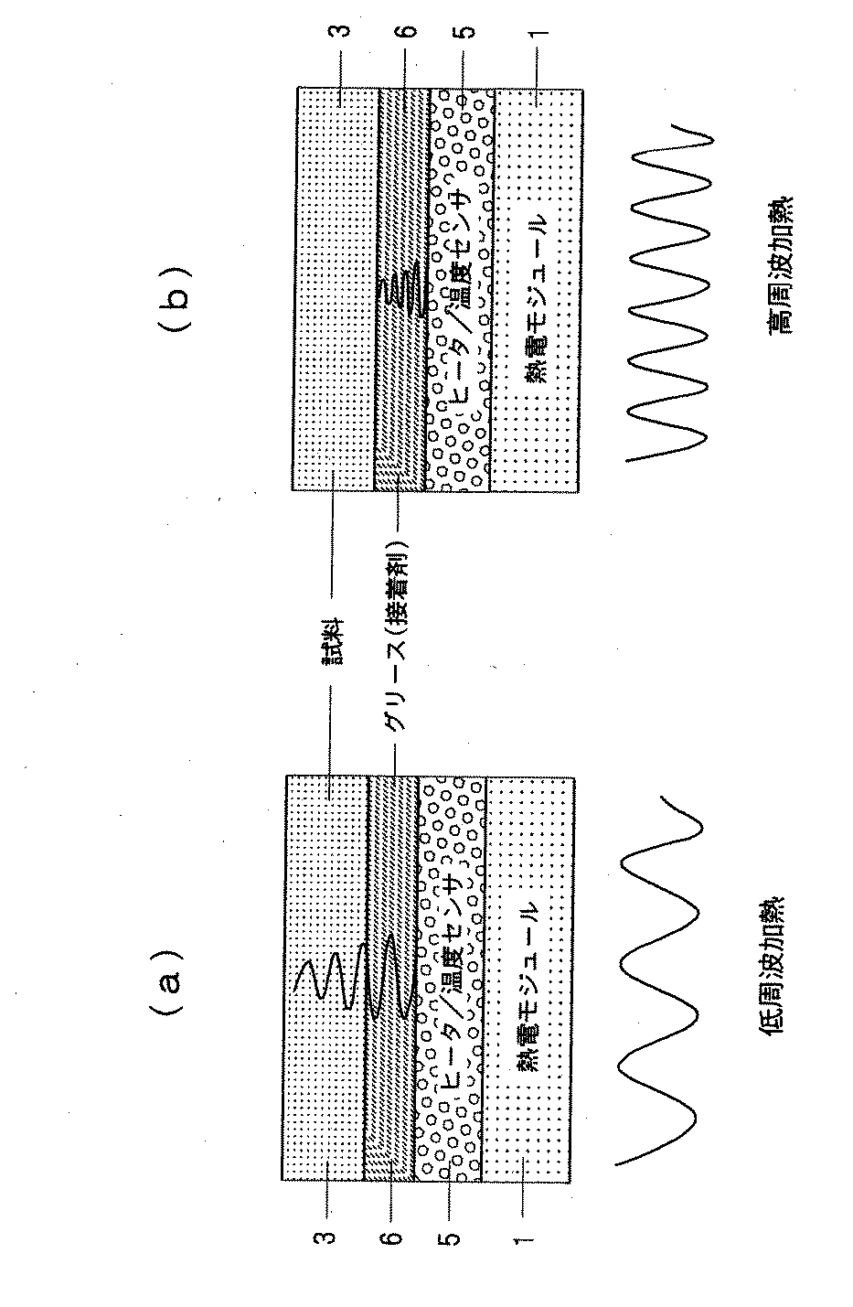
図2には試料を接着剤またはグリースにてヒータに接着する場合、この接着剤またはグリースの熱物性を評価して、試料の熱物性をより正確に求める手法を示す。図2に示す例においては、同図(b)に示すように平板状のヒータ兼温度センサ5を高周波の電流で加熱すると、熱の拡散はほぼグリース(接着剤)6内に留まり、グリース(接着剤)6の熱物性を反映した温度応答を測定することができる。逆に、同図(a)に示すように平板状のヒータ兼温度センサ5を低周波の電流で加熱した場合、熱はグリース(接着剤)6を通して試料3に拡散し、試料3の裏面に到達するので、グリース(接着剤)6と試料3の熱物性を反映した温度応答を測定することができる。
FIG. 2 shows a method for more accurately obtaining the thermal property of the sample by evaluating the thermal property of the adhesive or grease when the sample is bonded to the heater with an adhesive or grease. In the example shown in FIG. 2, when the flat heater /
それにより、高周波の電流で加熱したときに求めた接着剤またはグリースの熱物性を用いて測定値を補正することにより、試料3の熱物性値を正確に求めることができる。図2に示す例においても、図1(a)のようにヒータ2を用い、温度センサ4で温度を測定することによっても試料の熱物性値を求めることができるのは前記と同様である。
Accordingly, the thermophysical value of the
図3には標準試料を基準して被測定試料の熱物性値を求める方法を示す。即ち、熱電モジュール1上に設置したヒータ2の表面に、底面積が等しい標準試料Aと被測定試料Bとを設置する。標準試料Aは熱容量(CA)が既知であり、被測定試料Bの熱容量(CB)が未知であるとき、ヒータ2を前記と同様に周期加熱し、そのときの温度応答を観測する。標準試料の熱容量が既知なので、平板状ヒータを周期加熱した時のそれぞれの温度応答(振幅差、位相差)を求めることにより、被測定試料の熱容量を求めることができる。即ち前記本発明の原理で述べたとおり、それぞれの振幅をPA、PB 、位相差をδA、δBとすると、熱容量の比CB/CAはPB/PAとδA、δBの関数として前記式(6)によって求めることができる。
FIG. 3 shows a method for obtaining the thermophysical value of the sample to be measured with reference to the standard sample. That is, the standard sample A and the sample B to be measured having the same bottom area are installed on the surface of the
図4には本発明による熱物性測定装置のブロック図を示す。試料3は増幅器16で発生する交流加熱電流が供給されるヒータ2によって周期加熱され、且つ熱電モジュール1によって冷却され、そのときの温度変化を温度センサ4によって測定して、平均温度が一定となるように熱電モジュール1を制御する。ファンクションジェネレータ13で発生させた所定の交流信号を増幅器16で増幅し、試料3の加熱電流として後述する参照信号として用いる。
FIG. 4 shows a block diagram of a thermophysical property measuring apparatus according to the present invention. The
温度センサ4の測定信号はロックインアンプ12に伝えられ、またファンクションジュネレータ13による所定の受信信号を参照信号としてロックインアンプ12に出力する。ロックインアンプ12では、検出した信号のうちファンクションジュネレータ13の前記参照信号に同期した成分を増幅し、参照信号に対する位相遅れデータを得る。得られた結果をパーソナルコンピュータ14における演算部15にてデータ解析し、熱拡散率や熱容量との熱物性値の測定を行い、パーソナルコンピュータ14に表示する。このとき、演算部15には温度調節器11で設定している定常温度を入力し、測定した熱物性値のバックデータとする。
The measurement signal of the temperature sensor 4 is transmitted to the lock-in
1 熱電モジュール
2 ヒータ
3 試料
4 温度センサ
5 ヒータ兼温度センサ
1
Claims (2)
ヒータと同一位置またはヒータから一定距離の位置に設置した温度センサにより試料の温度応答を求め、
前記試料の温度応答によって試料の熱拡散率、比熱容量、熱伝導率の少なくともいずれかを求める熱物性測定方法において、
前記熱電モジュールの表面に前記平板状ヒータを設置して試料を周期加熱し、前記平板状ヒータの平均発熱量と等しい吸熱を前記熱電モジュールにより行わせて、試料の平均温度を一定に保ち、
前記ヒータに角周波数ωの電流を流して、ヒータの温度応答をヒータ両端間の交流電圧の3ω成分から測定し、
前記試料と前記温度センサとをグリースまたは接着剤により熱的に接触させて、高周波の周期加熱によりグリースまたは接着剤の熱物性値を測定し、
低周波の周期加熱により観測されるグリースまたは接着剤の熱物性値と試料の熱物性値の両者の寄与に基づく信号から、グリースまたは接着剤の熱物性の寄与を補正することにより、試料の熱物性値を求めることを特徴とする熱物性測定方法。 The sample is periodically heated using a thermoelectric module and a flat heater,
Obtain the temperature response of the sample with a temperature sensor installed at the same position as the heater or at a fixed distance from the heater,
In the thermophysical property measurement method for obtaining at least one of the thermal diffusivity, specific heat capacity, and thermal conductivity of the sample by the temperature response of the sample ,
The plate heater is installed on the surface of the thermoelectric module to periodically heat the sample, and the thermoelectric module performs heat absorption equal to the average calorific value of the plate heater to keep the average temperature of the sample constant,
A current with an angular frequency ω is passed through the heater, and the temperature response of the heater is measured from the 3ω component of the AC voltage across the heater,
The sample and the temperature sensor are brought into thermal contact with grease or an adhesive, and the thermal property value of the grease or adhesive is measured by high-frequency periodic heating,
By correcting the contribution of the thermal properties of the grease or adhesive from the signal based on the contribution of both the thermal properties of the grease or adhesive and the thermal properties of the sample observed by low-frequency periodic heating, A thermophysical property measuring method characterized by obtaining a physical property value .
ヒータと同一位置またはヒータから一定距離の位置に設置した温度センサと、
前記温度センサにより求めた温度応答から、試料の熱拡散率、比熱容量、熱伝導率の少なくともいずれかを求める演算手段とを備えた熱物性測定装置において、
前記熱電モジュールの表面に平板状ヒータを設置して、前記平板状ヒータを周期加熱し、
前記平板状ヒータの平均発熱量と等しい吸熱を前記熱電モジュールにより行わせて、試料の平均温度を一定に保ち、
前記ヒータに角周波数ωの電流を流して、ヒータの温度応答をヒータ両端間の交流電圧の3ω成分から測定し、
前記試料と温度センサをグリースまたは接着剤により熱的に接触させて、前記演算手段では高周波の周期加熱によりグリースまたは接着剤の熱物性値を測定し、低周波の周期加熱により観測されるグリースまたは接着剤の熱物性値と試料の熱物性値の両者の寄与に基づく信号から、グリースまたは接着剤の熱物性の寄与を補正することにより、試料の熱物性値を求めることを特徴とする熱物性測定装置。 Heating means for periodically heating the sample with a thermoelectric module and a flat heater;
A temperature sensor installed at the same position as the heater or at a fixed distance from the heater;
In the thermophysical property measuring apparatus comprising a calculation means for obtaining at least one of the thermal diffusivity, specific heat capacity, and thermal conductivity of the sample from the temperature response obtained by the temperature sensor ,
Installing a flat heater on the surface of the thermoelectric module, periodically heating the flat heater,
The thermoelectric module performs heat absorption equal to the average calorific value of the flat heater to keep the average temperature of the sample constant,
A current with an angular frequency ω is passed through the heater, and the temperature response of the heater is measured from the 3ω component of the AC voltage across the heater,
The sample and the temperature sensor are brought into thermal contact with grease or an adhesive, and the arithmetic means measures the thermal property value of the grease or adhesive by high-frequency periodic heating, and the grease or Thermophysical property of a sample is obtained by correcting the contribution of the thermal property of grease or adhesive from the signal based on the contribution of both the thermal property value of the adhesive and the sample. measuring device.
Priority Applications (1)
| Application Number | Priority Date | Filing Date | Title |
|---|---|---|---|
| JP2005286091A JP4258667B2 (en) | 2005-09-30 | 2005-09-30 | Thermophysical property measuring method and apparatus |
Applications Claiming Priority (1)
| Application Number | Priority Date | Filing Date | Title |
|---|---|---|---|
| JP2005286091A JP4258667B2 (en) | 2005-09-30 | 2005-09-30 | Thermophysical property measuring method and apparatus |
Publications (2)
| Publication Number | Publication Date |
|---|---|
| JP2007093509A JP2007093509A (en) | 2007-04-12 |
| JP4258667B2 true JP4258667B2 (en) | 2009-04-30 |
Family
ID=37979398
Family Applications (1)
| Application Number | Title | Priority Date | Filing Date |
|---|---|---|---|
| JP2005286091A Expired - Lifetime JP4258667B2 (en) | 2005-09-30 | 2005-09-30 | Thermophysical property measuring method and apparatus |
Country Status (1)
| Country | Link |
|---|---|
| JP (1) | JP4258667B2 (en) |
Cited By (1)
| Publication number | Priority date | Publication date | Assignee | Title |
|---|---|---|---|---|
| CN102288642A (en) * | 2011-08-29 | 2011-12-21 | 舟山市博远科技开发有限公司 | Concrete thermal diffusivity measurement device |
Families Citing this family (6)
| Publication number | Priority date | Publication date | Assignee | Title |
|---|---|---|---|---|
| JP5078703B2 (en) * | 2008-03-31 | 2012-11-21 | 日本モレックス株式会社 | Apparatus and method for measuring thermal conductivity of thermal bonding material |
| JP5362465B2 (en) * | 2009-06-17 | 2013-12-11 | 株式会社アイフェイズ | Thermal conductivity measuring method and thermal conductivity measuring device |
| CN102565123B (en) * | 2011-12-16 | 2014-01-08 | 四川大学 | Adiabatic Compression Measuring Air Specific Heat Capacity Ratio and Data Correction Method |
| CN103575759B (en) * | 2012-08-03 | 2015-12-02 | 香港纺织及成衣研发中心有限公司 | Flexible material compression dynamic heat transfer characteristic measuring equipment and measuring method |
| CN103063700B (en) * | 2012-11-06 | 2015-03-18 | 广东电网公司电力科学研究院 | Method for synchronously measuring apparent thermophysical property and autoignition temperature of combustible particles |
| CN107525821A (en) * | 2017-09-27 | 2017-12-29 | 山东省地矿工程集团有限公司 | Live thermal property tester caliberating device and method |
Family Cites Families (7)
| Publication number | Priority date | Publication date | Assignee | Title |
|---|---|---|---|---|
| JPS5245518B2 (en) * | 1972-09-11 | 1977-11-16 | ||
| JP3315368B2 (en) * | 1998-08-03 | 2002-08-19 | ニチアス株式会社 | Thermal conductivity measuring device and measuring method |
| JP4658366B2 (en) * | 2001-04-05 | 2011-03-23 | アルバック理工株式会社 | Thermophysical property measurement method |
| JP3858660B2 (en) * | 2001-10-10 | 2006-12-20 | 株式会社日立製作所 | Measuring method of thermal resistance of resin |
| JP3706911B2 (en) * | 2002-05-08 | 2005-10-19 | 国立大学法人東京工業大学 | Apparatus and method for simultaneous measurement of heat capacity spectroscopy and dielectric constant |
| JP4083127B2 (en) * | 2004-02-10 | 2008-04-30 | ニチアス株式会社 | Thermal conductivity measuring device and thermal conductivity measuring method |
| JP4195935B2 (en) * | 2004-03-01 | 2008-12-17 | 独立行政法人産業技術総合研究所 | Thermophysical property measuring method and apparatus |
-
2005
- 2005-09-30 JP JP2005286091A patent/JP4258667B2/en not_active Expired - Lifetime
Cited By (1)
| Publication number | Priority date | Publication date | Assignee | Title |
|---|---|---|---|---|
| CN102288642A (en) * | 2011-08-29 | 2011-12-21 | 舟山市博远科技开发有限公司 | Concrete thermal diffusivity measurement device |
Also Published As
| Publication number | Publication date |
|---|---|
| JP2007093509A (en) | 2007-04-12 |
Similar Documents
| Publication | Publication Date | Title |
|---|---|---|
| JP7477500B2 (en) | Steady-state thermoreflectance method and system for measuring thermal conductivity - Patents.com | |
| Albatici et al. | Assessment of the thermal emissivity value of building materials using an infrared thermovision technique emissometer | |
| US6676287B1 (en) | Direct thermal conductivity measurement technique | |
| US20120003726A1 (en) | Apparatus and method for calibration of non-contact thermal sensors | |
| Sadat et al. | Resistance thermometry-based picowatt-resolution heat-flow calorimeter | |
| Chaffar et al. | Thermal characterization of homogeneous walls using inverse method | |
| JP4505842B2 (en) | Thermal conductivity measuring method and apparatus, and gas component ratio measuring apparatus | |
| Kuntner et al. | Simultaneous thermal conductivity and diffusivity sensing in liquids using a micromachined device | |
| WO2009107209A1 (en) | Heater device, measuring device, and method of estimating heat conductivity | |
| CN104155336A (en) | Method and system for simultaneously measuring heat conductivity, heat diffusivity and heat capacity of low-dimensional material | |
| CN109997032B (en) | Thermal conductivity measuring device, thermal conductivity measuring method, and vacuum degree evaluating device | |
| JP4258667B2 (en) | Thermophysical property measuring method and apparatus | |
| CN103558247B (en) | A kind of Automatic thermal conductivity coefficient measurement equipment based on thermoelectric semiconductor | |
| CN117849100A (en) | Calibration Methods for Differential Scanning Calorimeters | |
| Ishizaki et al. | Microscale mapping of thermal contact resistance using lock-in thermography | |
| KR20140075757A (en) | Method for detecting heat generation points and device for detecting heat generate points | |
| JP2005345385A (en) | Characteristic measuring instrument and characteristic measuring method | |
| US8457918B2 (en) | Method and device for estimating the temperature sensed upon contact with a surface | |
| JP7323108B2 (en) | Thermoelectric property evaluation unit, thermoelectric property evaluation device, and thermoelectric property evaluation method | |
| CN108918580A (en) | A kind of lossless steady heat conduction rate measurement method | |
| JP2013228269A (en) | Heat flux measuring apparatus and heat flux measuring method | |
| JP2009068909A (en) | Thin film thermophysical property measuring method and thin film thermophysical property measuring device | |
| JP6634546B2 (en) | Thermal conductivity measuring device, thermal conductivity measuring method, and vacuum degree evaluation device | |
| JP2006071565A (en) | Inspection method and inspection device for thermal insulation performance in thermal insulation materials | |
| Zhang et al. | Thermal measurement and analysis of micro hotplate array using thermography |
Legal Events
| Date | Code | Title | Description |
|---|---|---|---|
| A621 | Written request for application examination |
Free format text: JAPANESE INTERMEDIATE CODE: A621 Effective date: 20070314 |
|
| A977 | Report on retrieval |
Free format text: JAPANESE INTERMEDIATE CODE: A971007 Effective date: 20081001 |
|
| A131 | Notification of reasons for refusal |
Free format text: JAPANESE INTERMEDIATE CODE: A131 Effective date: 20081028 |
|
| A521 | Request for written amendment filed |
Free format text: JAPANESE INTERMEDIATE CODE: A523 Effective date: 20081226 |
|
| TRDD | Decision of grant or rejection written | ||
| A01 | Written decision to grant a patent or to grant a registration (utility model) |
Free format text: JAPANESE INTERMEDIATE CODE: A01 Effective date: 20090127 |
|
| A01 | Written decision to grant a patent or to grant a registration (utility model) |
Free format text: JAPANESE INTERMEDIATE CODE: A01 |
|
| A61 | First payment of annual fees (during grant procedure) |
Free format text: JAPANESE INTERMEDIATE CODE: A61 Effective date: 20090127 |
|
| FPAY | Renewal fee payment (event date is renewal date of database) |
Free format text: PAYMENT UNTIL: 20120220 Year of fee payment: 3 |
|
| R150 | Certificate of patent or registration of utility model |
Ref document number: 4258667 Country of ref document: JP Free format text: JAPANESE INTERMEDIATE CODE: R150 Free format text: JAPANESE INTERMEDIATE CODE: R150 |
|
| FPAY | Renewal fee payment (event date is renewal date of database) |
Free format text: PAYMENT UNTIL: 20130220 Year of fee payment: 4 |
|
| R250 | Receipt of annual fees |
Free format text: JAPANESE INTERMEDIATE CODE: R250 |
|
| FPAY | Renewal fee payment (event date is renewal date of database) |
Free format text: PAYMENT UNTIL: 20130220 Year of fee payment: 4 |
|
| FPAY | Renewal fee payment (event date is renewal date of database) |
Free format text: PAYMENT UNTIL: 20130220 Year of fee payment: 4 |
|
| FPAY | Renewal fee payment (event date is renewal date of database) |
Free format text: PAYMENT UNTIL: 20130220 Year of fee payment: 4 |
|
| FPAY | Renewal fee payment (event date is renewal date of database) |
Free format text: PAYMENT UNTIL: 20140220 Year of fee payment: 5 |
|
| R250 | Receipt of annual fees |
Free format text: JAPANESE INTERMEDIATE CODE: R250 |
|
| FPAY | Renewal fee payment (event date is renewal date of database) |
Free format text: PAYMENT UNTIL: 20140220 Year of fee payment: 5 |
|
| FPAY | Renewal fee payment (event date is renewal date of database) |
Free format text: PAYMENT UNTIL: 20140220 Year of fee payment: 5 |
|
| R250 | Receipt of annual fees |
Free format text: JAPANESE INTERMEDIATE CODE: R250 |
|
| R250 | Receipt of annual fees |
Free format text: JAPANESE INTERMEDIATE CODE: R250 |
|
| S533 | Written request for registration of change of name |
Free format text: JAPANESE INTERMEDIATE CODE: R313533 |
|
| R350 | Written notification of registration of transfer |
Free format text: JAPANESE INTERMEDIATE CODE: R350 |
|
| R250 | Receipt of annual fees |
Free format text: JAPANESE INTERMEDIATE CODE: R250 |
|
| R250 | Receipt of annual fees |
Free format text: JAPANESE INTERMEDIATE CODE: R250 |
|
| R250 | Receipt of annual fees |
Free format text: JAPANESE INTERMEDIATE CODE: R250 |
|
| R250 | Receipt of annual fees |
Free format text: JAPANESE INTERMEDIATE CODE: R250 |
|
| R250 | Receipt of annual fees |
Free format text: JAPANESE INTERMEDIATE CODE: R250 |
|
| R250 | Receipt of annual fees |
Free format text: JAPANESE INTERMEDIATE CODE: R250 |
|
| R250 | Receipt of annual fees |
Free format text: JAPANESE INTERMEDIATE CODE: R250 |
|
| R250 | Receipt of annual fees |
Free format text: JAPANESE INTERMEDIATE CODE: R250 |
|
| R250 | Receipt of annual fees |
Free format text: JAPANESE INTERMEDIATE CODE: R250 |
|
| R250 | Receipt of annual fees |
Free format text: JAPANESE INTERMEDIATE CODE: R250 |
|
| EXPY | Cancellation because of completion of term |