JP4251592B2 - Surface light source device and reflection type liquid crystal display device - Google Patents
Surface light source device and reflection type liquid crystal display device Download PDFInfo
- Publication number
- JP4251592B2 JP4251592B2 JP30261999A JP30261999A JP4251592B2 JP 4251592 B2 JP4251592 B2 JP 4251592B2 JP 30261999 A JP30261999 A JP 30261999A JP 30261999 A JP30261999 A JP 30261999A JP 4251592 B2 JP4251592 B2 JP 4251592B2
- Authority
- JP
- Japan
- Prior art keywords
- light
- light source
- guide plate
- light guide
- liquid crystal
- Prior art date
- Legal status (The legal status is an assumption and is not a legal conclusion. Google has not performed a legal analysis and makes no representation as to the accuracy of the status listed.)
- Expired - Fee Related
Links
Images


Classifications
-
- G—PHYSICS
- G02—OPTICS
- G02F—OPTICAL DEVICES OR ARRANGEMENTS FOR THE CONTROL OF LIGHT BY MODIFICATION OF THE OPTICAL PROPERTIES OF THE MEDIA OF THE ELEMENTS INVOLVED THEREIN; NON-LINEAR OPTICS; FREQUENCY-CHANGING OF LIGHT; OPTICAL LOGIC ELEMENTS; OPTICAL ANALOGUE/DIGITAL CONVERTERS
- G02F1/00—Devices or arrangements for the control of the intensity, colour, phase, polarisation or direction of light arriving from an independent light source, e.g. switching, gating or modulating; Non-linear optics
- G02F1/01—Devices or arrangements for the control of the intensity, colour, phase, polarisation or direction of light arriving from an independent light source, e.g. switching, gating or modulating; Non-linear optics for the control of the intensity, phase, polarisation or colour
- G02F1/13—Devices or arrangements for the control of the intensity, colour, phase, polarisation or direction of light arriving from an independent light source, e.g. switching, gating or modulating; Non-linear optics for the control of the intensity, phase, polarisation or colour based on liquid crystals, e.g. single liquid crystal display cells
- G02F1/133—Constructional arrangements; Operation of liquid crystal cells; Circuit arrangements
- G02F1/1333—Constructional arrangements; Manufacturing methods
- G02F1/1335—Structural association of cells with optical devices, e.g. polarisers or reflectors
-
- G—PHYSICS
- G02—OPTICS
- G02B—OPTICAL ELEMENTS, SYSTEMS OR APPARATUS
- G02B6/00—Light guides; Structural details of arrangements comprising light guides and other optical elements, e.g. couplings
- G02B6/0001—Light guides; Structural details of arrangements comprising light guides and other optical elements, e.g. couplings specially adapted for lighting devices or systems
- G02B6/0011—Light guides; Structural details of arrangements comprising light guides and other optical elements, e.g. couplings specially adapted for lighting devices or systems the light guides being planar or of plate-like form
- G02B6/0033—Means for improving the coupling-out of light from the light guide
- G02B6/0035—Means for improving the coupling-out of light from the light guide provided on the surface of the light guide or in the bulk of it
- G02B6/0038—Linear indentations or grooves, e.g. arc-shaped grooves or meandering grooves, extending over the full length or width of the light guide
-
- G—PHYSICS
- G02—OPTICS
- G02B—OPTICAL ELEMENTS, SYSTEMS OR APPARATUS
- G02B6/00—Light guides; Structural details of arrangements comprising light guides and other optical elements, e.g. couplings
- G02B6/0001—Light guides; Structural details of arrangements comprising light guides and other optical elements, e.g. couplings specially adapted for lighting devices or systems
- G02B6/0011—Light guides; Structural details of arrangements comprising light guides and other optical elements, e.g. couplings specially adapted for lighting devices or systems the light guides being planar or of plate-like form
- G02B6/0013—Means for improving the coupling-in of light from the light source into the light guide
- G02B6/0023—Means for improving the coupling-in of light from the light source into the light guide provided by one optical element, or plurality thereof, placed between the light guide and the light source, or around the light source
- G02B6/0028—Light guide, e.g. taper
-
- G—PHYSICS
- G02—OPTICS
- G02B—OPTICAL ELEMENTS, SYSTEMS OR APPARATUS
- G02B6/00—Light guides; Structural details of arrangements comprising light guides and other optical elements, e.g. couplings
- G02B6/0001—Light guides; Structural details of arrangements comprising light guides and other optical elements, e.g. couplings specially adapted for lighting devices or systems
- G02B6/0011—Light guides; Structural details of arrangements comprising light guides and other optical elements, e.g. couplings specially adapted for lighting devices or systems the light guides being planar or of plate-like form
- G02B6/0066—Light guides; Structural details of arrangements comprising light guides and other optical elements, e.g. couplings specially adapted for lighting devices or systems the light guides being planar or of plate-like form characterised by the light source being coupled to the light guide
- G02B6/007—Incandescent lamp or gas discharge lamp
- G02B6/0071—Incandescent lamp or gas discharge lamp with elongated shape, e.g. tube
Landscapes
- Physics & Mathematics (AREA)
- General Physics & Mathematics (AREA)
- Optics & Photonics (AREA)
- Nonlinear Science (AREA)
- Mathematical Physics (AREA)
- Chemical & Material Sciences (AREA)
- Crystallography & Structural Chemistry (AREA)
- Planar Illumination Modules (AREA)
- Liquid Crystal (AREA)
- Devices For Indicating Variable Information By Combining Individual Elements (AREA)
- Light Guides In General And Applications Therefor (AREA)
Description
【0001】
【発明の技術分野】
本発明は、光の利用効率に優れて明るくて見易い反射型液晶表示装置を形成しうるフロントライトシステム用の面光源装置に関する。
【0002】
【発明の背景】
反射型液晶表示装置の暗部等での視認を可能とする面光源装置が求められている中、本発明者は透過型液晶表示装置に用いられているバックライト式面光源装置を液晶セルの視認側に配置するフロントライトシステムの適用を試みた。かかるバックライト式面光源装置は、側面からの入射光を光出射手段を介し上下面の一方より出射する導光板を使用したものであり、フロントライトシステムではその導光板を介して表示内容を視認することとなる。
【0003】
しかし従来のバックライト用導光板による面光源装置では、点灯時におけるコントラスト不足や消灯時における明るさ不足に加えて、導光板を介した表示像が著しく乱れて明瞭さに乏しく実用が困難な問題点があった。かかるコントラスト不足や表示の乱れは、拡散層等を介した表示光の散乱によるところが大きい。
【0004】
前記に鑑みて本発明者は、散乱光の発生を抑制した面光源装置とし、それをフロントライトシステムに用いてコントラスト不足や表示乱れの防止を試みた。しかしながらその場合には、光の拡散による輝度の平準化効果が失われるため面光源装置に明暗差が発生し、暗部が形成されて表示像に部分的な欠落問題の生じることが判明した。
【0005】
【発明の技術的課題】
本発明は、消灯時及び点灯時の視認におけるコントラストに優れ、表示の明るさにも優れると共に、導光板を介した表示像が乱れにくくて明瞭性に優れ、かつ表示像の部分的な欠落を生じない反射型液晶表示装置を形成しうるフロントライトシステム用の面光源装置の開発を課題とする。
【0006】
【課題の解決手段】
本発明は、入射側面からの入射光を上面に形成した光出射手段を介して下面より出射し、かつ下面からの入射光が上面より透過する導光板の前記入射側面に、その面の長手方向の長さよりも有効発光領域の長さが大きい線状光源を配置してなり、前記導光板の下面側で形成された情報光をその導光板の上面側より透視するためのフロントライトシステム用の面光源装置であり、
導光板における光出射手段が短辺面と長辺面からなるプリズム状凹凸の50μ m 〜1.0 mm ピッチの繰返し構造よりなり、かつ前記短辺面が下面の基準平面に対し30〜45度の傾斜角で入射側面側よりその対向端側に下り傾斜する斜面からなると共に、前記長辺面が当該基準平面に対し0〜10度の傾斜角範囲にあってその全体の角度差が5度以内であり、最寄りの長辺面間における傾斜角差が1度以内で、しかも当該基準平面に対する投影面積が短辺面のそれの5倍以上である斜面からなり、
導光板の光出射手段を形成するプリズム状凹凸の稜線が入射側面の基準平面に対し±30度以内の傾斜範囲にあり、
入射側面に対するプリズム状凹凸の稜線の傾斜角をθ、入射側面と線状光源の先端面との間隔をdとしたとき、導光板におけるプリズム状凹凸の稜線が線状光源より遠離る側に基づいてその端面よりも、線状光源の有効発光領域の端が式:1 mm +d・ sin θ+d/2による算出値以上に突出した状態にある面光源装置、及びその面光源装置における下面側に、反射層を具備する液晶セルを有する反射型液晶表示装置を提供するものである。
【0007】
【発明の効果】
本発明によれば、光の利用効率に優れ明るさの均一性に優れるフロントライトシステム用の面光源装置を得ることができ、消灯時及び点灯時の視認におけるコントラストに優れ、表示の明るさにも優れると共に、導光板を介した表示像が乱れにくくて明瞭性に優れ、かつ暗部の発生による表示像の部分的な欠落問題を生じない表示品位に優れる反射型液晶表示装置を得ることができる。
【0008】
【発明の実施形態】
本発明による面光源装置は、入射側面からの入射光を上面に形成した光出射手段を介して下面より出射し、かつ下面からの入射光が上面より透過する導光板の前記入射側面に、その面の長手方向の長さよりも有効発光領域の長さが大きい線状光源を配置してなり、前記導光板の下面側で形成された情報光をその導光板の上面側より透視するためのフロントライトシステム用のものである。図1にその面光源装置1の例を示した。11が導光板、12が線状光源である。なお図は反射型液晶表示装置としたものを示しており、2が液晶表示パネル、21が反射層である。
【0009】
導光板としては、入射側面からの入射光を上面に形成した光出射手段を介して下面より出射するものが用いられ、一般には図1に例示の如く上面11a、それに対向する下面11b及び上下面間の側面からなる入射側面11cを有する板状物よりなる。板状物は、図例の如く同厚型のものであってもよいし、入射側面に対向する対向端11dの厚さを入射側面のそれよりも薄くした楔形等の形態を有するものであってもよい。対向端の薄型化は、軽量化や上面の光出射手段への入射側面からの入射光の入射効率の向上などの点より有利である。
【0010】
導光板の上面に形成する光出射手段は、入射側面からの入射光を上面を介して下面より指向性よく効率的に出射させ、かつ下面からの入射光を上面より散乱なく効率よく透過させる点などよりは、入射側面と対面する斜面を有する光出射手段、就中、下面の基準平面に対する傾斜角が30〜45度の斜面と10度以下の平坦面からなる凹凸の繰返し構造からなる光出射手段である。
【0011】
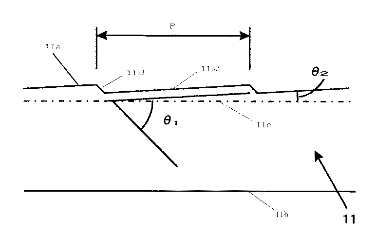
前記凹凸の繰返し構造は、光の利用効率や前記した下面よりの出射光を反射層で反転させて上面より正面(垂直)方向に指向性よく出射させる点などより、図2の例の如く下面11bの基準平面11eに対する傾斜角(θ 1 )が30〜45度で入射側面11cの側よりその対向端11dの側に下り傾斜する短辺面11a1 と、当該傾斜角(θ 2 )が0〜10度の長辺面11a2 からなるプリズム状凹凸の繰返し構造よりなるものである。なお凸部又は凹部は、短辺面及び長辺面等とその形成面との交点を結ぶ直線に基づき、短辺面及び長辺面等の交点(頂点)が当該直線よりも突出しているか(凸)、窪んでいるか(凹)による。
【0012】
前記のプリズム状凹凸において短辺面11a1は、側面よりの入射光の内その面に入射する光を反射して下面11bに供給する役割をする。その場合、短辺面の傾斜角θ1を30〜45度とすることにより伝送光を下面に対し垂直性よく反射し、ひいては図1による反射層21を介して正面への指向性に優れる出射光(照明光)を効率よく得ることができ、明るい表示を達成することができる。
【0013】
正面への指向性等の点より短辺面の好ましい傾斜角θ1は、導光板内部を伝送される光のスネルの法則による屈折に基づく全反射条件が例えば屈折率1.5では±41.8度であることなどを考慮して32〜44度、就中33〜43度、特に35〜42度である。なお全反射条件を満足せずに短辺面を透過して漏れ光となる一部の光は、正面方向に対し60度以上の大きい角度で出射して正面方向近傍の視認に影響しにくいが、傾斜角θ1が45度を超えると上面11aよりの漏れ光が増大しやすくなり光利用効率の点で不利となる。
【0014】
一方、長辺面11a2は、それに入射する伝送光を反射して短辺面に供給すると共に、前記した短辺面による反射光を反射層21を介し反転させて上面11aより透過させること、及び反射モードでの外光を入射させてそれを反射層21を介し反射させて上面11aより透過させることを目的とする。かかる点より下面の基準平面11eに対する長辺面の傾斜角θ2は、0〜10度であることが好ましい。
【0015】
長辺面の当該傾斜角θ2は0度(水平面)であってもよいが、0度超とすることで長辺面に入射した伝送光を反射して短辺面に供給する際に伝送光を平行光化することができ、短辺面を介した反射光の指向性を高めることができて、表示に有利となる。一方、当該傾斜角が10度を超えると長辺面への入射率が低下して対向端側への光供給が不足し発光が不均一化しやすくなり、屈折による光路変更も大きくなって正面方向の光量が低下し表示に不利となる。また導光板の断面形状においても対向端側の薄型化が困難となり、プリズム状凹凸への入射光量も減少して発光効率も低下しやすくなる。
【0016】
伝送光の平行光化による出射光の集光化や正面方向の光量増加、漏れ光の抑制等の前記性能などの点より長辺面の好ましい傾斜角θ2は、8度以下、就中5度以下である。上記の如く短辺面と長辺面の当該傾斜角を調節することにより、出射光に指向性をもたせることができ、それにより下面に対して垂直方向ないしそれに近い角度で光を出射させることが可能になる。
【0017】
導光板の長辺面を介した表示像の視認性などの点より好ましい長辺面は、その傾斜角θ2の角度差を導光板の全体で5度以内、就中4度以内、特に3度以内としたものであり、最寄りの長辺面間における傾斜角θ2の差を1度以内、就中0.3度以内、特に0.1度以内としたものである。これにより透過する長辺面の傾斜角θ2の相違等により表示像が受ける影響を抑制することができる。長辺面による透過角度の偏向が場所によって大きく相違すると不自然な表示像となり、特に近接画素の近傍における透過像の偏向差が大きいと著しく不自然な表示像となりやすい。
【0018】
前記した傾斜角θ2の角度差は、長辺面の傾斜角が上記した10度以下にあることを前提とする。すなわち、かかる小さい傾斜角θ2として長辺面透過時の屈折による表示像の偏向を抑制して許容値内とすることを前提とするものであり、これは観察点を垂直方向近傍に設定して最適化した液晶表示装置の最適視認方向を変化させないことを目的とする。表示像が偏向されると最適視認方向が垂直方向近傍からズレると共に、表示像の偏向が大きいと導光板上面からの漏れ光の出射方向に近付いてコントラストの低下などその影響を受けやすくなる場合もある。なお長辺面の傾斜角θ2を10度以下とする条件には、透過光の分散等の影響も無視できる程度のものとすることなども含まれている。
【0019】
また明るい表示像を得る点よりは、外光の入射効率に優れ、液晶セルによる表示像の透過光率ないし出射効率に優れるものが好ましい。かかる点より、下面の基準平面に対する長辺面の投影面積が短辺面のそれの5倍以上、就中10倍以上、特に15倍以上のプリズム状凹凸とすることが好ましい。これにより、液晶セルによる表示像の大部分を長辺面を介して透過させることができる。
【0020】
なお液晶セルによる表示像の透過に際して、短辺面に入射した表示像は入射側面側に反射されて上面より出射しないか、下面に対する法線を基準に長辺面透過の表示像とは反端側の大きく異なる方向に偏向されて出射し、長辺面を介した表示像に殆ど影響を及ぼさない。よって表示光の透過不足で不自然な表示となることを防止する点などより、画素と短辺面がオーバーラップする面積を小さくして長辺面を介した充分な光透過率を確保することが好ましい。
【0021】
一般に液晶セルの画素ピッチは100〜300μmであることを鑑みた場合、前記の点より短辺面は、下面の基準平面に対する投影幅に基づいて40μm以下となるように形成されていることが好ましい。なお短辺面の投影幅が小さくなるほどその形成に高度な技術が必要となり、プリズム状凹凸の頂部が一定以上の曲率半径からなる丸みをもつと散乱効果が現れて表示像の乱れの原因となりやすく、また一般に蛍光管のコヒーレント長が20μm程度とされている点などよりも短辺面の投影幅が小さくなると回折等による表示品位の低下原因となりやすいことなどより、特に好ましい短辺面の投影幅は1〜20μm、就中5〜15μmである。
【0022】
前記の点より短辺面の間隔は大きいことが好ましいが、一方で短辺面は上記したように側面入射光の実質的な出射機能部分であるから、その間隔が広すぎると点灯時の照明が疎となってやはり不自然な表示となる場合があり、それらを鑑みて、図2に例示した如くプリズム状凹凸の繰返しピッチPは、50μm〜1.0mmである。なおピッチは、一定であってもよいし、例えばランダムピッチや所定数のピッチ単位をランダム又は規則的に組合せたものなどの如く不規則であってもよい。
【0023】
プリズム状凹凸からなる光出射手段の場合、液晶セルの画素と干渉してモアレを生じる場合がある。モアレの防止は、プリズム状凹凸のピッチ調節で行いうるが、上記したようにプリズム状凹凸のピッチには好ましい範囲がある。従ってそのピッチ範囲でモアレが生じる場合の解決策が問題となる。
【0024】
本発明においては図3に例示の如く、画素に対してプリズム状凹凸を交差状態で配列しうるように、プリズム状凹凸を入射側面11cの基準平面に対し傾斜状態(θ)に形成してモアレを防止する方式が好ましい。その場合、傾斜角θが大きすぎると短辺面を介した反射に偏向を生じて出射光の方向に大きな偏りが発生し、導光板の光伝送方向における発光強度の異方性が大きくなって光利用効率も低下し、表示品位の低下原因となりやすい。
【0025】
前記の点より入射側面の基準平面に対するプリズム状凹凸の配列方向、すなわちプリズム状凹凸の稜線方向の傾斜角θは、±30度以内であり、就中±28度以内、特に±25度以内とすることが好ましい。なお、±の符号は入射側面を基準とした傾斜の方向を意味する。液晶セルの解像度が低くてモアレを生じない場合やモアレを無視しうる場合には、図4に例示の如くプリズム状凹凸の配列方向は入射側面に平行なほど好ましい(θ=0度)。
【0026】
導光板は、上記したように適宜な形態とすることができる。楔形等とする場合にもその形状は適宜に決定でき、直線面や曲面などの適宜な面形状とすることができる。また光出射手段を形成する斜面やプリズム状凹凸も直線面や屈折面や湾曲面等の適宜な面形態に形成されていてよい。さらにプリズム状等の凹凸は、ピッチに加えて形状等も異なる凹凸の組合せからなっていてもよい。加えてプリズム状等の凹凸は、稜線が連続した一連の凸部又は凹部として形成されていてもよいし、所定の間隔を有して稜線方向に不連続に配列した断続的な凸部又は凹部として形成されていてもよい。
【0027】
導光板における下面や入射側面の形状については、特に限定はなく、適宜に決定してよい。一般には可及的に平滑でフラットな下面及びその下面に対して垂直な入射側面とされる。入射側面については、例えば湾曲凹形などの線状光源の外周等に応じた形状として、入射光率の向上をはかることもできる。さらに線状光源との間に介在する導入部を有する入射側面構造などとすることもでき、その導入部は、線状光源などに応じて適宜な形状とすることができる。
【0028】
導光板は、線状光源の波長域に応じそれに透明性を示す適宜な材料にて形成しうる。ちなみに可視光域では、例えばアクリル系樹脂やポリカーボネート系樹脂、エポキシ系樹脂等で代表される透明樹脂やガラスなどがあげられる。複屈折を示さないか、複屈折の小さい材料で形成した導光板が好ましく用いられる。
【0029】
導光板は、切削法にても形成でき、適宜な方法で形成することができる。量産性等の点より好ましい製造方法としては、熱可塑性樹脂を所定の形状を形成しうる金型に加熱下に押付て形状を転写する方法、加熱溶融させた熱可塑性樹脂あるいは熱や溶媒を介して流動化させた樹脂を所定の形状に成形しうる金型に充填する方法、熱や紫外線ないし放射線等で重合処理しうる液状樹脂を所定の形状を形成しうる型に充填ないし流延して重合処理する方法などがあげられる。
【0030】
なお導光板は、例えば光の伝送を担う導光部にプリズム状凹凸等の光出射手段(上面)を形成したシートを接着したものの如く、同種又は異種の材料からなる部品の積層体などとして形成されていてもよく、1種の材料による一体的単層物として形成されている必要はない。
【0031】
導光板の厚さは、使用目的による導光板のサイズや線状光源の大きさなどにより適宜に決定することができる。液晶表示装置等の形成に用いる場合の一般的な厚さは、その入射側面に基づき10mm以下、就中0.1〜5mm、特に0.3〜3mmである。また明るい表示を達成する点などより好ましい導光板は、上下面方向の入射光、特に下面から上面への垂直入射光の全光線透過率が90%以上、就中92%以上、特に95%以上で、ヘイズが30%以下、就中15%以下、特に10%以下のものである。
【0032】
上記した導光板によれば、上面及び下面からの入射光が下面又は上面より良好に透過し、それを用いて精度よく平行化された光を視認に有利な垂直性に優れる方向に出射し、線状光源からの光を効率よく利用して明るさに優れる面光源装置、さらには上面よりの漏れ光が表示像と重複しにくく、消灯時及び点灯時の視認におけるコントラストに優れ表示の明るさにも優れると共に、導光板を介した表示像が乱れにくく明瞭性に優れて見やすく、表示品位に優れる低消費電力の反射型液晶表示装置などの種々の装置を形成することができる。
【0033】
本発明による面光源装置は、例えば図1の例の如く導光板11の下面側で形成された情報光をその導光板の上面側より透視するためのサイドライト型のフロントライトとして用いられるものであり、その形成は導光板の入射側面11cにその入射側面の長手方向の長さよりも有効発光領域の長さが大きい線状光源12を配置することにより行うことができる。
【0034】
前記において入射側面11cよりも有効発光領域の長さが大きい線状光源12の使用は、影の発生防止を目的とする。すなわち線状光源の長さが短いとそれが数mm程度のものであっても導光板端部での入射光量が少なくて不均一に発光したり、非発光領域が発生したりして点灯時に非常に明瞭な影が発生し、表示が非常に見にくくなるためその防止を目的とする。
【0035】
ちなみに線状光源の有効発光領域長が入射側面よりも短いと点灯時に正面方向にても影が発生する。その正面方向の影は、入射側面と同長の有効発光領域長とすることで防止しうるが、その場合でも斜視方向では影が発生する。その斜視による光を出射しない導光板部分に基づく影は、斜めに発生して表示部分を横切ることとなり正面方向の場合よりも目立つものとなる。
【0036】
前記した影の発生状態は、導光板の入射側面に対して線状光源を密接配置するか、間隔を設けて配置するかにて変化し、その間隔が大きくなるほど影の発生範囲が大きくなる。導光板の入射側面に対する線状光源の間隔を設けた配置は、密接配置では導光板との接触で線状光源が破損する恐れのある場合などにその防止を目的に必要に応じて行われる。
【0037】
また影の発生状態は、導光板における光出射手段としての凹凸の稜線が入射側面に対して傾斜するか否かや、その傾斜角によっても変化する。例えば図3において入射側面11cに対する凹凸の稜線の傾斜角をθとして稜線が入射側面に対して傾斜する場合(θ≠0)、その凹凸の稜線が線状光源より遠離る側11fにおいては正面方向にても斜視と同様に斜めに影が発生し、その影は入射側面の11f側端を始点に導光板の内側に向かうものである。そのため入射側面の他端側では影が外側に向かって延びるためその影響は少ない。
【0038】
従って有効発光領域に基づく線状光源の長さは、導光板の入射側面の長手方向の長さに加えて、上記した影の発生状態などにより決定される。導光板の入射側面に可及的に均一に光を入射させて正面方向及び実用的な斜視範囲、特に斜め30度の視野角範囲における影の発生を防止する点より、本発明では、図3に例示した如く前記の傾斜角θに加えて、入射側面11cと線状光源12の先端面との間隔をdとしたとき、導光板11の端面よりも線状光源の有効発光領域12Aの端は、式:1mm+d・sinθ+d/2による算出値以上に突出した状態にある。
【0039】
よって図4の例の如く前記θ=0の時、すなわち凹凸の稜線が入射側面に平行な場合には、1mm+d/2以上の突出長T2であることが好ましい。一方、図3の例の如くθ≠0の場合には、上記の如く導光板の一端の11f側において前記式による算出値以上の突出長T1であることが好ましい。なお図上の12Bは、電極等の非発光領域である。
【0040】
前記において、当該式による線状光源の突出長条件は、θ=0のときには左右対称であることより導光板の両端部で満足されていることが好ましいが、θ≠0のときには導光板の少なくとも当該11f側で満足されていることが好ましい。θ≠0のときの導光板の当該11f側でない側では、有効発光領域端が導光板の内側となる長さの線状光源にても影の発生を防止しうるときもあるが、その場合にても線状光源の全体における有効発光領域長は、2mm+d以上であることが好ましい。
【0041】
線状光源としては、適宜なものを用いうる。一般には例えば(冷,熱)陰極管等の線状光源、発光ダイオード等の点状光源を線状等に配列したアレイ体、あるいは点状光源を一定又は不定間隔の線状発光状態に変換する装置を用いた線状光源などが好ましく用いうる。低消費電力性や耐久性等の点よりは、冷陰極管が特に好ましい。
【0042】
面光源装置の形成に際しては、必要に応じて図1に例示した如く線状光源12からの発散光を導光板の入射側面11cに導くために線状光源を包囲する光源ホルダ13や反射防止層などの適宜な補助手段を配置した組合せ体とすることもできる。光源ホルダとしては、高反射率金属薄膜を付設した樹脂シートや金属箔などが一般に用いられる。光源ホルダを導光板の端部に接着剤等を介して接着する場合には、その接着部分については光出射手段の形成を省略することもできる。
【0043】
反射防止層は、表面反射の抑制を目的とし、例えば誘電体、フッ素含有のポリマーや低密度材料等による光学多層膜や屈折率層などの従来に準じた適宜な透明層として形成することができる。反射防止層は、導光板の上下面の一方又は両方に塗布方式や蒸着方式等の適宜な方式で直接設けられていてもよいし、反射防止層を透明基材で支持してそのシートを導光板の下面に粘着層等の適宜な接着手段を介し接着する方式などにより設けられていてもよく、その形成方式について特に限定はない。
【0044】
上記のように本発明による面光源装置は、光の利用効率に優れて明るくて垂直性に優れる光を提供し、大面積化等も容易であることより反射型液晶表示装置等におけるフロントライトシステムなどとして種々の装置に好ましく適用でき、明るくて見やすく低消費電力の反射型液晶表示装置等を得ることができる。なお面光源装置の点灯・消灯は適宜な方式にて行うことができる。
【0045】
図1に本発明による面光源装置1をフロントライトシステムに用いた反射型液晶表示装置を例示した。2が反射型の液晶表示パネルであり、22が液晶層、23がセル基板でこれらが液晶セルを形成し、24が偏光板、21が反射層である。反射型液晶表示装置は、図例の如く面光源装置の光出射側、すなわち導光板11の下面側に反射層を具備する液晶セルを配置することにより形成することができる。
【0046】
反射型液晶表示装置は一般に、液晶シャッタとして機能する透明電極具備の液晶セルとそれに付随の駆動装置、偏光板、フロントライト、反射層及び必要に応じての拡散層や補償用位相差板等の構成部品を適宜に組立てることなどにより形成される。本発明においては、上記した面光源装置をフロント側に用いる点を除いて特に限定はなく、従来に準じて形成することができる。なお図例では、透明電極の記入を省略している。
【0047】
従って用いる液晶セルについては特に限定はなく、例えば液晶の配向形態に基づく場合、TN液晶セルやSTN液晶セル、垂直配向セルやHANセル、OCBセルの如きツイスト系や非ツイスト系、ゲストホスト系や強誘電性液晶系の液晶セルなどの適宜なものを用いうる。また液晶の駆動方式についても特に限定はなく、例えばアクティブマトリクス方式やパッシブマトリクス方式などの適宜な駆動方式であってよい。
【0048】
反射型液晶表示装置では、反射層の配置が必須であるが、その配置位置については図1に例示の如く液晶表示パネル2の外側に設けることもできるし、セル基板に付設するなどして液晶セルの内側に設けることもできる。その反射層については、例えばアルミニウムや銀、金や銅やクロム等の高反射率金属の粉末をバインダ樹脂中に含有する塗工層や蒸着方式等による金属薄膜の付設層、その塗工層や付設層を基材で支持した反射シート、金属箔などの従来に準じた適宜な反射層として形成することができる。また液晶セルの内部に設ける反射層は、例えば透明導電膜などにて形成することができる。
【0049】
偏光板としては、適宜なものを用いうるが、高度な直線偏光の入射による良好なコントラスト比の表示を得る点などよりは、例えばヨウ素系や染料系の吸収型直線偏光子などの如く偏光度の高いものが好ましく用いうる。なお反射型液晶表示装置の形成に際しては、例えば拡散層や保護層、補償用の位相差板などの適宜な光学素子を適宜に配置することができる。その場合、拡散層としては表示像を乱さない程度の弱い拡散能を示すものが好ましく用いられる。
【0050】
一方、前記した補償用位相差板は、複屈折の波長依存性などを補償して視認性の向上等をはかることを目的とするものであり、視認側又は/及び背面側の偏光板と液晶セルの間等に必要に応じて配置される。補償用の位相差板としては、波長域などに応じて適宜なものを用いることができ、1層又は2層以上の位相差層の重畳層として形成されていてもよい。
【0051】
本発明による反射型液晶表示装置の視認は、面光源装置、特にその導光板の長辺面の透過光を介して行われる。すなわち面光源装置の点灯時には、導光板の下面より出射した光が偏光板と液晶層等を経由して反射層を介し反射され、液晶層と偏光板等を逆経由して導光板に至り長辺面を透過した表示像が視認される。その場合、強い漏れ光は液晶セルに対して垂直な正面方向とは角度が大きくズレた方向に出射し、正面方向に出射する漏れ光は弱いことから長辺面を介して正面方向の近傍で表示品位に優れる表示像を視認することができる。
【0052】
一方、面光源装置が消灯の外光を利用した場合においても、導光板の上面の長辺面より入射した光が偏光板や液晶層や反射層等を前記に準じ透過・逆経由して導光板に至り、長辺面を透過した表示像が正面方向の近傍で導光板による乱れ等が少ない表示品位に優れる状態で視認することができる。
【0053】
上記した面光源装置や液晶表示装置を形成する導光板や液晶セルや偏光板等の光学素子ないし部品は、全体的又は部分的に積層一体化されて固着されていてもよいし、分離容易な状態に配置されていてもよい。界面反射の抑制によるコントラストの低下防止などの点よりは、固着状態にあることが好ましく、少なくとも面光源装置における導光板の下面と液晶セルの上面が固着密着状態にあることが好ましい。その固着密着処理には、粘着剤等の適宜な透明接着剤を用いることができ、その透明接着層に透明粒子等を含有させて拡散機能を示す接着層などとすることもできる。
【0054】
【実施例】
例1
ダイヤモンドバイトにて表面を所定形状に切削して形成した金型中子を装着した金型を80℃に加温し、それに260℃で加熱溶融したポリメチルメタクリレートを充填して導光板を得た。この導光板は、幅40mm、奥行25mm、入射側面の厚さ1mm、対向端の厚さ0.6mmであり、上面及び下面は平坦で、上面に入射側面に平行なプリズム状凹凸(θ=0)を210μmのピッチで有し、短辺面の傾斜角が42.5〜43度の範囲、長辺面の傾斜角が1.8〜3.5度の範囲で変化し、最寄り長辺面の傾斜角変化が0.1度以内にあり、短辺面の下面に対する投影幅が10〜16μm、長辺面/短辺面の下面に対する投影面積比が12倍以上のものである。なおプリズム状凹凸は、入射側面より2mm離れた位置より形成した。
【0055】
前記導光板の下面側にTN型反射型液晶パネルを配置した後、その導光板の入射側面に有効発光領域の一端から30mmの位置に幅20mmの第1の黒テープ、他端から20mmの位置に幅20mmの第2の黒テープを巻付けた直径2mm、長さ195mmの冷陰極管(ウエスト電気社製)からな線状光源を密接配置し(d=0)、黒テープ間を銀反射シートからなるホルダにて包囲して線状光源にインバータと直流電源を接続し反射型液晶表示装置を得た。面光源装置は、その電源のオン/オフを介して点灯/消灯を設定することができる。
【0056】
前記の反射型液晶表示装置について、その点灯状態の線状光源の位置を左右に移動させて正面方向及び左右30度の斜視方向における影の発生状態を調べた。評価は、影の発生がない場合を○、弱い影が発生した場合を△、明瞭な影が発生した場合を×とした。なお線状光源の第1の黒テープの内側端が入射側面の左端と一致する位置を基準(0)として導光板の内側方向を−、外側方向を+とした。その結果を表1に示した。
【0057】
例2
厚さ2mmのスペーサと、導光板両側の当て板を介して入射側面より2mm離れた位置に線状光源を配置した(d=2)ほかは例1に準じて面光源装置と反射型液晶表示装置を得、その反射型液晶表示装置の影を調べた。その結果を表2に示した。
【0059】
例3
入射側面より4mm離れた位置に線状光源を配置した(d=4)ほかは例2に準じて面光源装置と反射型液晶表示装置を得、その反射型液晶表示装置の影を調べた。その結果を表3に示した。
【0061】
例4
例1に準じプリズム状凹凸の稜線を入射側面に対して23度の角度で右上がりに傾斜させた導光板(θ=23)を形成し、それを用いて面光源装置と反射型液晶表示装置を得、その反射型液晶表示装置の影を調べた。なおその場合、導光板の右端側についても線状光源の第2の黒テープの内側端が入射側面の右端と一致する位置を基準(0)として導光板の内側方向を−、外側方向を+として影の発生状態を調べた。その結果を表4に示した。
【0063】
例5
厚さ2mmのスペーサと、導光板両側の当て板を介して入射側面より2mm離れた位置に線状光源を配置した(d=2)ほかは例4に準じて面光源装置と反射型液晶表示装置を得、その反射型液晶表示装置の影を調べた。その結果を表5に示した。
【0065】
例6
入射側面より4mm離れた位置に線状光源を配置した(d=4)ほかは例5に準じて面光源装置と反射型液晶表示装置を得、その反射型液晶表示装置の影を調べた。その結果を表6に示した。
【0067】
上記した表1〜3よりθ=0(凹凸の稜線が平行)の条件では、1mm+d/2以上の突出長(T2)を持たせることで影の発生を防止できていることがわかり、導光板の右端側についても同様の結果が得られた。なお影が発生した場合において、その影は発光の著しい不均一さに基づき、表示を見にくくするものであった。
【0069】
一方、表4〜6よりθ≠0(凹凸の稜線の傾斜)の条件では、θ=0の場合と同様にd(導光板と光源間の距離)による影の発生状態の変化が現れると共に、表5,6と表2,3の対比より稜線が傾斜することで11f側における影の発生範囲が大きくなり、1mm+d・sinθ+d/2以上の突出長(T1)を持たせることで影の発生を防止できていることがわかる。
【0070】
一方、導光板の11f側と反対側の右端側については、有効発光領域が導光板の内側にあっても影の発生しないときもあるが(表4)、その場合にても導光板両サイド間の全体における影の発生を防止する点よりは、2mm+d以上の有効発光領域長さが求められることがわかる。なお上記においてdが大きくなるほど影発生の境界が判別しにくくなり、影自体も薄くなる傾向があった。
【0071】
他方、光源を消灯した外光照明では明瞭な表示を達成することができた。以上より、本発明による面光源装置を用いることにより、点灯時及び消灯時のいずれのときにも明るさの均一性に優れて明瞭な表示のフロントライト式反射型液晶表示装置の得られることがわかる。
【図面の簡単な説明】
【図1】反射型液晶表示装置例の側面説明図
【図2】導光板におけるプリズム状凹凸の側面説明図
【図3】線状光源配置例の説明図
【図4】他の線状光源配置例の説明図
【符号の説明】
1:面光源装置
11:導光板
11a:上面
11a1:短辺面
11a2:長辺面
11b:下面
11c:入射側面
12:線状光源
2:液晶表示パネル
21:反射層
22:液晶層
23:セル基板
24:偏光板[0001]
TECHNICAL FIELD OF THE INVENTION
INDUSTRIAL APPLICABILITY The present invention can form a reflective liquid crystal display device that is excellent in light utilization efficiency and easy to see.For front light systemThe present invention relates to a surface light source device.
[0002]
BACKGROUND OF THE INVENTION
While a surface light source device that enables visual recognition in a dark portion or the like of a reflective liquid crystal display device has been demanded, the present inventor has viewed a backlight type surface light source device used in a transmissive liquid crystal display device as a liquid crystal cell. An attempt was made to apply a front light system located on the side. Such a backlight type surface light source device uses a light guide plate that emits incident light from the side surface from one of the upper and lower surfaces through a light emitting means, and in the front light system, the display contents are visually recognized through the light guide plate. Will be.
[0003]
However, in the conventional surface light source device using the light guide plate for the backlight, in addition to insufficient contrast when turned on and insufficient brightness when turned off, the display image via the light guide plate is remarkably disturbed and is not clear and difficult to put into practical use. There was a point. Such contrast shortage and display disturbance are largely caused by scattering of display light through a diffusion layer or the like.
[0004]
In view of the above, the present inventor attempted to prevent insufficient contrast and display disturbance by using a surface light source device that suppresses the generation of scattered light and using it in a front light system. However, in this case, it has been found that the brightness leveling effect due to the diffusion of light is lost, so that a brightness difference occurs in the surface light source device, a dark part is formed, and a partial omission problem occurs in the display image.
[0005]
[Technical Problem of the Invention]
The present invention has excellent contrast in visual recognition at the time of turning off and lighting, excellent display brightness, and the display image via the light guide plate is not easily disturbed and has excellent clarity, and the display image is not partially lost. It is an object of the present invention to develop a surface light source device for a front light system that can form a reflective liquid crystal display device that does not occur.
[0006]
[Means for solving problems]
In the present invention, incident light from the incident side surface is emitted from the lower surface through the light emitting means formed on the upper surface, and incident light from the lower surface is transmitted from the upper surface to the incident side surface of the light guide plate in the longitudinal direction of the surface. A linear light source having an effective light emitting area larger in length than the length of the light guide plate is disposed, and the information light formed on the lower surface side of the light guide plate is seen through from the upper surface side of the light guide plate.A surface light source device for a front light system,
The light emitting means in the light guide plate is a prism-shaped uneven 50 μm composed of a short side surface and a long side surface. m ~ 1.0 mm The short side surface is composed of a slope inclined downward from the incident side surface to the opposite end side at an inclination angle of 30 to 45 degrees with respect to the reference plane of the lower surface, and the long side surface The inclination angle range is 0 to 10 degrees with respect to the reference plane, the overall angle difference is within 5 degrees, the inclination angle difference between the nearest long sides is within 1 degree, and the projected area with respect to the reference plane Consists of a slope that is more than five times that of the short side,
The ridge line of the prism-shaped unevenness forming the light emitting means of the light guide plate is in an inclination range within ± 30 degrees with respect to the reference plane of the incident side surface,
When the inclination angle of the ridge line of the prism-shaped unevenness with respect to the incident side surface is θ and the distance between the incident side surface and the tip surface of the linear light source is d, the ridge line of the prism-shaped unevenness on the light guide plate is based on the side far from the linear light source. The end of the effective light emitting area of the linear light source is expressed by the formula: 1 mm + D sin Surface light source device in a state protruding beyond the calculated value by θ + d / 2And a reflective liquid crystal display device having a liquid crystal cell provided with a reflective layer on the lower surface side of the surface light source device.
[0007]
【The invention's effect】
According to the present invention, it is possible to obtain a surface light source device for a front light system that has excellent light use efficiency and excellent brightness uniformity, and has excellent contrast in visual recognition when turned off and when turned on, and brightness of display. In addition, it is possible to obtain a reflective liquid crystal display device which is excellent in display quality through which the display image via the light guide plate is not disturbed and has excellent clarity and does not cause a problem of partial omission of the display image due to the occurrence of a dark portion. .
[0008]
DETAILED DESCRIPTION OF THE INVENTION
The surface light source device according to the present invention emits incident light from the incident side surface from the lower surface through light emitting means formed on the upper surface, and incident light from the lower surface is transmitted to the incident side surface of the light guide plate from the upper surface. A linear light source having an effective light emitting area larger in length than the longitudinal length of the surface is arranged, and the information light formed on the lower surface side of the light guide plate is seen through from the upper surface side of the light guide plateFor front light systemIs. FIG. 1 shows an example of the surface light source device 1. 11 is a light guide plate and 12 is a linear light source. The figure shows a reflection type liquid crystal display device, wherein 2 is a liquid crystal display panel and 21 is a reflection layer.
[0009]
As the light guide plate, one that emits incident light from the incident side surface from the lower surface through light emitting means formed on the upper surface is used. Generally, as illustrated in FIG. 1, the
[0010]
Light emitting means formed on the upper surface of the light guide plateIsIt has an inclined surface that faces the incident side rather than a point that allows incident light from the incident side to be efficiently emitted from the lower surface through the upper surface with good directivity and efficiently transmits the incident light from the lower surface without scattering from the upper surface. The light emitting means, in particular, is composed of a slope with an inclination angle of 30 to 45 degrees with respect to the reference plane of the lower surface and a flat surface of 10 degrees or less.UnevennessLight emitting means comprising a repeating structure ofIt is.
[0011]
SaidUnevennessRepeating structureThe lightThe efficiency of use and the point that the light emitted from the lower surface is inverted by the reflective layer and emitted from the upper surface in the front (vertical) direction with good directivity, etc.FigureThe inclination angle of the
[0012]
Prismatic shapeUnevennessThe short side surface 11a1 serves to reflect the light incident on the surface of the incident light from the side surface and supply it to the
[0013]
Preferred inclination angle θ of the short side surface from the point of directivity to the front1Takes into account that the total reflection condition based on the Snell's law of light transmitted through the light guide plate is ± 41.8 degrees at a refractive index of 1.5, for example, 32 to 44 degrees, especially 33 -43 degrees, in particular 35-42 degrees. Note that some of the light that passes through the short side surface and does not satisfy the total reflection condition and becomes leaked light is emitted at a large angle of 60 degrees or more with respect to the front direction, but hardly affects the visual recognition in the vicinity of the front direction. , Inclination angle θ1If the angle exceeds 45 degrees, light leakage from the
[0014]
On the other hand, the long side surface 11a2 reflects the transmission light incident on the
[0015]
The inclination angle θ of the long side surface2May be 0 degree (horizontal plane), but by exceeding 0 degree, the transmission light incident on the long side surface can be reflected and supplied to the short side surface to be parallelized. The directivity of the reflected light through the short side surface can be improved, which is advantageous for display. On the other hand, when the inclination angle exceeds 10 degrees, the incidence rate on the long side surface is reduced, the light supply to the opposite end side is insufficient, and the light emission is likely to be non-uniform, and the optical path change due to refraction becomes large, leading to the front direction. The amount of light is reduced, which is disadvantageous for display. In addition, it is difficult to reduce the thickness of the opposite end side in the cross-sectional shape of the light guide plate, the amount of light incident on the prism-shaped unevenness is reduced, and the light emission efficiency is likely to be lowered.
[0016]
Preferred inclination angle θ of the long side surface from the viewpoints of concentrating the outgoing light by collimating the transmitted light, increasing the amount of light in the front direction, suppressing the leakage light, etc.2Is 8 degrees or less and 5 degrees or less. By adjusting the angle of inclination of the short side surface and the long side surface as described above, the emitted light can have directivity, and thereby light can be emitted in a direction perpendicular to the lower surface or an angle close thereto. It becomes possible.
[0017]
The long side surface that is preferable from the viewpoint of the visibility of the display image through the long side surface of the light guide plate is the inclination angle θ.2The angle difference of the entire light guide plate is within 5 degrees, especially within 4 degrees, especially within 3 degrees.2The difference is within 1 degree, in particular within 0.3 degree, particularly within 0.1 degree. As a result, the inclination angle θ of the long side surface to be transmitted2The influence which a display image receives by the difference etc. can be suppressed. If the deflection of the transmission angle due to the long side surface is greatly different depending on the location, an unnatural display image is obtained. In particular, if the deflection difference of the transmission image in the vicinity of the adjacent pixels is large, an extremely unnatural display image is likely to occur.
[0018]
The aforementioned inclination angle θ2The angle difference is based on the premise that the inclination angle of the long side surface is 10 degrees or less. That is, such a small inclination angle θ2It is premised on that the deflection of the display image due to refraction at the transmission of the long side surface is suppressed to be within an allowable value, and this is an optimization of the liquid crystal display device that is optimized by setting the observation point near the vertical direction. The objective is not to change the optimal viewing direction. When the display image is deflected, the optimal viewing direction deviates from the vicinity of the vertical direction, and when the display image is largely deflected, it may approach the emission direction of the leaked light from the upper surface of the light guide plate and may be easily affected by a decrease in contrast. is there. In addition, the inclination angle of the long side surface θ2The condition for setting the angle to 10 degrees or less includes that the influence of dispersion of transmitted light is negligible.
[0019]
From the viewpoint of obtaining a bright display image, it is preferable to have an excellent incident efficiency of external light and an excellent transmittance or emission efficiency of the display image by the liquid crystal cell. From this point, it is preferable that the projected surface area of the long side surface with respect to the reference plane of the lower surface is 5 times or more, especially 10 times or more, especially 15 times or more of that of the short side surface. Thereby, most of the display image by the liquid crystal cell can be transmitted through the long side surface.
[0020]
When the display image is transmitted through the liquid crystal cell, the display image incident on the short side surface is reflected on the incident side surface and does not exit from the upper surface, or is opposite to the display image transmitted on the long side surface based on the normal to the lower surface. The light is deflected and emitted in a significantly different direction on the side, and has little influence on the display image via the long side surface. Therefore, in order to prevent unnatural display due to insufficient transmission of display light, etc., the area where the pixel and the short side surface overlap is reduced to ensure sufficient light transmittance through the long side surface. Is preferred.
[0021]
In view of the fact that the pixel pitch of the liquid crystal cell is generally 100 to 300 μm, it is preferable that the short side surface is formed to be 40 μm or less based on the projection width of the lower surface with respect to the reference plane. . Note that the smaller the projected width of the short side surface, the more advanced technology is required to form it. If the top of the prism-shaped irregularities is rounded with a radius of curvature greater than a certain value, the scattering effect will appear and the display image will be disturbed. In addition, since the projection width of the short side surface is smaller than the point where the coherent length of the fluorescent tube is generally about 20 μm, it is likely to cause deterioration in display quality due to diffraction or the like. Is 1-20 μm, especially 5-15 μm.
[0022]
It is preferable that the distance between the short side surfaces is larger than the above point. On the other hand, since the short side surface is a substantial emission function portion of the side incident light as described above, if the distance is too wide, the illumination at the time of lighting is performed. May become sparse and still unnatural display.The, Prismatic as illustrated in FIG.UnevennessThe repetitive pitch P of 50 μm to 1.0 mmIs. The pitch may be constant, or may be irregular, such as a random pitch or a predetermined number of pitch units combined randomly or regularly.
[0023]
In the case of a light emitting means composed of prism-shaped irregularities, moire may occur due to interference with the pixels of the liquid crystal cell. Moire can be prevented by adjusting the pitch of the prismatic irregularities, but there is a preferred range for the pitch of the prismatic irregularities as described above. Therefore, a solution in the case where moire occurs in the pitch range becomes a problem.
[0024]
In the present invention, as illustrated in FIG. 3, the prism-shaped unevenness is formed in an inclined state (θ) with respect to the reference plane of the
[0025]
Prism shape with respect to the reference plane on the incident side from the above pointUnevennessThe inclination angle θ in the arrangement direction of the prisms, that is, the ridge line direction of the prism-shaped irregularities is within ± 30 degreesAndIn particular, it is preferable to be within ± 28 degrees, particularly within ± 25 degrees. Note that the sign of ± means the direction of inclination with respect to the incident side surface. When the resolution of the liquid crystal cell is low and moire is not generated or when moire can be ignored, a prismatic shape is used as shown in FIG.UnevennessThe arrangement direction is more preferably parallel to the incident side surface (θ = 0 degree).
[0026]
As described above, the light guide plate can have an appropriate form. In the case of a wedge shape or the like, the shape can be determined as appropriate, and an appropriate surface shape such as a straight surface or a curved surface can be obtained. Further, the inclined surface and the prism-shaped unevenness forming the light emitting means may be formed in an appropriate surface form such as a straight surface, a refractive surface, or a curved surface. Further, the unevenness such as a prism shape may be a combination of unevenness having different shapes in addition to the pitch. In addition, the prism-like irregularities may be formed as a series of convex portions or concave portions having continuous ridge lines, or intermittent convex portions or concave portions arranged discontinuously in the ridge line direction with a predetermined interval. It may be formed as.
[0027]
The shape of the lower surface and the incident side surface of the light guide plate is not particularly limited and may be appropriately determined. Generally, the lower surface is as smooth and flat as possible, and the incident side surface is perpendicular to the lower surface. For the incident side surface, for example, the shape corresponding to the outer periphery of a linear light source such as a curved concave shape is used to improve the incident light rate.OrYou can also. Furthermore, an incident side surface structure having an introduction portion interposed between the linear light source and the like can be used.,The introduction portion can have an appropriate shape according to a linear light source or the like.
[0028]
The light guide plate can be formed of an appropriate material exhibiting transparency according to the wavelength range of the linear light source. Incidentally, in the visible light region, for example, transparent resins and glasses represented by acrylic resins, polycarbonate resins, epoxy resins and the like can be mentioned. A light guide plate made of a material that does not exhibit birefringence or has low birefringence is preferably used.
[0029]
The light guide plate can be formed by a cutting method and can be formed by an appropriate method. As a preferable production method from the viewpoint of mass productivity, etc., a method of transferring a shape by pressing a thermoplastic resin to a mold capable of forming a predetermined shape under heating, a heat-melted thermoplastic resin, or via a heat or solvent A method of filling a fluidized resin into a mold that can be molded into a predetermined shape, filling or casting a liquid resin that can be polymerized with heat, ultraviolet light, radiation, or the like into a mold that can form a predetermined shape Examples thereof include a polymerization method.
[0030]
The light guide plate is formed as a laminated body of parts made of the same or different materials, such as a sheet in which light emitting means (upper surface) such as prismatic unevenness is bonded to a light guide portion that carries light transmission. It does not have to be formed as an integral monolayer of one material.
[0031]
The thickness of the light guide plate can be appropriately determined depending on the size of the light guide plate and the size of the linear light source depending on the purpose of use. When used for forming a liquid crystal display device or the like, the general thickness is 10 mm or less, especially 0.1 to 5 mm, especially 0.3 to 3 mm, based on the incident side surface. Further, a more preferable light guide plate such as a point that achieves bright display has a total light transmittance of 90% or more, particularly 92% or more, particularly 95% or more of incident light in the vertical direction, particularly vertical incident light from the lower surface to the upper surface. Thus, the haze is 30% or less, especially 15% or less, particularly 10% or less.
[0032]
According to the light guide plate described above, incident light from the upper surface and the lower surface is transmitted better than the lower surface or the upper surface, and the light parallelized with the light is emitted in a direction excellent in perpendicularity advantageous for visual recognition, A surface light source device that efficiently uses light from a linear light source and has excellent brightness, and further, leakage light from the top surface is unlikely to overlap the display image, and has excellent contrast in visual recognition when turned off and turned on. In addition, it is possible to form various devices such as a low-power-consumption reflective liquid crystal display device that is easy to see with excellent clarity and display quality that is difficult to disturb the display image via the light guide plate.
[0033]
The surface light source device according to the present invention is, for example, information formed on the lower surface side of the
[0034]
In the above description, the use of the linear
[0035]
Incidentally, if the effective light emitting area length of the linear light source is shorter than the incident side surface, a shadow is generated even in the front direction at the time of lighting. The shadow in the front direction can be prevented by setting the effective light emitting area length to be the same length as the incident side surface, but even in that case, a shadow is generated in the perspective direction. The shadow based on the light guide plate portion that does not emit light due to the perspective is generated obliquely and crosses the display portion, and becomes more conspicuous than in the front direction.
[0036]
The state of occurrence of the shadow changes depending on whether the linear light source is closely arranged with respect to the incident side surface of the light guide plate or is provided with an interval, and the generation range of the shadow increases as the interval increases. The arrangement in which the linear light sources are spaced from the incident side surface of the light guide plate is performed as necessary for the purpose of preventing the linear light source from being damaged due to contact with the light guide plate.
[0037]
Further, the state of occurrence of the shadow changes depending on whether or not the ridge line of the unevenness as the light emitting means in the light guide plate is inclined with respect to the incident side surface and the inclination angle. For example, in FIG. 3, when the ridge line is inclined with respect to the incident side surface with θ being the inclination angle of the uneven ridge line with respect to the
[0038]
Therefore, the length of the linear light source based on the effective light emitting area depends on the above-described shadow generation state in addition to the length in the longitudinal direction of the incident side surface of the light guide plate.DecisionDetermined. From the point that light is incident as uniformly as possible on the incident side surface of the light guide plate to prevent the occurrence of shadows in the front direction and a practical perspective range, particularly a viewing angle range of 30 degrees obliquely.In the present invention,As illustrated in FIG. 3, in addition to the inclination angle θ, the distance between the
[0039]
Therefore, as shown in the example of FIG. 4, when θ = 0, that is, when the uneven ridge line is parallel to the incident side surface, the projection length T2 is preferably 1 mm + d / 2 or more. On the other hand, when θ ≠ 0 as in the example of FIG. 3, it is preferable that the protrusion length T1 is equal to or greater than the value calculated by the above equation on the 11f side of one end of the light guide plate as described above. In the figure, 12B is a non-light emitting region such as an electrode.
[0040]
In the above, the projection length condition of the linear light source according to the above formula is preferably satisfied at both ends of the light guide plate since it is bilaterally symmetrical when θ = 0, but at least when the θ ≠ 0, It is preferable that the 11f side is satisfied. On the side of the light guide plate that is not on the 11f side when θ ≠ 0, the occurrence of shadows may be prevented even with a linear light source having a length where the end of the effective light emitting region is inside the light guide plate. However, it is preferable that the effective light emitting area length in the whole linear light source is 2 mm + d or more.
[0041]
Any suitable linear light source can be used. In general, for example, a linear light source such as a (cold, hot) cathode tube, an array body in which point light sources such as light-emitting diodes are arranged in a line, or the like, or a point light source is converted into a linear light emission state at constant or indefinite intervals. A linear light source using an apparatus can be preferably used. A cold cathode tube is particularly preferable from the viewpoints of low power consumption and durability.
[0042]
When forming the surface light source device, a light source holder 13 or an antireflection layer surrounding the linear light source to guide the diverging light from the linear
[0043]
The antireflection layer is intended to suppress surface reflection, and can be formed as an appropriate transparent layer according to the prior art, such as an optical multilayer film or a refractive index layer made of a dielectric, a fluorine-containing polymer, a low density material, or the like. . The antireflection layer may be directly provided on one or both of the upper and lower surfaces of the light guide plate by an appropriate method such as a coating method or a vapor deposition method, or the antireflection layer is supported by a transparent substrate and the sheet is guided. It may be provided by a method of adhering to the lower surface of the optical plate through an appropriate adhering means such as an adhesive layer, and the formation method is not particularly limited.
[0044]
As described above, the surface light source device according to the present invention provides light that is excellent in light utilization efficiency, bright, and excellent in verticality, and can be easily increased in area and the like. For example, it can be preferably applied to various devices, and a reflective liquid crystal display device that is bright and easy to see and consumes low power can be obtained. The surface light source device can be turned on / off by an appropriate method.
[0045]
FIG. 1 illustrates a reflective liquid crystal display device using a surface light source device 1 according to the present invention in a front light system. 2 is a reflection type liquid crystal display panel, 22 is a liquid crystal layer, 23 is a cell substrate, these form a liquid crystal cell, 24 is a polarizing plate, and 21 is a reflection layer. The reflective liquid crystal display device can be formed by arranging a liquid crystal cell having a reflective layer on the light emitting side of the surface light source device, that is, the lower surface side of the
[0046]
In general, the reflective liquid crystal display device includes a liquid crystal cell equipped with a transparent electrode functioning as a liquid crystal shutter and its accompanying driving device, a polarizing plate, a front light, a reflective layer, a diffusion layer as necessary, a compensation retardation plate, and the like. It is formed by assembling component parts appropriately. In the present invention, there is no particular limitation except that the above-described surface light source device is used on the front side, and the surface light source device can be formed according to the prior art. In the example of the drawing, the transparent electrode is not shown.
[0047]
Accordingly, the liquid crystal cell to be used is not particularly limited. For example, when the liquid crystal cell is based on the alignment form of the liquid crystal, a twist type or non-twist type such as a TN liquid crystal cell, an STN liquid crystal cell, a vertical alignment cell, a HAN cell, or an OCB cell, a guest host type, An appropriate liquid crystal cell such as a ferroelectric liquid crystal cell can be used. Also, there is no particular limitation on the liquid crystal driving method, and an appropriate driving method such as an active matrix method or a passive matrix method may be used.
[0048]
In the reflective liquid crystal display device, the arrangement of the reflective layer is indispensable, but the arrangement position can be provided outside the liquid crystal display panel 2 as illustrated in FIG. 1 or the liquid crystal can be attached to the cell substrate. It can also be provided inside the cell. About the reflective layerTheFor example, a coating layer containing a powder of high reflectivity metal such as aluminum, silver, gold, copper, or chromium in a binder resin, an attachment layer of a metal thin film by a vapor deposition method, etc., based on the coating layer or the attachment layer. It can be formed as an appropriate reflective layer according to the prior art, such as a reflective sheet supported by a material or a metal foil. The reflective layer provided inside the liquid crystal cell can be formed of, for example, a transparent conductive film.
[0049]
Any suitable polarizing plate can be used. However, the degree of polarization is higher than that of, for example, iodine-based or dye-based absorption linear polarizers, in order to obtain a good contrast ratio display due to the incidence of highly linear polarized light. Higher ones can be preferably used. In forming the reflective liquid crystal display device, for example, appropriate optical elements such as a diffusion layer, a protective layer, and a retardation plate for compensation can be appropriately disposed. In that case, as the diffusion layer, a layer exhibiting a weak diffusion ability that does not disturb the display image is preferably used.
[0050]
On the other hand, the above-described compensation retardation plate is intended to improve the visibility by compensating the wavelength dependence of birefringence, etc. The polarizing plate and the liquid crystal on the viewing side or / and the back side It arrange | positions as needed between cells. As the retardation plate for compensation, an appropriate one can be used according to the wavelength region or the like, and it may be formed as an overlapping layer of one or more retardation layers.
[0051]
The reflective liquid crystal display device according to the present invention is visually recognized through the surface light source device, in particular, the transmitted light on the long side surface of the light guide plate. That is, when the surface light source device is turned on, the light emitted from the lower surface of the light guide plate is reflected through the reflective layer through the polarizing plate and the liquid crystal layer, and reaches the light guide plate through the liquid crystal layer and the polarizing plate in the reverse direction. A display image transmitted through the side surface is visually recognized. In that case, strong leaked light is emitted in a direction that is largely deviated from the front direction perpendicular to the liquid crystal cell, and the leaked light emitted in the front direction is weak, so it is near the front direction through the long side surface. A display image with excellent display quality can be visually recognized.
[0052]
On the other hand, even when the surface light source device uses extinguished external light, the light incident from the long side surface of the upper surface of the light guide plate is guided through the polarizing plate, the liquid crystal layer, the reflective layer, etc. through the transmission and reverse according to the above. A display image that reaches the optical plate and is transmitted through the long side surface can be visually recognized in the vicinity of the front direction in a state excellent in display quality with little disturbance by the light guide plate.
[0053]
Optical elements or components such as the light guide plate, the liquid crystal cell, and the polarizing plate forming the surface light source device and the liquid crystal display device described above may be laminated or fixed in whole or in part, or may be easily separated. It may be arranged in a state. From the standpoint of preventing a decrease in contrast due to suppression of interface reflection, it is preferable to be in a fixed state, and at least the lower surface of the light guide plate and the upper surface of the liquid crystal cell in the surface light source device are preferably in a fixed and close contact state. An appropriate transparent adhesive such as a pressure-sensitive adhesive can be used for the adhesion and adhesion treatment, and the transparent adhesive layer can contain transparent particles or the like to form an adhesive layer exhibiting a diffusion function.
[0054]
【Example】
Example 1
A light guide plate was obtained by heating a mold equipped with a mold core formed by cutting the surface into a predetermined shape with a diamond tool at 80 ° C. and filling it with polymethyl methacrylate heated and melted at 260 ° C. . This light guide plate has a width of 40 mm, a depth of 25 mm, a thickness of 1 mm on the incident side surface, and a thickness of 0.6 mm on the opposite end. The upper and lower surfaces are flat, and the prism-shaped irregularities (θ = 0) parallel to the incident side surface on the upper surface. ) With a pitch of 210 μm, the short side surface has an inclination angle of 42.5 to 43 degrees, and the long side surface has an inclination angle of 1.8 to 3.5 degrees. The tilt angle changes within 0.1 degrees, the projected width on the lower surface of the short side surface is 10 to 16 μm, and the projected area ratio on the lower surface of the long side surface / short side surface is 12 times or more. The prism-shaped irregularities were formed at a position 2 mm away from the incident side surface.
[0055]
After a TN-type reflective liquid crystal panel is disposed on the lower surface side of the light guide plate, a first black tape having a width of 20 mm is located at a position 30 mm from one end of the effective light emitting region on the incident side surface of the light guide plate, and a position 20 mm from the other end. A linear light source consisting of a cold cathode fluorescent tube (made by West Electric Co., Ltd.) with a diameter of 2 mm and a length of 195 mm, in which a second black tape with a width of 20 mm is wound around, is closely placed (d = 0), and the silver reflection between the black tapes A reflection type liquid crystal display device was obtained by surrounding with a holder made of a sheet and connecting an inverter and a DC power source to a linear light source. The surface light source device can be turned on / off through power on / off.
[0056]
With respect to the reflective liquid crystal display device, the position of the linear light source in the lit state was moved to the left and right, and the occurrence of shadows in the front direction and the perspective direction of 30 degrees left and right was examined. In the evaluation, a case where no shadow was generated was evaluated as “◯”, a case where a weak shadow was generated as “Δ”, and a case where a clear shadow was generated as “X”. The position where the inner end of the first black tape of the linear light source coincides with the left end of the incident side surface is defined as a reference (0), and the inner direction of the light guide plate is defined as-and the outer direction is defined as +. The results are shown in Table 1.
[0057]
Example 2
A surface light source device and a reflective liquid crystal display according to Example 1 except that a linear light source is arranged at a position 2 mm away from the incident side surface through a spacer having a thickness of 2 mm and a contact plate on both sides of the light guide plate (d = 2). A device was obtained and the shadow of the reflective liquid crystal display device was examined. The results are shown in Table 2.
[0059]
Example 3
A surface light source device and a reflective liquid crystal display device were obtained in the same manner as in Example 2 except that a linear light source was disposed at a position 4 mm away from the incident side surface (d = 4), and the shadow of the reflective liquid crystal display device was examined. The results are shown in Table 3.
[0061]
Example 4
In accordance with Example 1, a light guide plate (θ = 23) in which the ridge line of the prism-shaped unevenness is inclined upward at an angle of 23 degrees with respect to the incident side surface is used, and a surface light source device and a reflective liquid crystal display device are formed using the light guide plate The shadow of the reflective liquid crystal display device was examined. In this case, the inner side direction of the light guide plate is set to − and the outer side direction is set to + on the right end side of the light guide plate with reference to a position (0) where the inner end of the second black tape of the linear light source coincides with the right end of the incident side surface. As a result, the occurrence state of the shadow was examined. The results are shown in Table 4.
[0063]
Example 5
A surface light source device and a reflective liquid crystal display according to Example 4 except that a linear light source is arranged at a position 2 mm away from the incident side surface through a spacer having a thickness of 2 mm and a contact plate on both sides of the light guide plate (d = 2). A device was obtained and the shadow of the reflective liquid crystal display device was examined. The results are shown in Table 5.
[0065]
Example 6
A surface light source device and a reflective liquid crystal display device were obtained in the same manner as in Example 5 except that a linear light source was disposed at a position 4 mm away from the incident side surface (d = 4), and the shadow of the reflective liquid crystal display device was examined. The results are shown in Table 6.
[0067]
From Tables 1 to 3 above, it is understood that the generation of shadows can be prevented by providing a projection length (T2) of 1 mm + d / 2 or more under the condition of θ = 0 (concave ridge lines are parallel). The same result was obtained for the right end of. In the case where a shadow is generated, the shadow makes the display difficult to see based on the remarkable nonuniformity of light emission.
[0069]
On the other hand, from Tables 4 to 6, under the condition of θ ≠ 0 (inclination of the concave and convex ridgeline), a change in the shadow generation state due to d (distance between the light guide plate and the light source) appears as in the case of θ = 0, Compared with Tables 5 and 6 and Tables 2 and 3, the ridgeline is inclined to increase the shadow generation range on the 11f side, and by providing a projection length (T1) of 1 mm + d · sin θ + d / 2 or more, generation of shadows is possible. It turns out that it can prevent.
[0070]
On the other hand, on the right end side opposite to the 11f side of the light guide plate, shadows may not occur even if the effective light emitting region is inside the light guide plate (Table 4). It can be seen that an effective light emitting area length of 2 mm + d or more is required from the point of preventing the occurrence of shadows in the whole. In the above, as d increases, it becomes difficult to determine the boundary of the shadow occurrence, and the shadow itself tends to become thinner.
[0071]
On the other hand, clear display could be achieved with external light illumination with the light source turned off. As described above, by using the surface light source device according to the present invention, it is possible to obtain a front-light-type reflective liquid crystal display device that has excellent brightness uniformity and a clear display both during lighting and when it is turned off. Recognize.
[Brief description of the drawings]
FIG. 1 is an explanatory side view of an example of a reflective liquid crystal display device.
FIG. 2 is an explanatory side view of prism-shaped irregularities in a light guide plate.
FIG. 3 is an explanatory diagram of a linear light source arrangement example.
FIG. 4 is an explanatory diagram of another linear light source arrangement example.
[Explanation of symbols]
1: Surface light source device
11: Light guide plate
11a: upper surface
11a1: Short side
11a2: Long side
11b: bottom surface
11c: incident side surface
12: Linear light source
2: Liquid crystal display panel
21: Reflective layer
22: Liquid crystal layer
23: Cell substrate
24: Polarizing plate
Claims (2)
導光板における光出射手段が短辺面と長辺面からなるプリズム状凹凸の50μ m 〜1.0 mm ピッチの繰返し構造よりなり、かつ前記短辺面が下面の基準平面に対し30〜45度の傾斜角で入射側面側よりその対向端側に下り傾斜する斜面からなると共に、前記長辺面が当該基準平面に対し0〜10度の傾斜角範囲にあってその全体の角度差が5度以内であり、最寄りの長辺面間における傾斜角差が1度以内で、しかも当該基準平面に対する投影面積が短辺面のそれの5倍以上である斜面からなり、
導光板の光出射手段を形成するプリズム状凹凸の稜線が入射側面の基準平面に対し±30度以内の傾斜範囲にあり、
入射側面に対するプリズム状凹凸の稜線の傾斜角をθ、入射側面と線状光源の先端面との間隔をdとしたとき、導光板におけるプリズム状凹凸の稜線が線状光源より遠離る側に基づいてその端面よりも、線状光源の有効発光領域の端が式:1 mm +d・ sin θ+d/2による算出値以上に突出した状態にある面光源装置。Incident light from the incident side surface is emitted from the lower surface through light emitting means formed on the upper surface, and incident light from the lower surface is transmitted from the upper surface to the incident side surface of the light guide plate, which is longer than the length in the longitudinal direction of the surface. A surface light source device for a front light system, in which a linear light source having a long effective light emitting area is arranged, and information light formed on the lower surface side of the light guide plate is seen through from the upper surface side of the light guide plate. Yes,
Light emitting means in the light guide plate is made of repeating structures of 50.mu. m to 1.0 mm pitch of the prism-like irregularities consisting narrow side and a long side surface, and the short side surface is 30 to 45 degrees with respect to the lower surface of the reference plane And the long side surface is in an inclination angle range of 0 to 10 degrees with respect to the reference plane, and the overall angle difference is 5 degrees. And the slope difference between the nearest long sides is within 1 degree, and the projected area with respect to the reference plane is more than 5 times that of the short sides,
The ridge line of the prism-shaped unevenness forming the light emitting means of the light guide plate is in an inclination range within ± 30 degrees with respect to the reference plane of the incident side surface,
When the inclination angle of the ridge line of the prism-shaped unevenness with respect to the incident side surface is θ and the distance between the incident side surface and the tip surface of the linear light source is d, the ridge line of the prism-shaped unevenness on the light guide plate is based on the side far from the linear light source. A surface light source device in which the end of the effective light emitting region of the linear light source protrudes beyond the value calculated by the formula: 1 mm + d · sin θ + d / 2 from the end surface .
Priority Applications (4)
| Application Number | Priority Date | Filing Date | Title |
|---|---|---|---|
| JP30261999A JP4251592B2 (en) | 1999-10-25 | 1999-10-25 | Surface light source device and reflection type liquid crystal display device |
| KR1020000062838A KR100765663B1 (en) | 1999-10-25 | 2000-10-25 | Plane light source unit and reflection type liquid-crystal display device |
| US09/695,306 US6863413B1 (en) | 1999-10-25 | 2000-10-25 | Plane light source unit and reflection type liquid-crystal display device |
| TW089122433A TW521156B (en) | 1999-10-25 | 2000-10-25 | Plane light source unit and reflection type liquid-crystal display device |
Applications Claiming Priority (1)
| Application Number | Priority Date | Filing Date | Title |
|---|---|---|---|
| JP30261999A JP4251592B2 (en) | 1999-10-25 | 1999-10-25 | Surface light source device and reflection type liquid crystal display device |
Publications (2)
| Publication Number | Publication Date |
|---|---|
| JP2001126518A JP2001126518A (en) | 2001-05-11 |
| JP4251592B2 true JP4251592B2 (en) | 2009-04-08 |
Family
ID=17911175
Family Applications (1)
| Application Number | Title | Priority Date | Filing Date |
|---|---|---|---|
| JP30261999A Expired - Fee Related JP4251592B2 (en) | 1999-10-25 | 1999-10-25 | Surface light source device and reflection type liquid crystal display device |
Country Status (4)
| Country | Link |
|---|---|
| US (1) | US6863413B1 (en) |
| JP (1) | JP4251592B2 (en) |
| KR (1) | KR100765663B1 (en) |
| TW (1) | TW521156B (en) |
Families Citing this family (17)
| Publication number | Priority date | Publication date | Assignee | Title |
|---|---|---|---|---|
| KR100768271B1 (en) * | 2001-03-22 | 2007-10-17 | 삼성전자주식회사 | Illumination method in reflective liquid crystal display assembly to remove moiré phenomenon, reflective liquid crystal display assembly using the same, light supply unit applied to them, manufacturing method of light distribution change unit applied thereto |
| JP5025858B2 (en) * | 2001-06-20 | 2012-09-12 | 日東電工株式会社 | Antiglare film, polarizing plate with antiglare layer, touch panel with antiglare layer, display device with antiglare layer using the same, and method for producing the same |
| JP2003045215A (en) * | 2001-07-27 | 2003-02-14 | Alps Electric Co Ltd | Plane light-emitting device and liquid crystal display device |
| JP3706594B2 (en) * | 2001-07-30 | 2005-10-12 | 三洋電機株式会社 | Light guide plate, surface light source device and display device |
| KR20030039600A (en) * | 2001-11-13 | 2003-05-22 | 삼성전자주식회사 | Light guided panel, liquid crystal display device using the same and method for displaying picture using the same |
| JP4125016B2 (en) * | 2002-02-06 | 2008-07-23 | アルプス電気株式会社 | Illumination device and liquid crystal display device |
| US20060087489A1 (en) * | 2002-07-17 | 2006-04-27 | Ryou Sakurai | Image display |
| JP4238806B2 (en) * | 2004-09-21 | 2009-03-18 | セイコーエプソン株式会社 | Light guide plate, lighting device, electro-optical device, and electronic device |
| US20090168459A1 (en) * | 2007-12-27 | 2009-07-02 | Qualcomm Incorporated | Light guide including conjugate film |
| US8654061B2 (en) * | 2008-02-12 | 2014-02-18 | Qualcomm Mems Technologies, Inc. | Integrated front light solution |
| EP2307795A2 (en) * | 2008-06-04 | 2011-04-13 | QUALCOMM MEMS Technologies, Inc. | Edge shadow reducing methods for prismatic front light |
| EP2416059A4 (en) * | 2009-05-15 | 2013-07-31 | Sharp Kk | Lighting device, display device, and television receiver |
| CN102449510A (en) * | 2009-05-29 | 2012-05-09 | 高通Mems科技公司 | Illumination devices for reflective displays |
| US20100302218A1 (en) | 2009-05-29 | 2010-12-02 | Qualcomm Mems Technologies, Inc. | Illumination devices and methods of fabrication thereof |
| JP5389717B2 (en) * | 2010-03-30 | 2014-01-15 | 株式会社クラレ | Front light device and liquid crystal display device |
| CN113671619B (en) * | 2020-05-14 | 2023-08-25 | 四川龙华光电薄膜股份有限公司 | Reflection type display device and front light source module thereof |
| CN112859423A (en) * | 2021-02-08 | 2021-05-28 | 捷开通讯(深圳)有限公司 | Display assembly and display device |
Family Cites Families (11)
| Publication number | Priority date | Publication date | Assignee | Title |
|---|---|---|---|---|
| US4870484A (en) * | 1983-05-13 | 1989-09-26 | Seiko Epson Corporation | Color display device using light shutter and color filters |
| JP3682313B2 (en) * | 1995-03-08 | 2005-08-10 | 日東樹脂工業株式会社 | Surface light source device and liquid crystal display |
| JP3286138B2 (en) * | 1995-08-03 | 2002-05-27 | 日東電工株式会社 | Light guide plate, surface light source device, polarized light source device, and liquid crystal display device |
| EP0867747A3 (en) * | 1997-03-25 | 1999-03-03 | Sony Corporation | Reflective display device |
| US6295405B1 (en) * | 1997-07-25 | 2001-09-25 | Physical Optics Corporation | Light pipe for a backlighting system |
| JP3642381B2 (en) * | 1998-02-26 | 2005-04-27 | 日東電工株式会社 | Light guide plate, surface light source device, and reflective liquid crystal display device |
| DE69930025T2 (en) * | 1998-04-17 | 2006-08-10 | Nitto Denko Corp., Ibaraki | Light guiding plate, surface light source device, and reflection type liquid crystal display |
| JP3520494B2 (en) * | 1998-05-11 | 2004-04-19 | 日東電工株式会社 | Reflective liquid crystal display |
| JP3410977B2 (en) * | 1998-09-14 | 2003-05-26 | シャープ株式会社 | Front light and reflective liquid crystal display |
| JP2000111900A (en) * | 1998-10-02 | 2000-04-21 | Sony Corp | Reflective display |
| KR100432921B1 (en) * | 2000-09-18 | 2004-05-28 | 가부시키가이샤 도요다 지도숏키 | Light guiding plate |
-
1999
- 1999-10-25 JP JP30261999A patent/JP4251592B2/en not_active Expired - Fee Related
-
2000
- 2000-10-25 US US09/695,306 patent/US6863413B1/en not_active Expired - Fee Related
- 2000-10-25 TW TW089122433A patent/TW521156B/en not_active IP Right Cessation
- 2000-10-25 KR KR1020000062838A patent/KR100765663B1/en not_active Expired - Fee Related
Also Published As
| Publication number | Publication date |
|---|---|
| TW521156B (en) | 2003-02-21 |
| US6863413B1 (en) | 2005-03-08 |
| KR100765663B1 (en) | 2007-10-10 |
| KR20010040168A (en) | 2001-05-15 |
| JP2001126518A (en) | 2001-05-11 |
Similar Documents
| Publication | Publication Date | Title |
|---|---|---|
| JP3642381B2 (en) | Light guide plate, surface light source device, and reflective liquid crystal display device | |
| US6742921B2 (en) | Light pipe, plate light source unit and reflection type liquid-crystal display device | |
| KR100649846B1 (en) | Liquid crystal display device | |
| US6196692B1 (en) | Light conductive plate , surface light source device, and reflection type liquid-crystal display | |
| KR100681095B1 (en) | Light guide plate, surface light source device and liquid crystal display device | |
| JP4251592B2 (en) | Surface light source device and reflection type liquid crystal display device | |
| JP4197813B2 (en) | Liquid crystal display | |
| JP4662402B2 (en) | Light guide plate for front light for both external light and illumination modes, surface light source device for front light for both external light and illumination modes, and front light type reflective liquid crystal display device for both external light and illumination modes | |
| JP2002148615A (en) | Optical film and reflective liquid crystal display | |
| JP2002023155A (en) | Reflective liquid crystal display | |
| KR20010051391A (en) | Light pipe unit, plane light source unit and liquid-crystal display device | |
| JP2002071965A (en) | Light guide plate, surface light source device and reflection type liquid crystal display device | |
| JP2001167625A (en) | Surface light source device and liquid crystal display device | |
| KR100475503B1 (en) | Liquid-crystal display device and light-pipe | |
| JPH11297115A (en) | Light guide plate, surface light source device and reflection type liquid crystal display device | |
| JPH11306829A (en) | Light guide plate, surface light source device and reflection type liquid crystal display device | |
| JP2000048617A (en) | Light guide plate, surface light source device and reflection type liquid crystal display device | |
| JP3637555B2 (en) | Light guide plate, surface light source device, and reflective liquid crystal display device | |
| KR100694330B1 (en) | Liquid crystal display device | |
| JP2001141931A (en) | Light guide plate, surface light source device and reflection type liquid crystal display device | |
| JP4462517B2 (en) | Optical film and liquid crystal display device | |
| JP2008257259A (en) | Liquid crystal display device and light guide plate | |
| JP2001166303A (en) | Light guide plate, surface light source device and liquid crystal display device | |
| JP2002303866A (en) | Reflective liquid crystal display |
Legal Events
| Date | Code | Title | Description |
|---|---|---|---|
| A621 | Written request for application examination |
Free format text: JAPANESE INTERMEDIATE CODE: A621 Effective date: 20051114 |
|
| A977 | Report on retrieval |
Free format text: JAPANESE INTERMEDIATE CODE: A971007 Effective date: 20080528 |
|
| A131 | Notification of reasons for refusal |
Free format text: JAPANESE INTERMEDIATE CODE: A131 Effective date: 20080610 |
|
| A521 | Request for written amendment filed |
Free format text: JAPANESE INTERMEDIATE CODE: A523 Effective date: 20080808 |
|
| A02 | Decision of refusal |
Free format text: JAPANESE INTERMEDIATE CODE: A02 Effective date: 20080902 |
|
| A521 | Request for written amendment filed |
Free format text: JAPANESE INTERMEDIATE CODE: A523 Effective date: 20081104 |
|
| A521 | Request for written amendment filed |
Free format text: JAPANESE INTERMEDIATE CODE: A523 Effective date: 20081217 |
|
| A911 | Transfer to examiner for re-examination before appeal (zenchi) |
Free format text: JAPANESE INTERMEDIATE CODE: A911 Effective date: 20081224 |
|
| TRDD | Decision of grant or rejection written | ||
| A01 | Written decision to grant a patent or to grant a registration (utility model) |
Free format text: JAPANESE INTERMEDIATE CODE: A01 Effective date: 20090116 |
|
| A01 | Written decision to grant a patent or to grant a registration (utility model) |
Free format text: JAPANESE INTERMEDIATE CODE: A01 |
|
| A61 | First payment of annual fees (during grant procedure) |
Free format text: JAPANESE INTERMEDIATE CODE: A61 Effective date: 20090119 |
|
| R150 | Certificate of patent or registration of utility model |
Ref document number: 4251592 Country of ref document: JP Free format text: JAPANESE INTERMEDIATE CODE: R150 Free format text: JAPANESE INTERMEDIATE CODE: R150 |
|
| FPAY | Renewal fee payment (event date is renewal date of database) |
Free format text: PAYMENT UNTIL: 20120130 Year of fee payment: 3 |
|
| FPAY | Renewal fee payment (event date is renewal date of database) |
Free format text: PAYMENT UNTIL: 20120130 Year of fee payment: 3 |
|
| FPAY | Renewal fee payment (event date is renewal date of database) |
Free format text: PAYMENT UNTIL: 20150130 Year of fee payment: 6 |
|
| R250 | Receipt of annual fees |
Free format text: JAPANESE INTERMEDIATE CODE: R250 |
|
| R250 | Receipt of annual fees |
Free format text: JAPANESE INTERMEDIATE CODE: R250 |
|
| R250 | Receipt of annual fees |
Free format text: JAPANESE INTERMEDIATE CODE: R250 |
|
| R250 | Receipt of annual fees |
Free format text: JAPANESE INTERMEDIATE CODE: R250 |
|
| R250 | Receipt of annual fees |
Free format text: JAPANESE INTERMEDIATE CODE: R250 |
|
| LAPS | Cancellation because of no payment of annual fees |