JP4239116B2 - Ion beam neutralizer and neutralization method thereof - Google Patents
Ion beam neutralizer and neutralization method thereof Download PDFInfo
- Publication number
- JP4239116B2 JP4239116B2 JP20895197A JP20895197A JP4239116B2 JP 4239116 B2 JP4239116 B2 JP 4239116B2 JP 20895197 A JP20895197 A JP 20895197A JP 20895197 A JP20895197 A JP 20895197A JP 4239116 B2 JP4239116 B2 JP 4239116B2
- Authority
- JP
- Japan
- Prior art keywords
- ion beam
- ion
- electrons
- filter
- confinement
- Prior art date
- Legal status (The legal status is an assumption and is not a legal conclusion. Google has not performed a legal analysis and makes no representation as to the accuracy of the status listed.)
- Expired - Lifetime
Links
- 238000010884 ion-beam technique Methods 0.000 title claims description 127
- 238000006386 neutralization reaction Methods 0.000 title claims description 32
- 238000000034 method Methods 0.000 title claims description 5
- 150000002500 ions Chemical class 0.000 claims description 67
- 229910052751 metal Inorganic materials 0.000 claims description 20
- 239000002184 metal Substances 0.000 claims description 20
- 238000002513 implantation Methods 0.000 claims description 16
- 238000005468 ion implantation Methods 0.000 claims description 12
- 238000011144 upstream manufacturing Methods 0.000 claims description 5
- 239000002826 coolant Substances 0.000 claims description 3
- 239000003574 free electron Substances 0.000 claims description 3
- 230000003472 neutralizing effect Effects 0.000 claims description 2
- 230000005596 ionic collisions Effects 0.000 claims 2
- 238000001816 cooling Methods 0.000 claims 1
- 239000012809 cooling fluid Substances 0.000 claims 1
- 229910052571 earthenware Inorganic materials 0.000 claims 1
- 235000012431 wafers Nutrition 0.000 description 26
- 239000000463 material Substances 0.000 description 18
- 241000894007 species Species 0.000 description 11
- 230000005684 electric field Effects 0.000 description 9
- ZOXJGFHDIHLPTG-UHFFFAOYSA-N Boron Chemical compound [B] ZOXJGFHDIHLPTG-UHFFFAOYSA-N 0.000 description 4
- 238000004458 analytical method Methods 0.000 description 4
- 229910052796 boron Inorganic materials 0.000 description 4
- 230000005284 excitation Effects 0.000 description 4
- 239000012535 impurity Substances 0.000 description 4
- 230000002093 peripheral effect Effects 0.000 description 4
- 239000004065 semiconductor Substances 0.000 description 4
- GYHNNYVSQQEPJS-UHFFFAOYSA-N Gallium Chemical compound [Ga] GYHNNYVSQQEPJS-UHFFFAOYSA-N 0.000 description 3
- 229910052782 aluminium Inorganic materials 0.000 description 3
- XAGFODPZIPBFFR-UHFFFAOYSA-N aluminium Chemical compound [Al] XAGFODPZIPBFFR-UHFFFAOYSA-N 0.000 description 3
- 238000000354 decomposition reaction Methods 0.000 description 3
- 238000010586 diagram Methods 0.000 description 3
- 238000009792 diffusion process Methods 0.000 description 3
- 229910052733 gallium Inorganic materials 0.000 description 3
- 229910052738 indium Inorganic materials 0.000 description 3
- APFVFJFRJDLVQX-UHFFFAOYSA-N indium atom Chemical compound [In] APFVFJFRJDLVQX-UHFFFAOYSA-N 0.000 description 3
- 238000002347 injection Methods 0.000 description 3
- 239000007924 injection Substances 0.000 description 3
- 239000007787 solid Substances 0.000 description 3
- OKTJSMMVPCPJKN-UHFFFAOYSA-N Carbon Chemical compound [C] OKTJSMMVPCPJKN-UHFFFAOYSA-N 0.000 description 2
- OAICVXFJPJFONN-UHFFFAOYSA-N Phosphorus Chemical compound [P] OAICVXFJPJFONN-UHFFFAOYSA-N 0.000 description 2
- XUIMIQQOPSSXEZ-UHFFFAOYSA-N Silicon Chemical compound [Si] XUIMIQQOPSSXEZ-UHFFFAOYSA-N 0.000 description 2
- 229910052787 antimony Inorganic materials 0.000 description 2
- WATWJIUSRGPENY-UHFFFAOYSA-N antimony atom Chemical compound [Sb] WATWJIUSRGPENY-UHFFFAOYSA-N 0.000 description 2
- 229910052785 arsenic Inorganic materials 0.000 description 2
- RQNWIZPPADIBDY-UHFFFAOYSA-N arsenic atom Chemical compound [As] RQNWIZPPADIBDY-UHFFFAOYSA-N 0.000 description 2
- WTEOIRVLGSZEPR-UHFFFAOYSA-N boron trifluoride Chemical compound FB(F)F WTEOIRVLGSZEPR-UHFFFAOYSA-N 0.000 description 2
- 229910002804 graphite Inorganic materials 0.000 description 2
- 239000010439 graphite Substances 0.000 description 2
- 238000010438 heat treatment Methods 0.000 description 2
- 239000007943 implant Substances 0.000 description 2
- 238000012986 modification Methods 0.000 description 2
- 230000004048 modification Effects 0.000 description 2
- 229910052698 phosphorus Inorganic materials 0.000 description 2
- 239000011574 phosphorus Substances 0.000 description 2
- 238000007493 shaping process Methods 0.000 description 2
- 229910052710 silicon Inorganic materials 0.000 description 2
- 239000010703 silicon Substances 0.000 description 2
- 229910015900 BF3 Inorganic materials 0.000 description 1
- RYGMFSIKBFXOCR-UHFFFAOYSA-N Copper Chemical compound [Cu] RYGMFSIKBFXOCR-UHFFFAOYSA-N 0.000 description 1
- 238000006424 Flood reaction Methods 0.000 description 1
- 229910052772 Samarium Inorganic materials 0.000 description 1
- 241001122767 Theaceae Species 0.000 description 1
- 230000009471 action Effects 0.000 description 1
- 229910017052 cobalt Inorganic materials 0.000 description 1
- 239000010941 cobalt Substances 0.000 description 1
- GUTLYIVDDKVIGB-UHFFFAOYSA-N cobalt atom Chemical compound [Co] GUTLYIVDDKVIGB-UHFFFAOYSA-N 0.000 description 1
- 239000000110 cooling liquid Substances 0.000 description 1
- 229910052802 copper Inorganic materials 0.000 description 1
- 239000010949 copper Substances 0.000 description 1
- 238000007872 degassing Methods 0.000 description 1
- 239000006185 dispersion Substances 0.000 description 1
- 230000000694 effects Effects 0.000 description 1
- 238000010891 electric arc Methods 0.000 description 1
- 239000000284 extract Substances 0.000 description 1
- 230000002349 favourable effect Effects 0.000 description 1
- 238000010849 ion bombardment Methods 0.000 description 1
- 238000000752 ionisation method Methods 0.000 description 1
- 238000004519 manufacturing process Methods 0.000 description 1
- 238000004949 mass spectrometry Methods 0.000 description 1
- 238000005259 measurement Methods 0.000 description 1
- 230000007935 neutral effect Effects 0.000 description 1
- 239000002245 particle Substances 0.000 description 1
- KZUNJOHGWZRPMI-UHFFFAOYSA-N samarium atom Chemical compound [Sm] KZUNJOHGWZRPMI-UHFFFAOYSA-N 0.000 description 1
- 239000006200 vaporizer Substances 0.000 description 1
- 238000004804 winding Methods 0.000 description 1
Images


Classifications
-
- H—ELECTRICITY
- H01—ELECTRIC ELEMENTS
- H01J—ELECTRIC DISCHARGE TUBES OR DISCHARGE LAMPS
- H01J37/00—Discharge tubes with provision for introducing objects or material to be exposed to the discharge, e.g. for the purpose of examination or processing thereof
- H01J37/02—Details
- H01J37/026—Means for avoiding or neutralising unwanted electrical charges on tube components
-
- H—ELECTRICITY
- H01—ELECTRIC ELEMENTS
- H01J—ELECTRIC DISCHARGE TUBES OR DISCHARGE LAMPS
- H01J2237/00—Discharge tubes exposing object to beam, e.g. for analysis treatment, etching, imaging
- H01J2237/004—Charge control of objects or beams
- H01J2237/0041—Neutralising arrangements
-
- H—ELECTRICITY
- H01—ELECTRIC ELEMENTS
- H01J—ELECTRIC DISCHARGE TUBES OR DISCHARGE LAMPS
- H01J2237/00—Discharge tubes exposing object to beam, e.g. for analysis treatment, etching, imaging
- H01J2237/30—Electron or ion beam tubes for processing objects
- H01J2237/317—Processing objects on a microscale
- H01J2237/31701—Ion implantation
Landscapes
- Chemical & Material Sciences (AREA)
- Analytical Chemistry (AREA)
- Physical Vapour Deposition (AREA)
- Electron Sources, Ion Sources (AREA)
- Plasma Technology (AREA)
Description
【0001】
【発明の属する技術分野】
本発明は、ウエハ等の加工物の処理に使われるイオンビーム中和器及びその中和方法に関する。
【0002】
【従来の技術】
イオンビーム注入装置は、シリコンウェハをイオンビームで処理するために使われている。このような処理は、N型あるいはP型の不純物材料のドーピングを行い、また、集積回路を製造する際に不活性層を形成するために使用することができる。
【0003】
イオンビーム注入装置が半導体をドーピングするために使用される場合は、選択されたイオン種が注入され、望ましい不純物材料が作られる。アンチモン、砒素(As)、燐(P)のような材料源から生じたイオンを注入すると、N型の不純物材料ウェハとなる。P型の不純物材料ウェハが求められる場合は、ホウ素(B)、ガリウム(Ga)、インジウム(In)のような材料源から生じたイオン種が注入される。
【0004】
イオンビーム注入装置は、イオン化しうる材料から正に荷電したイオンを発生させるためのイオン源を含んでいる。発生したイオンは、ビームに形成され、決められたビーム通路に沿って加速され、注入部に向かう。
【0005】
イオンビーム注入装置は、イオン源と注入部の間に伸びているビームの形成・整形構造部を備えている。このビーム形成・整形構造部は、イオンビームを維持して、イオンビームが注入部まで進む途中に通過する細長い内部空洞すなわち内部領域を定めている。イオン注入装置を作動させる時、イオンが空気中の分子と衝突することによって、所定のビーム通路から逸れる可能性を低くするため、内部領域内は真空状態にされなければならない。
【0006】
本発明の譲受人であるイートン社は、NV10、NV−GSD/200、NV−GSD/160、NV−GSD/80という製品の名称で高電流注入装置を販売している。これらの従来技術の注入装置の一つの問題点は、ウェハの帯電という問題である。イオンビームは、ウェハに接触するように照射されるので、ウェハは正に荷電したイオンがウェハ表面を叩くように帯電する。この帯電は、しばしば不均一で、ウェハ表面に大きな電界を作るために、ウェハに損傷を与え、半導体材料としての使用を不適当にする。
【0007】
いくつかの従来技術の注入装置において、電子シャワー装置がイオンビームの空間電荷を中和するために使用される。既存の電子シャワー装置は、活発な電子が金属の表面に衝突した時に起こる二次電子放出を利用している。金属の表面から放出される低エネルギーの電子は、イオンビームに閉じ込められるか、またはウェハ表面に衝突するように照射され、それによって直接ウェハを中和する。
【0008】
金属表面からの二次電子放出によって得られる電子の電流密度は、イオンビームと電子放射表面との電位差によって制限される。既存のイオン注入装置の中和装置は、イオンビームの外側領域から、電子がイオンビームによって捕獲されるイオンビーム中に電子を運ぶための電界を作用させている。電子がイオンビームによって捕獲されると、この電子はビームに沿って正のイオンビームの流れを打ち消す目標物の方向に自由に動くことができる。
【0009】
電子をイオンビーム内に運ぶ電界もまた、集中したビーム通路から逸れていく方向にビームイオンを偏向させる。電子がビームによって捕獲されるためには、電子とビームプラズマ粒子(中性かつイオン化状態)の間に衝突が必要とされる。
【0010】
もし、このような衝突が起こらないと、電子は単に衝撃的な動きでビームを通り抜けたり、周りを回ったりして振動するだけである。イオンと電子間の衝突の割合は、衝突の確率を決める電子の密度によって限定されている。一般的には、電子とイオンの衝突の割合は、結果的に不完全な中和となり、正に帯電したイオンビームの残留空間電荷効果が重要となる。
【0011】
「プラズマブリッジ」として知られている電子フラッドの型は、部分的にこれらの制約に対処している。イオンと電子のプラズマは、イオンビーム付近のキャビティで作られている。このキャビティは、一般的にイオンビームから離されているため、プラズマの生成を促進する高密度ガスをキャビティ内で使うことができる。プラズマは小さな開口部を通り抜けてキャビティからの「リーク」を可能にしている。高い電流が開口部からイオンビームプラズマに向かって流れる。この高電流がキャビティからビームに向かって流れ、プラズマブリッジでほぼ帯電が中和される。
【0012】
プラズマブリッジを使用する場合であっても、電流を維持するためにブリッジに沿って電界が必要となる。プラズマブリッジはプラズマが生成されるキャビティの開口部から広がっているので、電子の拡散は電子搬送の一次モードとして衝撃動作によって置き換えられる。
【0013】
既存のイオンビーム中和装置が、電子生成領域から電子がイオンビームに注入される領域まで電界を使用する程度までに、これらの電界はまた電子の運動エネルギーを増加させ、それによって電子の振動を促進し、イオンビーム内の捕獲を回避している。
【0014】
【発明が解決しようとする課題】
このような事情に鑑みて、本発明は、1つ以上の加工物を正荷電イオンを用いて処理するイオン注入装置のイオンビーム中和器及びその中和方法を提供することを目的とする。
【0015】
【課題を解決するための手段】
上記目的を達成するために、本発明は、各請求項に記載の構成を有する。具体的には、本発明の好ましい実施の形態によれば、イオン注入装置は、イオン源、ビーム形成構造(電極)、イオンビーム中和器、及びイオン注入ステーションを含んでいる。
【0016】
イオン源は、正イオンを放出し、ビーム形成電極によってイオンビームに形成される。イオン注入ステーションは、イオンがイオン注入ステーションに進入する時、1つ以上の加工物にイオンビームからのイオンが捕獲されるように位置している。
【0017】
イオンビーム中和器は、イオンビーム通路に沿ってイオン注入ステーションの上流側に配置されている。本発明によれば、イオンビーム中和器は、イオンビーム通路に沿って取り囲まれる閉込本体、入口カバー、及び出口カバーを備えている閉込組立体で構成される。この閉込め組立体の両カバーは、入口プレート及び出口プレートを形成し、イオン注入ステーションで、1つ以上の加工物にイオンが打ち込まれる前に、イオンビームが中和領域を通過できるようにする。
【0018】
プラズマ源は、中和領域内に電子を供給するために閉込本体内に位置決められる。この閉込本体は、さらに中和領域内に磁界を生じる一群の配列磁石を支持し、これらの磁石は、電子源から放出される電子を閉じ込め、それによって中和領域内に電子がより集中するようにする。
【0019】
中和領域内で、電界はかなり小さく、電子は初めは高密度の領域から低密度の領域へ拡散によって移動する。自由電子は、イオンビーム自身の中で生成されるか、あるいは電界の作用しない周囲の領域からビーム内に拡散する。電子がビームによって捕らえられると、高電子流が、イオンビーム軌道上での電界に逆らって、イオンビームに沿ってイオン注入ステーションにある1つ以上の加工物に向けて流れる。
【0020】
イオンビーム中和器は、電子の運動を支配するべく拡散処理のため、イオンビームのプラズマ密度よりもかなり高いプラズマ密度を有さねばならない。また、イオンビーム中和器は、イオンビームの過度の減衰を避けるために、低ガス圧で操作されねばならない。
【0021】
本発明の他の特徴によれば、イオンビーム中和器は、閉込本体内に支持される複数の磁石を有しかつ軸方向に伸びている複数の金属フィルタロッドを有するフィルタロッド組立体を備えている。このフィルタロッドは、イオンビーム通路に沿って伸び、イオンビームの境界を定める磁界を形成する。
【0022】
フィルタロッド組立体は、存在するイオンビームからのより活発な電子を閉じ込め、かつ低エネルギ−電子をイオンビームプラズマに沿って押し流す。このフィルタロッド組立体は、イオンビーム中和器においていくつかの利点を備えている。すなわち、フィルタロッドは、1つ以上の目標物となる加工物を最大可能な負に荷電することを制限する。さらには、フィルタロッド組立体は、イオンビーム中和器の上流部分近くで、イオンビームプラズマが加熱されることを最小にする。
【0023】
電子フラッド(electron flood) の動きは、絶縁されている目標物から上流にあるイオンビームの中心における電圧測定により判断する。低電圧は、不完全な中和によるイオンビーム内での低残留空間電荷に相応する。好ましい実施例において開示されたイオンビーム中和器では、同様なイオンビームを用いる場合、他の従来の電子フラッドが、約15ないし60ボルトのビーム電圧を有するのに対して、約5〜7ボルトのビーム電圧であることが見いだされた。
【0024】
【発明の実施の形態】
図1を参照すると、イオンビーム注入装置10が描かれており、このイオンビーム注入装置10は、注入ステーション16へのビーム通路を移動するイオンビーム14を形成するイオンを供給するために、「L」型支持台15に装着されたイオン源12を備えている。
【0025】
電子制御装置(図示しない)は、注入ステーション16において注入室17内のウエハ(図示しない)によって受け入れられるイオンドーズ量を監視かつ制御している。
【0026】
イオンビーム内のイオンは、所定の好ましいビーム通路に沿って進むが、ビームがイオン源12と注入ステーション16との間の距離を移動するにつれて発散する傾向にある。イオン源12は、イオン源材料が注入される内部領域を形成しているプラズマ室18を備えている。
【0027】
イオン源材料は、ガスあるいは気化したイオン化可能な材料を含むことができる。固体のイオン源材料は、気化器の中に入れられた後、プラズマ室18に注入される。
【0028】
n型の半導体ウエハ材料を望む場合は、ホウ素、ガリウム、或は、インジウムが用いられる。ガリウム及びインジウムは固体のイオン源材料であり、一方、ホウ素は、典型的には三フッ化ホウ素またはジボラン(diborane)のガスとしてプラズマ室18に注入される。その理由は、ホウ素の蒸気圧は低過ぎるので単に加熱することによって使用可能な圧力に達することができるからである。
【0029】
p型の半導体ウエハ材料を生産する場合は、アンチモン、ヒ素、或は、リンが、固体のイオン源材料として選ばれる。プラズマ室18内に正電荷イオンを発生させるためにイオン源材料にエネルギが印加される。正電荷イオンは、プラズマ室18の開口側を覆っているカバープレートの楕円弧状のスリットを通してプラズマ室を出ていく。
【0030】
イオンビーム14は、イオン源12から真空に脱気されている注入室17へ脱気通路を通って移動する。ビーム通路の脱気は真空ポンプ21でなされる。
【0031】
本発明に係るイオン源12は、「低」エネルギ注入装置において利用される。この種の注入装置におけるイオンビーム14は、ビーム通路全体に拡散する傾向があるので、イオン注入装置は、イオン源12から注入室17まで比較的「短い」通路を有するように設計されてきた。
【0032】
プラズマ室18内のイオンは、プラズマ室のカバープレートの弧状スリットを通して引き出され、プラズマ室に隣接する一対の電極24によって、支持台15に固定された質量分析磁石22に向かって加速される。
【0033】
一対の電極24は、プラズマ室内部からイオンを引き出し、質量分析磁石または質量分解磁石22によって定められた領域内でイオンを加速する。磁石を通過するイオンビームの通路はアルミニウム製のビームガイド26によって境界を定めている。
【0034】
イオンビーム14を作るイオンは、イオン源12から質量分析磁石22によって確立された磁界内を移動する。磁石22によって生ずる磁界の強さと方向は、界磁巻線を介して電流を調整するために電磁接触器(magnet connector)90に連結されている電子制御装置80によって制御される。
【0035】
質量分析磁石22は、最適な電荷比の質量を有するイオンのみをイオン注入ステーション16に到達させる。プラズマ室18におけるイオン源材料のイオン化は、好ましい原子質量を有する正電荷のイオン種を発生させる。しかしながら、好ましいイオン種に加えて、イオン化工程では、最適な質量を有するイオン以外の質量を有するイオンをある程度発生させる。最適な原子質量以上または以下の原子質量を有するイオンは、イオン注入には適していない。
【0036】
質量分析磁石22によって発生される磁界は、イオンビーム内のイオンを曲線軌跡に沿って移動させる。電子制御装置80によって形成された磁界によって、好ましいイオン種の原子質量と等しい原子質量を持つイオンだけが、注入ステーション室17に向けて、曲線のビーム通路を移動する。
【0037】
磁石22の下流には分解プレート40が配置されている。分解プレート40は、ガラス状のグラファイトから構成されており、イオンビーム14内のイオンが通過する細長い開口を形成している。分解プレート40の場所では、イオンビームの分散、ビーム包絡線の幅が最小になっている。
【0038】
分解プレート40は、質量分析磁石22と協動して、イオンビーム14からの好ましくないイオン種、すなわち、好ましいイオン種の原子質量と同じではないが、好ましいイオン種の原子質量に近い原子質量のイオン種を排除する。
【0039】
上述したように、質量分析磁石22の磁界の強さと方向は、電子制御装置80によって定まっているので、好ましいイオン種の原子量と等しい原子量を有するイオンだけが、注入ステーション16に向って所定の好ましいビーム通路を移動する。
【0040】
好ましい原子質量より大きいか、または小さい原子質量を有する好ましくないイオン種は、強く偏向され、ビームガイド26または分解プレート40で形成されたスリットに衝突する。
【0041】
調整可能な分解スリット41及びファラデーフラッグ(Faraday flag)42は、分解開口40とイオンビーム中和器44との間に配置されている。ファラデーフラッグ42は、ビームラインを形成するハウジング50に可動に連結されている。ファラデーフラッグ42は、ビーム特性を測定するためにイオンビーム14と交差する位置で直線的に動くことができ、測定が満足できるものであれば、注入室17のウエハ注入を妨げないようにビームラインの外へ揺動する。
【0042】
ビーム形成体は、一般に電子シャワーとして言及されるビーム中和器44を備えている。1992年11月17日にベンベニステ(Benveniste) に発行された米国特許第5,164,599号は、イオンビーム注入装置における電子シャワー装置を開示しており、その全ての開示内容は参考としてここに包含される。
【0043】
プラズマ室18から引き出されたイオンは、正電荷を帯びている。イオンの正電荷がウエハの注入前に中和されないと、ドーピングされたウエハは正味の正電荷を示すことになる。米国特許第5,164,599号に説明されているように、ウエハ上の正味の正電荷は好ましくない特性を有している。
【0044】
中和器44の下流端は、イオンが注入されるウエハがある注入室17に隣接している。注入室17内にはディスク型のウエハ支持台60が備えられている。処理されるウエハは、ウエハ支持台の外端の近くに位置され、ウエハ支持台はモータ62によって回転される。モータ62の出力軸は、ベルト66を介して支持駆動軸64に連結されている。
【0045】
イオンビーム14は、円形軌道を回転するウエハに衝突する。注入ステーション16は、中和器44に対して軸支されており、伸縮自在のベローズ70を介してハウジング50に連結されている。(図1)
図2ないし図23には、本発明に関連するイオンビーム中和器44の最適な実施の形態が示されている。図2はビーム中和器44の分解透視図である。
【0046】
ビーム中和器44は、互いに連結された、金属製の入口カバー100、金属製の閉込本体120、及び金属製の出口カバー140を備えている閉込組立体で構成される。この閉込組立体は、図1に示す位置で注入装置10に装着されるので、ビーム14は閉込本体120を通過する。
【0047】
閉込本体120は、その周面に細長い外部磁石124を等間隔に配列して支持している。カバー100、140の各々は、カバー100、140及び閉込本体120を通してイオンビーム14を通過させるように、細長いほぼ矩形の開口105、145を有している。カバー100、140は、規則正しい間隔で配置された複数の外部磁石164を保持している。
【0048】
閉込本体120、カバー100、140及び磁石124、164は、閉込磁界を形成し、カバー100、140及び閉込本体120によって形成された領域内で移動する電子を閉込めるようにして、これらの電子をイオンビームの電位によって捕獲できるようにする。
【0049】
図3を参照すると、金属製(典型的には、アルミニウム)の閉込本体120は、内部領域130を有する円筒体である。好適な実施の形態によれば、閉込本体120は周面上に凸条122の列を有している。凸条122は、細長い磁石124(図16参照)が配置される溝123で隔てられている。
【0050】
図23aに概念的に示すように、磁石124は、閉込本体120の周面上に磁極が互い違いになるように方向づけられている。合成された磁気閉込領域191は、図23aにおいて、点線で示されている。磁石124の長さとほぼ等しい長さの保持ロッド127(図21参照)が磁石124に隣接して取付けられている。
【0051】
保持ロッド127の両端部には、ねじ穴129があり、カバー100、140の周縁に配置された孔121を介して固着具128が挿入されている。固着された保持ロッド127は、隣接する磁石124によって半径方向外側に動けないようにしている。
【0052】
図4及び図5を参照すると、閉込本体120は、一対の開口125a,125bを有しており、一対の電子源126(図24a)、または電子励起源199(図1に1つだけを示す。)を収容している。電子源、または電子励起源は、金属製の閉込本体120で形成された中和領域130内で半径方向内方に伸びている。
【0053】
好適な実施の形態によれば、図23bに概念的に示すように、電子励起源は、共振周波数アンテナ199を構成しており、電源199aは、電磁エネルギを放射して、中和領域130内の自由電子を加速し、これらの自由電子がイオンビームプラズマ14の電位によって捕獲される。
【0054】
他の実施の形態が概念的に図24a及び図24bに示されており、ここでは閉込本体120は、ほぼ矩形に構成されている。この実施の形態においては、電子源126は、フィラメントカソード299と、イオンビーム14が通過する中和領域130内に電子を注入するための電源299aを有している。
【0055】
第2の電源299bは、接地された中和器本体とフィラメントカソード299との間のバイアス電圧を維持する。図24bに概念的に示すように、磁石124は、閉込本体120の周囲に、磁極が互い違いになるように方向づけられている。合成された磁気閉込領域291は、図24a及び図24bに点線で示されている。磁気閉込領域291は、エネルギー電子300を閉込め、低エネルギー電子301をイオンビーム14に沿ってドリフトさせる。
【0056】
閉込本体120は、更に、前後表面120a、120bを有し、各々の表面にOリング136(図2においては1つだけしか示されていない)を収納する溝135、及び複数の固着具138を収容するねじ穴139を有している。金属製のカバー100、140は、カバー100、140の直径方向に配置された穴131を通して挿入される固着具138によって閉込本体120の対応する表面120a,120bに連結されている。
【0057】
図1に示すように、イオンビーム中和器44の閉込本体120の外表面及びカバー100、140の少なくとも1つの外表面は、大気にさらされている。好適な実施の形態において、Oリング136は、閉込本体120とカバー100、140との間に圧縮されており、イオンビーム中和器44内の真空と大気圧を密閉している。
【0058】
図6ないし図10には、金属製の入口カバー100が、図11ないし図15には、金属製の出口カバー140が示されている。入口カバー100及び出口カバー140は、閉込本体120に対して、軸方向に離れて、かつ同中心にある。カバー100、140の各々は、磁石164と対の関係を有する寸法の、規則正しい間隔の複数のスロット108、148を有している。
【0059】
図6に示すように、入口カバー100上のスロット108の配置及び磁石164のサイズによって、スロット108は1つ以上の磁石164を支持する。図11に示す出口カバー140においても同様である。図23bに概念的に示すように、各磁石164は、1つの磁石164と隣接する磁石164の磁極が互い違いになるように方向づけられている。
【0060】
スロット108、148及び磁石164は、図23bに点線で示される磁気閉込「壁」201を、電子源126、または、励起源199によって放射される自由エネルギー電子を閉込めるように配置されている。
【0061】
図2に示すように、磁気閉込プレート(入口プレート)111は入口カバー100に、また、第2の磁気閉込プレート(出口プレート)151は出口カバー140に、カバー100、140のねじ穴169に挿入される固着具168によって取付けられている。プレート111、151は、カバー100、140内に磁石164をしっかりと固定する。銅製のテープ状体165は磁石164の外表面に取付けられ、スロット108内の磁石164の動きをなくすか減少させ、磁石164からの熱伝導を促進する。
【0062】
カバー100、140の各々は、冷却剤の通路114、154(図8及び図13を参照)を確定するフランジ部を有しており、カバー110、140の周面の回りに冷却液を循環させている。好適な実施の形態において、冷却液は、高エネルギーイオンがカバー100、140及び閉込本体120に衝突することによって発生する熱を消滅させる。
【0063】
更に、入口カバー100は、フィルタロッド組立体200を支持する開口105を有している。フィルタロッド組立体200は、カバー100のねじ穴179に挿入される固着具(図示しない)によってカバー100に取付けられる。好適な実施の形態において、Oリング236は、カバー100とフィルタロッド組立体200により圧縮され、イオンビーム中和器44内の真空を大気圧から密閉する。
【0064】
図18、図19及び図20に示されるフィルタロッド組立体200は、開口205を有する金属製のフランジ202を備え、この開口205の周囲の近辺に、複数の軸方向に延びる金属製のフィルタロッド208を備えている。好適な実施の形態において、フランジ202及びフィルタロッド208は、アルミニュウムのような導電部材で構成されている。
【0065】
フィルタロッド208は、閉込本体120の長さにわたって延びており、下流端209にテーパが形成されて、カバー140の対応する穴149(図12)に支持される。フィルタロッド208は、電子源126から半径方向内方に離されており、イオンビーム通路14の方向とほぼ平行に向けられている。
【0066】
図20に示すように、フィルタロッド208は、穴が開けられ、細長い磁石224(典型的には、サマリウム、コバルト製)を収容する内部通路206備えている。図23aに概念的に示すように、磁石224は自己整列されているので、フィルタロッド組立体200の周辺の、1つの磁石224の磁極が隣接する磁石224の反対の磁極に対向しようとする。ねじ穴229は、ロッド208内に磁石224を保持するために固着具228(図2参照)を収容する。
【0067】
フィルタ磁界181(図23aに点線で示されている)を形成する開口205及びフィルタロッド208は、イオンビーム14を形成する。フィルタ磁界181は、イオンビーム領域から離れる高エネルギ電子を閉込め、閉込本体120内でイオンビーム14に沿って低エネルギ電子をドリフトさせる。
【0068】
この現象は、エー.ジェー.ティー.ホルメス(A.J.T.Holmes)による「磁極アーク放電における横断磁界中の電子流(Rev.Sci.Instrum.53(10), 1982年10月,P1517)」の論文により詳細に説明されており、ここに参考として包含される。
【0069】
フィルタロッドは、1つ以上の目標物である加工物が負電荷を帯びることを制限する。更に、フィルタロッド組立体200は、イオンビーム中和器44の上流位置に近いイオンビームプラズマ14の熱を最小にする。高エネルギ電子は、運動エネルギーに変換する「クーロン(Coulomb) 衝突」を介して、ビームプラズマ電子に衝突する。
【0070】
図22を参照すると、出口フランジ250は、出口カバー140の穴241及び出口フランジ250のねじ穴259を介して挿入される固着具(図示しない)によって出口カバー140に装着される。出口フランジ250(典型的には、ガラス状のグラファイトで作られている)は、イオンの衝突からカバ−140をシールドしている間、出口カバー140を通してイオンビーム14を通過させる開口255を有している。
【0071】
本発明の好適な実施の形態における説明から、当業者であれば、本発明の改良、変更及び修正が可能である。そのような全ての改良、変更及び修正は、添付された特許請求の範囲に記載の構成の中に包含される。
【図面の簡単な説明】
【図1】回転支持台上に取付けたシリコンウェハ等の加工物をイオンビームで処理するためのイオン注入装置の概略図である。
【図2】本発明の好ましい実施の形態に従って構成したイオンビーム中和器の分解斜視図である。
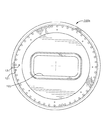
【図3】本発明の好ましい実施の形態に従って構成した閉込本体を示す正面図である。
【図4】図3を4−4線の方向に見た図である。
【図5】図3の5−5線の方向に見た断面図である。
【図6】本発明の好ましい実施の形態に従って構成した閉込本体の第1カバーの正面図である。
【図7】図6のカバーの背面図である。
【図8】図6を8−8線の方向に見た図である。
【図9】図6の9−9線の方向に見た断面図である。
【図10】図6の10−10線の方向に見た断面図である。
【図11】本発明の好ましい実施の形態に従って構成した閉込本体の第2カバーの正面図である。
【図12】図11のカバーの前面図である。
【図13】図11を13−13線の方向に見た図である。
【図14】図11の14−14線の方向に見た断面図である。
【図15】図11の15−15線の方向に見た断面図である。
【図16】閉込本体に取り付けられた磁石の斜視図である。
【図17】第1,第2カバーに取り付けられた磁石の斜視図である。
【図18】本発明の好ましい実施の形態に従って構成した複数の磁気フィルタロッドの多数を含むフィルタロッド組立体の正面図である。
【図19】図18の19−19線の方向に見た図である。
【図20】図19の20−20線の方向に見た、1つのフィルタロッドの断面図である。
【図21】閉込本体に磁石を保持するのに使用するリテーナロッドの図である。
【図22】出口フランジ部の背面図である。
【図23】(a)は、閉込磁界とフィルタ磁界を示すイオンビーム中和器の模式正面図であり、(b)は、その模式側面図である。
【図24】(a)は、閉込磁界を示すイオンビーム中和器の模式側面図であり、(b)は、その模式正面図である。[0001]
BACKGROUND OF THE INVENTION
The present invention relates to an ion beam neutralizer used for processing a workpiece such as a wafer and a neutralization method thereof.
[0002]
[Prior art]
Ion beam implanters are used to treat silicon wafers with ion beams. Such a treatment can be used to dope an N-type or P-type impurity material and to form an inactive layer when manufacturing an integrated circuit.
[0003]
If an ion beam implanter is used to dope the semiconductor, the selected ion species is implanted to produce the desired impurity material. When ions generated from material sources such as antimony, arsenic (As), and phosphorus (P) are implanted, an N-type impurity material wafer is obtained. When a P-type impurity material wafer is required, ion species generated from a material source such as boron (B), gallium (Ga), and indium (In) are implanted.
[0004]
The ion beam implanter includes an ion source for generating positively charged ions from an ionizable material. The generated ions are formed into a beam, accelerated along a predetermined beam path, and headed toward the implantation portion.
[0005]
The ion beam implantation apparatus includes a beam forming / shaping structure portion extending between the ion source and the implantation portion. The beam forming / shaping structure portion defines an elongated internal cavity or internal region through which the ion beam is maintained while passing through the ion beam to the implantation portion. When operating the ion implanter, the interior region must be evacuated in order to reduce the possibility that ions will collide with molecules in the air and thereby escape from the predetermined beam path.
[0006]
Eaton, the assignee of the present invention, sells high current injection devices under the product names NV10, NV-GSD / 200, NV-GSD / 160, NV-GSD / 80. One problem with these prior art implanters is the problem of wafer charging. Since the ion beam is irradiated so as to contact the wafer, the wafer is charged so that positively charged ions strike the wafer surface. This charge is often non-uniform, creating a large electric field on the wafer surface, damaging the wafer and making it unsuitable for use as a semiconductor material.
[0007]
In some prior art implanters, an electron shower device is used to neutralize the space charge of the ion beam. Existing electron shower devices utilize secondary electron emission that occurs when active electrons strike a metal surface. Low energy electrons emitted from the metal surface are either trapped in the ion beam or irradiated to impinge on the wafer surface, thereby directly neutralizing the wafer.
[0008]
The current density of electrons obtained by secondary electron emission from the metal surface is limited by the potential difference between the ion beam and the electron emitting surface. The neutralization device of the existing ion implantation apparatus applies an electric field for carrying electrons from the outer region of the ion beam into the ion beam where the electrons are captured by the ion beam. As electrons are captured by the ion beam, they can move freely along the beam in the direction of the target that cancels the flow of the positive ion beam.
[0009]
The electric field that carries the electrons into the ion beam also deflects the beam ions away from the concentrated beam path. In order for electrons to be captured by the beam, a collision is required between the electrons and the beam plasma particles (neutral and ionized state).
[0010]
If such a collision does not occur, the electrons simply vibrate through the beam and around it with a shocking movement. The rate of collision between ions and electrons is limited by the electron density that determines the probability of collision. In general, the rate of collision between electrons and ions results in incomplete neutralization, and the residual space charge effect of a positively charged ion beam is important.
[0011]
The type of electron flood known as "plasma bridge" partially addresses these limitations. Ion and electron plasma is created in a cavity near the ion beam. Since this cavity is generally separated from the ion beam, a high-density gas that promotes plasma generation can be used in the cavity. The plasma passes through a small opening to allow “leakage” from the cavity. A high current flows from the opening toward the ion beam plasma. This high current flows from the cavity toward the beam, and the charging is almost neutralized by the plasma bridge.
[0012]
Even when using a plasma bridge, an electric field is required along the bridge to maintain the current. Since the plasma bridge extends from the opening of the cavity where the plasma is generated, the diffusion of electrons is replaced by the impact action as the primary mode of electron transport.
[0013]
To the extent that existing ion beam neutralizers use electric fields from the electron generation region to the region where electrons are injected into the ion beam, these electric fields also increase the kinetic energy of the electrons, thereby reducing the vibration of the electrons. Promotes and avoids trapping in the ion beam.
[0014]
[Problems to be solved by the invention]
In view of such circumstances, an object of the present invention is to provide an ion beam neutralizer of an ion implantation apparatus for treating one or more workpieces with positively charged ions and a neutralization method thereof.
[0015]
[Means for Solving the Problems]
In order to achieve the above object, the present invention has the structure described in each claim. Specifically, according to a preferred embodiment of the present invention, an ion implanter includes an ion source, a beam forming structure (electrode), an ion beam neutralizer, and an ion implantation station.
[0016]
The ion source emits positive ions and is formed into an ion beam by a beam forming electrode. The ion implantation station is positioned such that ions from the ion beam are captured by one or more workpieces as the ions enter the ion implantation station.
[0017]
The ion beam neutralizer is disposed upstream of the ion implantation station along the ion beam path. In accordance with the present invention, the ion beam neutralizer comprises a confinement assembly that includes a confinement body, an inlet cover, and an outlet cover that are surrounded along the ion beam path. Both covers of the confinement assembly form an inlet plate and an outlet plate to allow the ion beam to pass through the neutralization region before ions are implanted into one or more workpieces at the ion implantation station. .
[0018]
A plasma source is positioned in the confined body for supplying electrons into the neutralization region. The confinement body further supports a group of arrayed magnets that generate a magnetic field in the neutralization region, which confine the electrons emitted from the electron source, thereby concentrating the electrons more in the neutralization region. Like that.
[0019]
Within the neutralization region, the electric field is quite small and electrons initially migrate by diffusion from a high density region to a low density region. Free electrons are generated in the ion beam itself or diffuse into the beam from surrounding areas where no electric field acts. When electrons are captured by the beam, a high electron flow flows along the ion beam toward one or more workpieces at the ion implantation station, against the electric field on the ion beam trajectory.
[0020]
The ion beam neutralizer must have a plasma density much higher than the plasma density of the ion beam because of the diffusion process to dominate the electron motion. Also, the ion beam neutralizer must be operated at a low gas pressure to avoid excessive attenuation of the ion beam.
[0021]
According to another aspect of the invention, an ion beam neutralizer includes a filter rod assembly having a plurality of magnet filter rods supported in a confined body and having a plurality of axially extending metal filter rods. I have. The filter rod extends along the ion beam path and forms a magnetic field that delimits the ion beam.
[0022]
The filter rod assembly confines more active electrons from the existing ion beam and forces low energy electrons along the ion beam plasma. This filter rod assembly has several advantages in an ion beam neutralizer. That is, the filter rod limits the maximum possible negative charge of the workpiece that is one or more targets. Furthermore, the filter rod assembly minimizes heating of the ion beam plasma near the upstream portion of the ion beam neutralizer.
[0023]
The movement of the electron flood is determined by measuring the voltage at the center of the ion beam upstream from the insulated target. The low voltage corresponds to a low residual space charge in the ion beam due to incomplete neutralization. In the ion beam neutralizer disclosed in the preferred embodiment, when a similar ion beam is used, other conventional electron floods have a beam voltage of about 15 to 60 volts, compared to about 5 to 7 volts. The beam voltage was found to be
[0024]
DETAILED DESCRIPTION OF THE INVENTION
Referring to FIG. 1, an
[0025]
An electronic controller (not shown) monitors and controls the ion dose received by the wafer (not shown) in the implantation chamber 17 at the implantation station 16.
[0026]
The ions in the ion beam travel along a predetermined preferred beam path, but tend to diverge as the beam travels the distance between the
[0027]
The ion source material can include gas or vaporized ionizable material. After the solid ion source material is placed in the vaporizer, it is injected into the
[0028]
If an n-type semiconductor wafer material is desired, boron, gallium, or indium is used. Gallium and indium are solid ion source materials, while boron is typically injected into the
[0029]
When producing a p-type semiconductor wafer material, antimony, arsenic, or phosphorus is selected as the solid ion source material. Energy is applied to the ion source material to generate positively charged ions in the
[0030]
The
[0031]
The
[0032]
Ions in the
[0033]
The pair of
[0034]
The ions that make up the
[0035]
The
[0036]
The magnetic field generated by the
[0037]
A
[0038]
The
[0039]
As described above, since the strength and direction of the magnetic field of the
[0040]
Unfavorable ionic species having an atomic mass greater or smaller than the preferred atomic mass are strongly deflected and impinge on the slit formed by the
[0041]
An adjustable resolving slit 41 and a Faraday flag 42 are disposed between the resolving
[0042]
The beamformer includes a
[0043]
Ions extracted from the
[0044]
The downstream end of the
[0045]
The
2 to 23 show an optimal embodiment of the
[0046]
The
[0047]
The
[0048]
The
[0049]
Referring to FIG. 3, the metal (typically aluminum)
[0050]
As conceptually shown in FIG. 23 a, the
[0051]
At both ends of the holding
[0052]
4 and 5, the
[0053]
According to a preferred embodiment, as conceptually shown in FIG. 23b, the electronic excitation source comprises a
[0054]
Another embodiment is conceptually shown in FIGS. 24a and 24b, where the
[0055]
The
[0056]
The
[0057]
As shown in FIG. 1, the outer surface of the confining
[0058]
6 to 10 show a
[0059]
As shown in FIG. 6, depending on the placement of the
[0060]
[0061]
As shown in FIG. 2, the magnetic confinement plate (inlet plate) 111 is in the
[0062]
Each of the
[0063]
In addition, the
[0064]
The
[0065]
The
[0066]
As shown in FIG. 20, the
[0067]
The
[0068]
This phenomenon is Je. tea. This is explained in detail in a paper by AJTHolmes, "Electron Flow in Transverse Magnetic Field in Magnetic Arc Discharge (Rev. Sci. Instrum. 53 (10), October 1982, P1517)". Is included.
[0069]
The filter rod limits one or more target workpieces from being negatively charged. Further, the
[0070]
Referring to FIG. 22, the
[0071]
From the description of the preferred embodiments of the present invention, those skilled in the art can make improvements, changes and modifications of the present invention. All such improvements, changes and modifications are encompassed within the scope of the appended claims.
[Brief description of the drawings]
FIG. 1 is a schematic view of an ion implantation apparatus for treating a workpiece such as a silicon wafer mounted on a rotating support with an ion beam.
FIG. 2 is an exploded perspective view of an ion beam neutralizer configured in accordance with a preferred embodiment of the present invention.
FIG. 3 is a front view of a confining body constructed in accordance with a preferred embodiment of the present invention.
FIG. 4 is a diagram when FIG. 3 is viewed in the direction of line 4-4.
5 is a cross-sectional view seen in the direction of line 5-5 in FIG. 3;
FIG. 6 is a front view of a first cover of a closing body configured according to a preferred embodiment of the present invention.
7 is a rear view of the cover of FIG. 6. FIG.
FIG. 8 is a diagram when FIG. 6 is viewed in the direction of line 8-8.
9 is a cross-sectional view seen in the direction of line 9-9 in FIG. 6;
10 is a cross-sectional view seen in the direction of line 10-10 in FIG. 6;
FIG. 11 is a front view of a second cover of the closing body configured according to a preferred embodiment of the present invention.
12 is a front view of the cover of FIG. 11. FIG.
FIG. 13 is a diagram when FIG. 11 is viewed in the direction of line 13-13.
14 is a cross-sectional view taken along the line 14-14 in FIG.
15 is a cross-sectional view taken along the line 15-15 in FIG.
FIG. 16 is a perspective view of a magnet attached to a closed main body.
FIG. 17 is a perspective view of a magnet attached to the first and second covers.
FIG. 18 is a front view of a filter rod assembly including a number of magnetic filter rods constructed in accordance with a preferred embodiment of the present invention.
19 is a view seen in the direction of line 19-19 in FIG.
20 is a cross-sectional view of one filter rod as seen in the direction of line 20-20 in FIG.
FIG. 21 is a view of a retainer rod used to hold a magnet in a closed body.
22 is a rear view of the outlet flange portion. FIG.
FIG. 23 (a) is closed Included It is a model front view of the ion beam neutralizer which shows a magnetic field and a filter magnetic field, (b) is the model side view.
FIG. 24 (a) is closed Included It is a model side view of the ion beam neutralizer which shows a magnetic field, (b) is the model front view.
Claims (18)
前記注入ステーションで1つ以上の加工物にイオンを衝突させる前にイオンビーム(14)が中和領域を通過できるように、入口及び出口を有する閉込本体(120)によってイオンビームの境界を定め、
前記イオンビームが前記閉込本体(120)内を通過するとき、電子源から中和領域内に電子を供給し、
電子源(126,199)からの電子を、前記閉込本体の側壁、入口、及び出口に対して離設された複数の磁石 (124,164) により前記中和領域内に形成される閉込磁界によって前記閉込本体(120)内に閉じ込めるとともに、軸方向に伸びる複数の金属製のフィルタロッド (208) を含み、該フィルタロッドのそれぞれは細長いフィルタ磁石 (224) を収容し、複数のフィルタロッドがイオンビーム移動路の方向にほぼ平行に向けられて前記電子源から半径方向内方に離設されるように前記中和領域内に配置されるフィルタロッド組立体 (200) により形成されるフィルタ磁界によって、高エネルギ電子を閉じ込め、低エネルギー電子をドリフトさせる、各ステップを有することを特徴とするイオンビームの中和方法。An ion source (12) for emitting positively charged ions, a structure for forming an ion beam (14) from the positively charged ions, and one or more workpieces are positioned and the ions in the ion beam are positioned at that location. in an ion implanter having an ion implantation station (16) for impinging at along earthenware pots on the upstream position to the ion beam path from the processing position of the workpiece, the neutralization of the ion beam that emits electrons into the ion beam A method,
The ion beam is delimited by a confinement body (120) having an inlet and an outlet so that the ion beam (14) can pass through the neutralization region before impinging ions on one or more workpieces at the implantation station. ,
When the ion beam passes through the confinement body (120), the electronic subjected fed into the neutralization region from the electron source,
Electrons from the electron source (126, 199) are closed by a confining magnetic field formed in the neutralization region by a plurality of magnets (124, 164) spaced from the side wall, the inlet, and the outlet of the confining body. A plurality of metallic filter rods (208) confined within the recessed body (120) and extending in the axial direction, each of the filter rods containing an elongated filter magnet (224) , wherein the plurality of filter rods are ion beams By a filter magnetic field formed by a filter rod assembly (200) positioned in the neutralization region so as to be substantially parallel to the direction of the travel path and spaced radially inward from the electron source , A method for neutralizing an ion beam, comprising: steps for confining high energy electrons and drifting low energy electrons .
Applications Claiming Priority (2)
| Application Number | Priority Date | Filing Date | Title |
|---|---|---|---|
| US691467 | 1996-08-02 | ||
| US08/691,467 US5703375A (en) | 1996-08-02 | 1996-08-02 | Method and apparatus for ion beam neutralization |
Publications (2)
| Publication Number | Publication Date |
|---|---|
| JPH1083783A JPH1083783A (en) | 1998-03-31 |
| JP4239116B2 true JP4239116B2 (en) | 2009-03-18 |
Family
ID=24776645
Family Applications (1)
| Application Number | Title | Priority Date | Filing Date |
|---|---|---|---|
| JP20895197A Expired - Lifetime JP4239116B2 (en) | 1996-08-02 | 1997-08-04 | Ion beam neutralizer and neutralization method thereof |
Country Status (7)
| Country | Link |
|---|---|
| US (1) | US5703375A (en) |
| EP (1) | EP0822571A3 (en) |
| JP (1) | JP4239116B2 (en) |
| KR (1) | KR100354992B1 (en) |
| CN (1) | CN1132227C (en) |
| CA (1) | CA2210383A1 (en) |
| TW (1) | TW350974B (en) |
Cited By (3)
| Publication number | Priority date | Publication date | Assignee | Title |
|---|---|---|---|---|
| US10048594B2 (en) | 2016-02-19 | 2018-08-14 | Tokyo Electron Limited | Photo-sensitized chemically amplified resist (PS-CAR) model calibration |
| US10096528B2 (en) | 2016-05-13 | 2018-10-09 | Tokyo Electron Limited | Critical dimension control by use of a photo agent |
| US10429745B2 (en) | 2016-02-19 | 2019-10-01 | Osaka University | Photo-sensitized chemically amplified resist (PS-CAR) simulation |
Families Citing this family (39)
| Publication number | Priority date | Publication date | Assignee | Title |
|---|---|---|---|---|
| US6271529B1 (en) * | 1997-12-01 | 2001-08-07 | Ebara Corporation | Ion implantation with charge neutralization |
| US6184532B1 (en) | 1997-12-01 | 2001-02-06 | Ebara Corporation | Ion source |
| US5959305A (en) * | 1998-06-19 | 1999-09-28 | Eaton Corporation | Method and apparatus for monitoring charge neutralization operation |
| US6094012A (en) * | 1998-11-06 | 2000-07-25 | The Regents Of The University Of California | Low energy spread ion source with a coaxial magnetic filter |
| US6420713B1 (en) * | 1999-04-28 | 2002-07-16 | Nikon Corporation | Image position and lens field control in electron beam systems |
| US6414329B1 (en) | 2000-07-25 | 2002-07-02 | Axcelis Technologies, Inc. | Method and system for microwave excitation of plasma in an ion beam guide |
| US6541781B1 (en) | 2000-07-25 | 2003-04-01 | Axcelis Technologies, Inc. | Waveguide for microwave excitation of plasma in an ion beam guide |
| US6703628B2 (en) | 2000-07-25 | 2004-03-09 | Axceliss Technologies, Inc | Method and system for ion beam containment in an ion beam guide |
| US6476399B1 (en) * | 2000-09-01 | 2002-11-05 | Axcelis Technologies, Inc. | System and method for removing contaminant particles relative to an ion beam |
| DE10130464B4 (en) * | 2001-06-23 | 2010-09-16 | Thales Electron Devices Gmbh | Plasma accelerator configuration |
| US6635890B2 (en) | 2001-08-23 | 2003-10-21 | Axcelis Technologies, Inc. | Slit double gap buncher and method for improved ion bunching in an ion implantation system |
| US6583429B2 (en) | 2001-08-23 | 2003-06-24 | Axcelis Technologies, Inc. | Method and apparatus for improved ion bunching in an ion implantation system |
| JP3840108B2 (en) * | 2001-12-27 | 2006-11-01 | 株式会社 Sen−Shi・アクセリス カンパニー | Ion beam processing method and processing apparatus |
| JP3680274B2 (en) * | 2002-03-27 | 2005-08-10 | 住友イートンノバ株式会社 | Ion beam charge neutralization apparatus and method |
| US6956223B2 (en) * | 2002-04-10 | 2005-10-18 | Applied Materials, Inc. | Multi-directional scanning of movable member and ion beam monitoring arrangement therefor |
| CA2500845C (en) | 2002-10-03 | 2012-07-31 | Virginia Tech Intellectual Properties, Inc. | Magnetic targeting device |
| US20040227106A1 (en) * | 2003-05-13 | 2004-11-18 | Halling Alfred M. | System and methods for ion beam containment using localized electrostatic fields in an ion beam passageway |
| US6891174B2 (en) * | 2003-07-31 | 2005-05-10 | Axcelis Technologies, Inc. | Method and system for ion beam containment using photoelectrons in an ion beam guide |
| FR2861947B1 (en) * | 2003-11-04 | 2007-11-09 | Commissariat Energie Atomique | DEVICE FOR CONTROLLING THE ELECTRON TEMPERATURE IN AN NCE PLASMA |
| US6956225B1 (en) * | 2004-04-01 | 2005-10-18 | Axcelis Technologies, Inc. | Method and apparatus for selective pre-dispersion of extracted ion beams in ion implantation systems |
| EP1609882A1 (en) * | 2004-06-24 | 2005-12-28 | METAPLAS IONON Oberflächenveredelungstechnik GmbH | Coating device and method by cathodic sputtering |
| KR100553716B1 (en) * | 2004-08-02 | 2006-02-24 | 삼성전자주식회사 | Ion Source Part of Ion Implantation Facility |
| US7459692B2 (en) * | 2004-11-19 | 2008-12-02 | Varian Semiconductor Equipment Associates, Inc. | Electron confinement inside magnet of ion implanter |
| US7402816B2 (en) * | 2004-11-19 | 2008-07-22 | Varian Semiconductor Equipment Associates, Inc. | Electron injection in ion implanter magnets |
| JP4514157B2 (en) * | 2006-06-12 | 2010-07-28 | 国立大学法人京都大学 | Ion beam irradiation apparatus and semiconductor device manufacturing method |
| US7655922B2 (en) * | 2006-12-07 | 2010-02-02 | Varian Semiconductor Equipment Associates, Inc. | Techniques for confining electrons in an ion implanter |
| US7723699B2 (en) * | 2007-06-26 | 2010-05-25 | Varian Semiconductor Equipment Associates, Inc. | Cathode having electron production and focusing grooves, ion source and related method |
| US7723707B2 (en) * | 2007-07-23 | 2010-05-25 | Varian Semiconductor Equipment Associates, Inc. | Techniques for plasma injection |
| US7692139B2 (en) * | 2007-10-15 | 2010-04-06 | Varian Semiconductor Equipment Associates, Inc. | Techniques for commensurate cusp-field for effective ion beam neutralization |
| US7800083B2 (en) * | 2007-11-06 | 2010-09-21 | Axcelis Technologies, Inc. | Plasma electron flood for ion beam implanter |
| WO2010028046A1 (en) * | 2008-09-02 | 2010-03-11 | Virginia Tech Intellectual Properties | Intramedullary nail targeting device |
| WO2012051512A1 (en) | 2010-10-14 | 2012-04-19 | Virginia Tech Intellectual Properties, Inc. | Intramedullary nail targeting device |
| JP2013089409A (en) * | 2011-10-17 | 2013-05-13 | Sen Corp | Ion implantation device and ion implantation method |
| TWI508127B (en) * | 2012-11-13 | 2015-11-11 | E G Electro Graph Inc | Magnetic field reduction apparatus and magnetic plasma flood system for ion beam processing |
| CN105470084B (en) * | 2014-07-31 | 2017-12-26 | 上海凯世通半导体股份有限公司 | Electronics supply system |
| CN108732610B (en) * | 2017-04-25 | 2020-12-25 | 北京中科信电子装备有限公司 | Novel Faraday device for measuring ion beam |
| CN107293347B (en) * | 2017-07-10 | 2023-09-29 | 中国原子能科学研究院 | Beam on-line charge polarity conversion device |
| CN109087840B (en) * | 2018-09-27 | 2023-11-07 | 中山市博顿光电科技有限公司 | Water-cooled radio frequency neutralizer |
| CN113808907B (en) * | 2021-09-18 | 2024-06-18 | 中国科学院近代物理研究所 | Magnet structure for generating and extracting negative oxygen ion beam |
Family Cites Families (13)
| Publication number | Priority date | Publication date | Assignee | Title |
|---|---|---|---|---|
| US4361762A (en) * | 1980-07-30 | 1982-11-30 | Rca Corporation | Apparatus and method for neutralizing the beam in an ion implanter |
| US4786814A (en) * | 1983-09-16 | 1988-11-22 | General Electric Company | Method of reducing electrostatic charge on ion-implanted devices |
| JPS62103951A (en) * | 1985-10-29 | 1987-05-14 | Toshiba Corp | Ion implanting apparatus |
| JPH0766763B2 (en) * | 1987-03-09 | 1995-07-19 | 日本電信電話株式会社 | Ion neutralizer |
| JPS63221539A (en) * | 1987-03-10 | 1988-09-14 | Mitsubishi Electric Corp | Ion beam neutralizing device |
| JPS63274051A (en) * | 1987-04-30 | 1988-11-11 | Sumitomo Electric Ind Ltd | Ion beam neutralizer |
| JPS6438959A (en) * | 1987-08-04 | 1989-02-09 | Mitsubishi Electric Corp | Ion beam neutralization device |
| US4804837A (en) * | 1988-01-11 | 1989-02-14 | Eaton Corporation | Ion implantation surface charge control method and apparatus |
| JPH03216945A (en) * | 1990-01-23 | 1991-09-24 | Mitsubishi Electric Corp | Ion implanter |
| JPH04308637A (en) * | 1991-04-04 | 1992-10-30 | Matsushita Electron Corp | Ion beam neutralizing device |
| US5164599A (en) * | 1991-07-19 | 1992-11-17 | Eaton Corporation | Ion beam neutralization means generating diffuse secondary emission electron shower |
| JPH0689690A (en) * | 1992-09-07 | 1994-03-29 | Nec Yamagata Ltd | Ion beam neutralizing device for ion implanting device |
| US5531420A (en) * | 1994-07-01 | 1996-07-02 | Eaton Corporation | Ion beam electron neutralizer |
-
1996
- 1996-08-02 US US08/691,467 patent/US5703375A/en not_active Expired - Lifetime
-
1997
- 1997-07-22 CA CA002210383A patent/CA2210383A1/en not_active Abandoned
- 1997-07-22 TW TW086110393A patent/TW350974B/en not_active IP Right Cessation
- 1997-07-24 EP EP97305547A patent/EP0822571A3/en not_active Withdrawn
- 1997-08-02 KR KR1019970037130A patent/KR100354992B1/en not_active IP Right Cessation
- 1997-08-02 CN CN97118579A patent/CN1132227C/en not_active Expired - Fee Related
- 1997-08-04 JP JP20895197A patent/JP4239116B2/en not_active Expired - Lifetime
Cited By (3)
| Publication number | Priority date | Publication date | Assignee | Title |
|---|---|---|---|---|
| US10048594B2 (en) | 2016-02-19 | 2018-08-14 | Tokyo Electron Limited | Photo-sensitized chemically amplified resist (PS-CAR) model calibration |
| US10429745B2 (en) | 2016-02-19 | 2019-10-01 | Osaka University | Photo-sensitized chemically amplified resist (PS-CAR) simulation |
| US10096528B2 (en) | 2016-05-13 | 2018-10-09 | Tokyo Electron Limited | Critical dimension control by use of a photo agent |
Also Published As
| Publication number | Publication date |
|---|---|
| EP0822571A2 (en) | 1998-02-04 |
| CN1179003A (en) | 1998-04-15 |
| CN1132227C (en) | 2003-12-24 |
| US5703375A (en) | 1997-12-30 |
| KR100354992B1 (en) | 2002-12-26 |
| EP0822571A3 (en) | 2001-10-04 |
| CA2210383A1 (en) | 1998-02-02 |
| KR19980018332A (en) | 1998-06-05 |
| JPH1083783A (en) | 1998-03-31 |
| TW350974B (en) | 1999-01-21 |
Similar Documents
| Publication | Publication Date | Title |
|---|---|---|
| JP4239116B2 (en) | Ion beam neutralizer and neutralization method thereof | |
| KR101464484B1 (en) | Plasma electron flood for ion beam implanter | |
| US5399871A (en) | Plasma flood system for the reduction of charging of wafers during ion implantation | |
| KR100318873B1 (en) | Method and apparatus for ion formation in ion implanter | |
| JP4470127B2 (en) | Ion implantation apparatus and ion implantation method | |
| JP2961326B2 (en) | Ion implanter | |
| EP0324247A2 (en) | Ion implantation surface charge control method and apparatus | |
| CN1922707B (en) | Modulating ion beam current | |
| US6723998B2 (en) | Faraday system for ion implanters | |
| US4914292A (en) | Ion implanting apparatus | |
| KR100904313B1 (en) | Contaminant removal system and method for ion beam | |
| US5531420A (en) | Ion beam electron neutralizer | |
| GB2326971A (en) | Electron flood apparatus for neutralising charge build up on a substrate during ion implantation | |
| JP2006156142A (en) | Wafer electrification suppressing device and ion implantation device provided with the same | |
| KR102334205B1 (en) | Pinched plasma bridge flood gun for substrate charge neutralization | |
| JP3264988B2 (en) | Ion implanter | |
| JPH04123755A (en) | Ion implantation apparatus |
Legal Events
| Date | Code | Title | Description |
|---|---|---|---|
| A621 | Written request for application examination |
Free format text: JAPANESE INTERMEDIATE CODE: A621 Effective date: 20040518 |
|
| A131 | Notification of reasons for refusal |
Free format text: JAPANESE INTERMEDIATE CODE: A131 Effective date: 20080109 |
|
| A601 | Written request for extension of time |
Free format text: JAPANESE INTERMEDIATE CODE: A601 Effective date: 20080408 |
|
| A602 | Written permission of extension of time |
Free format text: JAPANESE INTERMEDIATE CODE: A602 Effective date: 20080411 |
|
| A521 | Request for written amendment filed |
Free format text: JAPANESE INTERMEDIATE CODE: A523 Effective date: 20080501 |
|
| A131 | Notification of reasons for refusal |
Free format text: JAPANESE INTERMEDIATE CODE: A131 Effective date: 20080528 |
|
| A601 | Written request for extension of time |
Free format text: JAPANESE INTERMEDIATE CODE: A601 Effective date: 20080828 |
|
| A602 | Written permission of extension of time |
Free format text: JAPANESE INTERMEDIATE CODE: A602 Effective date: 20080902 |
|
| A601 | Written request for extension of time |
Free format text: JAPANESE INTERMEDIATE CODE: A601 Effective date: 20080929 |
|
| A602 | Written permission of extension of time |
Free format text: JAPANESE INTERMEDIATE CODE: A602 Effective date: 20081002 |
|
| A521 | Request for written amendment filed |
Free format text: JAPANESE INTERMEDIATE CODE: A523 Effective date: 20081027 |
|
| TRDD | Decision of grant or rejection written | ||
| A01 | Written decision to grant a patent or to grant a registration (utility model) |
Free format text: JAPANESE INTERMEDIATE CODE: A01 Effective date: 20081126 |
|
| A01 | Written decision to grant a patent or to grant a registration (utility model) |
Free format text: JAPANESE INTERMEDIATE CODE: A01 |
|
| A61 | First payment of annual fees (during grant procedure) |
Free format text: JAPANESE INTERMEDIATE CODE: A61 Effective date: 20081211 |
|
| FPAY | Renewal fee payment (event date is renewal date of database) |
Free format text: PAYMENT UNTIL: 20120109 Year of fee payment: 3 |
|
| R150 | Certificate of patent or registration of utility model |
Free format text: JAPANESE INTERMEDIATE CODE: R150 |
|
| FPAY | Renewal fee payment (event date is renewal date of database) |
Free format text: PAYMENT UNTIL: 20130109 Year of fee payment: 4 |
|
| R250 | Receipt of annual fees |
Free format text: JAPANESE INTERMEDIATE CODE: R250 |
|
| R250 | Receipt of annual fees |
Free format text: JAPANESE INTERMEDIATE CODE: R250 |
|
| R250 | Receipt of annual fees |
Free format text: JAPANESE INTERMEDIATE CODE: R250 |
|
| R250 | Receipt of annual fees |
Free format text: JAPANESE INTERMEDIATE CODE: R250 |
|
| EXPY | Cancellation because of completion of term |