JP4237862B2 - Screws used as fasteners for fiber materials such as wood - Google Patents
Screws used as fasteners for fiber materials such as wood Download PDFInfo
- Publication number
- JP4237862B2 JP4237862B2 JP09769299A JP9769299A JP4237862B2 JP 4237862 B2 JP4237862 B2 JP 4237862B2 JP 09769299 A JP09769299 A JP 09769299A JP 9769299 A JP9769299 A JP 9769299A JP 4237862 B2 JP4237862 B2 JP 4237862B2
- Authority
- JP
- Japan
- Prior art keywords
- screw
- notch
- edge
- tooth
- screw according
- Prior art date
- Legal status (The legal status is an assumption and is not a legal conclusion. Google has not performed a legal analysis and makes no representation as to the accuracy of the status listed.)
- Expired - Lifetime
Links
Images


Classifications
-
- F—MECHANICAL ENGINEERING; LIGHTING; HEATING; WEAPONS; BLASTING
- F16—ENGINEERING ELEMENTS AND UNITS; GENERAL MEASURES FOR PRODUCING AND MAINTAINING EFFECTIVE FUNCTIONING OF MACHINES OR INSTALLATIONS; THERMAL INSULATION IN GENERAL
- F16B—DEVICES FOR FASTENING OR SECURING CONSTRUCTIONAL ELEMENTS OR MACHINE PARTS TOGETHER, e.g. NAILS, BOLTS, CIRCLIPS, CLAMPS, CLIPS OR WEDGES; JOINTS OR JOINTING
- F16B25/00—Screws that cut thread in the body into which they are screwed, e.g. wood screws
- F16B25/001—Screws that cut thread in the body into which they are screwed, e.g. wood screws characterised by the material of the body into which the screw is screwed
- F16B25/0015—Screws that cut thread in the body into which they are screwed, e.g. wood screws characterised by the material of the body into which the screw is screwed the material being a soft organic material, e.g. wood or plastic
-
- F—MECHANICAL ENGINEERING; LIGHTING; HEATING; WEAPONS; BLASTING
- F16—ENGINEERING ELEMENTS AND UNITS; GENERAL MEASURES FOR PRODUCING AND MAINTAINING EFFECTIVE FUNCTIONING OF MACHINES OR INSTALLATIONS; THERMAL INSULATION IN GENERAL
- F16B—DEVICES FOR FASTENING OR SECURING CONSTRUCTIONAL ELEMENTS OR MACHINE PARTS TOGETHER, e.g. NAILS, BOLTS, CIRCLIPS, CLAMPS, CLIPS OR WEDGES; JOINTS OR JOINTING
- F16B25/00—Screws that cut thread in the body into which they are screwed, e.g. wood screws
- F16B25/0036—Screws that cut thread in the body into which they are screwed, e.g. wood screws characterised by geometric details of the screw
- F16B25/0042—Screws that cut thread in the body into which they are screwed, e.g. wood screws characterised by geometric details of the screw characterised by the geometry of the thread, the thread being a ridge wrapped around the shaft of the screw
- F16B25/0052—Screws that cut thread in the body into which they are screwed, e.g. wood screws characterised by geometric details of the screw characterised by the geometry of the thread, the thread being a ridge wrapped around the shaft of the screw the ridge having indentations, notches or the like in order to improve the cutting behaviour
-
- F—MECHANICAL ENGINEERING; LIGHTING; HEATING; WEAPONS; BLASTING
- F16—ENGINEERING ELEMENTS AND UNITS; GENERAL MEASURES FOR PRODUCING AND MAINTAINING EFFECTIVE FUNCTIONING OF MACHINES OR INSTALLATIONS; THERMAL INSULATION IN GENERAL
- F16B—DEVICES FOR FASTENING OR SECURING CONSTRUCTIONAL ELEMENTS OR MACHINE PARTS TOGETHER, e.g. NAILS, BOLTS, CIRCLIPS, CLAMPS, CLIPS OR WEDGES; JOINTS OR JOINTING
- F16B35/00—Screw-bolts; Stay-bolts; Screw-threaded studs; Screws; Set screws
- F16B35/04—Screw-bolts; Stay-bolts; Screw-threaded studs; Screws; Set screws with specially-shaped head or shaft in order to fix the bolt on or in an object
- F16B35/041—Specially-shaped shafts
- F16B35/048—Specially-shaped necks
Landscapes
- Engineering & Computer Science (AREA)
- General Engineering & Computer Science (AREA)
- Mechanical Engineering (AREA)
- Geometry (AREA)
- Dispersion Chemistry (AREA)
- Chemical & Material Sciences (AREA)
- Physics & Mathematics (AREA)
- Life Sciences & Earth Sciences (AREA)
- Wood Science & Technology (AREA)
- Connection Of Plates (AREA)
- Dowels (AREA)
- Hand Tools For Fitting Together And Separating, Or Other Hand Tools (AREA)
- Food-Manufacturing Devices (AREA)
- Golf Clubs (AREA)
- Artificial Filaments (AREA)
- Joining Of Building Structures In Genera (AREA)
- Dry Formation Of Fiberboard And The Like (AREA)
Abstract
Description
【0001】
【発明の属する技術分野】
本発明は木ネジ、特に木材などの繊維質材を固定締結するために使用するセルフタッピンネジに関する。
【0002】
【従来の技術】
従来の木ネジには滑らかな連続するネジ山が配設されており、繊維質の被締結物の繊維密度が薄い場合や下穴が用意されている場合は、前述のようなネジ山のネジで充分締結可能である。
しかし木材、繊維状ボードなどの比較的繊維密度が濃い被締結物を締結する場合、または下穴が用意されていない場合は、従来のネジを完全にねじ込むためには高トルクを必要とする。特に電動スクリュードライバーを使用してネジの高トルクを求めると、ネジを破壊しかねず、被締結物が破損する場合がある。
【0003】
そこで繊維質の被締結物に使用するネジは、破損の可能性を回避し少なくとも減少しつつ、引抜けや緩みに対する抵抗度を高めることが好ましい。
そのため、国際公表公報第WO98/44268号には、堅い木材へのネジ込みを容易にするための木ネジの構造が開示されており、このネジのネジ山には実質的にはネジ先端から始まる多数のV字型切り欠き部分が設けられている。V字型の切り欠き部分を備えた前記ネジ山はネジの軸部全長に亘って延びている。
【0004】
一方、英国特許第1120991号に記載される木ネジには、軸部のネジ部ほぼ全長に亘ってネジ山を螺旋状に延びる溝が設けられており、ネジ山は放射状外方に突出する多数の突起部状に形成されている。
【0005】
前記の各々の従来型木ネジは、実質的にはネジ全体のトルク強度が弱く、電動スクリュードライバーを使用すると特に破損しやすい上、各切り欠き部分のカット端部により発生する削り屑を排出する空隙が不足している。さらにネジ先端にも切り欠き部分が設けられているため、被締結物に対するネジのねじ込みの案内を妨害している。
【0006】
【発明が解決しようとする課題】
そこで本発明はこのような実情に鑑みなされたものであり、その目的は、ネジの最良トルク強度を維持しながら被締結物にネジ込む力を節約でき、止めたネジが自ら緩むということを回避し得うる、木材などの繊維質材のネジ止めが容易に行えるネジを提供することにある。
【0007】
本発明のネジには、ネジ部全長の所定部分にのみ半径方向内方に向かって幅が狭くなっている切り欠き部が設けられている。本発明の別の特徴によれば、一対の短い間隔をおいて配されたV字型切り欠き部分からなるW型の切り欠き部が所定部分のネジ山の一螺旋につき3箇所に形成される。各々切り欠き部分のないネジ部の第1端部もしくは先端と、第2端部もしくは頭部端部との中間に前記所定破断ネジ部を軸状に配設している。
【0008】
【課題を解決するための手段】
前記の目的は、請求項1の特徴部分に記載した事項、すなわち、軸部が、先端部を形成する第1端部と、頭部と奏合する第2端部と、軸部全長の少なくとも一部に螺旋状に設けられたネジ山を有するネジ部とからなり、前記ネジ部全長の所定部分には各ネジ山頂点で互いに一定の間隔をおいて配され且つ半径方向内方に向いた複数の切り欠き部が設けられ、前記ネジ部の所定部分は前記第1端部から軸方向に間隔をおいて位置し、前記切り欠き部がこの間隔部分のネジ山に設けられていないことで達成される。
請求項2に示すように、前記各ネジ山に設けられた複数の切り欠き部はそれぞれW字状に形成され、これにより各切り欠き部は、2つの切り欠き部分とこれらの間に位置する歯状部分とから構成されることが好ましい。
請求項3に示すように、前記切り欠き部を有する所定部分はネジ部全体の中間部分に位置することが好ましい。
請求項4〜5に示すように、前記軸部の全長は少なくとも約30mmであり、前記第1端部には切り欠き部が設けられていない約2螺旋のネジ山をし、前記所定部分と第2端部の間には、切り欠き部が設けられていない複数のネジ山が設けられることが好ましい。
請求項6に示すように、前記所定部分には一螺旋につき約3箇所に半径方向内方に向かって幅が狭くなっている切り欠き部が設けられていることが好ましい。
請求項7に示すように、前記切り欠き部の各ネジ山頂点周囲上の各幅を合計すると一螺旋全周の約1/3以下であることが好ましい。
請求項8に示すように、前記軸部の全長は少なくとも約30mmであり、前記切り欠き部は、被締結物のネジ止め回転方向に向かって、前方縁部と後方縁部とをそれぞれ含む前方切欠き部分と後方切欠き部分とから構成され、前記前方切欠き部分の後方縁部は前記中央歯のカット縁部を形成し、前記後方切欠き部分の前方縁部は前記中央歯の後縁部を形成することによって前記歯の前後に空隙が形成されていることが好ましい。
請求項9に示すように、各切欠き部分はその半径方向内方に向いた部分が90度の角度を形成する三角形状であることが好ましい。
請求項10に示すように、前記歯の形状はほぼ台形であることが好ましい。
請求項11並びに13に示すように、前記前方切欠き部分の前方縁部と前記後方切欠き部分の後方縁部は各々ネジ軸部の中心と同心の仮想の第二円の円周との接線上に位置し、歯のカット縁部は軸部中心と同心の仮想第一円の円周との接線上に位置し、前記切欠き部分はその半径方向内方に向いた部分が鋭角を形成する三角形形状をなすことが好ましい。
請求項12並びに14に示すように、第一円の直径がゼロの場合、歯のカット縁部は軸部の半径方向に延びていることが好ましい。
請求項15〜17に示すように、前記軸部の全長が約30mmから約140mmである場合、前記所定破断ネジ部の螺旋数は約3であり、前記軸部の全長が約150mmから約240mmである場合、前記所定破断ネジ部の螺旋数は約4螺旋であり、さらに前記軸部の全長が約250mmから約400mmである場合、前記所定破断ネジ部の螺旋数は約5螺旋であることが好ましい。
【0009】
【発明の実施の態様】
以下に本発明の一実施の形態を添付図面に基づいて説明する。
なお、後述する本発明の別の各実施態様においては、同等部材に関しては同様の符号を付して説明する。
図1は本発明による木ネジの一実施態様を示す側面図であり、図2はネジ部の一螺旋を平面にした、本発明の一実施態様によるネジ山の切り欠き部とその谷の配置を示す図である。図1において、ネジは円筒状軸部10と、ネジ先(テーパ部)11を形成する円筒状軸部10の第1端部と、これに対して頭部端部12と奏合した円筒状軸部10の第2端部とに一体成形されている。頭部端部12は例えば円錐状部分14を設けることによって徐々に径部が拡大して頭部13を形成することが好ましい。螺旋状のネジ山(ネジ部)15はネジ先11から、頭部13からある程度離れた位置まで延びている。図1に示す符号25は被締結物に対してねじ込む際のネジの回転方向を示す。
【0010】
図示する実施態様のネジの全長は250mmであり、図1に示す円筒状軸部10のネジ切りの螺旋もしくは回転数は10山であるが螺旋の数は任意であり、図示するネジのネジ切りは、ネジ先11から始まって、一連の切り欠き部分のない約2螺旋の第1ネジ山部16と、次に中間に位置する約5螺旋のネジ山部分17と、最後に第2端部もしくは頭部端部12近傍の約4螺旋の第3ネジ山部18とからなる。
【0011】
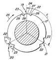
次に本発明一実施態様の切り欠き部を詳細に説明する。図2はネジ部の一螺旋を平面にしたネジ山の切り欠き部とその谷の配置説明図であり、ネジ山17の円周頂部には半径方向(放射状)内向きの切り欠き部19、20、21が設けられており、説明を簡潔にするために切り欠き部19についてのみ詳述するが、残る切り欠き部20、21も同様の形態とする。
【0012】
切り欠き部19、20、21はネジ山17の中心角度において約120°の間隔βをおいて3箇所に設けられている。一例として切り欠き部19は、互いに短い間隔をおいて配された一対のV字状あるいは三角形状の切り欠き部22、23からなり、各切り欠き部の先端はネジの中心、即ち半径方向内方へと延び、これにより切り欠き部19はW字状に形成されている。図示するごとく各切り欠き部19、20、21の半径方向の長さは螺旋ネジ17のネジ山の高さより短くなっている。
【0013】
本発明を最も効果的に実施するためのネジの軸部10の全長は最低約30mmであり、本発明によるネジの捩れ応力の見地から、中間の切り欠き部が設けられるネジ部の螺旋数はネジ軸部全長に応じて適宜選択することが好ましい。一例として、30mm(1.25インチ)から140mmの軸部を有するネジでは、3螺旋の切り欠きネジ部17を有し、約150mmから240mmの軸部を有するネジにはネジ山17は4螺旋、250mm以上の軸部を有するものには5螺旋のネジ山を設けることが好ましい。前述のようにネジ山17は円弧状に均等間隔で3箇所に切り欠き部19―21を有している。
【0014】
回転方向25から見て、切り欠き部分22、23はそれぞれ前方切欠き部分、後方切欠き部分となり、図2に示すように、各切欠き部分22、23は中央に台形の歯24を有し、各々前方縁部26、28と後方縁部27、29とを有している。
【0015】
各切欠き部分22、23の後方縁部27、前方縁部28は各々歯24のカット縁部と後縁部であり、歯24の前後の切欠き部分22、23は、切り欠き部19もしくは先の切り欠き部21の歯24により発生する削り屑を排出する空隙にもなる。
【0016】
各切り欠き部19−22のネジ山17頂点円周上の幅を合計すると、図2に示す様に、ネジ山の一螺旋円周の1/3となる。
図2の実施例では前方縁部26、28と後方縁部27、29により各々形成される切欠き部分22、23の切込み角度はα角、約90度である。後述する本発明のさらに別の実施態様(図3乃至図5参照)ではこれら前方縁部と後方縁部とで形成される切込み角度αについては図示省略するが、各実施態様において第一実施例に関連するネジの各部材については同様の符号を付した。
【0017】
次にこのネジを用いて被締結物に締結する第1実施例について簡単に説明する。
図1に示す様に、ネジを位置決めして電動ドライバーなどでネジを符号25の方向に回転しながら被締結物にねじ込むと、ネジ先11から始まる約2螺旋の第1ネジ部16には切り欠き部がないことから、ねじ込み案内を邪魔されずにネジが捩じ込まれる。次に歯24を備えた切り欠き部分22、23により構成される約5螺旋の中間ネジ部17の切り欠き部19、20、21は、前記切り欠き部分の後方縁部27、前方縁部28が各々歯24のカット縁部と後縁部の役目を果たし、被締結物を削りながら押し進む。一方歯24の前後の空隙となる切欠き部分22、23からは前記削り屑が排出されながら、ネジそのものは被締結物への食いつきがよくなり、ドライバーによるネジのトルク強度を維持しながらネジ止めに必要な力を節約できる。
【0018】
従って本発明のネジは切り欠き部の歯により被締結物を削りながら締付けられるので止めたネジが自分で緩む傾向を回避できるとともに、締付けトルク強度に対する抵抗力が強いため、ネジの頭部の破損を防止できる。
【0019】
図3は本発明の木ネジの他の実施態様における切り欠き部を示す図であり、前記実施態様とは、前方縁部26と後方縁部27とから構成される切り欠き部分22の切込み角度(図2のα角)が鋭角である点が異なる。すなわち、後方縁部27、すなわち歯24のカット縁部27は、軸部10の中心と同心の後述する参照第二円33よりも小径の参照第一円31の円周からの接線30上に配置され、他方縁部26は図示する第二参照円33の円周からの接線32上に配置されている。
従って図3に示すように、カット縁部27は図2に図示される縁部より軸部10の中心に向かって傾斜している。なお後方切欠き部分23の形状は前記切欠き部分22と対称に形成される。
【0020】
縁部27の前記傾斜の度合は円31の直径が小さくなれば大きくなり、大きくなれば小さくなる。従って縁部27が第一円31の直径が0、すなわち軸部10の中心からの接線30上に配設される場合に、縁部27の傾斜度合は最大になる。
【0021】
2つの空隙22、23を設けて歯24により発生する削り屑を排出するという利点を維持しながら引き抜きに対する抵抗度を改良するために、図3に示す実施態様における各切り欠き部19−22のネジ山17頂点円周上の幅を合計すると、ネジ山一螺旋の円周の1/3になるよう構成されている。
【0022】
図4は本発明による木ネジの別の実施態様における切り欠き部を示す図であり、前述の各実施態様と異なり、切欠き部分22、23の切込みの傾斜方向並びに形状は同一かつ非対称に構成されている。切欠き部分22において、歯24の縁部27からの接線30は軸部10の中心31から延びる線上に位置し、半径方向内方への最大傾斜角度を有している。この場合は第1、第2実施態様で詳述した第一円31の直径は0、すなわち軸部10の中心であり、縁部27は実質的に軸部の半径上に位置している。他方前方縁部26は第二円33の円周からの接線32上に形成されている。後方切欠き部分23において、前後の縁部28、29は前方切欠き部分22の各縁部26、27と同様に配設されており、前方縁部28は第二円33の円周からの接線34上に配置され、後方縁部29はネジ山17の軸部10の半径上に配置されている。図4に示すように、図2に図示する実施態様のα角度に相当する各V字型凹部の角度は約45度の鋭角に構成され、切り欠き部分22、23から構成される切り欠き部19のネジ部円周上の幅はさらに短く形成されている。
【0023】
図5は本発明による木ネジのさらに別の実施態様を示す図であり、各前後縁部26、27、28、29の角度に関しては図4において説明した実施態様と同様であるが、歯24全体の幅、すなわち切り欠き部19全体の幅がさらに短く構成されている点で異なる。この結果歯24は三角形形状に形成され切り欠き部19全体の幅をさらに狭く構成している。図5に示す切り欠き部19の幅は図示した各実施態様で最も狭いが充分繊維屑を排出できる。
【0024】
前述のように本発明のネジは、全長1インチもしくはそれ以上の全長を有する。本発明のネジは被締結物に止める際のトルクに対する抵抗を軽減する効果を有し、従来の木ネジより必要トルクを約30%以上軽減できることが発見された。これにより本発明のネジを電動ドライバーで締付けると多くの場合、軸部の破損発生を回避でき、締付けトルク強度を軽減しながら一旦位置決めされたネジが緩む傾向もなくなる。
【0025】
なお、少なくとも約1インチ以上のネジ全長に関らず、ネジ先のネジ山螺旋数(2本)並びに所定破断部の螺旋数(5本)には一定の好ましい本数があるものの、本発明の範囲を逸脱することなく、各ネジ山の螺旋回数は当該技術分野に従事する者が容易に変更できる。これらは容易に考え得る多数のネジの変更態様の1つであり、本明細書に添付する特許請求の範囲を逸脱することなく、切り欠き部の幾何学的形状や、スクリューヘッドを用いたものや、螺旋ごとの切り欠き部の数を変えるなど、様々な他の目的で前述の各実施態様と異なるネジの構造にさせてもよい。
【0026】
例えば図6に示す様に、ネジは円筒状軸部55と、ネジ先54の輪郭をなす円筒状軸部55の第1端部と、これに対して頭部端部41と合体する円筒状軸部55の第2端部とに一体成形されている。好ましくは頭部端部41は滑らかに円錐台部43になる拡大径部52を有している。螺旋状のネジ部53はネジ先54から頭部13と間隔をおいた位置まで延びている。図6に示す符号45は被締結物に対してねじ込まれるネジの回転方向を示す。
【0027】
図6に示す円筒状軸部55のネジ螺旋数は11山以上であり、図示するネジはネジ先54から始まって、一連の切り欠き部のない約3螺旋の第1ネジ部53と、次に約5螺旋の所定位置2箇所に切り欠きを備えられる中間の破断ネジ部56と、最後に第2端部近傍の3螺旋以上の第3ネジ部53とからなる滑らかな曲線にネジ切りされている。
【0028】
ネジの拡大径部52と一体成形されるネジの第2端部の円錐台部43は複数の変形凹部49を形成され、各凹部49は辺47、48を有する頭部41に滑らかに移行する複数の突出部分により仕切られている。図6に示す様に、突出部分の辺47から上壁部51と、三角形形状の垂直壁部46とを残すよう傾斜して厚みを切取ることにより円錐台部43の凹部49を形成し、この結果凹部49は突出部の辺47と緩やかに接し図示正面右側に傾斜する形状の傾斜面44を形成される。
【0029】
このようにネジを構成することにより、滑らかに湾曲するネジ切によってネジの食いつきはさらに改良され、破断ネジ部の歯から発生する削り屑を切り欠き部の切り欠き部分から排出し、さらにネジ頭部の円錐台部が凹凸形状に構成されていることから、ネジが被締結物に捩じ込まれて締付けられる際のトルクに対する強度を増してネジの破損を防止できる。
【0030】
【発明の効果】
以上要するに本発明によれば、ネジを被締結物に止めるときの良好なトルク強度を維持しながらネジ止めに必要な力を軽減するとともに、位置決めしたネジの自己緩み傾向を回避するとともに、締結具破損の可能性も回避し木材などの被締結物など繊維質被締結物へのネジの設置を容易にするネジが提供される。
【図面の簡単な説明】
【図1】本発明のネジの側面図である。
【図2】本発明の好ましい実施態様を示し、ネジ山の切り欠き部とその谷の配置を表すためにネジ部の一螺旋もしくは捩れを平面にした図1の線II−IIに関する図解断面図である。
【図3】図2に関連して本発明の別の実施態様における切り欠き部の配置を示す部分説明図である。
【図4】図3に関連して本発明のさらに別の実施態様における切り欠き部の配置を示す部分説明図である。
【図5】図3と同様に本発明のさらに別の実施態様における切り欠き部の配置を示す部分説明図である。
【図6】本発明のさらに別の実施態様におけるネジの側面図である。
【符号の説明】
10:円筒状軸部
11:ネジ先
12:頭部端部
13:頭部
14:円錐台部
15:ネジ山
25:ネジの回転方向
16:第1ネジ部
17:破断ネジ部
18:第3ネジ部
19、20、21:切り欠き部
22、23:切り欠き部分
24:歯
26、28:前方縁部
27、29:後方縁部[0001]
BACKGROUND OF THE INVENTION
The present invention relates to a wood screw, and more particularly to a self-tapping screw used to fix and fasten a fibrous material such as wood.
[0002]
[Prior art]
The conventional wood screw has a smooth continuous thread, and if the fiber to be fastened has a low fiber density or a pilot hole is prepared, the screw thread as described above Can be fastened sufficiently.
However, when fastening an object to be fastened having a relatively high fiber density, such as wood or a fibrous board, or when a pilot hole is not prepared, a high torque is required to completely screw a conventional screw. In particular, when the high torque of a screw is obtained using an electric screwdriver, the screw may be broken and the fastened object may be damaged.
[0003]
Therefore, it is preferable that the screw used for the fibrous article to be fastened has an increased resistance to pulling and loosening while avoiding the possibility of breakage and at least reducing it.
Therefore, International Publication No. WO 98/44268 discloses a structure of a wood screw for facilitating screwing into hard wood, and the thread of this screw starts substantially from the screw tip. A number of V-shaped notches are provided. The thread provided with a V-shaped cutout extends over the entire length of the screw shaft.
[0004]
On the other hand, the wood screw described in British Patent No. 1120991 is provided with a groove extending spirally over the entire length of the screw portion of the shaft portion, and many of the screw threads protrude radially outward. It is formed in the shape of a protrusion.
[0005]
Each of the above-mentioned conventional wood screws is substantially weak in torque strength of the whole screw, and is easily damaged when using an electric screwdriver, and discharges shavings generated at the cut end of each notch portion. There are insufficient gaps. Furthermore, since the notch part is provided also in the screw front-end | tip, the screwing-in guide of the screw with respect to a to-be-fastened object is obstructed.
[0006]
[Problems to be solved by the invention]
Therefore, the present invention has been made in view of such circumstances, and its purpose is to save the force of screwing into the fastened object while maintaining the best torque strength of the screw, and to avoid that the screw that is stopped loosens itself. Another object of the present invention is to provide a screw capable of easily screwing a fibrous material such as wood.
[0007]
The screw of the present invention is provided with a notch portion whose width becomes narrower inward in the radial direction only at a predetermined portion of the entire length of the screw portion. According to another feature of the invention, a W-shaped notch comprising a pair of shortly spaced V-shaped notches is formed at three locations per one screw thread of the predetermined portion. . The predetermined breaking screw portion is arranged in a shaft shape between the first end portion or the tip end of the screw portion having no notch portion and the second end portion or the head end portion.
[0008]
[Means for Solving the Problems]
The object is the matter described in the characterizing portion of claim 1, that is, the shaft portion includes at least a first end portion that forms a tip portion, a second end portion that mates with the head portion, and at least a total length of the shaft portion. A screw portion having a screw thread provided in a part of a spiral, and a predetermined portion of the total length of the screw portion is arranged at a constant interval from each other at the top of each screw thread and is directed radially inward A plurality of notches are provided, and the predetermined portion of the screw portion is positioned at an interval in the axial direction from the first end portion, and the notch is not provided on the thread of the interval portion. Achieved.
According to a second aspect of the present invention, each of the plurality of notches provided in each screw thread is formed in a W-shape, whereby each notch is located between the two notches and between them. It is preferable to be comprised from a tooth-like part.
According to a third aspect of the present invention, it is preferable that the predetermined portion having the notch portion is located at an intermediate portion of the entire screw portion.
The total length of the shaft portion is at least about 30 mm, and the first end is threaded with about 2 spirals not provided with a notch, and the predetermined portion and Preferably, a plurality of threads that are not provided with notches are provided between the second ends.
According to a sixth aspect of the present invention, the predetermined portion is preferably provided with notches having a width that is narrower inward in the radial direction at approximately three locations per spiral.
According to a seventh aspect of the present invention, it is preferable that the total width of each notch portion on the periphery of each screw thread top is about 1/3 or less of the entire circumference of one spiral.
The total length of the shaft portion is at least about 30 mm, and the notch portion includes a front edge portion and a rear edge portion in a screwing rotation direction of the fastened object. It is composed of a notch portion and a rear notch portion, the rear edge portion of the front notch portion forms a cut edge portion of the central tooth, and the front edge portion of the rear notch portion is a rear edge of the central tooth It is preferable that gaps are formed before and after the teeth by forming the portion.
According to a ninth aspect of the present invention, it is preferable that each notch portion has a triangular shape in which a radially inward portion forms an angle of 90 degrees.
As shown in
The front edge portion of the front notch portion and the rear edge portion of the rear notch portion are respectively in contact with the circumference of a virtual second circle concentric with the center of the screw shaft portion. Located on the line, the tooth cut edge is located on the tangent to the circumference of the virtual first circle concentric with the center of the shaft, and the notch part forms an acute angle in the radially inward direction It is preferable to make a triangular shape.
As shown in
As shown in
[0009]
BEST MODE FOR CARRYING OUT THE INVENTION
An embodiment of the present invention will be described below with reference to the accompanying drawings.
In each of the other embodiments of the present invention to be described later, the same members will be described with the same reference numerals.
FIG. 1 is a side view showing an embodiment of a wood screw according to the present invention, and FIG. 2 is an arrangement of notches and valleys of a thread according to an embodiment of the present invention in which one spiral of a screw portion is a plane. FIG. In FIG. 1, the screw has a
[0010]
The overall length of the screw of the illustrated embodiment is 250 mm, and the threaded spiral or the number of rotations of the
[0011]
Next, the notch part of one embodiment of the present invention will be described in detail. FIG. 2 is an explanatory view of the arrangement of a thread notch portion and a trough thereof, in which one spiral of the thread portion is a flat surface, and a radial (radially)
[0012]
The
[0013]
The total length of the
[0014]
When viewed from the
[0015]
The
[0016]
The total width of the notches 19-22 on the circumference of the top of the
In the embodiment of FIG. 2, the cut angle of the notched
[0017]
Next, a brief description will be given of a first embodiment in which the screw is used to fasten an object to be fastened.
As shown in FIG. 1, when the screw is positioned and screwed into an object to be fastened while rotating the screw in the direction of
[0018]
Therefore, since the screw of the present invention is tightened while cutting the object to be fastened with the teeth of the notch portion, it is possible to avoid the tendency of the screw that has been loosened by itself, and the resistance to the tightening torque strength is strong. Can be prevented.
[0019]
FIG. 3 is a view showing a notch portion in another embodiment of the wood screw according to the present invention. The embodiment is a cut angle of a
Therefore, as shown in FIG. 3, the
[0020]
The degree of inclination of the
[0021]
In order to improve the resistance to pulling out while maintaining the advantage of providing two
[0022]
FIG. 4 is a view showing a notch in another embodiment of the wood screw according to the present invention. Unlike the above-described embodiments, the inclining direction and shape of the
[0023]
FIG. 5 is a view showing still another embodiment of the wood screw according to the present invention. The angles of the front and
[0024]
As described above, the screw of the present invention has a total length of 1 inch or more. It has been discovered that the screw of the present invention has the effect of reducing the resistance to torque when it is fastened to the object to be fastened, and the required torque can be reduced by about 30% or more than conventional wood screws. As a result, when the screw of the present invention is tightened with an electric screwdriver, in many cases, the shaft portion can be prevented from being broken, and the once-positioned screw does not tend to loosen while reducing the tightening torque strength.
[0025]
It should be noted that although there are certain preferred numbers for the number of screw threads (2) of the screw tip and the number of threads (5) of the predetermined breaking portion, regardless of the total length of the screw of at least about 1 inch or more, Without departing from the scope, the number of spirals of each thread can be easily changed by those skilled in the art. These are one of many screw modifications that can be easily thought of, and use notch geometry or screw heads without departing from the scope of the claims appended hereto. Alternatively, the screw structure may be different from those of the above-described embodiments for various other purposes such as changing the number of notches for each spiral.
[0026]
For example, as shown in FIG. 6, the screw has a
[0027]
The number of screw spirals of the
[0028]
The
[0029]
By constructing the screw in this way, the biting of the screw is further improved by the threading that smoothly curves, and the shavings generated from the teeth of the fracture screw part are discharged from the notch part of the notch part, and further the screw head Since the truncated cone part of the part is configured to have an uneven shape, the strength against torque when the screw is screwed into the object to be fastened and tightened can be prevented, and damage to the screw can be prevented.
[0030]
【The invention's effect】
In short, according to the present invention, the force required for screwing is reduced while maintaining a good torque strength when the screw is fastened to the object to be fastened, the self-loosening tendency of the positioned screw is avoided, and the fastener A screw is provided that avoids the possibility of breakage and facilitates the installation of the screw on a fibrous fastening object such as a wood fastening object.
[Brief description of the drawings]
FIG. 1 is a side view of a screw according to the present invention.
2 illustrates a preferred embodiment of the present invention and is a cross-sectional view taken along line II-II of FIG. 1 with one helix or twist of the threaded portion planar to represent the arrangement of the thread notch and its troughs. It is.
FIG. 3 is a partial explanatory view showing the arrangement of notches in another embodiment of the present invention in relation to FIG. 2;
FIG. 4 is a partial explanatory view showing the arrangement of notches in still another embodiment of the present invention in relation to FIG. 3;
FIG. 5 is a partial explanatory view showing the arrangement of notches in still another embodiment of the present invention, similar to FIG. 3;
FIG. 6 is a side view of a screw according to still another embodiment of the present invention.
[Explanation of symbols]
10: cylindrical shaft portion 11: screw tip 12: head end portion 13: head portion 14: truncated cone portion 15: screw thread 25: screw rotation direction 16: first screw portion 17: fracture screw portion 18:
Claims (13)
Applications Claiming Priority (2)
| Application Number | Priority Date | Filing Date | Title |
|---|---|---|---|
| CA2234040 | 1998-04-03 | ||
| CA002234040A CA2234040A1 (en) | 1998-04-03 | 1998-04-03 | Screw for use as a fastener in fibrous material such as wood |
Publications (2)
| Publication Number | Publication Date |
|---|---|
| JP2000027830A JP2000027830A (en) | 2000-01-25 |
| JP4237862B2 true JP4237862B2 (en) | 2009-03-11 |
Family
ID=4162294
Family Applications (1)
| Application Number | Title | Priority Date | Filing Date |
|---|---|---|---|
| JP09769299A Expired - Lifetime JP4237862B2 (en) | 1998-04-03 | 1999-04-05 | Screws used as fasteners for fiber materials such as wood |
Country Status (10)
| Country | Link |
|---|---|
| US (1) | US6152666A (en) |
| EP (1) | EP0947715B1 (en) |
| JP (1) | JP4237862B2 (en) |
| CN (1) | CN1188608C (en) |
| AT (1) | ATE234432T1 (en) |
| CA (1) | CA2234040A1 (en) |
| DE (1) | DE69905783T2 (en) |
| ES (1) | ES2190626T3 (en) |
| HK (1) | HK1020604A1 (en) |
| TW (1) | TW411383B (en) |
Families Citing this family (46)
| Publication number | Priority date | Publication date | Assignee | Title |
|---|---|---|---|---|
| US20030031528A1 (en) * | 2001-07-31 | 2003-02-13 | Kram Guenther Reinhard | Multi-mate fastener |
| KR20030043160A (en) * | 2001-11-27 | 2003-06-02 | 김중배 | A screw for fixing plastic |
| JP2003222116A (en) * | 2002-01-31 | 2003-08-08 | Honda Motor Co Ltd | Self-tapping bolt |
| JP2003278729A (en) * | 2002-03-27 | 2003-10-02 | Aoyama Seisakusho Co Ltd | Notched screw part and method of manufacturing the same |
| US7017952B2 (en) * | 2002-06-21 | 2006-03-28 | Maclean-Fogg Company | Fluid connector |
| WO2004031599A2 (en) * | 2002-10-02 | 2004-04-15 | Aoyama Seisakusho Co., Ltd. | Tapping screw |
| US7037204B2 (en) * | 2002-12-30 | 2006-05-02 | Barun Majumdar | Standard threaded torque fastener with novel indentation patterns to enhance torque and self-locking capabilities |
| JP4225546B2 (en) * | 2003-10-09 | 2009-02-18 | 株式会社青山製作所 | Tapping screw |
| US20050175432A1 (en) * | 2004-02-09 | 2005-08-11 | Kuo-Tai Su | Screw |
| DE202004002877U1 (en) * | 2004-02-25 | 2005-06-30 | A-Z Ausrüstung Und Zubehör Gmbh & Co. Kg | Thread forming screw |
| DE102004021484B4 (en) * | 2004-04-30 | 2018-11-29 | Böllhoff Verbindungstechnik GmbH | Method for producing a connection arrangement |
| DE102004058812B4 (en) * | 2004-12-07 | 2006-09-28 | Institut für Holztechnologie Dresden gGmbH | Tool for creating cavities in materials, preferably sandwich panels |
| US7163366B2 (en) * | 2005-01-05 | 2007-01-16 | Pei-Hua Chen | Screw with two types of threads |
| CA2510200A1 (en) * | 2005-06-16 | 2006-12-16 | Walther, Mirco | Screw for use in concrete |
| US20070065255A1 (en) * | 2005-09-21 | 2007-03-22 | A-Stainless International Co., Ltd. | Thread section for screws |
| TWM294585U (en) * | 2006-01-09 | 2006-07-21 | Easylink Ind Co Ltd | Screw structure |
| DE102006000269A1 (en) * | 2006-06-02 | 2007-12-06 | Hilti Ag | Thread-forming screw |
| US7798756B2 (en) * | 2007-03-24 | 2010-09-21 | Essence Method Refine Co., Ltd. | Screw with waved thread |
| US20110176888A1 (en) * | 2010-01-20 | 2011-07-21 | Powers Fasteners, Inc. | Masonry anchor |
| WO2016000784A1 (en) | 2014-07-03 | 2016-01-07 | Stryker Trauma Gmbh | Conical end cap for intramedullary nail |
| TWM489214U (en) * | 2014-07-31 | 2014-11-01 | King Point Enterprise Co Ltd | Cement expansion bolt |
| US9581183B2 (en) | 2015-02-17 | 2017-02-28 | The Hillman Group, Inc. | Screw-type fastener |
| KR101722335B1 (en) * | 2015-10-23 | 2017-04-11 | 서동인 | Manufacturing method of the wood screw |
| TWM519685U (en) * | 2015-12-21 | 2016-04-01 | Shin Chun Entpr Co Ltd | Locking fastener |
| US10436238B2 (en) | 2016-04-04 | 2019-10-08 | The Hillman Group, Inc. | Screw type fastener |
| AU201614800S (en) * | 2016-08-31 | 2016-09-30 | Illinois Tool Works | A screw fastener |
| AU201614802S (en) | 2016-08-31 | 2016-09-30 | Illinois Tool Works | A screw fastener |
| US11389205B2 (en) | 2016-11-30 | 2022-07-19 | Stryker European Operations Holdings Llc | Spinal fastener with serrated thread |
| USD828149S1 (en) * | 2016-11-30 | 2018-09-11 | Hyundai Motor Company | Bolt |
| USD863050S1 (en) * | 2017-04-19 | 2019-10-15 | Ying-Chin CHAO | Screw |
| USD845118S1 (en) * | 2017-04-20 | 2019-04-09 | A-Stainless International Co., Ltd. | Screw |
| USD854404S1 (en) * | 2017-06-16 | 2019-07-23 | Masterpiece Hardware Industrial Co., Ltd. | Screw |
| USD898196S1 (en) | 2017-07-10 | 2020-10-06 | Stryker European Holdings I, Llc | Spinal fastener with serrated thread |
| US11105361B2 (en) | 2017-11-03 | 2021-08-31 | The Hillman Group, Inc. | Screw-type fastener |
| WO2019199430A1 (en) | 2018-04-09 | 2019-10-17 | The Hillman Group, Inc. | Screw-type fastener for concrete and hurricane resistance applications |
| US20200102980A1 (en) * | 2018-09-28 | 2020-04-02 | Kuo-Tai Hsu | Wood screw |
| US11253060B2 (en) | 2018-10-31 | 2022-02-22 | American Woodmark Corporation | Modular enclosure system |
| US11199056B2 (en) * | 2019-02-06 | 2021-12-14 | James Jing Yao | Threaded coupling for percussion drill bit |
| US11419652B2 (en) * | 2019-04-26 | 2022-08-23 | Warsaw Orthopedic, Inc. | Thread form for bone screw |
| CA203180S (en) | 2020-11-26 | 2022-11-10 | Illinois Tool Works | Fastener |
| CN112727892B (en) * | 2020-12-28 | 2023-03-28 | 河北中车陆星防松技术有限公司 | Anti-backspin nut and manufacturing tool and method |
| CN112727889B (en) * | 2020-12-28 | 2023-07-14 | 福建省华盖机械制造有限公司 | Anti-convolution screw and nut combination |
| CN112747025B (en) * | 2020-12-28 | 2023-05-09 | 江西海威智能装备有限公司 | Anti-backspin screw, manufacturing tool and manufacturing method |
| USD1013498S1 (en) | 2021-02-03 | 2024-02-06 | Illinois Tool Works Inc. | Fastener |
| US12085107B2 (en) * | 2021-03-30 | 2024-09-10 | The Hillman Group, Inc. | Structural screw |
| KR102730742B1 (en) * | 2023-10-19 | 2024-11-18 | (주)문주하드웨어 | bolt |
Family Cites Families (20)
| Publication number | Priority date | Publication date | Assignee | Title |
|---|---|---|---|---|
| FR385906A (en) * | 1908-01-03 | 1908-05-30 | Walter Christopher Jordan | Improvements to screws |
| GB667051A (en) * | 1949-09-16 | 1952-02-20 | Gkn Group Services Ltd | Improvements in or relating to self-tapping screws |
| BE630098A (en) * | 1962-03-31 | |||
| GB1120991A (en) * | 1965-02-02 | 1968-07-24 | G K N Screws And Fasteners Ltd | Improvements relating to wood screws |
| US3472119A (en) * | 1966-06-29 | 1969-10-14 | Hubbell Inc Harvey | Thread forming screw and method of making same |
| US3982575A (en) * | 1974-12-23 | 1976-09-28 | Standard Pressed Steel Co. | Thread forming self-locking screw |
| US3937119A (en) * | 1974-12-23 | 1976-02-10 | Illinois Tool Works, Inc. | Masonry anchor device |
| DE2815247A1 (en) * | 1978-04-08 | 1979-10-11 | Fischer Artur Dr H C | Masonry bolt with drill tip - has cutting edge on radial projection of pilot shank to enlarge hole |
| US4842467A (en) * | 1984-08-24 | 1989-06-27 | Yamashina Seiko-Sho, Ltd. | Concrete screw |
| US5267423A (en) * | 1987-08-03 | 1993-12-07 | Giannuzzi Louis | Self-drilling anchor and bearing plate assembly |
| GB8819820D0 (en) * | 1988-08-20 | 1988-09-21 | Tucker Fasteners Ltd | Anchors for fixing to dense concrete masonry &c |
| DE8905189U1 (en) * | 1989-04-25 | 1989-06-15 | Rommel, Erwin, 4320 Hattingen | Thread forming screw |
| JPH03103607A (en) * | 1989-09-13 | 1991-04-30 | Nitto Seiko Co Ltd | Thread forming screw |
| GB9004520D0 (en) * | 1990-02-28 | 1990-04-25 | Tappex Thread Inserts Ltd | Fastener |
| US5340254A (en) * | 1992-01-31 | 1994-08-23 | Textron Inc. | Thread forming screw for forming an internal thread in a low ductility material |
| US5833415A (en) * | 1992-09-22 | 1998-11-10 | Titan Technology, Inc. | Anchor insert improvement |
| EP0625400A1 (en) * | 1993-05-04 | 1994-11-23 | LUDWIG HETTICH SCHRAUBENFABRIK GmbH & Co. | Tool for the formation of an internal thread |
| DE29504559U1 (en) * | 1995-03-17 | 1996-02-15 | Sawatzki, Günter, 48249 Dülmen | Self-drilling screw |
| DE19532874A1 (en) * | 1995-09-06 | 1997-03-13 | Az Ausruest Zubehoer Gmbh | Thread forming connector |
| DE29705916U1 (en) * | 1997-04-03 | 1998-07-30 | A-Z Ausrüstung und Zubehör GmbH & Co. KG, 45525 Hattingen | Self-piercing and thread-forming connecting element |
-
1998
- 1998-04-03 CA CA002234040A patent/CA2234040A1/en not_active Abandoned
- 1998-12-08 TW TW087120345A patent/TW411383B/en not_active IP Right Cessation
-
1999
- 1999-03-16 US US09/268,790 patent/US6152666A/en not_active Expired - Lifetime
- 1999-03-30 EP EP99106524A patent/EP0947715B1/en not_active Expired - Lifetime
- 1999-03-30 DE DE69905783T patent/DE69905783T2/en not_active Expired - Lifetime
- 1999-03-30 AT AT99106524T patent/ATE234432T1/en active
- 1999-03-30 ES ES99106524T patent/ES2190626T3/en not_active Expired - Lifetime
- 1999-04-02 CN CN99104727.3A patent/CN1188608C/en not_active Expired - Lifetime
- 1999-04-05 JP JP09769299A patent/JP4237862B2/en not_active Expired - Lifetime
- 1999-11-29 HK HK99105523A patent/HK1020604A1/en not_active IP Right Cessation
Also Published As
| Publication number | Publication date |
|---|---|
| CN1231391A (en) | 1999-10-13 |
| US6152666A (en) | 2000-11-28 |
| ES2190626T3 (en) | 2003-08-01 |
| EP0947715B1 (en) | 2003-03-12 |
| JP2000027830A (en) | 2000-01-25 |
| TW411383B (en) | 2000-11-11 |
| DE69905783T2 (en) | 2004-02-12 |
| ATE234432T1 (en) | 2003-03-15 |
| HK1020604A1 (en) | 2000-05-12 |
| DE69905783D1 (en) | 2003-04-17 |
| EP0947715A1 (en) | 1999-10-06 |
| CN1188608C (en) | 2005-02-09 |
| CA2234040A1 (en) | 1999-10-03 |
Similar Documents
| Publication | Publication Date | Title |
|---|---|---|
| JP4237862B2 (en) | Screws used as fasteners for fiber materials such as wood | |
| AU2002300050B2 (en) | Multi-mate fastener | |
| CA2184768C (en) | Thread-forming joining element | |
| EP0999371B1 (en) | Enhanced strength screw-type masonry anchor | |
| EP0579816B1 (en) | Self drilling screw | |
| US5961267A (en) | Thread forming fastener | |
| US11149776B2 (en) | Screw structure | |
| EP0559381A1 (en) | Concrete fastener | |
| US20020031409A1 (en) | Solid end mill | |
| US20230392636A1 (en) | Concrete fastener | |
| US10801539B2 (en) | Screw capable of reducing drilling torque | |
| EP4074992B1 (en) | Wood screw | |
| JP3394259B2 (en) | Improvement of anchor insert | |
| EP1850016B1 (en) | Saw Tooth Screw | |
| JPH04228912A (en) | Clamping tool | |
| CA2267572C (en) | Screw for use as a fastener in fibrous material such as wood | |
| US20060024147A1 (en) | Screw for hard materials | |
| US20230392637A1 (en) | Concrete fastener | |
| EP3508739B1 (en) | Screw capable of reducing drilling torque | |
| JP4219247B2 (en) | Tapping screw | |
| TWI814841B (en) | Screw | |
| WO2025042988A1 (en) | Concrete fastener | |
| CN119267406A (en) | Screw | |
| US20210088068A1 (en) | Quick fastening screw | |
| JPH11230141A (en) | Wood screw |
Legal Events
| Date | Code | Title | Description |
|---|---|---|---|
| A621 | Written request for application examination |
Free format text: JAPANESE INTERMEDIATE CODE: A621 Effective date: 20050428 |
|
| RD02 | Notification of acceptance of power of attorney |
Free format text: JAPANESE INTERMEDIATE CODE: A7422 Effective date: 20050428 |
|
| A521 | Request for written amendment filed |
Free format text: JAPANESE INTERMEDIATE CODE: A821 Effective date: 20050428 |
|
| A977 | Report on retrieval |
Free format text: JAPANESE INTERMEDIATE CODE: A971007 Effective date: 20080522 |
|
| A131 | Notification of reasons for refusal |
Free format text: JAPANESE INTERMEDIATE CODE: A131 Effective date: 20080603 |
|
| A521 | Request for written amendment filed |
Free format text: JAPANESE INTERMEDIATE CODE: A523 Effective date: 20080807 |
|
| TRDD | Decision of grant or rejection written | ||
| A01 | Written decision to grant a patent or to grant a registration (utility model) |
Free format text: JAPANESE INTERMEDIATE CODE: A01 Effective date: 20081209 |
|
| A01 | Written decision to grant a patent or to grant a registration (utility model) |
Free format text: JAPANESE INTERMEDIATE CODE: A01 |
|
| A61 | First payment of annual fees (during grant procedure) |
Free format text: JAPANESE INTERMEDIATE CODE: A61 Effective date: 20081219 |
|
| R150 | Certificate of patent or registration of utility model |
Free format text: JAPANESE INTERMEDIATE CODE: R150 |
|
| FPAY | Renewal fee payment (event date is renewal date of database) |
Free format text: PAYMENT UNTIL: 20111226 Year of fee payment: 3 |
|
| FPAY | Renewal fee payment (event date is renewal date of database) |
Free format text: PAYMENT UNTIL: 20121226 Year of fee payment: 4 |
|
| FPAY | Renewal fee payment (event date is renewal date of database) |
Free format text: PAYMENT UNTIL: 20121226 Year of fee payment: 4 |
|
| FPAY | Renewal fee payment (event date is renewal date of database) |
Free format text: PAYMENT UNTIL: 20131226 Year of fee payment: 5 |
|
| R250 | Receipt of annual fees |
Free format text: JAPANESE INTERMEDIATE CODE: R250 |
|
| R250 | Receipt of annual fees |
Free format text: JAPANESE INTERMEDIATE CODE: R250 |
|
| R250 | Receipt of annual fees |
Free format text: JAPANESE INTERMEDIATE CODE: R250 |
|
| R250 | Receipt of annual fees |
Free format text: JAPANESE INTERMEDIATE CODE: R250 |
|
| R250 | Receipt of annual fees |
Free format text: JAPANESE INTERMEDIATE CODE: R250 |
|
| R250 | Receipt of annual fees |
Free format text: JAPANESE INTERMEDIATE CODE: R250 |
|
| EXPY | Cancellation because of completion of term |