JP4222345B2 - Steering control device - Google Patents
Steering control device Download PDFInfo
- Publication number
- JP4222345B2 JP4222345B2 JP2005223170A JP2005223170A JP4222345B2 JP 4222345 B2 JP4222345 B2 JP 4222345B2 JP 2005223170 A JP2005223170 A JP 2005223170A JP 2005223170 A JP2005223170 A JP 2005223170A JP 4222345 B2 JP4222345 B2 JP 4222345B2
- Authority
- JP
- Japan
- Prior art keywords
- steering
- vehicle
- rudder
- respect
- control
- Prior art date
- Legal status (The legal status is an assumption and is not a legal conclusion. Google has not performed a legal analysis and makes no representation as to the accuracy of the status listed.)
- Expired - Fee Related
Links
Images


Landscapes
- Steering Control In Accordance With Driving Conditions (AREA)
- Power Steering Mechanism (AREA)
Description
本発明は、車両の操舵制御装置の技術分野に関する。 The present invention relates to a technical field of a vehicle steering control device.
この種の技術分野において、車速に応じてステアリングギア比を変化させる技術が提案されている(例えば、特許文献1参照)。特許文献1に開示された車両用舵角比可変操舵装置(以下、「従来の技術」と称する)によれば、車速が低速までの領域ではステアリングギア比を最小にし、車速が低速から中速までの領域では車速に対してヨー角速度が一定となるステアリングギア比よりも小さいステアリングギア比にし、車速が高速の領域では、車速に対してヨー角速度が一定となるステアリングギア比とすることによって、旋回時のステアリング操作性を向上させることが可能であるとされている。 In this type of technical field, a technique for changing the steering gear ratio in accordance with the vehicle speed has been proposed (see, for example, Patent Document 1). According to the vehicle steering angle ratio variable steering device disclosed in Patent Document 1 (hereinafter referred to as “prior art”), the steering gear ratio is minimized in the region where the vehicle speed is low, and the vehicle speed is changed from low to medium. By making the steering gear ratio smaller than the steering gear ratio at which the yaw angular velocity is constant with respect to the vehicle speed in the region up to, and by setting the steering gear ratio at which the yaw angular velocity is constant with respect to the vehicle speed in the region where the vehicle speed is high, It is said that the steering operability during turning can be improved.
尚、ハンドル角に対する車輪の転舵角の応答特性を変更する技術も提案されている(例えば、特許文献2参照)。 In addition, the technique which changes the response characteristic of the steering angle of the wheel with respect to a steering wheel angle is also proposed (for example, refer patent document 2).
また、車速に対する舵角比特性を切り替え、運転者の運転状態に応じて最適の操舵フィーリングを得る技術も提案されている(例えば、特許文献3参照)。 In addition, a technique has been proposed in which the steering angle ratio characteristic with respect to the vehicle speed is switched to obtain an optimum steering feeling according to the driving state of the driver (see, for example, Patent Document 3).
更に、操舵トルクに対応すべき規範操舵角と実操舵角の差を小さくする技術も提案されている(例えば、特許文献4参照)。 Furthermore, a technique for reducing the difference between the standard steering angle and the actual steering angle that should correspond to the steering torque has been proposed (see, for example, Patent Document 4).
従来の技術において、操舵トルクに対するヨー応答の特性は固定されている。従って、ステアリングギア比を変えることによって操作性を向上し得たとしても、運転者が感じるドライバビリティは変化することがない。即ち、従来の技術には、多種多様な運転者の感性に応じた操舵特性を実現し難いという技術的な問題点がある。 In the prior art, the characteristic of the yaw response to the steering torque is fixed. Therefore, even if the operability can be improved by changing the steering gear ratio, the drivability felt by the driver does not change. That is, the conventional technique has a technical problem that it is difficult to realize a steering characteristic according to the sensitivity of a wide variety of drivers.
本発明は、上述した問題点に鑑みてなされたものであり、運転者の感性に応じた操舵特性を実現し得る操舵制御装置を提供することを課題とする。 The present invention has been made in view of the above-described problems, and an object of the present invention is to provide a steering control device that can realize a steering characteristic according to the sensitivity of the driver.
上述した課題を解決するため、本発明に係る操舵制御装置は、車両における、操舵トルクに対応する、操舵操作に対する該車両の旋回の度合いを規定する舵の効きを特定する第1特定手段と、前記操舵トルクに対応する舵の効きの目標値を、所望の前記操舵トルクに対する前記舵の効きの変化特性に合致するように設定する目標値設定手段と、前記特定された操舵トルクに対応する舵の効きが、前記設定された目標値となるように前記車両の動作条件を制御する制御手段とを具備することを特徴とする。 In order to solve the above-described problem, a steering control device according to the present invention includes a first specifying unit that specifies the effectiveness of a rudder that defines the degree of turning of the vehicle with respect to a steering operation corresponding to a steering torque in the vehicle , Target value setting means for setting a rudder effectiveness target value corresponding to the steering torque so as to match a change characteristic of the rudder effectiveness with respect to the desired steering torque, and a rudder corresponding to the specified steering torque Control means for controlling the operating condition of the vehicle so that the effectiveness of the vehicle becomes the set target value.
本発明に係る操舵制御装置によれば、その動作時には、第1特定手段によって、操舵トルクに対応する舵の効きが特定される。 According to the steering control device of the present invention, during the operation, the effectiveness of the rudder corresponding to the steering torque is specified by the first specifying means.
本発明に係る「舵の効き」とは、運転者の操舵操作に対する車両の旋回度合いを包括する概念であり、係る概念が担保される限りにおいて舵の効きとは如何なる物理量或いは車両における状態量によって規定されてもよい。例えば、単位ハンドル角当りのヨーレートとして規定されていてもよい。 The “effectiveness of the rudder” according to the present invention is a concept encompassing the degree of turning of the vehicle with respect to the driver's steering operation, and as long as such a concept is secured, the effectiveness of the rudder depends on any physical quantity or state quantity in the vehicle. It may be specified. For example, it may be defined as a yaw rate per unit handle angle.
また、本発明において「特定する」とは、例えば物理的、機械的、電気的又は化学的な手法によって直接的又は間接的に検出することの他に、例えば物理的、機械的、電気的又は化学的な手法によって直接的又は間接的に検出された何らかの値に基づいて推定、推測、予測又は決定することを含む概念である。 Further, in the present invention, “identify” means, for example, physical, mechanical, electrical or chemical detection in addition to direct or indirect detection by physical, mechanical, electrical or chemical methods. It is a concept including estimation, estimation, prediction or determination based on some value detected directly or indirectly by a chemical method.
操舵トルクに対応する舵の効きは、係る概念の範囲においてどのように特定されてもよい。例えば、操舵トルクに対応する舵の効きを規定する値を直接的に又は間接的に検出してもよいし、操舵トルク及び舵の効きが夫々個別に検出可能である場合には、これら個別に検出された値を相互に照合することによって操舵トルクに対応する舵の効きが特定されてもよい。 The effectiveness of the rudder corresponding to the steering torque may be specified in any way within the concept. For example, the value defining the effectiveness of the rudder corresponding to the steering torque may be detected directly or indirectly, and when the steering torque and the effectiveness of the rudder can be detected individually, these values can be individually detected. The effectiveness of the rudder corresponding to the steering torque may be specified by comparing the detected values with each other.
尚、操舵トルクに対応する舵の効きを特定するタイミング及びその周期は何ら限定されない。しかしながら、運転者の感性と好適なリニア性を担保する観点からは、リアルタイムに或いはそれとみなし得るタイミング及び周期で特定されるのが好ましい。 In addition, the timing and the period which specify the effectiveness of the rudder corresponding to a steering torque are not limited at all. However, from the viewpoint of ensuring the driver's sensibility and suitable linearity, it is preferably specified in real time or at a timing and period that can be regarded as such.
ここで特に、操舵トルクに対応する舵の効きの変化特性(即ち、舵の効きの操舵トルクに対する軌跡)は車両の操舵特性を方向付ける大きな要素であり、例えば、操舵特性をスポーティに設定することも、穏やかに設定することも可能である。然るに、例えば従来の技術などでは、操舵トルクに対する舵の効きの変化特性は、ステアリングギア比を所定値に設定した結果として得られる固定値であるから、運転者の多様な嗜好各々に対応することは事実上不可能であり、必ずしも運転者各々に適した操舵特性が実現され得ない。 In particular, the change characteristic of the rudder effectiveness corresponding to the steering torque (that is, the trajectory of the rudder effectiveness with respect to the steering torque) is a large element that directs the steering characteristic of the vehicle. For example, the steering characteristic is set to be sporty. It is also possible to set gently. However, in the conventional technique, for example, the change characteristic of the steering effectiveness with respect to the steering torque is a fixed value obtained as a result of setting the steering gear ratio to a predetermined value, and therefore corresponds to each of the various preferences of the driver. Is practically impossible, and a steering characteristic suitable for each driver cannot always be realized.
そこで、本発明に係る操舵制御装置は、以下の如くにして係る問題点を解決している。即ち、本発明に係る操舵制御装置によれば、その動作時には更に、目標値設定手段によって、操舵トルクに対応する舵の効きの目標値が設定される。この際、目標値設定手段は、所望の操舵トルクに対する舵の効きの変化特性に合致するように目標値を設定する。 Therefore, the steering control device according to the present invention solves the problems as follows. That is, according to the steering control apparatus of the present invention, the target value of the rudder effect corresponding to the steering torque is further set by the target value setting means during the operation. At this time, the target value setting means sets the target value so as to match the change characteristic of the rudder effectiveness with respect to the desired steering torque.
ここで、「所望の変化特性」とは、操舵トルクに対する舵の効きの変化特性である限りにおいて何ら限定されない。例えば、操舵トルクと舵の効きとがリニアに変化するような変化特性であってもよいし、操舵トルクに対し舵の効きが二次曲線的に変化する変化特性であってもよい。このような所望の変化特性は、例えば、運転者が何らかの操作手段を介して適宜設定してもよいし、運転者が予め設定された複数の変化特性の中から一の変化特性を選択してもよい。 Here, the “desired change characteristic” is not limited as long as it is a change characteristic of the effectiveness of the rudder with respect to the steering torque. For example, it may be a change characteristic in which the steering torque and the effectiveness of the rudder change linearly, or may be a change characteristic in which the effect of the rudder changes in a quadratic curve with respect to the steering torque. Such a desired change characteristic may be appropriately set by the driver through some operation means, for example, or the driver selects one change characteristic from a plurality of preset change characteristics. Also good.
尚、「合致するように」とは、少なくともこのように所望の変化特性を目標とする目標値の設定が何らなされない場合と比較して、操舵トルクに対応する舵の効きを、幾らかなりとも所望の変化特性に漸近させ得る限りにおいて、必ずしも厳密に所望の変化特性と一致しておらずともよい趣旨である。 Note that “to match” means that the effectiveness of the rudder corresponding to the steering torque is considerably more than at least when the target value for setting the desired change characteristic is not set. As long as it can be asymptotic to the desired change characteristic, it is not necessarily exactly the same as the desired change characteristic.
このように操舵トルクに対応する舵の効きの目標値が設定されると、制御手段の作用により、第1特定手段によって特定された操舵トルクに対応する舵の効きが、この設定された目標値となるように車両の動作条件が制御される。 When the rudder effectiveness target value corresponding to the steering torque is set in this manner, the rudder effectiveness corresponding to the steering torque specified by the first specifying means is set to the set target value by the action of the control means. The operating conditions of the vehicle are controlled so that
ここで、「車両の動作条件」とは、車両の動作特性を規定する物理量又は制御量或いはこれらの変化特性などであって、且つ操舵トルクに対応する舵の効きを変化させ得る動作条件である限りにおいて何ら限定されない。 Here, the “vehicle operating condition” is a physical quantity or control quantity that defines the operating characteristics of the vehicle, or a change characteristic thereof, and is an operating condition that can change the effectiveness of the rudder corresponding to the steering torque. It is not limited at all.
尚、「目標値となるように」とは、このような制御の結果、必ずしも特定される操舵トルクに対応する舵の効きが目標値と一致せずともよい趣旨であり、このような制御が何らなされない場合と比較して、特定される操舵トルクに対応する舵の効きが幾らかなりとも目標値に漸近することを含む概念である。 Note that “so as to achieve the target value” means that the effect of the rudder corresponding to the specified steering torque does not necessarily coincide with the target value as a result of such control. This is a concept including that the effectiveness of the rudder corresponding to the specified steering torque is asymptotically close to the target value as compared with the case where nothing is done.
このように、本発明に係る操舵制御装置によれば、操舵トルクに対応する舵の効きは、所望の操舵トルクに対応する舵の効きの変化特性に合致するように制御される。従って、目標たる所望の変化特性の設定如何によって、操舵トルクに対応する舵の効きを比較的自由に変化させることが可能となる。即ち、運転者の感性に応じた操舵特性を実現することが可能となるのである。 As described above, according to the steering control device of the present invention, the effectiveness of the rudder corresponding to the steering torque is controlled so as to match the change characteristic of the effectiveness of the rudder corresponding to the desired steering torque. Therefore, the effectiveness of the rudder corresponding to the steering torque can be changed relatively freely depending on the setting of the desired desired change characteristic. That is, it is possible to realize a steering characteristic according to the driver's sensitivity.
本発明に係る操舵制御装置の一の態様では、前記目標値設定手段は、前記目標値を、予め設定された複数の前記変化特性の中から前記所望の変化特性として選択された一の前記変化特性に合致するように設定する。 In one aspect of the steering control device according to the present invention, the target value setting means has the target value selected as the desired change characteristic from the plurality of preset change characteristics. Set to match the characteristics.
この態様によれば、操舵トルクに対する舵の効きの変化特性は、予め複数設定されており、このうち一の変化特性に合致するように目標値が設定されるため、目標値設定手段の負荷が軽減される。 According to this aspect, the change characteristics of the effectiveness of the rudder with respect to the steering torque are set in advance, and the target value is set so as to match one of the change characteristics. It is reduced.
また、係る複数の変化特性を、予め実験的に、経験的に、或いはシミュレーションなどに基づいて、多数の運転者の嗜好を満たし得るものに設定しておくことによって、運転者の感性に応じた操舵特性が効率的に実現される。 In addition, by setting such a plurality of change characteristics in advance so as to satisfy the preferences of a large number of drivers based on experiments, experience, simulations, or the like, according to the sensitivity of the driver. Steering characteristics are efficiently realized.
本発明に係る操舵制御装置の他の態様では、前記複数の変化特性各々を表すものとして予め設定される複数のマップを記憶する記憶手段を更に具備し、前記目標値設定手段は、前記目標値を、前記複数のマップの中から前記一の変化特性に対応するものとして選択されたマップに基づいて設定する。 In another aspect of the steering control device according to the present invention, the steering control device further includes storage means for storing a plurality of maps set in advance as representing the plurality of change characteristics, and the target value setting means includes the target value. Is set based on a map selected from among the plurality of maps as corresponding to the one change characteristic.
この態様によれば、複数の変化特性に対応するものと複数のマップが記憶手段に記憶されるため、目標値設定手段は、効率的に目標値を設定することができる。尚、本発明に係る「記憶手段」とは、例えば、ECU(Electronic Control Unit:電子制御ユニット)などの制御ユニットに備わるROM(Read Only Memory)などの不揮発性の記憶媒体であってもよい。或いは、外部から何らかの記憶媒体を介して供給される複数のマップを取り込むことが可能なRAM(Random Access Memory)などの揮発性の記憶媒体であってもよい。 According to this aspect, since a plurality of maps corresponding to a plurality of change characteristics and a plurality of maps are stored in the storage unit, the target value setting unit can set the target value efficiently. The “storage means” according to the present invention may be a non-volatile storage medium such as a ROM (Read Only Memory) provided in a control unit such as an ECU (Electronic Control Unit). Alternatively, it may be a volatile storage medium such as a RAM (Random Access Memory) that can take in a plurality of maps supplied from some external storage medium.
本発明に係る操舵制御装置の他の態様では、前記制御手段は、前記特定された操舵トルクに対応する舵の効きの値と、前記設定された目標値との偏差に基づいて前記動作条件を制御する。 In another aspect of the steering control device according to the present invention, the control means sets the operation condition based on a deviation between a rudder effectiveness value corresponding to the identified steering torque and the set target value. Control.
この態様によれば、制御手段が、特定された操舵トルクに対応する舵の効きと、設定された舵の効きの目標値との偏差に基づいて動作条件を制御するため、特定される操舵トルクに対応する舵の効きを、比較的正確且つ効率的に所望の変化特性に漸近させることが可能となる。このような制御は、所謂フィードバック制御と称される制御態様を有していてもよい。 According to this aspect, the control means controls the operation condition based on the deviation between the rudder effectiveness corresponding to the identified steering torque and the set target value of the rudder effectiveness. As a result, the effectiveness of the rudder corresponding to can be asymptotically approximated to a desired change characteristic relatively accurately and efficiently. Such control may have a control mode called so-called feedback control.
本発明に係る操舵制御装置の他の態様では、前記舵の効きは、前記車両における単位ハンドル角当りのヨーレートとして規定される。 In another aspect of the steering control device according to the present invention, the effectiveness of the rudder is defined as a yaw rate per unit steering wheel angle in the vehicle.
この態様によれば、舵の効きが、単位ハンドル角当りのヨーレートとして規定されるため、比較的正確且つ容易に舵の効きが特定される。この場合、第1特定手段は、ハンドル角及びヨーレートを直接的に検出可能であることが望ましい。例えば、ハンドル角はハンドル角センサなどによって、またヨーレートはヨーレートセンサなどによって好適に検出することが可能である。従って、第1特定手段は、これら各センサを含むものとして、或いは各センサからのセンサ出力を電気的に受信可能なものとして構成されていてもよい。 According to this aspect, since the effectiveness of the rudder is defined as the yaw rate per unit steering wheel angle, the effectiveness of the rudder can be identified relatively accurately and easily. In this case, it is desirable that the first specifying means can directly detect the handle angle and the yaw rate. For example, the handle angle can be suitably detected by a handle angle sensor or the like, and the yaw rate can be suitably detected by a yaw rate sensor or the like. Therefore, the first specifying means may be configured to include these sensors or to be able to electrically receive sensor outputs from the sensors.
本発明に係る操舵制御装置の他の態様では、前記制御手段は、前記動作条件として、(i)前記操舵トルクに対する前記車両のヨーレートの変化特性及び(ii)前記車両のハンドル角に対する前記車両のヨーレートの変化特性のうち少なくとも一方を制御する。 In another aspect of the steering control device according to the present invention, the control means includes, as the operating condition, (i) a change characteristic of the yaw rate of the vehicle with respect to the steering torque and (ii) a change of the vehicle with respect to a steering angle of the vehicle. Control at least one of the change characteristics of the yaw rate.
制御手段によって制御される車両の動作条件は、最終的に操舵トルクに対応する舵の効きが目標値となるように制御される限りにおいて何ら限定されないが、例えば、このような、操舵トルクに対するヨーレートの変化特性及びハンドル角に対応するヨーレートの変化特性などは、操舵特性と比較的相関の深い特性であるため、制御対象として好適である。 The operating condition of the vehicle controlled by the control means is not limited as long as it is finally controlled so that the effectiveness of the rudder corresponding to the steering torque becomes a target value. For example, such a yaw rate with respect to the steering torque is not limited. The change characteristic of the yaw rate, the change characteristic of the yaw rate corresponding to the steering wheel angle, and the like are characteristics that are relatively deeply correlated with the steering characteristic, and are therefore suitable as control targets.
尚、ハンドル角に対するヨーレートの変化特性とは、舵の効きが単位ハンドル角に対するヨーレートとして規定される態様では、舵の効きそのものであり、制御対象として好適である。また、舵の効きが、例え単位ハンドル角当りのヨーレートとして規定されない場合であっても、基本的にヨーレートは舵の効きと相関する要素であるから、操舵トルクに対するヨーレートの変化特性は操舵特性を決定付ける大きな要素となり得る。 Note that the change characteristic of the yaw rate with respect to the steering wheel angle is the effectiveness of the rudder itself in a mode in which the effectiveness of the rudder is defined as the yaw rate with respect to the unit steering wheel angle, and is suitable as a control target. Even if the rudder effectiveness is not specified as a yaw rate per unit steering wheel angle, the yaw rate is basically a factor that correlates with the rudder effectiveness. It can be a big factor to determine.
尚、「ヨーレートの変化特性を制御する」とは、車両のヨーレート自体を変化させることが困難であることに鑑みれば、あるヨーレートを与え得るハンドル角或いは操舵トルクを制御することによって、相対的にこれらに対するヨーレートの変化特性を制御させることを含む趣旨である。 Note that “controlling the change characteristic of the yaw rate” means that it is difficult to change the yaw rate of the vehicle itself by controlling the steering wheel angle or the steering torque that can give a certain yaw rate. It is intended to include controlling the change characteristics of the yaw rate for these.
尚、これらの変化特性を制御するに際し、必ずしも車両のヨーレート、ハンドル角及び操舵トルクは特定されておらずともよい。即ち、予めハンドル角又は操舵トルクに対して、ヨーレートが相対的にどのように変化するかが判明している又は推定可能であるならば、特定された操舵トルクに対応する舵の効きを目標値となるように制御することは可能である。或いは、ハンドル角又は操舵トルクに対して、ヨーレートが相対的にどのように変化するかが不明であったとしても、これらの変化特性を制御することによって、操舵トルクに対する舵の効きの変化特性は変えられるのであり、特定された操舵トルクに対応する舵の効きを最終的に目標値に一致させる或いは漸近させることは可能である。 In controlling these change characteristics, the yaw rate, steering wheel angle, and steering torque of the vehicle are not necessarily specified. That is, if it is already known or can be estimated how the yaw rate changes relative to the steering wheel angle or the steering torque, the effectiveness of the rudder corresponding to the specified steering torque is set to the target value. It is possible to control so that Alternatively, even if it is unclear how the yaw rate changes relative to the steering wheel angle or the steering torque, by controlling these change characteristics, the change characteristic of the effectiveness of the rudder with respect to the steering torque is It is possible to change the effect of the rudder corresponding to the specified steering torque to finally match or asymptotically reach the target value.
尚、この態様では、前記制御手段は、操舵トルク制御装置を含み、該操舵トルク制御装置によって前記操舵トルクに対するヨーレートの変化特性を制御してもよい。 In this aspect, the control means may include a steering torque control device, and the steering torque control device may control the change characteristic of the yaw rate with respect to the steering torque.
ここで述べられる「操舵トルク制御装置」とは、運転者がハンドルなどを介して操舵操作を行う際の操舵トルクをアシストする機構、装置又はシステムを包括する概念であり、例えば、パワーステアリング装置などを指す。尚、係る操舵トルクのアシストは、操舵トルクをアシストし得る限りにおいてどのように行われてもよいが、例えば、油圧又は電力が用いられて好適である。尚、この場合、操舵トルクは、トルクセンサなどの検出手段を介して比較的容易に特定することも可能である。 The “steering torque control device” described here is a concept that includes a mechanism, a device, or a system that assists the steering torque when the driver performs a steering operation via a steering wheel, for example, a power steering device, etc. Point to. The steering torque assist may be performed in any manner as long as the steering torque can be assisted. For example, hydraulic pressure or electric power is preferably used. In this case, the steering torque can be specified relatively easily via a detecting means such as a torque sensor.
尚、この態様では更に、前記制御手段は、ステアリングギア比可変装置を含み、該ステアリングギア比可変装置によって前記ハンドル角に対するヨーレートの変化特性を制御してもよい。 In this aspect, the control means may further include a steering gear ratio variable device, and the yaw rate change characteristic with respect to the steering wheel angle may be controlled by the steering gear ratio variable device.
ここで述べられる「ステアリングギア比可変装置」とは、運転者のハンドル操作量(即ち、ハンドル角)に対する車輪の実舵角を可変に制御し得る機構、装置或いはシステムを包括する概念である。例えば、実舵角を相対的に大きくした場合には、同一のハンドル角で車両はより急激に旋回するから、ヨーレートは大きくなる。また実舵角を相対的に小さくした場合には、同一のハンドル角で旋回半径が大きくなるから、ヨーレートは小さくなる。即ち、ハンドル角に対するヨーレートの制御が可能となる。 The “steering gear ratio variable device” described here is a concept that encompasses a mechanism, a device, or a system that can variably control the actual steering angle of a wheel with respect to a driver's steering wheel operation amount (ie, steering wheel angle). For example, when the actual rudder angle is relatively increased, the vehicle turns more rapidly at the same steering angle, so the yaw rate increases. When the actual rudder angle is relatively small, the turning radius becomes large at the same steering wheel angle, so the yaw rate becomes small. That is, it is possible to control the yaw rate with respect to the steering wheel angle.
尚、この際、ハンドル角に対する実舵角の変化範囲は何ら限定されない。また、係る変化範囲内で、実舵角はシームレスに制御されてもよいし、段階的に制御されてもよい。また、係る実舵角の制御は、最終的に、ハンドル角に対して実舵角を制御可能な限りにおいて如何なる態様を有していてもよいが、例えば、ステアリング機構がラックアンドピニオン形式を有する場合には、ピニオンギアの回転角を可変に制御することによって、ステアリングギア比を制御し、実舵角が制御されてもよい。或いは、ラックの先端に取り付けられたタイロッドの可動量を変更することによって実舵角が制御されてもよい。 At this time, the change range of the actual steering angle with respect to the steering wheel angle is not limited at all. Further, within the change range, the actual steering angle may be controlled seamlessly or may be controlled stepwise. In addition, the control of the actual steering angle may have any aspect as long as the actual steering angle can be controlled with respect to the steering wheel angle. For example, the steering mechanism has a rack and pinion type. In this case, the actual steering angle may be controlled by controlling the steering gear ratio by variably controlling the rotation angle of the pinion gear. Alternatively, the actual rudder angle may be controlled by changing the movable amount of the tie rod attached to the tip of the rack.
本発明に係る操舵制御装置の他の態様では、前記制御手段は、前記動作条件として、(i)前記操舵トルクに対する前記車両のヨーレートの変化特性及び(ii)前記車両のハンドル角に対する前記車両のヨーレートの変化特性各々を制御する。 In another aspect of the steering control device according to the present invention, the control means includes, as the operating condition, (i) a change characteristic of the yaw rate of the vehicle with respect to the steering torque and (ii) a change of the vehicle with respect to a steering angle of the vehicle. Control each yaw rate change characteristic.
この態様によれば、操舵トルクに対するヨーレートの変化特性及びハンドル角に対するヨーレートの変化特性の各々が制御されるから、操舵トルクに対応する舵の効きを目標値に精細に合わせ込むことが可能となる。即ち、一層好適にユーザの感性に応じた操舵特性を実現することが可能となる。 According to this aspect, since each of the yaw rate change characteristic with respect to the steering torque and the yaw rate change characteristic with respect to the steering wheel angle are controlled, it becomes possible to finely match the effectiveness of the rudder corresponding to the steering torque to the target value. . That is, it becomes possible to realize a steering characteristic more suitably according to the sensitivity of the user.
尚、この態様では、前記車両のハンドル角速度を特定する第2特定手段を更に具備し、前記制御手段は、前記特定されるハンドル角速度に応じて、前記各々相互間の相対的な重み付けを行うと共に、該重み付けに従って前記各々を制御してもよい。 In this aspect, the vehicle further includes second specifying means for specifying the steering wheel angular speed of the vehicle, and the control means performs the relative weighting between each in accordance with the specified steering wheel angular speed. Each of the above may be controlled according to the weighting.
例えば、あるハンドル角に相当する位置までハンドルを操作する際、急激に操作する(即ち、ハンドル角速度が相対的に大きい)のと、緩慢に操作する(ハンドル角速度が相対的に小さい)のとでは、車両のヨー応答は異なったものとなる。例えば、ハンドル角速度が相対的に大きい場合、車両のヨーレートは、ハンドル角速度が相対的に小さい場合よりも小さくなり易い。即ち、舵の効きがハンドル角速度に応じて変化することになる。 For example, when a handle is operated to a position corresponding to a certain handle angle, it is suddenly operated (that is, the handle angular velocity is relatively large) and slowly (the handle angular velocity is relatively small). The yaw response of the vehicle will be different. For example, when the steering wheel angular velocity is relatively large, the vehicle yaw rate tends to be smaller than when the steering wheel angular velocity is relatively small. That is, the effectiveness of the rudder changes according to the steering wheel angular velocity.
この場合、ハンドル角速度に応じて、操舵トルクに対するヨーレートの変化特性とハンドル角に対するヨーレートの変化特性との制御比率の重み付けを変化させることによって、上述したようなハンドル角速度の影響を好適にキャンセルし、ハンドル角速度によらず一定の或いは一定とみなし得る程度に安定した操舵特性を実現することが可能となる。より具体的には、例えば、ハンドル角速度が大きい場合に、ハンドル角に対する実舵角を増やしてヨーレートを担保するのが好適であるから、ハンドル角速度が大きい領域では、主としてハンドル角に対するヨーレートの変化特性によって操舵トルクに対する舵の効きの変化特性を制御してもよい。 In this case, the influence of the steering wheel angular velocity as described above is preferably canceled by changing the weighting of the control ratio between the changing characteristic of the yaw rate with respect to the steering torque and the changing characteristic of the yaw rate with respect to the steering wheel angle in accordance with the steering wheel angular speed. Steering characteristics stable to such an extent that it can be regarded as constant or constant regardless of the steering wheel angular velocity can be realized. More specifically, for example, when the steering wheel angular velocity is large, it is preferable to increase the actual steering angle with respect to the steering wheel angle to ensure the yaw rate. Therefore, in the region where the steering wheel angular velocity is large, the yaw rate change characteristic mainly with respect to the steering wheel angle. Thus, the change characteristic of the effectiveness of the rudder with respect to the steering torque may be controlled.
尚、このようなハンドル角速度に応じた重み付けの態様は、予め実験的に、経験的に、或いはシミュレーションなどによって、ハンドル角速度の影響を効果的にキャンセルし、ハンドル角速度によらず一定の操舵特性が得られるように決定されていてもよい。 The weighting mode according to the steering wheel angular velocity is obtained by canceling the influence of the steering wheel angular velocity in advance experimentally, empirically, or by simulation, and has a constant steering characteristic regardless of the steering wheel angular velocity. It may be determined to be obtained.
尚、この態様では更に、前記車両の速度を特定する第3特定手段を更に具備し、前記制御手段は、前記特定される速度に応じて、前記各々相互間の相対的な重み付けを行うと共に、該重み付けに従って前記各々を制御してもよい。 In this aspect, the vehicle further includes third specifying means for specifying the speed of the vehicle, and the control means performs relative weighting between each of them according to the specified speed, Each of the above may be controlled according to the weighting.
一方、このようなハンドル角速度とは別に、操舵特性は、車速にも影響を受ける。例えば、車速が相対的に大きい(即ち、高速)領域では、あるハンドル角に対するヨーレートの値は車速が相対的に小さい(即ち、低速)領域に較べて大きくなり、操舵トルクに対するヨーレートの値も同様に低速領域に較べて大きくなる。 On the other hand, apart from the steering wheel angular velocity, the steering characteristics are also affected by the vehicle speed. For example, in a region where the vehicle speed is relatively high (ie, high speed), the yaw rate value for a certain steering wheel angle is larger than that in a region where the vehicle speed is relatively low (ie low speed), and the yaw rate value for the steering torque is the same. It becomes larger than the low speed region.
この場合、例えば、ハンドル角に対し低速領域で実舵角を増やすことによって車速の影響を軽減することができる。或いは、低速領域で操舵トルクが小さくなるようにアシストを行うことによって車速の影響を軽減することができる。 In this case, for example, the influence of the vehicle speed can be reduced by increasing the actual steering angle in the low speed region with respect to the steering wheel angle. Alternatively, the influence of the vehicle speed can be reduced by performing the assist so that the steering torque is reduced in the low speed region.
従って、車速に応じて、制御比率の重み付けを適切に行うことにより、車速の影響をキャンセルし、車速によらず一定の操舵特性を実現することが可能となる。尚、このような車速に応じた重み付けの態様は、予め実験的に、経験的に或いはシミュレーションなどによって、車速の影響をキャンセルし、車速によらず一定の操舵特性が得られるように決定されていてもよい。 Therefore, by appropriately weighting the control ratio according to the vehicle speed, it becomes possible to cancel the influence of the vehicle speed and realize a constant steering characteristic regardless of the vehicle speed. The weighting mode according to the vehicle speed is determined in advance so as to cancel the influence of the vehicle speed experimentally, empirically, or by simulation, etc., and to obtain a constant steering characteristic regardless of the vehicle speed. May be.
本発明のこのような作用及び他の利得は次に説明する実施形態から明らかにされる。 Such an operation and other advantages of the present invention will become apparent from the embodiments described below.
<発明の実施形態>
以下、適宜図面を参照して本発明の好適な実施形態について説明する。
<Embodiment of the Invention>
Hereinafter, preferred embodiments of the present invention will be described with reference to the drawings as appropriate.
<第1実施形態>
<実施形態の構成>
始めに、図1を参照して、本発明の第1実施形態に係る車両10の構成について説明する。ここに、図1は、車両10の模式構成図である。尚、ここでは、車両10の構成を、その動作の一部を交えて説明することとする。
<First Embodiment>
<Configuration of Embodiment>
First, the configuration of the vehicle 10 according to the first embodiment of the present invention will be described with reference to FIG. FIG. 1 is a schematic configuration diagram of the vehicle 10. Here, the configuration of the vehicle 10 will be described with a part of its operation.
図1において、車両10は、左前輪FL、右前輪FR、左後輪RL及び右後輪RRを備え、不図示のエンジンの動力によって走行する車両である。 In FIG. 1, a vehicle 10 is a vehicle that includes a left front wheel FL, a right front wheel FR, a left rear wheel RL, and a right rear wheel RR, and travels by the power of an engine (not shown).
車両10は、ハンドル11、シャフト12及び操舵装置13を備える。 The vehicle 10 includes a handle 11, a shaft 12, and a steering device 13.
ハンドル11は、不図示の運転者による操舵操作(以下、適宜「ハンドル操作」と称する)をシャフトに伝達するための装置であり、運転者によるハンドル操作は、シャフト12に対し回転動力として伝達される。シャフト12が受けた回転動力は、操舵装置13に伝達される。 The handle 11 is a device for transmitting a steering operation by a driver (not shown) (hereinafter referred to as “handle operation” as appropriate) to the shaft, and the steering operation by the driver is transmitted to the shaft 12 as rotational power. The The rotational power received by the shaft 12 is transmitted to the steering device 13.
操舵装置13は、所謂ラックアンドピニオン形式の操舵装置であり、シャフト12の先端部分に備わる不図示のピニオンギアの回転運動を、係るピニオンギアと噛み合った不図示のラックの図示左右方向への往復運動に変換することによって、駆動輪たる左前輪FL及び右前輪FRの舵角を、運転者のハンドル操作に応じて制御している。 The steering device 13 is a so-called rack-and-pinion type steering device, and the reciprocating movement of a not-illustrated pinion gear provided at the tip portion of the shaft 12 in the left-right direction in the figure is engaged with a not-illustrated rack engaged with the pinion gear. By converting to motion, the steering angles of the left front wheel FL and the right front wheel FR, which are drive wheels, are controlled in accordance with the driver's steering operation.
図1において、車両10は更に、ECU100、ヨーレートセンサ200、EPS(Electronic Power Steering:電子制御式パワーステアリング装置)300、ステアリングギア比可変装置400、車輪速センサ500FL及び500FR、操舵トルクセンサ600及びハンドル角センサ700を備える。
In FIG. 1, a vehicle 10 further includes an
ECU100は、車両10の動作全体を制御する電子制御ユニットであり、不図示のROM及びRAMなどを備える。ECU100は、係るROMに格納されるプログラムに従って、後述する操舵特性制御処理を実行することが可能に構成されており、係る操舵特性制御処理を実行する過程で生じる各種データを一時的にRAMにバッファリングすることが可能に構成されている。
The
ヨーレートセンサ200は、車両10のヨーレートを検出することが可能なジャイロ式のセンサである。ヨーレートセンサ200は、不図示の検出片を加振している期間に車両10が旋回動作を行うことによって生じるコリオリの力を利用して車両10の旋回時の角速度たるヨーレートを検出する。
The
EPS300は、運転者のハンドル操作を電気的にアシストする装置であり、本発明に係る「操舵トルク制御装置」の一例である。EPS300は、不図示のモータのトルクによって、運転者がハンドル操作を行った際にシャフト12の回転軸周りに加わる操舵トルクを制御しており、具体的には、操舵装置13のピニオンギアをモータの駆動力によって駆動することによって、車両10における操舵トルクを可変に制御することが可能に構成されている。尚、EPS300は、ECU100と電気的に接続されており、ECU100によってその動作が上位に制御されている。
The
ステアリングギア比可変装置400は、操舵装置13におけるピニオンギアの回転角(以下、適宜「ピニオン回転角」と称する)を可変に制御することによって、ハンドルの回転角(以降、適宜、「ハンドル角」と称する)に対する各前輪の舵角の比であるステアリングギア比を可変に制御することが可能に構成された、本発明に係る「ステアリングギア比可変装置」の一例である。ステアリングギア比が大きい状態とは、即ち、ハンドル角に対する車輪の舵角感度が相対的に低い状態を指し、ステアリングギア比が小さい状態とは、ハンドル角に対する車輪の舵角感度が相対的に高い状態を指す。即ち、ステアリングギア比が小さい程、任意のハンドル角に対する各前輪の舵角が大きくなることを意味する。尚、ステアリングギア比可変装置400は、ECU100と電気的に接続されており、ECU100によってその動作が上位に制御されている。
The steering gear
車輪速センサ500FL及び500FRは、夫々左前輪FL及び右前輪FRに備わっており、各輪の車輪速を検出することが可能に構成されている。各車輪速センサは、ECU100と電気的に接続されており、ECU100によって常にそのセンサ出力が監視されている。尚、本実施形態において、車輪速センサ500FL及び500FRのセンサ出力は、夫々不図示のVSC(Vehicle Stability Control)装置、TRC(Traction Control)装置及びABS(Antilock Braking System)などの各種走行安定システムの制御に利用される他、ECU100による、車両10の車速検出に利用される構成となっている。
The wheel speed sensors 500FL and 500FR are provided in the left front wheel FL and the right front wheel FR, respectively, and are configured to detect the wheel speed of each wheel. Each wheel speed sensor is electrically connected to the
操舵トルクセンサ600は、シャフト12の軸周りに設置されたトルクセンサであり、シャフト12のねじれに基づいて、運転者のハンドル操作によって生じる操舵トルクを検出することが可能に構成されている。操舵トルクセンサ600は、ECU100と電気的に接続されている。
The steering torque sensor 600 is a torque sensor installed around the axis of the shaft 12 and is configured to detect a steering torque generated by a driver's steering operation based on the twist of the shaft 12. Steering torque sensor 600 is electrically connected to
ハンドル角センサ700は、ハンドル11の回転角たるハンドル角を検出することが可能に構成されたセンサであり、ECU100と電気的に接続されている。
The handle angle sensor 700 is a sensor configured to be able to detect a handle angle that is a rotation angle of the handle 11, and is electrically connected to the
尚、ECU100、ヨーレートセンサ200、EPS300、ステアリングギア比可変装置400、車輪速センサ500FL及び500FR、操舵トルクセンサ600及びハンドル角センサ700によって、本発明に係る「操舵制御装置」の一例が構成されている。
The
<実施形態の動作>
<操舵特性制御の概要>
次に、図2を参照して、車両10における操舵特性制御の概要について説明する。ここに、図2は、操舵特性に影響する各要素の変化特性図である。
<Operation of Embodiment>
<Outline of steering characteristic control>
Next, an overview of the steering characteristic control in the vehicle 10 will be described with reference to FIG. FIG. 2 is a change characteristic diagram of each element that affects the steering characteristic.
図2において、操舵トルクに対する舵の効きの変化特性が示される(図2(a))。ここで、本実施形態に係る舵の効きとは、単位ハンドル角当りのヨーレートとして規定されている。 In FIG. 2, the change characteristic of the effectiveness of the rudder with respect to the steering torque is shown (FIG. 2 (a)). Here, the effectiveness of the rudder according to the present embodiment is defined as the yaw rate per unit handle angle.
図2では、3本のプロファイル(特性線)PrA1(実線)、PrA2(一点鎖線)及びPrA3(二点鎖線)が例示される。 In FIG. 2, three profiles (characteristic lines) PrA1 (solid line), PrA2 (one-dot chain line) and PrA3 (two-dot chain line) are illustrated.
プロファイルPrA1は、操舵トルクの小さいハンドルの切り始めにおいて比較的舵の効きの変化率が小さく、ハンドルを切るに従って、即ち、操舵トルクが大きくなるに従って、舵の効きの変化率が大きくなるような特性を表す。 The profile PrA1 has a characteristic that the rate of change of the rudder effectiveness is relatively small at the start of turning of the steering wheel having a small steering torque, and the rate of change of the rudder effectiveness increases as the steering wheel is turned, that is, as the steering torque increases. Represents.
プロファイルPrA2は、操舵トルクに対して舵の効きがほぼリニアに変化するような特性を表す。 The profile PrA2 represents a characteristic such that the effectiveness of the rudder changes almost linearly with respect to the steering torque.
プロファイルPrA3は、操舵トルクに対する舵の効きの感度が全体的に小さく設定され、且つ操舵トルクが大きい領域程舵の効きの変化率が小さくなるような、即ち、操舵トルクが小さい領域程運転者が「舵が効いている」と感じるような特性を表している。 In the profile PrA3, the sensitivity of the rudder effectiveness with respect to the steering torque is set to be small as a whole, and the change rate of the rudder effectiveness decreases as the steering torque increases. It represents a characteristic that feels that the rudder is working.
本実施形態では、これら操舵トルクに対する舵の効きの特性を可変に制御することが可能である。舵の効きが単位ハンドル角当りのヨーレートとして規定されることに鑑みれば、例えば、操舵トルクに対するヨーレートの変化特性を制御することによって、操舵トルクに対する舵の効きを可変とすることが可能である(図2(b))。この場合、図2(a)におけるプロファイルPrA1、PrA2及びPrA3に夫々対応するプロファイルとして、プロファイルPrB1、PrB2及びPrB3が設定される。即ち、車両10の操舵特性を、プロファイルPrA1からPrA3に変更する場合には、操舵トルクに対するヨーレートの変化特性は、プロファイルPrB1からPrB3に変化させればよい。このような操舵トルクに対するヨーレートの変化特性の可変制御は、EPS300によって操舵トルクを制御することにより実現される。
In this embodiment, it is possible to variably control the characteristics of the effectiveness of the rudder with respect to these steering torques. In view of the fact that the effectiveness of the rudder is defined as the yaw rate per unit handle angle, it is possible to vary the effectiveness of the rudder with respect to the steering torque, for example, by controlling the change characteristic of the yaw rate with respect to the steering torque ( FIG. 2 (b)). In this case, profiles PrB1, PrB2, and PrB3 are set as profiles corresponding to the profiles PrA1, PrA2, and PrA3 in FIG. That is, when the steering characteristic of the vehicle 10 is changed from the profile PrA1 to PrA3, the change characteristic of the yaw rate with respect to the steering torque may be changed from the profile PrB1 to PrB3. Such variable control of the change characteristic of the yaw rate with respect to the steering torque is realized by controlling the steering torque by the
一方、操舵トルクに対するヨーレートの変化特性とは別に、ハンドル角に対するヨーレートの変化特性を制御することによっても、操舵トルクに対する舵の効きを可変とすることが可能である(図2(c))。この場合、図2(a)におけるプロファイルPrA1、PrA2及びPrA3に夫々対応するプロファイルとして、プロファイルPrC1、PrC2及びPrC3が設定される。即ち、車両10の操舵特性を、プロファイルPrA1からPrA3に変更する場合には、ハンドル角に対するヨーレートの変化特性は、プロファイルPrC1からPrC3に変化させればよい。このようなハンドル角に対するヨーレートの変化特性の可変制御は、ステアリングギア比可変装置400によってステアリングギア比を制御することにより実現される。
On the other hand, by controlling the yaw rate change characteristic with respect to the steering angle separately from the yaw rate change characteristic with respect to the steering torque, the effect of the rudder with respect to the steering torque can be made variable (FIG. 2 (c)). In this case, profiles PrC1, PrC2, and PrC3 are set as profiles corresponding to the profiles PrA1, PrA2, and PrA3 in FIG. That is, when the steering characteristic of the vehicle 10 is changed from the profile PrA1 to PrA3, the change characteristic of the yaw rate with respect to the steering wheel angle may be changed from the profile PrC1 to PrC3. Such variable control of the change characteristic of the yaw rate with respect to the steering wheel angle is realized by controlling the steering gear ratio by the steering gear
以上説明したような、操舵特性の制御は、以下に説明する操舵特性制御処理によって好適に実行される。 The steering characteristic control as described above is preferably executed by the steering characteristic control process described below.
<操舵特性制御処理の詳細>
次に、図3を参照して、ECU100が実行する操舵特性制御処理の詳細について説明する。ここに、図3は、操舵特性制御処理のフローチャートである。
<Details of steering characteristic control processing>
Next, details of the steering characteristic control process executed by the
図3において、始めに、操舵トルクが検出される(ステップA10)。操舵トルクは、操舵トルクセンサ600によって検出される。ECU100は、操舵トルクセンサ600の出力を常に監視しており、ステップA10において、係るセンサ出力を取り込んで、RAMに一時的に格納する。
In FIG. 3, the steering torque is first detected (step A10). The steering torque is detected by a steering torque sensor 600. The
次に、ECU100は、舵の効きを算出する(ステップA11)。舵の効きは上述したように、単位ハンドル角当りのヨーレートである。従って、ECU100は、ハンドル角センサ700及びヨーレートセンサ200の出力値から特定される車両10のハンドル角及びヨーレートに基づいて舵の効きを算出する。算出された舵の効きの値は、RAMに一時的に格納される。
Next, the
次に、ECU100は、算出された舵の効きと、目標値との差分があるか否かを判別する(ステップA12)。
Next, the
ここで、図4を参照して、舵の効きの目標値について説明する。ここに、図4は、操舵トルクに対する舵の効きの変化特性の模式図である。 Here, the target value of the effectiveness of the rudder will be described with reference to FIG. FIG. 4 is a schematic diagram of a change characteristic of the effectiveness of the rudder with respect to the steering torque.
図4において、4本のプロファイルPr1、Pr2、Pr3及びPr4が示される。これら4本のプロファイルは、図2(a)と同様、操舵トルクに対する舵の効きを表す複数の特性線である。本実施形態では、ECU100のROMに予めこれら4本のプロファイルが、夫々に対応する複数のマップとして格納されている。操舵特性制御処理が実行される際には、常にこの中から一のプロファイル(即ち、マップ)が運転者の操作によって選択されている。尚、運転者が特別な操作を行わない場合には、これらのうち予め定められた一のマップがデフォルトとして選択される。このように、本実施形態では、予め設定される複数のプロファイルのうち選択された一のプロファイルが目標プロファイルとなる。図3のステップA12における目標値とは、即ち、目標プロファイル上で、ステップA10において検出された操舵トルクに対応する舵の効きの値を指す。
In FIG. 4, four profiles Pr1, Pr2, Pr3 and Pr4 are shown. These four profiles are a plurality of characteristic lines representing the effectiveness of the rudder with respect to the steering torque, as in FIG. In the present embodiment, these four profiles are stored in advance in the ROM of the
図3に戻り、目標値との差分が無い場合(ステップA12:NO)、ECU100は、所望の操舵特性が実現されているものとして、処理をステップA10に戻し、操舵特性を継続的に制御する。
Returning to FIG. 3, when there is no difference from the target value (step A12: NO), the
一方、算出された舵の効きが目標値から乖離している場合(ステップA12:YES)、ECU100は、前述した如く、EPS300及びステアリングギア比可変装置400を上位に制御して、これら各装置によって舵の効きを制御する。
On the other hand, when the calculated rudder effectiveness deviates from the target value (step A12: YES), as described above, the
既に述べたように、EPS300及びステアリングギア比可変装置400のいずれかによって、操舵トルクに対応する舵の効きを少なくとも改善することは可能であるが、本実施形態では更に、これらを協調的に制御して、操舵トルクに対する舵の効きの変化特性を効率的且つ効果的に制御している。具体的には、ECU100は、算出された舵の効きが目標値から乖離している場合に、車速に応じてEPS300及びステアリングギア比可変装置400の制御比率を決定する(ステップA13)。尚、車速は、車輪速センサ500FL及び500FRから出力されるセンサ値を基に、ECU100が算出する。
As described above, it is possible to at least improve the effectiveness of the rudder corresponding to the steering torque by using either the
ここで、図5を参照して、係る制御比率について説明する。ここに、図5は、本実施形態に係る制御比率決定用マップの模式図である。 Here, the control ratio will be described with reference to FIG. FIG. 5 is a schematic diagram of the control ratio determination map according to this embodiment.
図5において、縦軸は制御ゲインであり、横軸は車速である。ここで、本実施形態において、EPS300による操舵トルクの制御量及びステアリングギア比可変装置400によるステアリングギア比の制御量は、算出された舵の効きと目標値との差分を目標偏差とするフィードバック制御によって決定されており、制御ゲインとは、係るフィードバック制御の際のフィードバックゲインを指す。
In FIG. 5, the vertical axis represents the control gain, and the horizontal axis represents the vehicle speed. Here, in the present embodiment, the control amount of the steering torque by the
図5において、車速が低い低車速領域では、EPS300による操舵トルク制御に関する制御ゲイン(図示破線)の方が相対的に大きく設定されている。従って、低車速領域では、主としてEPS300による操舵トルクの制御によって舵の効きが目標値に向けて制御される。反対に、車速が高い領域では、ステアリングギア比可変装置400によるステアリングギア比制御に関する制御ゲイン(図示実線)の方が相対的に大きく設定される。但し、両者の制御比率は拮抗しているため、概ね操舵トルク制御とステアリングギア比制御が同程度の比率で協調的に実行される。
In FIG. 5, in the low vehicle speed region where the vehicle speed is low, the control gain (broken line in the drawing) related to the steering torque control by the
再び図3に戻り、制御比率が決定されると、決定された制御比率に従って、EPS300による操舵トルク制御(ステップA14)及びステアリングギア比可変装置400によるステアリングギア比制御(ステップA15)が夫々実行される。夫々の制御が実行されると、ECU100は、処理をステップA10に戻し、一連の処理を繰り返す。
Returning to FIG. 3 again, when the control ratio is determined, the steering torque control by the EPS 300 (step A14) and the steering gear ratio control by the steering gear ratio variable device 400 (step A15) are respectively executed according to the determined control ratio. The When each control is executed,
ここで、図6を参照して、EPS300による操舵トルク制御の詳細について説明する。ここに、図6は、操舵トルクに対するヨーレートの変化特性の模式図である。尚、同図において、図2と重複する箇所には同一の符号を付してその説明を省略する。
Here, the details of the steering torque control by the
図6において、相互に異なる3種類の車速、10km/h、40km/h及び100km/hに夫々対応する3本のプロファイルPrD1(実線)、PrD2(一点差線)及びPrD3(二点鎖線)が示される。一般的に、操舵トルクが等しい場合、高車速領域程必然的にヨーレートは高くなる。このため、EPS300は、操舵トルクを制御する際、高車速領域程操舵トルクが大きくなるように操舵トルクのアシスト量を制御する。尚、係るアシスト量は、ECU100によって決定され、EPS300に制御信号として伝達される。この結果、あるヨーレートYR1に対応する操舵トルクは、車速が低い順にTr1、Tr2及びTr3(但し、Tr1<Tr2<Tr3)に設定される。この結果、運転者の操舵感覚として車速に対して概ね一定の舵の効きが実現される。
In FIG. 6, three profiles PrD1 (solid line), PrD2 (one-dotted line), and PrD3 (two-dot chain line) corresponding to three different vehicle speeds, 10 km / h, 40 km / h, and 100 km / h, respectively. Indicated. Generally, when the steering torque is equal, the yaw rate inevitably increases in the high vehicle speed region. For this reason, when controlling the steering torque, the
次に、図7を参照して、車速に応じたハンドル角に対するヨーレートの変化特性について説明する。ここに、図7は、ハンドル角に対するヨーレートの変化特性の模式図である。尚、同図において、図2と重複する箇所には同一の符号を付してその説明を省略する。 Next, with reference to FIG. 7, the change characteristic of the yaw rate with respect to the steering wheel angle according to the vehicle speed will be described. FIG. 7 is a schematic diagram of the change characteristic of the yaw rate with respect to the handle angle. In the figure, the same reference numerals are assigned to the same parts as in FIG.
図7において、相互に異なる3種類の車速、10km/h、40km/h及び100km/hに夫々対応する3本のプロファイルPrE1(実線)、PrE2(一点差線)及びPrE3(二点鎖線)が示される。図7に示す通り、ハンドル角が等しい場合、高車速領域程必然的にヨーレートは高くなる。即ち、あるハンドル角ST1に対応するヨーレートは、車速が低い順にYR2、YR3及びYR4(但し、YR2<YR3<YR4)となる。このため、ECU100は、ステアリングギア比可変装置400を制御し、ステアリングギア比を以下の如くに制御して車両10のヨー応答を制御する。
In FIG. 7, three profiles PrE1 (solid line), PrE2 (one-dotted line) and PrE3 (two-dot chain line) corresponding to three different vehicle speeds, 10 km / h, 40 km / h and 100 km / h, respectively, are shown. Indicated. As shown in FIG. 7, when the steering wheel angles are equal, the yaw rate inevitably increases in the high vehicle speed region. That is, the yaw rate corresponding to a certain steering wheel angle ST1 is YR2, YR3, and YR4 (YR2 <YR3 <YR4) in ascending order of the vehicle speed. Therefore, the
ここで、図8を参照して、ステアリングギア比可変装置400によるステアリングギア比制御の詳細について説明する。ここに、図8は、ハンドル角に対するピニオン回転角の変化特性の模式図である。尚、同図において、図2と重複する箇所には同一の符号を付してその説明を省略する。
Here, the details of the steering gear ratio control by the steering gear
図8において、相互に異なる3種類の車速、10km/h、40km/h及び100km/hに夫々対応する3本のプロファイルPrF1、PrF2及びPrF3が示される。ステアリングギア比可変装置400は、高車速領域程ハンドル角に対するピニオン回転角が小さくなるようにピニオン回転角の制御量を決定する。ピニオン回転角は、ステアリングギア比を決める要素でありピニオン回転角が大きければ、各前輪の舵角が相対的に増加し、ステアリングギア比が小さくなる。ピニオン回転角が小さければその逆であり、ハンドル角に対して各前輪の舵角が相対的に減少するので、ステアリングギア比が大きくなる。尚、係るピニオン回転角の制御量は、ECU100によって決定され、ステアリングギア比可変装置400に制御信号として伝達される。この結果、あるハンドル角ST2に対応するピニオン回転角は、車速が高い順にD1、D2及びD3(但し、D1<D2<D3)に設定される。この結果、運転者の操舵感覚として車速に対して概ね一定の舵の効きが実現される。
FIG. 8 shows three profiles PrF1, PrF2 and PrF3 corresponding to three different vehicle speeds, 10 km / h, 40 km / h and 100 km / h, respectively. The steering gear
ここで、図9を参照して、ステアリングギア比可変装置400によるピニオン回転角制御の効果について説明する。ここに、図9は、車速に対する舵の効きの変化特性を表す模式図である。
Here, with reference to FIG. 9, the effect of the pinion rotation angle control by the steering gear
図9において、ステアリングギア比可変装置400によって何らピニオン角制御がなされない場合のプロフィルPrG1及び上述したようなピニオン角制御がなされた場合のプロファイルPrG2が示される。図9において明らかなように、プロファイルPrG2は、広い範囲の車速に対して概ね一定に保たれており、舵の効きの車速に対する変化は、プロファイルPrG1と比較して明らかに抑制されている。
FIG. 9 shows a profile PrG1 when no pinion angle control is performed by the steering gear
上記した、EPS300による操舵トルク制御及びステアリングギア比可変装置400によるピニオン回転角制御の制御量は、既に述べた如き制御比率に基づいて、算出される舵の効きが目標値に漸近するように、予め実験的に、経験的に、或いはシミュレーションなどに基づいて設定されたアルゴリズムに従って決定される。
As described above, the control amount of the steering torque control by the
以上、説明したように、本実施形態に係る車両10では、ECU100が操舵特性制御処理を実行することによって、運転者の感性に応じた操舵特性(即ち、操舵トルクに対する舵の効きの変化特性)を実現することができる。また、一の操舵特性を車速に対して一定に維持することが可能であるため極めて効果的である。
As described above, in the vehicle 10 according to the present embodiment, the
<第2実施形態>
上述した第1実施形態は、所望の操舵特性を実現しつつ、車速の影響をキャンセルすることが可能に構成されているが、操舵特性制御処理の態様如何によって、車速以外の要素の影響をキャンセルすることも可能である。
Second Embodiment
The first embodiment described above is configured to cancel the influence of the vehicle speed while realizing a desired steering characteristic. However, depending on the aspect of the steering characteristic control processing, the influence of elements other than the vehicle speed is canceled. It is also possible to do.
ここで、図10を参照して、そのような本発明の第2実施形態に係る操舵特性制御処理について説明する。ここに、図10は、本発明の第2実施形態に係る操舵特性制御処理のフローチャートである。尚、同図において、図3と重複する箇所には同一の符号を付してその説明を省略する。 Here, with reference to FIG. 10, such a steering characteristic control process according to the second embodiment of the present invention will be described. FIG. 10 is a flowchart of the steering characteristic control process according to the second embodiment of the present invention. In the figure, the same reference numerals are given to the same parts as those in FIG.
図10において、ステップA12に係る処理によって目標値との差分が有ると判別された場合には、ECU100は、ハンドル角速度に応じてEPS300による操舵トルク制御とステアリングギア比可変装置400によるステアリングギア比制御との制御比率を決定する(ステップB10)。尚、ハンドル角速度は、ハンドル角センサ700によって検出されるハンドル角の時間微分値として、ECU100により演算される。
In FIG. 10, when it is determined that there is a difference from the target value by the processing related to step A12, the
ここで、図11を参照して、係る制御比率について説明する。ここに、図11は、本発明の第2実施形態に係る制御比率決定用マップの模式図である。尚、同図において、図5と重複する箇所には同一の符号を付してその説明を省略する。 Here, the control ratio will be described with reference to FIG. FIG. 11 is a schematic diagram of a control ratio determination map according to the second embodiment of the present invention. In the figure, the same parts as those in FIG.
図11において、EPS300とステアリングギア比可変装置400との間の制御比率は、ハンドル角速度が小さい領域ではEPS300による操舵トルク制御が支配的となり、ハンドル角速度が大きい領域では、ステアリングギア比可変装置400によるステアリングギア比制御が支配的となるように設定される。
In FIG. 11, the control ratio between the
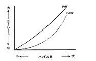
ここで、図12を参照して、ハンドル角速度に応じたハンドル角とヨーレートとの関係について説明する。ここに、図12は、ハンドル角に対するヨーレートの変化特性の模式図である。尚、同図において、図2と重複する箇所には同一の符号を付してその説明を省略する。 Here, with reference to FIG. 12, the relationship between the steering wheel angle according to the steering wheel angular velocity and the yaw rate will be described. FIG. 12 is a schematic diagram of the change characteristic of the yaw rate with respect to the handle angle. In the figure, the same reference numerals are assigned to the same parts as in FIG.
図12において、2本のプロファイルPrH1(実線)及びPrH2(破線)が示される。プロファイルPrH1は、ハンドル角速度が比較的小さい領域におけるヨーレートの変化特性であり、プロファイルPrH2は、ハンドル角速度が比較的大きい領域におけるヨーレートの変化特性である。図12によって明らかなように、ハンドル角速度が大きい場合、車両10のヨー応答が急激なハンドル操作に追従しないため、ヨーレートの変化は大きく遅れる。このような、ヨー応答の遅れを効果的に解消するには、ステアリングギア比を変化させるのが好適である。従って、図11において、ハンドル角速度が大きい領域では、主として、ステアリングギア比可変装置400によるステアリングギア比制御によって、舵の効きが制御されるのである。
In FIG. 12, two profiles PrH1 (solid line) and PrH2 (dashed line) are shown. The profile PrH1 is a yaw rate change characteristic in a region where the steering wheel angular velocity is relatively small, and the profile PrH2 is a yaw rate change characteristic in a region where the steering wheel angular velocity is relatively large. As is apparent from FIG. 12, when the steering wheel angular velocity is large, the yaw response of the vehicle 10 does not follow the abrupt steering operation, so that the change in the yaw rate is greatly delayed. In order to effectively eliminate such a yaw response delay, it is preferable to change the steering gear ratio. Therefore, in FIG. 11, in the region where the steering wheel angular velocity is large, the effectiveness of the rudder is controlled mainly by the steering gear ratio control by the steering gear
ここで、図13を参照して、ハンドル角速度が大きい場合の、ステアリングギア比可変装置400によるステアリングギア比の制御態様について説明する。ここに、図13は、ハンドル角に対するピニオン回転角の変化特性の模式図である。尚、同図において、図8と重複する箇所には同一の符号を付してその説明を省略する。
Here, with reference to FIG. 13, a control mode of the steering gear ratio by the steering gear
図13において、ハンドル角速度が比較的小さい領域におけるピニオン回転角のプロファイルPrI1(実線)が示される。この場合、ハンドル角ST3に対するピニオン回転角はD4である。ここで、ハンドル角速度が比較的大きい場合、ピニオン回転角のプロファイルはPrI2(一点鎖線)のように変更される。ハンドル角が大きくなる側(図示左から右へ向う側)に大きなハンドル角速度でハンドル11が操作される場合、ステアリングギア比可変装置400は、ピニオン回転角を、プロファイルPrI1に相当する値よりも大きくなるように制御する。その結果、ハンドル角ST3におけるピニオン回転角はD5(D5>D4)となる。従って、相対的にステアリングギア比が小さくなって、車両の回頭性が向上し、ハンドル操作にヨー応答が追従し易くなる。一方、ハンドル角速度が小さくなる側(図示、右から左へ向う側)に大きな角速度でハンドル11が操作される場合、ステアリングギア比可変装置400は、ピニオン回転角を、プロファイルPrI1に相当する値よりも小さくなるように制御する。その結果、ハンドル角ST3におけるピニオン回転角はD6(D6<D4)となる。従って、舵角の変化量が相対的に増大し、車両10の旋回状態からの復帰が支援され、車両10は速やかに直進状態に移行することが可能となる。
FIG. 13 shows a profile PrI1 (solid line) of the pinion rotation angle in a region where the steering wheel angular velocity is relatively small. In this case, the pinion rotation angle with respect to the handle angle ST3 is D4. Here, when the steering wheel angular velocity is relatively large, the profile of the pinion rotation angle is changed to PrI2 (one-dot chain line). When the steering wheel 11 is operated at a large steering wheel angular speed on the side on which the steering wheel angle is increased (from the left to the right in the figure), the steering gear
図10に戻り、ステップB10で決定された制御比率でEPS300による操舵トルク制御及びステアリングギア比可変装置400によるステアリングギア比制御が実行されると、処理はステップA10に移行して、一連の処理が繰り返される。
Returning to FIG. 10, when the steering torque control by the
このように、本実施形態に係る操舵特性制御処理によれば、ハンドル角速度に対し舵の効きを一定に維持することが可能となるため、運転者の感性に応じた操舵特性が効果的且つ効率的に実現される。 Thus, according to the steering characteristic control process according to the present embodiment, it is possible to maintain the effectiveness of the rudder constant with respect to the steering wheel angular velocity, and thus the steering characteristic according to the driver's sensitivity is effective and efficient. Is realized.
尚、第1実施形態では車速に応じて、第2実施形態ではハンドル角速度に応じて、夫々制御比率が決定されているが、無論、これらを統合し、その時点の車速及びハンドル角速度に適した制御比率で操舵トルク制御及びステアリングギア比制御を実行してもよい。この場合、一層運転者の感性に適合した操舵特性が実現される。 The control ratios are determined according to the vehicle speed in the first embodiment and according to the steering wheel angular speed in the second embodiment, but of course, these are integrated and suitable for the vehicle speed and steering wheel angular speed at that time. Steering torque control and steering gear ratio control may be executed at a control ratio. In this case, a steering characteristic more suitable for the driver's sensitivity is realized.
本発明は、上述した実施例に限られるものではなく、請求の範囲及び明細書全体から読み取れる発明の要旨或いは思想に反しない範囲で適宜変更可能であり、そのような変更を伴う操舵制御装置もまた本発明の技術的範囲に含まれるものである。 The present invention is not limited to the above-described embodiment, and can be appropriately changed without departing from the spirit or concept of the invention that can be read from the claims and the entire specification. Moreover, it is included in the technical scope of the present invention.
10…車両、100…ECU、200…ヨーレートセンサ、300…EPS、400…ステアリングギア比可変装置、500FL、500FR…車輪速センサ、600…操舵トルクセンサ、700…ハンドル角センサ。 DESCRIPTION OF SYMBOLS 10 ... Vehicle, 100 ... ECU, 200 ... Yaw rate sensor, 300 ... EPS, 400 ... Steering gear ratio variable device, 500FL, 500FR ... Wheel speed sensor, 600 ... Steering torque sensor, 700 ... Steering angle sensor.
Claims (11)
前記操舵トルクに対応する舵の効きの目標値を、所望の前記操舵トルクに対する前記舵の効きの変化特性に合致するように設定する目標値設定手段と、
前記特定された操舵トルクに対応する舵の効きが、前記設定された目標値となるように前記車両の動作条件を制御する制御手段と
を具備することを特徴とする操舵制御装置。 First specifying means for specifying the effectiveness of a rudder that regulates the degree of turning of the vehicle with respect to a steering operation corresponding to the steering torque in the vehicle ;
Target value setting means for setting a target value of the rudder effectiveness corresponding to the steering torque so as to match a change characteristic of the rudder effectiveness with respect to the desired steering torque;
A steering control device comprising: control means for controlling an operating condition of the vehicle so that an effect of a rudder corresponding to the specified steering torque becomes the set target value.
ことを特徴とする請求項1に記載の操舵制御装置。 The target value setting means sets the target value so as to match one change characteristic selected as the desired change characteristic from among a plurality of preset change characteristics. The steering control device according to claim 1.
前記目標値設定手段は、前記目標値を、前記複数のマップの中から前記一の変化特性に対応するものとして選択されたマップに基づいて設定する
ことを特徴とする請求項2に記載の操舵制御装置。 Storage means for storing a plurality of maps set in advance as representing the plurality of change characteristics;
The steering according to claim 2, wherein the target value setting means sets the target value based on a map selected as one corresponding to the one change characteristic from the plurality of maps. Control device.
ことを特徴とする請求項1から3のいずれか一項に記載の操舵制御装置。 The control means controls the operation condition based on a deviation between a rudder effectiveness value corresponding to the identified steering torque and the set target value. The steering control device according to any one of the above.
ことを特徴とする請求項1から4のいずれか一項に記載の操舵制御装置。 The steering control device according to any one of claims 1 to 4, wherein the effectiveness of the rudder is defined as a yaw rate per unit steering wheel angle in the vehicle.
ことを特徴とする請求項1から5のいずれか一項に記載の操舵制御装置。 The control means controls, as the operation condition, at least one of (i) a change characteristic of the vehicle yaw rate with respect to the steering torque and (ii) a change characteristic of the vehicle yaw rate with respect to the steering angle of the vehicle. The steering control device according to claim 1, wherein the steering control device is characterized in that:
ことを特徴とする請求項6に記載の操舵制御装置。 The steering control device according to claim 6, wherein the control unit includes a steering torque control device, and controls a change characteristic of a yaw rate with respect to the steering torque by the steering torque control device.
ことを特徴とする請求項6又は7に記載の操舵制御装置。 The steering control device according to claim 6 or 7, wherein the control means includes a steering gear ratio variable device, and controls a change characteristic of a yaw rate with respect to the steering wheel angle by the steering gear ratio variable device.
ことを特徴とする請求項1から8のいずれか一項に記載の操舵制御装置。 The control means controls, as the operating conditions, (i) a change characteristic of the yaw rate of the vehicle with respect to the steering torque and (ii) a change characteristic of the vehicle yaw rate with respect to a steering angle of the vehicle. The steering control device according to any one of claims 1 to 8.
前記制御手段は、前記特定されるハンドル角速度に応じて、前記各々相互間の相対的な重み付けを行うと共に、該重み付けに従って前記各々を制御する
ことを特徴とする請求項9に記載の操舵制御装置。 A second specifying means for specifying the steering wheel angular velocity of the vehicle;
The steering control device according to claim 9, wherein the control unit performs relative weighting between the respective units according to the specified steering wheel angular velocity, and controls the respective units according to the weighting. .
前記制御手段は、前記特定される速度に応じて、前記各々相互間の相対的な重み付けを行うと共に、該重み付けに従って前記各々を制御する
ことを特徴とする請求項9又は10に記載の操舵制御装置。 Further comprising third specifying means for specifying the speed of the vehicle;
11. The steering control according to claim 9, wherein the control unit performs relative weighting between the respective units according to the specified speed, and controls the respective units according to the weighting. apparatus.
Priority Applications (1)
| Application Number | Priority Date | Filing Date | Title |
|---|---|---|---|
| JP2005223170A JP4222345B2 (en) | 2005-08-01 | 2005-08-01 | Steering control device |
Applications Claiming Priority (1)
| Application Number | Priority Date | Filing Date | Title |
|---|---|---|---|
| JP2005223170A JP4222345B2 (en) | 2005-08-01 | 2005-08-01 | Steering control device |
Publications (2)
| Publication Number | Publication Date |
|---|---|
| JP2007038750A JP2007038750A (en) | 2007-02-15 |
| JP4222345B2 true JP4222345B2 (en) | 2009-02-12 |
Family
ID=37797138
Family Applications (1)
| Application Number | Title | Priority Date | Filing Date |
|---|---|---|---|
| JP2005223170A Expired - Fee Related JP4222345B2 (en) | 2005-08-01 | 2005-08-01 | Steering control device |
Country Status (1)
| Country | Link |
|---|---|
| JP (1) | JP4222345B2 (en) |
Families Citing this family (4)
| Publication number | Priority date | Publication date | Assignee | Title |
|---|---|---|---|---|
| KR100814758B1 (en) | 2007-03-30 | 2008-03-19 | 주식회사 만도 | Method and system for changing variable gear ratio map according to mode change of continuous damping control system |
| JP4539693B2 (en) | 2007-08-27 | 2010-09-08 | トヨタ自動車株式会社 | Steering control device and vehicle |
| JP4470986B2 (en) * | 2007-10-17 | 2010-06-02 | トヨタ自動車株式会社 | Travel control device and vehicle |
| KR101360513B1 (en) | 2012-07-27 | 2014-02-07 | 기아자동차주식회사 | Map choice method of MDPS for friction of steering gear |
-
2005
- 2005-08-01 JP JP2005223170A patent/JP4222345B2/en not_active Expired - Fee Related
Also Published As
| Publication number | Publication date |
|---|---|
| JP2007038750A (en) | 2007-02-15 |
Similar Documents
| Publication | Publication Date | Title |
|---|---|---|
| JP5093295B2 (en) | Steering device and steering control device | |
| US7050896B2 (en) | Control device for vehicle power steering | |
| JP5657996B2 (en) | Momentum control device | |
| US8214107B2 (en) | Vehicle behavior control apparatus and control method | |
| JP2022523577A (en) | Vehicle stabilization system and how it operates | |
| JP4222345B2 (en) | Steering control device | |
| JP2006240496A (en) | Vehicular state-of-motion control device | |
| JP2001191938A (en) | Vehicle steering device | |
| JP2007245901A (en) | Vehicular motion control apparatus | |
| EP1088739B1 (en) | Motor vehicle steering system | |
| JP5117066B2 (en) | Vehicle steering system | |
| JP2008086159A (en) | Electric cart | |
| EP1902916B1 (en) | Steering Variable Gear Ratio (VGR) supporting limit handling driving | |
| KR101297961B1 (en) | Toe control apparatus for active geometry control rear suspension in vehicle and control method thereof | |
| JP2008092682A (en) | Electric cart | |
| JP2006103507A (en) | Vehicle behavior control device | |
| CN112449624A (en) | Steering control device and steering control method | |
| JP2005263031A (en) | Vehicular steering device | |
| JP5289408B2 (en) | Vehicle control device | |
| JP2011057215A (en) | Vehicle controller | |
| JPH08156816A (en) | Yawing momentum control devce for vehicle | |
| JP2006290302A (en) | Vehicle steering device | |
| JP2000203440A (en) | Steering control device | |
| JP4379140B2 (en) | Vehicle steering system | |
| JP2008195350A (en) | Vehicle behavior control device |
Legal Events
| Date | Code | Title | Description |
|---|---|---|---|
| A621 | Written request for application examination |
Free format text: JAPANESE INTERMEDIATE CODE: A621 Effective date: 20070806 |
|
| A977 | Report on retrieval |
Free format text: JAPANESE INTERMEDIATE CODE: A971007 Effective date: 20080519 |
|
| A131 | Notification of reasons for refusal |
Free format text: JAPANESE INTERMEDIATE CODE: A131 Effective date: 20080527 |
|
| A521 | Written amendment |
Free format text: JAPANESE INTERMEDIATE CODE: A523 Effective date: 20080728 |
|
| TRDD | Decision of grant or rejection written | ||
| A01 | Written decision to grant a patent or to grant a registration (utility model) |
Free format text: JAPANESE INTERMEDIATE CODE: A01 Effective date: 20081028 |
|
| A01 | Written decision to grant a patent or to grant a registration (utility model) |
Free format text: JAPANESE INTERMEDIATE CODE: A01 |
|
| A61 | First payment of annual fees (during grant procedure) |
Free format text: JAPANESE INTERMEDIATE CODE: A61 Effective date: 20081110 |
|
| FPAY | Renewal fee payment (prs date is renewal date of database) |
Free format text: PAYMENT UNTIL: 20111128 Year of fee payment: 3 |
|
| FPAY | Renewal fee payment (prs date is renewal date of database) |
Free format text: PAYMENT UNTIL: 20111128 Year of fee payment: 3 |
|
| FPAY | Renewal fee payment (prs date is renewal date of database) |
Free format text: PAYMENT UNTIL: 20121128 Year of fee payment: 4 |
|
| FPAY | Renewal fee payment (prs date is renewal date of database) |
Free format text: PAYMENT UNTIL: 20121128 Year of fee payment: 4 |
|
| FPAY | Renewal fee payment (prs date is renewal date of database) |
Free format text: PAYMENT UNTIL: 20131128 Year of fee payment: 5 |
|
| LAPS | Cancellation because of no payment of annual fees |