JP4219011B2 - Outboard motor air duct device - Google Patents
Outboard motor air duct device Download PDFInfo
- Publication number
- JP4219011B2 JP4219011B2 JP18051398A JP18051398A JP4219011B2 JP 4219011 B2 JP4219011 B2 JP 4219011B2 JP 18051398 A JP18051398 A JP 18051398A JP 18051398 A JP18051398 A JP 18051398A JP 4219011 B2 JP4219011 B2 JP 4219011B2
- Authority
- JP
- Japan
- Prior art keywords
- air duct
- air
- top cowling
- outboard motor
- molding
- Prior art date
- Legal status (The legal status is an assumption and is not a legal conclusion. Google has not performed a legal analysis and makes no representation as to the accuracy of the status listed.)
- Expired - Fee Related
Links
- 238000000465 moulding Methods 0.000 claims description 31
- 230000013011 mating Effects 0.000 claims description 18
- 230000002093 peripheral effect Effects 0.000 claims description 5
- XLYOFNOQVPJJNP-UHFFFAOYSA-N water Substances O XLYOFNOQVPJJNP-UHFFFAOYSA-N 0.000 description 43
- 239000000446 fuel Substances 0.000 description 11
- 230000000694 effects Effects 0.000 description 6
- 238000002347 injection Methods 0.000 description 5
- 239000007924 injection Substances 0.000 description 5
- 238000007789 sealing Methods 0.000 description 5
- 230000003584 silencer Effects 0.000 description 2
- 230000006866 deterioration Effects 0.000 description 1
- 238000007599 discharging Methods 0.000 description 1
- 230000002452 interceptive effect Effects 0.000 description 1
- 238000000034 method Methods 0.000 description 1
- 150000003839 salts Chemical class 0.000 description 1
- 238000000926 separation method Methods 0.000 description 1
Images


Classifications
-
- F—MECHANICAL ENGINEERING; LIGHTING; HEATING; WEAPONS; BLASTING
- F02—COMBUSTION ENGINES; HOT-GAS OR COMBUSTION-PRODUCT ENGINE PLANTS
- F02B—INTERNAL-COMBUSTION PISTON ENGINES; COMBUSTION ENGINES IN GENERAL
- F02B61/00—Adaptations of engines for driving vehicles or for driving propellers; Combinations of engines with gearing
- F02B61/04—Adaptations of engines for driving vehicles or for driving propellers; Combinations of engines with gearing for driving propellers
- F02B61/045—Adaptations of engines for driving vehicles or for driving propellers; Combinations of engines with gearing for driving propellers for marine engines
Landscapes
- Engineering & Computer Science (AREA)
- Ocean & Marine Engineering (AREA)
- Chemical & Material Sciences (AREA)
- Combustion & Propulsion (AREA)
- Mechanical Engineering (AREA)
- General Engineering & Computer Science (AREA)
- Exhaust Silencers (AREA)
Description
【0001】
【発明の属する技術分野】
本発明は、船体の船尾に配設される船外機のエアダクト装置に関する。
【0002】
【従来の技術】
一般的な船外機のエアダクト装置として、従来、例えば、図9〜図11に示す構造のものがある。これは、略水密に形成されたエンジン収納室80aを有するトップカウリング80の後端部に凹部81を凹設するとともに、該凹部81を覆うように蓋状のモールディングエアダクト82を装着し、これによりエンジン収納室80aと画成された膨張室83を形成して構成されている。
【0003】
またモールディングエアダクト82の後壁には上記膨張室83内に外気を導入する4つの外気導入口82aが形成され、上記凹部81の底部には膨張室83内の空気をエジン収納室80a内に取り入れる空気取入れ口85を有する筒状の取入れダクト84が突出形成されている。
【0004】
上記エアダクト装置では、外気導入口82aから導入した空気aを膨張室83内にて空気aと水bとを分離させ、水分離した空気aを空気取入れ口85からエンジン収納室80aに取り入れる。一方、膨張室83内で水分離された水滴bは凹部81の底部に集められてモールディングエアダクト82の下端合面の隙間88から排出される。
【0005】
また雨水や飛沫等がトップカウリング80の上面に付着すると、水滴bはモールディングエアダクト82の上端合面の隙間89から凹部81内に吸い込まれて底部に集められ、上記同様に隙間88から排出される。
【0006】
このようなエアダクト装置においては、エンジンに水分や塩分が吸い込まれるのを防止する観点から、エンジン収納室80a内に侵入する水滴をさらに低減することが要求されている。この水滴を低減するには、第1に膨張室83からエンジン収納室80aに侵入する水滴を低減する、第2にトップカウリング80の外面に付着した雨水等が上記隙間89から膨張室83内に侵入するのを低減するという2つの方法がある。
【0007】
このため、従来では、取入れダクト84を隙間89から離れた位置に配置したり,あるいは空気取入れ口85の開口面積を小さくしたりすることにより、エンジン収納室80a内への水滴の侵入を低減する。また上記外気導入口82aの開口面積を大きくして吸い込み時の空気流速を減少させ、これにより膨張室83内への水滴の吸い込み量を低減する方法が一般的に採用されている。
【0008】
【発明が解決しようとする課題】
しかしながら、上記従来のように、空気取入れ口の開口面積を小さくすると、エンジン収納室への空気の取り込み量が減少し、場合によってエンジンへの吸気量が確保できなくなるおそれがある。
【0009】
また取入れダクトを水滴が侵入する隙間から離す場合には、凹部の大きさの関係から配置位置を設定するのは困難である。
【0010】
さらに上記従来の外気導入口の開口面積を大きくする場合には、デザイン的な自由度が制限されるという問題がある。
【0011】
本発明は、上記従来の状況に鑑みてなされたもので、エンジンへの吸気量の問題や取入れダクトの配置位置の問題を生じることなく、かつ外気導入口のデザイン的な問題を生じることなく、エンジン収納室への水滴の侵入を防止できる船外機のエアダクト装置を提供することを目的としている。
【0012】
【課題を解決するための手段】
請求項1の発明は、略水密に形成されたエンジン収納室を有するトップカウリングに凹部を形成するとともに、該凹部を覆うようにモールディングエアダクトを配設し、該モールディングエアダクトと凹部とで上記エンジン収納室と区分けされた膨張室を形成し、該膨張室に外気を導入する外気導入口を形成するとともに、該膨張室内の空気を上記エンジン収納室内に取り入れる空気取入れ口を形成してなる船外機のエアダクト装置において、上記凹部の周縁であって、上記空気取入れ口から前方および左右側方に離隔した位置に該空気取入れ口の少なくとも前側部分を囲むように凹溝を形成し、該凹溝を、上記凹部の周縁に段落ち形成された段部と、該段部の内周縁に立設されたリブとで構成し、空気取入れ口から離れた位置にて外部に連通させ、上記リブの上縁にシール部材を装着し、該シール部材に上記モールディングエアダクトを当接させたことを特徴としている。
【0013】
請求項2の発明は、請求項1において、上記凹溝が上記トップカウリングと上記モールディングエアダクトとの左, 右合面に連通していることを特徴としている。
【0014】
請求項3の発明は、請求項1又は2において、上記空気取入れ口より高所に位置する凹溝がトップカウリングと上記モールディングエアダクトとの合面の斜面に沿って傾斜していることを特徴としている。
【0016】
【発明の作用効果】
請求項1の発明によれば、膨張室を構成する凹部の周縁に空気取入れ口の前側部分を囲むように凹溝を形成し、該凹溝を空気取入れ口から離れた位置にて外部に連通させたので、トップカウリングの上面に付着した水滴は合面部分から凹溝内に流入し、該凹溝を通って外部に排出されることとなる。これにより外部から水滴が膨張室内に流入するのを阻止でき、もってエンジン収納室への水滴の侵入を防止できる効果がある。
【0017】
またトップカウリングに付着した水滴は凹溝を通って外部に排出されることから、外気導入口から入り込む水の量が低減され、その分だけ外気導入口から膨張室内に吸い込まれる水分の絶対量を低減でき、この点からもエンジン収納室への水滴の侵入を防止できる。
【0018】
これにより空気取入れ口の開口面積を大きくすることが可能となり、エンジンへの吸気量を確保できる。また取入れダクトの配置位置に対する設定を不要にでき、さらには外気導入口の開口面積を小さくすることが可能となり、該外気導入口のデザイン上の自由度を向上できる。
【0019】
また、上記凹溝を凹部の周縁に段落ち形成された段部と、該段部の内周縁に立設されたリブとで構成し、該リブの上縁にシール部材を装着するとともに、該シール部材にモールディングエアダクトを当接させたので、膨張室と凹溝との間を水密にシールすることができ、膨張室内への水滴の侵入を確実に防止できる効果がある。
【0020】
請求項2の発明では、上記凹溝をトップカウリングと上記モールディングエアダクトとの左, 右合面部分に連通したので、凹溝内に流入した水滴は左, 右の合面部分から外部に流れ出ることとなり、水滴の流入量が多い場合にも排出することができる。
【0021】
請求項3の発明では、上記空気取入れ口より高所に位置する凹溝をトップカウリングと上記モールディングエアダクトとの合面の斜面に沿って傾斜させたので、凹溝内に流入した水滴を素早く合面から外部に排出でき、凹溝を空気取入れ口より高所に位置させた場合の膨張室内への侵入を防止できる効果がある。
【0022】
【発明の実施の形態】
以下、本発明の実施の形態を添付図面に基づいて説明する。
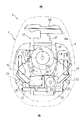
図1ないし図8は、本発明の一実施形態による船外機のエアダクト装置を説明するための図であり、図1〜図3はそれぞれエアダクト装置が配設されたトップカウリングの平面図,側面図、図4はトップカウリング内に収納されたエンジンの平面図、図5〜図7はそれぞれエアダクト装置の膨張室の断面図、図8は船外機の側面図である。
【0023】
図において、1は船外機であり、該船外機1は船体2の船尾2aに固定されたクランプ機構1aにより上下方向に揺動可能に、かつ左右方向に旋回可能に枢支されている。
【0024】
上記船外機1は、推進機3が配設されたロアケース4の上部にロアマウントカバー5を接続し、該ロアマウントカバー5の上部にエプロン6を接続し、さらに該エプロン6の上部にボトムカウリング7aとトップカウリング7bとからなるカウリング7を接続して構成されている。
【0025】
上記カウリング7内には上記推進機3を回転駆動するエンジン10が搭載されており、該エンジン10はボトムカウリング7a,及びトップカウリング7bとで形成された水密なエンジン収納室9内に収納されている。
【0026】
上記エンジン10は、筒内燃料噴射式V型2サイクルエンジンであり、図4に示すように、クランク軸11を航走時に略垂直をなすように縦置きに配置されている。また上記エンジン10は、船体後方にVバンクをなす左, 右のシリンダボアを有するシリンダブロック12と、該シリンダブロック12の後側合面に締結された左, 右のシリンダヘッド13,13と、該シリンダブロック12の前側合面に締結されたクランクケース14とを備えている。なお、15は点火プラグである。
【0027】
上記クランクケース14の前面にはインテークマニホールド16を介在させてスロットルボディ17が接続され、該スロットルボディ17の前面には各気筒共通の中空箱状のサイレンサ18が接続されており、該サイレンサ18には上下方向に延びる空気吸込口18aが形成されている。
【0028】
上記エンジン10には筒内燃料噴射装置が配設されている。この燃料噴射装置は、主として、左, 右のシリンダヘッド13に各気筒ごとに挿着され筒内に燃料を直接噴射するインジェクタ20と、各インジェクタ20に燃料を分配供給するインジェクタレール21と、該インジェクタレール21に加圧した燃料を圧送する燃料ポンプ22とを備えている。
【0029】
上記燃料ポンプ22はVバンク内の上端部に配置され、該ポンプ22の回転軸23にはプーリ24が装着されており、該プーリ24はクランク軸11の上端に装着されたクランクプーリ25にベルト26を介して連結されている。なお、27はフライホイールである。
【0030】
上記船外機1には本実施形態の特徴をなすエアダクト装置が配設されており、該エアダクト装置は以下の構造となっている。
【0031】
上記トップカウリング7bの上壁7cのクランク軸11を挟んだ左, 右側部には船体前後方向に延びる凹部30,30が凹設されている。この各凹部30はトップカウリング7bの上壁7cの後端から前方に延びており、該凹部30の前端30cはクランク軸11より前側に位置している。
【0032】
上記凹部30は内壁30aと底壁30bとからなり、該底壁30bは上記前端30cから後下がりに傾斜する傾斜部31aと、該傾斜部31aに続いて後方に略水平に延びる平坦部31bと、該平坦部31bに続いて段落ちに形成された低部31cとからなり、該低部31cの外縁にはトップカウリング7の外面に連なる斜面31dが形成されている。これにより凹部30内に溜まった水滴は低部31cに集められて斜面31dから外部に排出される。
【0033】
上記トップカウリング7bには蓋状のモールディングエアダクト32が取り外し可能に装着されている。このモールディングエアダクト32はトップカウリング7bの外面と略連続面をなすように形成されており、該モールディングエアダクト32とトップカウリング7bとの合面には全周に渡る若干の隙間33が設けられている。
【0034】
上記モールディングエアダクト32は、上記左, 右の凹部30を覆うとともに、トップカウリング7bの背面を覆う平面視で大略凹形状のものであり、このモールディングエアダクト32と左, 右の凹部30とでそれぞれ分割された第1,第2膨張室35,36が形成されている。
【0035】
上記第1,第2膨張室35,36は、それぞれクランク軸11を挟んだトップカウリング7bの左, 右側部に配置され、トップカウリング7bの後端から前方に延びかつ各膨張室35,36の前端はクランク軸11より前側に位置している。また第1,第2膨張室35,36はそれぞれ独立しており、かつエンジン収納室9と区分けされている。
【0036】
上記モールディングエアダクト32の左, 右下縁の低部31cに対応する部分には切り欠き部32aが切り欠いて形成されており、該切り欠き部31aと上記低部31cとで各膨張室35,36と外部とを連通する外気導入口37が形成されている。
【0037】
また上記左, 右の凹部30の底壁30bには上方に延びる筒状の取入れダクト38が突出形成されており、該取入れダクト38の上面には各膨張室35,36とエンジン収納室9とを連通する空気取入れ口39が形成されている。この取入れダクト39は底部30bの平坦部31bから傾斜部31aの途中に渡って延びる大略長方形状に形成されており、これにより空気取入れ口39の開口面積を大きく設定している。
【0038】
次にエアダクト装置の防水構造について説明する。
上記トップカウリング7b,及びモールディングエアダクト32の外面は後端部を頂面として該後端部から前方,後方にまた左, 右側方に向かってなだらかな斜面となっており、雨水等は各斜面を伝って流れ落ちるようになっている。
【0039】
上記左, 右の凹部30の内壁30aの上縁には前後方向に延びる段部40が段落ち形成されており、この段部40の下縁には第1リブ41が一体に突出形成されている。この第1リブ41と段部40とで第1凹溝42が形成されており、この凹溝42の前半部はトップカウリング7bの斜面に沿って前下がりに傾斜しており、後半部は後下がりに傾斜してモールディングエアダクト32の下端合面の隙間33から外部に連通している。
【0040】
また上記第1リブ41の前端にはこれに続いて取入れダクト38の前方を囲むように湾曲して延びる第2リブ43が一体形成されており、該第2リブ43は底壁30bの外縁まで延びている。この第2リブ43と凹部30の前端部とで上記第1凹溝42に連通する第2凹溝44が形成されている。また第2リブ43には船外機1のチルトアップ時に凹部30内に進入した水を外部に排出する水抜き孔45が形成されている。
【0041】
上記第2リブ43にはこれに続いて底壁30bの外縁に沿って後方に延びる第3リブ46が一体形成されている。この第3リブ46はトップカウリング7bの合面に沿って後下がりに傾斜しており、該第3リブ46の後端は平坦部31bの中央部まで延びている。上記第3リブ46と底壁30bの外縁部30cとで第2凹溝44に連通する第3凹溝47が形成されており、該第3凹溝47は左, 右の外側合面の隙間33から外部に連通している。
【0042】
これにより空気取入れ口39の前半部は第1〜第3凹溝42,44,47により囲まれている。また各凹溝42,44,47は空気取入れ口39より高所に位置しており、トップカウリング7bの合面の斜面に沿って傾斜している。
【0043】
上記各リブ41,43,46の上縁にはゴム等からなるシール部材50が装着されており、該シール部材50にはモールディングエアダクト32の下面が圧接している。これにより第1〜第3凹溝42,44,47と第1,第2膨張室35,36との間は水密にシールされている。
【0044】
次に本実施形態の作用効果について説明する。
図3,図7に示すように、エンジン10が始動すると、左, 右の外気導入口37から外気が第1,第2膨張室35,36に導入され、導入された空気aは各膨張室35,36内にて空気と水とに分離され、水分離された空気aが左, 右の空気取入れ口39からエンジン収納室9内に取り入れられる。この左, 右の空気取入れ口39から入り込んだ空気aはエンジン収納室9内で合流し、サイレンサ18の吸込口18aから吸引されてエンジン10に供給される。一方、各膨張室35,36内で水分離された水滴は底壁30bに落下して低部31cに集められ、斜面31dから外部に排出される。
【0045】
図1,図2に示すように、雨水や飛沫等によりトップカウリング7bの上面部分に水滴bが付着すると、水滴bはトップカウリング7bとモールディングエアダクト32との合面の隙間33から第1凹溝42内に流入し、この水滴bの一部は凹溝42に後半部に沿って流れモールディングエアダクト32の下端合面の隙間33から外部に排出される。残りの水滴bは凹溝42の前半部に沿って流れて第2凹溝44内に流入し、該第2凹溝44を通って第3凹溝47から左, 右合面の隙間33から外部に排出される。
【0046】
このように本実施形態によれば、膨張室を第1,第2膨張室35,36に分割したので、単体の膨張室を小さくすることにより、トップカウリング7bの余剰空間となっている部分に配置することが可能となり、配置レイアウトに対する自由度を向上でき、また容量の増大を図ることが可能となって水分離機能を向上できる。
【0047】
本実施形態では、第1,第2膨張室35,36をクランク軸11を挟んだトップカウリング7bの左, 右側部に配置したので、燃料噴射装置を構成するインジェクタ20,インジェクタレール21,及び燃料ポンプ22等に干渉することなく左, 右にバランス良く配置でき、該燃料噴射装置を搭載した場合の容量不足を補うことができ、よってカウリング7の大型化,及び見栄えの悪化を生じることなく必要容量を確保できる。
【0048】
本実施形態では、上記第1,第2膨張室35,35をトップカウリング7bの後端から前方に延びるように配置し、各膨張室35,36の前端をクランク軸11より前側に位置させたので、トップカウリング7bのクランク軸11周りの余剰空間を有効利用して容量をさらに増大できる。
【0049】
また上記第1,第2膨張室35,36の配置レイアウトに対する自由度を向上できるので、カウリング7内でのエンジン構成部品のレイアウトに対する自由度も向上でき、それだけレイアウト設計を行う際の効率を向上でき、カウリング7全体をコンパクトにできる。
【0050】
なお、上記実施形態では、第1,第2膨張室35,36をトップカウリング7bの上壁7cの左, 右側部に前後方向に延設した場合を説明したが、本発明はこれに限られるものではない。例えば、第1,第2膨張室を船幅方向に、あるいはクランク軸に平行に上下方向に配設してもよく、また第1,第2膨張室をそれぞれ別方向に配設してもよく、要はトップカウリングの余剰空間を利用して配設することにより、上記実施形態と略同様の効果が得られる。
【0051】
本実施形態によれば、凹部30の周縁に空気取入れ口39の前半部を囲むように第1〜第3凹溝42,44,47を形成し、該第1凹溝42の後半部をモールディングエアダクト32の下端合面の隙間33に連通し、第3凹溝47をトップカウリング7bの左, 右合面の隙間33に連通したので、トップカウリング7bに付着した水滴bは上記各凹溝42,44,47を通って外部に排出されることとなり、これにより水滴bが各膨張室35,36内に侵入するのを阻止でき、ひていはエンジン収納室9への水滴の侵入を防止できる。
【0052】
またトップカウリング7bに付着した水滴bのほとんどは各凹溝42,44,47を通って外部に排出されることから、外気導入口37から入り込む水の量を低減でき、該外気導入口37から各膨張室35,36内に吸い込まれる水分の絶対量を低減でき、この点からもエンジン収納室9への水滴の侵入を防止できる。
【0053】
その結果、空気取入れ口39の開口面積を大きくすることが可能となり、エンジンへの吸気量を確保できる。また取入れダクト38の配置位置に対する設定を不要にでき、レイアウト設計を容易にできる。さらに外気導入口37の開口面積を従来に比べて小さくすることが可能となり、外気導入口37のレイアウト,及びデザインの自由度を向上できる。
【0054】
本実施形態では、上記各凹溝42,44,47をトップカウリング7bの左, 右合面の隙間33に連通したので、凹溝42,44,47内に流入した水滴bは左, 右の隙間33から外部に排出されることから、水滴bの流入量が多い場合にも確実に排出することができ、この点からも膨張室35,36内への侵入を防止できる。
【0055】
また上記各凹溝42,44,47をトップカウリング7の合面の斜面に沿って傾斜させたので、該凹溝42,44,47内に流入した水滴bを直ちに外部に排出でき、各凹溝42,44,47を空気取入れ口39より高所に位置させた場合の膨張室35,36内への侵入を確実に防止できる。
【0056】
本実施形態では、第1〜第3リブ41,43,46の上縁にシール部材50を装着し、該シール部材50にモールディングエアダクト32を圧接させたので、各膨張室35,36と凹溝42,44,47との間を水密にシールすることができ、膨張室35,36内への水滴の侵入をより確実に防止できる。
【0057】
なお、上記実施形態では、膨張室を第1,第2膨張室35,36に分割した場合を説明したが、本発明は膨張室を1つ設けた場合にも勿論適用でき、この場合にも上記実施形態と同様の効果が得られる。
【図面の簡単な説明】
【図1】本発明の一実施形態による船外機のエアダクト装置を説明するためのトップカウリングの平面図である。
【図2】上記トップカウリングの側面図である。
【図3】上記トップカウリングの膨張室の拡大側面図である。
【図4】上記トップカウリング内に収納されたエンジンの平面図である。
【図5】上記エアダクト装置の膨張室の断面図である(図1のV-V 線断面図) 。
【図6】上記膨張室の断面図である(図1のVI-VI 線断面図) 。
【図7】上記膨張室の断面図である(図1のVII-VII 線断面図) 。
【図8】上記船外機の側面図である。
【図9】従来のエアダクト装置を示す断面側面図である。
【図10】従来のエアダクト装置の平面図である。
【図11】従来のモールディングエアダクトの背面図である。
【符号の説明】
1 船外機
9 エンジン収納室
10 エンジン
7b トップカウリング
30 凹部
32 モールディングエアダクト
35 第1膨張室
36 第2膨張室
37 外気導入口
39 空気取入れ口
42,44,47 凹溝
40 段部
41,43,46 リブ
50 シール部材[0001]
BACKGROUND OF THE INVENTION
The present invention relates to an air duct device for an outboard motor disposed at the stern of a hull.
[0002]
[Prior art]
2. Description of the Related Art Conventionally, as an outboard motor air duct device, for example, there is one having a structure shown in FIGS. This is because a
[0003]
The rear wall of the
[0004]
In the air duct device, the air a introduced from the
[0005]
When rainwater or splashes adhere to the top surface of the top cowling 80, the water droplet b is sucked into the
[0006]
In such an air duct device, it is required to further reduce water droplets that enter the
[0007]
For this reason, conventionally, the ingress of water droplets into the
[0008]
[Problems to be solved by the invention]
However, if the opening area of the air intake port is reduced as in the conventional case, the amount of air taken into the engine storage chamber is reduced, and there is a possibility that the intake amount to the engine cannot be secured in some cases.
[0009]
In addition, when the intake duct is separated from the gap through which water droplets enter, it is difficult to set the arrangement position because of the size of the recess.
[0010]
Furthermore, when increasing the opening area of the conventional outside air inlet, there is a problem that the degree of freedom in design is limited.
[0011]
The present invention has been made in view of the above-described conventional situation, without causing a problem of the intake air amount to the engine and a problem of the arrangement position of the intake duct, and without causing a design problem of the outside air inlet, An object of the present invention is to provide an air duct device for an outboard motor that can prevent water droplets from entering the engine storage chamber.
[0012]
[Means for Solving the Problems]
According to the first aspect of the present invention, a recess is formed in a top cowling having an engine storage chamber formed in a substantially watertight manner, a molding air duct is disposed so as to cover the recess, and the engine storage is performed by the molding air duct and the recess. An outboard motor formed with an expansion chamber separated from the chamber, forming an outside air introduction port for introducing outside air into the expansion chamber, and forming an air intake port for taking the air in the expansion chamber into the engine storage chamber In the air duct apparatus, a groove is formed at a peripheral edge of the recess and at a position spaced forward and left and right from the air intake port so as to surround at least a front side portion of the air intake port. , with the outside and a stepped portion periphery is stepped formed on the recess, constituted by an inner peripheral edge standing on the ribs of the step portion at a position away from the air inlet Is allowed, the sealing member is attached to the upper edge of the rib is characterized in that is brought into contact with the molding air duct to the seal member.
[0013]
The invention of claim 2 is characterized in that, in claim 1, the concave groove communicates with the left and right mating surfaces of the top cowling and the molding air duct .
[0014]
The invention of claim 3 is characterized in that, in claim 1 or 2, the concave groove located higher than the air intake port is inclined along the slope of the mating surface of the top cowling and the molding air duct. Yes.
[0016]
[Effects of the invention]
According to the first aspect of the present invention, the concave groove is formed on the periphery of the concave portion constituting the expansion chamber so as to surround the front side portion of the air intake port, and the concave groove communicates with the outside at a position away from the air intake port. As a result, water droplets adhering to the upper surface of the top cowling flow into the concave groove from the mating surface portion, and are discharged to the outside through the concave groove. As a result, it is possible to prevent water droplets from flowing into the expansion chamber from the outside, thereby preventing water droplets from entering the engine storage chamber.
[0017]
In addition, since water droplets adhering to the top cowling are discharged to the outside through the recessed groove, the amount of water entering from the outside air introduction port is reduced, and the absolute amount of water sucked into the expansion chamber from the outside air introduction port is reduced accordingly. From this point, water droplets can be prevented from entering the engine storage chamber.
[0018]
As a result, the opening area of the air intake port can be increased, and the intake amount to the engine can be secured. Further, the setting for the arrangement position of the intake duct can be made unnecessary, the opening area of the outside air introduction port can be reduced, and the degree of freedom in designing the outside air introduction port can be improved.
[0019]
Further, the concave groove is composed of a stepped portion formed on the periphery of the recessed portion and a rib standing on the inner periphery of the stepped portion, and a seal member is mounted on the upper edge of the rib, Since the molding air duct is brought into contact with the seal member, the space between the expansion chamber and the concave groove can be sealed in a watertight manner, and there is an effect that water droplets can be reliably prevented from entering the expansion chamber.
[0020]
In the invention of claim 2, since the concave groove communicates with the left and right mating portions of the top cowling and the molding air duct, water droplets flowing into the concave groove flow out to the outside from the left and right mating portions. Thus, it can be discharged even when the inflow of water drops is large.
[0021]
In the invention of claim 3, since the concave groove positioned higher than the air intake port is inclined along the slope of the mating surface between the top cowling and the molding air duct, the water droplets flowing into the concave groove are quickly combined. It can be discharged from the surface to the outside, and has the effect of preventing the intrusion into the expansion chamber when the concave groove is positioned higher than the air intake port.
[0022]
DETAILED DESCRIPTION OF THE INVENTION
Hereinafter, embodiments of the present invention will be described with reference to the accompanying drawings.
FIGS. 1 to 8 are views for explaining an air duct device of an outboard motor according to an embodiment of the present invention. FIGS. 1 to 3 are a plan view and a side view of a top cowling in which the air duct device is disposed, respectively. 4 is a plan view of the engine housed in the top cowling, FIGS. 5 to 7 are sectional views of the expansion chamber of the air duct device, and FIG. 8 is a side view of the outboard motor.
[0023]
In the figure, reference numeral 1 denotes an outboard motor. The outboard motor 1 is pivotally supported by a clamp mechanism 1a fixed to the stern 2a of the hull 2 so as to be able to swing in the vertical direction and to be able to turn in the left-right direction. .
[0024]
The outboard motor 1 has a lower mount cover 5 connected to an upper portion of a lower case 4 in which a propulsion device 3 is disposed, an
[0025]
An
[0026]
The
[0027]
A
[0028]
The
[0029]
The
[0030]
The outboard motor 1 is provided with an air duct device that characterizes the present embodiment, and the air duct device has the following structure.
[0031]
On the left and right sides of the
[0032]
The
[0033]
A lid-shaped
[0034]
The
[0035]
The first and
[0036]
A
[0037]
A
[0038]
Next, the waterproof structure of the air duct device will be described.
The outer surfaces of the
[0039]
A
[0040]
A
[0041]
The
[0042]
As a result, the front half of the
[0043]
A sealing
[0044]
Next, the effect of this embodiment is demonstrated.
As shown in FIGS. 3 and 7, when the
[0045]
As shown in FIGS. 1 and 2, when water droplets b adhere to the upper surface portion of the
[0046]
As described above, according to the present embodiment, the expansion chamber is divided into the first and
[0047]
In the present embodiment, the first and
[0048]
In the present embodiment, the first and
[0049]
In addition, since the degree of freedom with respect to the layout of the first and
[0050]
In the above embodiment, the case where the first and
[0051]
According to the present embodiment, the first to third
[0052]
Further, since most of the water droplets b adhering to the
[0053]
As a result, the opening area of the
[0054]
In the present embodiment, since each of the
[0055]
Further, since each of the
[0056]
In the present embodiment, the sealing
[0057]
In the above embodiment, the case where the expansion chamber is divided into the first and
[Brief description of the drawings]
FIG. 1 is a plan view of a top cowling for explaining an air duct device for an outboard motor according to an embodiment of the present invention.
FIG. 2 is a side view of the top cowling.
FIG. 3 is an enlarged side view of an expansion chamber of the top cowling.
FIG. 4 is a plan view of an engine housed in the top cowling.
FIG. 5 is a cross-sectional view of the expansion chamber of the air duct device (cross-sectional view taken along the line VV in FIG. 1).
6 is a cross-sectional view of the expansion chamber (a cross-sectional view taken along line VI-VI in FIG. 1).
7 is a cross-sectional view of the expansion chamber (a cross-sectional view taken along line VII-VII in FIG. 1).
FIG. 8 is a side view of the outboard motor.
FIG. 9 is a cross-sectional side view showing a conventional air duct device.
FIG. 10 is a plan view of a conventional air duct device.
FIG. 11 is a rear view of a conventional molding air duct.
[Explanation of symbols]
DESCRIPTION OF SYMBOLS 1
Claims (3)
上記凹部の周縁であって、上記空気取入れ口から前方および左右側方に離隔した位置に該空気取入れ口の少なくとも前側部分を囲むように凹溝を形成し、
該凹溝を、上記凹部の周縁に段落ち形成された段部と、該段部の内周縁に立設されたリブとで構成し、空気取入れ口から離れた位置にて外部に連通させ、
上記リブの上縁にシール部材を装着し、該シール部材に上記モールディングエアダクトを当接させた
ことを特徴とする船外機のエアダクト装置。An expansion chamber in which a recess is formed in a top cowling having an engine storage chamber formed substantially watertight, and a molding air duct is disposed so as to cover the recess, and the engine storage chamber is separated by the molding air duct and the recess. In the air duct device for an outboard motor, the outside air introduction port for introducing outside air into the expansion chamber is formed, and the air intake port for taking the air in the expansion chamber into the engine storage chamber is formed.
Forming a concave groove so as to surround at least a front side portion of the air intake port at a position that is a peripheral edge of the concave portion and spaced forward and left and right from the air intake port;
The concave groove is composed of a stepped portion formed on the peripheral edge of the concave portion and a rib standing on the inner peripheral edge of the stepped portion, and is communicated to the outside at a position away from the air intake port.
An air duct device for an outboard motor, wherein a seal member is mounted on an upper edge of the rib, and the molding air duct is brought into contact with the seal member.
Priority Applications (2)
| Application Number | Priority Date | Filing Date | Title |
|---|---|---|---|
| JP18051398A JP4219011B2 (en) | 1998-06-26 | 1998-06-26 | Outboard motor air duct device |
| US09/344,720 US6287161B1 (en) | 1998-06-26 | 1999-06-25 | Cowling for outboard motor |
Applications Claiming Priority (1)
| Application Number | Priority Date | Filing Date | Title |
|---|---|---|---|
| JP18051398A JP4219011B2 (en) | 1998-06-26 | 1998-06-26 | Outboard motor air duct device |
Publications (2)
| Publication Number | Publication Date |
|---|---|
| JP2000016389A JP2000016389A (en) | 2000-01-18 |
| JP4219011B2 true JP4219011B2 (en) | 2009-02-04 |
Family
ID=16084577
Family Applications (1)
| Application Number | Title | Priority Date | Filing Date |
|---|---|---|---|
| JP18051398A Expired - Fee Related JP4219011B2 (en) | 1998-06-26 | 1998-06-26 | Outboard motor air duct device |
Country Status (1)
| Country | Link |
|---|---|
| JP (1) | JP4219011B2 (en) |
Families Citing this family (6)
| Publication number | Priority date | Publication date | Assignee | Title |
|---|---|---|---|---|
| CN100445166C (en) * | 2002-08-22 | 2008-12-24 | 韩国防 | V concave slide plate type motorboat |
| JP4913118B2 (en) | 2008-12-11 | 2012-04-11 | 本田技研工業株式会社 | Outboard motor |
| JP4834060B2 (en) * | 2008-12-12 | 2011-12-07 | 本田技研工業株式会社 | Outboard motor |
| US8371885B2 (en) | 2008-12-12 | 2013-02-12 | Honda Motor Co., Ltd | Outboard motor |
| JP4834061B2 (en) * | 2008-12-12 | 2011-12-07 | 本田技研工業株式会社 | Outboard motor |
| US8328590B2 (en) | 2008-12-12 | 2012-12-11 | Honda Motor Co., Ltd. | Outboard motor |
-
1998
- 1998-06-26 JP JP18051398A patent/JP4219011B2/en not_active Expired - Fee Related
Also Published As
| Publication number | Publication date |
|---|---|
| JP2000016389A (en) | 2000-01-18 |
Similar Documents
| Publication | Publication Date | Title |
|---|---|---|
| US4887692A (en) | Noise reducing device for marine propulsion | |
| JPH09301286A (en) | Oil filter arrangement structure for water vehicle | |
| JP3765606B2 (en) | Water vehicle cooling system | |
| US7210562B2 (en) | Oil pan structure for four-cycle engine | |
| JP3907082B2 (en) | Outboard motor | |
| JP3141089B2 (en) | Temperature control device for water-cooled internal combustion engine | |
| JP4219011B2 (en) | Outboard motor air duct device | |
| US6132273A (en) | Cowling for outboard motor | |
| JP2001214722A (en) | Oil passage structure of engine for small-sized ship | |
| JP2002031002A (en) | Air guide device in cowling of outboard motor | |
| US6681750B2 (en) | Blow-by gas ventilation system for engine | |
| US7021979B2 (en) | Outboard motor | |
| US7247065B2 (en) | Outboard motor | |
| JP4070882B2 (en) | Outboard motor air duct device | |
| JPH02197496A (en) | Air intake device for outboard engine | |
| JP4446303B2 (en) | Outboard motor | |
| US20040069287A1 (en) | Oil separator for engine, and personal watercraft | |
| JP2002138912A (en) | Outboard motor | |
| JP4269027B2 (en) | Outboard motor intake system | |
| JP2003172116A (en) | Oil tank structure for small vessel | |
| JP4112731B2 (en) | Water motorcycle | |
| JP4343392B2 (en) | Intake structure of small planing boat engine | |
| JP4269026B2 (en) | Outboard motor intake system | |
| JP4607640B2 (en) | Aircraft intake system | |
| JP4253208B2 (en) | Small planing boat |
Legal Events
| Date | Code | Title | Description |
|---|---|---|---|
| A621 | Written request for application examination |
Free format text: JAPANESE INTERMEDIATE CODE: A621 Effective date: 20050426 |
|
| A977 | Report on retrieval |
Free format text: JAPANESE INTERMEDIATE CODE: A971007 Effective date: 20070921 |
|
| A131 | Notification of reasons for refusal |
Free format text: JAPANESE INTERMEDIATE CODE: A131 Effective date: 20071002 |
|
| A521 | Written amendment |
Free format text: JAPANESE INTERMEDIATE CODE: A523 Effective date: 20071130 |
|
| A131 | Notification of reasons for refusal |
Free format text: JAPANESE INTERMEDIATE CODE: A131 Effective date: 20080805 |
|
| A521 | Written amendment |
Free format text: JAPANESE INTERMEDIATE CODE: A523 Effective date: 20080930 |
|
| TRDD | Decision of grant or rejection written | ||
| A01 | Written decision to grant a patent or to grant a registration (utility model) |
Free format text: JAPANESE INTERMEDIATE CODE: A01 Effective date: 20081111 |
|
| A01 | Written decision to grant a patent or to grant a registration (utility model) |
Free format text: JAPANESE INTERMEDIATE CODE: A01 |
|
| A61 | First payment of annual fees (during grant procedure) |
Free format text: JAPANESE INTERMEDIATE CODE: A61 Effective date: 20081111 |
|
| FPAY | Renewal fee payment (prs date is renewal date of database) |
Free format text: PAYMENT UNTIL: 20111121 Year of fee payment: 3 |
|
| R150 | Certificate of patent (=grant) or registration of utility model |
Free format text: JAPANESE INTERMEDIATE CODE: R150 |
|
| FPAY | Renewal fee payment (prs date is renewal date of database) |
Free format text: PAYMENT UNTIL: 20111121 Year of fee payment: 3 |
|
| S111 | Request for change of ownership or part of ownership |
Free format text: JAPANESE INTERMEDIATE CODE: R313111 |
|
| FPAY | Renewal fee payment (prs date is renewal date of database) |
Free format text: PAYMENT UNTIL: 20111121 Year of fee payment: 3 |
|
| R371 | Transfer withdrawn |
Free format text: JAPANESE INTERMEDIATE CODE: R371 |
|
| S111 | Request for change of ownership or part of ownership |
Free format text: JAPANESE INTERMEDIATE CODE: R313111 |
|
| FPAY | Renewal fee payment (prs date is renewal date of database) |
Free format text: PAYMENT UNTIL: 20111121 Year of fee payment: 3 |
|
| R350 | Written notification of registration of transfer |
Free format text: JAPANESE INTERMEDIATE CODE: R350 |
|
| LAPS | Cancellation because of no payment of annual fees |