JP4216577B2 - Light guide plate - Google Patents
Light guide plate Download PDFInfo
- Publication number
- JP4216577B2 JP4216577B2 JP2002369364A JP2002369364A JP4216577B2 JP 4216577 B2 JP4216577 B2 JP 4216577B2 JP 2002369364 A JP2002369364 A JP 2002369364A JP 2002369364 A JP2002369364 A JP 2002369364A JP 4216577 B2 JP4216577 B2 JP 4216577B2
- Authority
- JP
- Japan
- Prior art keywords
- light
- light guide
- guide plate
- main body
- receiving surface
- Prior art date
- Legal status (The legal status is an assumption and is not a legal conclusion. Google has not performed a legal analysis and makes no representation as to the accuracy of the status listed.)
- Expired - Fee Related
Links
- 238000000149 argon plasma sintering Methods 0.000 claims description 14
- 230000007423 decrease Effects 0.000 claims description 7
- 229920000139 polyethylene terephthalate Polymers 0.000 claims description 3
- 239000005020 polyethylene terephthalate Substances 0.000 claims description 3
- 239000004642 Polyimide Substances 0.000 claims description 2
- -1 polyethylene terephthalate Polymers 0.000 claims description 2
- 229920001721 polyimide Polymers 0.000 claims description 2
- 229920001296 polysiloxane Polymers 0.000 claims description 2
- 239000004973 liquid crystal related substance Substances 0.000 description 17
- 238000009792 diffusion process Methods 0.000 description 6
- 230000000694 effects Effects 0.000 description 6
- 239000000758 substrate Substances 0.000 description 5
- 230000000644 propagated effect Effects 0.000 description 2
- NIXOWILDQLNWCW-UHFFFAOYSA-N acrylic acid group Chemical group C(C=C)(=O)O NIXOWILDQLNWCW-UHFFFAOYSA-N 0.000 description 1
- 230000015572 biosynthetic process Effects 0.000 description 1
- 239000003795 chemical substances by application Substances 0.000 description 1
- 230000003247 decreasing effect Effects 0.000 description 1
- 239000003822 epoxy resin Substances 0.000 description 1
- 239000011521 glass Substances 0.000 description 1
- 238000005286 illumination Methods 0.000 description 1
- 238000004519 manufacturing process Methods 0.000 description 1
- 239000000463 material Substances 0.000 description 1
- 238000000034 method Methods 0.000 description 1
- 239000003973 paint Substances 0.000 description 1
- 238000007747 plating Methods 0.000 description 1
- 229920000647 polyepoxide Polymers 0.000 description 1
- 230000003014 reinforcing effect Effects 0.000 description 1
- 229920005989 resin Polymers 0.000 description 1
- 239000011347 resin Substances 0.000 description 1
Images


Classifications
-
- G—PHYSICS
- G02—OPTICS
- G02B—OPTICAL ELEMENTS, SYSTEMS OR APPARATUS
- G02B6/00—Light guides; Structural details of arrangements comprising light guides and other optical elements, e.g. couplings
- G02B6/0001—Light guides; Structural details of arrangements comprising light guides and other optical elements, e.g. couplings specially adapted for lighting devices or systems
- G02B6/0011—Light guides; Structural details of arrangements comprising light guides and other optical elements, e.g. couplings specially adapted for lighting devices or systems the light guides being planar or of plate-like form
- G02B6/0013—Means for improving the coupling-in of light from the light source into the light guide
- G02B6/0015—Means for improving the coupling-in of light from the light source into the light guide provided on the surface of the light guide or in the bulk of it
- G02B6/002—Means for improving the coupling-in of light from the light source into the light guide provided on the surface of the light guide or in the bulk of it by shaping at least a portion of the light guide, e.g. with collimating, focussing or diverging surfaces
-
- G—PHYSICS
- G02—OPTICS
- G02B—OPTICAL ELEMENTS, SYSTEMS OR APPARATUS
- G02B6/00—Light guides; Structural details of arrangements comprising light guides and other optical elements, e.g. couplings
- G02B6/0001—Light guides; Structural details of arrangements comprising light guides and other optical elements, e.g. couplings specially adapted for lighting devices or systems
- G02B6/0011—Light guides; Structural details of arrangements comprising light guides and other optical elements, e.g. couplings specially adapted for lighting devices or systems the light guides being planar or of plate-like form
- G02B6/0033—Means for improving the coupling-out of light from the light guide
- G02B6/0035—Means for improving the coupling-out of light from the light guide provided on the surface of the light guide or in the bulk of it
- G02B6/0036—2-D arrangement of prisms, protrusions, indentations or roughened surfaces
-
- G—PHYSICS
- G02—OPTICS
- G02B—OPTICAL ELEMENTS, SYSTEMS OR APPARATUS
- G02B6/00—Light guides; Structural details of arrangements comprising light guides and other optical elements, e.g. couplings
- G02B6/0001—Light guides; Structural details of arrangements comprising light guides and other optical elements, e.g. couplings specially adapted for lighting devices or systems
- G02B6/0011—Light guides; Structural details of arrangements comprising light guides and other optical elements, e.g. couplings specially adapted for lighting devices or systems the light guides being planar or of plate-like form
- G02B6/0033—Means for improving the coupling-out of light from the light guide
- G02B6/0035—Means for improving the coupling-out of light from the light guide provided on the surface of the light guide or in the bulk of it
- G02B6/0038—Linear indentations or grooves, e.g. arc-shaped grooves or meandering grooves, extending over the full length or width of the light guide
-
- G—PHYSICS
- G02—OPTICS
- G02B—OPTICAL ELEMENTS, SYSTEMS OR APPARATUS
- G02B6/00—Light guides; Structural details of arrangements comprising light guides and other optical elements, e.g. couplings
- G02B6/0001—Light guides; Structural details of arrangements comprising light guides and other optical elements, e.g. couplings specially adapted for lighting devices or systems
- G02B6/0011—Light guides; Structural details of arrangements comprising light guides and other optical elements, e.g. couplings specially adapted for lighting devices or systems the light guides being planar or of plate-like form
- G02B6/0033—Means for improving the coupling-out of light from the light guide
- G02B6/0058—Means for improving the coupling-out of light from the light guide varying in density, size, shape or depth along the light guide
- G02B6/0061—Means for improving the coupling-out of light from the light guide varying in density, size, shape or depth along the light guide to provide homogeneous light output intensity
Landscapes
- Physics & Mathematics (AREA)
- General Physics & Mathematics (AREA)
- Optics & Photonics (AREA)
- Planar Illumination Modules (AREA)
- Light Guides In General And Applications Therefor (AREA)
- Led Device Packages (AREA)
Description
【0001】
【発明の属する技術分野】
本発明は、携帯電話や携帯情報端末等に備える液晶パネル面を照明する導光板に関するものである。
【0002】
【従来の技術】
従来、液晶等の表示装置にあっては、表示部を明るく照明するためのバックライト装置が使用されている。このバックライト装置は、表示部である液晶パネルの背面に配置される導光板と、この導光板の側方に配置される発光素子(LED)や冷陰極管等の光源とによって構成されている。このような構成からなるバックライト装置は、導光板の側面から光を入射させるため、導光板の厚み方向に光源を配置しなくてよいので、装置全体を薄型化することができる。ただし、導光板のような薄い部材の側方から光を取り込む構造であるため、受光効率があまり良好ではない。このような問題を改善するために、光源自体の発光強度を高めるか、光源を導光板に近接して配置するといった方法がとられる。また、特許文献1に示すように、光源と導光板の側面との間に集光レンズを配置し、光源から発せられる光を効率よく導光板内に導かせるような提案もなされている。
【0003】
【特許文献1】
特開平7−114024号公報
【0004】
【発明が解決しようとする課題】
しかしながら、前記特許文献1に示されるようなバックライト構造にあっては、集光用のレンズを別途配置しなければならないため、部品点数の増加によってコストが嵩むと共に、レンズの形状や配置の調整による製造工数も増加するといった問題があった。このようなことから、導光板及びバックライト装置全体の薄型化が制限されていた。また、導光板の側方から光を入射した場合に、光源に近い箇所は輝度が高く、遠くなるほど輝度が低下するため輝度ムラが発生するといった問題もあった。
【0005】
また、従来の導光板は、アクリル板を使用した硬質部材で形成されているため、平板形状が一般的であるが、これでは曲面部を有する表示装置に対して均一に照射できないといった問題がある。
【0006】
そこで、本発明の目的は、曲面部を有する液晶等の表示体に面して自由に変形して配設することができると共に、薄型化した場合にも受光及び発光効率を高めることができる導光板を提供することである。
【0007】
【課題を解決するための手段】
上記課題を解決するために、本発明の請求項1に係る導光板は、光源から発する光を側面に受けて面状発光させ、この発光によって表示体を照明する導光板において、前記導光板が前記表示体に沿って曲面状に形成された薄い可撓性部材からなる導光本体部と、この導光本体部の一側面に設けられ前記光源に向かって漸次厚みを持たせて形成された受光部とを備え、この受光部が前記光源から発せられる光を受ける導光本体部の側面の一部を厚くした受光面と、この受光面から前記導光本体部に向けて断面の厚みが次第に減少すると共に、導光本体部の表面及び裏面に向けて前記受光面から円錐状に絞り込まれた導光部とで一体に形成されていることを特徴とする。
【0008】
この発明によれば、導光本体部が曲面形成されている表示体に合わせて薄い可撓性部材で曲面状に形成される一方、導光本体部の側面の一部に厚肉状の受光部を設けているので、光源から放射される光を漏れなく取り込むと共に、効率よく導光本体部に導くことができる。したがって、前記導光本体部を薄く形成した場合にも受光量を低下させることがない。また、前記受光部においては、光源から発せられる光を漏れなく受光可能な受光面と、この受光面から導光本体部内に向けて厚みが次第に減少するように傾斜した導光部を備えた構造になっているので、前記受光部で受けた光を導光部によって滑らかに導光本体部内に拡散させることができる。
【0009】
また、請求項2に係る導光板は、光源から発する光を側面に受けて面状発光させ、この発光によって表示体を照明する導光板において、前記導光板が前記表示体に沿って曲面状に形成された薄い可撓性部材からなる導光本体部と、この導光本体部の一側面に設けられ前記光源に向かって漸次厚みを持たせて形成された受光部とを備え、この受光部が前記光源から発せられる光を受ける導光本体部の側面の一部を厚くした受光面と、この受光面から前記導光本体部に向けて断面の厚みが次第に減少すると共に、導光本体部の表面及び裏面に向けて前記受光面から放射状に広がるように形成された導光部とで一体に形成されていることを特徴とする。
【0010】
この発明によれば、導光部全体の厚み及び表面積を大きくとることができる。このため、受光面から入射させた光を導光本体部に向けて広く拡散させることができる。また、導光部の底部が受光面と平行になっているので、前記受光面に入射した光を幅広く導光本体部に向けて伝播させることができる。
【0012】
前記受光面に切り込み部を設けることで、光源から発せられた光を様々な方向や角度に反射又は屈折させながら導光本体部内に入射させることができる。また、前記受光部近傍での光反射や屈折効果は、導光部に開設する貫通孔によっても可能である。このような切り込み部や貫通孔を設けることで、導光板全体の輝度アップが図られる。
【0013】
また、曲面部を有する表示体に沿って配設される導光本体部の表面に光散乱部を設けたことで、光量が足りない箇所や特に明るく発光させたい箇所を光の屈折や反射によって部分的に強調させることができる。また、前記光散乱部を導光本体部上の光源から遠ざかるにしたがって漸次その配設密度を高めるようにすることで、光源からの距離による輝度バラツキを均一化することができる。
【0014】
また、前記光散乱部の形状が凸面、凹面あるいは貫通孔等から選択することができ、液晶等の表示体の種類や形状に応じた光の反射あるいは屈折効果を得ることができる。さらに、前記光散乱部のサイズや形成位置、配置密度を適宜設定することで、液晶等の表示体に合わせた照明効果が得られる。
【0018】
【発明の実施の形態】
以下、添付図面に基づいて本発明に係る導光板の実施形態を詳細に説明する。
【0019】
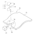
図1は、本発明の第1実施形態に係る導光板22を備えた表示装置21の構成を示したものである。この表示装置21は、表示体である液晶パネル23と、この液晶パネル23の背面に配置される導光板22と、この導光板22の一側面に近接して配置される光源(LED24)とを備えている。
【0020】
前記液晶パネル23は、搭載する電子機器の形状に合わせて曲面形成されており、それに合わせて導光板22も曲面状に形成されている。この導光板22は、厚みが0.1mm程度の透明若しくは半透明のポリエチレンテレフタレート(PET)、シリコーン又はポリイミドのような可撓性を備えたシート部材で形成されており、自由な形状に折曲げが可能となっている。また、導光板22の表面には、液晶パネル23に向けて光を散乱させるための光散乱部30が複数形成されている。
【0021】
このような構成からなる表示装置21にあっては、点状光源であるLED24の発光面29から照射される光を導光板22の一側面に備える受光部26で受けて、導光板22全体を面状に発光させて液晶パネル23を照明する。その際、前記導光板22が変形可能となっているので、液晶パネル23の裏面に密着させて配設することができる。さらに、前記導光板22の表面に光散乱部30が形成されているので、前記LED24の光量不足、受光漏れあるいはLED24からの距離による減衰を補強して輝度アップを図ることができ、これによって、液晶パネル23を明るく照明させることができる。また、導光板22の受光面26を除いた側面及び裏面に白色塗料やメッキ等による光反射部材を設けることで、液晶パネル23への照射効率を高めて全体的な輝度アップを図ることができる。
【0022】
前記光散乱部30は、図2に示すように、前記導光板22の表面に直接加工を施した凹部30a(a),凸部30b(b),微細な溝部30c(c)や、(d)に示すように、導光板22の表面に光拡散剤が混入された光拡散シート30dを貼着して形成される。また、(e)に示すように導光板22に貫通孔30eを設け、この貫通孔30eでの光の屈折あるいは反射を利用して部分的に輝度を高めるといったことが可能である。前記図1では一つの光散乱部30を円形パターンで形成したが、図3(a)に示すように、LED24に対向した直線パターンや図3(b)に示すようなチェックパターンで形成してもよい。また、前記光散乱部30の大きさ及び配置は、LED24から遠ざかるにしたがって大きく、また、配置間隔を詰めることで、液晶パネル23に対する輝度の均一化を図ることができる。
【0023】
図4及び図5は本発明の第2実施形態に係る導光板32を備えた表示装置31の構成を示したものである。この実施形態の導光板32は、一枚の薄い導光本体部25の一側面にLED24からの光を受ける肉厚の受光部26が一体形成されたものである。
【0024】
前記受光部26は、LED24からの光を受ける受光面27と、この受光面27から前記導光本体部25の表面及び裏面の中心に向けてテーパ状に絞り込まれた導光部28とで一体形成されている。なお、前記受光面27の厚みは、LED24の大きさによって適宜設定されるが、前記導光本体部25の厚みが0.1mmの場合は、受光面27の厚みを0.3mm以上に設定するのが好ましい。
【0025】
図5に示したように、前記導光板32は、受光面27の中心がLED24の発光面29の中心と略一致するように設置される。そして、前記LED24の発光面29から放射された光は、受光面27に照射され、円錐状に絞り込まれた導光部28を経て導光本体部25内に拡散される。このように、導光本体部25の側面にLED24の発光面29と略同じ面積を有する受光面27を備えたことによって、LED24で発光した光を漏れなく入射させることができる。したがって、導光本体部25を薄く形成した場合でも、光量を低下させることなくその表面を均一且つ明るく発光させることが可能となった。
【0026】
前記導光板32は、単一のLED24を使用する場合の構成例であるが、バックライト用の光源の種類や形状あるいは使用形態に応じて様々な形態を取り得る。以下、図6乃至図8に他の実施形態における導光板について説明する。図6は第3実施形態の導光板42を示したものである。図に示されるように、この導光板42の受光部46は、受光面47の形状が前記導光板32の受光面37と同一の円形であり、導光部48を前記受光面47から放射状に広がるように導光本体部45に向けて形成してある。受光部46がこのような形状をとることで、前記導光板32の受光部36に比べて導光部48の厚み及び表面積を大きくとることができる。このため、前記受光面47から入射させた光を導光本体部45に向けて広く拡散させることができる。また、導光部48の底部が受光面47と平行になっているので、前記受光面47に入射した光を幅広く導光本体部45に向けて伝播させることができる。
【0027】
また、図7に示した第4実施形態の導光板52の受光部56は、受光面57を横方向に長く形成した楕円形状をしており、導光部58を前記受光面57から放射状に広がるように導光本体部55に向けてテーパ状に形成されている。この導光板52によれば、受光面57が横方向に広くなっているので、比較的サイズの大きなLEDを配設した場合でも光を漏らさず有効に導光本体部55に拡散させることができる。
【0028】
また、図8に示した第5実施形態の導光板62の受光部66は、受光面67が導光本体部65の側面全体を均等に厚くした長方形状となっており、また、導光部68が前記受光面67から導光本体部65の厚みに絞り込まれるようになだらかに傾斜している。このように前記受光面67が導光本体部65の側面全体に亘って形成されているので、LEDを前記受光面67に沿って複数配設したり、LEDの代わりに棒状の蛍光管を配設するといった使用方法が可能であり、光量を多く取り入れる場合に適している。前記複数のLEDや棒状の蛍光管等を使用して均等且つ平行に受光面67に入光した場合は、そのまま導光部68を通過して導光本体部65に拡散される。このため、導光本体部65をムラなく均等に照明することができる。
【0029】
次に、前記第2実施形態乃至第5実施形態に示したような肉厚の受光部を備えた導光板において、さらに受光部における光拡散効果を図った導光板の実施形態を図9及び図10に示す。図9は第6実施形態の導光板72を示したものであり、LED24からの光を受ける受光部76をV字状に切削して形成したものである。このように切削することで、受光面77が広がると共に、LED24からの入射角を変化させることができるので、導光本体部75の光拡散効果も高めることができる。図10は第7実施形態の導光板82を示したものである。この導光板82は、受光部86を構成する導光部88に貫通孔89を設けたものである。このような貫通孔89を設けたことによって、受光面87で受けた光が前記貫通孔89の内壁面で反射あるいは屈折して導光本体部85に拡散させることができる。
【0030】
なお、前記第2実施形態乃至第7実施形態に示した導光板に第1実施形態で示した導光板22のように光拡散部30を形成することで、部分的に発光強度を高めたり、弱めたりすることができる。
【0031】
次に、前述した各実施形態における導光板と、この導光板をパッケージ内に支持するための支持部材とを備えた導光板支持ユニットについて説明する。図11は前記第1実施形態の導光板22と、この導光板22を支持する支持部材91からなる導光板支持ユニットの組み合わせ例を示したものである。支持部材91は、LED24を実装する基板92と、この基板92上に突出して設けられ、導光板22を挟持する挟持部93とで構成されている。前記基板92はガラスエポキシ樹脂からなり、LED24を実装するための一対の電極パターン(図示せず)が正面から左右側面及び背面の一部にかけて形成されている。一方、挟持部93は透明な樹脂材でコ字状に形成され、前記基板92上に一体形成される。前記挟持部93は、基板92に実装されたLED24の発光方向に延びる一対の挟持板94a,94bを備え、前記導光板22が差し込み可能な間隔に設定されている。また、図11(b)に示したように、前記挟持部93の上面及び下面に光の拡散を抑える遮光部材96を配設することによって、LED24から発せられる光を導光板22の側面に対して集中的に照射させることができる。
【0032】
前記構成からなる支持部材91にあっては、LED24を中心に一対の挟持板94a,94bが固定されているため、この挟持板94a,94b間に導光板22を差し込むだけでLED24の発光中心を導光板22の側面の受光面に合わせることができる。図12は側面に光拡散用のV字状の切り欠き部95が形成された導光板102を前記支持部材91に装着したものである。このように前記支持部材91を用いることで、光拡散用の加工を施した受光面とLED24とを簡易且つ正確に位置合わせを行うことができる。また、前記支持部材91では、導光板全体を片持ち支持する構造であると共に、その支持部分が発光するため、導光面を広くとることができる。
【0033】
【発明の効果】
以上説明したように、本発明に係る導光板によれば、この導光板が可撓性を備えた薄いシート部材で形成されているので、面状に発光させる導光本体部を液晶パネルなどの表示体の形状に合わせて湾曲させたり、折曲げたりすることが可能である。このため、前記表示体に密着させて均一に照明することができる。また、前記導光板の側面に厚みのある受光部を設けることによって、前記導光本体部を薄型化した場合にも受光効率の低下を抑えることができる。
【0034】
また、前記表示体に面して配設される導光本体部の表面に凹凸部や光拡散部材を部分的に設けることで、光源からの距離による光量の低下を補完して導光板全体の輝度を均一化させることができる。
【0035】
また、前記導光板の一端を片持ち支持する挟持部及び光源とが一体形成された支持部材を備えたことで、薄型の導光板を安定して支持することができると共に、光源との位置決め作業が容易となる。
【図面の簡単な説明】
【図1】本発明に係る第1実施形態の導光板を備えた表示装置の分解斜視図である。
【図2】上記導光板に設ける光散乱部の各種形態を示す断面図である。
【図3】上記光散乱部の配置例を示す平面図である。
【図4】本発明に係る第2実施形態の導光板を備えた表示装置の分解斜視図である。
【図5】上記図4の表示装置の断面図である。
【図6】本発明に係る第3実施形態の導光板の斜視図である。
【図7】本発明に係る第4実施形態の導光板の斜視図である。
【図8】本発明に係る第5実施形態の導光板の斜視図である。
【図9】本発明に係る第6実施形態の導光板の斜視図である。
【図10】本発明に係る第7実施形態の導光板の斜視図である。
【図11】導光板及び支持部材からなる導光板支持ユニットの斜視図及び断面図である。
【図12】受光面に切り欠き部が形成された導光板と支持部材からなる導光板支持ユニットの斜視図である。
【符号の説明】
21,31 表示装置
22,32,42,52,62,72,82 導光板
23 液晶パネル(表示体)
24 LED(光源)
25,35,45,55,65,75,85 導光本体部
26,36,46,56,66,76,86 受光部
28,38,48,58,68,78,88 導光部
30 光散乱部[0001]
BACKGROUND OF THE INVENTION
The present invention relates to a light guide plate to illuminate the liquid crystal panel surface comprising a mobile phone and a portable information terminal, and the like.
[0002]
[Prior art]
Conventionally, in a display device such as a liquid crystal display, a backlight device for brightly illuminating a display unit is used. This backlight device includes a light guide plate disposed on the back surface of a liquid crystal panel as a display unit, and a light source such as a light emitting element (LED) or a cold cathode tube disposed on the side of the light guide plate. . In the backlight device having such a configuration, since light is incident from the side surface of the light guide plate, it is not necessary to arrange a light source in the thickness direction of the light guide plate, so that the entire device can be thinned. However, the light receiving efficiency is not so good because the light is taken in from the side of a thin member such as a light guide plate. In order to improve such a problem, a method of increasing the light emission intensity of the light source itself or arranging the light source close to the light guide plate is taken. Also, as shown in Patent Document 1, a proposal has been made to arrange a condensing lens between a light source and a side surface of a light guide plate to efficiently guide light emitted from the light source into the light guide plate.
[0003]
[Patent Document 1]
Japanese Patent Laid-Open No. 7-114024
[Problems to be solved by the invention]
However, in the backlight structure as shown in Patent Document 1, since a condensing lens must be separately arranged, the cost increases due to an increase in the number of parts, and adjustment of the shape and arrangement of the lens There was a problem that the number of manufacturing man-hours increased. For this reason, thinning of the entire light guide plate and backlight device has been limited. In addition, when light is incident from the side of the light guide plate, there is a problem in that brightness is high at a location close to the light source, and brightness decreases as the distance increases.
[0005]
In addition, since the conventional light guide plate is formed of a hard member using an acrylic plate, a flat plate shape is generally used, but there is a problem in that it cannot uniformly irradiate a display device having a curved surface portion. .
[0006]
Accordingly, an object of the present invention is to introduce a liquid crystal display device that can be freely deformed and arranged to face a display body such as a liquid crystal having a curved surface portion, and can improve the light receiving and light emission efficiency even when it is thinned. It is to provide a light plate .
[0007]
[Means for Solving the Problems]
In order to solve the above-described problem, a light guide plate according to claim 1 of the present invention is a light guide plate that receives light emitted from a light source on a side surface and emits light in a planar manner, and illuminates a display body by the light emission. and the light guide body portion comprising a thin flexible member formed into a curved shape along the display body, which is formed by gradually slightly thickened toward the light source provided on one side surface of the light guide body portion A light- receiving surface, and a light-receiving surface in which a part of the side surface of the light guide body that receives light emitted from the light source is thickened, and a cross-sectional thickness from the light-receiving surface toward the light-guide body While gradually decreasing , the light guide body is formed integrally with the light guide section that is narrowed down conically from the light receiving surface toward the front and back surfaces of the light guide main body section .
[0008]
According to the present invention, the light guide main body is formed into a curved surface with a thin flexible member in accordance with the curved display body, while the light receiving main body is thickly received on a part of the side surface of the light guide main body. Since the portion is provided, the light emitted from the light source can be taken in without leakage and can be efficiently guided to the light guide main body portion. Therefore, even when the light guide main body is formed thin, the amount of received light is not reduced. Further, the light receiving portion includes a light receiving surface capable of receiving light emitted from the light source without omission and a light guide portion inclined so that the thickness gradually decreases from the light receiving surface toward the light guide main body portion. Therefore, the light received by the light receiving unit can be smoothly diffused into the light guide main body by the light guide unit.
[0009]
According to a second aspect of the present invention, in the light guide plate that receives light emitted from the light source on the side surface and emits light in a planar shape and illuminates the display body by the light emission, the light guide plate has a curved shape along the display body. A light guide main body formed of a thin flexible member, and a light receiving portion provided on one side surface of the light guide main body and formed gradually with increasing thickness toward the light source. A light-receiving surface having a thickened part of the side surface of the light guide main body that receives light emitted from the light source, and the thickness of the cross section gradually decreases from the light receiving surface toward the light guide main body. It is integrally formed with the light guide part formed so that it may spread radially from the said light-receiving surface toward the front surface and back surface.
[0010]
According to this invention, the thickness and surface area of the entire light guide section can be increased. For this reason, the light incident from the light receiving surface can be diffused widely toward the light guide main body. Moreover, since the bottom part of the light guide part is parallel to the light receiving surface, the light incident on the light receiving surface can be propagated widely toward the light guide main body part.
[0012]
By providing the cut portion on the light receiving surface, the light emitted from the light source can be incident on the light guide main body while being reflected or refracted in various directions and angles. Further, the light reflection and refraction effect in the vicinity of the light receiving part can be achieved by a through hole provided in the light guiding part. By providing such cuts and through holes, the brightness of the entire light guide plate can be increased.
[0013]
In addition, by providing a light scattering portion on the surface of the light guide main body disposed along the display body having a curved surface portion, a portion where the amount of light is insufficient or a portion where particularly bright light emission is desired is caused by light refraction or reflection. It can be partially emphasized. Further, by gradually increasing the arrangement density as the light scattering part is moved away from the light source on the light guide main body part, the luminance variation due to the distance from the light source can be made uniform.
[0014]
In addition, the shape of the light scattering portion can be selected from a convex surface, a concave surface, a through hole, or the like, and a light reflection or refraction effect can be obtained according to the type and shape of a display body such as a liquid crystal. Furthermore, by appropriately setting the size, the formation position, and the arrangement density of the light scattering portion, an illumination effect suitable for a display body such as a liquid crystal can be obtained.
[0018]
DETAILED DESCRIPTION OF THE INVENTION
Hereinafter, embodiments of a light guide plate according to the present invention will be described in detail with reference to the accompanying drawings.
[0019]
FIG. 1 shows a configuration of a
[0020]
The
[0021]
In the
[0022]
As shown in FIG. 2, the
[0023]
4 and 5 show the configuration of the
[0024]
The
[0025]
As shown in FIG. 5, the
[0026]
The
[0027]
In addition, the
[0028]
In addition, the
[0029]
Next, in the light guide plate having the thick light receiving portion as shown in the second to fifth embodiments, an embodiment of the light guide plate that further achieves the light diffusion effect in the light receiving portion is shown in FIGS. 10 shows. FIG. 9 shows a
[0030]
In addition, by forming the
[0031]
Next, a light guide plate support unit including the light guide plate in each of the embodiments described above and a support member for supporting the light guide plate in the package will be described. FIG. 11 shows a combination example of the light guide plate support unit including the
[0032]
In the
[0033]
【The invention's effect】
As described above, according to the light guide plate of the present invention, the light guide plate is formed of a flexible thin sheet member. It can be bent or bent in accordance with the shape of the display body. For this reason, it can be made to contact | adhere to the said display body and can be illuminated uniformly. Further, by providing a light receiving part having a thickness on the side surface of the light guide plate, it is possible to suppress a decrease in light receiving efficiency even when the light guide main body part is thinned.
[0034]
Further, by partially providing an uneven portion and a light diffusing member on the surface of the light guide main body disposed to face the display body, the light guide plate can compensate for the decrease in the amount of light due to the distance from the light source. The luminance can be made uniform.
[0035]
In addition, by providing a support member in which a light source is integrally formed with a holding portion that cantilever-supports one end of the light guide plate, the thin light guide plate can be stably supported, and positioning with the light source Becomes easy.
[Brief description of the drawings]
FIG. 1 is an exploded perspective view of a display device including a light guide plate according to a first embodiment of the present invention.
FIG. 2 is a cross-sectional view showing various forms of light scattering portions provided on the light guide plate.
FIG. 3 is a plan view showing an arrangement example of the light scattering portion.
FIG. 4 is an exploded perspective view of a display device including a light guide plate according to a second embodiment of the present invention.
5 is a cross-sectional view of the display device of FIG.
FIG. 6 is a perspective view of a light guide plate according to a third embodiment of the present invention.
FIG. 7 is a perspective view of a light guide plate according to a fourth embodiment of the present invention.
FIG. 8 is a perspective view of a light guide plate according to a fifth embodiment of the present invention.
FIG. 9 is a perspective view of a light guide plate according to a sixth embodiment of the present invention.
FIG. 10 is a perspective view of a light guide plate according to a seventh embodiment of the present invention.
FIG. 11 is a perspective view and a cross-sectional view of a light guide plate support unit including a light guide plate and a support member.
FIG. 12 is a perspective view of a light guide plate support unit including a light guide plate with a notch formed in the light receiving surface and a support member.
[Explanation of symbols]
21, 31
24 LED (light source)
25, 35, 45, 55, 65, 75, 85
Claims (7)
前記導光板が前記表示体に沿って曲面状に形成された薄い可撓性部材からなる導光本体部と、
この導光本体部の一側面に設けられ前記光源に向かって漸次厚みを持たせて形成された受光部とを備え、
この受光部が前記光源から発せられる光を受ける導光本体部の側面の一部を厚くした受光面と、この受光面から前記導光本体部に向けて断面の厚みが次第に減少すると共に、導光本体部の表面及び裏面に向けて前記受光面から円錐状に絞り込まれた導光部とで一体に形成されていることを特徴とする導光板。In the light guide plate that receives light emitted from the light source on the side surface and emits light in a planar shape, and illuminates the display body by this light emission,
A light guide main body comprising a thin flexible member in which the light guide plate is formed in a curved shape along the display body ;
A light receiving portion provided on one side surface of the light guide main body portion and formed with a thickness gradually toward the light source;
A light receiving surface of the light receiving portion is thicker portion of the side surface of the light guide body section for receiving the light emitted from the light source, with a thickness of the cross section gradually decreases toward the light-receiving surface to the light guide body section, guide A light guide plate that is integrally formed with a light guide section that is narrowed in a conical shape from the light receiving surface toward a front surface and a back surface of a light main body section .
前記導光板が前記表示体に沿って曲面状に形成された薄い可撓性部材からなる導光本体部と、
この導光本体部の一側面に設けられ前記光源に向かって漸次厚みを持たせて形成された受光部とを備え、
この受光部が前記光源から発せられる光を受ける導光本体部の側面の一部を厚くした受光面と、この受光面から前記導光本体部に向けて断面の厚みが次第に減少すると共に、導光本体部の表面及び裏面に向けて前記受光面から放射状に広がるように形成された導光部とで一体に形成されていることを特徴とする導光板。In the light guide plate that receives light emitted from the light source on the side surface and emits light in a planar shape, and illuminates the display body by this light emission,
A light guide main body comprising a thin flexible member in which the light guide plate is formed in a curved shape along the display body ;
A light receiving portion provided on one side surface of the light guide main body portion and formed with a thickness gradually toward the light source;
A light receiving surface of the light receiving portion is thicker portion of the side surface of the light guide body section for receiving the light emitted from the light source, with a thickness of the cross section gradually decreases toward the light-receiving surface to the light guide body section, guide A light guide plate, which is integrally formed with a light guide portion formed so as to spread radially from the light receiving surface toward the front surface and the back surface of the light main body portion .
Priority Applications (3)
| Application Number | Priority Date | Filing Date | Title |
|---|---|---|---|
| JP2002369364A JP4216577B2 (en) | 2002-12-20 | 2002-12-20 | Light guide plate |
| US10/739,004 US7188989B2 (en) | 2002-12-20 | 2003-12-19 | Light guide plate and support unit for the same |
| CNB2003101232120A CN1299154C (en) | 2002-12-20 | 2003-12-19 | Light conducting board and supporter for it |
Applications Claiming Priority (1)
| Application Number | Priority Date | Filing Date | Title |
|---|---|---|---|
| JP2002369364A JP4216577B2 (en) | 2002-12-20 | 2002-12-20 | Light guide plate |
Related Child Applications (1)
| Application Number | Title | Priority Date | Filing Date |
|---|---|---|---|
| JP2008259820A Division JP2009016359A (en) | 2008-10-06 | 2008-10-06 | Support unit of light guide plate |
Publications (2)
| Publication Number | Publication Date |
|---|---|
| JP2004200093A JP2004200093A (en) | 2004-07-15 |
| JP4216577B2 true JP4216577B2 (en) | 2009-01-28 |
Family
ID=32677137
Family Applications (1)
| Application Number | Title | Priority Date | Filing Date |
|---|---|---|---|
| JP2002369364A Expired - Fee Related JP4216577B2 (en) | 2002-12-20 | 2002-12-20 | Light guide plate |
Country Status (3)
| Country | Link |
|---|---|
| US (1) | US7188989B2 (en) |
| JP (1) | JP4216577B2 (en) |
| CN (1) | CN1299154C (en) |
Families Citing this family (157)
| Publication number | Priority date | Publication date | Assignee | Title |
|---|---|---|---|---|
| US6989873B2 (en) * | 2003-03-19 | 2006-01-24 | Toppoly Optoelectronics Corp. | Backlight module and liquid crystal display formed therefrom |
| JP2004355883A (en) * | 2003-05-28 | 2004-12-16 | Enplas Corp | Light guide plate, surface light source device, and image display device |
| US7185995B2 (en) * | 2003-09-19 | 2007-03-06 | Sony Corporation | Backlight device and liquid crystal display |
| JP4379786B2 (en) * | 2003-11-11 | 2009-12-09 | 株式会社エンプラス | Surface light source device |
| KR100971392B1 (en) * | 2003-12-24 | 2010-07-21 | 엘지디스플레이 주식회사 | LCD Display |
| JP4305212B2 (en) * | 2004-02-18 | 2009-07-29 | 日本電気株式会社 | Mobile phone and manufacturing method thereof |
| US7355284B2 (en) * | 2004-03-29 | 2008-04-08 | Cree, Inc. | Semiconductor light emitting devices including flexible film having therein an optical element |
| US7592796B2 (en) * | 2004-05-18 | 2009-09-22 | Circuit Check | Plate with an indicator for discerning among pre-identified probe holes in the plate |
| TWI259313B (en) * | 2004-10-19 | 2006-08-01 | Ind Tech Res Inst | Light-guide plate and method for manufacturing thereof |
| US7347610B2 (en) * | 2005-01-26 | 2008-03-25 | Radiant Opto-Electronics Corporation | Light guide plate having light diffusing entities on light entering side |
| JP4442766B2 (en) * | 2005-02-18 | 2010-03-31 | 株式会社エンプラス | Light guide plate, surface light source device and display device |
| JP2006245272A (en) * | 2005-03-03 | 2006-09-14 | Citizen Electronics Co Ltd | Light-emitting diode device, planar light source unit, and meter |
| CN100454098C (en) * | 2005-03-05 | 2009-01-21 | 群康科技(深圳)有限公司 | Light-guiding plate |
| CN2777594Y (en) * | 2005-03-12 | 2006-05-03 | 群康科技(深圳)有限公司 | Back light module and liquid crystal display device |
| KR20060116479A (en) * | 2005-05-10 | 2006-11-15 | 삼성전자주식회사 | Liquid crystal display |
| ES2308358T3 (en) | 2005-05-19 | 2008-12-01 | Samsung Electronics Co., Ltd. | KEYBOARD AND KEYBOARD ASSEMBLY. |
| KR100629053B1 (en) * | 2005-05-19 | 2006-09-26 | 삼성전자주식회사 | Key pad assembly |
| KR100689392B1 (en) | 2005-05-19 | 2007-03-02 | 삼성전자주식회사 | Keypad and Keypad Assembly Using the Keypad |
| KR100658951B1 (en) * | 2005-07-12 | 2006-12-19 | 주식회사 엘에스텍 | Flexible Input Device Key Backlighting Device |
| KR100651417B1 (en) * | 2005-07-15 | 2006-11-29 | 삼성전자주식회사 | Keypad lighting device for portable terminals |
| TW200722850A (en) * | 2005-12-02 | 2007-06-16 | Innolux Display Corp | Backlight module and liquid crystal display device |
| JP4481245B2 (en) * | 2005-12-22 | 2010-06-16 | インフォビジョン オプトエレクトロニクス ホールデングズ リミティッド | Curved liquid crystal display device and method for forming and installing reflector or reflector sheet for curved liquid crystal display device |
| JP2007171681A (en) * | 2005-12-22 | 2007-07-05 | Infovision Optoelectronics Holdings Ltd | Back light used for curved liquid crystal display device, and curved liquid crystal display device |
| TWI270724B (en) * | 2005-12-27 | 2007-01-11 | Ind Tech Res Inst | Flexible backlight module and system of manufacturing the same |
| EP1978300B1 (en) | 2006-01-23 | 2014-03-19 | FUJIFILM Corporation | Planar illumination device |
| US7494256B1 (en) | 2006-04-05 | 2009-02-24 | Yazaki North America, Inc. | Illuminated instrument cluster with perceived 3-D display segments |
| WO2007139780A2 (en) * | 2006-05-23 | 2007-12-06 | Cree Led Lighting Solutions, Inc. | Lighting device and method of making |
| JP4917840B2 (en) | 2006-06-05 | 2012-04-18 | シチズン電子株式会社 | Seat switch module |
| JP2008034337A (en) * | 2006-06-30 | 2008-02-14 | Asahi Rubber:Kk | Light guide plate for pushbutton switch device and pushbutton switch device |
| JP2008021613A (en) * | 2006-07-14 | 2008-01-31 | Tokai Rika Co Ltd | Illumination device |
| US7712910B2 (en) * | 2006-07-24 | 2010-05-11 | Avago Technologies Ecbu Ip (Singapore) Pte. Ltd. | Low-profile backlight with flexible light guide |
| US8155489B2 (en) * | 2006-11-02 | 2012-04-10 | Nokia Corporation | Method for coupling light into a thin planar waveguide |
| TW200825459A (en) * | 2006-12-08 | 2008-06-16 | Jia-Hua Jang | Optical film with optical points |
| JP4781255B2 (en) * | 2006-12-26 | 2011-09-28 | シチズン電子株式会社 | Surface light emitting device and display device |
| WO2008110659A1 (en) * | 2007-03-14 | 2008-09-18 | Nokia Corporation | Light distributing device for providing a color effect |
| TWI322281B (en) * | 2007-04-04 | 2010-03-21 | Eternal Chemical Co Ltd | Thin and flexible light guide element |
| KR20100044827A (en) * | 2007-07-05 | 2010-04-30 | 아이2아이씨 코포레이션 | Light source having transparent layers |
| JP2009021142A (en) | 2007-07-13 | 2009-01-29 | Citizen Electronics Co Ltd | Sheet switch module |
| WO2009012287A1 (en) | 2007-07-17 | 2009-01-22 | Cree Led Lighting Solutions, Inc. | Optical elements with internal optical features and methods of fabricating same |
| US7796209B2 (en) * | 2007-07-27 | 2010-09-14 | Sharp Kabushiki Kaisha | Illumination device and liquid crystal display device |
| KR101400285B1 (en) * | 2007-08-03 | 2014-05-30 | 삼성전자주식회사 | Front light unit and flat display apparatus employing the same |
| TW200909931A (en) * | 2007-08-22 | 2009-03-01 | Nano Prec Corp | Backlight module and liquid crystal display using the same |
| JP5083954B2 (en) * | 2007-08-23 | 2012-11-28 | シチズン電子株式会社 | Film-shaped light guide plate unit, planar light unit, display device, and electronic apparatus |
| US7932890B2 (en) * | 2007-08-30 | 2011-04-26 | Citizen Electronics Co., Ltd. | Lightguide plate and electronic device |
| JP5059525B2 (en) * | 2007-09-05 | 2012-10-24 | 株式会社ジャパンディスプレイイースト | Liquid crystal display |
| JP5230984B2 (en) * | 2007-09-14 | 2013-07-10 | 株式会社ジャパンディスプレイイースト | Liquid crystal display |
| TW200921207A (en) * | 2007-11-06 | 2009-05-16 | Ind Tech Res Inst | Light-emitting module |
| US20110001901A1 (en) * | 2007-12-05 | 2011-01-06 | Solomon Jeffrey L | Dual lightguide |
| TW200925497A (en) * | 2007-12-13 | 2009-06-16 | Ind Tech Res Inst | Flexible light emitting device and illumination apparatus |
| US20090154198A1 (en) * | 2007-12-14 | 2009-06-18 | Joo Hoon Lee | Reflection type display apparatus |
| JP4597186B2 (en) * | 2007-12-25 | 2010-12-15 | シャープ株式会社 | Backlight system and liquid crystal display module |
| US20090185389A1 (en) * | 2008-01-18 | 2009-07-23 | Osram Sylvania Inc | Light guide for a lamp |
| JP2009199948A (en) * | 2008-02-22 | 2009-09-03 | Sharp Corp | Light guide sheet, key input device, and mobile terminal |
| FR2928110B1 (en) * | 2008-03-03 | 2010-06-11 | Valeo Vision | OPTICAL SYSTEM WITH MAIN FUNCTION FOR MOTOR VEHICLE |
| KR100966619B1 (en) * | 2008-03-19 | 2010-06-29 | 윤제숭 | LED lighting device |
| US8851734B2 (en) * | 2008-03-27 | 2014-10-07 | Skc Haas Display Films Co., Ltd. | Light guiding film having light extraction features |
| CN102016660A (en) * | 2008-04-23 | 2011-04-13 | 皇家飞利浦电子股份有限公司 | A lighting system |
| JP2009289743A (en) * | 2008-04-28 | 2009-12-10 | Citizen Electronics Co Ltd | Sheet switch module |
| CN102037273B (en) * | 2008-05-22 | 2013-06-19 | 皇家飞利浦电子股份有限公司 | Luminaire kits and methods |
| TWI393956B (en) * | 2008-06-25 | 2013-04-21 | Helio Optoelectronics Corp | Flexible backlight module structure |
| JP5653576B2 (en) * | 2008-07-03 | 2015-01-14 | 古河電気工業株式会社 | Optical function member |
| US20110090713A1 (en) * | 2008-07-08 | 2011-04-21 | Helio Optoelectronics Corporation | Flexible backlight module |
| CN101630037B (en) * | 2008-07-18 | 2012-10-10 | 鸿富锦精密工业(深圳)有限公司 | Backlight module and light guide plate thereof |
| JP2010050064A (en) | 2008-08-25 | 2010-03-04 | Citizen Electronics Co Ltd | Light guide plate, planar light unit, display apparatus, and light guide plate manufacturing method |
| FR2937711B1 (en) * | 2008-10-27 | 2010-11-19 | Saint Gobain | ELECTROLUMINESCENT DIODE MODULE FOR VEHICLE, DIODE SUPPORT |
| KR101597335B1 (en) * | 2008-11-17 | 2016-02-24 | 삼성디스플레이 주식회사 | Backlight assembly using flexible light guiding film and liquid crystal display module using the same |
| US8882328B2 (en) * | 2008-11-24 | 2014-11-11 | 3M Innovative Properties Company | Input edge coupler having taper region |
| US7931396B2 (en) * | 2008-12-10 | 2011-04-26 | Sharp Kabushiki Kaisha | Backlight and display |
| US8317352B2 (en) | 2008-12-11 | 2012-11-27 | Robert Saccomanno | Non-invasive injection of light into a transparent substrate, such as a window pane through its face |
| KR101236089B1 (en) * | 2008-12-16 | 2013-02-21 | 오므론 가부시키가이샤 | Planar light source device |
| CA2787142A1 (en) * | 2009-01-14 | 2010-07-22 | Abl Ip Holding, Llc | Luminaire having floating luminous light source |
| KR101631986B1 (en) * | 2009-02-18 | 2016-06-21 | 삼성전자주식회사 | Light guide plate and display apparatus employing the same |
| JP4481348B1 (en) * | 2009-04-27 | 2010-06-16 | 株式会社エス・ケー・ジー | Manufacturing method of light guide plate, light guide plate, backlight device, and illumination device. |
| WO2010125603A1 (en) * | 2009-04-27 | 2010-11-04 | 株式会社エス・ケー・ジー | Method for manufacturing a light guide plate |
| KR101546741B1 (en) * | 2009-05-13 | 2015-08-25 | 삼성디스플레이 주식회사 | Light emitting module and display apparatus having the same |
| CN101907266A (en) * | 2009-06-05 | 2010-12-08 | 旭丽电子(广州)有限公司 | Flexible light beam guiding module with waterproof function |
| US20100315811A1 (en) * | 2009-06-10 | 2010-12-16 | Shih-Chou Chen | Curved light guiding illuminator |
| WO2010146746A1 (en) * | 2009-06-18 | 2010-12-23 | 株式会社エス・ケー・ジー | Lighting device |
| JPWO2010150364A1 (en) | 2009-06-24 | 2012-12-06 | 早水電機工業株式会社 | Lighting device |
| TWM373518U (en) * | 2009-06-25 | 2010-02-01 | Wistron Corp | Light guide plate and membrane keyboard having the light guide plate |
| US8882323B2 (en) | 2009-08-12 | 2014-11-11 | 3M Innovative Properties Company | Lightguide |
| US8441790B2 (en) | 2009-08-17 | 2013-05-14 | Apple Inc. | Electronic device housing as acoustic input device |
| US8118465B2 (en) * | 2009-10-30 | 2012-02-21 | Minebea Co., Ltd. | Spread illuminating apparatus |
| CN102122449A (en) * | 2010-01-11 | 2011-07-13 | 汉王科技股份有限公司 | Electronic paper reader capable of providing illumination |
| JP4528887B1 (en) * | 2010-01-15 | 2010-08-25 | 株式会社エス・ケー・ジー | Light guide plate manufacturing method, light guide plate, backlight device, and illumination device |
| US8624878B2 (en) * | 2010-01-20 | 2014-01-07 | Apple Inc. | Piezo-based acoustic and capacitive detection |
| JP4528888B1 (en) * | 2010-01-20 | 2010-08-25 | 株式会社エス・ケー・ジー | Light guide plate manufacturing method, light guide plate, backlight device, and illumination device |
| US20110181624A1 (en) * | 2010-01-26 | 2011-07-28 | Daniel Michael Paul Nugara | Interactive Publication and Associated Method of Displaying Community-Based Content Therewith |
| DE102010006915A1 (en) * | 2010-02-04 | 2011-09-29 | Airbus Operations Gmbh | Low-profile light display arrangement and Lichtemittiermittel this |
| CN101813295B (en) * | 2010-04-01 | 2012-01-11 | 福建捷联电子有限公司 | Direct type light guide plate structure of double-sided liquid crystal display |
| JP5578918B2 (en) * | 2010-04-07 | 2014-08-27 | 矢崎総業株式会社 | Light guide plate and pointer instrument having the same |
| KR101145844B1 (en) * | 2010-04-08 | 2012-05-17 | 윤제숭 | Illuminating system that use light diffusion panel and this |
| KR20110120707A (en) * | 2010-04-29 | 2011-11-04 | 삼성전자주식회사 | Display device |
| US8454218B2 (en) * | 2010-05-20 | 2013-06-04 | Young Lighting Technology Inc. | Illuminating apparatus |
| US8556490B1 (en) * | 2010-07-01 | 2013-10-15 | Cooper Technologies Company | Systems, methods and devices for providing quantum dot lighting solutions |
| US8735791B2 (en) | 2010-07-13 | 2014-05-27 | Svv Technology Innovations, Inc. | Light harvesting system employing microstructures for efficient light trapping |
| US8596849B2 (en) | 2010-07-15 | 2013-12-03 | Chi Lin Technology Co., Ltd. | Optical component, backlight module and display apparatus using same |
| US8469574B2 (en) | 2010-07-15 | 2013-06-25 | Chi Lin Technology Co., Ltd. | Optical component, backlight module and display apparatus using same |
| TWI471504B (en) * | 2010-10-27 | 2015-02-01 | Young Lighting Technology Corp | Flat light source module |
| DE102010043295B4 (en) * | 2010-11-03 | 2020-10-08 | Lisa Dräxlmaier GmbH | Light emitter module |
| US9103953B2 (en) * | 2011-01-03 | 2015-08-11 | Lunera Lighting Inc. | Off-axis illumination LED luminaire |
| US9178970B2 (en) | 2011-03-21 | 2015-11-03 | Apple Inc. | Electronic devices with convex displays |
| US8816977B2 (en) | 2011-03-21 | 2014-08-26 | Apple Inc. | Electronic devices with flexible displays |
| US9866660B2 (en) | 2011-03-21 | 2018-01-09 | Apple Inc. | Electronic devices with concave displays |
| CN102182964A (en) * | 2011-04-29 | 2011-09-14 | 深圳市华星光电技术有限公司 | Backlight module and liquid crystal display |
| US9400576B2 (en) | 2011-07-19 | 2016-07-26 | Apple Inc. | Touch sensor arrangements for organic light-emitting diode displays |
| JP5883596B2 (en) * | 2011-08-25 | 2016-03-15 | 林テレンプ株式会社 | Surface lighting device |
| TWI461799B (en) * | 2011-12-23 | 2014-11-21 | Wistron Corp | Electronic device with a flexible screen and back light module |
| KR101498395B1 (en) * | 2012-03-09 | 2015-03-03 | 오므론 가부시키가이샤 | Planar light source device |
| JP5553077B2 (en) * | 2012-03-15 | 2014-07-16 | オムロン株式会社 | Surface light source device |
| KR101570557B1 (en) | 2012-08-08 | 2015-11-19 | 제일모직주식회사 | Light guide plate and backlight unit for autostereoscopic 3-dimension image display device comprising the same |
| US9052431B2 (en) * | 2012-09-04 | 2015-06-09 | Shenzhen China Star Optoelectronics Technology Co., Ltd. | Backlight module and liquid display devices with the same |
| KR101907165B1 (en) * | 2012-09-14 | 2018-10-15 | 삼성전자주식회사 | Curved display apparatus |
| CN104737103B (en) | 2012-10-15 | 2018-06-29 | 索尼电脑娱乐公司 | Operating device |
| EP2908223B1 (en) | 2012-10-15 | 2019-06-19 | Sony Interactive Entertainment Inc. | Control device |
| TWI557451B (en) * | 2012-11-20 | 2016-11-11 | 鴻海精密工業股份有限公司 | Light guide plate and processing method thereof |
| WO2014080441A1 (en) * | 2012-11-21 | 2014-05-30 | Empire Technology Development Llc | Backlight system |
| CN103017036B (en) * | 2012-12-11 | 2015-12-23 | 京东方科技集团股份有限公司 | A kind of light-emitting device, backlight module and display device |
| CN103883982B (en) * | 2012-12-21 | 2016-03-16 | 普昱光电股份有限公司 | Light guide body of lighting device and forming method thereof |
| CN104033826B (en) * | 2013-03-04 | 2016-06-29 | 刘鸿达 | Flexible light collection module and display |
| CN103206639B (en) * | 2013-04-19 | 2015-06-10 | 四川九洲光电科技股份有限公司 | LED flexible light-emitting structure |
| DE102013007938B4 (en) * | 2013-05-07 | 2019-05-23 | Motherson Innovations Lights GmbH & Co. KG | Flexible light guide and method of making a flexible light guide |
| US9470919B2 (en) | 2013-05-14 | 2016-10-18 | Microsoft Technology Licensing, Llc | Methods for producing a glass-based non planar digital display |
| KR101455153B1 (en) * | 2013-07-05 | 2014-11-03 | 권오영 | Lighting device |
| US20150049285A1 (en) * | 2013-08-13 | 2015-02-19 | Apple Inc. | Non-Planar Display Backlight Structures |
| JP5784769B2 (en) * | 2014-02-12 | 2015-09-24 | ミネベア株式会社 | Surface lighting device |
| JP2015162429A (en) * | 2014-02-28 | 2015-09-07 | オムロン株式会社 | Electronic equipment, display device provided with the same, and control equipment |
| US9503617B2 (en) * | 2014-05-13 | 2016-11-22 | Google Technology Holdings LLC | Electronic device with flexible housing portion and related method |
| EP3143326A1 (en) * | 2014-05-16 | 2017-03-22 | Corning Incorporated | Edge lighted backlight unit for liquid crystal display device |
| WO2015194476A1 (en) * | 2014-06-20 | 2015-12-23 | シャープ株式会社 | Lighting device and display device |
| KR102130280B1 (en) * | 2014-06-25 | 2020-07-09 | 엘지디스플레이 주식회사 | Curved backlight unit and curved display apparatus having the same |
| CN104216170A (en) * | 2014-08-20 | 2014-12-17 | 合肥京东方光电科技有限公司 | Backlight source, display panel and display device |
| JP6085276B2 (en) * | 2014-09-29 | 2017-02-22 | 本田技研工業株式会社 | Lamp |
| US9694744B2 (en) | 2014-09-30 | 2017-07-04 | Continental Automotive Systems, Inc. | Flexible lighting system and component illuminated by the system |
| US10061071B2 (en) * | 2015-01-22 | 2018-08-28 | Philips Lighting Holding B.V. | Panel luminaire |
| KR102317356B1 (en) * | 2015-02-09 | 2021-10-27 | 삼성디스플레이 주식회사 | Display device and fabrication method of the same |
| KR101829098B1 (en) | 2015-03-18 | 2018-02-13 | 코람데오테크 주식회사 | Led lighting device having three-dimensional type light guide plate |
| JP6591207B2 (en) * | 2015-06-09 | 2019-10-16 | 三菱瓦斯化学株式会社 | Light guiding resin film |
| KR102501102B1 (en) * | 2015-06-12 | 2023-02-20 | 삼성디스플레이 주식회사 | Curved display device and fabrication method of the same |
| JP6532059B2 (en) * | 2015-08-05 | 2019-06-19 | アルプスアルパイン株式会社 | Method of manufacturing illumination display |
| WO2017061114A1 (en) * | 2015-10-08 | 2017-04-13 | パナソニックIpマネジメント株式会社 | Liquid crystal display device |
| CN105629370A (en) * | 2016-01-05 | 2016-06-01 | 京东方光科技有限公司 | Light guide plate, backlight module and display device |
| JP6725281B2 (en) * | 2016-03-24 | 2020-07-15 | スタンレー電気株式会社 | Vehicle lighting |
| JP2017195163A (en) * | 2016-04-22 | 2017-10-26 | 川崎重工業株式会社 | Light guide plate and surface lighting device |
| JP2017200514A (en) * | 2016-05-02 | 2017-11-09 | 国立大学法人名古屋大学 | Treatment device |
| KR20170126070A (en) * | 2016-05-04 | 2017-11-16 | 삼성디스플레이 주식회사 | Display device |
| JP2018045778A (en) * | 2016-09-12 | 2018-03-22 | 株式会社ジャパンディスプレイ | Lighting device |
| US10267972B2 (en) | 2016-10-25 | 2019-04-23 | Svv Technology Innovations, Inc. | Shaped light guide illumination devices |
| TWM545945U (en) * | 2017-02-21 | 2017-07-21 | Hades-Gaming Corp | Mouse pad with lateral light-guiding function |
| KR20190079727A (en) * | 2017-12-27 | 2019-07-08 | 삼성디스플레이 주식회사 | Display device |
| TWI653416B (en) * | 2018-03-12 | 2019-03-11 | 聯嘉光電股份有限公司 | Vehicle dual function lighting module and vehicle dual function lighting group |
| US10684406B2 (en) * | 2018-03-16 | 2020-06-16 | Rockwell Collins, Inc. | Flexible light guide and lighting system |
| WO2020056515A1 (en) * | 2018-09-23 | 2020-03-26 | Lumenpulse Group Inc. / Groupe Lumenpulse Inc. | Apertured light guides for luminaires |
| JP6690845B1 (en) * | 2019-03-26 | 2020-04-28 | Necプラットフォームズ株式会社 | LED light source mechanism, telephone and LED light source forming method |
| JP7238551B2 (en) * | 2019-04-01 | 2023-03-14 | ブラザー工業株式会社 | Display device and image forming device |
| US11231538B1 (en) * | 2020-10-16 | 2022-01-25 | Mark Kuo | Backlight module with reflection-reducing component and display device comprising the same |
| KR20220147995A (en) * | 2021-04-28 | 2022-11-04 | 엘지이노텍 주식회사 | Lighting device |
Family Cites Families (30)
| Publication number | Priority date | Publication date | Assignee | Title |
|---|---|---|---|---|
| JPS61244963A (en) * | 1985-04-23 | 1986-10-31 | Mazda Motor Corp | Flat type toque converter |
| US5106181A (en) * | 1989-04-12 | 1992-04-21 | Rockwell Iii Marshall A | Optical waveguide display system |
| US5009483A (en) * | 1989-04-12 | 1991-04-23 | Rockwell Iii Marshall A | Optical waveguide display system |
| DE3919925A1 (en) * | 1989-06-19 | 1990-12-20 | Inotec Gmbh Ges Fuer Innovativ | ILLUMINATED, DISPLAY UNIT, PARTICULARLY HOUSE NUMBER, TRAFFIC SIGN, ADVERTISER |
| US5046827C1 (en) * | 1989-07-20 | 2001-08-07 | Honeywell Inc | Optical reconstruction filter for color mosaic displays |
| JPH0545652U (en) * | 1991-11-21 | 1993-06-18 | 信越ポリマー株式会社 | Planar light source device |
| JP2980776B2 (en) * | 1992-06-04 | 1999-11-22 | 東ソー株式会社 | Backlight |
| FI91810C (en) * | 1992-08-18 | 1994-08-10 | Nokia Mobile Phones Ltd | light Controller |
| JPH07114024A (en) | 1993-10-19 | 1995-05-02 | Tosoh Corp | Backlight |
| JP2848772B2 (en) * | 1993-11-12 | 1999-01-20 | スタンレー電気株式会社 | Surface light source device |
| JPH0868910A (en) * | 1994-08-29 | 1996-03-12 | Enplas Corp | Light transmission plate for surface light source and its production |
| JP3127774B2 (en) * | 1995-03-31 | 2001-01-29 | セイコーエプソン株式会社 | Shielding material and liquid crystal display |
| EP0832392B1 (en) * | 1995-06-26 | 2003-08-13 | Minnesota Mining And Manufacturing Company | Backlight system with multilayer optical film reflector |
| US6164789A (en) * | 1996-07-12 | 2000-12-26 | Honeywell International Inc. | Illumination sources and systems |
| JPH10112214A (en) * | 1996-10-04 | 1998-04-28 | Enplas Corp | Side light-type surface light source device |
| JPH10199317A (en) * | 1997-01-17 | 1998-07-31 | Omron Corp | Surface light source device |
| JPH10247412A (en) * | 1997-03-03 | 1998-09-14 | Omron Corp | Surface light source device |
| JPH1186620A (en) * | 1997-07-07 | 1999-03-30 | Seiko Epson Corp | Lighting equipment and bulletin board equipment |
| JPH11306830A (en) * | 1998-04-20 | 1999-11-05 | Mitsubishi Chemical Corp | Surface lighting device |
| KR100336886B1 (en) * | 1998-08-24 | 2003-06-09 | 주식회사 현대 디스플레이 테크놀로지 | Reflective liquid crystal display device with high opening rate and high transmittance and its manufacturing method |
| JP3760658B2 (en) * | 1999-03-05 | 2006-03-29 | オムロン株式会社 | Light guide, display device, and optical communication device |
| JP3408186B2 (en) * | 1999-03-11 | 2003-05-19 | 三洋電機株式会社 | Light guide plate, surface light source device and display device |
| JP4321923B2 (en) * | 1999-08-30 | 2009-08-26 | シチズン電子株式会社 | Planar light source unit |
| JP4198281B2 (en) * | 1999-09-13 | 2008-12-17 | 日本ライツ株式会社 | Light guide plate and flat illumination device |
| TW500962B (en) * | 1999-11-26 | 2002-09-01 | Sanyo Electric Co | Surface light source and method for adjusting its hue |
| TW528907B (en) * | 2000-05-22 | 2003-04-21 | Benq Corp | Method of performing a uniform illumination pattern in a back-light plate using sand-blasting |
| JP2001356342A (en) * | 2000-06-16 | 2001-12-26 | Minolta Co Ltd | Display device |
| US6502947B2 (en) * | 2001-03-30 | 2003-01-07 | Mitsubishi Rayon Co., Ltd. | Planar light source device and liquid crystal display apparatus |
| JP2002343124A (en) * | 2001-05-15 | 2002-11-29 | Mitsubishi Rayon Co Ltd | Surface light source device |
| US6561665B1 (en) * | 2002-03-14 | 2003-05-13 | Kim In-Chul | Lighting signboard having a curved structure |
-
2002
- 2002-12-20 JP JP2002369364A patent/JP4216577B2/en not_active Expired - Fee Related
-
2003
- 2003-12-19 US US10/739,004 patent/US7188989B2/en not_active Expired - Lifetime
- 2003-12-19 CN CNB2003101232120A patent/CN1299154C/en not_active Expired - Fee Related
Also Published As
| Publication number | Publication date |
|---|---|
| CN1299154C (en) | 2007-02-07 |
| US20040130912A1 (en) | 2004-07-08 |
| US7188989B2 (en) | 2007-03-13 |
| JP2004200093A (en) | 2004-07-15 |
| CN1510487A (en) | 2004-07-07 |
Similar Documents
| Publication | Publication Date | Title |
|---|---|---|
| JP4216577B2 (en) | Light guide plate | |
| KR100657284B1 (en) | Backlight unit and LCD using the same | |
| US7507011B2 (en) | Surface light source equipment and apparatus using the same | |
| TW201248077A (en) | Light-emitting device, lighting device, and display device | |
| US7784978B2 (en) | Surface light source device and LCD unit | |
| JP2000011723A (en) | Sheet-like lighting system | |
| KR20060028576A (en) | Side emitting device, back light unit using the same as a light source and liquid display apparatus employing it | |
| JP2000251514A (en) | Reflection type lighting system for illuminating object | |
| KR100677136B1 (en) | Backlight unit and LCD using the same | |
| US7794100B2 (en) | Planar light source apparatus, display apparatus and planar illumination method | |
| US20060092663A1 (en) | Side light-emitting device, backlight unit having the side light-emitting device, and liquid crystal display apparatus employing the backlight unit | |
| JP5749555B2 (en) | Luminous flux control member, light emitting device including the luminous flux control member, and surface light source device including the light emitting device | |
| US7309154B2 (en) | Light guide plate, surface light source device and display | |
| US7134777B2 (en) | Surface lighting device with closed oblique reflector | |
| JP2002260427A (en) | Lighting device | |
| JP2004319340A (en) | Backlight unit | |
| TW556028B (en) | Modular LED backlight assembly | |
| TW200305035A (en) | Face light source apparatus | |
| JPH08327807A (en) | Surface light source device | |
| US20050200773A1 (en) | Backlight module and liquid crystal display device | |
| TWI343489B (en) | Optical plate and backlight module using the same | |
| JP4389529B2 (en) | Surface illumination device and light guide plate | |
| JP2009016359A (en) | Support unit of light guide plate | |
| JP2004319164A (en) | Backlight unit | |
| EP2500632A1 (en) | Light guiding body, light guiding unit, light guiding package, lighting device, and display device |
Legal Events
| Date | Code | Title | Description |
|---|---|---|---|
| A621 | Written request for application examination |
Free format text: JAPANESE INTERMEDIATE CODE: A621 Effective date: 20051207 |
|
| A977 | Report on retrieval |
Free format text: JAPANESE INTERMEDIATE CODE: A971007 Effective date: 20080516 |
|
| A131 | Notification of reasons for refusal |
Free format text: JAPANESE INTERMEDIATE CODE: A131 Effective date: 20080521 |
|
| A521 | Request for written amendment filed |
Free format text: JAPANESE INTERMEDIATE CODE: A523 Effective date: 20080714 |
|
| A02 | Decision of refusal |
Free format text: JAPANESE INTERMEDIATE CODE: A02 Effective date: 20080806 |
|
| A521 | Request for written amendment filed |
Free format text: JAPANESE INTERMEDIATE CODE: A523 Effective date: 20081006 |
|
| A911 | Transfer to examiner for re-examination before appeal (zenchi) |
Free format text: JAPANESE INTERMEDIATE CODE: A911 Effective date: 20081017 |
|
| TRDD | Decision of grant or rejection written | ||
| A01 | Written decision to grant a patent or to grant a registration (utility model) |
Free format text: JAPANESE INTERMEDIATE CODE: A01 Effective date: 20081104 |
|
| A01 | Written decision to grant a patent or to grant a registration (utility model) |
Free format text: JAPANESE INTERMEDIATE CODE: A01 |
|
| A61 | First payment of annual fees (during grant procedure) |
Free format text: JAPANESE INTERMEDIATE CODE: A61 Effective date: 20081106 |
|
| R150 | Certificate of patent or registration of utility model |
Ref document number: 4216577 Country of ref document: JP Free format text: JAPANESE INTERMEDIATE CODE: R150 Free format text: JAPANESE INTERMEDIATE CODE: R150 |
|
| FPAY | Renewal fee payment (event date is renewal date of database) |
Free format text: PAYMENT UNTIL: 20111114 Year of fee payment: 3 |
|
| FPAY | Renewal fee payment (event date is renewal date of database) |
Free format text: PAYMENT UNTIL: 20141114 Year of fee payment: 6 |
|
| R250 | Receipt of annual fees |
Free format text: JAPANESE INTERMEDIATE CODE: R250 |
|
| R250 | Receipt of annual fees |
Free format text: JAPANESE INTERMEDIATE CODE: R250 |
|
| R250 | Receipt of annual fees |
Free format text: JAPANESE INTERMEDIATE CODE: R250 |
|
| R250 | Receipt of annual fees |
Free format text: JAPANESE INTERMEDIATE CODE: R250 |
|
| R250 | Receipt of annual fees |
Free format text: JAPANESE INTERMEDIATE CODE: R250 |
|
| LAPS | Cancellation because of no payment of annual fees |