JP4213902B2 - Mounting platform, especially for operating microscope - Google Patents
Mounting platform, especially for operating microscope Download PDFInfo
- Publication number
- JP4213902B2 JP4213902B2 JP2002098791A JP2002098791A JP4213902B2 JP 4213902 B2 JP4213902 B2 JP 4213902B2 JP 2002098791 A JP2002098791 A JP 2002098791A JP 2002098791 A JP2002098791 A JP 2002098791A JP 4213902 B2 JP4213902 B2 JP 4213902B2
- Authority
- JP
- Japan
- Prior art keywords
- bearing
- shaft
- gantry
- rotary
- pivot
- Prior art date
- Legal status (The legal status is an assumption and is not a legal conclusion. Google has not performed a legal analysis and makes no representation as to the accuracy of the status listed.)
- Expired - Fee Related
Links
- NJPPVKZQTLUDBO-UHFFFAOYSA-N novaluron Chemical compound C1=C(Cl)C(OC(F)(F)C(OC(F)(F)F)F)=CC=C1NC(=O)NC(=O)C1=C(F)C=CC=C1F NJPPVKZQTLUDBO-UHFFFAOYSA-N 0.000 claims description 37
- 230000033001 locomotion Effects 0.000 description 15
- 230000005540 biological transmission Effects 0.000 description 5
- 230000008859 change Effects 0.000 description 4
- 238000010586 diagram Methods 0.000 description 4
- 238000005452 bending Methods 0.000 description 3
- 238000005259 measurement Methods 0.000 description 3
- 230000001419 dependent effect Effects 0.000 description 2
- 230000000694 effects Effects 0.000 description 2
- 230000001965 increasing effect Effects 0.000 description 2
- 238000009434 installation Methods 0.000 description 2
- 230000002730 additional effect Effects 0.000 description 1
- 230000008901 benefit Effects 0.000 description 1
- 230000006835 compression Effects 0.000 description 1
- 238000007906 compression Methods 0.000 description 1
- 238000010276 construction Methods 0.000 description 1
- 238000012937 correction Methods 0.000 description 1
- 230000008878 coupling Effects 0.000 description 1
- 238000010168 coupling process Methods 0.000 description 1
- 238000005859 coupling reaction Methods 0.000 description 1
- 238000006073 displacement reaction Methods 0.000 description 1
- 238000011156 evaluation Methods 0.000 description 1
- 230000005484 gravity Effects 0.000 description 1
- 230000007246 mechanism Effects 0.000 description 1
- 238000000034 method Methods 0.000 description 1
- 230000004048 modification Effects 0.000 description 1
- 238000012986 modification Methods 0.000 description 1
- 230000004899 motility Effects 0.000 description 1
- 239000013307 optical fiber Substances 0.000 description 1
- 230000008569 process Effects 0.000 description 1
- 238000005096 rolling process Methods 0.000 description 1
- 238000006467 substitution reaction Methods 0.000 description 1
- 230000001629 suppression Effects 0.000 description 1
- 239000000725 suspension Substances 0.000 description 1
Images


Classifications
-
- G—PHYSICS
- G02—OPTICS
- G02B—OPTICAL ELEMENTS, SYSTEMS OR APPARATUS
- G02B7/00—Mountings, adjusting means, or light-tight connections, for optical elements
- G02B7/001—Counterbalanced structures, e.g. surgical microscopes
Landscapes
- Physics & Mathematics (AREA)
- General Physics & Mathematics (AREA)
- Optics & Photonics (AREA)
- Microscoopes, Condenser (AREA)
Description
【0001】
【発明の属する技術分野】
本発明は、一般に、手術顕微鏡用架台等の架台に関し、とりわけ、旋回アームがそれを介して(内部に又は接して)旋回可能に配される、少なくとも1つの鉛直回転軸又は(少なくとも1つの)回動軸受と、架台支柱と、架台脚とを有する架台に関する。
【0002】
【従来の技術及び問題点】
そのような架台は、比較的重量の大きい顕微鏡を利用者のためにできるだけ抵抗なく運動可能に支持する必要がある。そのため、伝動装置、軸受等の全体をできるだけ無抵抗的に構成し、任意の運動を行う際に利用者にできるだけ抵抗が生じないように努められている。
【0003】
架台の運動容易性が向上することにより、設置場所に起伏(凸凹)がある場合(例えば凸凹のある床)、更には架台に加わる荷重が変化する場合にも、力−ないし回転モーメントが生じ、架台の各部−とりわけ架台アーム−が、制動不能状態でドリフト運動を行うことがある。ドリフト運動は、(回転軸周りでの)側面での旋回運動又は支持アームのそのような旋回運動を行う傾向と理解されるが、これは利用者にとって望ましいものではない。
【0004】
従来は、ドリフト運動を低減するために以下の3つの手段を講じてきた。
【0005】
第1の手段
架台脚の調節:架台脚の例えば4つの支持脚のうち少なくとも3つの支持脚を、その高さ方向で調節可能に構成し、架台脚の水準器が当該架台脚の水平状態を検出する。そのような調節は、例えば、Mitaka社のFM2で行われている。これは、精密な調節を保証するが、以下の不利を必然的に伴う。即ち、3点調節が行われるので、3つの点の内の1点に対し調節を行うことにより、残りの2つの調節点において後調節を行う必要が生じる。このような操作に不慣れな利用者にとって、調節作業を迅速かつ確実に行うことは非常に困難である。
【0006】
このため更なる不利が生じる。即ち、第1に、架台脚の調節は、床面付近まで身を屈めて行わなければならない。
【0007】
第2に、架台の位置を変更するたびに、更には架台アームの荷重を変更するたびに、新たに調節を行わなければならず、それも、通常、3つの調節点の全てないし調節手段を全部新たに調節しなければならない。
【0008】
第3に、調節手段の取付位置の関係上、利用者は、調節を行う際、操作をするために床面付近(例えば手術室に関していえば、患者から遠く離れかつ滅菌状態がより悪い領域)にアクセスしなければならない。
【0009】
更に、余計なことに、調節作業を行うために補助者が必要となり得るであろう。これに対し、外科医又は手術看護師自身によって調節を行うことができれば望ましいであろう。
【0010】
第2の手段
第2の既知の変形手段は、回転摩擦を増加させるための制動手段を含む。そのような制動手段により、容易運動性の有利さは、ドリフト運動を低減するために、意図的に減殺される。このことは、利用者には不利に働き、例えば支持アームを運動させる際に必要な力は大きくなる。大きい力が費やされるため、外科医は、引き続いて行われるメスの操作、ないし疲労していない手によって行われる必要のあるその他の作業を行うことが困難となる。
【0011】
第3の手段
第3の既知の変形例は、従来天井取付架台についてのみ知られており、凸凹のある床面等によるドリフト運動における性質変化という固有の問題とは無関係である。というのは、天井取付架台の場合、通常、始めから、固定的な取付位置が設けられ、天井面での位置変化は行われないからである。固定的取付位置を形成する場合、当該位置は当然のごとく適切に測定(設定調節)され、従って、天井取付架台には、原則的に、ドリフト問題は生じない。調節は、床面での架台脚のレベル調整(水平化)にほぼ対応するが、この調節の後は、位置変更はもう行われない。他方、天井取付架台の荷重(重量)により−場合によっては更に種々の重量(負荷)により−またしてもドリフト運動を引き起こし得る新たな危険が生じる。
【0012】
即ち、従来の水平な架台アーム(これは、鉛直支柱に取り付けられる)の強度は無限に大きいわけではないので、鉛直旋回軸周りで、この水平支持アームの鉛直支柱に取り付けられる更なる支持アームを屈曲させる場合、当該更なる支持アーム及びそれに取り付けられる顕微鏡の重量により第1の支持アームにねじれが起こってしまう。反対に、架台アームを伸展する場合、架台アームに曲げ荷重が生じる。天井取付架台の目的及び解決策は、架台アームの屈曲位置においても、架台アームの伸展位置においても、顕微鏡が同一の高さ位置に維持される状態を達成することであった。このような調節が行われた後は、当該調節(状態)は、原理的には、そのまま維持される。架台アームの1つの状態(位置)変化によっては、その(調節)状態は変化しない。天井面での位置変化は行われない。
【0013】
既知の架台構造、例えば、ドレーガー(Draeger)−シリーズ(Draeger社(ドイツ)は、“Movita”、“Julian”という商品名で一連の天井取付架台(これは集中治療及び集中看護に適用される)を市場に提供した)の架台構造又はクロイツァー(Kreuzer)社(ドイツ)の架台構造を詳細に調べても解決策は見出されない。というのは、これらの天井取付架台では、増大する特性を伴っての手術顕微鏡のための旋回運動性は重視されていないからである。
【0014】
しかしながら、回動軸受における摩擦力の増大により、「所定位置からの離脱変位(Aus-der-Position-Laufen)」は阻止される。そのため、既知の集中治療用天井取付架台では、上述の問題に至っては全く生じない。しかし、まさに顕微鏡架台の場合、機械装置は、制動装置が解除されたときドリフトせず、しかもとりわけ容易に運動できることが要求される。そのため、例えば、外科医がその唇の運動によって一方では制動装置を解除し、他方では顕微鏡を新たな(目標)位置へ移動させることができる口唇スイッチ(Mundschalter)が利用される。
【0015】
公開された特許出願EP-A-1067419では、第5図〜第7図及びそれら各図に関する説明部分において、天井取付架台のドリフト抑制のためのそのような既知の機構が開示されている。この既知のドリフト抑制装置は、必要に応じて、一平面内でのみ作動する。天井での水平化されての取付は一回限りしか行われないため横方向の水平からのずれ(凸凹)は生じないので、従来は、天井取付架台に更なる水平化ないしドリフト補償措置を採る必要はなかった。この限りにおいて、この当業者にとってそれ自体既知の教示は、冒頭で述べた問題、即ち、床上架台を移動させると通常架台脚の傾斜状態が変化するという問題に関し、床上架台を改良しようとする誘引を全く提供しない。
【0016】
【発明が解決しようとする課題】
それゆえ、本発明の課題は、架台の運動容易性を制限(減殺)することなく、架台に生じ得るドリフトを抑制するための好適な調節手段を有し、更に従来の架台よりも迅速かつ簡単に、それも身を屈める必要もなく、ドリフト補償調節を行うことができる架台を提供することである。
【0017】
【課題を解決するための手段】
本発明の基本思想は、「軸の鉛直化調節(Ins-Lot-Stellen)」である。即ち、完全な調心調節が行われない場合、水平支持アームは、軸周りで重力によりドリフトすることになる。そこでこれを解消するため、軸を鉛直化する調節を行うよう構成する。
【0018】
本発明の第一の視点によれば、架台脚と、前記架台脚から上方に突き出た架台支柱としての鉛直支持台と、回転軸に接して又は前記回転軸を規定する回動軸受の内部に、前記回転軸の周りに回転可能に旋回アームが配された、少なくとも1つの鉛直回転軸と、前記回転軸及び/又は前記回動軸受を前記鉛直支持台の上で支持するための軸支承体とを有する、とりわけ手術顕微鏡用架台等の架台において、前記回転軸又は前記回動軸受は、互いに垂直な位置関係にある少なくとも2つの面内で前記支持台を旋回させることなく旋回可能かつ前記架台脚に対する配置関係が調節可能に構成されることを特徴とする。更に、本発明の第二の視点によれば、架台脚と、前記架台脚から上方に突き出た架台支柱としての鉛直支持台と、回転軸に接して又は前記回転軸を規定する回動軸受の内部に、前記回転軸の周りに回転可能に旋回アームが配された、少なくとも1つの鉛直回転軸と、前記回転軸及び/又は前記回動軸受を前記鉛直支持台の上で支持するための軸支承体とを有する、とりわけ手術顕微鏡用架台等の架台において、前記回転軸又は前記回動軸受は、2つの旋回軸周りで前記支持台を旋回させることなく旋回可能であり、その前記架台脚に対する配置関係が調節可能であると共に、該第1の旋回軸は該回転軸又は該回動軸受を通過するように配され、かつ該第2の旋回軸は、該回転軸又は該回動軸受の側方に配されることを特徴とする。
【0019】
【発明の実施の形態】
以下に本発明の好ましい実施の形態を示すが、これらは従属請求項の対象でもある。
架台は、更に、2つの旋回軸周りでの旋回が、該2つの旋回軸から離隔配置する手動又は自動操作装置(調節ネジ、調節レバー)によって制御可能であることが好ましい。
架台は、更に、一方の旋回軸が、一端部において、球状軸受によって架台支柱に固定され、他方の旋回軸が、該球状軸受の中心を実質的に通過しかつ回動軸受内ないし該回動軸受に接して支承されること、及び案内ロッドが、球状軸受の中心を実質的に通過するようにかつ一方の軸に対し垂直に配され、該案内ロッドに、回動軸受と関節的に結合する旋回レバーが係合し、該案内ロッドは、他方の軸と同軸的に整列することが好ましい。
架台は、更に、自動遠隔操作手段が、自動装置を含み、かつ電子的水準器(Libelle)、傾斜センサ又は角度センサの少なくとも1つを介してコンピュータ制御され作動することが好ましい。
【0020】
架台脚は、架台を床面に対して支持するあらゆる装置と理解できる。この架台脚は、従来の架台脚でありうるが、台車、走行ウインチ等でもありうる。架台支柱は、架台脚に結合する従来の鉛直支柱だけでなく、レール、走行ウインチ(Laufkatze)等を介して運動可能な支持アーム等としても理解できる。
【0021】
本発明の架台の好ましい一実施形態によれば、回転軸及び回動軸受(ないしハウジング)は、架台支柱を介して(即ち、架台支柱の中又は架台支柱際に)配され、調節手段は、好ましくは水平面内でかつ凡そ90°の角度をなして配される調節ネジ(複数)によって保証されれば有利である。
【0022】
調節ネジは、好ましくは、架台支柱にネジ支承され、回動軸受(ハウジング)と直接当接する。
【0023】
本発明の架台の更に有利な一実施形態では、回動軸受(ハウジング)と軸受パイプないし支持アームとの間に、弾性的介装部材(層状部材)が配される。
【0024】
回動軸受及び/又は回転軸は、更に、本発明の好ましい一実施形態によれば、軸支承体(ないし旋回支承装置 axiales Dreh-Schwenklager)によって、架台支柱に対し直接又は間接に支承される。
【0025】
本発明の架台の更なる一実施形態では、自動遠隔操作が行われる。この場合、架台の調節(制御)に関与するあらゆる可動部材(とりわけネジスピンドル、調節ネジ)が自動的に遠隔操作できる。更に、好ましくは、架台には、自動制御系が設けられる。自動制御系は、例えば、電子的水準器(Libellen)、傾斜センサ、角度センサ、又は好ましくは回動軸受で直接又は間接に好ましくはコンピュータ制御される類似の構造要素の少なくとも1つを介して作動する。
【0026】
更に、本発明の架台の好ましい一実施形態では、少なくとも1つの操作要素(調節ネジ等)又はモータ等と旋回可能な回動軸受(ないしハウジング)との間には、伝動装置が配される。
【0027】
本発明の架台の更に好ましい一実施形態では、架台支柱は、架台脚に対する相対位置が可変であり、かつ調節可能及び/又は制御可能に構成される。
【0028】
本発明の架台のその他の実施形態は、各従属請求項及び各図面から見出される。
【0029】
【実施例】
本発明の実施例を図面を参照して詳細に説明する。なお、特許請求の範囲に付した図面参照符号は、発明の理解の容易化のためであり、本発明を図示の態様に限定することを意図しない。また、以下の実施例も発明の理解の容易化のためであり、本発明の技術的思想を逸脱しない範囲において当業者により実施可能な置換・変更等を排除することも意図しない。なお、この点は、補正後においても同様である。
【0030】
図1〜図14は、概略的に記載されており、同一の図面参照符号は、同一の構造部材ないし要素を意味し、数字は同一であるが添え字が異なる図面参照符号は、同一の目的ないし類似の機能を有する多少異なる構造部材ないし要素を意味する。
【0031】
図1から明らかとなるように、基本的に重要なのは、鉛直軸30a、30bであり、これらは、一方では、架台支柱1aに直接配することができ、他方では、(例えば、図3(a)に示すように)架台の支持アーム11aに配することができる。更に、図2から明らかとなるように、そのような回転軸30cを受容ないし規定する回動軸受(ハウジング)33aも基本要素をなす。軸30ないし回動軸受(ハウジング)33を調節する際の本発明の目的は、手動的又は自動的制御による調節過程によって、軸30ないし回動軸受(ハウジング)33を鉛直化調節(Ins-Lot-Bringen)することである。
【0032】
図3(a)は、調節装置の構造の模式図であるが、軸受ハウジング(ないしケース)33bは軸支承体67に可動的に支承されているので、調節ネジ34aによって軸受ハウジング33bを弾性介装部材(インナ)66に押圧することができる。架台支柱に直接組み込む代わりに、支持アーム11bを、架台支柱又は例えば壁面レール取付具に可動的に支承される他の支持アーム11aで支承することも可能である。ドリフト挙動における変化という本発明によって解決されるべき問題は、床面に対する空間的配置が変化し、回転軸が鉛直状態から外れる場合にのみ生じるので、天井取付架台は考察の対象とならない。これに対し、本発明では、支持アーム11aは、少なくともその軸支承体67によって架台支柱として考えることができる。他方、そのような軸支承体67は、架台支柱に直接組み込むこともできるであろう。
【0033】
図3(b)には、2又は3以上の調節ネジ34が軸受ハウジング33bを弾性的介装部材66の内側で変位させうることが示されている。
【0034】
図4は、軸方向に固定的に支持される雌ネジ要素37a及び37b内(例えば架台パイプ内)にそれぞれ配される2つのスピンドル38a及び38bを利用する調節装置の構造の模式図である。これによって(例えば図3(a)及び図3(b)の調節ネジによる)押圧運動も引張運動も可能となる。相対運動を平衡させるために、x/zキャリッジ(スライダ)39a及びy/zキャリッジ(スライダ)39bが設けられる。このキャリッジ39a、39bは、一方を調節するとき、他方がその影響を共に受けることを阻止する。これは、キャリッジ支持体が、一方によって引き起こされるz軸の旋回運動を許容するからである。
【0035】
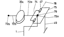
図5に、旋回支承装置の一変形例を示した。この旋回支承装置では、軸受ハウジング33cが鉛直状態にあることを計測センサ61(球形水準器)が指示するように、2つの調節ネジ34c及び34dによって、軸受ハウジング33cを調節することができる。計測センサは、軸受ハウジング33cと固定的に結合している。軸受ハウジングは、軸78周り及び軸68周りで旋回可能である。この旋回の原理は、図13及び図14に示されており、以下の通りである:
【0036】
球状軸受79は、旋回軸受33cを架台支柱1で担持する軸72のための中央係止点を形成する。球状軸受79は、架台支柱1に担持されるか又は架台支柱1に形成され、軸72と固定的に結合するボール(球体)73aを収容する。この軸72には、その両端で旋回連接装置75を支承する連接装置74が同時に固定的に結合する。旋回トング49の旋回により、軸72は、その固有の軸68周りないしボール73a周りで旋回する。図14から分かる通り、この実施例では、軸受ハウジング(スリーブ)33cは、軸72の代わりをする部分軸72a及び72bによって支持される。更に図14から分かる通り、旋回トングの旋回により軸受ハウジング(スリーブ)33cが旋回する。
【0037】
この軸受ハウジング33cを横方向(半径方向)に旋回可能にするために、軸72の端部を、例えば、ボール73bを介してすべり軸受71で支承する。このすべり軸受では、軸方向両向きに旋回できる上、更に軸68周りでも旋回可能である。すべり軸受71は、ネジスピンドル53によって架台支柱1に対するその相対的な高さを変位可能である。この変位の際に、軸72は、球状軸受79内で旋回するが、その時旋回連接装置75には影響を与えない。
【0038】
2つの軸68及び78周りでの旋回運動は、図5に示した好ましい実施例では、調節ネジ34c及び34dによって行われる。調節ネジ34c及び34dは、従来のかさ歯車装置等を介して一方では旋回トング49に、他方ではネジスピンドル53に作用する。
【0039】
図6は、異なる角度から見た図5と同一の旋回支承装置である。図6では、ネジ34dの回動により横方向に変位され、かつ摺動装置48内で上下に滑動可能に支持される旋回トング49を伴う摺動装置48を見出すことができる。摺動装置48は、架台支柱に軸固定的な支持ブロック45内で支持される摺動軸46に沿って摺動可能である。
【0040】
図7は、図5の旋回支承装置の上面図である。
【0041】
図8は、構造部材が一部取り外された図5と同一の旋回支承装置である。図8からは、調節ネジ34cがかさ歯車装置44によってネジスピンドル53を駆動することが見出される。スライダ41の高さを調節しかつそれによって軸78周りでの軸受ハウジング33cの旋回を引き起こすスピンドル53は、かさ歯車装置44の鉛直部分を介して駆動される。スピンドル53は、案内ブロック40内で支持されており、モータによって直接駆動されることも可能であろう。
【0042】
図8では、更に、カバー51が見出されるが、これは、架台支柱の外面を形成し、固定ピントル76で固定され得る。
【0043】
図9及び図10は、図5の実施例に対応する構造であって、それぞれ、ステップモータ54が取り付けられた状態と取り外された状態を示している。比較可能なかさ歯車装置44bは、スライダ48をその軸68周りで旋回させるスピンドル53bを駆動する。モータ54は、その下方領域に、歯付ベルト用歯車77を有し、支持ブロック45内での調節駆動のための結合(ここでは詳細に説明しない)を形成するために、該歯車77には、歯付ベルトを巻き付けることができる。この構造は当業者には既知であり、任意の変形形態を採ることができるので、ここでは詳細な説明はしない。
【0044】
2つのスピンドル53ないしシャフト50を同時に調節することにより、軸受ハウジング33cは、軸78及び軸68に対し斜めに旋回する。軸78及び軸68の各々に関する旋回は、互いに独立に行われても良く、それぞれ他方の旋回状態には影響を受けない。他の類似の水平化(レベル調整)装置とは異なり、調節は、単純なx‐yキャリッジ(スライダ)−しかも旋回可能−によって行われ、そのため操作は、非熟練者であっても極めて容易に行うことができる。この構造は、手動の調節ネジ34c及び34dを電気的駆動装置54によって置きかえることにより更に単純化される。この電気的駆動装置54については、図9にその一例を簡単に示したが、他の構造や配置を採ることもできる。
【0045】
図11は、軸支承体については表示していないが、再び図3の構造について単純化して表した模式図である。軸受パイプ(ハウジング)33の調節は、ここでは、角度センサ61aないし電子的水準器ないし電子的傾きセンサのデータをコンピュータ60による評価及び駆動装置58(ここでは簡単にのみ表示されている)を(駆動)手段とする制御装置59への対応する命令によって自動的に行われる。
【0046】
図12は、本発明の架台の一例の全体構造の概略である。この架台は、架台脚2b、架台支柱1c、及びその構造に基づき傾動安全性を改善するために役立つ装置ケース63を含む。符号65が付されているのは、制動装置であり、これは、制動状態において、支持アーム11cの鉛直軸30c周りでの回動を阻止する。支持アーム11cは、ドイツ特許出願DE 200 19 107(公開番号も同じ)に示されているように、更なる架台アームを担持する。当該ドイツ特許出願の各図及び各図(に関する実施例)についての説明された特徴及び技術的構成は、引用を以って本願に繰り込み、ここに記載されたものと見なす。
【0047】
ドイツ連邦共和国に同日に出願された特許出願(DE 101 15 837.8、ドイツ国整理番号P2152、日本国整理番号P7187EE)の開示内容−とりわけ架台の可能なその他の構造・形態について−も引用をもって本出願に繰り込み、ここに記載されたものとみなす。該特許出願の教示は、本出願の教示と、互いに結合可能である。
【0048】
【発明の効果】
本発明の独立請求項1(第一の視点)及び2(第二の視点)により、所定の課題として掲げた効果が達成される。即ち、第一の視点及び第二の視点の架台は、架台の運動容易性が制限(減殺)されることなく、架台に生じ得るドリフトを抑制するための好適な調節手段を有し、更に従来の架台よりも迅速かつ簡単に、それも身を屈める必要もなく、ドリフト補償調節を行うことができる。
各従属請求項により、更に付加的な効果がそれぞれ達成される。
【図面の簡単な説明】
【図1】架台脚、架台支柱及び旋回アームを有する架台の模式図。
【図2】調節可能な鉛直回動軸受の模式図。
【図3】(a) (部分的に切開された)水平支持アーム内の調節可能鉛直回動軸受の縦断面図。(b) 図3(a)の構造の(切断された一部についての)横断面図。
【図4】スピンドルと、x/yキャリッジ(スライダ)及びy/zキャリッジ(スライダ)とを有する架台の略図。
【図5】架台支柱と結合した旋回支承装置の一変形例。
【図6】異なる角度から見た、図5の旋回支承装置。
【図7】図5の旋回支承装置の上面図。
【図8】一部の構造部材をカットした図5の旋回支承装置。
【図9】ドリフト調節用電気的駆動装置(モータ)を有する、異なる角度から見た図5の旋回支承装置。
【図10】モータを除去し、異なる角度から見た図9の旋回支承装置。
【図11】自動調節(制御)ドリフト補償手段を有する図3の構造の一変形例。
【図12】本発明の架台の一例の全体図。
【図13】本発明の架台のワイヤ式モデルの一例。
【図14】本発明の架台のワイヤ式モデルの他の一例。
【符号の説明】
1a、b、c 架台支柱
2a、b 架台脚
3 雌ネジ
4 手術顕微鏡
5 補助脚
6 コンピュータ
7 制御装置
8 エネルギー源
9 支持アーム
10 平衡アーム
11a、b、c、d 支持部分アーム
12a、b 遠位支持部分アーム
13 カバーコンソール
14 支持支柱
15 支持プレート
16 固定構造部材、カバー
17a、b、c 緩衝層
18a、b、c 非緩衝層
19 緩衝インターフェース、緩衝要素
20 光ファイバーケーブル
21 装置キャビネット
22 ブリッジ
23 鉛直軸
24 コンソール
25 ディスプレイ
26 操作要素
27 ガス圧縮バネ
28 調節手段
29 旋回部材
30a、b、c 支持軸
31 カルダン式懸架部材
32 転動体(ないしすべり部材)
33a、b 軸受ハウジング(ケース)
33c 軸受ハウジング(スリーブ)
34a、b、c、d 調節ネジ(レバー)
35 ブリッジ
36 緩衝ジャーナル
37a、b 雌ネジ
38a、b x/yキャリッジ(スライダ)
39b y/zキャリッジ(スライダ)
40 案内ブロック
41 軸受ブロック(スライダ)
42 軸受
43 案内ロッド
44 かさ歯車装置
45 支持ブロック
46 摺動軸
47 旋回軸
48 摺動装置
49 旋回トング
50 シャフト
51 カバーシェル
52 シャフト案内装置
53 ネジスピンドル
54 サーボモータ(ないしステップモータ)
55 伝動部材
56 矢印
57 矢印
58 モータ
59 制御装置
60 コンピュータ
61 計測センサ
62 伝動装置
63 装置ケース
64 ハンドル
65 制動装置
66 弾性中間層(弾性介装部材)
67 軸支承体
68 軸
69 ハウジング
70 伝動装置
71 すべり軸受
72 軸
73a、b ボール(球体)
74 連接装置
75 旋回連接装置
76 固定スピンドル
77 歯付ベルト用歯車
78 軸
79 球状軸受
III、IV 切断面[0001]
BACKGROUND OF THE INVENTION
The present invention relates generally to a pedestal, such as a surgical microscope pedestal, and more particularly to at least one vertical rotational axis or (at least one) with a pivoting arm pivotably disposed therethrough (internally or in contact therewith). The present invention relates to a gantry having a rotating bearing, a gantry column, and a gantry leg.
[0002]
[Prior art and problems]
Such a cradle needs to support a relatively heavy microscope in such a way that it can be moved for the user with as little resistance as possible. For this reason, the entire transmission device, bearing, and the like are configured as resistancelessly as possible, and efforts are made so that resistance is not generated as much as possible when a user performs an arbitrary motion.
[0003]
By improving the ease of movement of the pedestal, when there is undulation (unevenness) in the installation location (for example, a floor with unevenness), and even when the load applied to the pedestal changes, force-or rotational moment is generated, Each part of the gantry--especially the gantry arm--may perform a drifting motion in a non-braking state. Drift movement is understood as a tendency to perform a side-by-side pivoting movement (around the axis of rotation) or such a pivoting movement of the support arm, which is not desirable for the user.
[0004]
Conventionally, the following three measures have been taken to reduce the drift motion.
[0005]
First means Adjusting the pedestal leg: For example, at least three of the four support legs of the pedestal leg are configured to be adjustable in the height direction, and the level of the pedestal leg is adjusted so that the horizontal state of the pedestal leg is adjusted. To detect. Such adjustment is performed, for example, by FM2 from Mitaka. This ensures precise adjustment, but entails the following disadvantages: That is, since three-point adjustment is performed, it is necessary to perform post-adjustment at the remaining two adjustment points by adjusting one of the three points. It is very difficult for a user who is unfamiliar with such operations to perform the adjustment work quickly and reliably.
[0006]
This creates further disadvantages. That is, first, the pedestal legs must be adjusted by bending to the vicinity of the floor.
[0007]
Secondly, every time the position of the cradle is changed, and every time the load on the cradle arm is changed, a new adjustment must be made, which usually involves all three adjustment points or adjustment means. Everything has to be adjusted anew.
[0008]
Thirdly, due to the mounting position of the adjusting means, the user is required to operate near the floor when performing the adjustment (for example, an area far from the patient and worse sterilized in terms of the operating room). Must have access to.
[0009]
Furthermore, an assistant may be needed to perform the adjustment work. On the other hand, it would be desirable to be able to make adjustments by the surgeon or surgical nurse himself.
[0010]
Second means The second known deformation means includes braking means for increasing rotational friction. With such braking means, the advantage of easy mobility is deliberately reduced in order to reduce drift movement. This is disadvantageous for the user, and for example, the force required to move the support arm increases. The great force is spent making it difficult for the surgeon to perform subsequent operations on the scalpel or other tasks that need to be performed with non-fatigue hands.
[0011]
Third Means A third known variation is known only for conventional ceiling mounts and is irrelevant to the inherent problem of property changes in drift motion due to uneven floors and the like. This is because, in the case of a ceiling mounting stand, usually, a fixed mounting position is provided from the beginning, and the position change on the ceiling surface is not performed. In the case of forming a fixed mounting position, the position is appropriately measured (adjusted) as a matter of course, so that in principle there is no drift problem in the ceiling mounting frame. The adjustment corresponds roughly to the level adjustment (leveling) of the pedestal legs on the floor, but after this adjustment, the position is no longer changed. On the other hand, the load (weight) of the ceiling mount-in some cases even with different weights (load)-creates a new danger that can cause drifting movements.
[0012]
That is, since the strength of the conventional horizontal gantry arm (which is attached to the vertical support) is not infinitely large, an additional support arm attached to the vertical support of this horizontal support arm is provided around the vertical pivot axis. In the case of bending, the first support arm is twisted due to the weight of the additional support arm and the microscope attached thereto. Conversely, when the gantry arm is extended, a bending load is generated on the gantry arm. The purpose and solution of the ceiling mount was to achieve a state where the microscope was maintained at the same height position, both in the bent position of the mount arm and in the extended position of the mount arm. After such an adjustment is made, the adjustment (state) is in principle maintained as it is. Depending on one state (position) change of the gantry arm, its (adjustment) state does not change. There is no position change on the ceiling.
[0013]
Known gantry structures, for example, Draeger-series (Draeger (Germany) is a series of ceiling mounts under the trade names "Movita", "Julian" (this applies to intensive care and intensive care) A close examination of the gantry structure of Kreuzer GmbH (Germany) found no solution. This is because these ceiling mounts do not value the pivoting motility for surgical microscopes with increasing properties.
[0014]
However, “Aus-der-Position-Laufen” is prevented by the increase in frictional force in the rotating bearing. Therefore, with the known ceiling mount for intensive care, the above problem does not occur at all. However, in the case of a microscope mount, the mechanical device is required not to drift when the braking device is released and to be able to move particularly easily. Thus, for example, a lip switch (Mundschalter) is used which allows the surgeon to release the braking device on the one hand by movement of his lips and on the other hand to move the microscope to a new (target) position.
[0015]
Published patent application EP-A-1067419 discloses such a known mechanism for suppressing drift of a ceiling mount in FIGS. 5 to 7 and the description relating to each of these figures. This known drift suppression device operates only in one plane as required. Since the installation after leveling on the ceiling is performed only once, there will be no deviation from the horizontal (unevenness) in the horizontal direction. Conventionally, further leveling or drift compensation measures have been taken on the ceiling mounting base. There was no need. To this extent, the teachings known per se to this person skilled in the art are the incentives to improve the floor mount with respect to the problem mentioned at the outset, i.e. the problem that when the floor mount is moved, the tilt state of the normal mount leg changes. Does not provide any.
[0016]
[Problems to be solved by the invention]
Therefore, an object of the present invention is to provide suitable adjusting means for suppressing a drift that can occur in the gantry without limiting (attenuating) the movability of the gantry, and more quickly and easily than the conventional gantry. In addition, it is to provide a pedestal capable of performing drift compensation adjustment without having to bow down.
[0017]
[Means for Solving the Problems]
The basic idea of the present invention is “Ins-Lot-Stellen”. That is, if perfect alignment is not performed, the horizontal support arm will drift due to gravity around the axis. Therefore, in order to solve this problem, an adjustment for verticalizing the shaft is performed.
[0018]
According to a first aspect of the present invention, a pedestal leg, a vertical support pedestal as a pedestal column protruding upward from the pedestal leg, and a rotary bearing in contact with the rotary shaft or defining the rotary shaft And at least one vertical rotary shaft having a swivel arm rotatably arranged around the rotary shaft, and a shaft support for supporting the rotary shaft and / or the rotary bearing on the vertical support base. in frame of such a, especially surgical microscope stand bets, the rotary shaft or the pivot bearing pivotally and the pedestal without turning the support base in a least two planes in a vertical position relative to each other The arrangement relationship with respect to the legs is configured to be adjustable. Further, according to a second aspect of the present invention, there is provided a pedestal leg, a vertical support pedestal as a pedestal column protruding upward from the pedestal leg, and a rotary bearing that is in contact with the rotary shaft or that defines the rotary shaft. At least one vertical rotary shaft, and a shaft for supporting the rotary shaft and / or the rotary bearing on the vertical support base, in which a swivel arm is disposed so as to be rotatable around the rotary shaft. In particular, in a pedestal such as a surgical microscope pedestal having a support body , the rotating shaft or the rotating bearing can be turned around two turning axes without turning the support pedestal, The positional relationship is adjustable , the first pivot shaft is disposed so as to pass through the rotary shaft or the rotary bearing, and the second pivot shaft is disposed on the rotary shaft or the rotary bearing. It is arranged on the side.
[0019]
DETAILED DESCRIPTION OF THE INVENTION
In the following, preferred embodiments of the invention are shown, which are also the subject of the dependent claims.
It is preferable that the gantry can be controlled by a manual or automatic operation device (adjustment screw, adjustment lever) that is pivoted around the two pivot axes so as to be spaced apart from the two pivot axes.
The gantry further has one swivel shaft fixed at one end to the gantry post by a spherical bearing, and the other swivel shaft passes substantially through the center of the spherical bearing and is in or out of the swivel bearing. The bearing rod is supported in contact with the bearing, and the guide rod is arranged so as to pass substantially through the center of the spherical bearing and perpendicular to one of the shafts, and is articulated to the guide rod with the rotary bearing. The pivoting lever is engaged and the guide rod is preferably aligned coaxially with the other axis.
Preferably, the gantry further comprises automatic remote control means including an automatic device and is computer controlled and operated via at least one of an electronic level, a tilt sensor or an angle sensor.
[0020]
A pedestal leg can be understood as any device that supports the pedestal against the floor surface. The pedestal legs can be conventional pedestal legs, but can also be trolleys, traveling winches, and the like. The gantry column can be understood not only as a conventional vertical column that is coupled to the gantry leg, but also as a support arm that can be moved via a rail, a traveling winch (Laufkatze), or the like.
[0021]
According to a preferred embodiment of the gantry of the present invention, the rotating shaft and the pivot bearing (or housing) are arranged via the gantry column (that is, in the gantry column or at the gantry column), and the adjusting means includes: It is advantageous if it is ensured by adjusting screws which are preferably arranged in a horizontal plane and at an angle of approximately 90 °.
[0022]
The adjusting screw is preferably screw-supported on the gantry post and directly contacts the rotating bearing (housing).
[0023]
In a further advantageous embodiment of the cradle according to the invention, an elastic interposition member (layered member) is arranged between the rotary bearing (housing) and the bearing pipe or support arm.
[0024]
Furthermore, according to a preferred embodiment of the invention, the swivel bearing and / or the rotary shaft are supported directly or indirectly on the gantry column by means of a shaft bearing (or a pivotal bearing device axiales Dreh-Schwenklager).
[0025]
In a further embodiment of the cradle of the present invention, automatic remote control is performed. In this case, any movable member (especially screw spindle, adjustment screw) involved in the adjustment (control) of the gantry can be automatically remote-controlled. Further, preferably, the gantry is provided with an automatic control system. The automatic control system operates via at least one of, for example, an electronic level (Libellen), a tilt sensor, an angle sensor, or a similar structural element, preferably computer controlled, preferably directly or indirectly with a pivot bearing. To do.
[0026]
Furthermore, in a preferred embodiment of the gantry of the present invention, a transmission device is arranged between at least one operating element (such as an adjusting screw) or a motor and a rotatable bearing (or housing) that can rotate.
[0027]
In a further preferred embodiment of the cradle of the invention, the gantry post is configured such that its relative position to the cradle leg is variable and adjustable and / or controllable.
[0028]
Other embodiments of the cradle of the invention are found from the respective dependent claims and the respective drawings.
[0029]
【Example】
Embodiments of the present invention will be described in detail with reference to the drawings. It should be noted that the reference numerals attached to the claims are for facilitating the understanding of the invention and are not intended to limit the present invention to the illustrated embodiment. The following examples are also for facilitating the understanding of the invention, and are not intended to exclude substitutions and changes that can be made by those skilled in the art without departing from the technical idea of the present invention. This is the same even after correction.
[0030]
1 to 14 are schematically described, wherein the same reference numerals denote the same structural members or elements, and the same reference numerals are used for the same purposes. It means a slightly different structural member or element having a similar function.
[0031]
As is clear from FIG. 1, basically important are the
[0032]
FIG. 3A is a schematic diagram of the structure of the adjusting device. Since the bearing housing (or case) 33b is movably supported by the shaft support body 67, the bearing housing 33b is elastically supported by the adjusting
[0033]
FIG. 3 (b) shows that two or more adjustment screws 34 can displace the bearing housing 33 b inside the
[0034]
FIG. 4 is a schematic diagram of the structure of an adjusting device that uses two
[0035]
FIG. 5 shows a modification of the turning support device. In this swivel support device, the bearing
[0036]
The
[0037]
In order to make the bearing
[0038]
The pivoting movement about the two
[0039]
FIG. 6 is the same turning support device as FIG. 5 seen from a different angle. In FIG. 6, it is possible to find a sliding
[0040]
7 is a top view of the swivel support device of FIG.
[0041]
FIG. 8 is the same swivel support device as in FIG. 5 with the structural member partially removed. It can be seen from FIG. 8 that the adjusting
[0042]
In FIG. 8, a
[0043]
FIGS. 9 and 10 are structures corresponding to the embodiment of FIG. 5 and show a state in which the
[0044]
By simultaneously adjusting the two
[0045]
FIG. 11 is a schematic diagram showing again the structure of FIG. 3 again, although the shaft support is not shown. The adjustment of the bearing pipe (housing) 33 is performed here by evaluating the angle sensor 61a or the electronic level or the electronic tilt sensor with the evaluation by the computer 60 and the driving device 58 (only shown here). This is automatically performed by a corresponding command to the
[0046]
FIG. 12 is an outline of the overall structure of an example of the gantry of the present invention. This pedestal includes a pedestal leg 2b, a pedestal column 1c, and a
[0047]
Disclosure of patent application filed on the same day in the Federal Republic of Germany (DE 101 15 837.8, German docket number P2152, Japanese docket number P7187EE)-especially with regard to other structures and forms that can be mounted-this application with reference It is considered that it was described here. The teachings of the patent application can be combined with the teachings of the present application.
[0048]
【The invention's effect】
According to the independent claims 1 (first viewpoint) and 2 (second viewpoint) of the present invention, the effects listed as the predetermined subject are achieved. That is, the mounts of the first viewpoint and the second viewpoint have suitable adjusting means for suppressing drift that may occur in the mounts without limiting (attenuating) the ease of movement of the mounts. Drift compensation adjustments can be made more quickly and easily than the pedestal, without having to bow down.
Each additional claim achieves further additional effects.
[Brief description of the drawings]
FIG. 1 is a schematic diagram of a gantry having a gantry leg, a gantry column, and a swivel arm.
FIG. 2 is a schematic view of an adjustable vertical rotation bearing.
3A is a longitudinal cross-sectional view of an adjustable vertical pivot bearing in a horizontal support arm (partially cut). FIG. (B) A cross-sectional view of the structure of FIG.
FIG. 4 is a schematic view of a gantry having a spindle and an x / y carriage (slider) and a y / z carriage (slider).
FIG. 5 shows a modified example of a swivel support device combined with a gantry post.
6 shows the swivel support device of FIG. 5 as seen from a different angle.
7 is a top view of the swivel support device of FIG. 5. FIG.
8 is a swivel support device of FIG. 5 with some structural members cut.
9 shows the swivel bearing device of FIG. 5 from different angles with an electrical drive (motor) for drift adjustment.
FIG. 10 shows the swivel support device of FIG. 9 with the motor removed and viewed from a different angle.
11 shows a variation of the structure of FIG. 3 having automatic adjustment (control) drift compensation means.
FIG. 12 is an overall view of an example of a gantry according to the present invention.
FIG. 13 shows an example of a wire model of the gantry of the present invention.
FIG. 14 shows another example of the wire model of the gantry of the present invention.
[Explanation of symbols]
1a, b,
33a, b Bearing housing (case)
33c Bearing housing (sleeve)
34a, b, c, d Adjustment screw (lever)
35 Bridge 36 Buffer journal 37a, b
39b y / z carriage (slider)
40
42
55
67
74 articulating
Claims (5)
前記架台脚(2)から上方に突き出た架台支柱としての鉛直支持台(1)と、
回転軸(30)に接して又は前記回転軸(30)を規定する回動軸受(33)の内部に、前記回転軸(30)の周りに回転可能に旋回アーム(11)が配された、少なくとも1つの鉛直回転軸(30)と、
前記回転軸(30)及び/又は前記回動軸受(33)を前記鉛直支持台(1)の上で支持するための軸支承体(67)とを有する架台において、
前記回転軸(30)又は前記回動軸受(33)は、互いに垂直な位置関係にある少なくとも2つの面内で前記支持台(1)を旋回させることなく旋回可能かつ前記架台脚(2)に対する配置関係が調節可能に構成される
ことを特徴とする架台。Pedestal leg (2),
A vertical support (1) as a support column protruding upward from the mount leg (2);
A swivel arm (11) is disposed in contact with the rotating shaft (30) or inside the rotating bearing (33) defining the rotating shaft (30) so as to be rotatable around the rotating shaft (30). At least one vertical axis of rotation (30);
In a gantry having a shaft support (67) for supporting the rotary shaft (30) and / or the rotary bearing (33) on the vertical support base (1) ,
The rotary shaft (30) or the rotary bearing (33) can turn without turning the support base (1) in at least two planes that are perpendicular to each other, and can rotate with respect to the pedestal leg (2). A gantry characterized in that the arrangement relationship is adjustable.
前記架台脚(2)から上方に突き出た架台支柱としての鉛直支持台(1)と、
回転軸(30)に接して又は前記回転軸(30)を規定する回動軸受(33)の内部に、前記回転軸(30)の周りに回転可能に旋回アーム(11)が配された、少なくとも1つの鉛直回転軸(30)と、
前記回転軸(30)及び/又は前記回動軸受(33)を前記鉛直支持台(1)の上で支持するための軸支承体(67)とを有する架台において、
前記回転軸(30)又は前記回動軸受(33)は、2つの旋回軸(68、78)周りで前記支持台(1)を旋回させることなく旋回可能であり、その前記架台脚(2)に対する配置関係が調節可能であると共に、該第1の旋回軸(68)は該回転軸(30)又は該回動軸受(33)を通過するように配され、かつ該第2の旋回軸(78)は、該回転軸(30)又は該回動軸受(33)の側方に配される
ことを特徴とする架台。Pedestal leg (2),
A vertical support (1) as a support column protruding upward from the mount leg (2);
A swivel arm (11) is disposed in contact with the rotating shaft (30) or inside the rotating bearing (33) defining the rotating shaft (30) so as to be rotatable around the rotating shaft (30). At least one vertical axis of rotation (30);
In a gantry having a shaft support (67) for supporting the rotary shaft (30) and / or the rotary bearing (33) on the vertical support base (1) ,
The rotating shaft (30) or the rotating bearing (33) can be turned around the two turning shafts (68, 78) without turning the support base (1) , and the gantry leg (2) The first pivot axis (68) is arranged to pass through the rotary axis (30) or the pivot bearing (33), and the second pivot axis ( 78) is provided on the side of the rotating shaft (30) or the rotary bearing (33).
ことを特徴とする請求項2に記載の架台。The pivoting around the two pivot axes (68, 78) can be controlled by a manual or automatic operating device (34c, 34d) spaced from the two pivot axes (68, 78). The gantry according to claim 2.
案内ロッド(47)は、前記球状軸受(79)の中心を実質的に通過するようにかつ前記一方の軸(68)に対し垂直に配され、該案内ロッド(47)には、前記回動軸受(33c)と関節的に結合する旋回レバー(49)が係合し、該案内ロッド(47)は、前記他方の軸(78)と同軸的に整列すること
を特徴とする請求項3に記載の架台。The one pivot shaft (68) is fixed to the gantry post (1) at one end by a spherical bearing (79), and the other pivot shaft (78) substantially has the center of the spherical bearing (79). And is supported via the pivot bearing (33c), and the guide rod (47) passes substantially through the center of the spherical bearing (79) and the one shaft ( 68), and the guide rod (47) is engaged with a turning lever (49) that is articulated with the rotary bearing (33c), and the guide rod (47) A pedestal according to claim 3, characterized in that it is aligned coaxially with the other shaft (78).
ことを特徴とする請求項1〜4の一に記載の架台。5. The automatic remote control means comprises an automatic device and is computer controlled and activated via at least one of an electronic level (61), a tilt sensor or an angle sensor. Described stand.
Applications Claiming Priority (2)
| Application Number | Priority Date | Filing Date | Title |
|---|---|---|---|
| DE10123166.0 | 2001-03-31 | ||
| DE10123166A DE10123166A1 (en) | 2001-03-31 | 2001-03-31 | Frame, especially for operation microscope, has rotation axis or rotary bearing that can be manually or motor adjusted in the vertical in at least two mutually perpendicular planes relative to frame foot |
Publications (2)
| Publication Number | Publication Date |
|---|---|
| JP2002315759A JP2002315759A (en) | 2002-10-29 |
| JP4213902B2 true JP4213902B2 (en) | 2009-01-28 |
Family
ID=7684564
Family Applications (1)
| Application Number | Title | Priority Date | Filing Date |
|---|---|---|---|
| JP2002098791A Expired - Fee Related JP4213902B2 (en) | 2001-03-31 | 2002-04-01 | Mounting platform, especially for operating microscope |
Country Status (4)
| Country | Link |
|---|---|
| US (1) | US6997425B2 (en) |
| EP (1) | EP1251380A3 (en) |
| JP (1) | JP4213902B2 (en) |
| DE (1) | DE10123166A1 (en) |
Cited By (1)
| Publication number | Priority date | Publication date | Assignee | Title |
|---|---|---|---|---|
| US8570120B2 (en) | 2008-12-26 | 2013-10-29 | Kabushiki Kaisha Toshiba | Heat insulating waveguides separated by an air gap and including two planar reflectors for controlling radiation power from the air gap |
Families Citing this family (15)
| Publication number | Priority date | Publication date | Assignee | Title |
|---|---|---|---|---|
| DE10123166A1 (en) * | 2001-03-31 | 2002-10-10 | Leica Microsystems | Frame, especially for operation microscope, has rotation axis or rotary bearing that can be manually or motor adjusted in the vertical in at least two mutually perpendicular planes relative to frame foot |
| DE20218693U1 (en) * | 2002-12-03 | 2003-02-13 | Leica Microsystems (Schweiz) Ag, Heerbrugg | Tripod for a surgical microscope |
| DE20218691U1 (en) * | 2002-12-03 | 2003-02-27 | Leica Microsystems (Schweiz) Ag, Heerbrugg | Tripod for a surgical microscope |
| JP4488292B2 (en) | 2004-03-03 | 2010-06-23 | オリンパス株式会社 | Surgical microscope |
| US7770860B1 (en) | 2005-11-10 | 2010-08-10 | Modular Services Company | Medical service system on articulating arm with electromagnetic brakes |
| US7971396B1 (en) | 2007-04-10 | 2011-07-05 | Modular Services Company | Modular medical services unit with secure console |
| US8400094B2 (en) | 2007-12-21 | 2013-03-19 | Intuitive Surgical Operations, Inc. | Robotic surgical system with patient support |
| US8197154B2 (en) * | 2008-10-31 | 2012-06-12 | Midmark Corporation | Articulating joint for dental or medical lights |
| US9644782B2 (en) * | 2013-10-23 | 2017-05-09 | Hunter Engineering Company | Wheel alignment system cabinet structure |
| CN107514531A (en) * | 2017-09-05 | 2017-12-26 | 苏州优银机械有限公司 | It is a kind of to load the industrial cantilever strengthened |
| CN107559564A (en) * | 2017-09-05 | 2018-01-09 | 苏州优银机械有限公司 | A kind of compact industry cantilever of built-in motor |
| CN109480779A (en) * | 2018-11-07 | 2019-03-19 | 苏州先康科技有限公司 | A kind of novel skin detection device |
| US11199289B2 (en) * | 2019-09-18 | 2021-12-14 | Carl Zeiss Meditec Ag | Apparatus, surgical microscopy system, and method for compensating a balancing error in a stand for a surgical microscope |
| CN112761378A (en) * | 2021-01-28 | 2021-05-07 | 吉林师范大学博达学院 | Traditional village building protection device |
| DE102021121220A1 (en) | 2021-08-16 | 2023-02-16 | Jungheinrich Aktiengesellschaft | Adjustable suspension for a scanning device of an industrial truck and combination of such a suspension with a scanning device of an industrial truck |
Family Cites Families (19)
| Publication number | Priority date | Publication date | Assignee | Title |
|---|---|---|---|---|
| US2469904A (en) * | 1947-01-10 | 1949-05-10 | Edward A Szuba | Gauge support |
| US2560001A (en) * | 1948-09-10 | 1951-07-10 | Scholfield | Filing chair |
| US2970798A (en) * | 1956-10-23 | 1961-02-07 | Central Scient Co | Laboratory clamps |
| US2898068A (en) * | 1957-02-26 | 1959-08-04 | Robert L Warren | Support having three axes of adjustment and single locking handle |
| US3044740A (en) * | 1959-10-20 | 1962-07-17 | Nat Res Dev | Supports for high sensitivity devices |
| US3167292A (en) * | 1963-12-12 | 1965-01-26 | Nathan L Meyerowitz | Bracket |
| US3551022A (en) * | 1969-01-27 | 1970-12-29 | Mattel Inc | Optical stand |
| US3672620A (en) * | 1970-11-17 | 1972-06-27 | Anton Fink | Height gauge |
| US4284257A (en) * | 1979-09-05 | 1981-08-18 | Murkens David W | Precision surface gage |
| US4473074A (en) * | 1981-09-28 | 1984-09-25 | Xanar, Inc. | Microsurgical laser device |
| US5118058A (en) * | 1991-06-20 | 1992-06-02 | Panavise Products, Inc. | Universal adjustable mount |
| JPH0773587B2 (en) * | 1993-03-18 | 1995-08-09 | 三鷹光器株式会社 | Biaxial balance adjustment structure for medical stand device |
| DE59610558D1 (en) * | 1995-10-12 | 2003-07-31 | Leica Ag Heerbrugg | TRIPOD |
| US6532108B1 (en) * | 1998-07-31 | 2003-03-11 | Leica Microsystems Ag | Operating microscope stand for X-Y displacement |
| US5996946A (en) * | 1998-08-07 | 1999-12-07 | Boice Industrial Corporation | Height gauge support stand |
| DE50014939D1 (en) | 1999-07-03 | 2008-03-20 | Leica Microsystems | ceiling mount |
| US6334594B1 (en) * | 2000-05-12 | 2002-01-01 | Boice Industrial Corp. | Adjustable indicator mount |
| DE10115837A1 (en) | 2001-03-31 | 2002-11-14 | Leica Microsystems | Tripod, especially for a surgical microscope |
| DE10123166A1 (en) * | 2001-03-31 | 2002-10-10 | Leica Microsystems | Frame, especially for operation microscope, has rotation axis or rotary bearing that can be manually or motor adjusted in the vertical in at least two mutually perpendicular planes relative to frame foot |
-
2001
- 2001-03-31 DE DE10123166A patent/DE10123166A1/en not_active Ceased
-
2002
- 2002-03-27 US US10/107,548 patent/US6997425B2/en not_active Expired - Fee Related
- 2002-03-28 EP EP02007140A patent/EP1251380A3/en not_active Withdrawn
- 2002-04-01 JP JP2002098791A patent/JP4213902B2/en not_active Expired - Fee Related
Cited By (1)
| Publication number | Priority date | Publication date | Assignee | Title |
|---|---|---|---|---|
| US8570120B2 (en) | 2008-12-26 | 2013-10-29 | Kabushiki Kaisha Toshiba | Heat insulating waveguides separated by an air gap and including two planar reflectors for controlling radiation power from the air gap |
Also Published As
| Publication number | Publication date |
|---|---|
| US20020185583A1 (en) | 2002-12-12 |
| US6997425B2 (en) | 2006-02-14 |
| EP1251380A2 (en) | 2002-10-23 |
| DE10123166A1 (en) | 2002-10-10 |
| JP2002315759A (en) | 2002-10-29 |
| EP1251380A3 (en) | 2003-12-03 |
Similar Documents
| Publication | Publication Date | Title |
|---|---|---|
| JP4213902B2 (en) | Mounting platform, especially for operating microscope | |
| US12127863B2 (en) | Patient positioning support structure | |
| US11679051B2 (en) | Patient positioning support structure | |
| JP4041536B2 (en) | Stand | |
| JP2825721B2 (en) | Medical optical equipment stand device | |
| JP4041669B2 (en) | Stand device | |
| RU2656553C2 (en) | Ultrasound system control panel and display lift | |
| US4881709A (en) | Stand mechanism for a medical optical equipment | |
| EP3479775B1 (en) | Surgical robot and mechanical arm thereof | |
| JP3283603B2 (en) | Motor-driven mount | |
| JP4102046B2 (en) | Stand | |
| JPH029820B2 (en) | ||
| JPH09168569A (en) | Table for electrophysiology | |
| JP4473604B2 (en) | Stand device for medical optical equipment | |
| JP2003111776A (en) | Stand | |
| JP3150979B2 (en) | Ophthalmic equipment | |
| US20100116082A1 (en) | Multiaxis Counterbalance and Positioning System Using a Spatial Linkage | |
| JP4394344B2 (en) | Support device for optical device | |
| EP1101139B1 (en) | Operating microscope stand for x-y displacement | |
| JP4118549B2 (en) | Mounting base, especially for operating microscope | |
| JP3670325B2 (en) | Medical device holding device | |
| JP3350112B2 (en) | Mechanical control unit for operating microscope combined with pedestal | |
| US20220104915A1 (en) | Robotic surgical systems and robotic arm carts thereof | |
| CN113729953A (en) | Initial adjustment vertical arm of surgical robot | |
| JPH06258580A (en) | Microscope supporting device for operation |
Legal Events
| Date | Code | Title | Description |
|---|---|---|---|
| A621 | Written request for application examination |
Free format text: JAPANESE INTERMEDIATE CODE: A621 Effective date: 20050124 |
|
| A131 | Notification of reasons for refusal |
Free format text: JAPANESE INTERMEDIATE CODE: A131 Effective date: 20080513 |
|
| A521 | Request for written amendment filed |
Free format text: JAPANESE INTERMEDIATE CODE: A523 Effective date: 20080811 |
|
| TRDD | Decision of grant or rejection written | ||
| A01 | Written decision to grant a patent or to grant a registration (utility model) |
Free format text: JAPANESE INTERMEDIATE CODE: A01 Effective date: 20081014 |
|
| A01 | Written decision to grant a patent or to grant a registration (utility model) |
Free format text: JAPANESE INTERMEDIATE CODE: A01 |
|
| A61 | First payment of annual fees (during grant procedure) |
Free format text: JAPANESE INTERMEDIATE CODE: A61 Effective date: 20081031 |
|
| FPAY | Renewal fee payment (event date is renewal date of database) |
Free format text: PAYMENT UNTIL: 20111107 Year of fee payment: 3 |
|
| R150 | Certificate of patent or registration of utility model |
Free format text: JAPANESE INTERMEDIATE CODE: R150 |
|
| S111 | Request for change of ownership or part of ownership |
Free format text: JAPANESE INTERMEDIATE CODE: R313113 |
|
| FPAY | Renewal fee payment (event date is renewal date of database) |
Free format text: PAYMENT UNTIL: 20111107 Year of fee payment: 3 |
|
| R350 | Written notification of registration of transfer |
Free format text: JAPANESE INTERMEDIATE CODE: R350 |
|
| FPAY | Renewal fee payment (event date is renewal date of database) |
Free format text: PAYMENT UNTIL: 20111107 Year of fee payment: 3 |
|
| FPAY | Renewal fee payment (event date is renewal date of database) |
Free format text: PAYMENT UNTIL: 20121107 Year of fee payment: 4 |
|
| FPAY | Renewal fee payment (event date is renewal date of database) |
Free format text: PAYMENT UNTIL: 20121107 Year of fee payment: 4 |
|
| FPAY | Renewal fee payment (event date is renewal date of database) |
Free format text: PAYMENT UNTIL: 20131107 Year of fee payment: 5 |
|
| R250 | Receipt of annual fees |
Free format text: JAPANESE INTERMEDIATE CODE: R250 |
|
| R250 | Receipt of annual fees |
Free format text: JAPANESE INTERMEDIATE CODE: R250 |
|
| R250 | Receipt of annual fees |
Free format text: JAPANESE INTERMEDIATE CODE: R250 |
|
| LAPS | Cancellation because of no payment of annual fees |