JP4199409B2 - Filtration device - Google Patents
Filtration device Download PDFInfo
- Publication number
- JP4199409B2 JP4199409B2 JP2000138832A JP2000138832A JP4199409B2 JP 4199409 B2 JP4199409 B2 JP 4199409B2 JP 2000138832 A JP2000138832 A JP 2000138832A JP 2000138832 A JP2000138832 A JP 2000138832A JP 4199409 B2 JP4199409 B2 JP 4199409B2
- Authority
- JP
- Japan
- Prior art keywords
- filter
- stock solution
- filtrate
- filtration
- residual
- Prior art date
- Legal status (The legal status is an assumption and is not a legal conclusion. Google has not performed a legal analysis and makes no representation as to the accuracy of the status listed.)
- Expired - Fee Related
Links
- 238000001914 filtration Methods 0.000 title claims description 41
- 239000000706 filtrate Substances 0.000 claims description 42
- 239000011550 stock solution Substances 0.000 claims description 36
- 238000005192 partition Methods 0.000 claims description 9
- 239000012141 concentrate Substances 0.000 claims description 4
- 238000004891 communication Methods 0.000 claims description 2
- 239000012530 fluid Substances 0.000 claims 1
- 239000007788 liquid Substances 0.000 description 7
- 239000005909 Kieselgur Substances 0.000 description 4
- VYPSYNLAJGMNEJ-UHFFFAOYSA-N Silicium dioxide Chemical compound O=[Si]=O VYPSYNLAJGMNEJ-UHFFFAOYSA-N 0.000 description 4
- 239000000243 solution Substances 0.000 description 3
- 238000010586 diagram Methods 0.000 description 2
- 230000000694 effects Effects 0.000 description 2
- 238000003825 pressing Methods 0.000 description 2
- 238000011084 recovery Methods 0.000 description 2
- 238000013459 approach Methods 0.000 description 1
- 239000011248 coating agent Substances 0.000 description 1
- 238000000576 coating method Methods 0.000 description 1
- 230000007423 decrease Effects 0.000 description 1
- 238000004519 manufacturing process Methods 0.000 description 1
Images


Landscapes
- Filtration Of Liquid (AREA)
Description
【0001】
【産業上の利用分野】
本願発明は、系内に導入された原液を最後まで濾過する装置に関する。
【0002】
【従来の技術】
珪藻土を利用する濾過装置において、濾過機本体内に残留する原液を全量濾過することは生産効率上有用なことである。円筒状フィルターを備えた珪藻土濾過装置において、上記原液を濾過回収する場合、空気圧を利用して該原液を濾過するのが一般的である。そしてこの場合残留原液を処理するフィルターは、水平板式でも良いが、回収時間を短縮するために濾過面積の多い円筒状フィルター等を底部に立設するのが効率的である。
【0003】
従来、濾過面に珪藻土等の濾過助剤をコーティングして原液を濾過し、ならびに濾過後濾過機本体内に残留した原液を濾過処理するものとして、図1〜図3に示すような濾過機本体の底部に残留液回収用のフィルターを備えた円筒状フィルター方式の濾過装置や多段式水平板状フィルター方式の濾過装置等が知られている。これらの濾過装置の残液回収用のフィルター部の形状としては、図1に示すような円筒状フィルターや図3に示す多段式水平板状フィルター等が用いられてきた。
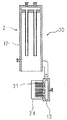
そこで例えば図1〜図2に示す従来の濾過装置1は、主に密閉円筒状をした濾過機本体2と、該本体2内の上部より吊設された上部円筒状フィルター3と、底部に立設され残留原液濾過用の下部円筒状フィルター4より構成されている。濾過機本体2の側壁部5には原液入口6、上壁部7には上部濾過液出口8と残留原液押圧用の空気入口9、底壁部10には残留原液用の下部濾過液出口11がそれぞれ設けられている。
そして本体2は、上部本体12と下部本体13とに分割されていて、連結部材14により下部本体13は開閉自在となっている。上部本体12の上方部には、上部濾過液室15が上部区画壁16により区画形成されており、上部円筒状フィルター3は、該濾過液室15を介して濾過液出口8ならびに空気入口9と連通している。一方底部には、下部濾過液室17が下部区画壁18により区画形成されており、下部円筒状フィルター4は、該濾過液室17を介して下部濾過液出口11と連通している。
【0004】
上部円筒状フィルター3により濾過された液は、濾過液弁19と濾過液管20を通り濾過液タンク21へ導かれる。また、下部円筒状フィルター4により濾過された液は、濾過液管20に連通された残留液濾過管22と該管20を通り濾過液タンク21へ導かれる。
原液入口6には、ポンプ23が接続されていて、原液は導入弁24と導入管25を通って原液タンク26より濾過機本体2内に導入される。
空気入口9は、高圧空気源27に連通されていて、空気弁28を介して高圧空気が濾過機本体2内へ導入される構成となっている。
【0005】
かく構成されて成る従来の濾過装置1により原液を濾過するには、先ず通常の手段で珪藻土等の濾過助剤を上下部の円筒状フィルター3、4にコーティングした後、ポンプ23により原液を濾過機本体2に供給し、該フィルター3、4により濾過する。このとき濾過液弁19と導入弁24は開、空気弁28は閉にしておく。濾過液は、上下部の濾過液出口8、11より濾過液タンク21に導かれ回収される。原液が濾過機本体2内に残っている状態での濾過工程(以下通常濾過工程という)の終了後、濾過液弁19と導入弁24を閉にし空気弁28を開いて、濾過機本体2内に高圧空気を導入し、残留原液濾過用の下部円筒状フィルター4にて該本体2内に残っている原液を濾過処理する(以下残留原液濾過工程という)。このとき濾過液は、残留原液濾過管22と濾過管液20を通り濾過液タンク21へ導かれる。そして、この残留原液濾過工程時に上部円筒状フィルター3は逆洗され、その表面に付着している濾過助剤は、剥離除去される。
【0006】
【発明が解決しようとする課題】
しかし、前記した従来の残留原液濾過用の円筒状フィルターあるいは多段式平板状フィルターのような構造では、その表面部に付着させた濾過助剤を残留原液濾過工程終了後、除去するのがめんどうであった。
そこで本願発明者は鋭意研究の結果、平板状のフィルターを平行に多数下部区画壁上に立設すれば、櫛の刃状に形成されたスクレーパにより一気に濾過助剤を除去することが可能であることを知見し本願発明を完成させた。
【0007】
【課題を解決するための手段】
すなわち本願発明は、上壁部に濾過液送出口、底壁部に残留原液用の下部濾過液出口、側壁部に原液入口をそれぞれ備え筒状に形成された濾過機本体、濾過液送出口に連通して設置された上部円筒状フィルター、下部濾過液出口に連通して下部区画壁に、互いに平行に複数立設された残留原液濾過用の縦型平板状フィルターより構成されることを特徴とする濾過装置である。
【0008】
【発明の実施の形態】
次ぎに図4〜図8を基に本願発明を詳細に説明する。
先ず30は、本願発明に係る濾過装置で、また31は残留原液濾過用の縦型平板状フィルターで、コ字状をしていて下部区画壁18上に多数平行して立設されている。その内部には濾過液通液室32が形成され、該室32は、下部濾過液室17を介して下部濾過液出口11と連通している。一般的に濾過機本体2は円筒形をしているため、縦型平板状フィルター31の長さLn(図5参照)は、中央部が一番長く、周辺部に近ずくにつれて短くなる。
そして、図7に示すのは縦型平板状フィルター31に付着している濾過助剤33を残留原液濾過工程終了後、除去するためのスクレーパ34である。スクレーパ34の刃35は、図8に示すように縦型平板状フィルター31の隙間36に挿入され、そのまま例えば図8において前後方向に移動させることにより、縦型平板状フィルター31上に付着している濾過助剤33を除去することができる
【0009】
また、本願発明に係る縦型平板状フィルター31は、その構造上フィルター自体の強度が強化され、その幅B(図6参照)を薄くすることができそれだけ下部区画壁18上に多数設置することができる。よって例えば図2に示す下部円筒状フィルター4と比較した場合、同じ濾過面積を想定すると、縦型平板状フィルター31の高さH(図6参照)を下部円筒状フィルター4の高さh(図9参照)より低くすることができる。その結果、より低位まで残留原液押圧用の高圧空気を加えることができ、効率的に残留原液を濾過することができる。以下に上記の効果を数値的に示す。
【0010】
実施例として残液回収部の濾過面積を例えば0.5m2とした場合、本願発明による縦型平板式フィルター31の高さHと従来装置の下部円筒状フィルター4の高さhとを比較してみる。
下部円筒状フィルター4の場合は、直径D400mmの下部区画壁18上に直径d42mm(図9参照)のものを19本設置でき、このとき高さhは200mmになる。円筒状の下部円筒状フィルター4に付着した濾過助剤除去の作業性を考慮すると、19本程度が限度である。
一方、本願発明による縦型平板状フィルター31の場合、同様に直径D400mmの下部区画壁18上に幅B12mmのものを図5のごとく平行にピッチP30mm(図5参照)で9枚も設置でき、このときの高さHは95mmとなる。このとき縦型平板状フィルター31のそれぞれの長さLnは、L1:370mm、L2:356mm、L3:332mm、L4:270mm、L5:168mmであった。
以上の比較により縦型平板状フィルター31の高さHは、円筒状の下部円筒状フィルター4の高さhの半分以下にすることができる。このことは、それだけ長い期間残留原液濾過工程において、高圧空気を加圧することができ、効率的な残留原液濾過工程を行うことができる。
【0011】
【発明の効果】
本願発明は以上のように構成されており、残留原液濾過工程終了後、残留原液濾過用の縦型平板状フィルターに付着している濾過助剤を簡単に除去することができる。また、残留原液濾過用の高圧空気をより長い間加圧できるため、残留原液濾過工程をより迅速に終了させることができる。
【図面の簡単な説明】
【図1】従来の濾過装置の正面断面図とフローシート図
【図2】図1の2−2視断面図
【図3】従来の濾過装置の正面断面図
【図4】本願発明に係る濾過装置の正面断面図とフローシート図
【図5】図4の5−5視断面図
【図6】図5の6−6視断面図
【図7】濾過助剤を除去するためのスクレーパの正面図
【図8】スクレーパの作動図
【図9】図2の9−9視断面図
【符号の説明】
1 従来の濾過装置
2 濾過機本体
3 上部円筒状フィルター
4 残留原液濾過用の下部円筒状フィルター
6 原液入口
8 上部濾過液出口
9 空気入口
11 下部濾過液出口
15 上部濾過液室
17 下部濾過液室
19 濾過液弁
20 濾過液管
21 濾過液タンク
22 残留原液濾過液管
23 ポンプ
24 導入弁
25 導入管
26 原液タンク
27 高圧空気源
28 空気弁
30 本願発明に係る濾過装置
31 縦型平板状フィルター
32 濾過液濾過液通液室
33 濾過助剤
34 スクレーパ
35 スクレーパの刃
36 隙間[0001]
[Industrial application fields]
The present invention relates to an apparatus for filtering a stock solution introduced into a system to the end.
[0002]
[Prior art]
In a filtration device using diatomaceous earth, it is useful in terms of production efficiency to filter the whole amount of the stock solution remaining in the filter body. In a diatomaceous earth filtration apparatus equipped with a cylindrical filter, when the stock solution is filtered and recovered, the stock solution is generally filtered using air pressure. In this case, the filter for treating the residual stock solution may be a horizontal plate type. However, in order to shorten the recovery time, it is efficient to erect a cylindrical filter or the like having a large filtration area at the bottom.
[0003]
Conventionally, a filter body as shown in FIGS. 1 to 3 is used to filter the stock solution by coating the filter surface with a filter aid such as diatomaceous earth and to filter the stock solution remaining in the filter body after filtration. There are known a cylindrical filter type filtration device provided with a filter for collecting a residual liquid at the bottom, a multistage horizontal plate filter type filtration device, and the like. As the shape of the filter portion for collecting the residual liquid of these filtration devices, a cylindrical filter as shown in FIG. 1 or a multistage horizontal plate filter as shown in FIG. 3 has been used.
Therefore, for example, the
The
[0004]
The liquid filtered by the upper
A
The
[0005]
In order to filter the stock solution with the
[0006]
[Problems to be solved by the invention]
However, in the structure such as the conventional cylindrical filter for residual stock solution filtration or the multistage flat plate filter, it is troublesome to remove the filter aid adhering to the surface portion after the residual stock solution filtration step. there were.
Therefore, as a result of earnest research, the inventor of the present application can remove filter aids at once by a scraper formed in a comb blade shape if a large number of flat filters are erected on the lower partition wall in parallel. The present invention was completed by discovering this fact.
[0007]
[Means for Solving the Problems]
That is, the present invention provides a filter main body formed in a cylindrical shape with a filtrate outlet on the upper wall, a lower filtrate outlet for the residual concentrate on the bottom wall, and a concentrate inlet on the side wall, and a filtrate outlet. An upper cylindrical filter installed in communication with the lower filtrate outlet and a plurality of vertical flat filters for residual stock solution installed in parallel with each other on the lower partition wall. It is a filtration device.
[0008]
DETAILED DESCRIPTION OF THE INVENTION
Next, the present invention will be described in detail with reference to FIGS.
First, 30 is a filtration device according to the present invention, and 31 is a vertical flat plate filter for filtering residual stock solution, which is U-shaped and is erected in parallel on the
FIG. 7 shows a
In addition, the vertical
[0010]
As an example, when the filtration area of the residual liquid recovery part is 0.5 m 2 , for example, the height H of the
In the case of the lower
On the other hand, in the case of the vertical
From the above comparison, the height H of the vertical
[0011]
【The invention's effect】
The present invention is configured as described above, and the filter aid adhering to the vertical flat filter for residual stock solution filtration can be easily removed after completion of the residual stock solution filtration step. Moreover, since the high pressure air for residual stock solution filtration can be pressurized for a longer time, the residual stock solution filtration step can be completed more quickly.
[Brief description of the drawings]
FIG. 1 is a front sectional view and a flow sheet diagram of a conventional filtering device. FIG. 2 is a sectional view taken along line 2-2 of FIG. 1. FIG. 3 is a front sectional view of a conventional filtering device. FIG. 5 is a sectional view taken along the line 5-5 in FIG. 4. FIG. 6 is a sectional view taken along the line 6-6 in FIG. 5. FIG. 7 is a front view of the scraper for removing the filter aid. [Fig. 8] Operation diagram of scraper [Fig. 9] Sectional view taken along line 9-9 in Fig. 2 [Explanation of symbols]
DESCRIPTION OF
Claims (1)
Priority Applications (1)
| Application Number | Priority Date | Filing Date | Title |
|---|---|---|---|
| JP2000138832A JP4199409B2 (en) | 2000-05-11 | 2000-05-11 | Filtration device |
Applications Claiming Priority (1)
| Application Number | Priority Date | Filing Date | Title |
|---|---|---|---|
| JP2000138832A JP4199409B2 (en) | 2000-05-11 | 2000-05-11 | Filtration device |
Publications (2)
| Publication Number | Publication Date |
|---|---|
| JP2001314708A JP2001314708A (en) | 2001-11-13 |
| JP4199409B2 true JP4199409B2 (en) | 2008-12-17 |
Family
ID=18646390
Family Applications (1)
| Application Number | Title | Priority Date | Filing Date |
|---|---|---|---|
| JP2000138832A Expired - Fee Related JP4199409B2 (en) | 2000-05-11 | 2000-05-11 | Filtration device |
Country Status (1)
| Country | Link |
|---|---|
| JP (1) | JP4199409B2 (en) |
Cited By (1)
| Publication number | Priority date | Publication date | Assignee | Title |
|---|---|---|---|---|
| CN111729366A (en) * | 2020-07-23 | 2020-10-02 | 李楠 | Primary filter for photochemical sewage treatment |
Families Citing this family (3)
| Publication number | Priority date | Publication date | Assignee | Title |
|---|---|---|---|---|
| CN103550974B (en) * | 2013-11-05 | 2015-09-02 | 浙江东瓯过滤机制造有限公司 | A kind of fast filtering continuous flush practice device |
| CN112295295B (en) * | 2020-11-25 | 2021-12-10 | 四川高绿平环境科技有限公司 | Sewage filtering process |
| CN112516648B (en) * | 2020-12-14 | 2022-04-22 | 宜春市富锐气体有限责任公司 | A laboratory nitrogen protection pressure filter device |
-
2000
- 2000-05-11 JP JP2000138832A patent/JP4199409B2/en not_active Expired - Fee Related
Cited By (2)
| Publication number | Priority date | Publication date | Assignee | Title |
|---|---|---|---|---|
| CN111729366A (en) * | 2020-07-23 | 2020-10-02 | 李楠 | Primary filter for photochemical sewage treatment |
| CN111729366B (en) * | 2020-07-23 | 2021-11-16 | 大庆军泰机械制造有限公司 | Primary filter for photochemical sewage treatment |
Also Published As
| Publication number | Publication date |
|---|---|
| JP2001314708A (en) | 2001-11-13 |
Similar Documents
| Publication | Publication Date | Title |
|---|---|---|
| CN101039739B (en) | Methods and apparatus for removing solids from a membrane module | |
| EP1441841B1 (en) | Method for cleaning a high solids module | |
| JPH07289860A (en) | Cleaning method of hollow fiber membrane module | |
| JPH07185268A (en) | Hollow fiber filter membrane element and module | |
| JP2008229628A (en) | Water treatment apparatus and water treatment method | |
| JPH04501981A (en) | Suspension filtration method and device | |
| JPS5826964B2 (en) | "Filtration" method and device | |
| CN101541405A (en) | Cartridge module of hollow fiber membranes | |
| JPS6145482B2 (en) | ||
| ATE308374T1 (en) | DEVICE FOR FILTERING AND SEPARATING PARTICULARLY BIOLOGICAL ORGANIC FLOW MEDIA | |
| JPH0768139A (en) | Method for backwashing hollow-fiber membrane module | |
| JP4199409B2 (en) | Filtration device | |
| DE3065690D1 (en) | Method of cleaning a filter press and filter press | |
| JPS6087821A (en) | Method and apparatus for filtering suspended solid | |
| JP3987801B2 (en) | Beer filter | |
| JPH07251041A (en) | Membrane separation apparatus and washing method therefor | |
| JP3419037B2 (en) | Filtration device and filtration method | |
| KR101685356B1 (en) | Vertical Type Hollow Fiber Membrane Module and Filtering System Using The Same | |
| JP3417455B2 (en) | Sludge thickener using filtration membrane | |
| CN2267851Y (en) | Air purging type micro-filter | |
| JP3358300B2 (en) | Filtration method and filtration device | |
| JPH08332354A (en) | Solid-liquid separation device and cleaning method thereof | |
| CN223201729U (en) | A sewage filtration and purification device | |
| CN216855952U (en) | Novel grit chamber | |
| JP2000005517A (en) | Washing method of long filament filter |
Legal Events
| Date | Code | Title | Description |
|---|---|---|---|
| A621 | Written request for application examination |
Free format text: JAPANESE INTERMEDIATE CODE: A621 Effective date: 20060118 |
|
| A977 | Report on retrieval |
Free format text: JAPANESE INTERMEDIATE CODE: A971007 Effective date: 20080514 |
|
| A131 | Notification of reasons for refusal |
Free format text: JAPANESE INTERMEDIATE CODE: A131 Effective date: 20080527 |
|
| A521 | Written amendment |
Free format text: JAPANESE INTERMEDIATE CODE: A523 Effective date: 20080610 |
|
| TRDD | Decision of grant or rejection written | ||
| A01 | Written decision to grant a patent or to grant a registration (utility model) |
Free format text: JAPANESE INTERMEDIATE CODE: A01 Effective date: 20080930 |
|
| A01 | Written decision to grant a patent or to grant a registration (utility model) |
Free format text: JAPANESE INTERMEDIATE CODE: A01 |
|
| A61 | First payment of annual fees (during grant procedure) |
Free format text: JAPANESE INTERMEDIATE CODE: A61 Effective date: 20081003 |
|
| FPAY | Renewal fee payment (event date is renewal date of database) |
Free format text: PAYMENT UNTIL: 20111010 Year of fee payment: 3 |
|
| R150 | Certificate of patent or registration of utility model |
Free format text: JAPANESE INTERMEDIATE CODE: R150 |
|
| FPAY | Renewal fee payment (event date is renewal date of database) |
Free format text: PAYMENT UNTIL: 20141010 Year of fee payment: 6 |
|
| LAPS | Cancellation because of no payment of annual fees |