JP4184074B2 - Biosensor - Google Patents
Biosensor Download PDFInfo
- Publication number
- JP4184074B2 JP4184074B2 JP2002516612A JP2002516612A JP4184074B2 JP 4184074 B2 JP4184074 B2 JP 4184074B2 JP 2002516612 A JP2002516612 A JP 2002516612A JP 2002516612 A JP2002516612 A JP 2002516612A JP 4184074 B2 JP4184074 B2 JP 4184074B2
- Authority
- JP
- Japan
- Prior art keywords
- filter
- sample
- substrate
- biosensor according
- biosensor
- Prior art date
- Legal status (The legal status is an assumption and is not a legal conclusion. Google has not performed a legal analysis and makes no representation as to the accuracy of the status listed.)
- Expired - Fee Related
Links
Images


Classifications
-
- C—CHEMISTRY; METALLURGY
- C12—BIOCHEMISTRY; BEER; SPIRITS; WINE; VINEGAR; MICROBIOLOGY; ENZYMOLOGY; MUTATION OR GENETIC ENGINEERING
- C12Q—MEASURING OR TESTING PROCESSES INVOLVING ENZYMES, NUCLEIC ACIDS OR MICROORGANISMS; COMPOSITIONS OR TEST PAPERS THEREFOR; PROCESSES OF PREPARING SUCH COMPOSITIONS; CONDITION-RESPONSIVE CONTROL IN MICROBIOLOGICAL OR ENZYMOLOGICAL PROCESSES
- C12Q1/00—Measuring or testing processes involving enzymes, nucleic acids or microorganisms; Compositions therefor; Processes of preparing such compositions
- C12Q1/001—Enzyme electrodes
- C12Q1/004—Enzyme electrodes mediator-assisted
-
- G—PHYSICS
- G01—MEASURING; TESTING
- G01N—INVESTIGATING OR ANALYSING MATERIALS BY DETERMINING THEIR CHEMICAL OR PHYSICAL PROPERTIES
- G01N27/00—Investigating or analysing materials by the use of electric, electrochemical, or magnetic means
- G01N27/26—Investigating or analysing materials by the use of electric, electrochemical, or magnetic means by investigating electrochemical variables; by using electrolysis or electrophoresis
- G01N27/28—Electrolytic cell components
- G01N27/30—Electrodes, e.g. test electrodes; Half-cells
- G01N27/327—Biochemical electrodes, e.g. electrical or mechanical details for in vitro measurements
- G01N27/3271—Amperometric enzyme electrodes for analytes in body fluids, e.g. glucose in blood
- G01N27/3272—Test elements therefor, i.e. disposable laminated substrates with electrodes, reagent and channels
Landscapes
- Life Sciences & Earth Sciences (AREA)
- Chemical & Material Sciences (AREA)
- Health & Medical Sciences (AREA)
- Organic Chemistry (AREA)
- Zoology (AREA)
- Biochemistry (AREA)
- Biophysics (AREA)
- Engineering & Computer Science (AREA)
- General Health & Medical Sciences (AREA)
- Immunology (AREA)
- Proteomics, Peptides & Aminoacids (AREA)
- Molecular Biology (AREA)
- Analytical Chemistry (AREA)
- Wood Science & Technology (AREA)
- Physics & Mathematics (AREA)
- Microbiology (AREA)
- Bioinformatics & Cheminformatics (AREA)
- General Engineering & Computer Science (AREA)
- Biotechnology (AREA)
- Genetics & Genomics (AREA)
- Hematology (AREA)
- Chemical Kinetics & Catalysis (AREA)
- Electrochemistry (AREA)
- General Physics & Mathematics (AREA)
- Pathology (AREA)
- Investigating Or Analysing Biological Materials (AREA)
- Apparatus Associated With Microorganisms And Enzymes (AREA)
- Measuring Or Testing Involving Enzymes Or Micro-Organisms (AREA)
Description
【0001】
技術分野
本発明は、試料中の測定対象物について、迅速で高精度な定量を簡便に実施することができるバイオセンサに関する。
【0002】
背景技術
従来、試料中の特定成分について、試料液の希釈や攪拌などを行うことなく簡易に定量する方式として、次のようなバイオセンサが提案されている(特開平2−062952号公報)。
このバイオセンサは、絶縁性の基板上にスクリーン印刷等の方法で測定極ないし作用極、対極および参照極からなる電極系を形成し、この電極系上に、親水性高分子、酸化還元酵素および電子メディエータを含む酵素反応層を形成したものである。この酵素反応層には必要に応じて緩衝剤が加えられる。
【0003】
このようにして作製されたバイオセンサの酵素反応層上に、基質を含む試料液を滴下すると、酵素反応層が溶解して酵素と基質が反応し、これに伴い電子メディエータが還元される。酵素反応終了後、この還元された電子メディエータを電気化学的に酸化し、このとき得られる酸化電流値から試料液中の基質濃度を求めることができる。
このようなバイオセンサは、測定対象物質を基質とする酵素を選択することによって、様々な物質に対する測定が原理的には可能である。例えば、酸化還元酵素にグルコースオキシダーゼを用いれば、血液中のグルコース濃度を測定するバイオセンサを構成することができる。このセンサは、グルコースセンサとして、広く実用化されている。また、コレステロールオキシダーゼを用いれば、血清中のコレステロールを測定するバイオセンサを構成することができる。
【0004】
通常、診断指針として用いられる血清コレステロール値は、コレステロールとコレステロールエステルの濃度を合計したものである。コレステロールエステルは、コレステロールオキシダーゼによる酸化反応の基質になることができない。そのため、診断指針としての血清コレステロール値を測定するには、コレステロールエステルをコレステロールに変化させる過程が必要である。この過程を触媒する酵素として、コレステロールエステラーゼが知られている。
このコレステロールエステラーゼとコレステロールオキシダーゼを酵素反応層中に含むバイオセンサを用いることによって、血清中の総コレステロール濃度を測定することができる。
【0005】
しかし、例えば、コレステロールの測定は、細胞膜中に存在するコレステロールによる影響を受け得る。また、反応試薬中のコレステロールエステラーゼは、反応性を高めるために界面活性剤を共存させることが好ましい。界面活性剤は、多くの場合、細胞膜を破壊するので、細胞内の物質が、直接あるいは間接的に、酵素反応または電極反応に影響を及ぼす可能性がある。このような理由により、コレステロールセンサでは、酵素反応およびそれに続く電極反応は、血漿あるいは血清で行われることが好ましい。また、コレステロールセンサ以外でも、血液中の血球の存在が応答値に影響を与える場合があり、理想的には血球を含まない溶液で酵素反応、および電極反応が行われることが望ましい。
【0006】
全血から血漿または血清を分離する方法としては、遠心分離がよく知られている。しかし、遠心分離による方法では、時間がかかり、また操作が煩雑である。
米国特許第3,607,092号は、血液を試験するメンブレンを開示している。このメンブレンは、溶液に対する透過性を有するが、血球などの固体や蛋白質などの巨大分子に対しては不透過性である薄膜層を有している。この薄膜により血球を除去することが可能である。しかし、このような薄膜は、血液の通過に伴い、固体成分が蓄積するので、上記のバイオセンサの反応に必要な量の濾過液を得るためには、広い面積の薄膜層が必要となる。したがって、前記の薄膜は、必ずしも好適ではない。
【0007】
米国特許第4,477,575号は、ガラス繊維のフィルタに全血を通すことにより血清を分離するための装置および方法を開示している。このような、繊維や多孔体からなるフィルタを用いて全血から血清を分離する方法を、上記のバイオセンサに適用することは可能である。しかし、この方法では、血球をフィルタで保持するのではなく、単にその流れを遅らせることにより、血球と血漿の分離をなすものである。従って、この方法を上記のバイオセンサに適用するためには、血球がフィルタから流出しない間にフィルタによって濾過された血漿あるいは血清が、バイオセンサの反応に必要な量以上得られる必要がある。そのためには、フィルタにおける血液の流れ方向の長さが、この条件を満たす様に設定されていなければならない。
【0008】
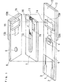
そのような条件を満たしたフィルタを、バイオセンサの電極系および反応試薬系が配置された部分と、試料である血液を供給する部分との間に設置することにより、血球濾過能を有するバイオセンサを構成することが可能である。図9にその一例を示す。図9は反応試薬層を除いた分解斜視図を示している。
【0009】
図9において、ポリエチレンテレフタレートからなる絶縁性基板101上に、スクリーン印刷により銀ペーストを印刷してリード102、103および電極系の下地を形成してある。そして、基板101上に、さらに、樹脂バインダーを含む導電性カーボンペーストを印刷することにより作用極104と対極105を含む電極系を形成し、また、絶縁性ペーストを印刷することにより絶縁層106をそれぞれ形成している。作用極104は、リード102に、また対極105はリード103にそれぞれ接続されている。絶縁層106は、作用極104および対極105の露出部分の面積を一定とし、かつリードを部分的に覆っている。
【0010】
このようにして電極系を形成した絶縁性基板101と、空気孔109を備えたカバー108、スぺーサ107および血球濾過能を有するフィルタ111を、図中一点鎖線で示すような位置関係をもって接着しバイオセンサを作製する。フィルタ111は、カバー108と絶縁性基板101との間に、スペーサ107のスリット110によって形成される試料液供給路に嵌合するよう裁断されたものである。113aは、フィルタ111が絶縁性基板に接触する部分を示している。フィルタ111は、前記の試料液供給路における、作用極104と対極105からなる電極系を覆うことなく、電極系と基板上の試料供給部112との間に設置されている。
【0011】
このような構成のバイオセンサは、試料供給部112上に血液を滴下すると、血液がフィルタ111の試料供給部側の端部からその内へ浸透する。フィルタ内では、血球の浸透速度は液体成分である血漿より遅いので、血漿がフィルタの電極系側端部から浸み出す。そしてこの浸み出した血漿は、酵素等からなり、電極系を覆う位置またはその直上のカバー裏面に担持された反応試薬を溶解しつつ電極系近傍から、さらに空気孔109部分までの試料液供給路全体を満たす。試料液供給路全体が液体で満たされると、フィルタ111内の液体の流動も停止し、その時点で、血球はフィルタの電極系側の端部に到達せず、その位置に留め置かれる。
【0012】
このような、血球濾過の過程を経て、血漿により溶解された反応試薬層と血漿中の測定成分、コレステロールセンサであればコレステロール、との化学反応が生じ、一定時間経過後、電極反応により電流値を測定することにより、血漿中の成分の測定が行われる。
しかし、このようなバイオセンサでは、試料供給部112に滴下された血液の一部が、フィルタ111の試料供給部側の端部から吸収されず、試料液供給路とフィルタ111の接触部分を伝搬し、血球成分を含んだまま反応試薬層まで到達し、その結果、血球または血球内の成分が反応試薬と相互作用し、測定値に誤差を生じさせるという問題があった。
【0013】
このような、フィルタ111と試料液供給路の間隙を血液が伝搬する現象は、フィルタ111と試料液供給路の接触部分を接着剤を用いて接着することにより防止することは可能である。
しかし、用いる接着剤によっては、血液成分の変成をもたらす可能性がある。また、フィルタ111の表面か試料液供給路のいずれかに接着剤を塗布する必要があり、製作工程が複雑になるという問題がある。
【0014】
本発明は、血球等の固形成分を濾過する能力を有するフィルタを備えたバイオセンサを改良して上記問題点を解消することを目的とする。
本発明は、センサに添加された試料がフィルタ内に浸透するが、フィルタを透過した試料液のみが反応試薬層および電極系に到達するようにし、これによって安定した応答性を示すバイオセンサを提供することを目的とする。
【0015】
発明の開示
本発明のバイオセンサは、絶縁性基板、前記基板上に設けられた少なくとも作用極と対極とを有する電極系、前記基板に組み合わされて基板との間に試料供給部から前記電極系に試料液を導くための試料液供給路を形成するカバー部材、少なくとも酸化還元酵素と電子メディエータとを含む反応試薬系、および前記試料液供給路において、電極系と試料供給部の間に設置されたフィルタを具備するバイオセンサであって、前記フィルタの試料供給部側の端部から電極系側の端部までの領域の範囲内において、フィルタ表面を一回り囲む空隙部を有することを特徴とする。
【0016】
前記試料供給部は、好ましい形態においては、前記基板上に設けられ、前記試料液供給路は基板およびカバー部材に沿って配列される。
そのような形態においては、前記フィルタの表面を一回り囲む空隙部は、その幅が0.5mm以上であることが好ましい。前記空隙部の幅が0.5mmより小さいと、試料液供給路を形成する基板および/またはカバー部材とフィルタとの間隙を伝搬した血液が、さらに毛細管現象によってこの空隙部の領域にも及ぶ可能性がある。より好ましくは、空隙部の幅は0.5mmから5.0mmである。5.0mmを越えると、センサに振動が加わったりした場合にフィルタが変形する可能性があり好ましくない。さらに好ましくは1.0mmから3.0mmである。
【0017】
他の好ましい形態において、前記試料供給部は、前記カバー部材に設けられ、前記試料液供給路は試料供給部から重力方向に配列される。この形態においては、フィルタの表面を一回り囲む空隙部の幅は、100μm以上で前記フィルタの厚みより小さいのが好ましい。
ここに用いるフィルタは、三次元的に連なる空隙部を有する多孔体からなり、この多孔体は毛管作用により血液を前記試料供給部側から試料液供給路側へ移動させるが、血漿と血球との流通抵抗の差により血球を濾過する作用を有する。このフィルタには、ガラス繊維、セルロース、パルプなどの好ましくは親水性の繊維からなる不織布、濾紙、その他の多孔質体が用いられる。
【0018】
本発明は、好ましくは酸化還元酵素がコレステロールオキシダーゼであるコレステロールセンサに適用される。
コレステロールセンサにおいては、前記反応試薬系がコレステロールエステル加水分解能を有する酵素を含むことが好ましい。さらに好ましくは、前記コレステロールエステル加水分解能を有する酵素がコレステロールエステラーゼであり、前記反応試薬系が界面活性剤を含むことが好ましい。
前記カバー部材および前記絶縁性基板の一部または全部が透明であることが望ましい。
【0019】
発明を実施するための最良の形態
上記のように、本発明によるバイオセンサは、基板とこれに組み合わせたカバー部材との間に形成された試料液供給路に、基板またはカバー部材側の試料供給部と基板上の電極系との間に設置されたフィルタを具備し、前記フィルタの試料供給部側の端部から電極系側の端部までの領域の範囲内において、フィルタ表面を一回り囲む空隙部を有する。すなわち、フィルタの表面がその全周において試料液供給路を形成する基板およびカバー部材と接触しない領域を設ける。
【0020】
本発明は、ある観点において、絶縁性基板、前記基板上に設けられた少なくとも作用極と対極とを有する電極系、前記基板に組み合わされて基板との間に基板上の試料供給部から前記電極系に試料液を導くための試料液供給路を形成するカバー部材、少なくとも酸化還元酵素と電子メディエータとを含み前記電極系上またはその近傍に設けられた反応試薬系、および前記試料供給路において、電極系と試料供給部の間に設置されたフィルタを具備するバイオセンサであって、前記フィルタの試料供給部側の端部から電極系側の端部までの領域において、フィルタ表面を一回り囲む空隙部を有するバイオセンサである。
【0021】
本発明は、別の観点において、絶縁性基板、前記基板上に設けられた少なくとも作用極と対極とを有する電極系、前記基板上に組み合わされたカバー部材、前記カバー部材と基板との間に形成され、前記カバー部材の試料供給部から基板上の電極系に試料液を導くための試料液供給路、少なくとも酸化還元酵素と電子メディエータとを含み前記電極系上またはその近傍に設けられた反応試薬系、および前記試料供給路において、電極系と試料供給部の間に設置されたフィルタを具備するバイオセンサであって、前記フィルタの試料供給部側の端部から電極系側の端部までの領域において、フィルタ表面を一回り囲む空隙部を有するバイオセンサである。
【0022】
このような構造により、試料供給部に滴下された血液等の試料液は、前記フィルタに吸収され、血球等の固形成分が前記フィルタにより濾過されながら試料液供給路を電極系および反応試薬層の方向に流動する。その結果、血球等の固形成分を濾過された試料液のみが電極系に達する。試料液供給路の試料供給部付近では、フィルタと試料液供給路との接触部に生じる僅かな隙間から、試料液の一部がフィルタに吸収されずに直接試料液供給路内に流入する場合も起こりうる。しかし、そのような試料液は、前記フィルタの表面を一回り囲む空隙部において、それ以上電極系側に進むのを遮断される。従って、血球等の固形成分を含む試料液が、この空隙部を設けた領域より電極系側に向けて、流入することはない。反応試薬層は、試料液供給路において、電極系上またはその近傍に設けるのが好ましい。
【0023】
反応試薬系を構成する酸化還元酵素には、種々のものを用いることができる。例えば、グルコースオキシダ−ゼ、乳酸オキシダーゼ、コレステロールオキシダーゼ等が挙げられる。
血清コレステロール値を測定する場合は、コレステロールオキシダーゼとコレステロールエステル加水分解能を有する酵素を用いる。コレステロールエステル加水分解能を有する酵素には、コレステロールエステラーゼ、リポプロテインリパーゼ等が挙げられる。特に、コレステロールエステラーゼは、適当な界面活性剤を用いることによって、迅速にコレステロールエステルをコレステロールに変化させることができるので都合がよい。
【0024】
コレステロールエステル加水分解能を有する酵素を使用する場合、この酵素の活性を向上させる効果を有する界面活性剤を反応試薬中に含ませると、酵素反応に要する時間を短縮することができて好ましい。
例えば、コレステロールエステラーゼの活性を向上させる界面活性剤には、n−オクチル−β−D−チオグルコシド、ポリエチレングリコールモノドデシルエーテル、コール酸ナトリウム、ドデシル−β−マルトシド、シュークロースモノラウレート、デオキシコール酸ナトリウム、タウロデオキシコール酸ナトリウム、N,N−ビス(3−D−グルコンアミドプロピル)コールアミド、N,N−ビス(3−D−グルコンアミドプロピル)デオキシコールアミド、ポリオキシエチレン−p−t−オクチルフェニルエーテル(「TritonX−100」)などを任意に用いることができる。
【0025】
バイオセンサの電極系を白金などの電気化学的に安定な金属を用いて形成すると、得られる酸化電流値が誤差を含むことがない。しかし、このような金属は高価であるため、使い捨て型のセンサでは、銀ペーストなどを用いて銀電極を形成し、これをカーボンペーストで被覆してカーボン電極を形成し、これら銀・カーボン電極により電極系を形成している。ところが、試料液中に界面活性剤が含有されると、界面活性剤の作用により試料液がカーボン粒子間に浸潤する。その結果、カーボン電極の活性が低下することがある。また、試料液が銀電極に接触する状態になる。このため、この状態で作用極に電圧を印加すると、銀電極が酸化反応を起こして電流を生じ、測定電流値に正の誤差を与えることがある。
【0026】
このような現象を抑制するために、電極系表面を親水性高分子で被覆する方法がある。この親水性高分子は、試料液が導入されると粘調な層となって試料液が電極に接触するのを抑制する。
このような親水性高分子には、カルボキシメチルセルロース、ポリビニルピロリドン、ポリビニルアルコール、エチルセルロース、ヒドロキシプロピルセルロース、ゼラチン、ポリアクリル酸およびその塩、デンプンおよびその誘導体、無水マレイン酸またはその塩のポリマー、ポリアクリルアミド、メタクリレート樹脂、ポリ−2−ヒドロキシエチルメタクリレートなどが挙げられる。
【0027】
上記のような界面活性剤による影響を抑制するには、上記親水性高分子を用いる方法の他、次のような方法がある。すなわち、電極系の試料液に接触する部分をカーボンペーストのみで形成し、導電性確保のために用いる銀ペーストは、絶縁層で被覆された部分にのみ用いるのである。このような印刷電極を用いる場合、上記の親水性高分子層は不要であるが、これらの親水性高分子は、試料液または、試料液と反応試薬の混合液中の蛋白質などが電極表面に吸着して電極反応の活性を低下させるのを防ぐ効果をも有する。従って、このような印刷電極を用いる場合においても、親水性高分子を用いることが好ましい。
【0028】
バイオセンサの電極系を銀およびカーボンで形成する場合は、反応試薬中に、電子メディエータを含有させる。
このような電子メデイエータには、フェリシアン化カリウム、p−ベンゾキノン、フェナジンメトサルフェート、フェロセン誘導体(酸化型)など水溶性で、酵素−電極間の電子移動を媒介しうる化合物を任意に使用できる。
酸化電流の測定方法としては、作用極と対極のみの二電極方式と、参照極を加えた三電極方式があり、三電極方式の方がより正確な測定が可能である。
【0029】
以下に具体的な実施の形態を挙げて、本発明を詳細に説明する。なお、図面は概略を示すものであって、各要素の相対的なサイズは必ずしも正確ではない。
図1は、本発明の一実施形態におけるバイオセンサの分解斜視図であり、図2はその縦断面図である。
【0030】
ポリエチレンテレフタレートからなる絶縁性基板1上に、スクリーン印刷により銀ペーストを印刷してリード2、3および電極系の下地を形成してある。そして、基板1上に、さらに、樹脂バインダーを含む導電性カーボンペーストを印刷することにより作用極4と対極5を含む電極系を形成し、また、絶縁性ペーストを印刷することにより絶縁層6をそれぞれ形成している。作用極4は、リード2に、また対極5はリード3にそれぞれ接続されている。絶縁層6は、作用極4および対極5の露出部分の面積を一定とし、かつリードを部分的に覆っている。
【0031】
このようにして電極系を形成した絶縁性基板1と、空気孔9を備えたカバー8、スぺーサ7および血球濾過能を有するフィルタ11を、図中、一点鎖線で示すような位置関係をもって接着してバイオセンサが作製される。基板1とカバー8との間に、スペーサ7のスリット10により試料液供給路が基板1およびカバー8に沿って形成される。フィルタ11は、この試料液供給路に嵌合する大きさに裁断され、電極系と試料供給部との間に、電極系を覆わないように設置されている。13aおよび13bは、それぞれフィルタ11が絶縁性基板1およびカバー8に接触する部分を示している。
【0032】
フィルタ11の試料供給部12側の端部から電極系側の端部までの領域で、フィルタ表面が、試料液供給路を形成する基板1、スペーサ7およびカバー8に接触しない領域を設けるために、基板1およびスペーサ7には、それぞれ対応する位置に透孔14および15が設けられ、カバー8にはスリット10に連なる2個の切欠部16が設けられている。基板1およびカバー8の透孔14および15を覆うように、それらの外面に蓋17および18が張り付けられている。上記の透孔14および15並びに切欠部16、16によって、フィルタ11の表面を一回り囲む空隙部が形成される。
【0033】
透孔14および15は、それぞれ蓋17および18で閉塞したが、閉塞しなくともその機能は損なわれない。しかし、閉塞しないと、フィルタ11が外部へ露出するので、この部分からの試料液の蒸発により、一旦フィルタを通過して電極系に到達した液体が逆流する可能性がある。そこで、基板およびカバーの透孔を覆うように蓋17および18を設けた。基板およびカバーがかなりな厚さを有していれば、透孔の代わりに凹部を設ければ、蓋17および18は不要である。
【0034】
基板上の試料供給部12に、試料液を滴下し、フィルタ11の試料供給部側の端部に接触させると、試料液はフィルタ11に吸引され、フィルタ11により血球等の固形成分を除去され、血漿は試料液供給路を移動し、センサ内部へ導入される。そして、血漿は、電極系を覆う位置またはその直上のカバー裏面に担持された反応試薬を溶解しながら電極系近傍から、さらに空気孔9の部分までの試料液供給路全体を満たす。試料液供給路全体が液体で満たされると、フィルタ11内の液体の流動も停止し、その時点で、血球はフィルタ11の電極系側の端部に到達せず、その位置に留め置かれる。従って、フィルタ11は、血漿が試料液供給路全体を満たすだけの量が通過してなお血球がフィルタの先端側に達しない程度に、血漿と血球との流通抵抗の差があるように設計される。
【0035】
本実施例では、スリット10により形成される試料液供給路の試料供給部側の端部から空気孔9の外周までの長さは12.5mm、スリット10の幅は2.0mm、スリット10の深さは0.1mmである。
透孔14および15のサイズを(基板の長手方向に直交する方向の寸法)×(基板の長手方向の寸法)で表すと、4.0×3.0mm、同じく切欠部16のサイズは4.0×3.0mmである。基板およびカバーの厚みは各々0.35mm、スペーサの厚みは0.1mmである。従って、上下において0.35mm、左右において2.0mmの厚さを有し、試料液の進行方向の寸法(以下、単に空隙部の幅という)3.0mmの空隙部により、フィルタ11は囲まれていることとなる。この空隙部は、試料供給部12の端部から1mm、電極系の端部から3.0mmの位置にある。前記の寸法は、好ましい実施の形態における1つの例を示すものであって、必ずしも前記の値に限定されるものではない。
【0036】
図2は、組み立てられたバイオセンサの縦断面図である。基板1の電極系上には、親水性高分子層21、およびこれを覆うように電子メディエータ層22が形成されている。スペーサ7のスリット10の部分に形成された試料液供給路には、フィルタ11が配置されている。このフィルタ11は、その端部が電極系に接触していても接触していなくてもよいが、電極系のうち、作用極4に接触してはならない。試料液供給路内において、カバー8の裏面で、フィルタ11の電極系側端部と空気孔9に挟まれた領域に、酵素および界面活性剤からなる層23が形成されている。この層23とフィルタ11の端部が接触している場合、試料液の層23側への流入が行われやすいが、接触していることが必須であるわけではない。
【0037】
図3は本発明の他の実施形態に係るバイオセンサにおけるスペーサとフィルタとの位置関係を示した平面図である。試料液供給路を形成するためのスリット10は、フィルタが嵌合される部分10aと、電極系が存在し、フィルタによって濾過された試料が流入する部分10bとの幅が異なっている。図3では、フィルタが嵌合される部分10aの幅は、電極系を有する部分10bの幅より狭くなっている。
【0038】
図4は、本発明のさらに他の実施形態に係るバイオセンサの縦断面図である。図2と同様の構成であるが、反応試薬の配置が異なっている。この例では、電極系上には親水性高分子層21のみが形成され、カバー8側には、酵素、界面活性剤および電子メディエータを含浸担持した多孔質担体24が、フィルタ11の端部に接触するように、設けられている。
図5は、本発明のさらに他の実施形態に係るバイオセンサの縦断面図、図6はその試薬層を除いた分解斜視図である。
【0039】
絶縁性基板31上には、図1の場合と同様にして、リード32および33、それぞれのリードに接続された作用極34および対極35、ならびに絶縁層36が形成されている。この基板31上には、複数のスペーサ41、43、45、47および49、ならびにカバー52が組み合わされ、スペーサ43とカバー52との間には、フィルタ51がセットされている。カバー52の透孔53が試料供給部を構成し、スペーサ41、43、45、47および49に設けられた透孔42、44、46、48および50が試料液供給路を重力方向に構成している。スペーサ45および49の透孔46および50は、その径をフィルタ51の径より大きくしているので、フィルタ51の周囲には、55および56で表すように、フィルタ51を囲む空隙部が形成される。スペーサ47は、フィルタ51の外周と部分的に接し、フィルタを位置決めする役割をしている。スペーサ41は、前記の試料液供給路の終端部側を大気に開放するための空気孔54を有する。かくして電極系の上方に位置する試料供給部となる透孔53から電極系に至る試料液供給路には毛管作用により試料液が重力方向に導入され、フィルタ51で濾過された血漿が電極系に到達すると、試料液の移動は停止するようになる。
【0040】
ここで、フィルタ51を囲む空隙部55および56の高さを定めるスペーサ49および45の厚みは100μm以上であることが好ましい。スペーサ41は、その透孔42の部分が試料液と試薬との反応の場を提供するものであり、スペーサ41の厚みは100〜200μmが好ましい。このように試料液供給路を重力方向に配置されていることにより、試料が重力によってフィルタを通過するので迅速に反応試薬層に達する。
【0041】
この例では、電極系上に、CMC層61および電子メディータ層62が形成され、スペーサ43の裏面に酵素と界面活性剤を含む層63が形成されている。
図7は、本発明の他の実施形態に係るバイオセンサの縦断面図、図8はその試薬層を除いた分解斜視図である。ここに示すセンサは、スペーサ43の代わりに、不織布などからなる試料液誘導層57を用いた他は図5および6に示すセンサとほぼ同じである。この例では、電極系の上に、CMC層61、および酵素、界面活性剤、および電子メディータを含む層64を設けている。
以下、本発明の実施例を説明する。
【0042】
【実施例】
実施例1
バイオセンサの一例であるコレステロールセンサを作製するために、まず、図1の絶縁性基板1上の電極系上に、親水性高分子であるカルボキシメチルセルロースのナトリウム塩(以下、CMCという。)の0.5wt%水溶液を滴下し、50℃の温風乾燥器中で10分間乾燥させて、CMC層21を形成した。続いて、CMC層21を覆うように、電子メディエータであるフェリシアン化カリウムの水溶液4μl(フェリシアン化カリウム70mM相当)をCMC層上に滴下し、50℃の温風乾燥器中で10分間乾燥させることにより、フェリシアン化カリウム層22を形成した。
【0043】
一方、界面活性剤であるTritonX−100の2wt%エタノール溶液を、カバー8とスペーサ7のスリット10により形成される凹部に2μl滴下し、室温で3分間乾燥させることにより界面活性剤の層を形成した。次に、ノカルジア由来のコレステロールオキシダーゼ(EC1.1.3.6、以下ChODと略す)とシュードモナス由来のコレステロールエステラーゼ(EC.3.1.1.13、以下ChEと略す)を溶解した水溶液に、TritonX−100を添加した。この混合水溶液を、界面活性剤の層上に1.5μl滴下し、液体窒素にて凍結後、梨型フラスコ内に収納して凍結乾燥器中で一晩乾燥させることにより、1ユニット(U)/センサのコレステロールオキシダーゼ、2.5U/センサのコレステロールエステラーゼおよび2wt%の界面活性剤を含む酵素/界面活性剤層23を形成した。続いて、2mm×8mmの長方形に裁断したガラスフィルタ(ADVANTEC社製GC50、厚さ0.19mm)を作用極に接触しないように、図1に示す位置に設置した。
【0044】
試料液供給路のフィルタを設置する位置には、図1に示すような位置に、フィルタ表面が、試料液供給路を形成する絶縁性基板、スペーサおよびカバーに接触しない領域を設けるために、透孔14および15、並びに切欠部16、16を設けた。これらの寸法は、図1に関する上記の説明に記載のとおりである。
試料液として、全血試料20μlを基板1の試料供給部12上へ滴下した。そして、透明な材料で作られたカバー8をとおして目視により、フィルタで濾過された液体が試料液供給路の空気孔9外周部に到達したのを確認してから3分後に、対極を基準にして作用極にアノード方向へ+0.5Vのパルス電圧を印加し、5秒後の電流値を測定した。その結果、血清中のコレステロール濃度に依存した応答を得ることができた。
【0045】
本実施例では、酵素/界面活性剤層23を、凍結乾燥により形成しているが、風乾により形成することも可能である。ただし、その場合は、反応試薬層の溶解性が大幅に悪化するので、濾過された液体が試料液供給路の空気孔9の外周部に到達してから反応が完了するまでに長時間を要する。
【0046】
実施例2
実施例1では、試料液供給路のカバー裏面部に、凍結乾燥により形成した酵素/界面活性剤層23と、基板側の電極系を覆う位置に、風乾により形成したCMC層21およびフェリシアン化カリウム層22とにより反応試薬系を構成した。本実施例では、図4に示すように、フィルタ11の端部に接触するように、酵素、界面活性剤、および電子メディエータを含浸担持した多孔質担体24を設け、これと基板側の電極系を覆う位置に風乾により形成したCMC層21により反応試薬系を形成した。
このように、多孔質担体に反応試薬系を構成する試薬の一部を担持すると、凍結乾燥で担持した場合と同様、反応試薬の試料液への溶解性が向上する。
【0047】
まず、実施例1同様に電極系上に、親水性高分子であるCMCの0.5wt%水溶液を滴下し、50℃の温風乾燥器中で10分間乾燥させて、CMC層21を形成した。
次に、2×4.5mmに裁断したガラス繊維を主成分とするフェルトからなる多孔質担体24を、セルロース系接着剤(セメダイン社製セメダインC)を用いて、フィルタ11の端部に接触するように、試料液供給路のカバー側の図4に示すような位置に接着、固定した。
【0048】
この多孔質担体24に、実施例1と同じコレステロールオキシダーゼ、コレステロールエステラーゼ、フェリシアン化カリウムおよびTritonX−100を水に溶解させた溶液5μlを滴下し、均一に浸透させた後、50℃の温風乾燥器中で15分間乾燥させた。
【0049】
そして、実施例1と同様に、フィルタ11を配置し、前記のカバー部材と基板1を接着し、バイオセンサを作製した。ただし、多孔質担体24の厚みが約0.1〜0.2mm程度あるので、試料液供給路のフィルタ11より電極系側の部分における、基板1とカバー8との間の距離は実施例1の0.1mmより大幅に大きい、0.3mmとした。そこで、フィルタ11に、実施例2で用いたGB100Rを用いた。
このバイオセンサは、全血試料を試料供給部へ滴下してから3分で、コレステロール濃度に依存した応答値を示した。
【0050】
以上の実施例においては、基板1およびカバー8を透明な材料で形成することにより、試料の流入の様子を目視にて確認することを可能にした。
以上の実施例では、試料液供給路を形成するためのスリット10のフィルタが嵌合される部分と、電極系が存在し、フィルタによって濾過された試料が流入する部分との幅は同じであるが、どちらか一方が狭い形状でもよい。そのような例におけるスペーサおよびフィルタの位置関係および形状の一例を図5に示した。
【0051】
反応試薬系を構成する試薬の配置および担持方法については、反応試薬系を構成する試薬が試料液に迅速に溶解し、酵素反応が円滑に進行する要件を満たしている限り、本実施例に示した条件に限定されるものではない。
【0052】
産業上の利用の可能性
上記のように、本発明によれば、血球などの固形成分を含む試料液に対しても電極系あるいは反応試薬系にこれらの固形成分が接触するのを防ぐことができることにより、精度の高い測定が可能であり、応答値のばらつきが少ないバイオセンサが得られる。
【図面の簡単な説明】
【図1】 本発明の一実施の形態に係るバイオセンサの反応試薬を除いた分解斜視図である。
【図2】 同バイオセンサの縦断面図である。
【図3】 本発明の他の実施の形態に係るバイオセンサの要部の平面図である。
【図4】 本発明のさらに他の実施の形態に係るバイオセンサの縦断面図である。
【図5】 本発明のさらに他の実施の形態に係るバイオセンサの縦断面図である。
【図6】 同バイオセンサの分解斜視図である。
【図7】 本発明のさらに他の実施の形態に係るバイオセンサの縦断面図である。
【図8】 同バイオセンサの分解斜視図である。
【図9】 従来例のバイオセンサの反応試薬層を除いた分解斜視図である。[0001]
Technical field
The present invention relates to a biosensor that can easily perform rapid and highly accurate quantification of a measurement object in a sample.
[0002]
Background art
Conventionally, the following biosensor has been proposed as a method for easily quantifying a specific component in a sample without diluting or stirring the sample solution (Japanese Patent Laid-Open No. 2-062952).
In this biosensor, an electrode system including a measurement electrode, a working electrode, a counter electrode, and a reference electrode is formed on an insulating substrate by a method such as screen printing, and a hydrophilic polymer, an oxidoreductase, and a reference electrode are formed on the electrode system. An enzyme reaction layer containing an electron mediator is formed. A buffering agent is added to the enzyme reaction layer as necessary.
[0003]
When a sample solution containing a substrate is dropped onto the enzyme reaction layer of the biosensor produced in this way, the enzyme reaction layer dissolves and the enzyme and the substrate react, and the electron mediator is reduced accordingly. After the completion of the enzyme reaction, the reduced electron mediator is electrochemically oxidized, and the substrate concentration in the sample solution can be determined from the oxidation current value obtained at this time.
Such a biosensor can in principle measure various substances by selecting an enzyme that uses the substance to be measured as a substrate. For example, if glucose oxidase is used as the oxidoreductase, a biosensor that measures glucose concentration in blood can be constructed. This sensor is widely used as a glucose sensor. Further, if cholesterol oxidase is used, a biosensor for measuring cholesterol in serum can be constructed.
[0004]
Usually, the serum cholesterol level used as a diagnostic guide is the sum of the concentrations of cholesterol and cholesterol ester. Cholesterol esters cannot be a substrate for oxidation reaction by cholesterol oxidase. Therefore, in order to measure serum cholesterol level as a diagnostic guideline, a process of changing cholesterol ester to cholesterol is required. Cholesterol esterase is known as an enzyme that catalyzes this process.
By using a biosensor containing the cholesterol esterase and cholesterol oxidase in the enzyme reaction layer, the total cholesterol concentration in the serum can be measured.
[0005]
However, for example, the measurement of cholesterol can be influenced by cholesterol present in the cell membrane. Further, the cholesterol esterase in the reaction reagent is preferably allowed to coexist with a surfactant in order to increase the reactivity. Surfactants often destroy cell membranes, so intracellular substances can directly or indirectly affect enzymatic or electrode reactions. For this reason, in the cholesterol sensor, the enzyme reaction and the subsequent electrode reaction are preferably performed in plasma or serum. In addition to the cholesterol sensor, the presence of blood cells in the blood may affect the response value. Ideally, it is desirable that the enzyme reaction and the electrode reaction be performed in a solution that does not contain blood cells.
[0006]
Centrifugation is well known as a method for separating plasma or serum from whole blood. However, the method using centrifugation is time consuming and complicated.
U.S. Pat. No. 3,607,092 discloses a membrane for testing blood. This membrane has a thin film layer that is permeable to a solution but impermeable to solids such as blood cells and macromolecules such as proteins. It is possible to remove blood cells with this thin film. However, since such a thin film accumulates solid components with the passage of blood, a thin film layer having a large area is required to obtain an amount of filtrate necessary for the reaction of the biosensor. Therefore, the thin film is not necessarily suitable.
[0007]
U.S. Pat. No. 4,477,575 discloses an apparatus and method for separating serum by passing whole blood through a glass fiber filter. Such a method of separating serum from whole blood using a filter made of fiber or porous material can be applied to the biosensor. However, this method does not hold blood cells with a filter, but simply delays the flow to separate blood cells and plasma. Therefore, in order to apply this method to the above-described biosensor, it is necessary to obtain more plasma or serum filtered by the filter while blood cells do not flow out of the filter than the amount necessary for the reaction of the biosensor. For this purpose, the length of the blood flow direction in the filter must be set so as to satisfy this condition.
[0008]
A biosensor having blood cell filtration ability by installing a filter satisfying such conditions between a part where the electrode system and reaction reagent system of the biosensor are arranged and a part supplying blood as a sample Can be configured. An example is shown in FIG. FIG. 9 shows an exploded perspective view with the reaction reagent layer removed.
[0009]
In FIG. 9, a silver paste is printed by screen printing on an
[0010]
The
[0011]
In the biosensor having such a configuration, when blood is dropped onto the
[0012]
Through such a blood cell filtration process, a chemical reaction occurs between the reaction reagent layer dissolved in plasma and the measurement component in plasma, or cholesterol in the case of a cholesterol sensor. By measuring this, the components in plasma are measured.
However, in such a biosensor, a part of the blood dropped on the
[0013]
Such a phenomenon in which blood propagates through the gap between the
However, depending on the adhesive used, there is a possibility of degeneration of blood components. Further, it is necessary to apply an adhesive to either the surface of the
[0014]
An object of the present invention is to improve the biosensor provided with a filter having the ability to filter solid components such as blood cells and to solve the above problems.
The present invention provides a biosensor exhibiting stable responsiveness by allowing a sample added to the sensor to penetrate into the filter but allowing only the sample liquid that has passed through the filter to reach the reaction reagent layer and the electrode system. The purpose is to do.
[0015]
Disclosure of the invention
The biosensor of the present invention includes an insulating substrate, an electrode system having at least a working electrode and a counter electrode provided on the substrate, a sample solution from the sample supply unit to the electrode system between the substrate and the substrate. A cover member that forms a sample solution supply path for guiding the reaction, a reaction reagent system including at least an oxidoreductase and an electron mediator, and a filter installed between the electrode system and the sample supply unit in the sample solution supply path The biosensor is provided with an air gap that surrounds the filter surface in a region from the end on the sample supply side to the end on the electrode system side of the filter.
[0016]
In a preferred embodiment, the sample supply unit is provided on the substrate, and the sample solution supply path is arranged along the substrate and the cover member.
In such a form, it is preferable that the space | gap part surrounding the surface of the said filter is 0.5 mm or more in width. When the width of the gap is smaller than 0.5 mm, the blood that has propagated through the gap between the substrate and / or the cover member and the filter forming the sample liquid supply path may further reach the gap area by capillary action. There is sex. More preferably, the width of the gap is 0.5 mm to 5.0 mm. If it exceeds 5.0 mm, the filter may be deformed when vibration is applied to the sensor, which is not preferable. More preferably, it is 1.0 mm to 3.0 mm.
[0017]
In another preferred embodiment, the sample supply unit is provided in the cover member, and the sample solution supply path is arranged in the direction of gravity from the sample supply unit. In this embodiment, it is preferable that the width of the air gap surrounding the surface of the filter is 100 μm or more and smaller than the thickness of the filter.
The filter used here is composed of a porous body having three-dimensionally connected voids, and this porous body moves blood from the sample supply part side to the sample liquid supply path side by capillary action. It has the effect of filtering blood cells by the difference in resistance. For this filter, non-woven fabric, filter paper, and other porous materials preferably made of hydrophilic fibers such as glass fiber, cellulose, and pulp are used.
[0018]
The present invention is preferably applied to a cholesterol sensor in which the oxidoreductase is cholesterol oxidase.
In the cholesterol sensor, it is preferable that the reaction reagent system includes an enzyme having a cholesterol ester hydrolyzing ability. More preferably, the enzyme having the ability to hydrolyze cholesterol ester is cholesterol esterase, and the reaction reagent system preferably contains a surfactant.
It is desirable that a part or all of the cover member and the insulating substrate are transparent.
[0019]
BEST MODE FOR CARRYING OUT THE INVENTION
As described above, the biosensor according to the present invention includes a sample solution supply path formed between the substrate and the cover member combined therewith, and the substrate or the sample supply unit on the cover member side and the electrode system on the substrate. The filter is provided in between, and has a gap that surrounds the filter surface in a region from the end on the sample supply side to the end on the electrode system side of the filter. That is, a region where the surface of the filter does not come into contact with the substrate and the cover member that form the sample solution supply path is provided in the entire periphery.
[0020]
In one aspect, the present invention provides an insulating substrate, an electrode system having at least a working electrode and a counter electrode provided on the substrate, and the electrode from the sample supply unit on the substrate in combination with the substrate. A cover member that forms a sample solution supply path for introducing the sample solution into the system, a reaction reagent system that includes at least an oxidoreductase and an electron mediator and is provided on or near the electrode system, and the sample supply channel, A biosensor including a filter installed between an electrode system and a sample supply unit, and surrounds the filter surface in a region from an end on the sample supply unit side to an end on the electrode system side of the filter. A biosensor having a gap.
[0021]
In another aspect, the present invention provides an insulating substrate, an electrode system having at least a working electrode and a counter electrode provided on the substrate, a cover member combined on the substrate, and between the cover member and the substrate. A sample solution supply path for introducing a sample solution from the sample supply portion of the cover member to the electrode system on the substrate, a reaction provided on or near the electrode system, including at least an oxidoreductase and an electron mediator In the reagent system and the sample supply path, a biosensor comprising a filter installed between the electrode system and the sample supply unit, from an end on the sample supply side to an end on the electrode system side of the filter In this region, the biosensor has a void that surrounds the filter surface.
[0022]
With such a structure, the sample liquid such as blood dropped on the sample supply unit is absorbed by the filter, and the solid component such as blood cells is filtered by the filter while the sample liquid supply path is formed between the electrode system and the reaction reagent layer. Flow in the direction. As a result, only the sample solution from which solid components such as blood cells have been filtered reaches the electrode system. In the vicinity of the sample supply part of the sample liquid supply path, when a part of the sample liquid flows directly into the sample liquid supply path without being absorbed by the filter from a slight gap generated at the contact portion between the filter and the sample liquid supply path Can also happen. However, such a sample solution is blocked from proceeding further to the electrode system side in a gap surrounding the surface of the filter. Therefore, the sample liquid containing solid components such as blood cells does not flow in toward the electrode system side from the region where the gap is provided. The reaction reagent layer is preferably provided on or near the electrode system in the sample solution supply path.
[0023]
Various oxidoreductases constituting the reaction reagent system can be used. For example, glucose oxidase, lactate oxidase, cholesterol oxidase and the like can be mentioned.
When measuring serum cholesterol levels, an enzyme having cholesterol oxidase and cholesterol ester hydrolyzing ability is used. Examples of the enzyme having the ability to hydrolyze cholesterol ester include cholesterol esterase and lipoprotein lipase. In particular, cholesterol esterase is advantageous because it can rapidly convert cholesterol ester to cholesterol by using an appropriate surfactant.
[0024]
When using an enzyme having cholesterol ester hydrolyzing ability, it is preferable to include a surfactant having an effect of improving the activity of the enzyme in the reaction reagent because the time required for the enzyme reaction can be shortened.
For example, surfactants that improve the activity of cholesterol esterase include n-octyl-β-D-thioglucoside, polyethylene glycol monododecyl ether, sodium cholate, dodecyl-β-maltoside, sucrose monolaurate, deoxychol Acid sodium, sodium taurodeoxycholate, N, N-bis (3-D-gluconamidopropyl) coleamide, N, N-bis (3-D-gluconamidopropyl) deoxycholamide, polyoxyethylene-p- t-Octylphenyl ether (“Triton X-100”) and the like can be arbitrarily used.
[0025]
When the electrode system of the biosensor is formed using an electrochemically stable metal such as platinum, the obtained oxidation current value does not include an error. However, since such a metal is expensive, in a disposable sensor, a silver electrode is formed using a silver paste or the like, and this is covered with a carbon paste to form a carbon electrode. An electrode system is formed. However, when a surfactant is contained in the sample solution, the sample solution infiltrates between the carbon particles by the action of the surfactant. As a result, the activity of the carbon electrode may decrease. In addition, the sample solution comes into contact with the silver electrode. For this reason, when a voltage is applied to the working electrode in this state, the silver electrode causes an oxidation reaction to generate a current, which may give a positive error to the measured current value.
[0026]
In order to suppress such a phenomenon, there is a method of coating the surface of the electrode system with a hydrophilic polymer. The hydrophilic polymer becomes a viscous layer when the sample solution is introduced, and suppresses the sample solution from contacting the electrode.
Such hydrophilic polymers include carboxymethyl cellulose, polyvinyl pyrrolidone, polyvinyl alcohol, ethyl cellulose, hydroxypropyl cellulose, gelatin, polyacrylic acid and its salts, starch and its derivatives, maleic anhydride or its salt polymers, polyacrylamide , Methacrylate resin, poly-2-hydroxyethyl methacrylate, and the like.
[0027]
In order to suppress the influence of the surfactant as described above, there are the following methods in addition to the method using the hydrophilic polymer. That is, the portion of the electrode system that comes into contact with the sample solution is formed only from the carbon paste, and the silver paste used for ensuring conductivity is used only for the portion covered with the insulating layer. When such a printed electrode is used, the hydrophilic polymer layer described above is not necessary. However, these hydrophilic polymers have a sample solution or a protein in a mixed solution of the sample solution and the reaction reagent on the electrode surface. It also has the effect of preventing the activity of the electrode reaction from being reduced by adsorption. Accordingly, even when such a printed electrode is used, it is preferable to use a hydrophilic polymer.
[0028]
When the biosensor electrode system is formed of silver and carbon, an electron mediator is included in the reaction reagent.
As such an electron mediator, a water-soluble compound such as potassium ferricyanide, p-benzoquinone, phenazine methosulphate, and a ferrocene derivative (oxidized form) that can mediate electron transfer between an enzyme and an electrode can be arbitrarily used.
As a method for measuring the oxidation current, there are a two-electrode method using only a working electrode and a counter electrode, and a three-electrode method including a reference electrode, and the three-electrode method enables more accurate measurement.
[0029]
Hereinafter, the present invention will be described in detail with reference to specific embodiments. Note that the drawings are schematic and the relative sizes of the elements are not necessarily accurate.
FIG. 1 is an exploded perspective view of a biosensor according to an embodiment of the present invention, and FIG. 2 is a longitudinal sectional view thereof.
[0030]
On the insulating substrate 1 made of polyethylene terephthalate, silver paste is printed by screen printing to form the
[0031]
Thus, the insulating substrate 1 on which the electrode system is formed, the
[0032]
In order to provide a region where the filter surface does not contact the substrate 1, the
[0033]
The through holes 14 and 15 are closed by the
[0034]
When the sample solution is dropped onto the
[0035]
In the present embodiment, the length from the end on the sample supply part side of the sample liquid supply path formed by the
When the size of the through
[0036]
FIG. 2 is a longitudinal sectional view of the assembled biosensor. On the electrode system of the substrate 1, a
[0037]
FIG. 3 is a plan view showing a positional relationship between a spacer and a filter in a biosensor according to another embodiment of the present invention. In the
[0038]
FIG. 4 is a longitudinal sectional view of a biosensor according to still another embodiment of the present invention. Although it is the same structure as FIG. 2, arrangement | positioning of the reaction reagent differs. In this example, only the
FIG. 5 is a longitudinal sectional view of a biosensor according to still another embodiment of the present invention, and FIG. 6 is an exploded perspective view excluding the reagent layer.
[0039]
On the insulating
[0040]
Here, the thickness of the
[0041]
In this example, a
FIG. 7 is a longitudinal sectional view of a biosensor according to another embodiment of the present invention, and FIG. 8 is an exploded perspective view excluding the reagent layer. The sensor shown here is almost the same as the sensor shown in FIGS. 5 and 6 except that a sample
Examples of the present invention will be described below.
[0042]
【Example】
Example 1
In order to produce a cholesterol sensor which is an example of a biosensor, first, a sodium salt of carboxymethyl cellulose (hereinafter referred to as CMC), which is a hydrophilic polymer, is formed on the electrode system on the insulating substrate 1 of FIG. A 5 wt% aqueous solution was dropped and dried in a warm air dryer at 50 ° C. for 10 minutes to form the
[0043]
Meanwhile, a surfactant layer is formed by dropping 2 μl of a 2 wt% ethanol solution of Triton X-100, which is a surfactant, into a recess formed by the
[0044]
In order to provide a region where the filter surface is not in contact with the insulating substrate, the spacer and the cover forming the sample liquid supply path at the position as shown in FIG.
As a sample solution, 20 μl of a whole blood sample was dropped onto the
[0045]
In this embodiment, the enzyme / surfactant layer 23 is formed by freeze-drying, but it can also be formed by air-drying. However, in this case, the solubility of the reaction reagent layer is greatly deteriorated, so it takes a long time for the reaction to be completed after the filtered liquid reaches the outer periphery of the
[0046]
Example 2
In Example 1, the enzyme / surfactant layer 23 formed by lyophilization on the back surface of the cover of the sample solution supply path, and the
As described above, when a part of the reagent constituting the reaction reagent system is supported on the porous carrier, the solubility of the reaction reagent in the sample solution is improved as in the case of supporting by lyophilization.
[0047]
First, a 0.5 wt% aqueous solution of CMC, which is a hydrophilic polymer, was dropped on the electrode system in the same manner as in Example 1, and dried in a hot air drier at 50 ° C. for 10 minutes to form a
Next, the
[0048]
To this
[0049]
And the
This biosensor showed a response value depending on the
[0050]
In the above embodiment, the substrate 1 and the
In the above embodiment, the width of the portion where the filter of the
[0051]
The arrangement and loading method of the reagents constituting the reaction reagent system are shown in this example as long as the reagents constituting the reaction reagent system rapidly dissolve in the sample solution and meet the requirements for smooth enzymatic reaction. The conditions are not limited.
[0052]
Industrial applicability
As described above, according to the present invention, it is possible to prevent the contact of these solid components with the electrode system or the reaction reagent system even for a sample solution containing solid components such as blood cells. And a biosensor with little variation in response value can be obtained.
[Brief description of the drawings]
FIG. 1 is an exploded perspective view of a biosensor according to an embodiment of the present invention except for a reaction reagent.
FIG. 2 is a longitudinal sectional view of the biosensor.
FIG. 3 is a plan view of a main part of a biosensor according to another embodiment of the present invention.
FIG. 4 is a longitudinal sectional view of a biosensor according to still another embodiment of the present invention.
FIG. 5 is a longitudinal sectional view of a biosensor according to still another embodiment of the present invention.
FIG. 6 is an exploded perspective view of the biosensor.
FIG. 7 is a longitudinal sectional view of a biosensor according to still another embodiment of the present invention.
FIG. 8 is an exploded perspective view of the biosensor.
FIG. 9 is an exploded perspective view of a conventional biosensor excluding a reaction reagent layer.
Claims (14)
Applications Claiming Priority (2)
| Application Number | Priority Date | Filing Date | Title |
|---|---|---|---|
| JP2000232385 | 2000-07-31 | ||
| PCT/JP2001/006472 WO2002010735A1 (en) | 2000-07-31 | 2001-07-26 | Biosensor |
Publications (1)
| Publication Number | Publication Date |
|---|---|
| JP4184074B2 true JP4184074B2 (en) | 2008-11-19 |
Family
ID=18725079
Family Applications (1)
| Application Number | Title | Priority Date | Filing Date |
|---|---|---|---|
| JP2002516612A Expired - Fee Related JP4184074B2 (en) | 2000-07-31 | 2001-07-26 | Biosensor |
Country Status (7)
| Country | Link |
|---|---|
| US (1) | US6776888B2 (en) |
| EP (1) | EP1223425B1 (en) |
| JP (1) | JP4184074B2 (en) |
| CN (1) | CN1180259C (en) |
| DE (1) | DE60137111D1 (en) |
| ES (1) | ES2317947T3 (en) |
| WO (1) | WO2002010735A1 (en) |
Cited By (2)
| Publication number | Priority date | Publication date | Assignee | Title |
|---|---|---|---|---|
| KR101964885B1 (en) * | 2018-04-25 | 2019-04-02 | (주) 비비비 | Blood analyzer |
| WO2022119086A1 (en) * | 2020-12-02 | 2022-06-09 | 동우 화인켐 주식회사 | Patch-type biosensor |
Families Citing this family (120)
| Publication number | Priority date | Publication date | Assignee | Title |
|---|---|---|---|---|
| US6036924A (en) | 1997-12-04 | 2000-03-14 | Hewlett-Packard Company | Cassette of lancet cartridges for sampling blood |
| US8071384B2 (en) | 1997-12-22 | 2011-12-06 | Roche Diagnostics Operations, Inc. | Control and calibration solutions and methods for their use |
| US6391005B1 (en) | 1998-03-30 | 2002-05-21 | Agilent Technologies, Inc. | Apparatus and method for penetration with shaft having a sensor for sensing penetration depth |
| US20050103624A1 (en) | 1999-10-04 | 2005-05-19 | Bhullar Raghbir S. | Biosensor and method of making |
| US6645359B1 (en) * | 2000-10-06 | 2003-11-11 | Roche Diagnostics Corporation | Biosensor |
| US8641644B2 (en) | 2000-11-21 | 2014-02-04 | Sanofi-Aventis Deutschland Gmbh | Blood testing apparatus having a rotatable cartridge with multiple lancing elements and testing means |
| EP1404233B1 (en) | 2001-06-12 | 2009-12-02 | Pelikan Technologies Inc. | Self optimizing lancing device with adaptation means to temporal variations in cutaneous properties |
| WO2002100461A2 (en) | 2001-06-12 | 2002-12-19 | Pelikan Technologies, Inc. | Method and apparatus for improving success rate of blood yield from a fingerstick |
| US9427532B2 (en) | 2001-06-12 | 2016-08-30 | Sanofi-Aventis Deutschland Gmbh | Tissue penetration device |
| DE60238914D1 (en) | 2001-06-12 | 2011-02-24 | Pelikan Technologies Inc | INTEGRATED BLOOD SAMPLE ANALYSIS SYSTEM WITH MULTI-USE SAMPLING MODULE |
| US7041068B2 (en) | 2001-06-12 | 2006-05-09 | Pelikan Technologies, Inc. | Sampling module device and method |
| WO2002100460A2 (en) | 2001-06-12 | 2002-12-19 | Pelikan Technologies, Inc. | Electric lancet actuator |
| US9795747B2 (en) | 2010-06-02 | 2017-10-24 | Sanofi-Aventis Deutschland Gmbh | Methods and apparatus for lancet actuation |
| US9226699B2 (en) | 2002-04-19 | 2016-01-05 | Sanofi-Aventis Deutschland Gmbh | Body fluid sampling module with a continuous compression tissue interface surface |
| DE60234597D1 (en) | 2001-06-12 | 2010-01-14 | Pelikan Technologies Inc | DEVICE AND METHOD FOR REMOVING BLOOD SAMPLES |
| US8337419B2 (en) | 2002-04-19 | 2012-12-25 | Sanofi-Aventis Deutschland Gmbh | Tissue penetration device |
| US7749174B2 (en) | 2001-06-12 | 2010-07-06 | Pelikan Technologies, Inc. | Method and apparatus for lancet launching device intergrated onto a blood-sampling cartridge |
| US7981056B2 (en) | 2002-04-19 | 2011-07-19 | Pelikan Technologies, Inc. | Methods and apparatus for lancet actuation |
| US7344507B2 (en) | 2002-04-19 | 2008-03-18 | Pelikan Technologies, Inc. | Method and apparatus for lancet actuation |
| US7344894B2 (en) | 2001-10-16 | 2008-03-18 | Agilent Technologies, Inc. | Thermal regulation of fluidic samples within a diagnostic cartridge |
| CN1498344A (en) | 2001-11-14 | 2004-05-19 | 松下电器产业株式会社 | Biosensor |
| EP1452857A4 (en) * | 2001-11-14 | 2006-05-24 | Matsushita Electric Ind Co Ltd | Biosensor |
| EP1482307B1 (en) * | 2002-03-01 | 2007-10-03 | Matsushita Electric Industrial Co., Ltd. | Biosensor |
| US8360992B2 (en) | 2002-04-19 | 2013-01-29 | Sanofi-Aventis Deutschland Gmbh | Method and apparatus for penetrating tissue |
| US7708701B2 (en) | 2002-04-19 | 2010-05-04 | Pelikan Technologies, Inc. | Method and apparatus for a multi-use body fluid sampling device |
| US7331931B2 (en) | 2002-04-19 | 2008-02-19 | Pelikan Technologies, Inc. | Method and apparatus for penetrating tissue |
| US7244265B2 (en) | 2002-04-19 | 2007-07-17 | Pelikan Technologies, Inc. | Method and apparatus for penetrating tissue |
| US9795334B2 (en) | 2002-04-19 | 2017-10-24 | Sanofi-Aventis Deutschland Gmbh | Method and apparatus for penetrating tissue |
| US7563232B2 (en) | 2002-04-19 | 2009-07-21 | Pelikan Technologies, Inc. | Method and apparatus for penetrating tissue |
| US7909778B2 (en) | 2002-04-19 | 2011-03-22 | Pelikan Technologies, Inc. | Method and apparatus for penetrating tissue |
| US7547287B2 (en) | 2002-04-19 | 2009-06-16 | Pelikan Technologies, Inc. | Method and apparatus for penetrating tissue |
| US9314194B2 (en) | 2002-04-19 | 2016-04-19 | Sanofi-Aventis Deutschland Gmbh | Tissue penetration device |
| US8579831B2 (en) | 2002-04-19 | 2013-11-12 | Sanofi-Aventis Deutschland Gmbh | Method and apparatus for penetrating tissue |
| US8784335B2 (en) | 2002-04-19 | 2014-07-22 | Sanofi-Aventis Deutschland Gmbh | Body fluid sampling device with a capacitive sensor |
| US7892183B2 (en) | 2002-04-19 | 2011-02-22 | Pelikan Technologies, Inc. | Method and apparatus for body fluid sampling and analyte sensing |
| US7297122B2 (en) | 2002-04-19 | 2007-11-20 | Pelikan Technologies, Inc. | Method and apparatus for penetrating tissue |
| WO2003088824A2 (en) | 2002-04-19 | 2003-10-30 | Pelikan Technologies, Inc. | Device and method for variable speed lancet |
| US7232451B2 (en) | 2002-04-19 | 2007-06-19 | Pelikan Technologies, Inc. | Method and apparatus for penetrating tissue |
| US7491178B2 (en) | 2002-04-19 | 2009-02-17 | Pelikan Technologies, Inc. | Method and apparatus for penetrating tissue |
| US8221334B2 (en) | 2002-04-19 | 2012-07-17 | Sanofi-Aventis Deutschland Gmbh | Method and apparatus for penetrating tissue |
| US7976476B2 (en) | 2002-04-19 | 2011-07-12 | Pelikan Technologies, Inc. | Device and method for variable speed lancet |
| US7141058B2 (en) | 2002-04-19 | 2006-11-28 | Pelikan Technologies, Inc. | Method and apparatus for a body fluid sampling device using illumination |
| US8267870B2 (en) | 2002-04-19 | 2012-09-18 | Sanofi-Aventis Deutschland Gmbh | Method and apparatus for body fluid sampling with hybrid actuation |
| US7582099B2 (en) | 2002-04-19 | 2009-09-01 | Pelikan Technologies, Inc | Method and apparatus for penetrating tissue |
| US7901362B2 (en) | 2002-04-19 | 2011-03-08 | Pelikan Technologies, Inc. | Method and apparatus for penetrating tissue |
| US7374544B2 (en) | 2002-04-19 | 2008-05-20 | Pelikan Technologies, Inc. | Method and apparatus for penetrating tissue |
| US7524293B2 (en) | 2002-04-19 | 2009-04-28 | Pelikan Technologies, Inc. | Method and apparatus for penetrating tissue |
| US7371247B2 (en) | 2002-04-19 | 2008-05-13 | Pelikan Technologies, Inc | Method and apparatus for penetrating tissue |
| US7648468B2 (en) | 2002-04-19 | 2010-01-19 | Pelikon Technologies, Inc. | Method and apparatus for penetrating tissue |
| US7485128B2 (en) | 2002-04-19 | 2009-02-03 | Pelikan Technologies, Inc. | Method and apparatus for penetrating tissue |
| US7229458B2 (en) | 2002-04-19 | 2007-06-12 | Pelikan Technologies, Inc. | Method and apparatus for penetrating tissue |
| US7674232B2 (en) | 2002-04-19 | 2010-03-09 | Pelikan Technologies, Inc. | Method and apparatus for penetrating tissue |
| US9248267B2 (en) | 2002-04-19 | 2016-02-02 | Sanofi-Aventis Deustchland Gmbh | Tissue penetration device |
| US7717863B2 (en) | 2002-04-19 | 2010-05-18 | Pelikan Technologies, Inc. | Method and apparatus for penetrating tissue |
| US7291117B2 (en) | 2002-04-19 | 2007-11-06 | Pelikan Technologies, Inc. | Method and apparatus for penetrating tissue |
| US7410468B2 (en) | 2002-04-19 | 2008-08-12 | Pelikan Technologies, Inc. | Method and apparatus for penetrating tissue |
| US8372016B2 (en) | 2002-04-19 | 2013-02-12 | Sanofi-Aventis Deutschland Gmbh | Method and apparatus for body fluid sampling and analyte sensing |
| US8702624B2 (en) | 2006-09-29 | 2014-04-22 | Sanofi-Aventis Deutschland Gmbh | Analyte measurement device with a single shot actuator |
| CN1467496A (en) * | 2002-06-03 | 2004-01-14 | 松下电器产业株式会社 | biological sensor |
| JP3878993B2 (en) * | 2002-10-31 | 2007-02-07 | アークレイ株式会社 | Analysis tool |
| US8574895B2 (en) | 2002-12-30 | 2013-11-05 | Sanofi-Aventis Deutschland Gmbh | Method and apparatus using optical techniques to measure analyte levels |
| CN1701229A (en) * | 2003-04-28 | 2005-11-23 | 松下电器产业株式会社 | Filter and biosensor with the same |
| EP1596190B1 (en) * | 2003-05-15 | 2014-01-29 | Panasonic Corporation | Sensor |
| US8153081B2 (en) * | 2003-05-29 | 2012-04-10 | Bayer Healthcare Llc | Test sensor and method for manufacturing the same |
| DE602004028463D1 (en) | 2003-05-30 | 2010-09-16 | Pelikan Technologies Inc | METHOD AND DEVICE FOR INJECTING LIQUID |
| ES2490740T3 (en) | 2003-06-06 | 2014-09-04 | Sanofi-Aventis Deutschland Gmbh | Apparatus for blood fluid sampling and analyte detection |
| KR100554649B1 (en) * | 2003-06-09 | 2006-02-24 | 주식회사 아이센스 | Electrochemical Biosensor |
| WO2006001797A1 (en) | 2004-06-14 | 2006-01-05 | Pelikan Technologies, Inc. | Low pain penetrating |
| EP1635700B1 (en) | 2003-06-13 | 2016-03-09 | Sanofi-Aventis Deutschland GmbH | Apparatus for a point of care device |
| US7452457B2 (en) | 2003-06-20 | 2008-11-18 | Roche Diagnostics Operations, Inc. | System and method for analyte measurement using dose sufficiency electrodes |
| US7645373B2 (en) | 2003-06-20 | 2010-01-12 | Roche Diagnostic Operations, Inc. | System and method for coding information on a biosensor test strip |
| US7645421B2 (en) | 2003-06-20 | 2010-01-12 | Roche Diagnostics Operations, Inc. | System and method for coding information on a biosensor test strip |
| US7604721B2 (en) | 2003-06-20 | 2009-10-20 | Roche Diagnostics Operations, Inc. | System and method for coding information on a biosensor test strip |
| US7597793B2 (en) | 2003-06-20 | 2009-10-06 | Roche Operations Ltd. | System and method for analyte measurement employing maximum dosing time delay |
| US8679853B2 (en) | 2003-06-20 | 2014-03-25 | Roche Diagnostics Operations, Inc. | Biosensor with laser-sealed capillary space and method of making |
| US8058077B2 (en) | 2003-06-20 | 2011-11-15 | Roche Diagnostics Operations, Inc. | Method for coding information on a biosensor test strip |
| US8206565B2 (en) | 2003-06-20 | 2012-06-26 | Roche Diagnostics Operation, Inc. | System and method for coding information on a biosensor test strip |
| US7718439B2 (en) | 2003-06-20 | 2010-05-18 | Roche Diagnostics Operations, Inc. | System and method for coding information on a biosensor test strip |
| US8148164B2 (en) | 2003-06-20 | 2012-04-03 | Roche Diagnostics Operations, Inc. | System and method for determining the concentration of an analyte in a sample fluid |
| US8071030B2 (en) | 2003-06-20 | 2011-12-06 | Roche Diagnostics Operations, Inc. | Test strip with flared sample receiving chamber |
| HUE039852T2 (en) | 2003-06-20 | 2019-02-28 | Hoffmann La Roche | Method and reagent for producing narrow, homogenous reagent strips |
| US8282576B2 (en) | 2003-09-29 | 2012-10-09 | Sanofi-Aventis Deutschland Gmbh | Method and apparatus for an improved sample capture device |
| US9351680B2 (en) | 2003-10-14 | 2016-05-31 | Sanofi-Aventis Deutschland Gmbh | Method and apparatus for a variable user interface |
| US7822454B1 (en) | 2005-01-03 | 2010-10-26 | Pelikan Technologies, Inc. | Fluid sampling device with improved analyte detecting member configuration |
| EP1706026B1 (en) | 2003-12-31 | 2017-03-01 | Sanofi-Aventis Deutschland GmbH | Method and apparatus for improving fluidic flow and sample capture |
| US7622026B2 (en) * | 2004-03-02 | 2009-11-24 | Panasonic Corporation | Biosensor |
| US8828203B2 (en) | 2004-05-20 | 2014-09-09 | Sanofi-Aventis Deutschland Gmbh | Printable hydrogels for biosensors |
| US9775553B2 (en) | 2004-06-03 | 2017-10-03 | Sanofi-Aventis Deutschland Gmbh | Method and apparatus for a fluid sampling device |
| EP1765194A4 (en) | 2004-06-03 | 2010-09-29 | Pelikan Technologies Inc | Method and apparatus for a fluid sampling device |
| US7556723B2 (en) | 2004-06-18 | 2009-07-07 | Roche Diagnostics Operations, Inc. | Electrode design for biosensor |
| US7569126B2 (en) | 2004-06-18 | 2009-08-04 | Roche Diagnostics Operations, Inc. | System and method for quality assurance of a biosensor test strip |
| US8652831B2 (en) | 2004-12-30 | 2014-02-18 | Sanofi-Aventis Deutschland Gmbh | Method and apparatus for analyte measurement test time |
| KR20070100326A (en) * | 2005-01-24 | 2007-10-10 | 스미토모덴키고교가부시키가이샤 | Sensor chip |
| US20090053105A1 (en) * | 2005-01-24 | 2009-02-26 | Toshifumi Hosoya | Sensor Chip |
| JP2006201112A (en) * | 2005-01-24 | 2006-08-03 | Sumitomo Electric Ind Ltd | Sensor chip |
| DE602007000964D1 (en) * | 2007-02-28 | 2009-06-04 | Gen Life Biotechnology Co Ltd | Measuring element for the detection of total cholesterol in a blood sample |
| KR100885074B1 (en) * | 2007-07-26 | 2009-02-25 | 주식회사 아이센스 | Microfluidic Sensor Complex Structure |
| USD588477S1 (en) * | 2007-12-31 | 2009-03-17 | Nihon Dempa Kogyo Co., Ltd. | Bio-sensor |
| EP2265324B1 (en) | 2008-04-11 | 2015-01-28 | Sanofi-Aventis Deutschland GmbH | Integrated analyte measurement system |
| USD605535S1 (en) * | 2008-09-09 | 2009-12-08 | Nihon Dempa Kogyo Co., Ltd. | Bio-sensor |
| USD603725S1 (en) * | 2008-09-09 | 2009-11-10 | Nihon Dempa Kogyo Co., Ltd. | Bio-sensor |
| USD604185S1 (en) * | 2008-09-09 | 2009-11-17 | Nihon Dempa Kogyo Co., Ltd. | Bio-sensor |
| KR101179555B1 (en) | 2008-12-22 | 2012-09-05 | 한국전자통신연구원 | Bio-sensor chip |
| US9375169B2 (en) | 2009-01-30 | 2016-06-28 | Sanofi-Aventis Deutschland Gmbh | Cam drive for managing disposable penetrating member actions with a single motor and motor and control system |
| TWM359696U (en) * | 2009-02-13 | 2009-06-21 | Apex Biotechnology Corp | Biochemical test system, measurement device, and biochemical test strip |
| KR101032691B1 (en) * | 2009-04-17 | 2011-05-06 | (주)디지탈옵틱 | Biosensor for diagnosis of disease that can rapidly separate blood cells |
| US8965476B2 (en) | 2010-04-16 | 2015-02-24 | Sanofi-Aventis Deutschland Gmbh | Tissue penetration device |
| CN104160277B (en) * | 2012-01-11 | 2017-05-17 | 嘉泉大学校产学协力团 | Blood glucose measurement unit, blood glucose measurement system comprising same, and blood glucose measurement method |
| US9714912B2 (en) * | 2012-08-13 | 2017-07-25 | Achira Labs Pvt. Ltd. | Compositions for fabric based lateral flow assay device using electrochemical detection means, and devices therefrom |
| CN103630593A (en) * | 2012-08-21 | 2014-03-12 | 苏州宇钿医疗器械有限公司 | Two-electrode glucolase electrode sensor |
| US9188561B2 (en) * | 2013-03-03 | 2015-11-17 | Yue Xu | Test strip |
| KR20150009745A (en) * | 2013-07-17 | 2015-01-27 | 주식회사 미코 | Bio sensor chip |
| JP6782565B2 (en) * | 2015-06-05 | 2020-11-11 | 日東電工株式会社 | Biosensor chip and biosensor device |
| CN107917942B (en) * | 2016-10-11 | 2021-06-18 | 广州好芝生物科技有限公司 | Electrode system and test strip and instrument containing same |
| CN111343919B (en) * | 2017-11-21 | 2023-10-10 | Bbb有限公司 | biological sensor |
| WO2019155741A1 (en) * | 2018-02-09 | 2019-08-15 | 浜松ホトニクス株式会社 | Sample support |
| US20210113145A1 (en) * | 2018-04-19 | 2021-04-22 | The Regents Of The University Of California | Low cost, transferrable and thermally stable sensor array patterned on conductive substrate for biofluid analysis |
| JP7243994B2 (en) * | 2018-04-25 | 2023-03-22 | ビービービー インコーポレイテッド | hematology analyzer |
| EP3951374A1 (en) * | 2020-08-03 | 2022-02-09 | Consejo Superior de Investigaciones Científicas (CSIC) | Biosensor system for multiplexed detection of biomarkers |
| CN112748167B (en) * | 2020-10-27 | 2022-04-26 | 浙江大学 | A kind of needle-shaped all-solid-state sensor for dopamine detection and preparation method thereof |
Family Cites Families (15)
| Publication number | Priority date | Publication date | Assignee | Title |
|---|---|---|---|---|
| US3607092A (en) | 1970-03-23 | 1971-09-21 | Ibm | Automatic fluid sample apparatus |
| DE3029579C2 (en) * | 1980-08-05 | 1985-12-12 | Boehringer Mannheim Gmbh, 6800 Mannheim | Method and means for separating plasma or serum from whole blood |
| JPH0654304B2 (en) | 1986-08-28 | 1994-07-20 | 松下電器産業株式会社 | Biosensor |
| JPH01134246A (en) | 1987-11-19 | 1989-05-26 | Matsushita Electric Ind Co Ltd | Biosensor |
| JP2502666B2 (en) | 1988-01-29 | 1996-05-29 | 松下電器産業株式会社 | Biosensor and manufacturing method thereof |
| GB9309797D0 (en) | 1993-05-12 | 1993-06-23 | Medisense Inc | Electrochemical sensors |
| DE69423601T2 (en) | 1993-12-29 | 2000-07-06 | Mochida Pharmaceutical Co., Ltd. | Electrochemical determination method and new p-phenylenediamine compound |
| US5779867A (en) * | 1994-10-07 | 1998-07-14 | Biomedix, Inc. | Dry chemistry glucose sensor |
| US5522977A (en) * | 1994-10-07 | 1996-06-04 | Biomedix, Inc. | Glucose sensor |
| US5962215A (en) | 1996-04-05 | 1999-10-05 | Mercury Diagnostics, Inc. | Methods for testing the concentration of an analyte in a body fluid |
| JP3745452B2 (en) | 1996-05-30 | 2006-02-15 | 松下電器産業株式会社 | Biosensor and manufacturing method thereof |
| JP3487396B2 (en) * | 1997-01-31 | 2004-01-19 | 松下電器産業株式会社 | Biosensor and manufacturing method thereof |
| WO2001036954A1 (en) | 1999-11-15 | 2001-05-25 | Arkray, Inc. | Biosensor |
| JP2001201479A (en) | 2000-01-21 | 2001-07-27 | Matsushita Electric Ind Co Ltd | Biosensor |
| US6726818B2 (en) | 2000-07-21 | 2004-04-27 | I-Sens, Inc. | Biosensors with porous chromatographic membranes |
-
2001
- 2001-07-26 JP JP2002516612A patent/JP4184074B2/en not_active Expired - Fee Related
- 2001-07-26 US US10/089,289 patent/US6776888B2/en not_active Expired - Fee Related
- 2001-07-26 CN CNB018022340A patent/CN1180259C/en not_active Expired - Fee Related
- 2001-07-26 EP EP01984441A patent/EP1223425B1/en not_active Expired - Lifetime
- 2001-07-26 WO PCT/JP2001/006472 patent/WO2002010735A1/en active Application Filing
- 2001-07-26 ES ES01984441T patent/ES2317947T3/en not_active Expired - Lifetime
- 2001-07-26 DE DE60137111T patent/DE60137111D1/en not_active Expired - Lifetime
Cited By (4)
| Publication number | Priority date | Publication date | Assignee | Title |
|---|---|---|---|---|
| KR101964885B1 (en) * | 2018-04-25 | 2019-04-02 | (주) 비비비 | Blood analyzer |
| WO2022119086A1 (en) * | 2020-12-02 | 2022-06-09 | 동우 화인켐 주식회사 | Patch-type biosensor |
| KR20220077530A (en) * | 2020-12-02 | 2022-06-09 | 동우 화인켐 주식회사 | Patch type biosensor |
| KR102781046B1 (en) | 2020-12-02 | 2025-03-14 | 동우 화인켐 주식회사 | Patch type biosensor |
Also Published As
| Publication number | Publication date |
|---|---|
| DE60137111D1 (en) | 2009-02-05 |
| EP1223425A4 (en) | 2003-06-04 |
| EP1223425B1 (en) | 2008-12-24 |
| US6776888B2 (en) | 2004-08-17 |
| EP1223425A1 (en) | 2002-07-17 |
| CN1386194A (en) | 2002-12-18 |
| WO2002010735A1 (en) | 2002-02-07 |
| CN1180259C (en) | 2004-12-15 |
| US20020148726A1 (en) | 2002-10-17 |
| ES2317947T3 (en) | 2009-05-01 |
Similar Documents
| Publication | Publication Date | Title |
|---|---|---|
| JP4184074B2 (en) | Biosensor | |
| JP4184073B2 (en) | Biosensor | |
| US6436255B2 (en) | Biosensor | |
| JP4183902B2 (en) | Biosensor | |
| JP4879459B2 (en) | Electrochemical biosensor strip for analysis of liquid samples | |
| JP4213361B2 (en) | Biosensor | |
| US6627057B1 (en) | Microsphere containing sensor | |
| JPWO2003042679A1 (en) | Biosensor | |
| JPWO2003042680A1 (en) | Biosensor | |
| JPS63128252A (en) | Biosensor | |
| US20040055885A1 (en) | Biosensor | |
| US6471839B1 (en) | Biosensor | |
| JP2000039416A (en) | Biosensor | |
| JP3856438B2 (en) | Biosensor | |
| JP4601809B2 (en) | Biosensor and substrate measurement method | |
| JP2004325384A (en) | Biosensor | |
| JP3856437B2 (en) | Biosensor | |
| JPH10232219A (en) | Cholesterol sensor and its manufacture | |
| JP2001201480A (en) | Biosensor |
Legal Events
| Date | Code | Title | Description |
|---|---|---|---|
| A621 | Written request for application examination |
Free format text: JAPANESE INTERMEDIATE CODE: A621 Effective date: 20080529 |
|
| A871 | Explanation of circumstances concerning accelerated examination |
Free format text: JAPANESE INTERMEDIATE CODE: A871 Effective date: 20080715 |
|
| TRDD | Decision of grant or rejection written | ||
| A975 | Report on accelerated examination |
Free format text: JAPANESE INTERMEDIATE CODE: A971005 Effective date: 20080730 |
|
| A01 | Written decision to grant a patent or to grant a registration (utility model) |
Free format text: JAPANESE INTERMEDIATE CODE: A01 Effective date: 20080807 |
|
| A01 | Written decision to grant a patent or to grant a registration (utility model) |
Free format text: JAPANESE INTERMEDIATE CODE: A01 |
|
| A61 | First payment of annual fees (during grant procedure) |
Free format text: JAPANESE INTERMEDIATE CODE: A61 Effective date: 20080903 |
|
| FPAY | Renewal fee payment (event date is renewal date of database) |
Free format text: PAYMENT UNTIL: 20110912 Year of fee payment: 3 |
|
| R150 | Certificate of patent or registration of utility model |
Free format text: JAPANESE INTERMEDIATE CODE: R150 |
|
| FPAY | Renewal fee payment (event date is renewal date of database) |
Free format text: PAYMENT UNTIL: 20120912 Year of fee payment: 4 |
|
| FPAY | Renewal fee payment (event date is renewal date of database) |
Free format text: PAYMENT UNTIL: 20130912 Year of fee payment: 5 |
|
| S111 | Request for change of ownership or part of ownership |
Free format text: JAPANESE INTERMEDIATE CODE: R313113 |
|
| S533 | Written request for registration of change of name |
Free format text: JAPANESE INTERMEDIATE CODE: R313533 |
|
| R350 | Written notification of registration of transfer |
Free format text: JAPANESE INTERMEDIATE CODE: R350 |
|
| S111 | Request for change of ownership or part of ownership |
Free format text: JAPANESE INTERMEDIATE CODE: R313113 |
|
| R350 | Written notification of registration of transfer |
Free format text: JAPANESE INTERMEDIATE CODE: R350 |
|
| S111 | Request for change of ownership or part of ownership |
Free format text: JAPANESE INTERMEDIATE CODE: R313113 |
|
| R350 | Written notification of registration of transfer |
Free format text: JAPANESE INTERMEDIATE CODE: R350 |
|
| LAPS | Cancellation because of no payment of annual fees |