JP4177652B2 - Liquid crystal display - Google Patents
Liquid crystal display Download PDFInfo
- Publication number
- JP4177652B2 JP4177652B2 JP2002355035A JP2002355035A JP4177652B2 JP 4177652 B2 JP4177652 B2 JP 4177652B2 JP 2002355035 A JP2002355035 A JP 2002355035A JP 2002355035 A JP2002355035 A JP 2002355035A JP 4177652 B2 JP4177652 B2 JP 4177652B2
- Authority
- JP
- Japan
- Prior art keywords
- liquid crystal
- crystal display
- image
- light source
- aspect ratio
- Prior art date
- Legal status (The legal status is an assumption and is not a legal conclusion. Google has not performed a legal analysis and makes no representation as to the accuracy of the status listed.)
- Expired - Fee Related
Links
Images


Landscapes
- Liquid Crystal (AREA)
- Liquid Crystal Display Device Control (AREA)
- Control Of Indicators Other Than Cathode Ray Tubes (AREA)
Description
【0001】
【発明の属する技術分野】
本発明は、複数の発光領域を有するバックライト光源を用いて、液晶表示パネルを照射することにより、画像を表示する液晶表示装置に関するものである。
【0002】
【従来の技術】
近来、パーソナルコンピュータやテレビ受信機などの軽量化、薄形化によってディスプレイ装置も軽量化、薄形化が要求されており、このような要求に従って陰極線管(CRT)の代わりに液晶表示装置(LCD)のようなフラットパネル型ディスプレイが開発されている。
【0003】
LCDは二つの基板の間に注入されている異方性誘電率を有する液晶層に電界を印加し、この電界の強さを調節して基板を透過する光の量を調節することによって所望の画像信号を得る表示装置である。このようなLCDは携帯の簡便なフラットパネル型ディスプレイのうちの代表的なものであり、この中でも薄膜トランジスタ(TFT)をスイッチング素子として用いたTFT LCDが主に用いられている。
【0004】
このような液晶表示装置において、液晶表示パネル自体は発光しないので、通常液晶表示パネルの背面にバックライト光源を配設し、液晶表示パネルを照射する必要がある。このバックライト光源の点灯による消費電力を低減するために、例えば特開平2−280587号公報、特開平6−178240号公報には、それぞれ入力映像信号の同期信号が検出されないとき、或いはテレビジョン受信波の選局動作時に、バックライト光源の点灯を自動的に停止することが提案されている。
【0005】
一方、日本国内などで実施されているNTSC(National Television System Committee)方式のカラーテレビジョン放送では、映像信号の横縦比(アスペクト比)が4:3となっており、また、HDTV(High Definition Television)方式においては、映像信号のアスペクト比をより横長の例えば16:9に規格化されている。さらに、映画等では、ビスタサイズと称されるアスペクト比4:3よりも横長の画面が使用されている。
【0006】
そこで、このようなアスペクト比4:3よりも横長(例えばアスペクト比16:9)の画像コンテンツを、現行NTSC方式のテレビジョン受信機(アスペクト比4:3)でも受信できるように、現在レターボックス方式と呼ばれる表示形態が用いられている。このレターボックス方式とは、図6(a)に示すように、アスペクト比4:3の画面の中央部分に映像部である横長画面(アスペクト比16:9)を表示し、その上下部分を映像の無い無画部とする表示形態であり、これによって、現行NTSC方式のテレビジョン受信機(アスペクト比4:3)においても、映画ソフトなどを左右カットせずに、ノートリミングで観視することが可能となる(例えば、特開平8−9284号公報、特開平10−93885号公報)。
【0007】
尚、このレターボックス方式の映像信号を横長画面(アスペクト比16:9)のワイドテレビジョン受信機で受信した場合においては、上下無画部を画面上に表示させず、映像部分のみを画面全体に表示させるようにして、横長画面(アスペクト比16:9)を有効に使用することができる。
【0008】
また、アスペクト比4:3の画像コンテンツを、より横長(例えばアスペクト比16:9)の表示画面を有するHDTV方式のテレビジョン受信機(ワイドテレビジョン受信機)でも受信できるようにするため、図6(b)に示すように、アスペクト比16:9の画面の中央部分に映像部であるアスペクト比4:3の主画面を表示し、その左右部分を映像の無い無画部(サイドパネル部)とする、サイドパネル方式と呼ばれる表示形態が知られている(例えば、特開平11−275487号公報、特開2002−77768号公報)。
【0009】
【特許文献1】
特開平2−280587号公報
【特許文献2】
特開平6−178240号公報
【0010】
【発明が解決しようとする課題】
従来の液晶表示装置においては、例えば上述したレターボックス方式、サイドパネル方式の入力映像信号をそのまま液晶表示パネルに表示する際、映像部のアスペクト比と表示画面のアスペクト比によっては、画面の上下或いは左右部分に無画部を表示(黒表示)する必要があるが、この無画部表示領域に対してもバックライト光源は常に点灯しており、無駄な電力を消費しているという問題があった。
【0011】
本発明は、上記課題に鑑みてなされたものであり、液晶表示パネルの画面のアスペクト比と異なるアクペクト比を有する画像を表示する際、無画部表示領域に対してはバックライト光源の点灯を自動的に停止することにより、無駄な消費電力を低減することが可能な液晶表示装置を提供するものである。
【0012】
【課題を解決するための手段】
本願の第1の発明は、複数の発光領域を有するバックライト光源を用いて、液晶表示パネルを照射することにより、画像を表示する液晶表示装置であって、入力映像信号に含まれる無画部を検出する無画部検出手段と、入力映像信号をそのまま画面表示する第1の表示モードと、入力映像信号に含まれる映像部の垂直サイズ或いは水平サイズを拡大して画面表示する第2の表示モードとを、ユーザの指示により切り換える表示モード切換手段と、前記第1の表示モードが選択されている場合、前記無画部検出手段の検出結果に基づいて、表示画面における上下または左右部分の無画部表示領域に対応する前記バックライト光源の発光領域を消灯制御するとともに、前記第2の表示モードが選択されている場合、前記無画部検出手段の検出結果に関わらず、前記バックライト光源の全ての発光領域を点灯制御する制御手段とを備えたことを特徴とする。
【0013】
本願の第2の発明は、前記バックライト光源の各発光領域間を仕切るための仕切部材を設けたことを特徴とする。
【0015】
以上のとおり、本発明の液晶表示装置は、液晶表示パネルにおける表示光が不要な無画部表示領域に対応するバックライト光源の発光領域を自動消灯するので、無駄な消費電力を低減して省エネルギーを実現することが可能となる。
【0016】
【発明の実施の形態】
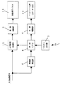
以下、本発明の液晶表示装置の第1実施形態について、図1乃至図3とともに詳細に説明する。ここで、図1は本実施形態の液晶表示装置における概略構成を示す機能ブロック図、図2は本実施形態の液晶表示装置における概略構成を示す(a)正面断面図、(b)側面断面図、図3は本実施形態の液晶表示装置におけるインパルス型表示時の動作原理を示す説明図である。
【0017】
本実施形態の液晶表示装置は、図1に示すように、液晶層と該液晶層に走査信号及びデータ信号を印加するための電極とを有するアクティブマトリクス型の液晶表示パネル1と、入力映像信号に基づいて前記液晶表示パネル1のデータ電極及び走査電極を駆動するための電極駆動部2と、前記液晶表示パネル1の裏面に配置された直下型のバックライト光源3と、バックライト光源3の点灯/消灯を行う光源駆動部4とを備えている。
【0018】
また、レターボックス方式の入力映像信号における映像部の垂直サイズをライン補間等により伸張する垂直伸張処理部5と、入力映像信号から上下部分に付加された無画部の有無を検出する無画部検出部6と、図示しないリモコン(リモートコントローラ)を用いてユーザが入力した指示信号を受信するリモコン受光部7と、無画部検出部6による無画部の検出結果と、リモコン受光部7で受信した指示信号とに基づいて、垂直伸張処理部5及び光源駆動部4に対して所定の制御信号を出力する制御CPU8とを備えている。
【0019】
尚、本実施形態においては、アスペクト比4:3の表示画面を有する、ノーマリブラックモードの液晶表示パネル1を用いるものとする。また、バックライト光源3としては、直下型蛍光灯ランプの他、直下型又はサイド照射型のLED光源、EL光源などを用いることができる。ここでは、図2に示すように、水平方向(走査線と平行方向)に分割してなるそれぞれの発光領域に対応した8本の直下型蛍光灯ランプ(CCFT)により、バックライト光源3を構成している。
【0020】
また、本実施形態の液晶表示装置は、バックライト光源3の出射光を液晶表示パネル1側に反射する反射板9と、バックライト光源3の出射光及び反射板9による反射光を拡散した上で、液晶表示パネル1に照射する拡散板10とを設けている。ここで、反射板9には各蛍光灯ランプ間を仕切るための仕切部材9aが設けられており、この仕切部材9aによって、各々の発光領域が独立して液晶表示パネル1の各表示領域を照射することが可能となっている。
【0021】
尚、図2に示した例では、断面が二等辺三角形の形状を有する仕切部材9aを、各蛍光灯ランプの長手方向(走査線と平行方向)に沿って、この二等辺三角形断面を保ったまま延伸して設けているが、その形状や大きさはこれに限られるものではない。また、仕切部材9aは反射板9と独立した部材であっても良いし、同一材料で一体的に形成しても良い。
【0022】
上記のように構成してなる液晶表示装置の動作について説明する。ユーザはリモコンを用いて、アスペクト比4:3のレターボックス方式の入力映像信号を液晶表示パネル1に表示する際、そのまま表示画面の上下部分に映像の無い無画部を表示(黒表示)する第1の表示モード(図6(a)参照)、或いは、入力映像信号に含まれるアスペクト比16:9の映像部の垂直サイズを変更することで、画面全体に画像表示を行う第2の表示モードのいずれかを切換指示することができる。
【0023】
第1の表示モードが指示されている場合、レターボックス方式の映像信号が入力されると、液晶表示パネル1の画面上下部分が無画部表示領域となり、ここに無画部が表示(黒表示)される。この無画部表示領域には表示光(バックライト光)は不要であるので、無画検出部6の検出結果に基づいて、この無画部表示領域に対応する前記バックライト光源3の発光領域を消灯するように、制御CPU8が光源駆動部4を制御する。
【0024】
ここでは、8本の蛍光灯ランプのうち、上下端部に位置する2本の蛍光灯ランプが無画部表示領域に対応する発光領域であるので、無画部が検出されている限り、これら2本の蛍光灯ランプのみを消灯する。ここで、例えばアスペクト比16:9の映画の放映番組途中に挿入されたアスペクト比4:3のCM画像入力時には、無画部は不検出となるので、制御CPU8は光源駆動部4を制御して、上下端部の2本の蛍光灯ランプも他の6本の蛍光灯ランプと同様に点灯させる。
【0025】
また、第2の表示モードが指示されている場合、レターボックス方式の映像信号が入力されると、制御CPU8は垂直伸張処理部5を制御して、アスペクト比16:9の映像部の垂直サイズを拡大するため、液晶表示パネル1にはアスペクト比4:3の画面全体に垂直サイズが伸張された映像部が表示されることとなる。従って、液晶表示パネル1の表示画面全体を照射すべく、8本の蛍光灯ランプ全てを点灯させるように、制御CPU8は光源駆動部4を制御する。
【0026】
以上のように、本実施形態の液晶表示装置は、入力映像信号における無画部の有無を検出し、この検出結果に基づいて、映像部表示領域のみを照射して、無画部表示領域に対する照射は停止すべく、バックライト光源3の各発光領域における点灯/消灯を自動制御しているので、ユーザによる特別な操作がなくとも、無駄な消費電力を低減して省エネルギーを実現することが可能となる。
【0027】
また、本実施形態においては、バックライト光源3の各発光領域間を仕切るための仕切部材9aを設けているので、映像部表示領域に対して効率的にバックライト光を照射することが可能である。さらに、走査線と平行方向に複数の発光領域を設けているので、これらを1垂直期間内で順次スキャン点灯駆動することにより、擬似的にホールド型駆動表示からCRTのようなインパルス型駆動表示に近づけて、動画表示の際に発生する動きぼけ妨害を防止することも可能となる。この走査型バックライト駆動方法について、図3とともに説明する。
【0028】
ある水平ライン群(表示分割領域)の走査(画像の書き込み)が完了してから、液晶の応答遅延分を考慮して、該水平ライン群に対応するバックライト光源3の発光領域(蛍光灯ランプ)を点灯させる。これを上下方向に次の領域、・・・と繰り返す。これによって、図3中の破線部分で示すように、バックライト点灯期間を、映像信号の書込走査箇所に対応して、時間の経過に伴い発光領域単位で、順次移行させることができる。
【0029】
ここで、第2の表示モード時には、画面全体に映像部が表示されるため、図3(a)に示すように、8本の蛍光灯ランプを各発光領域としてこれらを1フレーム(例えば60Hzのプログレッシブスキャンの場合は16.7msec)内で順次スキャン点灯するよう制御している。これによって、動きぼけ妨害を防止するとともに、各蛍光灯ランプの点灯期間短縮による消費電力の低減が可能である。
【0030】
また、第1の表示モード時には、画面上下部分が無画部表示領域となるため、図3(b)に示すように、無画部表示領域に対応する上下両端の2本の蛍光灯ランプを消灯し、アスペクト比16:9の映像部表示領域に対応する6本の蛍光灯ランプのみを順次スキャン点灯する。これによって、動きぼけ妨害の防止ばかりでなく、無画部表示領域に対応する蛍光灯ランプの非点灯による、さらなる消費電力の低減が可能となる。
【0031】
尚、上述した実施形態においては、アスペクト比4:3のレターボックス映像を表示する際の無画部表示領域に対応するバックライト光源の発光領域を自動消灯するものについて説明したが、本発明はこれに限られず、表示画面のアスペクト比と異なる種々のアスペクト比を有する画像コンテンツを表示する際に、液晶表示パネルに形成される無画部表示領域に対応するバックライト光源の発光領域を自動消灯すれば良いことは言うまでもない。
【0032】
このような種々のアスペクト比を有する画像コンテンツを表示するものにおいては、バックライト光源として直下型のLED光源を採用することによって、発光分割領域を細分化して設定することが可能となるので、より効率的に消費電力の低減を実現することができる。
【0033】
次に、本発明の液晶表示装置の第2実施形態について、図4及び図5とともに詳細に説明するが、上記第1実施形態と同一部分には同一符号を付し、その説明は省略する。ここで、図4は本実施形態の液晶表示装置における概略構成を示す機能ブロック図、図5は本実施形態の液晶表示装置における概略構成を示す(a)平面断面図、(b)正面断面図である。
【0034】
本実施形態の液晶表示装置は、図4に示すように、アスペクト比16:9の表示画面を有する、ノーマリブラックモードの液晶表示パネル11を備えるとともに、走査線と垂直方向に分割された複数の発光領域からなるバックライト光源13を備えている。また、アスペクト比16:9のサイドパネル方式の映像信号入力時に、ユーザ指示に応じて、アスペクト比4:3の映像部の水平サイズを画素補間等により伸張する水平伸張処理部15を設けている。
【0035】
尚、本実施形態では、図5に示すように、長手方向が垂直方向に延伸するように配置された8本の直下型蛍光灯ランプ(CCFT)によりバックライト光源13を構成しているが、複数個の直下型又はサイド照射型のLED光源、EL光源などを用いて構成しても良いことは、上記第1実施形態と同様である。また、バックライト光源13の出射光を液晶表示パネル11側に反射する反射板9には、各蛍光灯ランプ間を仕切るための仕切部材9aが設けられている点も、上記第1実施形態と同様である。
【0036】
上記のように構成してなる液晶表示装置の動作について説明する。ユーザはリモコンを用いて、アスペクト比16:9のサイドパネル方式の入力映像信号を液晶表示パネル11に表示する際、そのまま表示画面の左右部分に映像の無い無画部を表示(黒表示)する第1の表示モード(図6(b)参照)、或いは、入力映像信号に含まれるアスペクト比4:3の映像部の水平サイズを変更することで、画面全体に画像表示を行う第2の表示モードのいずれかを切換指示することができる。
【0037】
第1の表示モードが指示されている場合、サイドパネル方式の映像信号が入力されると、液晶表示パネル1の画面左右部分が無画部表示領域となり、ここに無画部が表示(黒表示)される。この無画部表示領域には表示光(バックライト光)は不要であるので、無画検出部6の検出結果に基づいて、この無画部表示領域に対応する前記バックライト光源13の発光領域を消灯するように、制御CPU8が光源駆動部4を制御する。
【0038】
ここでは、8本の蛍光灯ランプのうち、左右端部に位置する2本の蛍光灯ランプが無画部表示領域に対応する発光領域であるので、無画部が検出されている限り、これら2本の蛍光灯ランプのみを消灯する。例えばアスペクト比16:9の映画の放映番組途中に挿入されたアスペクト比4:3のCM画像入力時には、無画部が検出されるので、制御CPU8は光源駆動部4を制御して、左右端部の2本の蛍光灯ランプのみを消灯させる。
【0039】
また、第2の表示モードが指示されている場合、サイドパネル方式の映像信号が入力されると、制御CPU8は水平伸張処理部15を制御して、アスペクト比4:3の映像部の水平サイズを拡大するため、液晶表示パネル11にはアスペクト比16:9の画面全体に水平サイズが伸張された映像部が表示されることとなる。従って、液晶表示パネル11の表示画面全体を照射すべく、8本の蛍光灯ランプ全てを点灯させるように、制御CPU8は光源駆動部4を制御する。
【0040】
以上のように、本実施形態の液晶表示装置においては、入力映像信号における無画部の有無を検出し、この検出結果に基づいて、映像部表示領域のみを照射して、無画部表示領域に対する照射は停止すべく、バックライト光源13の各発光領域における点灯/消灯を自動制御しているので、ユーザによる特別な操作がなくとも、無駄な消費電力を低減して省エネルギーを実現することが可能となる。
【0041】
尚、上述した実施形態においては、アスペクト比16:9のサイドパネル映像を表示する際の無画部表示領域に対応するバックライト光源の発光領域を自動消灯するものについて説明したが、本発明はこれに限られず、表示画面のアスペクト比と異なる種々のアスペクト比を有する画像コンテンツを表示する際に、液晶表示パネルに形成される無画部表示領域に対応するバックライト光源の発光領域を自動消灯すれば良いことは言うまでもない。
【0042】
このような種々のアスペクト比を有する画像コンテンツを表示するものにおいては、バックライト光源として直下型のLED光源を採用することによって、発光分割領域を細分化して設定することが可能となるので、より効率的に消費電力の低減を実現することができる。
【0043】
【発明の効果】
本発明の液晶表示装置は、上記のような構成としているので、液晶表示パネルのアスペクト比と異なるアスペクト比を有する画像を表示する際の無画部表示領域に対応するバックライト光源の発光領域を自動的に消灯するので、無駄な消費電力を低減して省エネルギーを実現することが可能となる。
【図面の簡単な説明】
【図1】本発明の液晶表示装置の第1実施形態における概略構成を示す機能ブロック図である。
【図2】本発明の液晶表示装置の第1実施形態における概略構成を示す(a)正面断面図、(b)側面断面図である。
【図3】本発明の液晶表示装置の第1実施形態におけるインパルス型表示時の動作原理を示す説明図である。
【図4】本発明の液晶表示装置の第2実施形態における概略構成を示す機能ブロック図である。
【図5】本発明の液晶表示装置の第2実施形態における概略構成を示す(a)平面断面図、(b)正面断面図である。
【図6】(a)アスペクト比16:9の映像部を含むアスペクト比4:3のレターボックス映像、(b)アスペクト比4:3の映像部を含むアスペクト比16:9のサイドパネル映像をそれぞれ示す説明図である。
【符号の説明】
1、11 液晶表示パネル
2 電極駆動部
3、13 バックライト光源
4 光源駆動部
5 垂直伸張処理部
6 無画部検出部
7 リモコン受光部
8 制御CPU
15 水平伸張処理部[0001]
BACKGROUND OF THE INVENTION
The present invention relates to a liquid crystal display device that displays an image by irradiating a liquid crystal display panel using a backlight light source having a plurality of light emitting regions.
[0002]
[Prior art]
In recent years, display devices have also been required to be lighter and thinner due to lighter and thinner personal computers and television receivers. In accordance with such demands, liquid crystal display devices (LCDs) instead of cathode ray tubes (CRTs) have been demanded. ) Flat panel displays have been developed.
[0003]
The LCD applies an electric field to a liquid crystal layer having an anisotropic dielectric constant injected between two substrates, and adjusts the amount of light transmitted through the substrate by adjusting the strength of the electric field. A display device that obtains an image signal. Such LCDs are representative of portable and simple flat panel displays. Among these, TFT LCDs using thin film transistors (TFTs) as switching elements are mainly used.
[0004]
In such a liquid crystal display device, since the liquid crystal display panel itself does not emit light, it is usually necessary to dispose a backlight light source on the back surface of the liquid crystal display panel and irradiate the liquid crystal display panel. In order to reduce the power consumption due to the lighting of the backlight light source, for example, in Japanese Patent Laid-Open Nos. Hei 2-258087 and Hei 6-178240, when a synchronizing signal of an input video signal is not detected, or television reception is performed. It has been proposed to automatically turn off the backlight light source during the wave tuning operation.
[0005]
On the other hand, NTSC (National Television System Committee) color television broadcasts implemented in Japan have a video signal aspect ratio of 4: 3 and HDTV (High Definition). In the Television system, the aspect ratio of the video signal is standardized to a more horizontally long width, for example, 16: 9. Furthermore, in a movie or the like, a screen that is horizontally longer than an aspect ratio of 4: 3, which is referred to as a Vista size, is used.
[0006]
Therefore, the current letterbox is used so that the image content having a horizontally longer aspect ratio (for example, an aspect ratio of 16: 9) than the aspect ratio of 4: 3 can be received by a current NTSC television receiver (an aspect ratio of 4: 3). A display form called a method is used. In this letterbox system, as shown in FIG. 6 (a), a horizontally long screen (aspect ratio 16: 9), which is a video portion, is displayed at the center of a 4: 3 aspect ratio screen, and the upper and lower portions of the screen are displayed as images. This is a display form with no image, so that even in the current NTSC television receiver (aspect ratio 4: 3), it is possible to view movie software etc. without trimming left and right without trimming. (For example, JP-A-8-9284, JP-A-10-93985).
[0007]
Note that when this letterbox video signal is received by a wide television receiver with a horizontally long screen (aspect ratio of 16: 9), the upper and lower no-picture portions are not displayed on the screen, and only the video portion is displayed on the entire screen. Thus, a horizontally long screen (aspect ratio 16: 9) can be used effectively.
[0008]
In addition, in order to be able to receive image content having an aspect ratio of 4: 3 even with an HDTV television receiver (wide television receiver) having a horizontally long display screen (for example, an aspect ratio of 16: 9), FIG. As shown in FIG. 6 (b), a main screen having an aspect ratio of 4: 3, which is a video portion, is displayed at the center portion of the screen having an aspect ratio of 16: 9, and left and right portions thereof are displayed as non-image portions (side panel portions). ), A display form called a side panel system is known (for example, Japanese Patent Laid-Open Nos. 11-275487 and 2002-77768).
[0009]
[Patent Document 1]
Japanese Patent Laid-Open No. 2-280588 [Patent Document 2]
JP-A-6-178240 [0010]
[Problems to be solved by the invention]
In a conventional liquid crystal display device, for example, when the letterbox type or side panel type input video signal is displayed on the liquid crystal display panel as it is, depending on the aspect ratio of the video portion and the aspect ratio of the display screen, It is necessary to display a non-image area on the left and right sides (black display), but the backlight light source is always lit even in this non-image area display area, and there is a problem that wasteful power is consumed. It was.
[0011]
The present invention has been made in view of the above problems, and when displaying an image having an aspect ratio different from the aspect ratio of the screen of the liquid crystal display panel, the backlight light source is turned on for the non-image area display area. The present invention provides a liquid crystal display device capable of reducing wasteful power consumption by automatically stopping.
[0012]
[Means for Solving the Problems]
1st invention of this application is a liquid crystal display device which displays an image by irradiating a liquid crystal display panel using the backlight light source which has a some light emission area | region, Comprising: The non-image part contained in an input video signal A non-image portion detecting means for detecting the image, a first display mode for displaying the input video signal as it is, and a second display for displaying the screen by enlarging the vertical size or horizontal size of the video portion included in the input video signal. When the display mode switching means for switching the mode according to a user instruction and the first display mode are selected, the upper and lower or left and right portions of the display screen are displayed based on the detection result of the no-image portion detecting means. a light emitting region by turning off control of the backlight source corresponding to the image portion display area, when the second display mode is selected, the detection result of the non-picture portion detecting means Regardless, characterized in that a control means for lighting control of all the light-emitting region of the backlight source.
[0013]
According to a second aspect of the present invention, there is provided a partition member for partitioning the light emitting regions of the backlight light source.
[0015]
As described above, the liquid crystal display device of the present invention automatically turns off the light emission area of the backlight light source corresponding to the non-image area display area that does not require display light on the liquid crystal display panel, thus reducing wasteful power consumption and saving energy. Can be realized.
[0016]
DETAILED DESCRIPTION OF THE INVENTION
Hereinafter, a liquid crystal display device according to a first embodiment of the present invention will be described in detail with reference to FIGS. Here, FIG. 1 is a functional block diagram showing a schematic configuration of the liquid crystal display device of the present embodiment, FIG. 2 is a schematic cross-sectional view of the liquid crystal display device of the present embodiment, (a) front sectional view, (b) side sectional view. FIG. 3 is an explanatory diagram showing an operation principle at the time of impulse-type display in the liquid crystal display device of the present embodiment.
[0017]
As shown in FIG. 1, the liquid crystal display device of this embodiment includes an active matrix type liquid
[0018]
Also, a vertical
[0019]
In this embodiment, a normally black mode liquid
[0020]
In addition, the liquid crystal display device of the present embodiment has a
[0021]
In the example shown in FIG. 2, the isosceles triangular section is maintained along the longitudinal direction (parallel to the scanning line) of each fluorescent lamp lamp in the partition member 9a having a cross section of an isosceles triangle. Although it is stretched as it is, its shape and size are not limited to this. Moreover, the partition member 9a may be a member independent of the reflecting
[0022]
The operation of the liquid crystal display device configured as described above will be described. When a user displays a letterbox-type input video signal having an aspect ratio of 4: 3 on the liquid
[0023]
When the first display mode is instructed, when a letterbox video signal is input, the upper and lower portions of the liquid
[0024]
Here, of the eight fluorescent lamps, two fluorescent lamps positioned at the upper and lower ends are light emitting areas corresponding to the non-image area display area. Turn off only the two fluorescent lamps. Here, for example, when inputting a CM image with an aspect ratio of 4: 3 inserted in the air of a 16: 9 movie, the control CPU 8 controls the light source drive unit 4 because no image portion is not detected. Thus, the two fluorescent lamps at the upper and lower ends are lit in the same manner as the other six fluorescent lamps.
[0025]
Further, when the second display mode is instructed, when a letterbox video signal is input, the control CPU 8 controls the vertical
[0026]
As described above, the liquid crystal display device of the present embodiment detects the presence or absence of a non-image area in the input video signal, and irradiates only the video area display area based on the detection result, Since turning on / off each light emitting area of the
[0027]
Further, in the present embodiment, since the partition member 9a for partitioning the light emitting areas of the
[0028]
After the scanning (image writing) of a certain horizontal line group (display divided area) is completed, the light emitting area (fluorescent lamp) corresponding to the horizontal line group is considered in consideration of the response delay of the liquid crystal. ) Is lit. This is repeated with the next region in the vertical direction. As a result, as shown by the broken line portion in FIG. 3, the backlight lighting period can be sequentially shifted in units of light emitting areas with the passage of time corresponding to the writing scanning position of the video signal.
[0029]
Here, in the second display mode, since the video portion is displayed on the entire screen, as shown in FIG. 3A, eight fluorescent lamps are used as the respective light emitting areas, and these are set in one frame (for example, 60 Hz). In the case of progressive scan, it is controlled so that the scan lights up sequentially within 16.7 msec). As a result, it is possible to prevent motion blur and reduce power consumption by shortening the lighting period of each fluorescent lamp.
[0030]
In the first display mode, the upper and lower parts of the screen are the non-image area display area. Therefore, as shown in FIG. 3B, two fluorescent lamps at the upper and lower ends corresponding to the non-image area display area are displayed. The light is turned off, and only the six fluorescent lamps corresponding to the video portion display area having an aspect ratio of 16: 9 are sequentially turned on. As a result, it is possible not only to prevent motion blur but also to further reduce power consumption by not lighting the fluorescent lamp corresponding to the non-image area display area.
[0031]
In the above-described embodiment, the description has been given of the case where the light emission area of the backlight light source corresponding to the non-image area display area when displaying the letterbox image having the aspect ratio of 4: 3 is automatically turned off. Not limited to this, when displaying image content with various aspect ratios different from the aspect ratio of the display screen, the light emission area of the backlight light source corresponding to the non-image area display area formed on the liquid crystal display panel is automatically turned off. It goes without saying that it should be done.
[0032]
In the case of displaying image content having such various aspect ratios, by adopting a direct type LED light source as a backlight light source, it becomes possible to subdivide and set the light emission divided region. Reduction of power consumption can be realized efficiently.
[0033]
Next, a liquid crystal display device according to a second embodiment of the present invention will be described in detail with reference to FIGS. 4 and 5. The same reference numerals are given to the same portions as those in the first embodiment, and description thereof will be omitted. Here, FIG. 4 is a functional block diagram showing a schematic configuration of the liquid crystal display device of the present embodiment, FIG. 5 is (a) a plan sectional view showing a schematic configuration of the liquid crystal display device of the present embodiment, and (b) a front sectional view. It is.
[0034]
As shown in FIG. 4, the liquid crystal display device of the present embodiment includes a normally black mode liquid
[0035]
In the present embodiment, as shown in FIG. 5, the
[0036]
The operation of the liquid crystal display device configured as described above will be described. When the user displays a side panel type input video signal having an aspect ratio of 16: 9 on the liquid
[0037]
When the first display mode is instructed, when a side panel video signal is input, the left and right parts of the screen of the liquid
[0038]
Here, of the eight fluorescent lamps, two fluorescent lamps located at the left and right ends are light emitting areas corresponding to the non-image area display area. Turn off only the two fluorescent lamps. For example, when inputting a CM image with an aspect ratio of 4: 3 inserted in a broadcast program of a movie with an aspect ratio of 16: 9, a non-image area is detected. Only the two fluorescent lamps are turned off.
[0039]
In addition, when the second display mode is instructed, when a side panel video signal is input, the control CPU 8 controls the horizontal
[0040]
As described above, in the liquid crystal display device of the present embodiment, the presence or absence of a non-image portion in the input video signal is detected, and based on the detection result, only the video portion display region is irradiated, and the non-image portion display region Since the lighting / extinction in each light emitting area of the
[0041]
In the above-described embodiment, the description has been given of the case where the light emission area of the backlight light source corresponding to the non-image area display area when the side panel image having the aspect ratio of 16: 9 is displayed is automatically turned off. Not limited to this, when displaying image content with various aspect ratios different from the aspect ratio of the display screen, the light emission area of the backlight light source corresponding to the non-image area display area formed on the liquid crystal display panel is automatically turned off. It goes without saying that it should be done.
[0042]
In the case of displaying image content having such various aspect ratios, by adopting a direct type LED light source as a backlight light source, it becomes possible to subdivide and set the light emission divided region. Reduction of power consumption can be realized efficiently.
[0043]
【The invention's effect】
Since the liquid crystal display device of the present invention is configured as described above, the light emission area of the backlight source corresponding to the non-image area display area when displaying an image having an aspect ratio different from the aspect ratio of the liquid crystal display panel is provided. Since it automatically turns off, it is possible to reduce energy consumption by reducing wasteful power consumption.
[Brief description of the drawings]
FIG. 1 is a functional block diagram showing a schematic configuration in a first embodiment of a liquid crystal display device of the present invention.
2A is a front sectional view showing a schematic configuration of the liquid crystal display device according to the first embodiment of the present invention, and FIG.
FIG. 3 is an explanatory diagram illustrating an operation principle during impulse-type display in the first embodiment of the liquid crystal display device of the present invention.
FIG. 4 is a functional block diagram showing a schematic configuration in a second embodiment of the liquid crystal display device of the present invention.
FIGS. 5A and 5B are a schematic cross-sectional view and a front cross-sectional view, respectively, showing a schematic configuration of a liquid crystal display device according to a second embodiment of the present invention.
6A is a letterbox image having an aspect ratio of 4: 3 including an image portion having an aspect ratio of 16: 9, and FIG. 6B is a side panel image having an aspect ratio of 16: 9 including an image portion having an aspect ratio of 4: 3. It is explanatory drawing shown, respectively.
[Explanation of symbols]
DESCRIPTION OF
15 Horizontal stretch processing unit
Claims (2)
入力映像信号に含まれる無画部を検出する無画部検出手段と、
入力映像信号をそのまま画面表示する第1の表示モードと、入力映像信号に含まれる映像部の垂直サイズ或いは水平サイズを拡大して画面表示する第2の表示モードとを、ユーザの指示により切り換える表示モード切換手段と、
前記第1の表示モードが選択されている場合、前記無画部検出手段の検出結果に基づいて、表示画面における上下または左右部分の無画部表示領域に対応する前記バックライト光源の発光領域を消灯制御するとともに、前記第2の表示モードが選択されている場合、前記無画部検出手段の検出結果に関わらず、前記バックライト光源の全ての発光領域を点灯制御する制御手段とを備えたことを特徴とする液晶表示装置。A liquid crystal display device that displays an image by irradiating a liquid crystal display panel using a backlight light source having a plurality of light emitting regions,
A non-image portion detecting means for detecting a non-image portion included in the input video signal;
A display that switches between a first display mode in which an input video signal is displayed on the screen as it is and a second display mode in which the vertical or horizontal size of the video portion included in the input video signal is enlarged and displayed on the screen according to a user instruction. Mode switching means;
When the first display mode is selected, based on the detection result of the no-image portion detection unit, the light emission region of the backlight light source corresponding to the no-image portion display regions of the upper and lower or left and right portions on the display screen by turning off control, when the second display mode is selected, regardless of the detection result of the non-picture portion detecting means, and control means for lighting control of all the light-emitting region of the backlight source A liquid crystal display device characterized by the above.
前記バックライト光源の各発光領域間を仕切るための仕切部材を設けたことを特徴とする液晶表示装置。The liquid crystal display device according to claim 1,
A liquid crystal display device comprising a partition member for partitioning light emitting regions of the backlight light source.
Priority Applications (1)
| Application Number | Priority Date | Filing Date | Title |
|---|---|---|---|
| JP2002355035A JP4177652B2 (en) | 2002-12-06 | 2002-12-06 | Liquid crystal display |
Applications Claiming Priority (1)
| Application Number | Priority Date | Filing Date | Title |
|---|---|---|---|
| JP2002355035A JP4177652B2 (en) | 2002-12-06 | 2002-12-06 | Liquid crystal display |
Publications (3)
| Publication Number | Publication Date |
|---|---|
| JP2004184937A JP2004184937A (en) | 2004-07-02 |
| JP2004184937A5 JP2004184937A5 (en) | 2005-08-25 |
| JP4177652B2 true JP4177652B2 (en) | 2008-11-05 |
Family
ID=32755844
Family Applications (1)
| Application Number | Title | Priority Date | Filing Date |
|---|---|---|---|
| JP2002355035A Expired - Fee Related JP4177652B2 (en) | 2002-12-06 | 2002-12-06 | Liquid crystal display |
Country Status (1)
| Country | Link |
|---|---|
| JP (1) | JP4177652B2 (en) |
Families Citing this family (21)
| Publication number | Priority date | Publication date | Assignee | Title |
|---|---|---|---|---|
| JP2006337498A (en) * | 2005-05-31 | 2006-12-14 | Sharp Corp | Display device |
| JP2007163562A (en) * | 2005-12-09 | 2007-06-28 | Sharp Corp | Video display device and video display method |
| JP4808073B2 (en) * | 2006-05-22 | 2011-11-02 | シャープ株式会社 | Display device |
| JP2007334176A (en) * | 2006-06-19 | 2007-12-27 | Sharp Corp | Video display apparatus and television receiver |
| JP4489734B2 (en) * | 2006-07-07 | 2010-06-23 | 株式会社 日立ディスプレイズ | Liquid crystal display |
| JP2008116554A (en) * | 2006-11-01 | 2008-05-22 | Sharp Corp | Backlight control device and video display device equipped with the backlight control device |
| JP2008306421A (en) * | 2007-06-07 | 2008-12-18 | Sharp Corp | Digital broadcasting receiver, and digital broadcasting receiving method |
| JP5642347B2 (en) * | 2008-03-07 | 2014-12-17 | ミツミ電機株式会社 | LCD backlight device |
| WO2009130820A1 (en) | 2008-04-21 | 2009-10-29 | シャープ株式会社 | Image processing device, display, image processing method, program, and recording medium |
| JP2009294436A (en) * | 2008-06-05 | 2009-12-17 | Sharp Corp | Backlight device and liquid crystal display device |
| BRPI0912858A2 (en) | 2008-06-27 | 2019-03-06 | Sharp Kk | liquid crystal display control device, liquid crystal display device, liquid crystal display device control method, program and storage medium for program |
| CN102016699B (en) | 2008-06-27 | 2012-11-21 | 夏普株式会社 | Control device for liquid crystal display device, control method for liquid crystal display device, program, and recording medium |
| EP2353158B1 (en) | 2008-09-30 | 2016-01-13 | Dolby Laboratories Licensing Corporation | Improved power management for modulated backlights |
| JP5176896B2 (en) * | 2008-11-19 | 2013-04-03 | 株式会社Jvcケンウッド | Liquid crystal display |
| WO2011013404A1 (en) | 2009-07-29 | 2011-02-03 | シャープ株式会社 | Image display device and image display method |
| CN102792362B (en) | 2010-03-26 | 2015-09-30 | 夏普株式会社 | Image display device and control method thereof |
| KR101689819B1 (en) * | 2010-11-01 | 2016-12-26 | 삼성전자주식회사 | Dispaly apparatus and method for improving image quality therof |
| JP2011076106A (en) * | 2010-11-17 | 2011-04-14 | Sharp Corp | Liquid crystal display device |
| US8885103B2 (en) | 2010-12-28 | 2014-11-11 | Sharp Kabushiki Kaisha | Display device and television receiver |
| JP6045138B2 (en) * | 2011-11-29 | 2016-12-14 | キヤノン株式会社 | Image display apparatus and control method thereof |
| JP6200658B2 (en) * | 2013-02-27 | 2017-09-20 | 株式会社メガチップス | Display control device |
-
2002
- 2002-12-06 JP JP2002355035A patent/JP4177652B2/en not_active Expired - Fee Related
Also Published As
| Publication number | Publication date |
|---|---|
| JP2004184937A (en) | 2004-07-02 |
Similar Documents
| Publication | Publication Date | Title |
|---|---|---|
| JP4177652B2 (en) | Liquid crystal display | |
| KR100662161B1 (en) | Liquid crystal display and driving method used for same | |
| KR100857990B1 (en) | Backlight Unit Structure of LCD | |
| WO2007072598A1 (en) | Display device, receiver, and method of driving display device | |
| JP4139189B2 (en) | Liquid crystal display | |
| US7692621B2 (en) | Liquid crystal display device and a method for driving the same | |
| JP3110340B2 (en) | Backlight control method and liquid crystal display device | |
| JP2001142409A (en) | Video display device and illumination control method in the video display device | |
| US7907238B2 (en) | Backlight unit and display device using the same | |
| JP2003050569A (en) | Liquid crystal display | |
| JP4167474B2 (en) | Liquid crystal display | |
| WO2006123706A1 (en) | Liquid crystal display device and drive method thereof | |
| US7999886B2 (en) | Backlight apparatus and liquid crystal apparatus having particular light emission control | |
| JP4808073B2 (en) | Display device | |
| JP2009283383A (en) | Surface lighting device and image display device | |
| JPH10254390A (en) | Liquid crystal device | |
| JP3566224B2 (en) | Image display device, luminous body, driving method of luminous body | |
| JP2007179010A (en) | Liquid crystal display device and driving method of the same | |
| RU2447469C2 (en) | Liquid crystal display | |
| WO2007072599A1 (en) | Display device drive method, display device, and reception device using the same | |
| JP2001194664A (en) | Liquid crystal display | |
| JP2009110730A (en) | Illumination device and liquid crystal display device | |
| KR101152581B1 (en) | Method for driving liquid crystal display | |
| JP4149257B2 (en) | Liquid crystal display | |
| JP2007264295A (en) | LCD flat panel display |
Legal Events
| Date | Code | Title | Description |
|---|---|---|---|
| A521 | Written amendment |
Free format text: JAPANESE INTERMEDIATE CODE: A523 Effective date: 20050221 |
|
| A621 | Written request for application examination |
Free format text: JAPANESE INTERMEDIATE CODE: A621 Effective date: 20050525 |
|
| A977 | Report on retrieval |
Free format text: JAPANESE INTERMEDIATE CODE: A971007 Effective date: 20070410 |
|
| RD01 | Notification of change of attorney |
Free format text: JAPANESE INTERMEDIATE CODE: A7421 Effective date: 20071205 |
|
| A131 | Notification of reasons for refusal |
Free format text: JAPANESE INTERMEDIATE CODE: A131 Effective date: 20080212 |
|
| A521 | Written amendment |
Free format text: JAPANESE INTERMEDIATE CODE: A523 Effective date: 20080319 |
|
| TRDD | Decision of grant or rejection written | ||
| A01 | Written decision to grant a patent or to grant a registration (utility model) |
Free format text: JAPANESE INTERMEDIATE CODE: A01 Effective date: 20080805 |
|
| A01 | Written decision to grant a patent or to grant a registration (utility model) |
Free format text: JAPANESE INTERMEDIATE CODE: A01 |
|
| A61 | First payment of annual fees (during grant procedure) |
Free format text: JAPANESE INTERMEDIATE CODE: A61 Effective date: 20080822 |
|
| FPAY | Renewal fee payment (event date is renewal date of database) |
Free format text: PAYMENT UNTIL: 20110829 Year of fee payment: 3 |
|
| R150 | Certificate of patent or registration of utility model |
Free format text: JAPANESE INTERMEDIATE CODE: R150 |
|
| FPAY | Renewal fee payment (event date is renewal date of database) |
Free format text: PAYMENT UNTIL: 20110829 Year of fee payment: 3 |
|
| FPAY | Renewal fee payment (event date is renewal date of database) |
Free format text: PAYMENT UNTIL: 20120829 Year of fee payment: 4 |
|
| FPAY | Renewal fee payment (event date is renewal date of database) |
Free format text: PAYMENT UNTIL: 20120829 Year of fee payment: 4 |
|
| FPAY | Renewal fee payment (event date is renewal date of database) |
Free format text: PAYMENT UNTIL: 20130829 Year of fee payment: 5 |
|
| LAPS | Cancellation because of no payment of annual fees |