JP4171274B2 - battery pack - Google Patents
battery pack Download PDFInfo
- Publication number
- JP4171274B2 JP4171274B2 JP2002285639A JP2002285639A JP4171274B2 JP 4171274 B2 JP4171274 B2 JP 4171274B2 JP 2002285639 A JP2002285639 A JP 2002285639A JP 2002285639 A JP2002285639 A JP 2002285639A JP 4171274 B2 JP4171274 B2 JP 4171274B2
- Authority
- JP
- Japan
- Prior art keywords
- battery
- current
- voltage
- overcharge state
- state
- Prior art date
- Legal status (The legal status is an assumption and is not a legal conclusion. Google has not performed a legal analysis and makes no representation as to the accuracy of the status listed.)
- Expired - Fee Related
Links
Images


Classifications
-
- Y—GENERAL TAGGING OF NEW TECHNOLOGICAL DEVELOPMENTS; GENERAL TAGGING OF CROSS-SECTIONAL TECHNOLOGIES SPANNING OVER SEVERAL SECTIONS OF THE IPC; TECHNICAL SUBJECTS COVERED BY FORMER USPC CROSS-REFERENCE ART COLLECTIONS [XRACs] AND DIGESTS
- Y02—TECHNOLOGIES OR APPLICATIONS FOR MITIGATION OR ADAPTATION AGAINST CLIMATE CHANGE
- Y02E—REDUCTION OF GREENHOUSE GAS [GHG] EMISSIONS, RELATED TO ENERGY GENERATION, TRANSMISSION OR DISTRIBUTION
- Y02E60/00—Enabling technologies; Technologies with a potential or indirect contribution to GHG emissions mitigation
- Y02E60/10—Energy storage using batteries
Landscapes
- Protection Of Static Devices (AREA)
- Secondary Cells (AREA)
Description
【0001】
【発明の属する技術分野】
本発明は、電池を過充電から有効に防止できるバッテリーパックに関する。
【0002】
【従来の技術】
電池は、過充電すると電気的な性能が著しく低下するばかりでなく、内部でガスが発生して内圧が異常に上昇し、あるいは電池温度が高くなる等の弊害がある。この弊害を防止するために、過充電を検出して充電電流を遮断する回路を内蔵するバッテリーパックが開発されている。このバッテリーパックは、電池の過充電を検出する制御回路と、この制御回路に制御されるスイッチング素子を備える。制御回路は、電池電圧を検出して、検出した電池電圧が設定電圧よりも高いと過充電と判定して、スイッチング素子をオンからオフに切り換えて充電電流を遮断する。
【0003】
【発明が解決しようとする課題】
電池の過充電を、電圧が設定電圧よりも高くなったことで検出する制御回路は、正確に電池の過充電を検出するのが難しい。たとえば、設定電圧を低くすると、過充電でない電池を間違って過充電と判定することがある。それは、電池の電圧特性や雑音、あるいはその他の原因で電池電圧が一時的に高くなることがあるからである。誤検出を避けるために、過充電と判定する設定電圧を高くすると、過充電を速やかに検出できなくなって、電池の性能を低下させる。この弊害を少なくするために、電池電圧が設定電圧よりも高くなった時間を検出して、設定電圧よりも高くなる時間が設定時間よりも長くなると過充電と判定する制御回路が開発されている。
【0004】
しかしながら、この制御回路といえども理想的な状態で過充電を検出して充電を停止できないことがある。それは、過充電になってスイッチング素子をオフに切り換えできないと、安全に使用できなくなるからである。さらに理想的な状態で充電電流を遮断するために、スイッチング素子に加えて、非復帰電流遮断素子であるヒューズを内蔵するバッテリーパックも開発されている。このバッテリーパックは、電池電圧が設定電圧よりも高くなるとスイッチング素子をオフに切り換えて充電を停止させるが、この状態でスイッチング素子をオフに切り換えできなくて、さらに電池電圧が高くなって最大設定電圧を越えるとヒューズを溶断して再使用できない状態とする。このバッテリーパックは、再使用できる程度の過充電では、スイッチング素子をオフにして一時的に充電電流を遮断するが、過充電で電流を遮断する回路が何らかの原因で故障してさらに電池電圧が高くなると、ヒューズを溶断して使用できなくする。したがって安全に使用できる。
【0005】
しかしながら、このバッテリーパックといえども、電池を理想的な状態で充電するのは難しい。とくに、過充電を正確に検出して充電を停止させるのは極めて難しい。とくに、過充電を確実に検出することと、実質的な充電容量を大きくすることが互いに相反する特性であるために、充電容量を大きくしながら過充電を確実に検出するのが極めて難しい。さらに、バッテリーパックは、電池の寿命が尽きると廃棄されることから過充電を検出する回路構成を簡単にして安価に多量生産できることも大切である。すなわち、製造コストを低減しながら、正確に過充電を検出して、しかも実質的に使用できる時間を最大にすることが要求されるが、これ等の全ての特性を満足するのは極めて難しい。本発明は、このような欠点を解決することを目的に開発されたものである。
【0006】
【課題を解決するための手段】
本発明のバッテリーパックは、電池1が最大過充電状態にあると判定する保護回路2と、電池1が過充電状態にあると検出する制御回路3と、電池1の充電電流を遮断する電流遮断部4とを備える。保護回路2は、電池電圧を検出して電池電圧が最大設定電圧よりも高くなり、かつ最大設定電圧よりも高くなる時間が最小設定時間よりも長くなると電池1が最大過充電状態にあると判定する。制御回路3は、電池電圧が最大設定電圧よりも低く設定された設定電圧よりも高くなり、かつ電池電圧が設定電圧よりも高くなる時間が設定時間よりも長くなると電池1が過充電状態にあると検出する。電流遮断部4は、制御回路3と保護回路2が電池1の過充電状態を検出すると、電池1の充電電流を遮断する。さらに、制御回路3は、電池電圧が最大設定電圧よりも低く設定された第1設定電圧よりも高くなり、かつ第1設定電圧よりも高くなる時間が第1設定時間よりも長くなったことを検出する第1過充電状態と、電池電圧が、第1設定電圧よりも低い電圧に設定している第2設定電圧よりも高くなり、かつ第2設定電圧よりも高くなる時間が第1設定時間よりも長く設定している第2設定時間よりも長くなったことを検出する第2過充電状態とを検出する。電流遮断部4は、制御回路3が第1過充電状態と第2過充電状態のいずれか一方を検出する状態と、保護回路2が最大過充電状態を検出する状態とで電池1の充電電流を遮断する。
【0007】
保護回路2は、第1設定時間よりも短い設定時間である最小設定時間を記憶して、電池電圧が最大設定電圧よりも高くなる時間が最小設定時間よりも長くなると電池1が最大過充電状態であると判定することができる。
【0008】
電流遮断部4は、電池1の充電電流を遮断するスイッチング素子7と、電池1の充電ラインに接続している非復帰電流遮断素子9とを備え、第1過充電状態でスイッチング素子7をオンからオフに切り換え、第2過充電状態で非復帰電流遮断素子9を制御して充電電流を遮断することができる。電流遮断部4は、第1過充電状態でスイッチング素子をオンからオフに切り換え、第2過充電状態でスイッチング素子7をオンからオフに切り換えると共に、非復帰電流遮断素子9を制御して充電電流を遮断することもできる。
【0009】
さらに、電流遮断部4は、電池1の充電電流を遮断するスイッチング素子7と、電池1の充電ラインに接続している非復帰電流遮断素子9とを備え、保護回路2が最大過充電状態を検出すると非復帰電流遮断素子9を制御して充電電流を遮断することができる。さらに、電流遮断部4は、保護回路2が最大過充電状態を検出すると非復帰電流遮断素子9を制御して充電電流を遮断し、制御回路3が第1過充電状態を検出するとスイッチング素子7をオンからオフに切り換え、第2過充電状態を検出すると非復帰電流遮断素子9を制御して充電電流を遮断することができる。さらにまた、電流遮断部4は、保護回路2が最大過充電状態を検出すると非復帰電流遮断素子9を制御して充電電流を遮断し、制御回路3が第1過充電状態を検出するとスイッチング素子7をオンからオフに切り換え、第2過充電状態を検出すると、スイッチング素子7をオンからオフに切り換えると共に、非復帰電流遮断素子9を制御して充電電流を遮断することができる。
【0010】
【発明の実施の形態】
以下、本発明の実施例を図面に基づいて説明する。ただし、以下に示す実施例は、本発明の技術思想を具体化するためのバッテリーパックを例示するものであって、本発明はバッテリーパックを以下のものに特定しない。
【0011】
さらに、この明細書は、特許請求の範囲を理解しやすいように、実施例に示される部材に対応する番号を、「特許請求の範囲の欄」、および「課題を解決するための手段の欄」に示される部材に付記している。ただ、特許請求の範囲に示される部材を、実施例の部材に特定するものでは決してない。
【0012】
以下、コンピュータの電源、とくにラップトツプ型のコンピュータの電源に使用されるバッテリーパックの具体例を示す。ただし、本発明のバッテリーパックは、コンピュータ以外の電源にも使用されるのは言うまでもない。
【0013】
図1のバッテリーパックは、電池電圧を検出して電池電圧が最大設定電圧よりも高くなり、かつ最大設定電圧よりも高くなる時間が最小設定時間よりも長くなると電池1が最大過充電状態にあると判定する保護回路2と、電池電圧が最大設定電圧よりも低く設定された設定電圧よりも高くなり、かつ電池電圧が設定電圧よりも高くなる時間が設定時間よりも長くなると電池1が過充電状態にあると検出する制御回路3と、この制御回路3と保護回路2のいずれかが電池1の過充電状態を検出すると、電池1の充電電流を遮断する電流遮断部4とを備える。さらに、図のバッテリーパックは、電池温度を検出する電池温度センサー5と、バッテリーパック内の温度を検出する内部温度センサー6とを備えている。電池温度センサー5は制御回路3に接続され、内部温度センサー6は通信端子を介して、バッテリーパックを装着する電気機器に接続される。制御回路3は、電池温度センサー5で電池温度を検出し、電池温度が最高温度よりも高くなると、電池1に流れる電流を遮断する。
【0014】
図2は、保護回路2と制御回路3が充電電流を遮断する条件を示すグラフである。この図は、リチウムイオン二次電池を内蔵するバッテリーパックの電圧を例示している。バッテリーパックは、リチウムイオン二次電池以外の電池、たとえばニッケル−水素電池やニッケル−カドミウム電池等の二次電池を内蔵することもできる。バッテリーパックに内蔵される二次電池の種類により出力電圧は相違する。したがって、バッテリーパックの保護回路2や制御回路3は、過充電と判定する電圧を電池の種類を考慮して最適電圧に設定する。
【0015】
保護回路2は、この図に示すように、電池電圧が最大設定電圧よりも高くなり、かつ電池電圧が最大設定電圧よりも高くなる時間が最小設定時間よりも長くなると最大過充電状態にあると判定する。図の保護回路2は、最大設定電圧を4.45V/セルに設定して、最小設定時間を1.5秒に設定している。したがって、電池電圧が4.45Vよりも高くなる時間が1.5秒以上続くと、最大過充電状態と判定する。保護回路2は、電池電圧が最大設定電圧よりも高くなったことを検出するために、コンパレータと基準電源とタイマーとを備える。基準電源の電圧は、最大設定電圧に等しい。コンパレータは、電池電圧を基準電源に比較して、電池電圧が基準電源を越えると”High”、電池電圧が基準電源よりも低いと”Low”を出力する。コンパレータが”High”を出力すると、タイマーがカウントを開始し、1.5秒経過すると最大過充電状態であることを示す信号を出力する。保護回路2は、A/Dコンバータと、演算回路と、メモリで構成することもできる。この保護回路2は、電池電圧をA/Dコンバータでデジタル値に変換する。変換されたデジタル値の電池電圧は、メモリに記憶される最大設定電圧に演算回路で比較される。電池電圧が最大設定電圧よりも高くなるとタイマーがカウントを開始して、設定時間になると最大過充電状態であることを示す信号を出力する。
【0016】
制御回路3は、第1設定電圧及び第2設定電圧を記憶しているメモリと、電池電圧をデジタル値に変換するA/Dコンバータと、このA/Dコンバータで変換されたデジタル信号の電圧値から第1過充電状態と第2過充電状態を判別するコントローラとを備えている。コントローラは、第1設定時間と第2設定時間をカウントする第1タイマーと第2タイマーとを備える。
【0017】
A/Dコンバータは、一定のサンプリング周期で、電池電圧をデジタル値に変換し、変換されたデジタル値の信号がコントローラに入力される。コントローラは、A/Dコンバータから入力される電圧信号から、第1過充電状態と第2過充電状態を判別し、電流遮断部4を制御して過充電を防止する。さらに、コントローラは、電池1に流れる充電電流と放電電流を積算して電池1の残容量を演算する。また、コントローラは、電池1の過放電を検出する。電池1が過放電になると、コントローラは電流遮断部4を制御して電池1の放電電流を遮断する。
【0018】
制御回路3は、電池電圧が最大設定電圧よりも低く設定された第1設定電圧よりも高くなり、かつ第1設定電圧よりも高くなる時間が第1設定時間よりも長くなったことを検出する第1過充電状態と、電池電圧が、第1設定電圧よりも低い電圧に設定している第2設定電圧よりも高くなり、かつ第2設定電圧よりも高くなる時間が第1設定時間よりも長く設定している第2設定時間よりも長くなったことを検出する第2過充電状態とを検出する。
【0019】
制御回路3は、たとえば図2に示すように、第1設定電圧を4.35V/セル、第1設定時間を10秒として、第2設定電圧を4.30V/セル、第2設定時間を20秒とする。第1設定電圧と第2設定電圧はメモリに記憶され、第1設定時間と第2設定時間はタイマーにカウントされる。
【0020】
図のバッテリーパックの電流遮断部4は、スイッチング素子7、8と非復帰電流遮断素子9を備える。図の電流遮断部4は、充電を制御するスイッチング素子7と、放電を制御するスイッチング素子8とを備える。充電を制御するスイッチング素子7は、電池1を充電しているときにオンからオフに切り換えられて、充電電流を遮断する。放電を制御するスイッチング素子8は、電池1を放電している状態でオンからオフに切り換えられて放電電流を遮断する。これ等のスイッチング素子7、8は、制御回路3でオンオフに制御される。
【0021】
非復帰電流遮断素子9は、電流を遮断する状態に切り換えられると、その後、通電できる状態には切り換えできない素子である。図の非復帰電流遮断素子9は、ヒューズ10とこのヒューズ10を加熱する加熱抵抗11と、この加熱抵抗11に通電してヒューズ10を遮断する溶断スイッチ12とを備えている。この非復帰電流遮断素子9は、電流を遮断するときに溶断スイッチ12をオンに切り換える。溶断スイッチ12がオンになると、加熱抵抗11に通電され、これがヒューズ10を加熱して溶断する。溶断されたヒューズ10は、その後に、電池1の過充電状態が解除されてもオン状態に復帰することはない。溶断スイッチ12は、FETやトランジスター等の半導体スイッチング素子である。溶断スイッチ12は、制御回路3に制御されて加熱抵抗11に通電し、ヒューズ10を溶断する。以上の構造の非復帰電流遮断素子9は、ヒューズ10を溶断して電流を遮断するが、本発明は非復帰電流遮断素子を以上の構造には特定しない。非復帰電流遮断素子には、電流を遮断した後、過充電状態が解除されてもオン状態に復帰しない全ての素子を使用することができる。
【0022】
電流遮断部4は、制御回路3と保護回路2に制御されて、充電している電池1の充電電流を遮断する。すなわち、制御回路3が、第1過充電状態と第2過充電状態のいずれか一方を検出する状態と、保護回路2が最大過充電状態を検出する状態とで、電池1の充電電流を遮断する。
【0023】
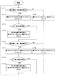
制御回路3は、図3に示す以下のフローチャートで電流遮断部4を制御して充電電流を遮断する。
[n=1のステップ]
電源スイッチがオンになってリセットされると、n=1のステップにおいて、A/Dコンバータは、一定のサンプリング周期で電池電圧を検出し、検出したアナログ値の電圧信号をデジタル信号に変換する。
さらに、図1のバッテリーパックは、電池1に流れる電流を検出し、検出されたアナログの電流信号を、一定のサンプリング周期でデジタル値に変換する。また、電池温度を検出する電池温度センサー5の出力もデジタル値に変換される。A/Dコンバータで変換されたデジタル信号は、一時的にメモリであるRAMに記憶される。
A/Dコンバータが、電圧、電流、温度をデジタル値に変換するサンプリング周期は、たとえば250msecとする。ただし、サンプリング周期は、さらに短い周期として、電池電圧の変化をより速やかに検出し、あるいはさらに長い周期として電池電圧の変化を検出することができる。したがって、サンプリング周期は、たとえば10msec〜1sec、好ましくは30msec〜500msec、好ましくは50msec〜500msecとすることができる。
[n=2のステップ]
制御回路3は、検出した電池電圧に基づいて、電池1の第1過充電状態と第2過充電状態とを判別する。
[n=3のステップ]
第1過充電状態と第2過充電状態の判別に基づいて、電流遮断部4でスイッチング素子7や非復帰電流遮断素子9を制御する。
[n=4のステップ]
制御回路3が、検出された電流信号等に基づいて電池1の残容量を演算する。
【0024】
以上のn=2〜3のステップにおいて、制御回路3のコントローラが、電池電圧から電流遮断部4を制御するフローチャートの詳細を図4に示している。このフローチャートは、以下のステップで電流遮断部4を制御する。
[n=1〜2のステップ]
コントローラは、第1過充電状態であるかどうかを判定し、第1過充電状態であるとスイッチング素子7をオンからオフに切り換えて、充電電流を遮断する。第1過充電状態にないと、次のn=3のステップにジャンプする。
[n=3〜4のステップ]
第2過充電状態であるかどうかを判定し、第2過充電状態であると、非復帰電流遮断素子9を制御している充電電流を遮断する。第2過充電状態でないと、n=1のステップにジャンプする。
【0025】
さらに、制御回路3のコントローラは、図5に示すようにして、以下のフローチャートで第1過充電状態と第2過充電状態とを判別する。
[n=1〜2のステップ]
電池電圧が第2設定電圧よりも高いかどうかを判別する。電池電圧が第2設定電圧よりも大きいと、第2タイマーのカウント値t2をインクリメントする。すなわち、第2タイマーのカウント値t2に1をプラスする。
図1に示すように、複数の二次電池1を直列に接続しているバッテリーパックは、各々の電池電圧を検出して、最も高い電池電圧を第2設定電圧に比較する。第1設定電圧に比較するときも同じように、最も高い電池電圧を第1設定電圧に比較する。ひとつの電池を内蔵するバッテリーパックは、検出した電池電圧を第2設定電圧、第1設定電圧に比較する。
[n=3のステップ]
電池電圧が第2設定電圧よりも高くないと、このステップで第2タイマーのカウント値t2を0にリセットする。
[n=4〜5のステップ]
第2タイマーのカウント値t2が第2設定時間よりも長いかどうかを判定する。第2タイマーのカウント値t2が第2設定時間よりも長いと、n=5のステップで第2過充電状態と判定して、第2タイマーのカウント値t2を0にリセットする。第2過充電状態であると判定されると、図4のフローチャートに示すように、非復帰電流遮断素子9を制御して充電電流を遮断する。すなわち、図1の非復帰電流遮断素子9のヒューズ10が溶断される。
第2タイマーのカウント値t2が第2設定時間よりも長くないと、n=6のステップにジャンプする。
[n=6〜7のステップ]
電池電圧を第1設定電圧に比較して、電池電圧が第1設定電圧よりも高いかどうかを判別する。電池電圧が第1設定電圧よりも高いと、第1タイマーのカウント値t1をインクリメントする。すなわち、第1タイマーのカウント値t1に1をプラスする。
[n=8のステップ]
電池電圧が第1設定電圧よりも高くないと、第1タイマーのカウント値t1を0にリセットする。
[n=9〜10のステップ]
第1タイマーのカウント値t1が第1設定時間よりも長いかどうかを判定する。第1タイマーのカウント値t1が第1設定時間よりも長くなると、n=10のステップで第1過充電状態と判定して、第1タイマーのカウント値t1を0にリセットする。第1過充電状態であると判定されると、図4のフローチャートに示すように、充電を制御するスイッチング素子7がオンからオフに切り換えられる。
第1タイマーのカウント値t1が第1設定時間よりも長くないと、n=1のステップにジャンプして、繰り返し過充電を検出する。
【0026】
以上のバッテリーパックは、制御回路3でもって、設定電圧と設定時間が相違する第1過充電状態と第2過充電状態とを検出するが、本発明のバッテリーパックは、図6に示すように、制御回路でもって、さらに設定電圧と設定時間が異なる第3以上の過充電状態を検出することもできる。すなわち、本発明のバッテリーパックは、制御回路が設定電圧と設定時間が異なる複数の過充電状態を検出して電池の充電電流を遮断することができる。
【0027】
【発明の効果】
本発明のバッテリーパックは、簡単な回路構成とすることで、製造コストを低減して安価に多量生産でき、しかも電池の過充電をより正確に検出しながら電池の実質使用時間を大きくして、電池の劣化を最小にして電池寿命を長くできる極めて優れた特長が実現される。それは、本発明のバッテリーパックが、電池の過充電を検出する保護回路と制御回路とを備え、制御回路でもって、設定電圧と設定時間を異にする、第1過充電状態と第2過充電状態の両方を検出し、第1過充電状態と第2過充電状態の両方で電池の充電電流を遮断するからである。保護回路は、電池電圧が最大設定電圧よりも高くなり、かつ最大設定電圧よりも高くなる時間が最小設定時間よりも長くなると最大過充電状態にあると判定し、制御回路は、電池電圧が最大設定電圧よりも低い設定電圧である第1設定電圧よりも高くなり、かつ第1設定電圧よりも高くなる時間が第1設定時間よりも長くなったときに第1過充電状態を検出し、さらに、第1設定電圧よりも低い電圧に設定している第2設定電圧よりも電池電圧が高くなり、かつ第2設定電圧よりも高くなる時間が第1設定時間よりも長く設定している第2設定時間よりも長くなったときに第2過充電状態と判定して、電池の充電電流を遮断する。このため、本発明のバッテリーパックは、電池のあらゆる状態に発生する過充電を極めて正確に検出しながら回路構成を簡単にできる特長がある。
【図面の簡単な説明】
【図1】本発明の一実施例にかかるバッテリーパックの回路図
【図2】保護回路と制御回路が充電電流を遮断する条件を示す図
【図3】制御回路が電流遮断部を制御して充電電流を遮断するフローチャート
【図4】制御回路が電流遮断部を制御して充電電流を遮断するフローチャート
【図5】制御回路が第1過充電状態と第2過充電状態とを判別するフローチャート
【図6】保護回路と制御回路が充電電流を遮断する条件の他の一例を示す図
【符号の説明】
1…電池
2…保護回路
3…制御回路
4…電流遮断部
5…電池温度センサー
6…内部温度センサー
7…スイッチング素子
8…スイッチング素子
9…非復帰電流遮断素子
10…ヒューズ
11…加熱抵抗
12…溶断スイッチ[0001]
BACKGROUND OF THE INVENTION
The present invention relates to a battery pack that can effectively prevent a battery from being overcharged.
[0002]
[Prior art]
When the battery is overcharged, the electrical performance is not only remarkably lowered, but there are also problems such as the generation of gas inside and abnormal increase in internal pressure, or an increase in battery temperature. In order to prevent this adverse effect, a battery pack that incorporates a circuit that detects overcharge and interrupts the charging current has been developed. The battery pack includes a control circuit that detects battery overcharge and a switching element that is controlled by the control circuit. The control circuit detects the battery voltage, determines that overcharge is detected when the detected battery voltage is higher than the set voltage, and switches the switching element from on to off to cut off the charging current.
[0003]
[Problems to be solved by the invention]
It is difficult for a control circuit that detects battery overcharge when the voltage is higher than the set voltage to accurately detect battery overcharge. For example, when the set voltage is lowered, a battery that is not overcharged may be erroneously determined to be overcharged. This is because the battery voltage may temporarily increase due to battery voltage characteristics, noise, or other causes. In order to avoid erroneous detection, if the set voltage for determining overcharge is increased, overcharge cannot be detected quickly, and the battery performance is degraded. In order to reduce this adverse effect, a control circuit has been developed that detects the time when the battery voltage is higher than the set voltage and determines that the battery is overcharged when the time when the battery voltage is higher than the set voltage is longer than the set time. .
[0004]
However, even with this control circuit, overcharging may be detected in an ideal state and charging may not be stopped. This is because if the switching element cannot be switched off due to overcharging, it cannot be used safely. Furthermore, in order to cut off the charging current in an ideal state, a battery pack incorporating a fuse which is a non-recovery current cut-off element in addition to the switching element has been developed. In this battery pack, when the battery voltage becomes higher than the set voltage, the switching element is turned off to stop charging, but in this state, the switching element cannot be turned off, and the battery voltage becomes higher and the maximum set voltage is reached. If the value exceeds, the fuse is blown and it cannot be reused. In this battery pack, when overcharged to the extent that it can be reused, the switching element is turned off to temporarily cut off the charging current, but the circuit that cuts off the current due to overcharging fails for some reason and the battery voltage is higher. If so, the fuse is blown out so that it cannot be used. Therefore, it can be used safely.
[0005]
However, even with this battery pack, it is difficult to charge the battery in an ideal state. In particular, it is extremely difficult to accurately detect overcharge and stop charging. In particular, it is extremely difficult to reliably detect overcharge while increasing the charge capacity, because it is mutually contradictory to reliably detecting overcharge and increasing the substantial charge capacity. Furthermore, since the battery pack is discarded when the battery life is exhausted, it is also important that the circuit configuration for detecting overcharge can be simplified and mass-produced at low cost. That is, it is required to accurately detect overcharge and maximize the time that can be practically used while reducing the manufacturing cost, but it is extremely difficult to satisfy all these characteristics. The present invention has been developed for the purpose of solving such drawbacks.
[0006]
[Means for Solving the Problems]
The battery pack of the present invention includes a
[0007]
The
[0008]
The
[0009]
Furthermore, the
[0010]
DETAILED DESCRIPTION OF THE INVENTION
Embodiments of the present invention will be described below with reference to the drawings. However, the embodiment described below exemplifies a battery pack for embodying the technical idea of the present invention, and the present invention does not specify the battery pack as follows.
[0011]
Further, in this specification, in order to facilitate understanding of the scope of claims, the numbers corresponding to the members shown in the examples are referred to as “the scope of claims” and “the means for solving the problems”. It is added to the member shown by. However, the members shown in the claims are not limited to the members in the embodiments.
[0012]
Hereinafter, a specific example of a battery pack used for a power source of a computer, particularly a laptop computer will be described. However, it goes without saying that the battery pack of the present invention is also used for power supplies other than computers.
[0013]
In the battery pack of FIG. 1, when the battery voltage is detected and the battery voltage becomes higher than the maximum set voltage, and the time when the battery voltage becomes higher than the maximum set voltage becomes longer than the minimum set time, the
[0014]
FIG. 2 is a graph showing conditions under which the
[0015]
As shown in this figure, the
[0016]
The
[0017]
The A / D converter converts the battery voltage into a digital value at a constant sampling period, and the converted digital value signal is input to the controller. A controller discriminate | determines a 1st overcharge state and a 2nd overcharge state from the voltage signal input from an A / D converter, and controls the electric current interruption | blocking
[0018]
The
[0019]
For example, as shown in FIG. 2, the
[0020]
The battery pack current interrupting
[0021]
The non-returning current interrupting
[0022]
The current interrupting
[0023]
The
[Step of n = 1]
When the power switch is turned on and reset, in the step of n = 1, the A / D converter detects the battery voltage at a constant sampling cycle, and converts the detected analog value voltage signal into a digital signal.
Further, the battery pack of FIG. 1 detects a current flowing through the
The sampling period at which the A / D converter converts voltage, current, and temperature into digital values is, for example, 250 msec. However, it is possible to detect the change in the battery voltage more quickly by setting the sampling period to a shorter period, or to detect the change in the battery voltage as a longer period. Therefore, the sampling period can be, for example, 10 msec to 1 sec, preferably 30 msec to 500 msec, and preferably 50 msec to 500 msec.
[Step of n = 2]
The
[Step n = 3]
Based on the discrimination between the first overcharge state and the second overcharge state, the current cut-off
[Step n = 4]
The
[0024]
FIG. 4 shows details of a flowchart in which the controller of the
[Steps where n = 1 to 2]
The controller determines whether or not it is in the first overcharge state. If it is in the first overcharge state, the controller switches the switching
[Step n = 3-4]
It is determined whether or not it is in the second overcharge state. If it is in the second overcharge state, the charging current that controls the non-return current interrupting
[0025]
Further, as shown in FIG. 5, the controller of the
[Steps where n = 1 to 2]
It is determined whether or not the battery voltage is higher than the second set voltage. When the battery voltage is higher than the second set voltage, the count value t2 of the second timer is incremented. That is, 1 is added to the count value t2 of the second timer.
As shown in FIG. 1, a battery pack in which a plurality of
[Step n = 3]
If the battery voltage is not higher than the second set voltage, the count value t2 of the second timer is reset to 0 in this step.
[Step n = 4-5]
It is determined whether the count value t2 of the second timer is longer than the second set time. If the count value t2 of the second timer is longer than the second set time, the second overcharge state is determined in step n = 5, and the count value t2 of the second timer is reset to zero. If it is determined that the state is the second overcharge state, as shown in the flowchart of FIG. 4, the non-return current interrupting
If the count value t2 of the second timer is not longer than the second set time, the process jumps to step n = 6.
[Step n = 6-7]
The battery voltage is compared with the first set voltage to determine whether the battery voltage is higher than the first set voltage. When the battery voltage is higher than the first set voltage, the count value t1 of the first timer is incremented. That is, 1 is added to the count value t1 of the first timer.
[Step n = 8]
If the battery voltage is not higher than the first set voltage, the count value t1 of the first timer is reset to zero.
[N = 9 to 10 steps]
It is determined whether the count value t1 of the first timer is longer than the first set time. When the count value t1 of the first timer becomes longer than the first set time, the first overcharge state is determined in step n = 10, and the count value t1 of the first timer is reset to zero. When it is determined that the state is the first overcharge state, as shown in the flowchart of FIG. 4, the switching
If the count value t1 of the first timer is not longer than the first set time, the process jumps to the step of n = 1 and repeatedly detects overcharge.
[0026]
The above battery pack detects the first overcharge state and the second overcharge state in which the set voltage and the set time are different by the
[0027]
【The invention's effect】
The battery pack of the present invention has a simple circuit configuration, can reduce the manufacturing cost and can be mass-produced inexpensively, and further increase the actual use time of the battery while more accurately detecting the overcharge of the battery, Extremely superior features that can extend battery life with minimal battery degradation are realized. That is, the battery pack of the present invention includes a protection circuit and a control circuit for detecting overcharge of a battery, and the control circuit uses the first overcharge state and the second overcharge that are different in set voltage and set time. This is because both of the states are detected and the charging current of the battery is cut off in both the first overcharge state and the second overcharge state. The protection circuit determines that the battery voltage is higher than the maximum setting voltage and the time when the battery voltage is higher than the maximum setting voltage is longer than the minimum setting time. A first overcharge state is detected when the first set voltage, which is a set voltage lower than the set voltage, is higher than the first set voltage and the time during which the first set voltage is higher is longer than the first set time; The battery voltage is higher than the second set voltage set at a voltage lower than the first set voltage, and the time during which the battery voltage is higher than the second set voltage is set longer than the first set time. When it becomes longer than the set time, it is determined as the second overcharge state, and the charging current of the battery is cut off. For this reason, the battery pack of the present invention has a feature that the circuit configuration can be simplified while detecting overcharge occurring in any state of the battery with high accuracy.
[Brief description of the drawings]
FIG. 1 is a circuit diagram of a battery pack according to an embodiment of the present invention. FIG. 2 is a diagram showing a condition in which a protection circuit and a control circuit cut off a charging current. FIG. FIG. 4 is a flowchart in which the control circuit controls the current interrupting unit to interrupt the charging current. FIG. 5 is a flowchart in which the control circuit discriminates between the first overcharge state and the second overcharge state. FIG. 6 is a diagram showing another example of conditions under which the protection circuit and the control circuit cut off the charging current.
DESCRIPTION OF
Claims (7)
電池電圧が最大設定電圧よりも低く設定された設定電圧よりも高くなり、かつ電池電圧が設定電圧よりも高くなる時間が設定時間よりも長くなると電池(1)が過充電状態にあると検出する制御回路(3)と、
この制御回路(3)が電池 (1) の過充電状態を検出すると、又は、保護回路(2)が電池(1)の最大過充電状態を検出すると、電池(1)の充電電流を遮断する電流遮断部(4)とを備えるバッテリーパックであって、
制御回路(3)は、電池電圧が最大設定電圧よりも低く設定された第1設定電圧よりも高くなり、かつ第1設定電圧よりも高くなる時間が第1設定時間よりも長くなったことを検出する第1過充電状態と、電池電圧が、第1設定電圧よりも低い電圧に設定している第2設定電圧よりも高くなり、かつ第2設定電圧よりも高くなる時間が第1設定時間よりも長く設定している第2設定時間よりも長くなったことを検出する第2過充電状態とを検出するコントローラを備え、
電流遮断部(4)が、制御回路(3)が第1過充電状態と第2過充電状態のいずれか一方を検出する状態と、保護回路(2)が最大過充電状態を検出する状態とで、電池の充電電流を遮断するようにしてなるバッテリーパック。A protection circuit that detects the battery voltage and determines that the battery (1) is in the maximum overcharge state when the battery voltage is higher than the maximum set voltage and the time that the battery voltage is higher than the maximum set voltage is longer than the minimum set time. (2) and
When the battery voltage is higher than the set voltage set lower than the maximum set voltage and the time when the battery voltage is higher than the set voltage is longer than the set time, it is detected that the battery (1) is in an overcharged state. Control circuit (3),
When this control circuit (3) detects the overcharge state of the battery (1) , or the protection circuit (2) detects the maximum overcharge state of the battery (1), the charging current of the battery (1) is cut off. A battery pack comprising a current interrupting part (4),
The control circuit (3) confirms that the battery voltage is higher than the first set voltage set lower than the maximum set voltage and the time during which the battery voltage is higher than the first set voltage is longer than the first set time. The first overcharge state to be detected and the time when the battery voltage is higher than the second set voltage set to a voltage lower than the first set voltage and higher than the second set voltage is the first set time A controller for detecting a second overcharge state for detecting that it has become longer than a second set time that is set longer than
A state in which the current interrupting section (4) detects one of the first overcharge state and the second overcharge state, and a state in which the protection circuit (2) detects the maximum overcharge state. A battery pack designed to cut off the charging current of the battery.
Priority Applications (1)
| Application Number | Priority Date | Filing Date | Title |
|---|---|---|---|
| JP2002285639A JP4171274B2 (en) | 2002-09-30 | 2002-09-30 | battery pack |
Applications Claiming Priority (1)
| Application Number | Priority Date | Filing Date | Title |
|---|---|---|---|
| JP2002285639A JP4171274B2 (en) | 2002-09-30 | 2002-09-30 | battery pack |
Publications (2)
| Publication Number | Publication Date |
|---|---|
| JP2004127532A JP2004127532A (en) | 2004-04-22 |
| JP4171274B2 true JP4171274B2 (en) | 2008-10-22 |
Family
ID=32278886
Family Applications (1)
| Application Number | Title | Priority Date | Filing Date |
|---|---|---|---|
| JP2002285639A Expired - Fee Related JP4171274B2 (en) | 2002-09-30 | 2002-09-30 | battery pack |
Country Status (1)
| Country | Link |
|---|---|
| JP (1) | JP4171274B2 (en) |
Families Citing this family (14)
| Publication number | Priority date | Publication date | Assignee | Title |
|---|---|---|---|---|
| JP4682643B2 (en) * | 2005-02-24 | 2011-05-11 | ミツミ電機株式会社 | Protection circuit and protection method |
| JP4511449B2 (en) * | 2005-11-11 | 2010-07-28 | 三洋電機株式会社 | Protection element and battery pack provided with the protection element |
| TWI359548B (en) | 2007-11-16 | 2012-03-01 | Advance Smart Ind Ltd | Alarm protected addapatus for lithium-ion battery |
| KR100965743B1 (en) * | 2008-04-25 | 2010-06-24 | 삼성에스디아이 주식회사 | Method of braking current for rechargeable battery and battery pack using the same |
| KR101016825B1 (en) | 2009-02-24 | 2011-02-21 | 삼성에스디아이 주식회사 | Battery pack and over discharge protection method |
| JP5458647B2 (en) * | 2009-04-27 | 2014-04-02 | ミツミ電機株式会社 | Protection circuit |
| JP2011050143A (en) * | 2009-08-26 | 2011-03-10 | Panasonic Corp | Overcharge protection circuit, battery package, and charging system |
| JP2012157128A (en) * | 2011-01-25 | 2012-08-16 | Sanyo Electric Co Ltd | Overvoltage detection device, protection device and battery pack |
| JP5774388B2 (en) * | 2011-06-29 | 2015-09-09 | 三洋電機株式会社 | Secondary battery charging method, charging control device and battery pack |
| JP5933971B2 (en) * | 2011-12-24 | 2016-06-15 | 三洋電機株式会社 | Method for determining threshold voltage of detection circuit, overvoltage detection circuit, and battery pack |
| JP5945085B1 (en) * | 2016-01-29 | 2016-07-05 | 本田技研工業株式会社 | Charge control device, transportation equipment and program |
| WO2018186465A1 (en) | 2017-04-05 | 2018-10-11 | 株式会社Gsユアサ | Power storage device, and method for controlling power storage element |
| JP2020141429A (en) * | 2017-06-14 | 2020-09-03 | 三洋電機株式会社 | Battery pack, abnormality detection method of battery pack, charge control method of battery pack and charge control programming of battery pack |
| KR102433146B1 (en) * | 2017-09-28 | 2022-08-17 | 주식회사 엘지에너지솔루션 | Method for preventing swelling of battery cell and battery pack using the same |
-
2002
- 2002-09-30 JP JP2002285639A patent/JP4171274B2/en not_active Expired - Fee Related
Also Published As
| Publication number | Publication date |
|---|---|
| JP2004127532A (en) | 2004-04-22 |
Similar Documents
| Publication | Publication Date | Title |
|---|---|---|
| KR101093928B1 (en) | Battery packs and methods for preventing high temperature swelling of battery cells | |
| JP3212963B2 (en) | Secondary battery control circuit | |
| US7898216B2 (en) | Rechargeable battery device having a protection circuit for protecting from overcharge and overdischarge | |
| US6850041B2 (en) | Battery pack used as power source for portable device | |
| CN100492753C (en) | Battery pack and cordless electric tool using the battery pack as a power source | |
| US6819083B1 (en) | Dual use thermistor for battery cell thermal protection and battery pack overcharge/undercharge protection | |
| JP3546856B2 (en) | Battery pack and battery pack failure diagnosis method | |
| EP2068420B1 (en) | Secondary battery charging method and device | |
| EP0440756B1 (en) | Battery assembly and charging system | |
| US6222346B1 (en) | Battery protection device | |
| JP4171274B2 (en) | battery pack | |
| JP4841402B2 (en) | Power supply device with overcharge / overdischarge detection circuit | |
| KR100393436B1 (en) | Method for rapid charge of battery | |
| JP4785708B2 (en) | Pack battery control method | |
| JP2008182779A (en) | Power supply device | |
| JP2003142162A (en) | Battery pack | |
| JP2011115012A (en) | Battery pack and control method | |
| KR20170004674A (en) | The battery pack and electric bikes including the same | |
| JP2001157369A (en) | Method of controlling charging and discharging of battery | |
| WO2011122696A1 (en) | Battery pack and power tool using the same | |
| US7605565B2 (en) | Battery pack with protection circuit | |
| JP5064776B2 (en) | Pack battery | |
| JP2005192371A (en) | Power supply unit | |
| KR101945900B1 (en) | battery pack and protection method of the battery pack | |
| JP2009087723A (en) | Battery pack |
Legal Events
| Date | Code | Title | Description |
|---|---|---|---|
| A621 | Written request for application examination |
Free format text: JAPANESE INTERMEDIATE CODE: A621 Effective date: 20041206 |
|
| A977 | Report on retrieval |
Free format text: JAPANESE INTERMEDIATE CODE: A971007 Effective date: 20070402 |
|
| A131 | Notification of reasons for refusal |
Free format text: JAPANESE INTERMEDIATE CODE: A131 Effective date: 20080520 |
|
| A521 | Written amendment |
Free format text: JAPANESE INTERMEDIATE CODE: A523 Effective date: 20080619 |
|
| TRDD | Decision of grant or rejection written | ||
| A01 | Written decision to grant a patent or to grant a registration (utility model) |
Free format text: JAPANESE INTERMEDIATE CODE: A01 Effective date: 20080715 |
|
| A01 | Written decision to grant a patent or to grant a registration (utility model) |
Free format text: JAPANESE INTERMEDIATE CODE: A01 |
|
| A61 | First payment of annual fees (during grant procedure) |
Free format text: JAPANESE INTERMEDIATE CODE: A61 Effective date: 20080808 |
|
| FPAY | Renewal fee payment (event date is renewal date of database) |
Free format text: PAYMENT UNTIL: 20110815 Year of fee payment: 3 |
|
| FPAY | Renewal fee payment (event date is renewal date of database) |
Free format text: PAYMENT UNTIL: 20110815 Year of fee payment: 3 |
|
| FPAY | Renewal fee payment (event date is renewal date of database) |
Free format text: PAYMENT UNTIL: 20110815 Year of fee payment: 3 |
|
| FPAY | Renewal fee payment (event date is renewal date of database) |
Free format text: PAYMENT UNTIL: 20120815 Year of fee payment: 4 |
|
| FPAY | Renewal fee payment (event date is renewal date of database) |
Free format text: PAYMENT UNTIL: 20130815 Year of fee payment: 5 |
|
| LAPS | Cancellation because of no payment of annual fees |