JP4168052B2 - Management server - Google Patents
Management server Download PDFInfo
- Publication number
- JP4168052B2 JP4168052B2 JP2005296167A JP2005296167A JP4168052B2 JP 4168052 B2 JP4168052 B2 JP 4168052B2 JP 2005296167 A JP2005296167 A JP 2005296167A JP 2005296167 A JP2005296167 A JP 2005296167A JP 4168052 B2 JP4168052 B2 JP 4168052B2
- Authority
- JP
- Japan
- Prior art keywords
- computer unit
- user
- terminal
- management server
- information
- Prior art date
- Legal status (The legal status is an assumption and is not a legal conclusion. Google has not performed a legal analysis and makes no representation as to the accuracy of the status listed.)
- Expired - Fee Related
Links
- 238000004891 communication Methods 0.000 claims description 105
- 230000004913 activation Effects 0.000 claims description 11
- 230000000903 blocking effect Effects 0.000 claims description 2
- 230000005540 biological transmission Effects 0.000 claims 10
- 230000005764 inhibitory process Effects 0.000 claims 1
- 238000012544 monitoring process Methods 0.000 claims 1
- 238000000034 method Methods 0.000 description 22
- 238000012545 processing Methods 0.000 description 21
- 230000006870 function Effects 0.000 description 19
- 238000010586 diagram Methods 0.000 description 15
- 230000008569 process Effects 0.000 description 8
- 239000000284 extract Substances 0.000 description 6
- 238000012217 deletion Methods 0.000 description 5
- 230000037430 deletion Effects 0.000 description 5
- 230000004044 response Effects 0.000 description 5
- 230000000875 corresponding effect Effects 0.000 description 4
- 238000005516 engineering process Methods 0.000 description 4
- 230000004048 modification Effects 0.000 description 4
- 238000012986 modification Methods 0.000 description 4
- 238000000899 pressurised-fluid extraction Methods 0.000 description 4
- 230000008859 change Effects 0.000 description 3
- 239000003795 chemical substances by application Substances 0.000 description 3
- 230000000694 effects Effects 0.000 description 3
- 238000002360 preparation method Methods 0.000 description 3
- 238000001914 filtration Methods 0.000 description 2
- 230000008520 organization Effects 0.000 description 2
- 239000000758 substrate Substances 0.000 description 2
- 230000009471 action Effects 0.000 description 1
- 230000002457 bidirectional effect Effects 0.000 description 1
- 230000015572 biosynthetic process Effects 0.000 description 1
- 210000000554 iris Anatomy 0.000 description 1
- 238000012423 maintenance Methods 0.000 description 1
- 230000002265 prevention Effects 0.000 description 1
- 210000003462 vein Anatomy 0.000 description 1
Images


Classifications
-
- H—ELECTRICITY
- H04—ELECTRIC COMMUNICATION TECHNIQUE
- H04L—TRANSMISSION OF DIGITAL INFORMATION, e.g. TELEGRAPHIC COMMUNICATION
- H04L63/00—Network architectures or network communication protocols for network security
- H04L63/08—Network architectures or network communication protocols for network security for authentication of entities
- H04L63/083—Network architectures or network communication protocols for network security for authentication of entities using passwords
-
- H—ELECTRICITY
- H04—ELECTRIC COMMUNICATION TECHNIQUE
- H04L—TRANSMISSION OF DIGITAL INFORMATION, e.g. TELEGRAPHIC COMMUNICATION
- H04L63/00—Network architectures or network communication protocols for network security
- H04L63/18—Network architectures or network communication protocols for network security using different networks or channels, e.g. using out of band channels
-
- H—ELECTRICITY
- H04—ELECTRIC COMMUNICATION TECHNIQUE
- H04L—TRANSMISSION OF DIGITAL INFORMATION, e.g. TELEGRAPHIC COMMUNICATION
- H04L63/00—Network architectures or network communication protocols for network security
- H04L63/02—Network architectures or network communication protocols for network security for separating internal from external traffic, e.g. firewalls
- H04L63/0227—Filtering policies
- H04L63/0236—Filtering by address, protocol, port number or service, e.g. IP-address or URL
Landscapes
- Engineering & Computer Science (AREA)
- Computer Hardware Design (AREA)
- Computer Security & Cryptography (AREA)
- Computing Systems (AREA)
- General Engineering & Computer Science (AREA)
- Computer Networks & Wireless Communication (AREA)
- Signal Processing (AREA)
- Data Exchanges In Wide-Area Networks (AREA)
Description
本発明は、ターミナルサービス等において好適なアクセス制御サービス及び制御サーバに関するものである。 The present invention relates to an access control service and a control server suitable for a terminal service or the like.
近年のインターネットの普及に伴い、外出先や自宅等あらゆる場所にて、コンピュータ(PC)を用いてメールやWeb、文書作成等、多種多様な作業(以下PC業務)を行いたいという要求がある。これを実現するため、ネットワーク経由で遠隔地のコンピュータ(リモートコンピュータ)にアクセスし、そのコンピュータのデスクトップ画面を手元の端末に表示し作業を行うシステムが実用化されており、一般にターミナルサービスと呼ばれる。このターミナルサービスにおいて、OS(Operating System)やPC業務に使用するアプリケーション等のソフトウェア及び作成データは、全てリモートコンピュータ側のハードディスク等の二次記憶装置に格納され、各ソフトウェアはリモートコンピュータのCPU(Central Processing Unit)により実行される。ユーザが直接操作する手元の端末は、キーボードやマウス等のユーザI/Fデバイスから入力される制御情報をリモートコンピュータに送信し、またリモートコンピュータから送られるデスクトップ画面情報をディスプレイに表示する。 With the spread of the Internet in recent years, there is a demand for performing various kinds of work (hereinafter referred to as “PC work”) such as e-mail, Web, and document creation using a computer (PC) at any place such as a place where the user is away or at home. In order to realize this, a system for accessing a remote computer (remote computer) via a network and displaying the desktop screen of the computer on a terminal at hand has been put into practical use, and is generally called a terminal service. In this terminal service, software and creation data such as applications used for OS (Operating System) and PC work are all stored in a secondary storage device such as a hard disk on the remote computer side, and each software is stored in the CPU (Central) of the remote computer. Executed by a Processing Unit). The terminal at hand that is directly operated by the user transmits control information input from a user I / F device such as a keyboard and a mouse to the remote computer, and displays desktop screen information sent from the remote computer on the display.
ターミナルサービスには2つの形態がある。第1の形態は、1台のリモートコンピュータを一人のユーザが占有するもので、P2P(Peer to Peer)タイプ、リモートデスクトップ機能と呼ばれる。第2の形態は、1台のリモートコンピュータを複数のユーザが共有するもので、SBC(Server Based Computing)タイプ、ターミナルサーバと呼ばれる。 There are two forms of terminal services. In the first mode, one user occupies one remote computer and is called a P2P (Peer to Peer) type remote desktop function. In the second mode, a single remote computer is shared by a plurality of users, and is called an SBC (Server Based Computing) type terminal server.
ユーザはPC業務を始める際、手元の端末からリモートコンピュータへ接続要求を行う。このときリモートコンピュータは、他人による不正アクセスを防止するため、本人性、つまりユーザが確かにそのリモートコンピュータの利用者本人であることを検証するユーザ認証を実施する。ユーザ認証としては、ユーザIDとパスワードの組み合わせにより本人性を検証する手法が広く用いられる。リモートコンピュータは、接続要求を受けるとログイン画面を表示し、ユーザが入力(ログイン)したユーザIDとパスワードを、予め登録されたユーザIDとパスワードの組み合わせと照合する。これらが一致した場合は接続要求を許可し、ユーザの端末に対してターミナルサービスを提供する。これらが一致しない場合、リモートコンピュータは接続要求を拒否する。 When starting a PC operation, a user requests a connection from a terminal at hand to a remote computer. At this time, in order to prevent unauthorized access by others, the remote computer performs user authentication for verifying the identity, that is, the user who is indeed the user of the remote computer. As user authentication, a method of verifying the identity by a combination of a user ID and a password is widely used. When receiving the connection request, the remote computer displays a login screen, and collates the user ID and password input (logged in) by the user with a combination of a user ID and password registered in advance. If they match, the connection request is permitted and the terminal service is provided to the user terminal. If they do not match, the remote computer rejects the connection request.
上記ユーザ認証とターミナルサービスへの接続を行う際の利便性と安全性を鑑み、ICカードのような記録媒体を利用する接続方式も提案されている。例えば特許文献1に記載の技術は、ネットワークを介して端末をサーバに接続するのに必要な第1の情報とユーザを認証するための第2の情報を格納した記録媒体(ICカード)を端末に装着し、ユーザが入力した情報を前記記録媒体に格納された第2の情報と照合して一致したときに前記記録媒体から読み出した第1の情報を用いてサーバに自動接続するものである。
In view of convenience and safety when connecting to the user authentication and the terminal service, a connection method using a recording medium such as an IC card has been proposed. For example, the technology described in
また、不正ユーザによるシステムの不正利用を防止する方式も提案されている。例えば特許文献2に記載の技術は、ファイルサーバへのアクセス時にユーザ認証し、認証に成功したユーザが操作する端末からの通信パケットのみを中継し、他の端末からの通信パケットは破棄するよう、ネットワーク機器を制御するものである。
A method for preventing unauthorized use of the system by an unauthorized user has also been proposed. For example, the technology described in
前述したターミナルサービスへの接続方法の場合、以下のような課題がある。 In the case of the connection method to the terminal service described above, there are the following problems.
ユーザIDとパスワードの組み合わせによるユーザ認証方法は、数字やアルファベットの組み合わせを総当りで試すブルートフォース攻撃や、単語、人名等の辞書による辞書攻撃等のパスワード攻撃に対し、完全には防御できない。その結果、他人にパスワードを解析され、リモートコンピュータに不正にアクセスされ、格納したデータを盗み読みされる恐れがある。特に、ターミナルサービスのようにネットワークを介したユーザ認証の場合は、ネットワークが接続されているあらゆる場所から、顔を見られることなく、また所要時間を気にすることもないので、パスワード攻撃を受けやすい。 A user authentication method using a combination of a user ID and a password cannot completely protect against a password attack such as a brute force attack that tries a combination of numbers and alphabets as a brute force or a dictionary attack using a dictionary of words, names, and the like. As a result, the password may be analyzed by another person, the remote computer may be illegally accessed, and the stored data may be stolen. In particular, in the case of user authentication via a network such as a terminal service, a password attack is not received since the face is not seen and the time required is not minded from any place where the network is connected. Cheap.
上記パスワード攻撃を抑止するため、汎用のOSには、ログインの試みを一定回数以内に制限するアカウントロックアウト機能を備えるものが多い。すなわち、例えば3回連続してログインに失敗した場合、以降一定期間、そのコンピュータへのログインを不可能(ロックアウト状態)とするものである。アカウントロックアウト機能によれば、ログインの試みは設定時間内に一定回数しかできないので、短時間に多数回のログインを仕掛けるパスワード攻撃に対し有効な対策となる。 In order to prevent the password attack, many general-purpose OSs are provided with an account lockout function that limits login attempts within a certain number of times. That is, for example, when login fails three times in succession, login to the computer is impossible (locked out state) for a certain period thereafter. According to the account lockout function, a login attempt can be made only a certain number of times within a set time, which is an effective countermeasure against a password attack in which login is performed many times in a short time.
しかしながらアカウントロックアウト機能についても、これを悪用した正規のユーザに対する嫌がらせ行為の恐れもある。すなわち、正規のユーザのアカウントに対し、他人が故意にログイン失敗を続けてロックアウト状態にして、正規のユーザがコンピュータを利用できなくさせることができる。このような嫌がらせ行為も一種のパスワード攻撃と言える。 However, the account lockout function may be harassed by legitimate users who abuse this function. That is, it is possible to prevent a legitimate user from using a computer by intentionally causing another person to intentionally log in to a locked-out state for a legitimate user account. Such harassment is also a kind of password attack.
前記特許文献1に記載の技術を用いても、このようなパスワード攻撃に対しては、防御することは困難である。
Even using the technique described in
前記特許文献2に記載の技術を用いることにより、認証されていない匿名ユーザによるパスワード攻撃については防御できるが、認証された正規ユーザならば他人のリモートコンピュータにアクセス可能であり、内部犯罪のパスワード攻撃を防御することは困難である。
By using the technique described in
さらに、侵入可能な通信ポートを探るポートスキャン攻撃や、大量のデータをコンピュータに送りつけ、サービスを不能にするDoS(Denial of Services)攻撃等、コンピュータを攻撃する様々なソフトウェアが、インターネットから入手可能であり、組織内のコンピュータといえども安全ではなくなってきている。 In addition, various software that attacks computers such as port scanning attacks that search for intrusive communication ports and DoS (Denial of Services) attacks that send a large amount of data to computers and disable services are available from the Internet. And even computers in the organization are becoming unsafe.
本発明の目的はターミナルサービス等において、パスワード攻撃等の不正アクセスからコンピュータを防御するアクセス制御サービス及び制御サーバを提供することである。 An object of the present invention is to provide an access control service and a control server for protecting a computer from unauthorized access such as a password attack in a terminal service or the like.
上記目的を達成するため、本発明に係るアクセス制御サービスは、端末を操作するユーザを認証し、その認証結果に応じて、ユーザの操作する端末と特定のコンピュータユニットとの間の通信を可能とするネットワークリンクを設定する制御サーバを備える。そして制御サーバには、各ユーザの情報と、各ユーザが利用可能な特定のコンピュータユニットの情報とが関連付けて登録されている。 In order to achieve the above object, the access control service according to the present invention authenticates a user who operates a terminal, and enables communication between the terminal operated by the user and a specific computer unit according to the authentication result. A control server for setting a network link to be provided. In the control server, information on each user is registered in association with information on a specific computer unit that can be used by each user.
また本発明に係るアクセス制御サービスは、各コンピュータユニットに接続され、ユーザ毎に利用可能な記憶領域が割り当てられた共有の記憶装置と、端末を操作するユーザを認証し、その認証結果に応じて記憶装置内のそのユーザに割り当てられた記憶領域を何れかのコンピュータユニットにマウントし、ユーザの操作する端末とマウントしたコンピュータユニットとの間の通信を可能とするネットワークリンクを設定する制御サーバを備える。そして制御サーバには、各ユーザの情報と、各ユーザが利用可能な前記記憶装置内の記憶領域の情報とが関連付けて登録されている。 The access control service according to the present invention authenticates a shared storage device connected to each computer unit and assigned a storage area available for each user, and a user who operates the terminal, and according to the authentication result. There is provided a control server that mounts a storage area allocated to the user in the storage device on any computer unit and sets a network link that enables communication between the terminal operated by the user and the mounted computer unit. . In the control server, information on each user and information on a storage area in the storage device that can be used by each user are registered in association with each other.
さらに本発明に係るアクセス制御サービスは、ネットワークを介して各端末に接続され、ユーザ毎に利用可能な記憶領域が割り当てられた共有の記憶装置と、端末を操作するユーザを認証し、その認証結果に応じて記憶装置内のそのユーザに割り当てられた記憶領域をユーザの操作する端末にマウントし、ユーザの操作する端末と記憶装置との間の通信を可能とするネットワークリンクを設定する制御サーバを備える。そして制御サーバには、各ユーザの情報と、各ユーザが利用可能な前記記憶装置内の記憶領域の情報とが関連付けて登録されている。 Further, the access control service according to the present invention authenticates a user who operates a shared storage device, which is connected to each terminal via a network and is assigned a storage area available for each user, and the authentication result. A control server that mounts a storage area allocated to the user in the storage device on a terminal operated by the user and sets a network link that enables communication between the terminal operated by the user and the storage device. Prepare. In the control server, information on each user and information on a storage area in the storage device that can be used by each user are registered in association with each other.
本発明に係る制御サーバは、端末を操作するユーザを認証する認証部と、認証結果に応じて、ユーザの操作する端末と特定の上記コンピュータユニットとの間の通信を可能とするネットワークリンクを設定するリンク設定部とを備える。 The control server according to the present invention sets an authentication unit that authenticates a user who operates the terminal, and a network link that enables communication between the terminal operated by the user and the specific computer unit according to the authentication result. A link setting unit.
また本発明に係る制御サーバは、端末を操作するユーザを認証する認証部と、認証結果に応じて、各コンピュータユニットに接続された共有の記憶装置内のそのユーザに割り当てられた記憶領域を何れかのコンピュータユニットにマウントするコンピュータユニット管理部と、ユーザの操作する端末とマウントしたコンピュータユニットとの間の通信を可能とするネットワークリンクを設定するリンク設定部とを備える。 The control server according to the present invention includes an authentication unit that authenticates a user who operates the terminal, and a storage area allocated to the user in a shared storage device connected to each computer unit, depending on the authentication result. A computer unit management unit mounted on the computer unit, and a link setting unit that sets a network link that enables communication between the terminal operated by the user and the mounted computer unit.
さらに本発明に係る制御サーバは、端末を操作するユーザを認証する認証部と、認証結果に応じて、ネットワークを介して各端末に接続された共有の記憶装置内のそのユーザに割り当てられた記憶領域をユーザの操作する端末にマウントするコンピュータユニット管理部と、ユーザの操作する端末と記憶装置との間の通信を可能とするネットワークリンクを設定するリンク設定部とを備える。 Further, the control server according to the present invention includes an authentication unit that authenticates a user who operates the terminal, and a memory assigned to the user in a shared storage device connected to each terminal via the network according to the authentication result. The computer unit management part which mounts an area | region on the terminal which a user operates, and the link setting part which sets the network link which enables communication between the terminal which a user operates, and a memory | storage device are provided.
本発明によれば、正規ユーザ以外からの不正アクセスを防御し、ユーザデータを安全に保護するアクセス制御サービスを提供できる。 According to the present invention, it is possible to provide an access control service that protects user data safely by preventing unauthorized access from non-regular users.
以下、本発明によるアクセス制御サービス及び制御サーバの実施形態について、図面を用いて説明する。 Embodiments of an access control service and a control server according to the present invention will be described below with reference to the drawings.
図1は、本発明によるアクセス制御サービスを実行するコンピュータシステムの第1の実施例を示す構成図である。LAN等のネットワーク5に、1台以上(この例では3台)の端末1(1a,1b,1c)と、ハブ4を介して1台以上(この例では3台)のコンピュータユニット2(2a,2b,2c)と、アクセス制御サーバ3とが接続されている。またアクセス制御サーバ3は、ハブ4の管理用ポートに直結されている。そしてユーザは、端末1の何れかを操作して、特定のコンピュータユニット2にアクセスし、P2Pタイプのターミナルサービスの提供を受ける。ここに各端末1やアクセス制御サーバ3は、リピータハブやスイッチングハブ、スイッチ等のネットワーク機器を介して、ネットワーク5に接続されても良い。
FIG. 1 is a block diagram showing a first embodiment of a computer system for executing an access control service according to the present invention. One or more (three in this example) terminals 1 (1a, 1b, 1c) and one or more (three in this example) computer units 2 (2a in this example) are connected to a
各コンピュータユニット2は、OSや業務に使用するアプリケーション等のソフトウェア、及び作成したデータ等を格納するハードディスク等の二次記憶装置と、各ソフトウェアを実行するCPU等を備えたリモートコンピュータである。
Each
ハブ4は、あるコンピュータから受信した通信パケットを他のコンピュータに送信する中継機能を備え、かつその中継を指定されたコンピュータ間にのみ限定しそれ以外のコンピュータ間の中継を遮断するフィルタリング機能を備えたネットワーク機器である。ハブ4には、汎用のスイッチングハブ、スイッチ、ブリッジ等を適用できる。
The
図13は、本実施例における端末1の内部構成の一例を示す図である。
FIG. 13 is a diagram illustrating an example of the internal configuration of the
端末1は、CPU40、メモリ41、ディスプレイ42、ユーザI/Fデバイス(キーボード43やマウス44等)、二次記憶装置46(ハードディスクやフラッシュメモリ等)、ネットワークI/F62(ネットワーク5を介して他のコンピュータとデータを授受するLANカード等)から構成されるコンピュータである。また、ユーザの本人性を検証するため、ICカード等の認証デバイス45が接続される。メモリ41には、各種プログラムが格納される。通信制御プログラム50は、ネットワークI/F62を介して他のコンピュータと通信する。コンピュータユニット制御プログラム47は、アクセス制御サーバ3と対話する。認証制御プログラム48は、認証デバイス45によりユーザの本人性を示す情報を生成する。ターミナルサービス制御プログラム49は、ユーザI/Fデバイスから入力される制御情報をコンピュータユニット2に送信し、コンピュータユニット2から送られるデスクトップ画面情報をディスプレイ42に表示する。これらのプログラムは、当初、二次記憶装置46に格納され、必要に応じてメモリ41に転送された後、CPU40で実行される。
The
アクセス制御サーバ3は、どの端末とどのコンピュータユニット間の中継を許可するか(すなわち「ネットワークリンク」の形成)を決定し、上記ハブ4に設定コマンドを発行する。
The
ここで、「ネットワークリンク」について説明する。各端末と各コンピュータユニットはネットワークを介して物理的に接続されている。本実施例における「ネットワークリンク」とは、ネットワーク上に形成される、特定の端末と特定のコンピュータユニット間の論理的な通信チャネルである。双方のアプリケーションプログラムは、形成された通信チャネルを用いることにより、ネットワークを介してアプリケーションデータを送受することが可能となる。OSI(Open Systems Interconnection)参照モデルを例にとると、本実施例の通信チャネルは、アプリケーション層に対して通信機能を提供する下位層(TCP等のトランスポート層やIP等のネットワーク層)に形成される。 Here, the “network link” will be described. Each terminal and each computer unit are physically connected via a network. The “network link” in the present embodiment is a logical communication channel between a specific terminal and a specific computer unit formed on the network. Both application programs can send and receive application data via the network by using the formed communication channel. Taking the OSI (Open Systems Interconnection) reference model as an example, the communication channel of this embodiment is formed in a lower layer (transport layer such as TCP or network layer such as IP) that provides a communication function to the application layer. Is done.
これらの下位層に本実施例における通信チャネル(すなわち「ネットワークリンク」)が形成されなければ、ターミナルサービス等、アプリケーション層の通信も行えない。すなわち「ネットワークリンク」上は、ユーザ認証した端末と、アクセス制御サーバが特定したコンピュータユニット間の通信パケットが伝送され、他の通信パケットは伝送されない。 If the communication channel (that is, “network link”) in this embodiment is not formed in these lower layers, communication in the application layer such as terminal service cannot be performed. That is, on the “network link”, communication packets between the user authenticated terminal and the computer unit specified by the access control server are transmitted, and other communication packets are not transmitted.
また、本実施例のネットワークリンクは、ユーザが利用中に限り形成される動的な通信チャネルである。よって全ユーザが利用中の場合は、ユーザ数に相当するネットワークリンクが形成される。 The network link of this embodiment is a dynamic communication channel that is formed only while the user is using it. Therefore, when all users are in use, network links corresponding to the number of users are formed.
図2は、本実施例におけるアクセス制御サーバ3の論理構成の一例を示す図である。
FIG. 2 is a diagram illustrating an example of a logical configuration of the
通信制御部6は、ネットワーク5を介して端末1との通信処理を実行する。認証処理部7は、ユーザの本人性を検証しユーザ認証を行う。コンピュータユニット管理部8は、コンピュータユニット2の起動、シャットダウンを実行する。ACE設定部(リンク設定部)9は、ハブ4に対し中継の許可に関するACE(Access Control Entry)の追加や削除を発行し、ネットワークリンクを形成させる。管理データベース(DB)10は、各ユーザと各コンピュータユニット2に関する管理情報を記憶し、特定のユーザと特定のコンピュータユニットとの対応付けを行うものである。
The
図14は、本実施例におけるアクセス制御サーバ3の内部構成の一例を示す図である。
FIG. 14 is a diagram illustrating an example of an internal configuration of the
アクセス制御サーバ3は、CPU56、メモリ57、ディスプレイ58、ユーザI/Fデバイス(キーボード59やマウス60等)、二次記憶装置61(ハードディスク等)、ネットワークI/F63(ネットワークを介して他のコンピュータやハブ4とデータを授受する)から構成されるコンピュータである。メモリ57には、各種プログラムが格納される。通信制御プログラム64は、ネットワークI/F63を介して他のコンピュータやハブ4と通信する。認証処理プログラム65は図2の認証処理部7に相当し、コンピュータユニット管理プログラム66はコンピュータユニット管理部8に相当し、ACE設定プログラム67はACE設定部9に相当する。これらのプログラムは、当初、二次記憶装置61に格納され、必要に応じてメモリ57に転送された後、CPU56で実行される。また、二次記憶装置61には管理DB10も格納される。
The
図3は、管理DB10の記憶する情報の内容の一例を示す図である。ユーザ管理テーブル11にはユーザに関する管理情報を記憶し、コンピュータユニット管理テーブル12にはコンピュータユニット2に関する管理情報を記憶する。
FIG. 3 is a diagram illustrating an example of the content of information stored in the
ユーザ管理テーブル11は、コンピュータユニット2を利用するユーザ数に相当する配列(ユーザエントリ)を有する。各ユーザエントリに記憶する情報は、そのユーザを一意に識別するユーザID13、そのユーザが使用する特定のコンピュータユニット2のID14、そのIPアドレス15、およびそのステータス(稼動状況、接続/中断/終了)16などである。ステータス16は「終了」に初期化されるが、それ以外の各管理情報は、システム管理者の権限でその値を設定する。
The user management table 11 has an array (user entry) corresponding to the number of users using the
コンピュータユニット管理テーブル12は、利用するコンピュータユニット2の設置数に相当する配列(コンピュータユニットエントリ)を有する。各コンピュータユニットエントリに記憶する情報は、そのコンピュータユニットを一意に識別するコンピュータユニットID17、そのコンピュータユニットを起動させる際に用いるMACアドレス18などである。各管理情報は、システム管理者の権限で値を設定する。なお、各情報の配置は必ずしもこれに限らない。例えば、IPアドレス15はOSに登録される情報であるため、ユーザ管理テーブル11に含めたが、コンピュータユニット2に関連した情報と捉えて、コンピュータユニット管理テーブル12に含めても良い。
The computer unit management table 12 has an array (computer unit entry) corresponding to the number of
特定のユーザと特定のコンピュータユニットとの対応付け、すなわち、個々のユーザエントリと個々のコンピュータユニットエントリの対応は、それぞれが記憶するコンピュータユニットID14とコンピュータユニットID17の情報を共有することで関連付けられる。
Correspondence between a specific user and a specific computer unit, that is, a correspondence between an individual user entry and an individual computer unit entry is associated by sharing the information of the computer unit ID 14 and the
図4は、アクセス制御サーバ3がハブ4に対して設定する中継可否情報(ACE)の一例を示すものである。ACEは、3つのパートから成り、「,」により区切られる。第1のパートは中継の可否を表し、「permit」は中継可を、「deny」は中継不可を示す。第2及び第3のパートは、アクセス制御対象の通信パケットを指定するものであり、第2のパートはソースアドレス(発信側コンピュータのIPアドレス)、第3のパートはデスティネーションアドレス(着信側コンピュータのIPアドレス)である。図4に示したACE19は、IPアドレス「192.168.4.71」からIPアドレス「192.168.0.2」宛の通信パケットの中継を許可するものである。
FIG. 4 shows an example of the relay availability information (ACE) set by the
ハブ4には複数のACEを設定できる。これらACEのリストはACL(Access Control List)と呼ばれる。一般のハブ4においては、ACLにACEを追加する際、検索順位を指定可能である。検索順位の指定方法としては、例えば、先頭からm番目のACEとして挿入する、もしくは後端からn番目のACEとして挿入する方法や、追加するACEに検索順位番号を付与する方法等が挙げられる。ハブ4は、通信パケットを受信した際、検索順位に従って、ACL内のACEを順に読み込み、通信パケットに記述されるソースアドレス及びデスティネーションアドレスと照合する。そして、これらのアドレスと一致するACEを発見した場合は、そのACEの第1パートを参照し、その指示(permit/deny)に従ってその通信パケットを中継あるいは遮断する。アドレスが一致するACEをACL内に発見できなかったときは、その通信パケットに対して、デフォルトのACEが適用される。デフォルトのACEは、第1パート(permit/deny)のみを記述したものである。本実施例においては、システム管理者がシステム稼動前に、デフォルトACEの第1パートに「deny」を設定しておくことで、設定外のアドレス間での通信を遮断することができる。
A plurality of ACEs can be set in the
尚、本実施例のアクセス制御サーバ3は、後述するように、コンピュータユニットに対して、起動を要求する「マジックパケット」と呼ばれる通信パケットを送信する。このパケットをハブ4経由で送信する場合は、第1パートが「permit」、第2パートがアクセス制御サーバ3のIPアドレス、そして第3パートが「空き」のACEを、ハブ4に予め設定しておけば良い。ACEの第2もしくは第3パートが「空き」の場合、ハブ4は無指定と解釈する。前記ACEの場合、アクセス制御サーバ3が送信した通信パケットは、宛先のコンピュータユニットに関わらず、全て中継される。また、コンピュータユニット2がアクセス制御サーバ3に対して送信する通信パケットが存在する場合は、第1パートが「permit」、第2パートが「空き」、そして第3パートがアクセス制御サーバ3のIPアドレスであるACEを、ハブ4に予め追加しておいても良い。
As will be described later, the
次に、本実施例のアクセス制御サービスの処理フローについて説明する。 Next, the processing flow of the access control service of this embodiment will be described.
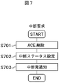
図5は、各機器間での一連の通信シーケンスを示す図、図6、図7、図8は、各々接続処理、中断処理、終了処理のフローチャートを示す図である。なおここで言う「接続/中断」とは、端末とコンピュータユニットの間で通信可能/不可能な状態を意味する。 FIG. 5 is a diagram showing a series of communication sequences between devices, and FIGS. 6, 7, and 8 are flowcharts showing connection processing, interruption processing, and termination processing, respectively. Note that “connection / interruption” here means a state in which communication is possible / impossible between the terminal and the computer unit.
最初に、図5と図6を用いて、ユーザが端末1を操作してコンピュータユニット2へ接続する際の処理を説明する。
First, processing when the user operates the
ユーザは端末1のコンピュータユニット制御プログラム47を操作し、アクセス制御サーバ3に対して接続要求(F501)を送信する。アクセス制御サーバ3の通信制御部6は、接続要求(F501)を受信し、認証処理部7に対してユーザ認証を依頼する。
The user operates the computer
本実施例においては、ユーザ認証方式として、インターネットにおける標準化機関であるIETF(Internet Engineering Task Force)が規格化しているTLS(Transport Layer Security)プロトコルを利用する。TLSはSSL(Secure Sockets Layer)として広く知られた技術であり、公開鍵と秘密鍵の鍵ペアによりデータを暗復号する公開鍵暗号技術と、公開鍵の正当性を保証する公開鍵証明書を用いて、通信者の本人性を検証するとともに、通信データの暗号化を行うプロトコルである。認証する対象として、サーバの本人性を検証するサーバ認証と、クライアントの本人性を検証するクライアント認証が規定されている。クライアント認証を用いる場合は、各ユーザが自分の公開鍵と秘密鍵、そして公開鍵証明書を持つ。これらは、端末1の二次記憶装置46に格納しても良いし、ICカード等、鍵を安全に保管可能な認証デバイス45に格納しても良い。
In the present embodiment, a TLS (Transport Layer Security) protocol standardized by the Internet Engineering Task Force (IETF), which is a standardization organization on the Internet, is used as a user authentication method. TLS is a technology widely known as SSL (Secure Sockets Layer), which uses a public key encryption technology that encrypts / decrypts data using a public key / private key pair, and a public key certificate that guarantees the validity of the public key. Used to verify the identity of the communicator and encrypt the communication data. Server authentication for verifying the identity of the server and client authentication for verifying the identity of the client are defined as objects to be authenticated. When using client authentication, each user has his or her public key, private key, and public key certificate. These may be stored in the
認証処理部7は、上記TLSクライアント認証を用いて、端末1を操作するユーザの本人性を検証する(S601)。その検証結果と、正規のユーザであることが検証できた場合にはユーザの公開鍵証明書に含まれる主体者名(subject)を通信制御部6へ返す。通信制御部6は、コンピュータユニット管理部8に対して、主体者名を渡し、コンピュータユニット2の起動を依頼する(S602)。
The
依頼を受けたコンピュータユニット管理部8は、管理DB10内のユーザ管理テーブル11を検索し、渡された主体者名と同一の値がユーザID13として登録されたユーザエントリを探す。エントリを発見すると、そのユーザが利用する特定のコンピュータユニット2のコンピュータユニットID14とそのステータス16を参照し、そのコンピュータユニット2が起動されているか否かを確認する(S603)。ステータス16の値が「終了(未起動)」である場合は、そのコンピュータユニット2を起動する。
Upon receiving the request, the computer
本実施例においては、コンピュータユニットを起動するために、マジックパケットと呼ばれる技術を用いる。マジックパケットは、ネットワークを介して接続されたコンピュータをリモート起動するための通信パケットであり、LANカード固有のMACアドレスにより、起動するコンピュータを指定する。 In this embodiment, a technique called magic packet is used to start the computer unit. The magic packet is a communication packet for remotely starting a computer connected via a network, and designates the computer to be started by a MAC address unique to the LAN card.
コンピュータユニット管理部8は、コンピュータユニットID14の値を取り出し、コンピュータユニット管理テーブル12から同一の値がコンピュータユニットID17に登録されたコンピュータユニットエントリを探す。そして、発見したエントリのMACアドレス18に登録された値を取り出し、それを含むマジックパケット(F502)を組み立て、ネットワーク5を介してコンピュータユニット2へ送信する(S604)。コンピュータユニット2は起動完了すると、起動完了通知(F503)を返す。コンピュータユニット管理部8は起動完了を確認すると、ユーザエントリ内のIPアドレス15に登録された値を取り出して、通信制御部6へ通知する。
The computer
次に通信制御部6は、受信した接続要求(F501)の通信パケットからソースアドレスを抽出し、コンピュータユニット管理部8から通知されたコンピュータユニット2のIPアドレス15と共にACE設定部9に渡し、ACEの追加設定を依頼する。
Next, the
通信制御部6から依頼を受けたACE設定部9は、図4に示したACEを生成する(S605)。ACEの構成は、具体的には、第1パートが「permit」、第2パートが渡されたソースアドレス、第3パートが渡されたIPアドレスである。次にACE設定部9は、生成したACEを追加設定する要求(F504)を、管理用ポートを介してハブ4に依頼する(S606)。これにより、接続を要求した端末1とそのユーザが利用する特定のコンピュータユニット2間にネットワークリンクが形成される。その後、ACE設定部9は通信制御部6へ制御を返す。
The
通信制御部6は、コンピュータユニット管理部8に対して、ユーザエントリ内のステータス16の値を「接続」に変更するよう依頼する(S607)。その後、接続要求(F501)に対する応答として、コンピュータユニット管理部8から通知されたコンピュータユニット2のIPアドレス15と共に、接続の準備が整ったことを表す接続可通知(F505)を、端末1へ返す(S608)。
The
接続可通知(F505)を受信すると、端末1のコンピュータユニット制御プログラム47は、通知されたIPアドレスをターミナルサービス制御プログラム49に伝達する。ターミナルサービス制御プログラム49はそのIPアドレスを用いて、コンピュータユニット2にターミナルサービス接続要求(F506)を送る。そしてユーザは、ログイン画面にユーザIDとパスワードを入力後、ターミナルサービスの提供を受けて、PC業務を行う。
When the connection permission notification (F505) is received, the computer
上記認証工程(S602)において、認証処理部7が端末1を操作するユーザの本人性を検証できなかった場合には、通信制御部6は、端末1に対して利用不可通知を返し(S609)、何れのコンピュータユニット2に対しても起動やネットワークリンクの設定を行わない。
In the authentication step (S602), when the
次に、図5と図7を用いて、離席時等、ユーザが一時的に端末1から離れる際の中断処理を行う場合を説明する。これは、ユーザが離席している間に、他のユーザがその端末を操作し不正なアクセスを行うことを防止するために有効となる。
Next, with reference to FIGS. 5 and 7, a case will be described in which interruption processing is performed when the user temporarily leaves the
ユーザは端末1から離れる際、端末1のコンピュータユニット制御プログラム47を操作し、アクセス制御サーバ3に対して中断要求(F507)を送信する。アクセス制御サーバ3の通信制御部6は、中断要求(F507)を受信し、ACE設定部9に対してACEの削除を依頼する。
When the user leaves the
通信制御部6から依頼を受けたACE設定部9は、前記接続工程(図6のS606)において追加設定したACEを削除する要求(F508)を、管理用ポートを介してハブ4に依頼する(S701)。これにより、接続中の端末1とそのユーザが利用する特定のコンピュータユニット2間に設定されていたネットワークリンクが解除され、両者の通信は遮断される。ただし、コンピュータユニット2はそのまま起動状態を継続する。その後、ACE設定部9は通信制御部6へ制御を返す。
The
次に通信制御部6は、コンピュータユニット管理部8に対して、ユーザエントリ内のステータス16の値を「中断」に変更するよう依頼(S702)する。そして、中断要求(F507)に対する応答として、中断処理が正常に完了したことを表す中断完通知(F509)を、端末1へ返す(S703)。
Next, the
その後、ユーザは端末1の前に戻り、PC業務を再開する。再開時の処理は、先に図6にて説明した接続要求時と同様であり、端末1のコンピュータユニット制御プログラム47を操作し、アクセス制御サーバ3に対して接続要求(F510)を送信し、再度ユーザ認証とACEの設定を行う。ただし接続対象のコンピュータユニット2はすでに起動状態「中断」にあるので、コンピュータユニット2を起動する工程(S604)をスキップする。生成したACEの追加要求(F511)をハブ4へ送信する(S606)と、中断していた端末1と特定のコンピュータユニット2の間に再びネットワークリンクが形成される。
Thereafter, the user returns to the front of the
接続可通知(F512)を受信した端末1のコンピュータユニット制御プログラム47はターミナルサービス制御プログラム49を起動し、コンピュータユニット2にターミナルサービス接続要求(F513)を送り、ユーザがログイン操作(ユーザIDとパスワードを入力)を行って、PC業務を再開する。
The computer
次に、図5と図8を用いて、帰宅時等、ユーザがPC業務を終了する際の終了処理を説明する。 Next, with reference to FIG. 5 and FIG. 8, a termination process when the user terminates the PC work such as when returning home will be described.
ユーザは、PC業務を終了する際、端末1のコンピュータユニット制御プログラム47を操作し、アクセス制御サーバ3に対して終了要求(F514)を送信する。アクセス制御サーバ3の通信制御部6は、終了要求(F514)を受信し、コンピュータユニット管理部8に対してコンピュータユニット2のシャットダウンを依頼する。
When ending the PC job, the user operates the computer
依頼を受けたコンピュータユニット管理部8は、ネットワーク5を介して、コンピュータユニット2へシャットダウン要求(F515)を送信し(S801)、シャットダウン完了通知(F516)を待つ。シャットダウン完了を確認したコンピュータユニット管理部8は、通信制御部6へ制御を返す。
Upon receiving the request, the computer
通信制御部6は、ACE設定部9に対してACEの削除を依頼する。通信制御部6から依頼を受けたACE設定部9は、設定中のACEを削除する要求(F517)を、管理用ポートを介してハブ4に発行する(S802)。これにより、接続中の端末1と特定のコンピュータユニット2間に設定されていたネットワークリンクが解除され、両者の通信は遮断される。その後、ACE設定部9は通信制御部6へ制御を返す。
The
また通信制御部6は、コンピュータユニット管理部8に対して、ユーザエントリ内のステータス16の値を「終了」に変更するよう依頼(S803)する。そして、終了要求(F514)に対する応答として、シャットダウン処理が正常に完了したことを表す終了完通知(F518)を、端末1へ返す(S804)。
The
次に、図9を用いて、本実施例によるアクセス制御動作とその作用効果、すなわち不正アクセス防止機能について説明する。 Next, with reference to FIG. 9, the access control operation and its operation effect according to the present embodiment, that is, the unauthorized access prevention function will be described.
ネットワーク5に、3台の端末1a,1b,1cと3台のコンピュータユニット2a,2b,2cが接続されている。各端末のIPアドレスを、各々「192.168.4.71」、「192.168.5.48」、「192.168.6.10」とする。一方、各コンピュータユニットのIPアドレスを、各々「192.168.0.2」、「192.168.0.3」、「192.168.0.4」とする。2人のユーザa,bはそれぞれ端末1a,1bを操作し、各々特定のコンピュータユニット2a,2bを利用できるものとする。
Three
端末1aを操作するユーザaが、アクセス制御サーバ3に対して接続要求を送信すると、アクセス制御サーバ3はユーザaの本人性を確認後、ACL20にACE21を追加するよう、ハブ4に依頼する。これにより、端末1aとコンピュータユニット2aの間にネットワークリンクが形成され、通信パケットが送受可能となる。この結果、端末1aを操作するユーザaは、コンピュータユニット2aが提供するターミナルサービスを受けられるようになる。
When the user a operating the terminal 1a transmits a connection request to the
端末1bの場合も同様に、アクセス制御サーバ3が、ハブ4に対してACE22を追加するよう依頼し、端末1bとコンピュータユニット2bの間にネットワークリンクが形成され、端末1bを操作するユーザbは、コンピュータユニット2bが提供するターミナルサービスを受けられるようになる。
Similarly, in the case of the terminal 1b, the
ここで、アクセス制御サーバ3からユーザ認証を受けていない端末1cは、ACL20内の何れのACEとも合致しない。つまり端末1cとコンピュータユニット間には、ネットワークリンクが形成されていないため、他のユーザcが端末1cを操作しても何れのコンピュータユニットにもアクセスできない。また、アクセス制御サーバ3のユーザ認証を受けた端末でも、特定以外のコンピュータユニットにはアクセスできない。例えば端末1bとコンピュータユニット2cの間にはネットワークリンクが形成されていないため、端末1bからコンピュータユニット2cにアクセスできない。さらにコンピュータユニットから他のコンピュータユニットへもアクセスできない。例えば、ユーザbが端末1bからコンピュータユニット2bへターミナルサービス接続した後、コンピュータユニット2bからコンピュータユニット2cへのターミナルサービス接続を試みても、アクセスできない。
Here, the
以上のように本実施例のアクセス制御サービスおよびアクセス制御サーバでは、ユーザ認証した端末と、そのユーザが利用する特定のコンピュータユニットの間にのみ、通信可能なネットワークリンクを設定する。どのユーザがどのコンピュータを利用可能であるかは、予めシステム管理者等が定め、アクセス制御サーバ内に登録しておく。このため、ユーザ認証されていない端末はもちろん、他のユーザにより認証された端末からも、正規ユーザのコンピュータユニットにアクセスできない。つまり、コンピュータユニットに対してターミナルサービス接続を試みても、ハブによりネットワークが遮断されているため、ログイン画面すら表示されず、ログインを試みることはできない。これにより、ブルートフォース攻撃や辞書攻撃、そしてアカウントロックアウト機能を悪用した嫌がらせ行為等のパスワード攻撃を排除でき、さらに、ポートスキャン攻撃やDoS攻撃等の不正アクセスからコンピュータユニットを防御する、安全なアクセス制御サービスを提供可能である。 As described above, in the access control service and the access control server of this embodiment, a communicable network link is set only between a user authenticated terminal and a specific computer unit used by the user. Which user can use which computer is determined in advance by a system administrator or the like and registered in the access control server. For this reason, the computer unit of a legitimate user cannot be accessed from a terminal not authenticated by a user and a terminal authenticated by another user. In other words, even if a terminal service connection is attempted to the computer unit, since the network is blocked by the hub, even the login screen is not displayed and the login cannot be attempted. As a result, brute force attacks, dictionary attacks, and password attacks such as harassment using the account lockout function can be eliminated, and the computer unit can be protected from unauthorized access such as port scan attacks and DoS attacks. Control services can be provided.
なお、本実施例のアクセス制御サーバは、ユーザ認証された端末をそのユーザが操作中(PC業務中)の場合に限り、ネットワークリンクを設定する。操作中断時や操作終了時の場合はネットワークリンクを解除するため、離席時や帰宅時等にも、自分のコンピュータユニットが、他人からパスワード攻撃を受けることはない。また本実施例のアクセス制御サーバは、まず接続要求を送信したユーザを認証し、認証に成功した場合、そのユーザが、現在操作中の端末を認識してその端末を対象としたネットワークリンクを設定する。このため、操作する端末自体もしくは端末が接続されるネットワーク環境は固定されず、例えば、ユーザが外出先や自宅のPCもしくはネットワーク環境を利用する場合等、端末や環境の制限なくターミナルサービスを受けることができる。 Note that the access control server of this embodiment sets a network link only when the user is operating a user-authenticated terminal (PC operation). When the operation is interrupted or the operation is completed, the network link is released, so that the computer unit does not receive a password attack from another person when leaving the desk or returning home. In addition, the access control server of this embodiment first authenticates the user who sent the connection request, and when the authentication is successful, the user recognizes the currently operating terminal and sets a network link for that terminal. To do. For this reason, the terminal itself to be operated or the network environment to which the terminal is connected is not fixed. For example, when a user uses a PC or a network environment at home or at home, the terminal service is received without restrictions on the terminal or environment. Can do.
周知技術によれば、システム管理者は、端末を接続するネットワークのIPアドレスを全てハブのACLに手作業で設定する必要があり、大規模なネットワーク環境においては作業負荷が膨大である。また、端末のIPアドレスがハブのACLに登録されたものであっても、その端末を操作しているのが正当なユーザとは限らない。さらに、正当なユーザがコンピュータユニットを利用していない間、端末のIPアドレス詐称等により、他のユーザがそのコンピュータを不正アクセスできてしまう。本実施例によれば、アクセス制御サーバが端末のIPアドレスを検出し、ハブのACLに自動的に追加するため、システムの保守作業が容易である。また、本実施例のネットワークリンクは、本人性が検証されたユーザに対してのみ提供され、さらに、コンピュータユニットを利用している間のみ提供されるものであり、他のユーザによる不正アクセスからコンピュータユニットを防御可能である。 According to the well-known technique, the system administrator needs to manually set all the IP addresses of the network to which the terminal is connected to the ACL of the hub, and the workload is enormous in a large-scale network environment. Even if the IP address of the terminal is registered in the ACL of the hub, it is not always the right user to operate the terminal. Furthermore, while a legitimate user is not using the computer unit, other users can illegally access the computer due to IP address spoofing of the terminal or the like. According to this embodiment, since the access control server detects the IP address of the terminal and automatically adds it to the ACL of the hub, system maintenance work is easy. In addition, the network link of this embodiment is provided only to a user whose identity has been verified, and is provided only while using a computer unit. Can defend the unit.
上記述べた本実施例は一例であり、以下に述べる各種変形例が可能である。 The above-described embodiment is an example, and various modifications described below are possible.
本実施例のアクセス制御サービスでは、アクセス制御サーバ3とハブ4とを分離して構成している。このため、汎用のハブを採用することができる。これに対し、図10に示すように、アクセス制御サーバをハブと一体化して、アクセス制御サーバ23として構成したアクセス制御サービスも可能である。
In the access control service of this embodiment, the
本実施例のアクセス制御サーバは、ハブの管理用ポートを介してACEの追加や削除を依頼しているが、管理用ポートを備えていない等、ハブの装置仕様によっては、ネットワーク5を介してACEの追加や削除を依頼しても良い。
The access control server according to the present embodiment requests addition or deletion of ACE through the hub management port. However, depending on the device specifications of the hub, such as not having a management port, the access control server may be connected via the
本実施例のアクセス制御サーバは、通信パケットのソース及びデスティネーションアドレスを用いて端末とコンピュータユニットを特定しているが、他の識別情報を用いてこれらの装置を特定しても良い。 The access control server of the present embodiment specifies the terminal and the computer unit using the source and destination address of the communication packet, but may identify these devices using other identification information.
本実施例においては、ネットワークリンクの設定を、ハブの中継可否の制御機能により実現した場合を例示しているが、他の手段を用いても実現可能である。例えば、VLAN(Virtual LAN)等の特定のコンピュータ間にのみ通信を限定できるような機能がハブに搭載されていれば、それを利用して実現しても良い。また、コンピュータユニットにファイアウォール機能が搭載されているならば、ハブを利用しなくても、相応の効果が得られる。コンピュータユニットのファイアウォール機能を利用する場合、アクセス制御サーバが、ハブに対して実施しているACEの追加、削除処理を、コンピュータユニットのファイアウォール機能に対して行うように置き換え、指定したソースアドレスからの通信パケットを受け入れるよう、ファイアウォールに依頼すれば良い。 In this embodiment, the case where the setting of the network link is realized by the control function of whether or not to relay the hub is illustrated, but it can also be realized by using other means. For example, if a function such as VLAN (Virtual LAN) that can limit communication only between specific computers is installed in the hub, it may be realized by using the function. Further, if the computer unit has a firewall function, a corresponding effect can be obtained without using a hub. When using the firewall function of the computer unit, the access control server replaces the ACE addition / deletion processing performed for the hub with the firewall function of the computer unit. Just ask the firewall to accept the communication packet.
尚、本実施例においては、端末のアドレスをソースアドレス、コンピュータユニットのアドレスをデスティネーションアドレスとするACEにより形成するネットワークリンクを説明した。これにより、ユーザ認証された端末から特定のコンピュータユニットへの通信パケットのみがハブ4により中継される。しかし実際は、逆方向、つまり特定のコンピュータユニットからユーザ認証された端末へ通信パケットが送信される場合がある。これに対しては、図6のS605,S606において、図4に示すACEを生成、追加するのと同時に、逆方向のACEも生成、追加すれば良い。具体的には、第1パートが「permit」、第2パートのソースアドレスがコンピュータユニットのアドレス、第3パートのデスティネーションアドレスが端末のアドレスであるACEである。両ACEの追加により、ユーザ認証された端末と特定のコンピュータユニットが双方向で通信可能なネットワークリンクを提供可能である。
In this embodiment, the network link formed by ACE using the terminal address as the source address and the computer unit address as the destination address has been described. Thereby, only the communication packet from the user authenticated terminal to the specific computer unit is relayed by the
本実施例においては、通信パケットのソースアドレスを用いて端末を特定し、ネットワークリンクを提供しているが、端末とハブの間にプロキシーやゲートウェイが介在する場合等、ハブが受信した通信パケットのソースアドレスが、端末によらず全て同じになってしまうケースも考えられる。このようなケースでは、他の手段により端末を特定すれば良い。例えば、ソースアドレスと通信ポート番号の組み合わせにより、端末を特定することもできる。一般のハブ4においては、ACEの第2もしくは第3パートとして、アドレスだけでなく、通信ポート番号も組み合わせた指定が可能である。この場合には、図4に示したACEの第2パートに、ソースアドレスと通信ポート番号を記述すれば良い。
In this embodiment, the terminal is specified by using the source address of the communication packet and the network link is provided. However, when a proxy or gateway is interposed between the terminal and the hub, the communication packet received by the hub is received. There may be a case where the source addresses are all the same regardless of the terminal. In such a case, the terminal may be specified by other means. For example, a terminal can be specified by a combination of a source address and a communication port number. In the
本実施例のアクセス制御サーバは、図4に示したような通信パケットのソースアドレスとデスティネーションアドレスにより、特定の端末と特定のコンピュータユニット間にネットワークリンクを提供しており、特定の端末と特定のコンピュータユニット間ではあらゆる通信パケットを送受可能である。しかし、セキュリティ等を考慮し、端末とコンピュータユニット間の通信パケットを特定のプロトコルのみに限定させたいというニーズも考えられる。このようなニーズを満足するには、図4に示したACEの第3パートに、デスティネーションアドレスと利用を許可する通信プロトコルのポート番号を組み合わせた値を設定すれば良い。例えばターミナルサービスのみに限定する場合は、ターミナルサービスプロトコルのポート番号(例えば3389)を設定する。この場合のネットワークリンクは、ターミナルサービス専用のネットワークリンクと言える。さらに、双方向のネットワークリンクを提供する場合は、逆方向のACEも生成して追加すれば良い。具体的には、第1パートが「permit」、第2パートがコンピュータユニットのアドレスとターミナルサービスプロトコルのポート番号を組み合わせた値、第3パートが端末のアドレスであるACEである。もしくは、第1パートが「permit」、第2パートがコンピュータユニットのアドレス、第3パートが端末のアドレスとターミナルサービス制御プログラムのポート番号を組み合わせた値であるACEでも良い。その場合には、アクセス制御サーバは、端末のターミナルサービス制御プログラムのポート番号を検出するものとする。 The access control server of this embodiment provides a network link between a specific terminal and a specific computer unit by using the source address and the destination address of the communication packet as shown in FIG. All communication packets can be transmitted and received between the computer units. However, considering security and the like, there may be a need to limit communication packets between the terminal and the computer unit to a specific protocol. In order to satisfy such needs, a value combining the destination address and the port number of the communication protocol permitted to be used may be set in the third part of the ACE shown in FIG. For example, when limiting only to the terminal service, a port number (for example, 3389) of the terminal service protocol is set. The network link in this case can be said to be a network link dedicated to terminal services. Furthermore, when a bidirectional network link is provided, a reverse ACE may be generated and added. Specifically, the first part is “permit”, the second part is an ACE in which the address of the computer unit and the port number of the terminal service protocol are combined, and the third part is the address of the terminal. Alternatively, the first part may be “permit”, the second part may be an address of the computer unit, and the third part may be an ACE that is a value obtained by combining the terminal address and the port number of the terminal service control program. In that case, the access control server shall detect the port number of the terminal service control program of the terminal.
本実施例のアクセス制御サーバは、特定の端末と特定のコンピュータユニット間にネットワークリンクを提供しており、特定の端末以外は特定のコンピュータユニットにネットワーク経由でアクセスできない。しかし、コンピュータユニットで、Webサーバ等、他の通信プロトコルを受け入れたいケースも考えられる。 The access control server of the present embodiment provides a network link between a specific terminal and a specific computer unit, and only the specific terminal can access the specific computer unit via the network. However, there may be cases where the computer unit wants to accept other communication protocols such as a Web server.
また、今日のPC業務には、Webやメール等、他のコンピュータと通信するアプリケーションプログラムが欠かせない。本実施例においてはターミナルサービスへの適用を例示したが、この場合、各コンピュータユニットが他のコンピュータと通信する必要がある。これらの他のコンピュータがネットワーク5上に接続されている場合には、ネットワークリンクがアプリケーションプログラムの通信を妨害することのないようにしなければならない。
In today's PC business, application programs that communicate with other computers, such as Web and email, are indispensable. In this embodiment, application to a terminal service has been illustrated, but in this case, each computer unit needs to communicate with another computer. If these other computers are connected on the
上記二つのケースに対応するには、アクセス制御サーバが追加するACEより後の検索順位として、第1パートが「deny」、第2パートが「空き」、第3パートが各コンピュータユニットのアドレス(もしくは「空き」)とターミナルサービスを提供する通信ポート番号を組み合わせたACEを追加する。それと共に、第1パートが「permit」のACEをデフォルトACEとして登録すれば良い。これらのACEは、システム管理者等が、ハブ4に対して予め設定する。これにより、特定の端末以外はターミナルサービスに接続できず、つまりログインを試みることはできないという不正アクセス防御の機能を確保しつつ、コンピュータユニットと他のコンピュータとのターミナルサービス以外の通信を受け入れることができる。
In order to deal with the above two cases, as the search order after the ACE added by the access control server, the first part is “deny”, the second part is “free”, and the third part is the address of each computer unit ( (Or “vacant”) and an ACE that combines a communication port number for providing a terminal service. At the same time, an ACE whose first part is “permit” may be registered as a default ACE. These ACEs are preset for the
しかしながら上記のように設定した場合、コンピュータユニットを起動するマジックパケットも通過させることになり、コンピュータユニットのMACアドレスさえ判明すれば、何れの端末からもコンピュータユニットを不正に起動できる恐れがあり、さらなる対応が必要となる。 However, in the case of setting as described above, the magic packet for starting the computer unit is also passed, and if the MAC address of the computer unit is found, there is a possibility that the computer unit can be illegally started from any terminal. Action is required.
図15は、上記ケースに対応するために、前記図5の通信シーケンスを変形した例である。ここでは、ACEによるパケットのフィルタリングだけでなく、コンピュータユニットが接続されたハブのポートを開閉制御するようにしている。 FIG. 15 shows an example in which the communication sequence of FIG. 5 is modified to deal with the above case. Here, not only filtering of packets by ACE but also opening / closing control of the port of the hub to which the computer unit is connected.
端末1からの接続要求(F701)を受信したアクセス制御サーバ3は、ユーザの本人性を確認し、コンピュータユニット2を起動した後(F702)、ACEを追加するとともに(F704)、そのコンピュータユニット2が接続されたポートを開くよう(F705)、ハブ4に依頼する。また、端末1から終了要求(F715)を受信した場合、コンピュータユニット2をシャットダウンした後(F716)、追加したACEを削除するとともに(F718)、F705において開いたポートを閉じるよう(F719)、ハブ4に依頼する。ハブ4へのポート開閉は、例えばポートの番号で指示する。このため、各コンピュータユニット管理テーブルには、コンピュータユニットが接続されたポートの番号を記憶する領域を設ける。これにより、コンピュータユニット2の不正起動を防止することが可能である。
Upon receiving the connection request (F701) from the
また、ユーザがPC業務を中断している間、コンピュータユニット2が他の機器と通信する必要がなければ、ポートを閉じるように制御を変更しても良い。例えば、端末1からの中断要求(F708)を受信したアクセス制御サーバ3は、F704において追加したACEを削除した後(F709)、F705において開いたポートを閉じるようにハブ4に依頼する。端末1から再び接続要求(F711)を受信した場合、ACEを追加した後(F712)、閉じたポートを開くようにハブ4に依頼する。また、F709の「ACE削除」を「ポート閉」、F712の「ACE追加」を「ポート開」に置き換えても同様の効果が得られる。
Further, when the user interrupts the PC operation, if the
本実施例においては、P2Pタイプのターミナルサービスを例に説明しているが、本実施例はSBCタイプのターミナルサービスにも適応可能である。認証されていないユーザは、SBCタイプのターミナルサービスに接続を試みることすらできない。また、SBCタイプのターミナルサービスは、複数のユーザが1台のコンピュータユニットを共有するものである。1台のコンピュータユニットを共有可能なユーザとして、数十名程度のグループを割り当てるのが適当である。これにより、あるグループに属さないユーザは、特定のコンピュータユニットにはアクセスできない。また、通信データをユーザ毎に識別することで、ユーザ間のプライバシーを保護することができる。本実施例は、さらに、複数のユーザと特定の複数台のコンピュータユニットとの間でのサービス形態に発展させることも可能である。その際、アクセス先のコンピュータユニットを指定するための情報を追加すれば良い。 In this embodiment, a P2P type terminal service is described as an example, but this embodiment can also be applied to an SBC type terminal service. Unauthenticated users cannot even attempt to connect to SBC type terminal services. Further, the SBC type terminal service is one in which a plurality of users share one computer unit. As a user who can share one computer unit, it is appropriate to assign a group of about several tens of people. Thereby, a user who does not belong to a certain group cannot access a specific computer unit. Moreover, privacy between users can be protected by identifying communication data for each user. This embodiment can be further developed into a service form between a plurality of users and a specific plurality of computer units. At this time, information for designating an access destination computer unit may be added.
尚、既知のターミナルサービスは、端末とリモートコンピュータがネットワークを介してデータを授受するため、ネットワーク障害等によりデータを授受できない状態に陥ると、ターミナルサービスの通信セッションは切断される。ユーザは、ネットワークが復旧した後、利用していたリモートコンピュータに対して、再度ターミナルサービス接続することにより、PC業務を再開可能である。しかし、ネットワーク障害によりターミナルサービスが利用できない状況になった際、ユーザが本実施例の中断操作を行うことなく離席すると、ネットワークの復旧後、そのユーザが使用していた端末を用いて、他のユーザによりコンピュータユニットへのパスワード攻撃を受ける恐れがある。 In the known terminal service, since the terminal and the remote computer exchange data via the network, the communication session of the terminal service is disconnected if the data cannot be exchanged due to a network failure or the like. After the network is restored, the user can resume the PC operation by reconnecting the terminal computer to the remote computer that has been used. However, when the terminal service cannot be used due to a network failure, if the user leaves without performing the interruption operation of the present embodiment, after the network is restored, the terminal used by the user is used. Users may be subject to password attacks on computer units.
図16は、上記ケースに対応するために、前記図5の通信シーケンスを変形した例である。ここでは、端末とコンピュータユニット間の通信が不可能となった時点で、形成していたネットワークリンクを解除するものである。 FIG. 16 is an example in which the communication sequence of FIG. 5 is modified to deal with the above case. Here, the network link that has been formed is released when communication between the terminal and the computer unit becomes impossible.
各コンピュータユニット2上では、端末1との通信状態を監視するエージェントを稼働させる。エージェントは、端末1との通信が途絶えたことを検出した場合、その旨をアクセス制御サーバ3へ通知する(F607)。切断通知を受信したアクセス制御サーバ3は、図7に示した手順と同様、F604において追加設定したACEを削除する要求(F608)をハブ4に依頼し、端末1とコンピュータユニット2間に設定されていたネットワークリンクを解除する。これにより、ネットワーク復旧後のコンピュータユニットへの不正アクセスを防止可能である。
On each
また、一般のターミナルサービスクライアント(図13のターミナルサービス制御プログラム49)において、ユーザは、リモートPCとのターミナルサービス通信セッションを切断することが可能である。本実施例においては、ユーザが端末1から離れる際、端末1のコンピュータユニット制御プログラム47を操作し、アクセス制御サーバ3に対して中断要求を送信するものとしている。しかし、中断要求の前に、ユーザがターミナルサービス通信セッションを切断した場合、ネットワークリンクは形成されたままとなる。他の端末がコンピュータユニットにアクセスできるわけではないが、潜在的な不正アクセスに備え、ターミナルサービスを利用していない間はネットワークリンクを解除した方が安全である。これに対応するには、端末1のコンピュータユニット制御プログラム47がリモートPCとのターミナルサービス通信セッションを監視し、切断を検知した場合、アクセス制御サーバ3に対して中断要求を自動送信する処理を追加すれば良い。
Further, in a general terminal service client (terminal
本実施例においては、コンピュータユニットに対する不正アクセスをハブで遮断している。ハブで遮断した不正アクセスに関する情報(端末のIPアドレス、通信パケット、プロトコル等)をシステム管理者に通知するようにしておけば、システム管理者は不正アクセスに対する対策を即座に実施でき、さらに安全なシステムを構築可能である。システム管理者への不正アクセス通知は、ハブの機能を利用しても良いし、ハブが備えていなければ、アクセス制御サーバがハブのログ等から情報を抽出し、それをシステム管理者に通知する手段を追加しても良い。 In this embodiment, unauthorized access to the computer unit is blocked by the hub. If the system administrator is notified of information related to unauthorized access blocked by the hub (terminal IP address, communication packet, protocol, etc.), the system administrator can immediately implement countermeasures against unauthorized access, making it safer. A system can be constructed. For the unauthorized access notification to the system administrator, the function of the hub may be used. If the hub is not provided, the access control server extracts information from the hub log etc. and notifies the system administrator of the information. Means may be added.
本実施例のアクセス制御サーバは、ユーザ認証手段としてTLSを利用しているが、本人性を検証可能であれば、他の手段を用いても良い。例えば、指紋や虹彩、指静脈等、人間固有の特徴を利用する生体認証なども有効である。 The access control server of this embodiment uses TLS as a user authentication means, but other means may be used as long as the identity can be verified. For example, biometric authentication using human-specific features such as fingerprints, irises, and finger veins is also effective.
本実施例におけるコンピュータユニットは、CPU、ハードディスク、LANカード等が筐体内に搭載された、汎用のPC等である。しかし、本実施例におけるコンピュータユニットの役割はターミナルサービスの提供であり、筐体は必ずしも必要ではなく、CPU、ハードディスク、LANカード等が実装された基板だけでも良い。このような基板は、一般にブレードコンピュータと称される。ブレードコンピュータは様々なシステムに導入され始めており、本実施例のコンピュータユニットとして適用することも可能である。 The computer unit in this embodiment is a general-purpose PC or the like in which a CPU, a hard disk, a LAN card, and the like are mounted in a housing. However, the role of the computer unit in this embodiment is to provide a terminal service, and the housing is not necessarily required, and only a substrate on which a CPU, a hard disk, a LAN card, and the like are mounted may be used. Such a substrate is generally called a blade computer. Blade computers have begun to be introduced into various systems, and can be applied as computer units in this embodiment.
本実施例においては、コンピュータユニットの起動をマジックパケットにより実現する場合を例示しているが、他の手段を用いても実現可能である。例えば、コンピュータユニットがIPMI(Intelligent Platform Management Interface)をサポートしていれば、それを利用しても実現できる。 In the present embodiment, the case where the activation of the computer unit is realized by a magic packet is illustrated, but it can also be realized by using other means. For example, if the computer unit supports IPMI (Intelligent Platform Management Interface), it can also be realized by using it.
尚、本実施例のアクセス制御サーバは、端末からの接続要求を受けてコンピュータユニットの稼働状況を確認し、未起動の場合は起動し、起動が完了した後端末へターミナルサービスへの接続準備完了を通知する。これを受けて端末は、コンピュータユニットへのターミナルサービス接続を開始する。しかし、通常のコンピュータユニットの起動には数十秒から数分かかるため、コンピュータユニットが起動中であることを、ユーザに知らせるほうが好ましい。これに対応するには、コンピュータユニットの起動(図6のS604)の前に、コンピュータユニットが起動中であることを端末1に対して通知する処理を追加すれば良い。端末1は、その通知を受けた際、「ただいまPCを起動中です。しばらくお待ち下さい。」等のメッセージをディスプレイ42に表示する。
The access control server of this embodiment receives a connection request from the terminal, checks the operating status of the computer unit, starts if not started, and completes preparation for connection to the terminal service to the terminal after the startup is completed. To be notified. In response, the terminal initiates a terminal service connection to the computer unit. However, since it usually takes several tens of seconds to several minutes to start up the computer unit, it is preferable to inform the user that the computer unit is starting up. To cope with this, a process of notifying the
本実施例において、各コンピュータユニットのIPアドレスは、管理者が予め管理DBに登録するものとしており、これは、各コンピュータユニットに対して固定のIPアドレスを割り当てる運用形態を想定している。一方、各コンピュータユニットに対してIPアドレスを動的に割り当てる運用形態も考えられる。この形態では、一般にDHCP(Dynamic Host Configuration Protocol)サーバが利用される。本実施例を動的なIPアドレスに対応させるには、IPアドレスを通知するプログラムを各コンピュータユニットに搭載すれば良い。そのプログラムは、コンピュータユニットの起動毎に実行され、DHCPサーバにより割り当てられたIPアドレスを検出して、アクセス制御サーバに通知する。通知を受けたアクセス制御サーバは、管理DBのIPアドレス領域に値を格納し、以降の処理において参照する。 In this embodiment, the IP address of each computer unit is assumed to be registered in advance in the management DB by the administrator, and this assumes an operation mode in which a fixed IP address is assigned to each computer unit. On the other hand, an operation mode in which an IP address is dynamically assigned to each computer unit is also conceivable. In this form, a DHCP (Dynamic Host Configuration Protocol) server is generally used. In order to make this embodiment correspond to a dynamic IP address, a program for notifying the IP address may be installed in each computer unit. The program is executed every time the computer unit is activated, detects the IP address assigned by the DHCP server, and notifies the access control server. The access control server that has received the notification stores the value in the IP address area of the management DB and refers to it in the subsequent processing.
なお、本実施例においては、アクセス制御サーバが1台の構成を説明したが、無停止運転等の高信頼なシステムを構築するには、アクセス制御サーバを2台以上に冗長化すれば良い。そして、稼働中のサーバが装置の障害等により不能となった場合、他のサーバに切り換え、サービスを継続できるようにすれば良い。また、ユーザ数が多い大規模システム等、1台のアクセス制御サーバでは処理能力が不足する場合は、複数台のアクセス制御サーバを稼働させ、並列運用すれば良い。この場合、各端末は負荷の最も少ないアクセス制御サーバに対して要求を送信するか、もしくはアクセス制御サーバとネットワークの間に負荷分散装置を設置することにより、アクセス制御サーバの負荷を平準化することが可能である。 In the present embodiment, the configuration of one access control server has been described. However, in order to construct a highly reliable system such as non-stop operation, the access control server may be made redundant to two or more. Then, when an operating server becomes impossible due to a device failure or the like, it may be switched to another server so that the service can be continued. In addition, when a single access control server has insufficient processing capability, such as a large-scale system with a large number of users, a plurality of access control servers may be operated and operated in parallel. In this case, each terminal sends a request to the access control server with the least load, or installs a load balancer between the access control server and the network to equalize the load on the access control server. Is possible.
図11は、本発明によるアクセス制御サービスを実行するコンピュータシステムの第2の実施例を示す構成図である。本実施例は、各コンピュータユニットが大容量のハードディスクを共有する構成である。第1の実施例との異なる点は、各ユーザは特定のコンピュータユニットを専有するのではなく、ハードディスクに、専有の領域を設けたものである。本実施例のシステムでは、ユーザの使用するコンピュータユニットを共有しているので、少ない台数のコンピュータユニットで効率的な運用を可能とするものである。 FIG. 11 is a block diagram showing a second embodiment of the computer system for executing the access control service according to the present invention. In this embodiment, each computer unit shares a large-capacity hard disk. The difference from the first embodiment is that each user does not occupy a specific computer unit but provides a dedicated area on the hard disk. In the system of this embodiment, since the computer unit used by the user is shared, efficient operation is possible with a small number of computer units.
1台以上(ここでは2台)のコンピュータユニット2(2a、2b)を大容量のハードディスク24に接続する。ハードディスク24は、登録したユーザ(ここでは3人、a、b、c)毎に領域を分割し、各領域(24a、24b、24c)には、各ユーザが利用するOSや業務に使用するアプリケーション等のソフトウェア及びデータを格納する。ユーザ(例えばユーザa)が利用を始める際は、ハードディスク24上のユーザ領域(24a)をマウントし、そのユーザ領域に格納されたOSによりコンピュータユニット2を起動する。その際に使用するコンピュータユニット2は、空き状態の何れかのコンピュータユニット2を動的に割り当てる。本実施例の場合は、コンピュータユニット2とハードディスク24を分離しているため、利用するユーザに対して、コンピュータユニット2を静的に割り当てる必要がない。
One or more (two in this case) computer units 2 (2a, 2b) are connected to the large-capacity
図12は、本実施例におけるアクセス制御サーバ3が有する管理データベース30の情報の一例を示す図である。ユーザ管理テーブル31のユーザエントリに、ハードディスク24上のユーザ領域を示すマウント情報37と、コンピュータユニット管理テーブル32のコンピュータユニットエントリに、コンピュータユニット2のステータス情報(稼動/空き)40を加える。ユーザエントリのマウント情報37は、ユーザ登録時等に、システム管理者が情報を登録する。コンピュータユニットエントリのステータス情報40は、システム導入時等に「空き」に初期化される。一方、ユーザエントリ内のコンピュータユニットID34は、アクセス制御サーバ3が値を設定するため、システム管理者が事前登録する必要はない。本実施例では、使用するコンピュータユニットの台数を、ユーザ数以下の台数としてサービスを行うことができる。あるいは、使用するコンピュータユニットの台数は、ネットワークに接続される端末1の台数以下となる。
FIG. 12 is a diagram illustrating an example of information in the
本実施例のアクセス制御サービスの接続処理フローについて説明する。なお、前記第1の実施例と共通の部分については、前記図面(図5、図6)も参照して説明する。アクセス制御サーバ3はユーザ認証(S601)の結果、正規のユーザであることを検証すると、コンピュータユニット管理部8は、ハードディスク24のマウントとコンピュータユニット2の起動(S604)を行う。
A connection processing flow of the access control service of this embodiment will be described. The parts common to the first embodiment will be described with reference to the drawings (FIGS. 5 and 6). When the
まず、コンピュータユニット管理テーブル32を検索し、ステータス情報40として「空き」が登録されたコンピュータユニットエントリを探し、そのエントリのステータス情報40を「稼動」に変更して、今回使用するコンピュータユニットとして決定する。次に、ユーザ管理テーブル31を検索し、認証したユーザが登録されているユーザエントリを探し、そこに登録されたマウント情報37の値を取り出す。そして、上記使用するコンピュータユニット2に対して、上記マウント情報37に基づきハードディスク24をマウントするよう指示する。そして、MACアドレス39に登録された値を取り出しマジックパケット(F502)を組み立て、上記コンピュータユニット2へ送信して起動させる。
First, the computer unit management table 32 is searched, a computer unit entry in which “free” is registered as the
コンピュータユニット管理部8は起動完了通知(F503)を受けると、コンピュータユニットエントリ内のコンピュータユニットID38に登録された値を、ユーザエントリ内のコンピュータユニットID34に登録した後、IPアドレス35に登録された値を取り出して、通信制御部6へ渡す。
When the computer
通信制御部6は、受信した通信パケットから接続を要求した端末1のソースアドレスを抽出し、コンピュータユニット管理部8から通知された使用するコンピュータユニット2のIPアドレス35と共にACE設定部(リンク設定部)9に渡す。ACE設定部9はACEを生成し(S605)、ACEを追加設定する要求(F504)をハブ4に依頼する(S606)。ACEの構成は、前記実施例1と同様である。これにより、接続を要求した端末1とコンピュータユニット2間にネットワークリンクが形成される。その結果、ユーザは、ログイン実行後、ハードディスクの特定のユーザ領域をマウントしたコンピュータユニット2からターミナルサービスの提供を受けて、PC業務を行うことができる。PC業務の中断、終了の処理も、実施例1と同様に行う。
The
以上のように本実施例においては、ユーザ認証した端末と、そのユーザが利用する特定のコンピュータユニットの間にのみ、通信可能なネットワークリンクを設定する。これにより、パスワード攻撃を排除でき、安全なアクセス制御サービスを提供可能である。 As described above, in this embodiment, a communicable network link is set only between a user authenticated terminal and a specific computer unit used by the user. As a result, password attacks can be eliminated and a secure access control service can be provided.
さらに本実施例では、各コンピュータユニットは大容量のハードディスクを共有するため、必ずしも個々のコンピュータユニットがハードディスクを備える必要はない。また、利用するユーザに対して、空き状態のコンピュータユニットを動的に割り当てるため、コンピュータリソースを有効活用可能である。すなわち、コンピュータユニットの台数は、同時に利用するユーザ数だけあれば良い。また一部のコンピュータユニットに障害が発生しても、すぐに代用のコンピュータユニットを割り当てることができるので、システム規模の縮小と信頼性の向上を図ることができる。 Furthermore, in this embodiment, since each computer unit shares a large-capacity hard disk, each computer unit does not necessarily have a hard disk. In addition, since a computer unit in an empty state is dynamically allocated to a user to use, computer resources can be effectively used. That is, the number of computer units need only be the number of users to be used simultaneously. In addition, even if a failure occurs in some computer units, a substitute computer unit can be assigned immediately, so that the system scale can be reduced and the reliability can be improved.
本発明の他の実施例として、上記第1、第2の実施例を組み合わせた形態も可能である。すなわち、各コンピュータユニットは大容量のハードディスクを共有し、各ユーザは、特定のコンピュータユニットと、ハードディスク内の特定の領域を専有するものである。 As another embodiment of the present invention, a combination of the first and second embodiments is possible. That is, each computer unit shares a large-capacity hard disk, and each user occupies a specific computer unit and a specific area in the hard disk.
また本実施例においては、接続を要求したユーザに対して空き状態の何れかのコンピュータユニットを動的に割り当てている。しかし、例えば故障したコンピュータユニットやネットワークの障害により通信不可能なコンピュータユニットは、空き状態であっても、割り当てる対象から除外すべきである。ネットワーク障害の要因としては、ハブ自体もしくはハブ内の一つのポートの故障や、ハブとコンピュータユニットを接続するケーブルの断線や外れ等が挙げられる。さらに、システム管理者の判断により、あるコンピュータユニットを割り当て対象から除外できるようにしても良い。このようにコンピュータユニットを割り当てることにより、ユーザに対して快適に利用可能なコンピュータユニットを提供できる。 In this embodiment, any computer unit that is free is dynamically assigned to the user who requested the connection. However, for example, a failed computer unit or a computer unit that cannot communicate due to a network failure should be excluded from being assigned even if it is idle. Factors of network failure include failure of the hub itself or one port in the hub, disconnection or disconnection of a cable connecting the hub and the computer unit, and the like. Furthermore, a computer unit may be excluded from allocation targets based on the judgment of the system administrator. By assigning computer units in this way, it is possible to provide a computer unit that can be comfortably used by the user.
図17は、本発明によるアクセス制御サービスを実行するコンピュータシステムの第3の実施例を示す構成図である。本実施例は、各端末がネットワークを介して大容量のハードディスク(記憶装置)を共有する構成である。第2の実施例(図11)と同様、ハードディスクは、登録したユーザ毎に領域を分割し、各領域には、各ユーザが利用するOSや業務に使用するアプリケーション等のソフトウェア及びデータを格納している。第2の実施例においては、各コンピュータユニットがハードディスクを共有し、端末はターミナルサービスを用いてコンピュータユニットに接続する構成であったのに対し、本実施例では、コンピュータユニットを廃止し、各端末がハードディスクを共有する構成である。つまり、本実施例においては、OSやアプリケーション等のソフトウェア及びデータはリモートのハードディスクに格納されるが、ソフトウェアを実行するのは端末のCPUであって、ターミナルサービスを利用しないシステムである。本実施例の構成では、第1もしくは第2の実施例のコンピュータユニットが不要となり、システムの導入コストを低減可能である。反面、ハードディスクに対するデータの読み込みや書き込みが全てネットワーク5を介して行われるため、各端末からハードディスクへのアクセス頻度が多量の場合は、高速なネットワークが必要となる。
FIG. 17 is a block diagram showing a third embodiment of the computer system for executing the access control service according to the present invention. In this embodiment, each terminal shares a large-capacity hard disk (storage device) via a network. As in the second embodiment (FIG. 11), the hard disk divides the area for each registered user, and each area stores software and data such as an OS used by each user and an application used for business. ing. In the second embodiment, each computer unit shares a hard disk and the terminal is connected to the computer unit using a terminal service, whereas in this embodiment, the computer unit is abolished and each terminal is connected. Is a configuration for sharing a hard disk. That is, in this embodiment, software and data such as an OS and applications are stored in a remote hard disk, but the software is executed by a terminal CPU and does not use a terminal service. In the configuration of this embodiment, the computer unit of the first or second embodiment is not necessary, and the introduction cost of the system can be reduced. On the other hand, since reading and writing of data to and from the hard disk are all performed via the
図18は、本実施例におけるアクセス制御サーバ3が有する管理データベース51の情報の一例を示す図である。ユーザ管理テーブル52の各ユーザエントリに記憶する情報は、そのユーザを一意に識別するユーザID53、ハードディスク24上のユーザ領域のステータス(稼動状況、接続/中断/終了)54、ハードディスク24上のユーザ領域を示すマウント情報55などである。
FIG. 18 is a diagram illustrating an example of information in the
図19は、本実施例における各機器間での一連の通信シーケンスを示す図である。 FIG. 19 is a diagram illustrating a series of communication sequences between devices in the present embodiment.
ユーザは端末1を操作し、アクセス制御サーバ3に対して接続要求(F801)を送信する。接続要求を受信したアクセス制御サーバ3はユーザ認証を実施し、ユーザの本人性を検証できた場合には、ハブ4に対してACEの追加を依頼する(F802)。ACEの構成は、具体的には、第1パートが「permit」、第2パートが端末のIPアドレス、第3パートがハードディスクのIPアドレスである。尚、ハブ4に接続される機器が単一のハードディスク24である場合、第3パートは「空き」でも良い。次にアクセス制御サーバ3は、接続要求を発行したユーザのユーザエントリを探し、ステータス54を変更するとともに、マウント情報55の値を取り出し、端末1へ通知する(F803)。端末1は、アクセス制御サーバ3から通知されたユーザ領域を示すマウント情報を用いて、ハードディスク24に対してマウントを要求する(F804)。マウントの完了後、端末1は、ハードディスクに格納されたOSを読み込んで起動する。以後ユーザは、リモートのハードディスク24のユーザ専有領域に対してアクセスして、アプリケーションの実行、データの読み出し/書き込み等の処理を実行する。
The user operates the
ユーザは、PC業務を終了する際、端末1を操作し、まずハードディスク24に対してマウントの解除を要求し(F805)、次にアクセス制御サーバ3に対して終了要求(F806)を送信する。終了要求を受信したアクセス制御サーバ3は、ハブ4に対してACEの削除を依頼し(F807)、完了した後、端末1へ終了完了を通知する(F808)。
When ending the PC operation, the user operates the
以上のように本実施例のアクセス制御サービスおよびアクセス制御サーバによれば、ユーザ認証した端末にのみ、共有するハードディスク上のユーザ専有領域と通信可能なネットワークリンクを設定する。ユーザ認証されていない端末は、ハードディスクへのアクセスを、ネットワークレベルで遮断されているため、各ユーザのデータを安全に保護することができる。 As described above, according to the access control service and the access control server of this embodiment, a network link that can communicate with a user-exclusive area on a shared hard disk is set only for a user authenticated terminal. Since a terminal that is not user-authenticated is blocked from accessing the hard disk at the network level, each user's data can be safely protected.
本実施例においては、各端末が単一のハードディスクを共有するケースを例示した。しかし、ユーザ数やユーザ毎に割り当てるディスク領域等によっては、複数のハードディスクを設置することも可能である。例えばユーザ数が500名で、各ユーザに20ギガバイトの領域を割り当てる場合、1テラバイトの領域を備えるハードディスクを10台設置し、ユーザにより使い分ける必要がある。これに対応するには、マウント情報55に、そのユーザが使用するハードディスクのIPアドレスとユーザ領域を示す情報を登録し、ユーザ認証した端末とそのユーザが使用するハードディスクとの間にネットワークリンクを形成すれば良い。 In this embodiment, the case where each terminal shares a single hard disk has been illustrated. However, depending on the number of users and the disk area allocated for each user, a plurality of hard disks can be installed. For example, when the number of users is 500 and an area of 20 gigabytes is allocated to each user, it is necessary to install 10 hard disks each having an area of 1 terabyte and use them according to the user. To cope with this, information indicating the IP address and user area of the hard disk used by the user is registered in the mount information 55, and a network link is formed between the user authenticated terminal and the hard disk used by the user. Just do it.
1…端末、2…コンピュータユニット、3…アクセス制御サーバ、4…ハブ、5…ネットワーク、6…通信制御部、7…認証処理部、8…コンピュータユニット管理部、9…ACE設定部、10,30,51…管理DB、11,31,52…ユーザ管理テーブル、12,32…コンピュータユニット管理テーブル、19,21,22…ACE、24…ハードディスク、40,56…CPU、41,57…メモリ、42,58…ディスプレイ、43,59…キーボード、45…認証デバイス、46,61…二次記憶装置、47…コンピュータユニット制御プログラム、48…認証制御プログラム、49…ターミナルサービス制御プログラム、50,64…通信制御プログラム、62,63…ネットワークI/F、65…認証処理プログラム、66…コンピュータユニット管理プログラム、67…ACE設定プログラム。
DESCRIPTION OF
Claims (11)
順位付けされた複数の中継可否情報が設定可能であり,
受信したパケットについて,前記順位に従った複数の前記中継可否情報との照合を行い,中継可否を決定する手段と,
予め前記複数のコンピュータユニットのアドレスを含むパケットの遮断を指示する第一の中継可否情報を設定する手段と,
前記クライアントの使用者と,前記使用者が使用するコンピュータユニットを示す接続要求先識別子と,前記コンピュータユニットのアドレスと,当該コンピュータユニットの稼働状況を示す情報を含むステータスとを対応付けたエントリを管理する管理テーブルと,を備え,
いずれかの前記クライアントから接続要求を受信したら,前記接続を要求するクライアントの使用者の認証を行い,
前記認証に成功したら,前記管理テーブルを参照して,前記接続要求の送信元であるクライアントからのパケット送信を許可するいずれか一つのコンピュータユニットを,前記クライアントの前記使用者に基づいて選択し,
前記選択したコンピュータユニットが起動済みであることを確認した後に,
前記選択したコンピュータユニットを示す接続要求先識別子と,前記選択したコンピュータユニットに接続するクライアントを示す接続元要求識別子と、を含む第二の中継可否情報を,前記第一の中継可否情報より高い順位で設定し,
前記第二の中継可否情報を設定した後に,前記選択したコンピュータユニットを示す接続先識別子を,前記接続を要求するクライアントに通知し,
前記コンピュータユニットに接続したクライアントと前記管理サーバ以外から,前記選択したコンピュータユニットへの接続を,前記中継装置に遮断させ,
前記選択したコンピュータユニットに接続したクライアントから,前記選択したコンピュータユニット以外への接続を,前記中継装置に遮断させることを特徴とする管理サーバ。 A management server connected to a plurality of clients and a relay device that relays packets in communication of a plurality of computer units connected from the clients ;
Multiple relayability information can be set that is ranked,
The received packet matches it to a plurality of the relay availability information in accordance with the order, means for determining whether to relay,
Means for setting first relay enable / disable information for instructing blocking of a packet including addresses of the plurality of computer units in advance;
Manage entries that associate the user of the client, the connection request destination identifier indicating the computer unit used by the user, the address of the computer unit, and the status including information indicating the operating status of the computer unit. A management table, and
After receiving a connection request from one of the client authenticates the user of the client requesting the connection,
When the authentication is successful , referring to the management table, select any one computer unit that permits packet transmission from the client that is the transmission source of the connection request based on the user of the client ,
After the selected computer unit has confirmed that already started,
The second relayability information including the connection request destination identifier indicating the selected computer unit and the connection source request identifier indicating the client connected to the selected computer unit is ranked higher than the first relayability information. Set with
After setting the second relay availability information, a connection destination identifier indicating the selected computer unit is notified to the client requesting the connection ,
The relay device blocks the connection to the selected computer unit from a client other than the management server and the client connected to the computer unit ,
A management server characterized in that the relay device blocks connections from clients connected to the selected computer unit to connections other than the selected computer unit.
前記接続要求先識別子はパケットの送信先識別子であり,前記接続要求元識別子はパケットの送信元識別子であり,
該送信先識別子が前記接続要求の送信元である前記クライアントを示し,該送信元識別子が前記選択したコンピュータユニットを示すパケットの中継を前記パケット中継装置に指示する第三の中継可否情報を,前記第一の中継可否情報より高い順位を与えて設定することを前記パケット中継装置に指示することを特徴とする管理サーバ。 The management server according to claim 1,
The connection request destination identifier is a packet transmission destination identifier; the connection request source identifier is a packet transmission source identifier;
The transmission destination identifier indicates the client that is the transmission source of the connection request, and third relay permission / inhibition information that instructs the packet relay device to relay a packet whose transmission source identifier indicates the selected computer unit, A management server that instructs the packet relay apparatus to give and set a higher order than the first relay availability information.
前記選択したコンピュータユニットが起動済みでなかった場合には,前記選択したコンピュータユニットに起動を要求し,
前記選択したコンピュータユニットの起動完了通知を受信した場合に,前記起動済みであると判断することを特徴とする管理サーバ。 The management server according to claim 1 or 2,
If the selected computer unit has not been started, the selected computer unit is requested to start,
A management server that determines that the computer has been activated when it receives a notification of completion of activation of the selected computer unit.
前記クライアントから前記選択したコンピュータユニットへの接続の中断要求を受けた場合に,前記第二の中継可否情報の削除を前記パケット中継装置に指示し,
前記選択したコンピュータユニットは,前記起動状態を継続することを特徴とする管理サーバ。 A management server according to any one of claims 1 to 3,
Instructing the packet relay device to delete the second relay availability information when receiving a request for interrupting the connection to the selected computer unit from the client;
The management server characterized in that the selected computer unit continues the activated state.
前記クライアントから前記選択したコンピュータユニットへの接続の終了要求を受けた場合に,前記コンピュータユニットがシャットダウンしたことを確認した後に,前記第二の中継可否情報の削除を前記パケット中継装置に指示することを特徴とする管理サーバ。 A management server according to any one of claims 1 to 3,
Instructing the packet relay apparatus to delete the second relayability information after confirming that the computer unit has been shut down when receiving a connection termination request from the client to the selected computer unit Management server characterized by
前記第一乃至第三のいずれか1つの中継可否情報の,前記選択したコンピュータユニットの送信先識別子又は送信元識別子は,前記選択したコンピュータユニットのアドレスと通信プロトコルのポート番号の組み合わせであることを特徴とする管理サーバ。 A management server according to any one of claims 2 to 5,
The transmission destination identifier or transmission source identifier of the selected computer unit in any one of the first to third relayability information is a combination of the address of the selected computer unit and the port number of the communication protocol. A featured management server.
前記コンピュータユニットに係わる前記第一の中継可否情報の前記送信先識別子は,特定の通信プロトコルのポート番号を更に含み,
前記第一の中継可否情報で特定されなかったパケットの中継を前記パケット中継装置に指示する第四の中継可否情報が,前記第一の中継可否情報より低い順位が与えられて,前記パケット中継装置に予め設定されていることを特徴とする管理サーバ。 A management server according to any one of claims 2 to 5,
The transmission destination identifier of the first relay availability information relating to the computer unit further includes a port number of a specific communication protocol,
The fourth relay availability information that instructs the packet relay device to relay a packet not specified by the first relay availability information is given a lower rank than the first relay availability information, and the packet relay device A management server characterized in that it is set in advance.
前記コンピュータユニットと前記クライアントとの通信が途絶えた場合に,前記コンピュータユニットの備える前記クライアントとの通信状態の監視手段から通知を受信し,
前記第二の中継可否情報の削除を前記パケット中継装置に指示することを特徴とする管理サーバ。 A management server according to any one of claims 1 to 7,
When communication between the computer unit and the client is interrupted, a notification is received from the communication state monitoring means with the client included in the computer unit;
A management server that instructs the packet relay device to delete the second relayability information.
前記管理テーブルの初期化時に,前記ステータスとして「終了(未起動)」を設定し, When the management table is initialized, the status is set to “Finished (not activated)”
前記選択したコンピュータユニットが起動し,前記第二の中継可否情報を設定した後に,当該コンピュータユニットに係わるエントリの前記ステータスとして「接続」を設定することを特徴とする管理サーバ。 A management server, wherein after the selected computer unit is activated and the second relay availability information is set, “connection” is set as the status of the entry relating to the computer unit.
前記第二の中継可否情報の削除を前記パケット中継装置に指示した場合には,前記管理テーブルの前記コンピュータユニットに係わるエントリの前記ステータスとして「中断」を設定することを特徴とする管理サーバ。 A management server, wherein when the packet relay device is instructed to delete the second relayability information, “suspend” is set as the status of the entry related to the computer unit in the management table.
前記第二の中継可否情報の削除を前記パケット中継装置に指示した場合には,前記管理テーブルの前記コンピュータユニットに係わるエントリの前記ステータスとして「終了(未起動)」を設定することを特徴とする管理サーバ。 When the packet relay apparatus is instructed to delete the second relayability information, “end (not activated)” is set as the status of the entry related to the computer unit in the management table. Management server.
Priority Applications (2)
| Application Number | Priority Date | Filing Date | Title |
|---|---|---|---|
| JP2005296167A JP4168052B2 (en) | 2005-04-01 | 2005-10-11 | Management server |
| US11/363,508 US20060224897A1 (en) | 2005-04-01 | 2006-02-28 | Access control service and control server |
Applications Claiming Priority (2)
| Application Number | Priority Date | Filing Date | Title |
|---|---|---|---|
| JP2005105835 | 2005-04-01 | ||
| JP2005296167A JP4168052B2 (en) | 2005-04-01 | 2005-10-11 | Management server |
Publications (3)
| Publication Number | Publication Date |
|---|---|
| JP2006309698A JP2006309698A (en) | 2006-11-09 |
| JP2006309698A5 JP2006309698A5 (en) | 2007-06-07 |
| JP4168052B2 true JP4168052B2 (en) | 2008-10-22 |
Family
ID=37072020
Family Applications (1)
| Application Number | Title | Priority Date | Filing Date |
|---|---|---|---|
| JP2005296167A Expired - Fee Related JP4168052B2 (en) | 2005-04-01 | 2005-10-11 | Management server |
Country Status (2)
| Country | Link |
|---|---|
| US (1) | US20060224897A1 (en) |
| JP (1) | JP4168052B2 (en) |
Families Citing this family (21)
| Publication number | Priority date | Publication date | Assignee | Title |
|---|---|---|---|---|
| KR101158092B1 (en) * | 2005-09-30 | 2012-06-22 | 주식회사 케이티 | System for controlling and managing network appratus and method thereof |
| US8151339B2 (en) * | 2005-12-23 | 2012-04-03 | Avaya, Inc. | Method and apparatus for implementing filter rules in a network element |
| JP2008015786A (en) * | 2006-07-06 | 2008-01-24 | Hitachi Ltd | Access control system and access control server |
| JP4789819B2 (en) | 2007-01-31 | 2011-10-12 | 株式会社日立製作所 | Application and data management method, management system, thin client terminal used therefor, management server, and remote computer |
| US8732800B1 (en) * | 2007-03-26 | 2014-05-20 | Jerry Askew | Systems and methods for centralized management of policies and access controls |
| JP4966753B2 (en) * | 2007-06-08 | 2012-07-04 | 株式会社日立製作所 | Information processing system and information processing method |
| US8195806B2 (en) * | 2007-07-16 | 2012-06-05 | International Business Machines Corporation | Managing remote host visibility in a proxy server environment |
| JP5241181B2 (en) * | 2007-09-11 | 2013-07-17 | キヤノン株式会社 | Service control apparatus and method |
| US8676998B2 (en) * | 2007-11-29 | 2014-03-18 | Red Hat, Inc. | Reverse network authentication for nonstandard threat profiles |
| US8234695B2 (en) * | 2007-12-21 | 2012-07-31 | International Business Machines Corporation | Network security management for ambiguous user names |
| JP5305864B2 (en) * | 2008-11-28 | 2013-10-02 | ソフトバンクモバイル株式会社 | Information processing apparatus, information processing method, and information processing program |
| JP5218003B2 (en) | 2008-12-12 | 2013-06-26 | 株式会社リコー | Image forming apparatus, authentication method, and program |
| US8321916B2 (en) * | 2008-12-19 | 2012-11-27 | Intel Corporation | Method, apparatus and system for remote management of mobile devices |
| EP2405650A1 (en) * | 2010-07-09 | 2012-01-11 | Nagravision S.A. | A method for secure transfer of messages |
| US8140733B2 (en) * | 2010-08-12 | 2012-03-20 | Emcon Emanation Control Ltd. | Secure external computer hub |
| EP2610756A4 (en) * | 2010-08-27 | 2014-03-26 | Fujitsu Ltd | SESSION ESTABLISHING APPARATUS, SESSION SETTING METHOD, AND SESSION SETTING PROGRAM |
| JP5750972B2 (en) * | 2011-03-25 | 2015-07-22 | 富士ゼロックス株式会社 | Information processing apparatus, program, and information processing system |
| US9218462B2 (en) * | 2012-04-25 | 2015-12-22 | Hewlett Packard Enterprise Development Lp | Authentication using lights-out management credentials |
| US10015153B1 (en) * | 2013-12-23 | 2018-07-03 | EMC IP Holding Company LLC | Security using velocity metrics identifying authentication performance for a set of devices |
| JP2016167184A (en) * | 2015-03-10 | 2016-09-15 | 日本電気株式会社 | Remote terminal, relay device, authentication control system, remote connection method, and program |
| CN110413215B (en) * | 2018-04-28 | 2023-11-07 | 伊姆西Ip控股有限责任公司 | Method, apparatus and computer program product for obtaining access rights |
Family Cites Families (13)
| Publication number | Priority date | Publication date | Assignee | Title |
|---|---|---|---|---|
| US6233686B1 (en) * | 1997-01-17 | 2001-05-15 | At & T Corp. | System and method for providing peer level access control on a network |
| US5999978A (en) * | 1997-10-31 | 1999-12-07 | Sun Microsystems, Inc. | Distributed system and method for controlling access to network resources and event notifications |
| US6038563A (en) * | 1997-10-31 | 2000-03-14 | Sun Microsystems, Inc. | System and method for restricting database access to managed object information using a permissions table that specifies access rights corresponding to user access rights to the managed objects |
| US6907470B2 (en) * | 2000-06-29 | 2005-06-14 | Hitachi, Ltd. | Communication apparatus for routing or discarding a packet sent from a user terminal |
| EP1435049B1 (en) * | 2001-07-09 | 2013-06-19 | Savvis, Inc. | Methods and systems for shared storage virtualization |
| DE10144971A1 (en) * | 2001-09-12 | 2003-03-27 | Endress & Hauser Gmbh & Co Kg | Method for securing data exchange between an external access unit and a field bus device that is used in monitoring a physical or chemical process variable, particularly for securing data exchange between a WAN and a LAN field bus |
| JP2003131924A (en) * | 2001-10-19 | 2003-05-09 | Fujitsu Ltd | Remote access program, remote access request processing program, and client computer |
| US7614077B2 (en) * | 2002-04-10 | 2009-11-03 | International Business Machines Corporation | Persistent access control of protected content |
| US20030217148A1 (en) * | 2002-05-16 | 2003-11-20 | Mullen Glen H. | Method and apparatus for LAN authentication on switch |
| US7143435B1 (en) * | 2002-07-31 | 2006-11-28 | Cisco Technology, Inc. | Method and apparatus for registering auto-configured network addresses based on connection authentication |
| JP2005182760A (en) * | 2003-11-25 | 2005-07-07 | Canon Inc | Information processing apparatus and its control method |
| JP4706262B2 (en) * | 2004-05-21 | 2011-06-22 | 日本電気株式会社 | Access control system, access control method, and access control program |
| US20070174429A1 (en) * | 2006-01-24 | 2007-07-26 | Citrix Systems, Inc. | Methods and servers for establishing a connection between a client system and a virtual machine hosting a requested computing environment |
-
2005
- 2005-10-11 JP JP2005296167A patent/JP4168052B2/en not_active Expired - Fee Related
-
2006
- 2006-02-28 US US11/363,508 patent/US20060224897A1/en not_active Abandoned
Also Published As
| Publication number | Publication date |
|---|---|
| US20060224897A1 (en) | 2006-10-05 |
| JP2006309698A (en) | 2006-11-09 |
Similar Documents
| Publication | Publication Date | Title |
|---|---|---|
| JP4168052B2 (en) | Management server | |
| JP2008015786A (en) | Access control system and access control server | |
| US10776489B2 (en) | Methods and systems for providing and controlling cryptographic secure communications terminal operable to provide a plurality of desktop environments | |
| US8001610B1 (en) | Network defense system utilizing endpoint health indicators and user identity | |
| US20090031399A1 (en) | Method and Apparatus for Content Based Authentication for Network Access | |
| US20030217148A1 (en) | Method and apparatus for LAN authentication on switch | |
| US12034769B2 (en) | Systems and methods for scalable zero trust security processing | |
| CA2437548A1 (en) | Apparatus and method for providing secure network communication | |
| IL158309A (en) | Centralized network control | |
| EP1905211A1 (en) | Technique for authenticating network users | |
| KR20050026624A (en) | Integration security system and method of pc using secure policy network | |
| US8272043B2 (en) | Firewall control system | |
| WO2006095438A1 (en) | Access control method, access control system, and packet communication apparatus | |
| CN111526150A (en) | Zero-trust automation rule releasing platform and releasing method for single-cluster or multi-cluster cloud computer remote operation and maintenance port | |
| KR101858207B1 (en) | System for security network | |
| CN111628960B (en) | Method and apparatus for connecting to network services on a private network | |
| KR20060101800A (en) | Communication service system and method for managing security of service server and communication equipment | |
| WO2003034687A1 (en) | Method and system for securing computer networks using a dhcp server with firewall technology | |
| Cisco | Security Overview | |
| Cisco | Security Overview | |
| Cisco | Security Overview | |
| KR101286978B1 (en) | Appratus for Connection Multitude Network using Virtualization and Method thereof | |
| KR20060044494A (en) | Network management system and network management server linked with authentication server | |
| JP3808663B2 (en) | Computer network system and access control method thereof | |
| CN1842085A (en) | Access control service and control server |
Legal Events
| Date | Code | Title | Description |
|---|---|---|---|
| A521 | Request for written amendment filed |
Free format text: JAPANESE INTERMEDIATE CODE: A523 Effective date: 20070418 |
|
| A621 | Written request for application examination |
Free format text: JAPANESE INTERMEDIATE CODE: A621 Effective date: 20070418 |
|
| A871 | Explanation of circumstances concerning accelerated examination |
Free format text: JAPANESE INTERMEDIATE CODE: A871 Effective date: 20070418 |
|
| A131 | Notification of reasons for refusal |
Free format text: JAPANESE INTERMEDIATE CODE: A131 Effective date: 20070626 |
|
| A975 | Report on accelerated examination |
Free format text: JAPANESE INTERMEDIATE CODE: A971005 Effective date: 20070619 |
|
| A521 | Request for written amendment filed |
Free format text: JAPANESE INTERMEDIATE CODE: A523 Effective date: 20070824 |
|
| A131 | Notification of reasons for refusal |
Free format text: JAPANESE INTERMEDIATE CODE: A131 Effective date: 20070925 |
|
| A521 | Request for written amendment filed |
Free format text: JAPANESE INTERMEDIATE CODE: A523 Effective date: 20071126 |
|
| A131 | Notification of reasons for refusal |
Free format text: JAPANESE INTERMEDIATE CODE: A131 Effective date: 20080408 |
|
| A521 | Request for written amendment filed |
Free format text: JAPANESE INTERMEDIATE CODE: A523 Effective date: 20080609 |
|
| TRDD | Decision of grant or rejection written | ||
| A01 | Written decision to grant a patent or to grant a registration (utility model) |
Free format text: JAPANESE INTERMEDIATE CODE: A01 Effective date: 20080708 |
|
| A01 | Written decision to grant a patent or to grant a registration (utility model) |
Free format text: JAPANESE INTERMEDIATE CODE: A01 |
|
| A61 | First payment of annual fees (during grant procedure) |
Free format text: JAPANESE INTERMEDIATE CODE: A61 Effective date: 20080804 |
|
| R150 | Certificate of patent or registration of utility model |
Free format text: JAPANESE INTERMEDIATE CODE: R150 |
|
| FPAY | Renewal fee payment (event date is renewal date of database) |
Free format text: PAYMENT UNTIL: 20110808 Year of fee payment: 3 |
|
| LAPS | Cancellation because of no payment of annual fees |