JP4163267B2 - Noise suppressor, mobile station, and noise suppression method - Google Patents
Noise suppressor, mobile station, and noise suppression method Download PDFInfo
- Publication number
- JP4163267B2 JP4163267B2 JP33223796A JP33223796A JP4163267B2 JP 4163267 B2 JP4163267 B2 JP 4163267B2 JP 33223796 A JP33223796 A JP 33223796A JP 33223796 A JP33223796 A JP 33223796A JP 4163267 B2 JP4163267 B2 JP 4163267B2
- Authority
- JP
- Japan
- Prior art keywords
- noise
- signal
- suppression
- voice
- value
- Prior art date
- Legal status (The legal status is an assumption and is not a legal conclusion. Google has not performed a legal analysis and makes no representation as to the accuracy of the status listed.)
- Expired - Lifetime
Links
- 230000001629 suppression Effects 0.000 title claims description 149
- 238000000034 method Methods 0.000 title claims description 50
- 238000001228 spectrum Methods 0.000 claims abstract description 52
- 230000000694 effects Effects 0.000 claims abstract description 42
- 238000001514 detection method Methods 0.000 claims abstract description 6
- 230000003595 spectral effect Effects 0.000 claims description 109
- 238000004364 calculation method Methods 0.000 claims description 62
- 238000012545 processing Methods 0.000 claims description 8
- 230000005236 sound signal Effects 0.000 claims description 8
- 230000007423 decrease Effects 0.000 claims description 3
- 238000005070 sampling Methods 0.000 claims description 3
- 239000002131 composite material Substances 0.000 claims 1
- 230000008859 change Effects 0.000 description 18
- 238000010586 diagram Methods 0.000 description 14
- 230000002829 reductive effect Effects 0.000 description 11
- 230000006870 function Effects 0.000 description 7
- 230000002238 attenuated effect Effects 0.000 description 4
- 238000012937 correction Methods 0.000 description 4
- 230000009471 action Effects 0.000 description 3
- 230000004044 response Effects 0.000 description 3
- 238000012935 Averaging Methods 0.000 description 2
- 206010019133 Hangover Diseases 0.000 description 2
- 230000004913 activation Effects 0.000 description 2
- 230000008901 benefit Effects 0.000 description 2
- 238000007796 conventional method Methods 0.000 description 2
- 230000008878 coupling Effects 0.000 description 2
- 238000010168 coupling process Methods 0.000 description 2
- 238000005859 coupling reaction Methods 0.000 description 2
- 238000001914 filtration Methods 0.000 description 2
- 230000006798 recombination Effects 0.000 description 2
- 238000005215 recombination Methods 0.000 description 2
- 230000035945 sensitivity Effects 0.000 description 2
- 230000006978 adaptation Effects 0.000 description 1
- 238000013459 approach Methods 0.000 description 1
- 230000005540 biological transmission Effects 0.000 description 1
- 230000015556 catabolic process Effects 0.000 description 1
- 230000010267 cellular communication Effects 0.000 description 1
- 238000006731 degradation reaction Methods 0.000 description 1
- 230000001419 dependent effect Effects 0.000 description 1
- 238000009499 grossing Methods 0.000 description 1
- 230000006872 improvement Effects 0.000 description 1
- 230000000670 limiting effect Effects 0.000 description 1
- 230000000873 masking effect Effects 0.000 description 1
- 230000003278 mimic effect Effects 0.000 description 1
- 238000010295 mobile communication Methods 0.000 description 1
- 230000008569 process Effects 0.000 description 1
- 230000000717 retained effect Effects 0.000 description 1
- 230000033764 rhythmic process Effects 0.000 description 1
- 230000000630 rising effect Effects 0.000 description 1
- 238000007493 shaping process Methods 0.000 description 1
- 230000003068 static effect Effects 0.000 description 1
- 230000001052 transient effect Effects 0.000 description 1
- 230000003313 weakening effect Effects 0.000 description 1
Images


Classifications
-
- G—PHYSICS
- G10—MUSICAL INSTRUMENTS; ACOUSTICS
- G10L—SPEECH ANALYSIS TECHNIQUES OR SPEECH SYNTHESIS; SPEECH RECOGNITION; SPEECH OR VOICE PROCESSING TECHNIQUES; SPEECH OR AUDIO CODING OR DECODING
- G10L25/00—Speech or voice analysis techniques not restricted to a single one of groups G10L15/00 - G10L21/00
- G10L25/78—Detection of presence or absence of voice signals
-
- G—PHYSICS
- G10—MUSICAL INSTRUMENTS; ACOUSTICS
- G10L—SPEECH ANALYSIS TECHNIQUES OR SPEECH SYNTHESIS; SPEECH RECOGNITION; SPEECH OR VOICE PROCESSING TECHNIQUES; SPEECH OR AUDIO CODING OR DECODING
- G10L21/00—Speech or voice signal processing techniques to produce another audible or non-audible signal, e.g. visual or tactile, in order to modify its quality or its intelligibility
- G10L21/02—Speech enhancement, e.g. noise reduction or echo cancellation
- G10L21/0208—Noise filtering
-
- G—PHYSICS
- G10—MUSICAL INSTRUMENTS; ACOUSTICS
- G10L—SPEECH ANALYSIS TECHNIQUES OR SPEECH SYNTHESIS; SPEECH RECOGNITION; SPEECH OR VOICE PROCESSING TECHNIQUES; SPEECH OR AUDIO CODING OR DECODING
- G10L25/00—Speech or voice analysis techniques not restricted to a single one of groups G10L15/00 - G10L21/00
- G10L25/90—Pitch determination of speech signals
-
- G—PHYSICS
- G10—MUSICAL INSTRUMENTS; ACOUSTICS
- G10L—SPEECH ANALYSIS TECHNIQUES OR SPEECH SYNTHESIS; SPEECH RECOGNITION; SPEECH OR VOICE PROCESSING TECHNIQUES; SPEECH OR AUDIO CODING OR DECODING
- G10L25/00—Speech or voice analysis techniques not restricted to a single one of groups G10L15/00 - G10L21/00
- G10L25/78—Detection of presence or absence of voice signals
- G10L2025/783—Detection of presence or absence of voice signals based on threshold decision
-
- G—PHYSICS
- G10—MUSICAL INSTRUMENTS; ACOUSTICS
- G10L—SPEECH ANALYSIS TECHNIQUES OR SPEECH SYNTHESIS; SPEECH RECOGNITION; SPEECH OR VOICE PROCESSING TECHNIQUES; SPEECH OR AUDIO CODING OR DECODING
- G10L21/00—Speech or voice signal processing techniques to produce another audible or non-audible signal, e.g. visual or tactile, in order to modify its quality or its intelligibility
- G10L21/02—Speech enhancement, e.g. noise reduction or echo cancellation
- G10L21/0208—Noise filtering
- G10L21/0216—Noise filtering characterised by the method used for estimating noise
-
- G—PHYSICS
- G10—MUSICAL INSTRUMENTS; ACOUSTICS
- G10L—SPEECH ANALYSIS TECHNIQUES OR SPEECH SYNTHESIS; SPEECH RECOGNITION; SPEECH OR VOICE PROCESSING TECHNIQUES; SPEECH OR AUDIO CODING OR DECODING
- G10L25/00—Speech or voice analysis techniques not restricted to a single one of groups G10L15/00 - G10L21/00
- G10L25/03—Speech or voice analysis techniques not restricted to a single one of groups G10L15/00 - G10L21/00 characterised by the type of extracted parameters
- G10L25/12—Speech or voice analysis techniques not restricted to a single one of groups G10L15/00 - G10L21/00 characterised by the type of extracted parameters the extracted parameters being prediction coefficients
-
- G—PHYSICS
- G10—MUSICAL INSTRUMENTS; ACOUSTICS
- G10L—SPEECH ANALYSIS TECHNIQUES OR SPEECH SYNTHESIS; SPEECH RECOGNITION; SPEECH OR VOICE PROCESSING TECHNIQUES; SPEECH OR AUDIO CODING OR DECODING
- G10L25/00—Speech or voice analysis techniques not restricted to a single one of groups G10L15/00 - G10L21/00
- G10L25/03—Speech or voice analysis techniques not restricted to a single one of groups G10L15/00 - G10L21/00 characterised by the type of extracted parameters
- G10L25/18—Speech or voice analysis techniques not restricted to a single one of groups G10L15/00 - G10L21/00 characterised by the type of extracted parameters the extracted parameters being spectral information of each sub-band
-
- G—PHYSICS
- G10—MUSICAL INSTRUMENTS; ACOUSTICS
- G10L—SPEECH ANALYSIS TECHNIQUES OR SPEECH SYNTHESIS; SPEECH RECOGNITION; SPEECH OR VOICE PROCESSING TECHNIQUES; SPEECH OR AUDIO CODING OR DECODING
- G10L25/00—Speech or voice analysis techniques not restricted to a single one of groups G10L15/00 - G10L21/00
- G10L25/27—Speech or voice analysis techniques not restricted to a single one of groups G10L15/00 - G10L21/00 characterised by the analysis technique
Landscapes
- Engineering & Computer Science (AREA)
- Computational Linguistics (AREA)
- Signal Processing (AREA)
- Health & Medical Sciences (AREA)
- Audiology, Speech & Language Pathology (AREA)
- Human Computer Interaction (AREA)
- Physics & Mathematics (AREA)
- Acoustics & Sound (AREA)
- Multimedia (AREA)
- Quality & Reliability (AREA)
- Mobile Radio Communication Systems (AREA)
- Noise Elimination (AREA)
Abstract
Description
【0001】
【発明の属する技術分野】
本発明は、雑音抑圧方法、移動局、及び、音声信号中の雑音を抑圧するための雑音抑圧器に関する。この抑圧器は、前記音声信号を所定の第1周波数範囲を表す第1の量のサブ信号に分割するための手段と、サブ信号中の雑音を所定の抑圧係数に従って抑圧するための抑圧手段とを有する。本発明の雑音抑圧器は、特にセルラー通信網で動作する移動局において音響暗騒音を消去するために用いることのできるものである。本発明は、特にスペクトル減算に基づく暗騒音抑圧に関する。
【0002】
【従来の技術】
スペクトル減算に基づく種々の雑音抑圧方法が従来技術から知られている。スペクトル減算を使用するアルゴリズムは、一般に、特許公報WO89/06877及びUS5、012、519に開示されているように高速フーリエ変換(FFT)を使用することにより、又は特許公報US4、630、305、US4、630、304、US4、628、529、US4、811、404及びEP343792に開示されているようにフィルター群を使用することによって、信号を周波数に応じて各周波数成分に、即ちより小さな周波数範囲に、分割することに基づいている。スペクトル減算に基づく従来の手法では、パワースペクトル(振幅スペクトル)の各周波数範囲に対応する成分が計算され、各周波数範囲が別々に処理される、即ち雑音は各周波数範囲について別々に抑圧される。通常、この様な処理は次のように行われる。即ち、各周波数範囲の信号が音声を含んでいるか否か各周波数範囲について別々に検出し、もし含んでいなければ雑音が関係しているので、その信号を抑圧する。最後に、各周波数範囲の信号を再結合させることにより、雑音抑圧された信号である出力とする。スペクトル減算に基づく従来公知の方法の欠点は、各周波数範囲について別々に計算を実行しなければならないために計算量が多いことである。
【0003】
スペクトル減算に基づく雑音抑圧方法は、一般に、雑音信号の推定値を求め、種々の周波数帯域での雑音減衰量を調整するためにそれを利用する。雑音のパワーを表す変数の量を測定し、それを利用して増幅率を調整することが従来公知である。特許US4、630、305は雑音抑圧方法を開示しており、その方法は、種々の周囲雑音値についての抑圧値のテーブルを利用して、減衰量調整のために平均雑音レベルを利用しようとするものである。
【0004】
スペクトル減算に関連して窓掛け(windowing) が知られている。窓掛けの目的は、一般に、信号を時間領域において各フレームに分割することによって、その信号のスペクトル推定値の質を高めることである。窓掛けのもう一つの基本的目的は、例えばスピーチなどの変動する(不安定な)信号を、変動しないと(安定していると)見なすことのできる各セグメント(各フレーム)に細分することである。窓掛けに関して、ハミング型(Hamming type)、ハニング型(Hanning type)、又はカイゼル型(Kaiser type)の窓掛け方法を使うことが一般に知られている。スペクトル減算に基づく方法では、いわゆる50%重なりハニング窓掛け方法(50 % overlapping Hanning windowing)と、逆FFT(IFFT)と関連して使用されるいわゆる重なり・加算方法(overlap-add method)を使用するのが一般的である。
【0005】
【発明が解決しようとする課題】
これらの従来公知の方法の全てに伴う問題は、窓掛け方法が特定のフレーム長を持っていて、窓掛けフレームの長さを他のフレーム長と調和させるのが困難であるということである。例えばデジタル移動電話通信網では、音声はフレームにより符号化され、特定の音声フレームがシステムで使用され、従って各音声フレームは例えば20msなどの指定された同じ長さを有する。窓掛けのためのフレーム長が音声符号化用のフレーム長と異なるときには、雑音抑圧及び音声符号化に使用される各フレーム長が異なるために雑音抑圧及び音声符号化を行うことに起因して発生する総遅延量が問題となる。
【0006】
【課題を解決するための手段】
本発明による雑音を抑圧する方法においては、入力信号は始めに第1の量の周波数帯域に分割し、各周波数帯域に対応するパワースペクトル成分を計算し、第2の量のパワースペクトル成分を再結合させることにより、前記の第1の周波数帯域より広い第2の周波数帯域を表す計算スペクトル成分とし、この計算スペクトル成分に含まれている雑音に基づいて該計算スペクトル成分についての抑圧係数を決定し、前記計算スペクトル成分に基づく抑圧係数を用いて前記の第2の量のパワースペクトル成分を抑圧する。隣り合う数個の周波数帯域を表す数個の計算スペクトル成分を形成するのが好ましく、各計算スペクトル成分は種々のパワースペクトル成分を再結合させることにより形成される。各計算スペクトル成分は、他とは異なる数個のパワースペクトル成分からなり、或いは他の計算スペクトル成分と等しい数個のパワースペクトル成分からなっていてもよい。この様にして各計算スペクトル成分について雑音抑圧のための抑圧係数が形成され、各計算スペクトル成分が減衰させられ、減衰後の計算スペクトル成分が時間領域に再変換され、再結合されて、雑音抑圧された出力信号となる。計算スペクトル成分を前記の第1の量の周波数帯域より少数とし、その結果として声の質を低下させることなく計算量を減らすのが好ましい。
【0007】
本発明の一実施例は、FFT変換に基づいて各周波数成分に分割する。本発明の利点の一つは、本発明の方法では周波数範囲成分の数が減少していて、その結果として抑圧係数を計算する際の計算が少なくなるという顕著な利点が得られることである。各抑圧係数を広い周波数範囲に基づいて形成するときには、ランダムな雑音は抑圧係数の値を急に変化させることはできない。抑圧係数の値の急な変動は不快に聞こえるので、この様にして音声の質の向上が達成される。
【0008】
本発明の方法では、入力信号から窓掛けにより各フレームが形成され、その窓掛けにおいては、音声符号化に用いられるフレーム長の均等商(even quotient)であるような長さのフレームが用いられる。この文脈において均等商とは音声符号化に用いられるフレーム長で均等に割り切れる数を意味し、例えばフレーム長160の均等商は80、40、32、20、16、8、5、4、2及び1であることを意味する。この種の手法は総遅延量を著しく短くする。
【0009】
更に前記の米国特許第4、630、305号と本発明の方法との他の差違は、平均音声パワーを得て相対雑音レベルを決定することである。推定音声レベル及び雑音レベルを決定し、それらを用いて雑音抑圧を行うことにより、雑音レベルだけを用いる場合より良好な結果が得られる。その理由は、雑音抑圧アルゴリズムに関しては音声のレベルと雑音レベルとの比率が非常に重要な意味を持つことである。
【0010】
更に、本発明の方法では、テーブルに載っている固定された値を使用する従来の方法とは異なって、連続的な雑音レベル値(連続的な相対雑音レベル値)に従って抑圧量を調整する。本発明の方法では、後でもっと詳しく説明するように、各帯域での現在の信号対雑音比に応じて、相対雑音推定値に従って抑圧量を減少させる。このため、音声は可能な限り自然なままに保たれ、音声が優勢となっている帯域で音声が雑音を圧倒することが可能となる。この連続的抑圧調整は、連続的な値を有する各変数を使用することにより実現されている。連続的な、即ちテーブル上で固定されていない、各パラメータを使用することにより、雑音抑圧値に大きな瞬間的変化が生じることのない雑音抑圧が可能となる。また、従来公知の利得値のテーブル化のために必要な大きな記憶容量が不要となる。
【0011】
本発明の雑音抑圧器及び移動局は、第2の量のサブ信号を再結合させて、前記の第1の周波数範囲より広い所定の第2の周波数範囲を表す計算信号とする再結合手段と、該計算信号に含まれている雑音に基づいて該計算信号についての抑圧係数を決定するための決定手段とを更にそなえており、抑圧手段が、再結合されて該計算信号となっている各該サブ信号を、該計算信号に基づいて決定された前記抑圧係数により抑圧するようにされていることを特徴とする。
【0012】
本発明の雑音抑圧方法は、雑音抑圧を行う前に、第2の量のサブ信号を再結合させて、前記の第1の周波数範囲より広い所定の第2の周波数範囲を表す計算信号とし、該計算信号に含まれる雑音に基づいて該計算信号についての抑圧係数を決定し、再結合されて該計算信号となった各該サブ信号を、該計算信号に基づいて決定された前記抑圧係数により抑圧することを特徴とする。
【0013】
【発明の実施の形態】
次に、添付図面を参照して本発明の雑音抑圧システムについて詳しく解説する。
【0014】
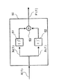
図1は、本発明の装置の基本的機能を示すためのブロック図である。該装置の一実施例が図2及び図3に一層詳しく示されている。マイクロホン1から到来する音声信号はA/D変換器2でサンプリングされてデジタル信号x(n)となる。
【0015】
音声コーデックにより使用されるフレーム長の均等商(even quotient)に対応する量の各サンプルがデジタル信号x(n)から取り出されて窓掛けブロック(windowing block)10に送られる。窓掛けブロック10において、フレームを形成するために、各サンプルに所定の窓(window)が乗算される。ブロック10において、フレームの長さをフーリエ変換に適するように調整するために、もし必要ならば窓掛けされたフレームに各サンプルが加算される。窓掛け後に、FFTブロック20において該フレームについて高速フーリエ変換(FFT)を使用してスペクトルが計算される。
【0016】
FFT計算20の後に、信号中の雑音を抑圧するために計算ブロック200で雑音抑制のための計算が行われる。雑音抑制のための計算を実行するために、FFTブロック20から得られたスペクトル成分X(f)に基づいて例えば振幅又はパワースペクトルP(f)などの所望のタイプのスペクトルがスペクトル形成ブロック50で形成される。各スペクトル成分P(f)は周波数領域において或る周波数範囲を表す、即ちスペクトルを利用して、処理される信号が異なる周波数の幾つかの信号即ちスペクトル成分P(f)に分割される。計算量を少なくするために、隣り合うスペクトル成分P(f)同士が計算ブロック60で合計され、スペクトル成分P(f)の数より少数の、或る数のスペクトル成分結合が得られて、前記スペクトル成分結合が抑圧係数を計算するために計算スペクトル成分S(s)として使われる。計算スペクトル成分S(s)に基づいて、推定ブロック190において信号が音声又は暗騒音を含んでいるか否かが検出され、暗騒音についてのモデルが形成され、計算スペクトル成分の各周波数範囲について信号対雑音比が形成される。この様にして得られた信号対雑音比と暗騒音モデルとに基づいて、各計算スペクトル成分S(s)について計算ブロック130で抑圧値G(s)が計算される。
【0017】
雑音を抑圧するために、掛け算器30において、スペクトル成分X(f)がその中に位置する周波数範囲に対応する抑圧係数G(s)が、FFTブロック20から得られた各スペクトル成分X(f)に乗じられる。IFFTブロック40において、雑音抑圧係数G(s)で調整された各スペクトル成分に対して逆高速フーリエ変換IFFTが実行され、ここから、窓掛けブロック10のために選択された各サンプルに対応する各サンプルが選択されて出力されて、出力即ち雑音抑圧されたデジタル信号y(n)となり、この信号は移動局において音声コーデックに回送されて音声符号化される。デジタル信号y(n)の各サンプルの量は、音声コーデックが使用するフレーム長の均等商であるので、音声コーデックのフレーム長に対応するような信号フレームが得られるまで、連続する雑音抑圧された信号y(n)が必要な量だけ音声コーデックに集められ、その後に音声コーデックは該音声フレームに対して音声符号化を実行することができるようになる。雑音抑圧器に使用されるフレーム長は音声コーデックのフレーム長の均等商であるので、この様にして雑音抑圧音声フレームと音声コーデック音声フレームとの長さが異なることに起因する遅延が防止される。
【0018】
計算スペクトル成分S(s)の数はスペクトル成分P(f)の数より少ないので、それらに基づいて抑圧成分を計算することは、パワースペクトル成分P(f)を計算に用いる場合よりかなり容易である。より広い周波数範囲について各々の新しい計算スペクトル成分S(s)が計算されているので、それらの変化はスペクトル成分P(f)の変化より小さい。それらの変化の原因は特に信号中のランダム雑音である。計算に使用される成分S(s)のランダムな変化が小さいので、連続するフレーム同士の間で計算される抑圧係数G(s)の変化も小さい。上記のように、周波数応答X(f)の数個のサンプルを乗じるために同じ抑圧係数G(s)が使用される結果として、同じフレーム内での周波数領域の変化が小さくなる。その結果として、抑圧係数の急激すぎる変化は不快に聞こえるので、音声の質が向上する。
【0019】
次に、主として図2及び図3を参照して本発明の一実施例を更に詳しく説明する。以下の記述に現れるパラメータの値は例示的な値であって、本発明の一実施例を描写するものであるけれども、それらは本発明の方法の機能を特定のパラメータ値のみに限定するものではない。この実施例では、FFT計算の長さは128サンプルであり、音声コーデックが使用するフレーム長は160サンプルであり、各音声フレームは20msの音声から成ると仮定されている。また、この実施例では、各スペクトル成分の数を65から8まで減らす、スペクトル成分の再結合が提示される。
【0020】
図2及び図3は本発明の装置の一実施例のより詳しいブロック図である。図2及び図3において、該装置への入力はA/D変換されたマイクロホン信号であるが、このことは、音声信号がサンプリングされて80個のサンプルから成るデジタル音声フレームとなっていることを意味する。音声フレームは窓掛けブロック10に入力され、ここで音声フレームに窓が乗算させられる。この実施例で使用される窓掛け(windowing)では窓同士が部分的に重なり合うので、部分的に重なり合う各サンプルが次のフレームのためにメモリ(ブロック15)に記憶される。80個のサンプルが信号から取り出されて、前のフレームの際に記憶された16個のサンプルと結合されて、合計で96サンプルとなる。最後に収集された各80個のサンプルの中から、最後の16個のサンプルが次のフレームの計算のために記憶される。
【0021】
この様にして、与えられた96個のサンプルに96個のサンプル値から成る窓が窓掛けブロック10において乗算され、図11に描かれているようにその窓の始めの8個の値は窓の立ち上がり部IU を形成し、最後の8個の値は窓の立ち下がり部ID を形成する。窓I(n)を下記のように定義することができ、ブロック11(図4)で実現される:
【数1】

窓掛け(ブロック11)をデジタル的に実施する方法はデジタル信号処理技術から当業者に知られている。この窓で中間の80個の値(n = 8,..,87 即ち中間部IM )は1であり、従ってそれらを乗算しても結果は変わらないので掛け算は省略される。従って、窓の中の始めの8個のサンプルと終わりの8個のサンプルだけを掛ければよい。FFTの長さは2の累乗でなければならないので、ブロック11から得られた96個のサンプルの終端部に32個のゼロ(0)がブロック12(図4)において付加されて、128個のサンプルから成る音声フレームとなる。サンプル列の終端部にサンプルを付加することは単純な操作であって、ブロック12をデジタル的に実現することは当業者にとっては従来公知のことである。
【0023】
窓掛けブロック10で実行される窓掛けの後に、ブロック20において音声フレームのスペクトルが高速フーリエ変換FFTにより計算される。FFTから得られた実数成分及び虚数成分は平方ブロック50で絶対値平方され、対をなして加え合わされ、その出力は音声フレームのパワースペクトルである。FFTの長さが128であるならば、得られるパワースペクトル成分の数は65であり、これはFFT変換の長さを2で割って、その結果を1だけ増やす(インクリメントする)ことにより得られる。即ちFFT/2+1の長さである。
【0024】
FFTブロック20に到着したフレームの中の各サンプルx(0),x(1),..,x(n);n=127(即ち前記の128個のサンプル)は実数(real)FFT(高速フーリエ変換)により周波数領域に変換されて周波数領域サンプルX(0),X(1),..,X(f);f=64(より一般的にはf=(n+1)/2)となり、その各サンプルは実数成分Xr(f)と虚数成分Xi(f)とから成る:
【数2】
高速フーリエ変換をデジタル的に実現することは当業者にとっては従来公知のことである。パワースペクトルは、実数成分及び虚数成分の2乗の和を成分毎に計算することにより平方ブロック(squaring block)50から得られる:
【数3】
図5に示されているように、実数成分及び虚数成分を平方ブロック(squaring blocks)51及び52(これらのブロックは従来公知の単純な2乗の計算をデジタル的に実行する)に入力し、その2乗された成分同士を総和器53で加え合わせることによって、平方ブロック50の機能を実現することができる。この様にして、平方ブロック50の出力として、パワースペクトル成分P(0),P(1),..,P(f);f=64が得られ、これらのパワースペクトル成分は次のように時間領域信号の種々の周波数の成分のパワーに対応する(8kHzのサンプリング周波数を使用すると仮定する):
f=0,...,64の値についてのP(f)は中間周波数(f・4000/64Hz)に対応する。 (4)
【0027】
8個の新しいパワースペクトル成分、すなわちパワースペクトル成分結合(すなわち一群の合成信号に相当する)S(s),s=0,..,7がブロック60で形成され、本書ではそれらを計算スペクトル成分と称する。この計算スペクトル成分(すなわち上記の合成信号)S(s)は、次の〔数4〕の通りに各計算スペクトル成分S(s)について常に7個の隣り合うパワースペクトル成分P(f)を合計することにより形成される:
【数4】
図6に示されているように、カウンタ61が常に7まで数え上げ、該カウンタにより制御されて総和器62が常に7個の連続する成分を合計してその総和を出力として発生するようにカウンタ61と総和器62とを利用することにより、これを実現することができる。この場合、最低位の結合成分S(0)は中間周波数 [62.5Hz〜437.5Hz] に対応し、最高位の結合成分S(7)は中間周波数 [3125Hz〜3500Hz] に対応する。これより低い(62.5Hzより低い)周波数と、これより高い(3500Hzより高い)周波数とは音声については重要でないので、電話システムでは常に減衰させられ、従って、それらを抑圧係数の計算に使うことは必要でない。
【0029】
他の種類の周波数範囲分割方法を用いてパワースペクトル成分P(f)から計算スペクトル成分S(s)を形成することもできる。例えば、結合されて1つの計算スペクトル成分S(s)とされるパワースペクトル成分P(f)の個数は、異なる計算スペクトル成分又は異なるsの値に対応する異なる周波数帯域について異なっていてもよい。更に、異なる数、即ち8より大きい数や小さい数、の計算スペクトル成分S(s)を使用することもできる。
【0030】
隣り合う成分同士を加え合わせるという方法以外にも、各成分を再結合させる方法が幾つもあることに注意しなければならない。一般に、次のように適当な係数でパワースペクトル成分P(f)に重みを付けることによって前記計算スペクトル成分S(s)を計算することができる:
【数5】
【0031】
上記したように、スペクトル成分、即ち周波数範囲、の質は数個の範囲の成分を合計することによってかなり低下している。計算スペクトル成分を形成した後の、次の段階は、抑圧係数の計算である。
【0032】
抑圧係数を計算するとき、前記の計算スペクトル成分S(s)が使われ、それらに対応する抑圧係数G(s),s=0,・・・,7が計算ブロック130で計算される。周波数領域サンプルX(0),X(1),...,X(f);f=0,..,64に前記の抑圧係数が乗算される。各係数G(s)は、各成分S(s)を計算する基礎として使われた各サンプルに乗算される、例えば各サンプルX(15),..,X(21)にG(2)が乗算される。また、最下位のサンプルX(0)にはサンプルX(1)と同じ係数が乗算され、最高位の各サンプルX(57),..,X(64)にはサンプルX(56)と同じ係数が乗算される。
【0033】
乗算は掛け算器30で実数成分と虚数成分とを別々に掛け合わせることにより実行され、その出力として下記の結果が得られる:
【数6】
この様にしてY(f);f=0,..,64が得られ、その実逆高速フーリエ変換(real inverse fast Fourier transform)がIFFTブロック40で計算され、その出力として時間領域サンプルy(n),n=0,..,127が得られるが、その中の雑音は抑圧されている。
【0035】
より一般的には、各周波数領域サンプルX(0),X(1),..,X(f),f=0,..,64についての抑圧を、次のようにして数個の抑圧係数の重み付き総和として計算することができる:
【数7】
【0036】
計算スペクトル成分S(s)は8個しかないので、それらに基づく抑圧係数の計算は、65個のパワースペクトル成分P(f)を用いて計算を行う場合よりは相当容易である。各々の新しい計算スペクトル成分S(s)はより広い範囲について計算されているので、それらの値の変化は各パワースペクトル成分P(f)の変化より小さい。これらの変化は特に信号中のランダム雑音に起因するものである。計算に用いられる計算スペクトル成分S(s)のランダムな変化が小さいので、連続するフレーム同士の間での計算された各抑圧係数G(s)の変化も小さい。同じ抑圧係数G(s)が、上記の通りに、周波数応答X(f)の幾つかのサンプルに乗算されるので、フレーム内の周波数領域の変化が小さくなる。抑圧係数の急激すぎる変化は不快に聞こえるので、その結果として音声の質が向上する。
【0037】
計算ブロック90において、次に説明するように、関係するフレームのパワースペクトル成分と、暗騒音モデルの対応する成分との比として各周波数帯域で後天的(posteriori)信号対雑音比が計算される。
【0038】
音声活性検出器(voice activity detector)が音声を検出しないとき、雑音のスペクトルN(s),s=0,..,7が推定ブロック80で推定される(図10により詳しく示されている)。ブロック80において、ブロック60から得られた信号のスペクトルの各成分S(s),s=0,..,7について時間平均された平均値を巡回的に(recursively)計算することにより、推定が行われる:
【数8】
この文脈において、Nn-1 (s) は、図10に示されているように、メモリ83から得られる、前のフレームについて計算された雑音スペクトル推定値を意味し、Nn (s) は上記の等式による現在のフレーム(n=フレームの順序番号)についての推定値を意味する。この計算はブロック81で好ましくはデジタル的に実行される。ブロック81の入力は、ブロック60からの各スペクトル成分S(s)と、メモリ83から得られる前のフレームについての推定値Nn-1 (s) と、ブロック82で計算される変数λの値とである。変数λは、Vind ’(音声活性検出器の出力)の値とSTcount (暗騒音スペクトル推定値の更新の制御に関連する変数)の値とに依存し、その計算については後述する。変数λの値は、下記の表3のテーブル(λについての代表的な値)に従って決定される:
【表3】
後に、現在のフレームについて計算された雑音スペクトル推定値について、より短い記号N(s)が用いられる。上記の推定方法による計算はデジタル的に実行されるのが好ましい。上記の式に従って掛け算、足し算及び引き算をデジタル的に実行する方法は当業者にとっては従来公知のことである。
【0041】
計算ブロック90において、入力スペクトル及び雑音スペクトルから、比γ(s),s=0,..,7が成分毎に計算され、この比は後天的信号対雑音比と呼ばれる:
【数9】
【表4】
【数10】
【数11】
【数12】
【0043】
この修正推定値(ホ)を計算するときには、本発明に従って相対雑音レベル(relative noise level)を使用する。このことについて次に説明をする。
【0044】
本発明の方法では、雑音抑圧の調節は、相対雑音レベルη(その計算については後述する)に基づいて、現在のフレームから計算されるパラメータを追加的に使用して制御され、このパラメータは入力信号と雑音モデルとの間のスペクトル距離DSNR を表し、この距離の計算方法については後述する。このパラメータは、相対雑音レベルを表すパラメータを、そしてそれを通じて先天的信号対雑音比(ヘ)の値をスケーリング(scaling)するために使われる。スペクトル距離パラメータの値は、現在のフレームにおける音声の出現確率を表す。従って、フレームに暗騒音だけがきれいに含まれているほど、先天的信号対雑音比(ヘ)の値の増加量は少なくされ、これにより実際上より効果的な雑音抑圧を行えるようになる。フレームが音声を含んでいるときには抑圧量は少なくされるが、音声が周波数領域及び時間領域の両方で効果的に雑音をマスクする。抑圧量の調節のために使われるスペクトル距離パラメータの値は連続的な値を持っていて、信号のパワーの変化に即座に反応するので、不快に聞こえる抑圧量調節の中断は生じない。
【0045】
音声と比べて雑音が大きくなるほど、雑音抑圧により一層大きな歪みが音声に生じるというのが従来公知の雑音抑圧方法の特徴である。本発明では、操作が改善されていて、音声のパワー及び雑音のパワーから、滑らかに移行する平均値(ト)及び(チ)が巡回的に(recursively)計算される。それらに基づいて、相対雑音レベルを表すパラメータηが計算され、雑音抑圧G(s)がそれにより調整される。
【0046】
前記の平均値及びパラメータはブロック70で計算される。このブロックのより詳細な構成が図7に示されており、これについて次に説明する。抑圧量の調節は、相対雑音レベルηに基づいて先天的信号対雑音比(ヘ)の値を大きくすることにより実行される。これにより、顕著な歪みが音声に生じないように雑音抑圧量を相対雑音レベルηに従って調節することができる。
【0047】
音声の過渡的変化に対する良好な応答を確保するために、等式(11)の抑圧係数G(s)は音声の活性に対して速やかに反応しなければならない。残念なことに、音声の過渡的変化に対する抑圧係数の感度が高くなると、不安定な雑音に対する抑圧係数の感度も高くなり、残留雑音の響きは元の雑音より滑らかでなくなる。更に、等式(7)の暗騒音スペクトルN(s)の形及びレベルの推定は算術平均により巡回的に実行されるので、推定アルゴリズムは、急速に変化する雑音成分を模するのに充分な速さで順応することができなくて、その様な雑音成分の減衰の効率が悪くなる。実際、減衰させられた変化しない雑音によるその様な急速に変化する雑音成分のマスキング効果が低下しているために、強化後にはその様な成分がもっとはっきりと区別できるようになることがある。
【0048】
スペクトル成分の数を増やすことにより抑圧係数の計算のスペクトル分解能を高めたときにも、残留雑音の望ましくない変化が生じる。この様な滑らかさの低下は、周波数領域でのパワースペクトル成分の平均化が弱まった結果である。しかし、音声活性時の適切な減衰と、音声に生じる歪みの極小化とのために、充分な分解能が必要である。
【0049】
周波数範囲の分割が最適でない場合には、雑音が低周波数に高度に集中していると、抑圧作用において低周波数暗騒音に望ましくない変動が生じることがある。音声に低周波数の雑音が大量に含まれているために、音声を含むフレームにおいて同じ低周波数領域の雑音の減衰が弱まり、不快に聞こえる変調が残留雑音に対して音声のリズムでかけられる結果となる。
【0050】
上記した3つの問題を、最小利得探索により効率よく軽減することができる。この方式の原理は、各周波数成分において信号のパワーは雑音よりも音声においてゆっくりと且つ比較的に軽い不規則性をもって変化するという事実に導かれている。この方式により、暗騒音抑圧の結果が滑らかになり且つ安定し、音声音の劣化の程度が軽くなり、残留暗騒音がより滑らかになり、強化された音声の主観的な質が向上する。特に、音声及び雑音の双方がある時にこの方法により、あらゆる種類の急速に変化する不安定な暗騒音成分を効率よく減衰させることができる。更に、この方法は音声に如何なる歪みも生じさせず、余計な雑音を減らして音声をきれいに響かせる。更に、最小利得探索法(minimum gain search)によれば、残留雑音に余分の変動を生じさせることなく等式(11)での抑圧係数G(s)の計算における周波数成分の数を増やすようにすることができる。
【0051】
最小利得探索法では、現在のフレームと、現在のフレームが音声音を含んでいるか否かにより例えば1個又は2個の前のフレームとから、各周波数成分sでの等式(24)の抑圧係数G’(s)の最小値を探索する。最小利得探索方式は、下記の様に表現できるものである:
【数13】
【0052】
抑圧係数G’(s)は、ブロック30(図3の)での複素FFT(complex FFT)の該抑圧係数との乗算の前に等式(12)に従って最小利得探索法により修正される。最小利得法(minimum gain)は、ブロック130で、又はブロック130と120との間に挿入される別のブロックで実行されることができる。
【0053】
その中から抑圧係数の最小値を探し出す前のフレームの個数は2より多くてもよい。更に、最小値を取る方法以外の、抑圧係数についての他の種類の非線形フィルタリング操作(例えば、中央値、最小値と中央値との何らかの組み合わせ、など)又は線形フィルタリング操作(例えば、平均)を本発明で用いることもできる。
【0054】
上記した方式の算術的複雑さは低い。雑音抑圧に抑圧係数の下限を導入することにより最大減衰量を限定しており、また抑圧係数は振幅領域に関連するものであって累乗変数(power variable)ではなく、従って程良いダイナミックレンジを保有するので、これらの係数を効率よく圧縮することができる。前の数個のフレームの抑圧係数を記憶させなければならないけれども、静的メモリの消費量は少ない。雑音抑圧結果を滑らかにする上記の方法のメモリ要件は、例えば以前の幾つかの方式で提案されている、同じ目的のために過去のフレームの高分解能パワースペクトルを利用する方法と比べて、有利である。
【0055】
【表5】
【数14】
時間平均された平均値(リ)は、前のフレームの時に計算された時間平均された平均値が記憶されているメモリ78から得られる前のフレームについての時間平均された平均値(ル)と、ブロック71から得られる計算スペクトル平均値(ヌ)と、前もってメモリ79aに記憶されている時定数αとに基づいて、ブロック72において(例えば巡回的に)計算される:
【数15】
【0057】
同様に、雑音のパワーの時間平均された平均値(オ)は雑音N(s),s=0,..,7のパワースペクトル推定値を用いて計算ブロック73から得られ、成分平均値(ワ)はそれから次の等式に従って計算される:
【数16】
ここでβは時定数であって、その値は0.0〜1.0であり、通常は0.9と1.0との間である。雑音パワーの時間平均された平均値は各フレームで更新される。雑音スペクトル成分の平均値(ワ)は、スペクトル成分N(s)に基づいてブロック76で次のように計算される:
【数17】
【0059】
相対雑音レベルηは、ブロック75において、雑音及び音声の時間平均された平均値のスケーリングされ且つ最大値限定された商として計算される:
【数18】
【0060】
相対雑音レベルηについてのこのパラメータから、抑圧量調整に使われる最終補正項が、入力信号と雑音モデルとの間の距離を表すパラメータDSNR でそれをスケーリングすることによって得られ、このDSNR は、後天的信号対雑音比γ(s)を用いて音声活性検出器110で計算され、これはデジタル的計算により次の式を実現する:
【数19】
【0061】
次に、図12を参照して音声活性検出器110の実施例について詳しく説明する。音声活性検出器の実施例は新しいものであって、本発明の雑音抑圧器に用いるのに特に適しているけれども、この音声活性検出器を、例えば断続的な接続を制御するため及び音響エコー消去のために音声検出を行う他の種類の雑音抑圧器に、或いは他の目的のために、用いることも可能である。音声活性検出器における音声の検出は、信号対雑音比に、又は図2及び図3から分かるようにブロック90で計算された種々の周波数帯域での後天的信号対雑音比に基づいている。この信号対雑音比は、フレームについてのパワースペクトル成分S(s)(ブロック60からの)を、暗騒音推定値の対応する成分N(s)(ブロック80からの)で割ることにより、計算される。音声活性検出器の中の総和器111は、種々の周波数帯域から得られる後天的信号対雑音比の値を合計し、これにより、入力信号と雑音モデルとの間のスペクトル距離を表すパラメータDSNR が上記の式(18)に従って得られ、この総和器からの値は比較器112において所定の閾値vthと比較される。もし閾値の方が小さければ、そのフレームは音声を含むと見なされる。この合計を計算するとき、信号対雑音比が良好であると期待することのできる周波数に、より大きな重みを付けるように、重み付けを行うこともできる。音声活性検出器の出力を変数Vind ’で表すことができるが、その値について下記の条件が得られる:
【数20】
音声活性検出器110は暗騒音スペクトル推定値N(s)の更新を制御し、この推定値は上記したように音声活性検出器の機能に影響を及ぼすので、もし暗騒音レベルが急に上昇すると暗騒音スペクトル推定値N(s)が低すぎるレベルにとどまる可能性がある。これを防止するために、その中では連続するフレームが音声を含んでいると考えられる時間(フレームの個数)が監視される。もしこの連続するフレームの個数が閾値max_spf(その値は例えば50である)を上回れば、変数STcount の値は1にセットされる。変数STcount は、Vind ’が値0となったときに0にリセットされる。
【0063】
しかし、連続するフレームのエネルギーの変化が信号が安定していないことをブロック80に示すならば、連続するフレームのためのカウンタ(この図には示されていないけれども図10にはブロック82として含まれており、ここに変数STcount の値も記憶される)の値は増やされない。定常度を表すパラメータSTind がブロック100で計算される。もしエネルギーの変化が充分に大きければ、該カウンタはリセットされる。これらのことの目的は、音声時に暗騒音スペクトル推定値が更新されないことを保証することである。また、当該フレームのパワースペクトル成分が暗騒音スペクトル推定値N(s)の対応する成分より小さいときには常に各周波数帯域で暗騒音スペクトル推定値N(s)が小さくされる。これにより、誤った更新がなされた後に暗騒音スペクトル推定値N(s)が確実に急速に正しいレベルに戻ることになる。
【0064】
定常度についての条件を、後記の式(27)で見ることができる。項目a)は信号が安定した状況に対応し、このときは連続する音声フレームのカウンタの値が増やされる。項目b)は非安定状態に対応し、このときは該カウンタはリセットされ、項目c)は該カウンタの値が変えられない状態に対応する。
【0065】
また、本発明では、相対雑音レベルη(これはブロック70で計算される)を利用して音声活性検出器の前記の閾値vthを調整することにより、音声活性検出器110及び暗騒音スペクトル推定値N(s)の精度が高められる。信号対雑音比が非常に良好である(即ち相対雑音レベルηが低い)様な環境では、閾値vthの値は相対雑音レベルηに基づいて高められる。これにより暗騒音の急速な変化を音声と解釈することが少なくなる。閾値の適応化は、次の式に従ってブロック113で実行される:
【数21】
【0066】
【表6】
【0067】
音声バースト後でも、音声活性検出器が雑音だけを検出してもN個のフレーム(例えばN=1)(このときは「ホールド時間」と呼ばれる)の間の音声を意味する決定を音声活性検出器から強制的に出させるようにして音声活性検出器110を強化することもできる。これにより、音声がゆっくりと静かになりつつあるときに音声の終わりが雑音と解されることがあり得るので、作用が向上する。
【0068】
前記ホールド時間を相対雑音レベルηに適応的に依存させることができる。その場合、暗騒音が強いとき、静かなときと比べてホールド時間はゆっくりと長くされる。このホールド作用を次のように実現することができる。即ち、ホールド時間nに値0,1,..,Nが与えられ、相対雑音レベルの閾値η0 ,η1 ,....,ηN-1 ;ηK <ηK+1 ,が計算され、その値はホールド時間に対応すると見なされ得るものである。実時間でホールド時間は相対雑音レベルの瞬時値を閾値と比較することにより選択される。例えば、次の通りである(N=1,η0 =0.01):
【数22】
このホールド時間を含むVAD決定はVind で表される。
【0070】
ホールド作用を、図12に示されているように音声活性検出器の出力側に置かれる遅延ブロック114を用いて好ましく実現することができる。特許US4,811,404は、暗騒音スペクトル推定値を更新する方法を開示しており、この方法では、暗騒音スペクトル推定値の前回の更新の時から一定の時間が経過すると自動的に新たに更新が行われる。本発明では暗騒音スペクトル推定値の更新は、一定の間隔では行わず、上記したように音声活性検出器の検出結果に応じて行う。暗騒音スペクトル推定値が計算された後、音声活性検出器が現在のフレームの前にも後にも音声を検出していないときに限って暗騒音スペクトル推定値の更新が行われる。この処理手順により、可能な限り正しい値を暗騒音スペクトル推定値に与えることができる。特にこの特徴と、前記の他の特徴(例えば、音声があるか無いかを判定する基礎となる閾値の値vthを、音声及び雑音の両方のレベルを考慮に入れた相対雑音レベルに基づいて調節するという特徴など)は、暗騒音スペクトル推定値の精度と音声活性検出器の動作との双方を本質的に向上させる。
【0071】
次に、抑圧係数G’(s)の計算方法を図8を参照して説明する。相対雑音レベルについてのパラメータηにスペクトル距離についてのパラメータDSNR を乗じ、その積をメモリ132に記憶されているスケーリング定数(scalingconstant)ρでスケーリングし、その積の最大値を制限することによって、抑圧係数の計算を制御するための補正項φがブロック131から得られる:
【数23】
【0072】
抑圧係数(ソ)(s=0,...,7)の計算の調整は次のようにして行われる。即ち、式(9)に従って計算ブロック140から得られる先天的信号対雑音比(ツ)の値を、先ずブロック131で計算された補正項φを使って、ブロック133での計算により次のように変換する:
【数24】
【0073】
信号が最早音声を含んでいないことを音声活性検出器110が検出すると、適当な時定数を用いて信号が更に抑圧される。音声活性検出器110は、音声表示出力Vind ’を出すことによって、信号が音声を含んでいるか否かを示し、この出力は例えば1ビットであり、その値は、もし音声がなければ0であり、信号が音声を含んでいるならば1である。追加の抑圧は、動き検出器(mobility detector)、すなわち安定度指示手段100で計算される信号安定度指示子STind に基づいて更に調整される。この方法により、音声活性検出器110が暗騒音と解釈する可能性のある静かな音声シーケンスを抑圧することが防止される。
【0074】
追加の抑圧は、抑圧係数G’(s)を計算する計算ブロック138で実行される。音声の開始時に、適当な時定数を用いて追加の抑圧が解除される。音声活性検出器110により、音声活性の終了後に、音声を含まない或る数(その数は予め決められた定数(ハングオーバー期間(hangover period) である)のフレームが検出されたときに、追加の抑圧が開始される。関係期間(ハングオーバー期間)に含まれるフレームの数は分かっているので、フレームの数を数えるカウンタCTを用いてその期間の終了を検出することができる。
【0075】
追加の抑圧を含む抑圧係数G’(s)は、前もってブロック134で計算された抑圧値(ソ)とブロック137で計算される追加の抑圧係数σとに基づいてブロック138で次の式に従って計算される:
【数25】
【数26】
【数27】
【数28】
定数th_s及びth_nは1より大きい。代表的な値は、例えば、th_s=6.0/5.0で、th_n=2.0、又は例えばth_s=3.0/2.0で、th_n=8.0である。各差項δs、δn及びδmの値は、たとえ安定度指示子STind の値が非常に頻繁に変化しても連続するフレーム間での追加の抑圧量の差が騒がしく聞こえることのない様に、選択される。
【数29】
音声活性検出器110が音声を再び検出すると、追加の抑圧は、追加の抑圧係数σをブロック137で次の様に計算することにより除去される:
【数30】
【0078】
抑圧値計算ブロック130から得られた8個の抑圧値G(s)は、処理される周波数範囲の外側の周波数(0−62.5Hz及び3500Hz−4000Hz)に対応する抑圧値が、隣接する処理される周波数帯域についての抑圧値に等しくセットされることとなるように、補間器120において補間されて65個のサンプルとされる。補間器120もデジタル的に実現されるのが好ましい。
【0079】
掛け算器30において、FFTブロック20により作られた対をなす実数成分Xr (f)及び虚数部分Xi (f)に補間器120から得られた抑圧値が乗算され、ここでFFTブロックからの8個の連続するサンプルX(f)に実際上常に同じ抑圧値G(s)が乗算され、前記の式(6)に従って各サンプルが掛け算器30の出力として得られる。
【0080】
ここで各サンプルY(f),f=0,..,64が得られ、これから実逆高速フーリエ変換がIFFTブロック40で計算され、ここでその出力として時間領域サンプルy(n),n=0,..,127が得られ、このサンプルでは雑音が抑圧されている。雑音が既に抑圧されている各サンプルy(n)は、FFTブロックに入力される各サンプルx(n)に対応する。
【0081】
それらのサンプルy(n)の中から80個のサンプルが選択ブロック160で選択されて送信されるべく出力される。それらのサンプルはy(n);n=8,..,87であり、それらに対応するx(n)の値には窓のストリップが乗算されていないので、それらを直接出力側に送ることができる。この場合、出力側に80個のサンプルが得られるが、それらのサンプルは、窓掛けブロック10に入力信号として読み込まれる各サンプルに対応するサンプルである。ここで説明した実施例では各サンプルは8番目のサンプルから出力側へ選択されるけれども、現在のフレームに対応する各サンプルは16番目のサンプルからはじめて始まるので(始めの16個は前のフレームからメモリに記憶されたサンプルである)、信号に8サンプルの遅延即ち1msの遅延が生じる。もし最初に、もっと多数の(例えば112個の)サンプルを読み出していれば(112+前のフレームの16サンプル=128)、0を信号に付け加える必要はなく、その結果として前記の112個のサンプルが直接出力側から得られることになる。しかし、今は一度に80個のサンプルを出力側から得たいので、2個の連続するフレームに対する計算の後に160個のサンプルが得られ、これは現在(例えばGSM移動電話などで)使用されている殆どの音声コーデックが利用しているサンプルに等しい。これにより、上記の1msを除いて、如何なる遅延も生じさせることなく雑音抑圧と音声符号化とを効果的に組み合わせることができる。比較のために、次の様に言うことができる、即ち、現在の技術水準では遅延は通常は窓(window)の長さの半分であり、従って本書に開示した例示的解決策による窓(window)を使用するときは(この窓の長さは96フレームである)、遅延は48サンプル即ち6msとなり、この遅延は本発明の解決策で達成される遅延の6倍の長さである。
【0082】
雑音抑圧のための本発明の方法と装置とは移動局又は移動通信システムに用いるのに特に適していて、特別のアーキテクチャ(TDMA、CDMA、デジタル/アナログ)に限定されるものではない。図13は本発明の移動局を示し、これに本発明の雑音抑圧方法が使用されている。マイクロホン1から到来する、送信されるべき音声信号は、A/D変換器2でサンプリングされ、本発明の雑音抑圧器3で雑音抑圧され、音声符号器4で音声符号化され、その後に、例えばチャネル符号化、インタリーブなどの従来公知の基本周波数信号処理がブロック5で実行される。この後、信号は無線周波数に変換され、送信器6により複式フィルターDPLX及びアンテナANTを通して送信される。受信された音声に対して受信部7の公知の動作が受信時に実行され、スピーカー8を通して再生される。
【0083】
本発明の方法及び装置の実施態様及び実施例をここに開示した。本発明は、ここに開示した実施例の細目に限定されるものではなく、本発明の特徴から逸脱せずに他の形でも本発明を実施し得ることは当業者には明かである。ここに開示した実施例は単なる例に過ぎないと見なされるべきであり、発明を限定するものと解されるべきではない。従って、本発明を実施し利用する可能性は、特許請求の範囲に規定された種々の請求項のみにより限定される。該請求項で規定される発明を実施するための、均等実施態様を含む種々の選択肢が本発明の範囲に含まれる。
【図面の簡単な説明】
【図1】音声信号中の雑音を抑圧するための本発明の装置の基本的機能に関するブロック図である。
【図2】本発明による雑音抑圧器(noise suppressor)の一層詳しいブロック図(その1)である。
【図3】本発明による雑音抑圧器の一層詳しいブロック図(その2)である。
【図4】窓掛けブロック(windowing block)の実施態様をブロック図の形で示す図である。
【図5】平方ブロック(squaring block)の実施態様を示す図である。
【図6】スペクトル再結合ブロック(spectral recombination block)の実施態様を示す図である。
【図7】相対雑音レベル(relative noise level)を計算するためのブロックの実施態様を示す図である。
【図8】抑圧係数(suppression coefficients)を計算するためのブロックの実施態様を示す図である。
【図9】信号対雑音比を計算するための構成を示す図である。
【図10】暗騒音モデル(background noise model)を計算するための構成を示す図である。
【図11】本発明による窓掛け(windowing)における連続する音声信号フレームを示す図である。
【図12】音声活性検出器(voice activity detector)の実施態様をブロック図の形で示す図である。
【図13】本発明による移動局をブロック図の形で示す図である。
【符号の説明】
1…マイクロホン
10…窓掛けブロック
20…FFTブロック
30…掛け算器
40…IFFTブロック
50…スペクトル形成ブロック
60…計算ブロック
130…計算ブロック
190…推定ブロック
200…計算ブロック
G(s)…抑圧係数[0001]
BACKGROUND OF THE INVENTION
The present invention relates to a noise suppression method, a mobile station, and a noise suppressor for suppressing noise in a voice signal. The suppressor includes means for dividing the audio signal into a first amount of sub-signals representing a predetermined first frequency range, and suppression means for suppressing noise in the sub-signals according to a predetermined suppression coefficient. Have The noise suppressor of the present invention can be used for canceling acoustic background noise particularly in a mobile station operating in a cellular communication network. The present invention particularly relates to background noise suppression based on spectral subtraction.
[0002]
[Prior art]
Various noise suppression methods based on spectral subtraction are known from the prior art. Algorithms using spectral subtraction are generally used by using a fast Fourier transform (FFT) as disclosed in patent publications WO 89/06877 and US 5,012,519, or patent publications US 4,630,305, US4. 630, 304, US4, 628, 529, US4, 811, 404 and EP343792, by using filters, the signal is divided into frequency components according to frequency, ie in a smaller frequency range. Based on splitting. In the conventional method based on spectral subtraction, components corresponding to each frequency range of the power spectrum (amplitude spectrum) are calculated, and each frequency range is processed separately, that is, noise is suppressed separately for each frequency range. Normally, such processing is performed as follows. That is, whether each frequency range signal includes sound is detected separately for each frequency range, and if it does not, noise is involved, the signal is suppressed. Finally, by recombining the signals in each frequency range, the output is a noise-suppressed signal. A disadvantage of the known method based on spectral subtraction is that it is computationally intensive because the calculation has to be performed separately for each frequency range.
[0003]
A noise suppression method based on spectral subtraction generally obtains an estimate of a noise signal and uses it to adjust the amount of noise attenuation in various frequency bands. It is known in the art to measure the amount of a variable representing the power of noise and adjust the gain using this. Patent US 4,630,305 discloses a noise suppression method that uses a table of suppression values for various ambient noise values and attempts to use the average noise level for attenuation adjustment. Is.
[0004]
In connection with spectral subtraction, windowing is known. The purpose of windowing is generally to improve the quality of the spectral estimate of the signal by dividing the signal into frames in the time domain. Another basic purpose of windowing is to subdivide a fluctuating (unstable) signal, such as speech, into segments (frames) that can be considered non-fluctuating (stable). is there. As for windowing, it is generally known to use a Hamming type, Hanning type, or Kaiser type windowing method. The method based on spectral subtraction uses the so-called 50% overlapping Hanning windowing method and the so-called overlap-add method used in conjunction with inverse FFT (IFFT). It is common.
[0005]
[Problems to be solved by the invention]
The problem with all of these previously known methods is that the windowing method has a specific frame length and it is difficult to match the length of the windowing frame with other frame lengths. For example, in a digital mobile telephone network, voice is encoded by frames and specific voice frames are used in the system, so each voice frame has the same specified length, eg 20 ms. When the frame length for windowing is different from the frame length for speech coding, it is caused by noise suppression and speech coding because each frame length used for noise suppression and speech coding is different The total amount of delay is a problem.
[0006]
[Means for Solving the Problems]
In the method of suppressing noise according to the present invention, an input signal is first divided into a first amount of frequency bands, a power spectrum component corresponding to each frequency band is calculated, and a second amount of power spectrum components is re-generated. By combining, a calculated spectral component representing a second frequency band wider than the first frequency band is obtained, and a suppression coefficient for the calculated spectral component is determined based on noise included in the calculated spectral component. The second amount of the power spectrum component is suppressed using a suppression coefficient based on the calculated spectral component. Preferably, several calculated spectral components representing several adjacent frequency bands are formed, each calculated spectral component being formed by recombining various power spectral components. Each calculated spectral component may consist of several power spectral components different from the others, or may consist of several power spectral components equal to the other calculated spectral components. In this way, a suppression coefficient for noise suppression is formed for each calculated spectral component, each calculated spectral component is attenuated, and the attenuated calculated spectral component is reconverted to the time domain, recombined, and noise suppressed. Output signal. Preferably, the calculated spectral components are less than the first amount of frequency band, and as a result, the amount of calculation is reduced without reducing voice quality.
[0007]
One embodiment of the present invention divides each frequency component based on the FFT transform. One advantage of the present invention is that the method of the present invention has the significant advantage that the number of frequency range components is reduced, resulting in less computation when calculating the suppression coefficient. When forming each suppression coefficient based on a wide frequency range, random noise cannot change the value of the suppression coefficient abruptly. Since sudden fluctuations in the value of the suppression coefficient sound unpleasant, an improvement in voice quality is achieved in this way.
[0008]
In the method of the present invention, each frame is formed by windowing from an input signal, and in the windowing, a frame having a length that is an even quotient of the frame length used for speech coding is used. . In this context, the equal quotient means a number that is evenly divisible by the frame length used for speech coding. For example, the equal quotient of the frame length 160 is 80, 40, 32, 20, 16, 8, 5, 4, 2, and 1 means. This type of approach significantly reduces the total amount of delay.
[0009]
Yet another difference between the aforementioned US Pat. No. 4,630,305 and the method of the present invention is to obtain the average voice power to determine the relative noise level. By determining the estimated speech level and the noise level and performing noise suppression using them, a better result can be obtained than when only the noise level is used. The reason is that the ratio between the speech level and the noise level is very important for the noise suppression algorithm.
[0010]
Furthermore, in the method of the present invention, the amount of suppression is adjusted according to a continuous noise level value (continuous relative noise level value), unlike the conventional method using a fixed value on the table. In the method of the present invention, as described in more detail later, the amount of suppression is reduced according to the relative noise estimate in accordance with the current signal-to-noise ratio in each band. For this reason, the voice is kept as natural as possible, and the voice can overwhelm the noise in a band where the voice is dominant. This continuous suppression adjustment is realized by using each variable having a continuous value. By using each parameter that is continuous, that is, not fixed on the table, it is possible to perform noise suppression without causing a large instantaneous change in the noise suppression value. In addition, a large storage capacity necessary for making a table of conventionally known gain values becomes unnecessary.
[0011]
The noise suppressor and the mobile station according to the present invention comprise recombining means for recombining a second amount of sub-signals into a calculated signal representing a predetermined second frequency range wider than the first frequency range. And a determination means for determining a suppression coefficient for the calculation signal based on noise included in the calculation signal, and the suppression means is recombined to form the calculation signal. The sub-signal is suppressed by the suppression coefficient determined based on the calculation signal.
[0012]
The noise suppression method of the present invention recombines the second amount of sub-signals before performing noise suppression to obtain a calculated signal representing a predetermined second frequency range wider than the first frequency range, A suppression coefficient for the calculation signal is determined based on noise included in the calculation signal, and the sub-signals that are recombined into the calculation signal are determined by the suppression coefficient determined based on the calculation signal. It is characterized by suppression.
[0013]
DETAILED DESCRIPTION OF THE INVENTION
Next, the noise suppression system of the present invention will be described in detail with reference to the accompanying drawings.
[0014]
FIG. 1 is a block diagram for showing the basic functions of the apparatus of the present invention. One embodiment of the device is shown in more detail in FIGS. The audio signal coming from the
[0015]
Each sample of an amount corresponding to the even quotient of the frame length used by the audio codec is extracted from the digital signal x (n) and sent to the
[0016]
After the
[0017]
In order to suppress the noise, in the
[0018]
Since the number of calculated spectral components S (s) is less than the number of spectral components P (f), calculating the suppression component based on them is much easier than using the power spectral component P (f) for the calculation. is there. Since each new calculated spectral component S (s) has been calculated for a wider frequency range, their change is smaller than the change of the spectral component P (f). The cause of these changes is in particular random noise in the signal. Since the random change of the component S (s) used for the calculation is small, the change of the suppression coefficient G (s) calculated between successive frames is also small. As described above, as a result of using the same suppression coefficient G (s) to multiply several samples of the frequency response X (f), changes in the frequency domain within the same frame are reduced. As a result, too rapid a change in the suppression coefficient sounds uncomfortable, thus improving voice quality.
[0019]
Next, an embodiment of the present invention will be described in more detail with reference mainly to FIGS. Although the parameter values appearing in the following description are exemplary values and depict one embodiment of the present invention, they do not limit the functionality of the method of the present invention to only certain parameter values. Absent. In this example, it is assumed that the length of the FFT calculation is 128 samples, the frame length used by the speech codec is 160 samples, and each speech frame consists of 20 ms speech. This embodiment also presents a recombination of spectral components that reduces the number of each spectral component from 65 to 8.
[0020]
2 and 3 are more detailed block diagrams of one embodiment of the apparatus of the present invention. 2 and 3, the input to the device is an A / D converted microphone signal, which means that the audio signal is sampled into a digital audio frame of 80 samples. means. The audio frame is input to the
[0021]
In this way, the given 96 samples are multiplied in the
[Expression 1]
Methods for digitally performing windowing (block 11) are known to those skilled in the art from digital signal processing techniques. The middle 80 values in this window (n = 8,. M ) Is 1, so multiplication is omitted because multiplication does not change the result. Therefore, only the first 8 samples and the last 8 samples in the window need to be multiplied. Since the length of the FFT must be a power of 2, 32 zeros (0) are appended in block 12 (FIG. 4) to the end of the 96 samples obtained from
[0023]
After the windowing performed in
[0024]
Each sample x (0), x (1),. . , X (n); n = 127 (i.e., the above 128 samples) are transformed into the frequency domain by a real FFT (Fast Fourier Transform), and frequency domain samples X (0), X (1),. . , X (f); f = 64 (more generally f = (n + 1) / 2), each sample comprising a real component Xr (f) and an imaginary component Xi (f):
[Expression 2]
It is well known to those skilled in the art to digitally implement the fast Fourier transform. The power spectrum is obtained from the squaring
[Equation 3]
As shown in FIG. 5, the real and imaginary components are input to squaring
f = 0,. . . , 64 corresponds to the intermediate frequency (f · 4000/64 Hz). (4)
[0027]
Eight new power spectral components, ie, power spectral component combinations (ie corresponding to a group of synthesized signals) S (s), s = 0,. . , 7 are formed at
[Expression 4]
As shown in FIG. 6, the
[0029]
The calculated spectral component S (s) can also be formed from the power spectral component P (f) using other types of frequency range dividing methods. For example, the number of power spectral components P (f) combined into one calculated spectral component S (s) may be different for different calculated spectral components or different frequency bands corresponding to different values of s. In addition, different numbers of calculated spectral components S (s) can be used, i.e. numbers greater or less than eight.
[0030]
It should be noted that there are several ways to recombine each component other than adding adjacent components together. In general, the calculated spectral component S (s) can be calculated by weighting the power spectral component P (f) with an appropriate factor as follows:
[Equation 5]
[0031]
As noted above, the quality of the spectral components, i.e. the frequency range, is significantly reduced by summing the components in several ranges. The next step after forming the calculated spectral components is the calculation of the suppression coefficient.
[0032]
When calculating the suppression coefficients, the calculated spectral components S (s) are used, and the corresponding suppression coefficients G (s), s = 0,..., 7 are calculated in the
[0033]
Multiplication is performed by multiplying the real and imaginary components separately by the
[Formula 6]
In this way, Y (f); f = 0,. . , 64 is obtained, and its real inverse fast Fourier transform is calculated by the
[0035]
More generally, each frequency domain sample X (0), X (1),. . , X (f), f = 0,. . , 64 can be calculated as a weighted sum of several suppression coefficients as follows:
[Expression 7]
[0036]
Since there are only eight calculated spectral components S (s), the calculation of the suppression coefficient based on them is considerably easier than the case of calculating using 65 power spectral components P (f). Since each new calculated spectral component S (s) is calculated over a wider range, the change in their values is smaller than the change in each power spectral component P (f). These changes are due in particular to random noise in the signal. Since the random change of the calculated spectral component S (s) used for the calculation is small, the change of each suppression coefficient G (s) calculated between consecutive frames is also small. Since the same suppression coefficient G (s) is multiplied by several samples of the frequency response X (f) as described above, the change in the frequency domain in the frame is reduced. Too sudden a change in the suppression coefficient sounds uncomfortable, resulting in improved voice quality.
[0037]
In calculation block 90, the acquired signal-to-noise ratio is calculated in each frequency band as the ratio of the power spectral component of the relevant frame and the corresponding component of the background noise model, as described below.
[0038]
When the voice activity detector does not detect speech, the noise spectrum N (s), s = 0,. . , 7 are estimated in the estimation block 80 (shown in more detail in FIG. 10). In
[Equation 8]
In this context, N n-1 (s) means the noise spectrum estimate calculated for the previous frame, obtained from the
[Table 3]
Later, the shorter symbol N (s) is used for the noise spectrum estimate calculated for the current frame. The calculation by the above estimation method is preferably performed digitally. Methods for digitally performing multiplication, addition and subtraction according to the above equations are well known to those skilled in the art.
[0041]
In calculation block 90, the ratio γ (s), s = 0,. . , 7 are calculated for each component and this ratio is called the acquired signal-to-noise ratio:
[Equation 9]
[Table 4]
[Expression 10]
## EQU11 ##
[Expression 12]
[0043]
When calculating this modified estimate (e), a relative noise level is used in accordance with the present invention. This will be described next.
[0044]
In the method of the invention, the noise suppression adjustment is controlled using an additional parameter calculated from the current frame based on the relative noise level η (the calculation of which will be described later), which is input. Spectral distance D between signal and noise model SNR This distance calculation method will be described later. This parameter is used to scale the parameter representing the relative noise level and through it the value of the innate signal-to-noise ratio (f). The value of the spectral distance parameter represents the appearance probability of speech in the current frame. Accordingly, the more the background noise is included in the frame, the smaller the increase in the value of the innate signal-to-noise ratio (f), thereby enabling more effective noise suppression in practice. Although the amount of suppression is reduced when the frame contains speech, the speech effectively masks noise in both the frequency and time domains. Since the spectral distance parameter value used for adjusting the suppression amount has a continuous value and reacts immediately to a change in the power of the signal, there is no interruption in the suppression amount adjustment that sounds unpleasant.
[0045]
It is a feature of a conventionally known noise suppression method that the greater the noise compared to the voice, the greater the distortion caused by the noise suppression. In the present invention, the operation is improved, and average values (g) and (h) that smoothly shift are calculated recursively from the power of speech and the power of noise. Based on them, a parameter η representing the relative noise level is calculated and the noise suppression G (s) is adjusted accordingly.
[0046]
The average values and parameters are calculated at
[0047]
In order to ensure a good response to speech transients, the suppression coefficient G (s) in equation (11) must react quickly to speech activity. Unfortunately, the higher the sensitivity of the suppression coefficient to transient changes in speech, the higher the sensitivity of the suppression coefficient to unstable noise, and the residual noise will not be smoother than the original noise. Furthermore, since the estimation of the form and level of the background noise spectrum N (s) in equation (7) is performed cyclically by arithmetic averaging, the estimation algorithm is sufficient to mimic a rapidly changing noise component. It is impossible to adapt at a speed, and the efficiency of attenuation of such a noise component is deteriorated. In fact, the masking effect of such rapidly changing noise components due to attenuated unchanged noise may be reduced, so that such components may become more clearly distinguishable after enhancement.
[0048]
Undesirable changes in residual noise also occur when the spectral resolution of the suppression coefficient calculation is increased by increasing the number of spectral components. Such a decrease in smoothness is a result of weakening of the averaging of the power spectrum components in the frequency domain. However, sufficient resolution is required for proper attenuation during voice activation and minimization of distortion generated in the voice.
[0049]
If the frequency range division is not optimal, if the noise is highly concentrated at low frequencies, undesirable fluctuations in low frequency background noise may occur in the suppression action. Since the voice contains a lot of low-frequency noise, the attenuation of the same low-frequency noise in the frame that contains the voice is weakened, resulting in an unpleasant modulation applied to the residual noise in the voice rhythm. .
[0050]
The above three problems can be efficiently reduced by the minimum gain search. The principle of this scheme is guided by the fact that at each frequency component the signal power changes more slowly in the speech than in the noise and with a relatively light irregularity. With this scheme, the background noise suppression results are smooth and stable, the degree of degradation of the audio sound is reduced, the residual background noise is smoother, and the subjective quality of the enhanced audio is improved. In particular, when there is both speech and noise, this method can efficiently attenuate all kinds of rapidly changing unstable background noise components. Furthermore, this method does not cause any distortion in the voice, and reduces the extra noise and makes the voice sound beautiful. Furthermore, according to the minimum gain search method, the number of frequency components in the calculation of the suppression coefficient G (s) in equation (11) is increased without causing extra fluctuations in the residual noise. can do.
[0051]
In the minimum gain search method, the suppression of equation (24) at each frequency component s from the current frame and, for example, one or two previous frames depending on whether the current frame contains speech sound or not. The minimum value of the coefficient G ′ (s) is searched. The minimum gain search method can be expressed as:
[Formula 13]
[0052]
The suppression coefficient G ′ (s) is modified by the minimum gain search method according to equation (12) before multiplication of the complex FFT (complex FFT) with the suppression coefficient in block 30 (FIG. 3). The minimum gain method can be performed in
[0053]
The number of frames before finding the minimum value of the suppression coefficient from among them may be more than two. In addition, other types of non-linear filtering operations (eg, median, some combination of minimum and median, etc.) or linear filtering operations (eg, average) on the suppression coefficient other than the method of taking the minimum value. It can also be used in the invention.
[0054]
The arithmetic complexity of the above scheme is low. The maximum attenuation is limited by introducing a lower limit of the suppression coefficient for noise suppression, and the suppression coefficient is related to the amplitude region and is not a power variable and therefore has a reasonable dynamic range. Therefore, these coefficients can be efficiently compressed. Although the suppression coefficients of the previous few frames must be stored, static memory consumption is small. The memory requirements of the above method for smoothing the noise suppression results are advantageous compared to methods that utilize the high resolution power spectrum of past frames for the same purpose, for example proposed in several previous schemes. It is.
[0055]
[Table 5]
[Expression 14]
The time averaged average value (L) is the time averaged average value (L) for the previous frame obtained from the
[Expression 15]
[0057]
Similarly, the average value (e) of the noise power over time is noise N (s), s = 0,. . , 7 from the
[Expression 16]
Here, β is a time constant, and its value is 0.0 to 1.0, usually between 0.9 and 1.0. The averaged average value of noise power is updated in each frame. The average value (Wa) of the noise spectral component is calculated at
[Expression 17]
[0059]
The relative noise level η is calculated at
[Expression 18]
[0060]
From this parameter for the relative noise level η, the final correction term used for the suppression amount adjustment is a parameter D representing the distance between the input signal and the noise model. SNR Obtained by scaling it with this D SNR Is calculated by the
[Equation 19]
[0061]
Next, an embodiment of the
[Expression 20]
The
[0063]
However, if a change in the energy of successive frames indicates to block 80 that the signal is not stable, a counter for successive frames (not shown in this figure but included in FIG. 10 as block 82). And here the variable ST count Is also not increased). Parameter ST representing stationarity ind Is calculated at block 100. If the energy change is large enough, the counter is reset. The purpose of these is to ensure that the background noise spectrum estimate is not updated during speech. When the power spectrum component of the frame is smaller than the corresponding component of the background noise spectrum estimated value N (s), the background noise spectrum estimated value N (s) is always reduced in each frequency band. This ensures that the background noise spectrum estimate N (s) quickly returns to the correct level after an erroneous update.
[0064]
The condition for the degree of stationarity can be seen from equation (27) below. Item a) corresponds to a situation in which the signal is stable, and at this time, the counter value of successive audio frames is increased. Item b) corresponds to an unstable state, at which time the counter is reset, and item c) corresponds to a state where the value of the counter cannot be changed.
[0065]
Also, in the present invention, the
[Expression 21]
[0066]
[Table 6]
[0067]
Even after a voice burst, the voice activity detector detects the voice activity during N frames (for example, N = 1) (this time is called “hold time”) even if the voice activity detector detects only noise. The
[0068]
The hold time can be made adaptively dependent on the relative noise level η. In that case, when the background noise is strong, the hold time is slowly increased as compared with the quiet time. This hold action can be realized as follows. That is, the
[Expression 22]
VAD determination including this hold time is V ind It is represented by
[0070]
The hold action can preferably be realized with a
[0071]
Next, a method for calculating the suppression coefficient G ′ (s) will be described with reference to FIG. A parameter η for the relative noise level and a parameter D for the spectral distance. SNR , And the product is scaled by a scaling constant ρ stored in the
[Expression 23]
[0072]
Adjustment of the calculation of the suppression coefficient (seo) (s = 0,..., 7) is performed as follows. That is, the value of the innate signal-to-noise ratio (T) obtained from the
[Expression 24]
[0073]
When the
[0074]
Additional suppression is performed in a
[0075]
A suppression coefficient G ′ (s) including additional suppression is calculated according to the following equation in
[Expression 25]
[Equation 26]
[Expression 27]
[Expression 28]
The constants th_s and th_n are larger than 1. Typical values are, for example, th_s = 6.0 / 5.0 and th_n = 2.0, or for example th_s = 3.0 / 2.0 and th_n = 8.0. The values of the difference terms δs, δn and δm are the same even if the stability indicator ST ind The value of is selected so that the difference in the amount of additional suppression between successive frames does not sound noisy even if the value of changes very frequently.
[Expression 29]
When the
[30]
[0078]
The eight suppression values G (s) obtained from the suppression
[0079]
In the
[0080]
Here, each sample Y (f), f = 0,. . , 64 from which the real inverse fast Fourier transform is calculated by the
[0081]
Of those samples y (n), 80 samples are selected by selection block 160 and output for transmission. These samples are y (n); n = 8,. . , 87 and the corresponding values of x (n) are not multiplied by the window strip, so they can be sent directly to the output. In this case, 80 samples are obtained on the output side, and these samples are samples corresponding to each sample read as an input signal into the
[0082]
The inventive method and apparatus for noise suppression is particularly suitable for use in mobile stations or mobile communication systems and is not limited to a specific architecture (TDMA, CDMA, digital / analog). FIG. 13 shows the mobile station of the present invention, in which the noise suppression method of the present invention is used. The voice signal to be transmitted coming from the
[0083]
Embodiments and examples of the method and apparatus of the present invention are disclosed herein. It will be apparent to those skilled in the art that the present invention is not limited to the details of the embodiments disclosed herein, and that the invention may be embodied in other forms without departing from the features of the invention. The embodiments disclosed herein are to be considered merely illustrative and should not be construed as limiting the invention. Accordingly, the possibilities of implementing and using the present invention are limited only by the various claims defined in the claims. Various options including equivalent embodiments for carrying out the invention defined in the claims are included in the scope of the present invention.
[Brief description of the drawings]
FIG. 1 is a block diagram relating to the basic functions of an apparatus of the present invention for suppressing noise in a speech signal.
FIG. 2 is a more detailed block diagram (No. 1) of a noise suppressor according to the present invention;
FIG. 3 is a more detailed block diagram (part 2) of the noise suppressor according to the present invention;
FIG. 4 is a block diagram illustrating an embodiment of a windowing block.
FIG. 5 is a diagram showing an embodiment of a squaring block.
FIG. 6 is a diagram showing an embodiment of a spectral recombination block.
FIG. 7 shows an embodiment of a block for calculating a relative noise level.
FIG. 8 is a diagram illustrating an embodiment of a block for calculating suppression coefficients.
FIG. 9 is a diagram showing a configuration for calculating a signal-to-noise ratio.
FIG. 10 is a diagram illustrating a configuration for calculating a background noise model.
FIG. 11 is a diagram illustrating successive audio signal frames in windowing according to the present invention.
FIG. 12 is a block diagram illustrating an implementation of a voice activity detector.
FIG. 13 shows a mobile station according to the invention in the form of a block diagram.
[Explanation of symbols]
1 ... Microphone
10 ... Window hanging block
20 ... FFT block
30 ... Multiplier
40 ... IFFT block
50 ... Spectrum forming block
60 ... Calculation block
130: Calculation block
190 ... Estimated block
200 ... Calculation block
G (s): Suppression coefficient
Claims (13)
Applications Claiming Priority (2)
| Application Number | Priority Date | Filing Date | Title |
|---|---|---|---|
| FI955947A FI100840B (en) | 1995-12-12 | 1995-12-12 | Noise attenuator and method for attenuating background noise from noisy speech and a mobile station |
| FI955947 | 1995-12-12 |
Publications (2)
| Publication Number | Publication Date |
|---|---|
| JPH09204196A JPH09204196A (en) | 1997-08-05 |
| JP4163267B2 true JP4163267B2 (en) | 2008-10-08 |
Family
ID=8544524
Family Applications (4)
| Application Number | Title | Priority Date | Filing Date |
|---|---|---|---|
| JP33223796A Expired - Lifetime JP4163267B2 (en) | 1995-12-12 | 1996-12-12 | Noise suppressor, mobile station, and noise suppression method |
| JP8331874A Withdrawn JPH09212195A (en) | 1995-12-12 | 1996-12-12 | Device and method for voice activity detection and mobile station |
| JP2007051941A Withdrawn JP2007179073A (en) | 1995-12-12 | 2007-03-01 | Voice activity detection apparatus, mobile station, and voice activity detection method |
| JP2008184572A Expired - Lifetime JP5006279B2 (en) | 1995-12-12 | 2008-07-16 | Voice activity detection apparatus, mobile station, and voice activity detection method |
Family Applications After (3)
| Application Number | Title | Priority Date | Filing Date |
|---|---|---|---|
| JP8331874A Withdrawn JPH09212195A (en) | 1995-12-12 | 1996-12-12 | Device and method for voice activity detection and mobile station |
| JP2007051941A Withdrawn JP2007179073A (en) | 1995-12-12 | 2007-03-01 | Voice activity detection apparatus, mobile station, and voice activity detection method |
| JP2008184572A Expired - Lifetime JP5006279B2 (en) | 1995-12-12 | 2008-07-16 | Voice activity detection apparatus, mobile station, and voice activity detection method |
Country Status (7)
| Country | Link |
|---|---|
| US (2) | US5963901A (en) |
| EP (2) | EP0790599B1 (en) |
| JP (4) | JP4163267B2 (en) |
| AU (2) | AU1067797A (en) |
| DE (2) | DE69630580T2 (en) |
| FI (1) | FI100840B (en) |
| WO (2) | WO1997022116A2 (en) |
Families Citing this family (205)
| Publication number | Priority date | Publication date | Assignee | Title |
|---|---|---|---|---|
| DE69716266T2 (en) * | 1996-07-03 | 2003-06-12 | British Telecommunications P.L.C., London | VOICE ACTIVITY DETECTOR |
| US6744882B1 (en) * | 1996-07-23 | 2004-06-01 | Qualcomm Inc. | Method and apparatus for automatically adjusting speaker and microphone gains within a mobile telephone |
| EP0997003A2 (en) * | 1997-07-01 | 2000-05-03 | Partran APS | A method of noise reduction in speech signals and an apparatus for performing the method |
| FR2768547B1 (en) * | 1997-09-18 | 1999-11-19 | Matra Communication | METHOD FOR NOISE REDUCTION OF A DIGITAL SPEAKING SIGNAL |
| FR2768544B1 (en) * | 1997-09-18 | 1999-11-19 | Matra Communication | VOICE ACTIVITY DETECTION METHOD |
| EP2154679B1 (en) | 1997-12-24 | 2016-09-14 | BlackBerry Limited | Method and apparatus for speech coding |
| US6023674A (en) * | 1998-01-23 | 2000-02-08 | Telefonaktiebolaget L M Ericsson | Non-parametric voice activity detection |
| FI116505B (en) | 1998-03-23 | 2005-11-30 | Nokia Corp | Method and apparatus for processing directed sound in an acoustic virtual environment |
| US6182035B1 (en) | 1998-03-26 | 2001-01-30 | Telefonaktiebolaget Lm Ericsson (Publ) | Method and apparatus for detecting voice activity |
| US6067646A (en) * | 1998-04-17 | 2000-05-23 | Ameritech Corporation | Method and system for adaptive interleaving |
| US6175602B1 (en) * | 1998-05-27 | 2001-01-16 | Telefonaktiebolaget Lm Ericsson (Publ) | Signal noise reduction by spectral subtraction using linear convolution and casual filtering |
| US6549586B2 (en) * | 1999-04-12 | 2003-04-15 | Telefonaktiebolaget L M Ericsson | System and method for dual microphone signal noise reduction using spectral subtraction |
| JPH11344999A (en) * | 1998-06-03 | 1999-12-14 | Nec Corp | Noise canceler |
| JP2000047696A (en) * | 1998-07-29 | 2000-02-18 | Canon Inc | Information processing method, information processor and storage medium therefor |
| US6272460B1 (en) * | 1998-09-10 | 2001-08-07 | Sony Corporation | Method for implementing a speech verification system for use in a noisy environment |
| US6188981B1 (en) * | 1998-09-18 | 2001-02-13 | Conexant Systems, Inc. | Method and apparatus for detecting voice activity in a speech signal |
| US6108610A (en) * | 1998-10-13 | 2000-08-22 | Noise Cancellation Technologies, Inc. | Method and system for updating noise estimates during pauses in an information signal |
| US6289309B1 (en) * | 1998-12-16 | 2001-09-11 | Sarnoff Corporation | Noise spectrum tracking for speech enhancement |
| US6691084B2 (en) * | 1998-12-21 | 2004-02-10 | Qualcomm Incorporated | Multiple mode variable rate speech coding |
| FI114833B (en) * | 1999-01-08 | 2004-12-31 | Nokia Corp | Method, speech encoder and mobile apparatus for forming speech coding frames |
| FI118359B (en) | 1999-01-18 | 2007-10-15 | Nokia Corp | Speech recognition method, speech recognition device, and wireless communication means |
| US6604071B1 (en) * | 1999-02-09 | 2003-08-05 | At&T Corp. | Speech enhancement with gain limitations based on speech activity |
| US6327564B1 (en) * | 1999-03-05 | 2001-12-04 | Matsushita Electric Corporation Of America | Speech detection using stochastic confidence measures on the frequency spectrum |
| US6556967B1 (en) * | 1999-03-12 | 2003-04-29 | The United States Of America As Represented By The National Security Agency | Voice activity detector |
| US6618701B2 (en) * | 1999-04-19 | 2003-09-09 | Motorola, Inc. | Method and system for noise suppression using external voice activity detection |
| US6349278B1 (en) * | 1999-08-04 | 2002-02-19 | Ericsson Inc. | Soft decision signal estimation |
| SE514875C2 (en) | 1999-09-07 | 2001-05-07 | Ericsson Telefon Ab L M | Method and apparatus for constructing digital filters |
| US7161931B1 (en) * | 1999-09-20 | 2007-01-09 | Broadcom Corporation | Voice and data exchange over a packet based network |
| FI116643B (en) | 1999-11-15 | 2006-01-13 | Nokia Corp | Noise reduction |
| FI19992453A (en) | 1999-11-15 | 2001-05-16 | Nokia Mobile Phones Ltd | noise Attenuation |
| JP3878482B2 (en) * | 1999-11-24 | 2007-02-07 | 富士通株式会社 | Voice detection apparatus and voice detection method |
| US7263074B2 (en) * | 1999-12-09 | 2007-08-28 | Broadcom Corporation | Voice activity detection based on far-end and near-end statistics |
| JP4510977B2 (en) * | 2000-02-10 | 2010-07-28 | 三菱電機株式会社 | Speech encoding method and speech decoding method and apparatus |
| US6885694B1 (en) | 2000-02-29 | 2005-04-26 | Telefonaktiebolaget Lm Ericsson (Publ) | Correction of received signal and interference estimates |
| US6671667B1 (en) * | 2000-03-28 | 2003-12-30 | Tellabs Operations, Inc. | Speech presence measurement detection techniques |
| US7225001B1 (en) | 2000-04-24 | 2007-05-29 | Telefonaktiebolaget Lm Ericsson (Publ) | System and method for distributed noise suppression |
| DE10026872A1 (en) * | 2000-04-28 | 2001-10-31 | Deutsche Telekom Ag | Procedure for calculating a voice activity decision (Voice Activity Detector) |
| JP4580508B2 (en) * | 2000-05-31 | 2010-11-17 | 株式会社東芝 | Signal processing apparatus and communication apparatus |
| US7035790B2 (en) * | 2000-06-02 | 2006-04-25 | Canon Kabushiki Kaisha | Speech processing system |
| US20020026253A1 (en) * | 2000-06-02 | 2002-02-28 | Rajan Jebu Jacob | Speech processing apparatus |
| US7010483B2 (en) * | 2000-06-02 | 2006-03-07 | Canon Kabushiki Kaisha | Speech processing system |
| US7072833B2 (en) * | 2000-06-02 | 2006-07-04 | Canon Kabushiki Kaisha | Speech processing system |
| US6741873B1 (en) * | 2000-07-05 | 2004-05-25 | Motorola, Inc. | Background noise adaptable speaker phone for use in a mobile communication device |
| US6898566B1 (en) | 2000-08-16 | 2005-05-24 | Mindspeed Technologies, Inc. | Using signal to noise ratio of a speech signal to adjust thresholds for extracting speech parameters for coding the speech signal |
| US7457750B2 (en) * | 2000-10-13 | 2008-11-25 | At&T Corp. | Systems and methods for dynamic re-configurable speech recognition |
| US20020054685A1 (en) * | 2000-11-09 | 2002-05-09 | Carlos Avendano | System for suppressing acoustic echoes and interferences in multi-channel audio systems |
| JP4282227B2 (en) * | 2000-12-28 | 2009-06-17 | 日本電気株式会社 | Noise removal method and apparatus |
| US6707869B1 (en) * | 2000-12-28 | 2004-03-16 | Nortel Networks Limited | Signal-processing apparatus with a filter of flexible window design |
| US20020103636A1 (en) * | 2001-01-26 | 2002-08-01 | Tucker Luke A. | Frequency-domain post-filtering voice-activity detector |
| US20030004720A1 (en) * | 2001-01-30 | 2003-01-02 | Harinath Garudadri | System and method for computing and transmitting parameters in a distributed voice recognition system |
| FI110564B (en) * | 2001-03-29 | 2003-02-14 | Nokia Corp | Automatic noise cancellation (ANC) system on and off in a mobile phone |
| US7013273B2 (en) * | 2001-03-29 | 2006-03-14 | Matsushita Electric Industrial Co., Ltd. | Speech recognition based captioning system |
| US20020147585A1 (en) * | 2001-04-06 | 2002-10-10 | Poulsen Steven P. | Voice activity detection |
| FR2824978B1 (en) * | 2001-05-15 | 2003-09-19 | Wavecom Sa | DEVICE AND METHOD FOR PROCESSING AN AUDIO SIGNAL |
| US7031916B2 (en) * | 2001-06-01 | 2006-04-18 | Texas Instruments Incorporated | Method for converging a G.729 Annex B compliant voice activity detection circuit |
| DE10150519B4 (en) * | 2001-10-12 | 2014-01-09 | Hewlett-Packard Development Co., L.P. | Method and arrangement for speech processing |
| US7299173B2 (en) * | 2002-01-30 | 2007-11-20 | Motorola Inc. | Method and apparatus for speech detection using time-frequency variance |
| US6978010B1 (en) | 2002-03-21 | 2005-12-20 | Bellsouth Intellectual Property Corp. | Ambient noise cancellation for voice communication device |
| JP3946074B2 (en) * | 2002-04-05 | 2007-07-18 | 日本電信電話株式会社 | Audio processing device |
| US7116745B2 (en) * | 2002-04-17 | 2006-10-03 | Intellon Corporation | Block oriented digital communication system and method |
| DE10234130B3 (en) * | 2002-07-26 | 2004-02-19 | Fraunhofer-Gesellschaft zur Förderung der angewandten Forschung e.V. | Device and method for generating a complex spectral representation of a discrete-time signal |
| US7146315B2 (en) * | 2002-08-30 | 2006-12-05 | Siemens Corporate Research, Inc. | Multichannel voice detection in adverse environments |
| US7146316B2 (en) * | 2002-10-17 | 2006-12-05 | Clarity Technologies, Inc. | Noise reduction in subbanded speech signals |
| US7343283B2 (en) * | 2002-10-23 | 2008-03-11 | Motorola, Inc. | Method and apparatus for coding a noise-suppressed audio signal |
| DE10251113A1 (en) * | 2002-11-02 | 2004-05-19 | Philips Intellectual Property & Standards Gmbh | Voice recognition method, involves changing over to noise-insensitive mode and/or outputting warning signal if reception quality value falls below threshold or noise value exceeds threshold |
| US8271279B2 (en) | 2003-02-21 | 2012-09-18 | Qnx Software Systems Limited | Signature noise removal |
| US7949522B2 (en) | 2003-02-21 | 2011-05-24 | Qnx Software Systems Co. | System for suppressing rain noise |
| US8073689B2 (en) * | 2003-02-21 | 2011-12-06 | Qnx Software Systems Co. | Repetitive transient noise removal |
| US8326621B2 (en) | 2003-02-21 | 2012-12-04 | Qnx Software Systems Limited | Repetitive transient noise removal |
| US7895036B2 (en) | 2003-02-21 | 2011-02-22 | Qnx Software Systems Co. | System for suppressing wind noise |
| US7885420B2 (en) * | 2003-02-21 | 2011-02-08 | Qnx Software Systems Co. | Wind noise suppression system |
| KR100506224B1 (en) * | 2003-05-07 | 2005-08-05 | 삼성전자주식회사 | Noise controlling apparatus and method in mobile station |
| US20040234067A1 (en) * | 2003-05-19 | 2004-11-25 | Acoustic Technologies, Inc. | Distributed VAD control system for telephone |
| JP2004356894A (en) * | 2003-05-28 | 2004-12-16 | Mitsubishi Electric Corp | Sound quality adjuster |
| US6873279B2 (en) * | 2003-06-18 | 2005-03-29 | Mindspeed Technologies, Inc. | Adaptive decision slicer |
| GB0317158D0 (en) * | 2003-07-23 | 2003-08-27 | Mitel Networks Corp | A method to reduce acoustic coupling in audio conferencing systems |
| US7437135B2 (en) | 2003-10-30 | 2008-10-14 | Interdigital Technology Corporation | Joint channel equalizer interference canceller advanced receiver |
| US7133825B2 (en) * | 2003-11-28 | 2006-11-07 | Skyworks Solutions, Inc. | Computationally efficient background noise suppressor for speech coding and speech recognition |
| JP4497911B2 (en) * | 2003-12-16 | 2010-07-07 | キヤノン株式会社 | Signal detection apparatus and method, and program |
| JP4490090B2 (en) * | 2003-12-25 | 2010-06-23 | 株式会社エヌ・ティ・ティ・ドコモ | Sound / silence determination device and sound / silence determination method |
| JP4601970B2 (en) * | 2004-01-28 | 2010-12-22 | 株式会社エヌ・ティ・ティ・ドコモ | Sound / silence determination device and sound / silence determination method |
| US7400692B2 (en) | 2004-01-14 | 2008-07-15 | Interdigital Technology Corporation | Telescoping window based equalization |
| KR101058003B1 (en) * | 2004-02-11 | 2011-08-19 | 삼성전자주식회사 | Noise-adaptive mobile communication terminal device and call sound synthesis method using the device |
| KR100677126B1 (en) * | 2004-07-27 | 2007-02-02 | 삼성전자주식회사 | Noise canceller in recorder equipment and its method |
| FI20045315L (en) * | 2004-08-30 | 2006-03-01 | Nokia Corp | Detecting audio activity in an audio signal |
| FR2875633A1 (en) * | 2004-09-17 | 2006-03-24 | France Telecom | METHOD AND APPARATUS FOR EVALUATING THE EFFICIENCY OF A NOISE REDUCTION FUNCTION TO BE APPLIED TO AUDIO SIGNALS |
| DE102004049347A1 (en) * | 2004-10-08 | 2006-04-20 | Micronas Gmbh | Circuit arrangement or method for speech-containing audio signals |
| CN1763844B (en) * | 2004-10-18 | 2010-05-05 | 中国科学院声学研究所 | End-point detecting method, apparatus and speech recognition system based on sliding window |
| KR100677396B1 (en) * | 2004-11-20 | 2007-02-02 | 엘지전자 주식회사 | Voice section detection method of voice recognition device |
| EP1845520A4 (en) * | 2005-02-02 | 2011-08-10 | Fujitsu Ltd | SIGNAL PROCESSING METHOD AND SIGNAL PROCESSING DEVICE |
| FR2882458A1 (en) * | 2005-02-18 | 2006-08-25 | France Telecom | METHOD FOR MEASURING THE GENE DUE TO NOISE IN AN AUDIO SIGNAL |
| WO2006104555A2 (en) * | 2005-03-24 | 2006-10-05 | Mindspeed Technologies, Inc. | Adaptive noise state update for a voice activity detector |
| US8280730B2 (en) * | 2005-05-25 | 2012-10-02 | Motorola Mobility Llc | Method and apparatus of increasing speech intelligibility in noisy environments |
| US8170875B2 (en) | 2005-06-15 | 2012-05-01 | Qnx Software Systems Limited | Speech end-pointer |
| US8311819B2 (en) * | 2005-06-15 | 2012-11-13 | Qnx Software Systems Limited | System for detecting speech with background voice estimates and noise estimates |
| JP4395772B2 (en) * | 2005-06-17 | 2010-01-13 | 日本電気株式会社 | Noise removal method and apparatus |
| JP5388447B2 (en) * | 2005-07-15 | 2014-01-15 | ヤマハ株式会社 | Sound signal processing apparatus and sound signal processing method for specifying sound generation period |
| DE102006032967B4 (en) * | 2005-07-28 | 2012-04-19 | S. Siedle & Söhne Telefon- und Telegrafenwerke OHG | House plant and method for operating a house plant |
| GB2430129B (en) * | 2005-09-08 | 2007-10-31 | Motorola Inc | Voice activity detector and method of operation therein |
| US7813923B2 (en) * | 2005-10-14 | 2010-10-12 | Microsoft Corporation | Calibration based beamforming, non-linear adaptive filtering, and multi-sensor headset |
| US7565288B2 (en) * | 2005-12-22 | 2009-07-21 | Microsoft Corporation | Spatial noise suppression for a microphone array |
| JP4863713B2 (en) * | 2005-12-29 | 2012-01-25 | 富士通株式会社 | Noise suppression device, noise suppression method, and computer program |
| US8345890B2 (en) | 2006-01-05 | 2013-01-01 | Audience, Inc. | System and method for utilizing inter-microphone level differences for speech enhancement |
| US8194880B2 (en) | 2006-01-30 | 2012-06-05 | Audience, Inc. | System and method for utilizing omni-directional microphones for speech enhancement |
| US9185487B2 (en) * | 2006-01-30 | 2015-11-10 | Audience, Inc. | System and method for providing noise suppression utilizing null processing noise subtraction |
| US8204252B1 (en) | 2006-10-10 | 2012-06-19 | Audience, Inc. | System and method for providing close microphone adaptive array processing |
| US8744844B2 (en) * | 2007-07-06 | 2014-06-03 | Audience, Inc. | System and method for adaptive intelligent noise suppression |
| US8204754B2 (en) * | 2006-02-10 | 2012-06-19 | Telefonaktiebolaget L M Ericsson (Publ) | System and method for an improved voice detector |
| US8032370B2 (en) | 2006-05-09 | 2011-10-04 | Nokia Corporation | Method, apparatus, system and software product for adaptation of voice activity detection parameters based on the quality of the coding modes |
| US8150065B2 (en) | 2006-05-25 | 2012-04-03 | Audience, Inc. | System and method for processing an audio signal |
| US8204253B1 (en) | 2008-06-30 | 2012-06-19 | Audience, Inc. | Self calibration of audio device |
| US8934641B2 (en) | 2006-05-25 | 2015-01-13 | Audience, Inc. | Systems and methods for reconstructing decomposed audio signals |
| US8849231B1 (en) | 2007-08-08 | 2014-09-30 | Audience, Inc. | System and method for adaptive power control |
| US8949120B1 (en) | 2006-05-25 | 2015-02-03 | Audience, Inc. | Adaptive noise cancelation |
| US7680657B2 (en) * | 2006-08-15 | 2010-03-16 | Microsoft Corporation | Auto segmentation based partitioning and clustering approach to robust endpointing |
| JP4890195B2 (en) * | 2006-10-24 | 2012-03-07 | 日本電信電話株式会社 | Digital signal demultiplexer and digital signal multiplexer |
| EP2103175A1 (en) * | 2006-12-20 | 2009-09-23 | Phonak AG | Wireless communication system |
| EP1939859A3 (en) * | 2006-12-25 | 2013-04-24 | Yamaha Corporation | Sound signal processing apparatus and program |
| US8352257B2 (en) * | 2007-01-04 | 2013-01-08 | Qnx Software Systems Limited | Spectro-temporal varying approach for speech enhancement |
| JP4840149B2 (en) * | 2007-01-12 | 2011-12-21 | ヤマハ株式会社 | Sound signal processing apparatus and program for specifying sound generation period |
| EP1947644B1 (en) * | 2007-01-18 | 2019-06-19 | Nuance Communications, Inc. | Method and apparatus for providing an acoustic signal with extended band-width |
| US8259926B1 (en) | 2007-02-23 | 2012-09-04 | Audience, Inc. | System and method for 2-channel and 3-channel acoustic echo cancellation |
| EP2118885B1 (en) | 2007-02-26 | 2012-07-11 | Dolby Laboratories Licensing Corporation | Speech enhancement in entertainment audio |
| JP5229216B2 (en) * | 2007-02-28 | 2013-07-03 | 日本電気株式会社 | Speech recognition apparatus, speech recognition method, and speech recognition program |
| KR101009854B1 (en) * | 2007-03-22 | 2011-01-19 | 고려대학교 산학협력단 | Noise estimation method and apparatus using harmonics of speech signal |
| US8526645B2 (en) | 2007-05-04 | 2013-09-03 | Personics Holdings Inc. | Method and device for in ear canal echo suppression |
| US10194032B2 (en) | 2007-05-04 | 2019-01-29 | Staton Techiya, Llc | Method and apparatus for in-ear canal sound suppression |
| WO2008137870A1 (en) | 2007-05-04 | 2008-11-13 | Personics Holdings Inc. | Method and device for acoustic management control of multiple microphones |
| US11856375B2 (en) | 2007-05-04 | 2023-12-26 | Staton Techiya Llc | Method and device for in-ear echo suppression |
| US11683643B2 (en) | 2007-05-04 | 2023-06-20 | Staton Techiya Llc | Method and device for in ear canal echo suppression |
| US9191740B2 (en) * | 2007-05-04 | 2015-11-17 | Personics Holdings, Llc | Method and apparatus for in-ear canal sound suppression |
| JP4580409B2 (en) * | 2007-06-11 | 2010-11-10 | 富士通株式会社 | Volume control apparatus and method |
| US8189766B1 (en) | 2007-07-26 | 2012-05-29 | Audience, Inc. | System and method for blind subband acoustic echo cancellation postfiltering |
| US8374851B2 (en) * | 2007-07-30 | 2013-02-12 | Texas Instruments Incorporated | Voice activity detector and method |
| EP2192579A4 (en) * | 2007-09-19 | 2016-06-08 | Nec Corp | Noise suppression device, its method, and program |
| US8954324B2 (en) * | 2007-09-28 | 2015-02-10 | Qualcomm Incorporated | Multiple microphone voice activity detector |
| CN100555414C (en) * | 2007-11-02 | 2009-10-28 | 华为技术有限公司 | A kind of DTX decision method and device |
| KR101437830B1 (en) * | 2007-11-13 | 2014-11-03 | 삼성전자주식회사 | Method and apparatus for detecting a voice section |
| US8143620B1 (en) | 2007-12-21 | 2012-03-27 | Audience, Inc. | System and method for adaptive classification of audio sources |
| US8180064B1 (en) | 2007-12-21 | 2012-05-15 | Audience, Inc. | System and method for providing voice equalization |
| US8600740B2 (en) * | 2008-01-28 | 2013-12-03 | Qualcomm Incorporated | Systems, methods and apparatus for context descriptor transmission |
| US8223988B2 (en) | 2008-01-29 | 2012-07-17 | Qualcomm Incorporated | Enhanced blind source separation algorithm for highly correlated mixtures |
| US8180634B2 (en) * | 2008-02-21 | 2012-05-15 | QNX Software Systems, Limited | System that detects and identifies periodic interference |
| US8190440B2 (en) * | 2008-02-29 | 2012-05-29 | Broadcom Corporation | Sub-band codec with native voice activity detection |
| US8194882B2 (en) | 2008-02-29 | 2012-06-05 | Audience, Inc. | System and method for providing single microphone noise suppression fallback |
| US8355511B2 (en) | 2008-03-18 | 2013-01-15 | Audience, Inc. | System and method for envelope-based acoustic echo cancellation |
| US8244528B2 (en) * | 2008-04-25 | 2012-08-14 | Nokia Corporation | Method and apparatus for voice activity determination |
| US8275136B2 (en) * | 2008-04-25 | 2012-09-25 | Nokia Corporation | Electronic device speech enhancement |
| WO2009130388A1 (en) * | 2008-04-25 | 2009-10-29 | Nokia Corporation | Calibrating multiple microphones |
| WO2009145192A1 (en) * | 2008-05-28 | 2009-12-03 | 日本電気株式会社 | Voice detection device, voice detection method, voice detection program, and recording medium |
| US8774423B1 (en) | 2008-06-30 | 2014-07-08 | Audience, Inc. | System and method for controlling adaptivity of signal modification using a phantom coefficient |
| US8521530B1 (en) | 2008-06-30 | 2013-08-27 | Audience, Inc. | System and method for enhancing a monaural audio signal |
| JP4660578B2 (en) * | 2008-08-29 | 2011-03-30 | 株式会社東芝 | Signal correction device |
| JP5103364B2 (en) | 2008-11-17 | 2012-12-19 | 日東電工株式会社 | Manufacturing method of heat conductive sheet |
| JP2010122617A (en) * | 2008-11-21 | 2010-06-03 | Yamaha Corp | Noise gate and sound collecting device |
| EP2444966B1 (en) * | 2009-06-19 | 2019-07-10 | Fujitsu Limited | Audio signal processing device and audio signal processing method |
| GB2473266A (en) * | 2009-09-07 | 2011-03-09 | Nokia Corp | An improved filter bank |
| GB2473267A (en) | 2009-09-07 | 2011-03-09 | Nokia Corp | Processing audio signals to reduce noise |
| US8571231B2 (en) * | 2009-10-01 | 2013-10-29 | Qualcomm Incorporated | Suppressing noise in an audio signal |
| WO2011049516A1 (en) | 2009-10-19 | 2011-04-28 | Telefonaktiebolaget Lm Ericsson (Publ) | Detector and method for voice activity detection |
| US9202476B2 (en) | 2009-10-19 | 2015-12-01 | Telefonaktiebolaget L M Ericsson (Publ) | Method and background estimator for voice activity detection |
| GB0919672D0 (en) | 2009-11-10 | 2009-12-23 | Skype Ltd | Noise suppression |
| JP5621786B2 (en) * | 2009-12-24 | 2014-11-12 | 日本電気株式会社 | Voice detection device, voice detection method, and voice detection program |
| US8718290B2 (en) | 2010-01-26 | 2014-05-06 | Audience, Inc. | Adaptive noise reduction using level cues |
| US9008329B1 (en) | 2010-01-26 | 2015-04-14 | Audience, Inc. | Noise reduction using multi-feature cluster tracker |
| JP5424936B2 (en) * | 2010-02-24 | 2014-02-26 | パナソニック株式会社 | Communication terminal and communication method |
| US8473287B2 (en) | 2010-04-19 | 2013-06-25 | Audience, Inc. | Method for jointly optimizing noise reduction and voice quality in a mono or multi-microphone system |
| US9378754B1 (en) * | 2010-04-28 | 2016-06-28 | Knowles Electronics, Llc | Adaptive spatial classifier for multi-microphone systems |
| US9558755B1 (en) | 2010-05-20 | 2017-01-31 | Knowles Electronics, Llc | Noise suppression assisted automatic speech recognition |
| JP5870476B2 (en) * | 2010-08-04 | 2016-03-01 | 富士通株式会社 | Noise estimation device, noise estimation method, and noise estimation program |
| WO2012083554A1 (en) * | 2010-12-24 | 2012-06-28 | Huawei Technologies Co., Ltd. | A method and an apparatus for performing a voice activity detection |
| WO2012083555A1 (en) * | 2010-12-24 | 2012-06-28 | Huawei Technologies Co., Ltd. | Method and apparatus for adaptively detecting voice activity in input audio signal |
| WO2012127278A1 (en) * | 2011-03-18 | 2012-09-27 | Nokia Corporation | Apparatus for audio signal processing |
| US20120265526A1 (en) * | 2011-04-13 | 2012-10-18 | Continental Automotive Systems, Inc. | Apparatus and method for voice activity detection |
| JP2013148724A (en) * | 2012-01-19 | 2013-08-01 | Sony Corp | Noise suppressing device, noise suppressing method, and program |
| US9280984B2 (en) * | 2012-05-14 | 2016-03-08 | Htc Corporation | Noise cancellation method |
| US9640194B1 (en) | 2012-10-04 | 2017-05-02 | Knowles Electronics, Llc | Noise suppression for speech processing based on machine-learning mask estimation |
| CN103730110B (en) * | 2012-10-10 | 2017-03-01 | 北京百度网讯科技有限公司 | A kind of method and apparatus of detection sound end |
| CN109119096B (en) * | 2012-12-25 | 2021-01-22 | 中兴通讯股份有限公司 | Method and device for correcting current active tone hold frame number in VAD (voice over VAD) judgment |
| US9210507B2 (en) * | 2013-01-29 | 2015-12-08 | 2236008 Ontartio Inc. | Microphone hiss mitigation |
| US9536540B2 (en) | 2013-07-19 | 2017-01-03 | Knowles Electronics, Llc | Speech signal separation and synthesis based on auditory scene analysis and speech modeling |
| JP6339896B2 (en) * | 2013-12-27 | 2018-06-06 | パナソニック インテレクチュアル プロパティ コーポレーション オブ アメリカPanasonic Intellectual Property Corporation of America | Noise suppression device and noise suppression method |
| US9978394B1 (en) * | 2014-03-11 | 2018-05-22 | QoSound, Inc. | Noise suppressor |
| CN104916292B (en) * | 2014-03-12 | 2017-05-24 | 华为技术有限公司 | Method and apparatus for detecting audio signals |
| CN112927724B (en) * | 2014-07-29 | 2024-03-22 | 瑞典爱立信有限公司 | Method for estimating background noise and background noise estimator |
| CN106797512B (en) | 2014-08-28 | 2019-10-25 | 美商楼氏电子有限公司 | Method, system and the non-transitory computer-readable storage medium of multi-source noise suppressed |
| US9450788B1 (en) | 2015-05-07 | 2016-09-20 | Macom Technology Solutions Holdings, Inc. | Equalizer for high speed serial data links and method of initialization |
| JP6447357B2 (en) * | 2015-05-18 | 2019-01-09 | 株式会社Jvcケンウッド | Audio signal processing apparatus, audio signal processing method, and audio signal processing program |
| US9691413B2 (en) * | 2015-10-06 | 2017-06-27 | Microsoft Technology Licensing, Llc | Identifying sound from a source of interest based on multiple audio feeds |
| DK3430821T3 (en) * | 2016-03-17 | 2022-04-04 | Sonova Ag | HEARING AID SYSTEM IN AN ACOUSTIC NETWORK WITH SEVERAL SOURCE SOURCES |
| WO2018152034A1 (en) * | 2017-02-14 | 2018-08-23 | Knowles Electronics, Llc | Voice activity detector and methods therefor |
| US10224053B2 (en) * | 2017-03-24 | 2019-03-05 | Hyundai Motor Company | Audio signal quality enhancement based on quantitative SNR analysis and adaptive Wiener filtering |
| US10339962B2 (en) | 2017-04-11 | 2019-07-02 | Texas Instruments Incorporated | Methods and apparatus for low cost voice activity detector |
| US10332545B2 (en) * | 2017-11-28 | 2019-06-25 | Nuance Communications, Inc. | System and method for temporal and power based zone detection in speaker dependent microphone environments |
| US10911052B2 (en) | 2018-05-23 | 2021-02-02 | Macom Technology Solutions Holdings, Inc. | Multi-level signal clock and data recovery |
| CN109273021B (en) * | 2018-08-09 | 2021-11-30 | 厦门亿联网络技术股份有限公司 | RNN-based real-time conference noise reduction method and device |
| US11005573B2 (en) | 2018-11-20 | 2021-05-11 | Macom Technology Solutions Holdings, Inc. | Optic signal receiver with dynamic control |
| WO2021142216A1 (en) | 2020-01-10 | 2021-07-15 | Macom Technology Solutions Holdings, Inc. | Optimal equalization partitioning |
| US11575437B2 (en) | 2020-01-10 | 2023-02-07 | Macom Technology Solutions Holdings, Inc. | Optimal equalization partitioning |
| CN111508514A (en) * | 2020-04-10 | 2020-08-07 | 江苏科技大学 | Single-channel speech enhancement algorithm based on compensated phase spectrum |
| US12013423B2 (en) | 2020-09-30 | 2024-06-18 | Macom Technology Solutions Holdings, Inc. | TIA bandwidth testing system and method |
| US11658630B2 (en) | 2020-12-04 | 2023-05-23 | Macom Technology Solutions Holdings, Inc. | Single servo loop controlling an automatic gain control and current sourcing mechanism |
| US11616529B2 (en) | 2021-02-12 | 2023-03-28 | Macom Technology Solutions Holdings, Inc. | Adaptive cable equalizer |
| CN113707167A (en) * | 2021-08-31 | 2021-11-26 | 北京地平线信息技术有限公司 | Training method and training device for residual echo suppression model |
| US12191862B2 (en) | 2021-12-24 | 2025-01-07 | Macom Technology Solutions Holdings, Inc. | Hybrid phase-interpolator |
Family Cites Families (50)
| Publication number | Priority date | Publication date | Assignee | Title |
|---|---|---|---|---|
| US4071826A (en) * | 1961-04-27 | 1978-01-31 | The United States Of America As Represented By The Secretary Of The Navy | Clipped speech channel coded communication system |
| JPS56104399A (en) * | 1980-01-23 | 1981-08-20 | Hitachi Ltd | Voice interval detection system |
| JPS57177197A (en) * | 1981-04-24 | 1982-10-30 | Hitachi Ltd | Pick-up system for sound section |
| DE3230391A1 (en) * | 1982-08-14 | 1984-02-16 | Philips Kommunikations Industrie AG, 8500 Nürnberg | Method for improving speech signals affected by interference |
| JPS5999497A (en) * | 1982-11-29 | 1984-06-08 | 松下電器産業株式会社 | Voice recognition equipment |
| DE3370423D1 (en) * | 1983-06-07 | 1987-04-23 | Ibm | Process for activity detection in a voice transmission system |
| JPS6023899A (en) * | 1983-07-19 | 1985-02-06 | 株式会社リコー | Voice uttering system for voice recognition equipment |
| JPS61177499A (en) * | 1985-02-01 | 1986-08-09 | 株式会社リコー | Voice section detecting system |
| US4630305A (en) | 1985-07-01 | 1986-12-16 | Motorola, Inc. | Automatic gain selector for a noise suppression system |
| US4630304A (en) | 1985-07-01 | 1986-12-16 | Motorola, Inc. | Automatic background noise estimator for a noise suppression system |
| US4628529A (en) | 1985-07-01 | 1986-12-09 | Motorola, Inc. | Noise suppression system |
| US4897878A (en) * | 1985-08-26 | 1990-01-30 | Itt Corporation | Noise compensation in speech recognition apparatus |
| US4764966A (en) * | 1985-10-11 | 1988-08-16 | International Business Machines Corporation | Method and apparatus for voice detection having adaptive sensitivity |
| US4811404A (en) | 1987-10-01 | 1989-03-07 | Motorola, Inc. | Noise suppression system |
| IL84948A0 (en) | 1987-12-25 | 1988-06-30 | D S P Group Israel Ltd | Noise reduction system |
| GB8801014D0 (en) | 1988-01-18 | 1988-02-17 | British Telecomm | Noise reduction |
| US5276765A (en) | 1988-03-11 | 1994-01-04 | British Telecommunications Public Limited Company | Voice activity detection |
| FI80173C (en) | 1988-05-26 | 1990-04-10 | Nokia Mobile Phones Ltd | FOERFARANDE FOER DAEMPNING AV STOERNINGAR. |
| US5285165A (en) * | 1988-05-26 | 1994-02-08 | Renfors Markku K | Noise elimination method |
| US5027410A (en) * | 1988-11-10 | 1991-06-25 | Wisconsin Alumni Research Foundation | Adaptive, programmable signal processing and filtering for hearing aids |
| JP2701431B2 (en) * | 1989-03-06 | 1998-01-21 | 株式会社デンソー | Voice recognition device |
| JPH0754434B2 (en) * | 1989-05-08 | 1995-06-07 | 松下電器産業株式会社 | Voice recognizer |
| JPH02296297A (en) * | 1989-05-10 | 1990-12-06 | Nec Corp | Voice recognizing device |
| KR950013552B1 (en) * | 1990-05-28 | 1995-11-08 | 마쯔시다덴기산교 가부시기가이샤 | Voice signal processing device |
| JP2658649B2 (en) * | 1991-07-24 | 1997-09-30 | 日本電気株式会社 | In-vehicle voice dialer |
| US5410632A (en) * | 1991-12-23 | 1995-04-25 | Motorola, Inc. | Variable hangover time in a voice activity detector |
| FI92535C (en) * | 1992-02-14 | 1994-11-25 | Nokia Mobile Phones Ltd | Noise canceling system for speech signals |
| JP3176474B2 (en) * | 1992-06-03 | 2001-06-18 | 沖電気工業株式会社 | Adaptive noise canceller device |
| DE69331719T2 (en) * | 1992-06-19 | 2002-10-24 | Agfa-Gevaert, Mortsel | Method and device for noise suppression |
| JPH0635498A (en) * | 1992-07-16 | 1994-02-10 | Clarion Co Ltd | Device and method for speech recognition |
| FI100154B (en) * | 1992-09-17 | 1997-09-30 | Nokia Mobile Phones Ltd | Noise cancellation method and system |
| AU676714B2 (en) * | 1993-02-12 | 1997-03-20 | British Telecommunications Public Limited Company | Noise reduction |
| US5533133A (en) * | 1993-03-26 | 1996-07-02 | Hughes Aircraft Company | Noise suppression in digital voice communications systems |
| US5459814A (en) | 1993-03-26 | 1995-10-17 | Hughes Aircraft Company | Voice activity detector for speech signals in variable background noise |
| US5457769A (en) * | 1993-03-30 | 1995-10-10 | Earmark, Inc. | Method and apparatus for detecting the presence of human voice signals in audio signals |
| US5446757A (en) * | 1993-06-14 | 1995-08-29 | Chang; Chen-Yi | Code-division-multiple-access-system based on M-ary pulse-position modulated direct-sequence |
| WO1995002288A1 (en) * | 1993-07-07 | 1995-01-19 | Picturetel Corporation | Reduction of background noise for speech enhancement |
| US5406622A (en) * | 1993-09-02 | 1995-04-11 | At&T Corp. | Outbound noise cancellation for telephonic handset |
| IN184794B (en) | 1993-09-14 | 2000-09-30 | British Telecomm | |
| US5485522A (en) * | 1993-09-29 | 1996-01-16 | Ericsson Ge Mobile Communications, Inc. | System for adaptively reducing noise in speech signals |
| CN1129486A (en) * | 1993-11-30 | 1996-08-21 | 美国电报电话公司 | Transmitted noise reduction in communications systems |
| US5471527A (en) * | 1993-12-02 | 1995-11-28 | Dsc Communications Corporation | Voice enhancement system and method |
| EP0682801B1 (en) * | 1993-12-06 | 1999-09-15 | Koninklijke Philips Electronics N.V. | A noise reduction system and device, and a mobile radio station |
| JPH07160297A (en) * | 1993-12-10 | 1995-06-23 | Nec Corp | Voice parameter encoding system |
| JP3484757B2 (en) * | 1994-05-13 | 2004-01-06 | ソニー株式会社 | Noise reduction method and noise section detection method for voice signal |
| US5544250A (en) * | 1994-07-18 | 1996-08-06 | Motorola | Noise suppression system and method therefor |
| US5550893A (en) * | 1995-01-31 | 1996-08-27 | Nokia Mobile Phones Limited | Speech compensation in dual-mode telephone |
| JP3591068B2 (en) * | 1995-06-30 | 2004-11-17 | ソニー株式会社 | Noise reduction method for audio signal |
| US5659622A (en) * | 1995-11-13 | 1997-08-19 | Motorola, Inc. | Method and apparatus for suppressing noise in a communication system |
| US5689615A (en) * | 1996-01-22 | 1997-11-18 | Rockwell International Corporation | Usage of voice activity detection for efficient coding of speech |
-
1995
- 1995-12-12 FI FI955947A patent/FI100840B/en not_active IP Right Cessation
-
1996
- 1996-11-08 EP EP96117902A patent/EP0790599B1/en not_active Expired - Lifetime
- 1996-11-08 DE DE69630580T patent/DE69630580T2/en not_active Expired - Lifetime
- 1996-11-19 EP EP96118504A patent/EP0784311B1/en not_active Expired - Lifetime
- 1996-11-19 DE DE69614989T patent/DE69614989T2/en not_active Expired - Lifetime
- 1996-12-05 AU AU10677/97A patent/AU1067797A/en not_active Abandoned
- 1996-12-05 WO PCT/FI1996/000648 patent/WO1997022116A2/en active Application Filing
- 1996-12-05 WO PCT/FI1996/000649 patent/WO1997022117A1/en active Application Filing
- 1996-12-05 AU AU10678/97A patent/AU1067897A/en not_active Abandoned
- 1996-12-10 US US08/763,975 patent/US5963901A/en not_active Expired - Lifetime
- 1996-12-10 US US08/762,938 patent/US5839101A/en not_active Expired - Lifetime
- 1996-12-12 JP JP33223796A patent/JP4163267B2/en not_active Expired - Lifetime
- 1996-12-12 JP JP8331874A patent/JPH09212195A/en not_active Withdrawn
-
2007
- 2007-03-01 JP JP2007051941A patent/JP2007179073A/en not_active Withdrawn
-
2008
- 2008-07-16 JP JP2008184572A patent/JP5006279B2/en not_active Expired - Lifetime
Also Published As
| Publication number | Publication date |
|---|---|
| US5839101A (en) | 1998-11-17 |
| US5963901A (en) | 1999-10-05 |
| DE69630580T2 (en) | 2004-09-16 |
| EP0784311A1 (en) | 1997-07-16 |
| EP0790599A1 (en) | 1997-08-20 |
| FI955947A0 (en) | 1995-12-12 |
| JP5006279B2 (en) | 2012-08-22 |
| EP0790599B1 (en) | 2003-11-05 |
| JPH09212195A (en) | 1997-08-15 |
| WO1997022116A3 (en) | 1997-07-31 |
| FI955947A (en) | 1997-06-13 |
| JP2007179073A (en) | 2007-07-12 |
| AU1067897A (en) | 1997-07-03 |
| WO1997022117A1 (en) | 1997-06-19 |
| JP2008293038A (en) | 2008-12-04 |
| JPH09204196A (en) | 1997-08-05 |
| DE69614989T2 (en) | 2002-04-11 |
| AU1067797A (en) | 1997-07-03 |
| EP0784311B1 (en) | 2001-09-05 |
| FI100840B (en) | 1998-02-27 |
| WO1997022116A2 (en) | 1997-06-19 |
| DE69614989D1 (en) | 2001-10-11 |
| DE69630580D1 (en) | 2003-12-11 |
Similar Documents
| Publication | Publication Date | Title |
|---|---|---|
| JP4163267B2 (en) | Noise suppressor, mobile station, and noise suppression method | |
| JP3574123B2 (en) | Noise suppression device | |
| US7957965B2 (en) | Communication system noise cancellation power signal calculation techniques | |
| JP3568922B2 (en) | Echo processing device | |
| EP2008379B1 (en) | Adjustable noise suppression system | |
| KR100860805B1 (en) | Voice enhancement system | |
| US6122384A (en) | Noise suppression system and method | |
| US6839666B2 (en) | Spectrally interdependent gain adjustment techniques | |
| US6766292B1 (en) | Relative noise ratio weighting techniques for adaptive noise cancellation | |
| JP4423300B2 (en) | Noise suppressor | |
| US20050108004A1 (en) | Voice activity detector based on spectral flatness of input signal | |
| WO2010046954A1 (en) | Noise suppression device and audio decoding device | |
| WO2001073751A9 (en) | Speech presence measurement detection techniques | |
| US9172791B1 (en) | Noise estimation algorithm for non-stationary environments | |
| JP4173525B2 (en) | Noise suppression device and noise suppression method | |
| EP1010169B1 (en) | Channel gain modification system and method for noise reduction in voice communication | |
| JP4098271B2 (en) | Noise suppressor | |
| JP2003517761A (en) | Method and apparatus for suppressing acoustic background noise in a communication system |
Legal Events
| Date | Code | Title | Description |
|---|---|---|---|
| A977 | Report on retrieval |
Free format text: JAPANESE INTERMEDIATE CODE: A971007 Effective date: 20060711 |
|
| A131 | Notification of reasons for refusal |
Free format text: JAPANESE INTERMEDIATE CODE: A131 Effective date: 20061010 |
|
| A601 | Written request for extension of time |
Free format text: JAPANESE INTERMEDIATE CODE: A601 Effective date: 20070109 |
|
| A711 | Notification of change in applicant |
Free format text: JAPANESE INTERMEDIATE CODE: A712 Effective date: 20070109 |
|
| A602 | Written permission of extension of time |
Free format text: JAPANESE INTERMEDIATE CODE: A602 Effective date: 20070116 |
|
| A521 | Written amendment |
Free format text: JAPANESE INTERMEDIATE CODE: A523 Effective date: 20070202 |
|
| TRDD | Decision of grant or rejection written | ||
| A01 | Written decision to grant a patent or to grant a registration (utility model) |
Free format text: JAPANESE INTERMEDIATE CODE: A01 Effective date: 20080624 |
|
| A01 | Written decision to grant a patent or to grant a registration (utility model) |
Free format text: JAPANESE INTERMEDIATE CODE: A01 |
|
| A61 | First payment of annual fees (during grant procedure) |
Free format text: JAPANESE INTERMEDIATE CODE: A61 Effective date: 20080724 |
|
| FPAY | Renewal fee payment (event date is renewal date of database) |
Free format text: PAYMENT UNTIL: 20110801 Year of fee payment: 3 |
|
| R150 | Certificate of patent or registration of utility model |
Free format text: JAPANESE INTERMEDIATE CODE: R150 |
|
| FPAY | Renewal fee payment (event date is renewal date of database) |
Free format text: PAYMENT UNTIL: 20110801 Year of fee payment: 3 |
|
| FPAY | Renewal fee payment (event date is renewal date of database) |
Free format text: PAYMENT UNTIL: 20120801 Year of fee payment: 4 |
|
| FPAY | Renewal fee payment (event date is renewal date of database) |
Free format text: PAYMENT UNTIL: 20130801 Year of fee payment: 5 |
|
| R250 | Receipt of annual fees |
Free format text: JAPANESE INTERMEDIATE CODE: R250 |
|
| R250 | Receipt of annual fees |
Free format text: JAPANESE INTERMEDIATE CODE: R250 |
|
| S531 | Written request for registration of change of domicile |
Free format text: JAPANESE INTERMEDIATE CODE: R313531 |
|
| R350 | Written notification of registration of transfer |
Free format text: JAPANESE INTERMEDIATE CODE: R350 |
|
| R250 | Receipt of annual fees |
Free format text: JAPANESE INTERMEDIATE CODE: R250 |
|
| S111 | Request for change of ownership or part of ownership |
Free format text: JAPANESE INTERMEDIATE CODE: R313113 |
|
| R350 | Written notification of registration of transfer |
Free format text: JAPANESE INTERMEDIATE CODE: R350 |
|
| R250 | Receipt of annual fees |
Free format text: JAPANESE INTERMEDIATE CODE: R250 |
|
| EXPY | Cancellation because of completion of term |