JP4162408B2 - Bone plate - Google Patents
Bone plate Download PDFInfo
- Publication number
- JP4162408B2 JP4162408B2 JP2001555581A JP2001555581A JP4162408B2 JP 4162408 B2 JP4162408 B2 JP 4162408B2 JP 2001555581 A JP2001555581 A JP 2001555581A JP 2001555581 A JP2001555581 A JP 2001555581A JP 4162408 B2 JP4162408 B2 JP 4162408B2
- Authority
- JP
- Japan
- Prior art keywords
- bone
- bone plate
- screw
- dimensional structure
- hole
- Prior art date
- Legal status (The legal status is an assumption and is not a legal conclusion. Google has not performed a legal analysis and makes no representation as to the accuracy of the status listed.)
- Expired - Lifetime
Links
- 210000000988 bone and bone Anatomy 0.000 title claims description 77
- 238000010079 rubber tapping Methods 0.000 claims description 4
- 241000446313 Lamella Species 0.000 claims description 2
- 206010017076 Fracture Diseases 0.000 description 14
- 208000010392 Bone Fractures Diseases 0.000 description 9
- 238000000034 method Methods 0.000 description 9
- 230000008901 benefit Effects 0.000 description 5
- 230000006835 compression Effects 0.000 description 3
- 238000007906 compression Methods 0.000 description 3
- 210000003275 diaphysis Anatomy 0.000 description 3
- 238000010586 diagram Methods 0.000 description 2
- 239000007943 implant Substances 0.000 description 2
- 208000015181 infectious disease Diseases 0.000 description 2
- 230000009286 beneficial effect Effects 0.000 description 1
- 238000010276 construction Methods 0.000 description 1
- 238000005516 engineering process Methods 0.000 description 1
- 210000003414 extremity Anatomy 0.000 description 1
- 210000000245 forearm Anatomy 0.000 description 1
- 239000012634 fragment Substances 0.000 description 1
- 210000002758 humerus Anatomy 0.000 description 1
- 230000001771 impaired effect Effects 0.000 description 1
- 208000014674 injury Diseases 0.000 description 1
- 230000008569 process Effects 0.000 description 1
- 230000009467 reduction Effects 0.000 description 1
- 239000007787 solid Substances 0.000 description 1
- 230000006641 stabilisation Effects 0.000 description 1
- 238000011105 stabilization Methods 0.000 description 1
- 230000000638 stimulation Effects 0.000 description 1
- 210000002303 tibia Anatomy 0.000 description 1
- 230000008733 trauma Effects 0.000 description 1
- 210000000689 upper leg Anatomy 0.000 description 1
Images


Classifications
-
- A—HUMAN NECESSITIES
- A61—MEDICAL OR VETERINARY SCIENCE; HYGIENE
- A61B—DIAGNOSIS; SURGERY; IDENTIFICATION
- A61B17/00—Surgical instruments, devices or methods
- A61B17/56—Surgical instruments or methods for treatment of bones or joints; Devices specially adapted therefor
- A61B17/58—Surgical instruments or methods for treatment of bones or joints; Devices specially adapted therefor for osteosynthesis, e.g. bone plates, screws or setting implements
- A61B17/68—Internal fixation devices, including fasteners and spinal fixators, even if a part thereof projects from the skin
- A61B17/80—Cortical plates, i.e. bone plates; Instruments for holding or positioning cortical plates, or for compressing bones attached to cortical plates
- A61B17/8004—Cortical plates, i.e. bone plates; Instruments for holding or positioning cortical plates, or for compressing bones attached to cortical plates with means for distracting or compressing the bone or bones
- A61B17/8014—Cortical plates, i.e. bone plates; Instruments for holding or positioning cortical plates, or for compressing bones attached to cortical plates with means for distracting or compressing the bone or bones the extension or compression force being caused by interaction of the plate hole and the screws
-
- A—HUMAN NECESSITIES
- A61—MEDICAL OR VETERINARY SCIENCE; HYGIENE
- A61B—DIAGNOSIS; SURGERY; IDENTIFICATION
- A61B17/00—Surgical instruments, devices or methods
- A61B17/56—Surgical instruments or methods for treatment of bones or joints; Devices specially adapted therefor
- A61B17/58—Surgical instruments or methods for treatment of bones or joints; Devices specially adapted therefor for osteosynthesis, e.g. bone plates, screws or setting implements
- A61B17/68—Internal fixation devices, including fasteners and spinal fixators, even if a part thereof projects from the skin
- A61B17/80—Cortical plates, i.e. bone plates; Instruments for holding or positioning cortical plates, or for compressing bones attached to cortical plates
- A61B17/8052—Cortical plates, i.e. bone plates; Instruments for holding or positioning cortical plates, or for compressing bones attached to cortical plates immobilised relative to screws by interlocking form of the heads and plate holes, e.g. conical or threaded
-
- A—HUMAN NECESSITIES
- A61—MEDICAL OR VETERINARY SCIENCE; HYGIENE
- A61B—DIAGNOSIS; SURGERY; IDENTIFICATION
- A61B17/00—Surgical instruments, devices or methods
- A61B17/56—Surgical instruments or methods for treatment of bones or joints; Devices specially adapted therefor
- A61B17/58—Surgical instruments or methods for treatment of bones or joints; Devices specially adapted therefor for osteosynthesis, e.g. bone plates, screws or setting implements
- A61B17/68—Internal fixation devices, including fasteners and spinal fixators, even if a part thereof projects from the skin
- A61B17/80—Cortical plates, i.e. bone plates; Instruments for holding or positioning cortical plates, or for compressing bones attached to cortical plates
- A61B17/8061—Cortical plates, i.e. bone plates; Instruments for holding or positioning cortical plates, or for compressing bones attached to cortical plates specially adapted for particular bones
-
- A—HUMAN NECESSITIES
- A61—MEDICAL OR VETERINARY SCIENCE; HYGIENE
- A61F—FILTERS IMPLANTABLE INTO BLOOD VESSELS; PROSTHESES; DEVICES PROVIDING PATENCY TO, OR PREVENTING COLLAPSING OF, TUBULAR STRUCTURES OF THE BODY, e.g. STENTS; ORTHOPAEDIC, NURSING OR CONTRACEPTIVE DEVICES; FOMENTATION; TREATMENT OR PROTECTION OF EYES OR EARS; BANDAGES, DRESSINGS OR ABSORBENT PADS; FIRST-AID KITS
- A61F2/00—Filters implantable into blood vessels; Prostheses, i.e. artificial substitutes or replacements for parts of the body; Appliances for connecting them with the body; Devices providing patency to, or preventing collapsing of, tubular structures of the body, e.g. stents
- A61F2/02—Prostheses implantable into the body
- A61F2/28—Bones
-
- A—HUMAN NECESSITIES
- A61—MEDICAL OR VETERINARY SCIENCE; HYGIENE
- A61B—DIAGNOSIS; SURGERY; IDENTIFICATION
- A61B17/00—Surgical instruments, devices or methods
- A61B17/56—Surgical instruments or methods for treatment of bones or joints; Devices specially adapted therefor
- A61B17/58—Surgical instruments or methods for treatment of bones or joints; Devices specially adapted therefor for osteosynthesis, e.g. bone plates, screws or setting implements
- A61B17/68—Internal fixation devices, including fasteners and spinal fixators, even if a part thereof projects from the skin
- A61B17/80—Cortical plates, i.e. bone plates; Instruments for holding or positioning cortical plates, or for compressing bones attached to cortical plates
- A61B17/8052—Cortical plates, i.e. bone plates; Instruments for holding or positioning cortical plates, or for compressing bones attached to cortical plates immobilised relative to screws by interlocking form of the heads and plate holes, e.g. conical or threaded
- A61B17/8057—Cortical plates, i.e. bone plates; Instruments for holding or positioning cortical plates, or for compressing bones attached to cortical plates immobilised relative to screws by interlocking form of the heads and plate holes, e.g. conical or threaded the interlocking form comprising a thread
Landscapes
- Health & Medical Sciences (AREA)
- Orthopedic Medicine & Surgery (AREA)
- Life Sciences & Earth Sciences (AREA)
- Surgery (AREA)
- Animal Behavior & Ethology (AREA)
- Veterinary Medicine (AREA)
- Public Health (AREA)
- Engineering & Computer Science (AREA)
- Biomedical Technology (AREA)
- Heart & Thoracic Surgery (AREA)
- General Health & Medical Sciences (AREA)
- Molecular Biology (AREA)
- Medical Informatics (AREA)
- Nuclear Medicine, Radiotherapy & Molecular Imaging (AREA)
- Neurology (AREA)
- Cardiology (AREA)
- Oral & Maxillofacial Surgery (AREA)
- Transplantation (AREA)
- Vascular Medicine (AREA)
- Surgical Instruments (AREA)
- Prostheses (AREA)
Description
【0001】
(技術分野)
本発明は、請求項1の上位概念に従った骨板並びに請求項20の上位概念に従った、かかる骨板を用いる固定装置に関するものである。
【0002】
(背景技術)
基本的には、骨板を用いる骨接合法が2方式知られている。
第一の方式は、「剛性骨接合」に該当する。剛性骨接合が適用されるのは、関節骨折、単純骨幹骨折(釘固定を行うことができないとき)の手当ての際、並びに骨切り術の際である。解剖学的整復可能性に加えて、骨自体が骨接合の安定性を支援し、これによって、手足への負荷がより早期の、より苦痛のないものとなる。安定した骨折処置の長所は、骨の血行が外傷によって強度に減少させられる場合にも、認めることができる。偽関節の処置の場合、または感染がある場合、骨の治癒を可能ならしめるように、かつ、骨折隙の不安定さのために感染がさらなる刺激をもたらさないように、骨折を安定的に処置しなければならない。
【0003】
第二の方式は、「軟性(可撓性)骨接合」に該当する。軟性(生物学的)骨接合の最大の長所は、長骨の骨幹領域における粉砕骨折の処置の際に見ることができる。この骨折の場合、目標とされるのは、骨の長さ並びに骨の末端(関節)を互いに正確な位置に保持することである。この場合、骨折帯域を直接的に固定したり、処置したりしないが、そのために、この帯域の血行がさらに損なわれることはない。骨板は、骨幹端においてのみ固定される固定用髄内釘と同様に機能する。
【0004】
ここで、板を用いた骨接合のこれらの両極端を考察してみると、これらが互いにいかにかけ離れているかがわかる。すべての骨折を上記の両骨接合方式に配分できるわけでは必ずしもなく、外科医は、両方法を妥協なしに組合せることのできる移植体を入手することができないから、妥協しなければならないことがしばしばである。そのような組合せは、例えば、骨折関節部を、牽引ねじを用い、骨板によって圧縮可能であり、関節部分全体を、内固定具を介して、角度の安定したねじによって骨幹に結合させるときに、有効であろう。さらなる応用事例となるのは、例えば、骨板を、軸方向及び角度の安定したねじによって、骨幹片に固定可能であり、骨幹領域内で、骨折部を通る板牽引ねじに支えられて、安定な板固定を行うことができる萎縮性の骨の場合であろう。この処置のおかげで、一次骨折部安定化を達成することができる。
【0005】
この状況から、両方式の骨接合のための移植骨が開発され、市販されることとなった。両群の移植体は、それぞれの方法に最適となるように構造が指定されている。それゆえ、これらの両システムの短所は、それらを組合せることができないところにある。
【0006】
TALOSらの米国特許第5709686号から、かかる組合せ板が既知であり、そこでは、細長い孔の中間部に円筒形のねじが設けられている。この既知の板の短所は、つぎの通りである:
1)板の細長い孔の中でねじが中央部の位置にあるため、ねじの領域が60°〜179°に限定される。
2)板の細長い孔(固定孔)の中でねじが中央部の位置にあるため、細長い孔の横へりが広がる恐れがある。
3)ねじが円筒形をしているため、特別に構成したねじ頭を用いなければならず、ねじ込むときに、それが、板の表面を突っ張る可能性がある。
【0007】
(発明の開示)
ここで、本発明が対策を講じる。本発明の課題は、両方のそのままの板処置方法において制約を惹起することなく、それ自体で両骨接合方式を組合せる骨板を提供することである。従って、本発明は、圧迫板として、またいわゆる内部固定具として、該板を妥協せずに使用することを可能としなければならない。
本発明は、請求項1の特徴を有する骨板を提供することによって、与えられた課題を解決する。
【0008】
本発明にいう細長い孔とは、板の長手軸線の方向に測定した直径が、板の長手軸線に垂直に測定したこの孔の直径よりも大きい孔をいう。それゆえ、かかる細長い孔は、卵形、楕円形、あるいは長方形に構成されていることができ、かかる形態の組合せを含むこともでき;この定義から除外されるべき唯一の形状は、円形の孔である。
【0009】
好ましい一実施態様にあっては、組合せ孔の円形孔が、三次元構造、好ましくは雌ねじあるいはラメラまたはリップの形の三次元構造を備える。三次元構造は、ただ一つの、骨板の上面に平行な一平面内に設けられていても、上面に平行な複数の平面内に設けられていてもよい。
【0010】
該円形の孔の直径dは、組合せ孔の細長い孔の短軸bより小さいことが好ましい。典型的には、dは、bよりも5〜25%小さい。
内部固定具として板を使用すると、板とねじとの界面に大いに高められた機械的ひずみが生じる。板が骨に押し付けられずに、骨折部が板と骨との間の摩擦によって固定されるからである。好ましい一実施態様にあっては、ねじが細長い孔中で少なくとも180°の範囲にわたるようにし、かくしてねじ頭―ねじが少なくともこの角度範囲を包含するようにすることによって、上記の過重負荷に対処する。薄い骨板の場合には、この状況が特に重要である。
【0011】
さらなる好ましい構成は、三次元構造、例えば組合せ孔中の雌ねじの形の三次元構造を、骨板の下面へ向けて、好ましくは円錐状に、先細りにすることからなる。それには、骨板の円錐形のねじ山及び使用したねじ頭の対応する円錐形のねじ山によってねじの固定が行われるという利点がある。この種の固定は、自己穿孔性のねじを使用しようとするときに、特に重要である。ねじ頭部の円錐形ねじ山のおかげで、ねじが骨へ導入される過程で、板の位置は考慮する必要がない。ねじ頭の円錐形ねじ山が板の細長い孔の雌ねじにはまってはじめて、ねじが動かなくなる(ブロックされる)。板の円錐孔及び骨においてねじ山の始まりが異なる点で起きるにもかかわらず、円錐形ねじ頭のねじ山が板の円錐形ねじ山の中心に自動的にくる。
【0012】
円錐形ねじをきちっと締めるとき、板孔中に半径方向の力が生じる。これらの力を十分に吸収するべく、板の円錐形孔は十分な安定性を有していなければならない。好ましい一実施態様において骨板の下面へ向けて円錐状に先細りとされた雌ねじは、5°〜20°、典型的には10°の円錐角を有しているのがより有効である。
【0013】
本発明のさらなる好ましい一実施態様にあっては、板の長手軸線の方向に見て、雌ねじが細長い孔の両端の一方に設けられる。この位置は、構造上、拡大されたねじ領域を実現することを可能ならしめ、その領域は、それにより形成された幾何学的立体の例えば190°〜280°、好ましくは200°〜250°にわたる。
【0014】
細長い孔を円錐形に構成する場合には、板の下面での雌ねじの広がりと上面でのそれとを測定すると、異なる値が得られる。上面で測定するとき、ねじの領域は、好ましくは180°〜230°にわたっているべきであり、下面で測定するときには200°〜270°にわたっているべきである。
【0015】
さらなる好ましい一実施態様にあっては、細長い孔(固定孔)中の末端の円錐形ねじは、板の中央に近い末端に設けられる。これには、板固定孔の固定機能が損なわれないという利点がある。
【0016】
さらなる好ましい一実施態様にあっては、組合せ孔が、その上方の、上面を向いた部分に、球形の頭をもった骨ねじを受容するための凹面の、好ましくは球面状の拡大部を有する。この凹面の、球面状拡大部は、従来の骨ねじの球状のねじ頭に最適に適合する。これは、とりわけ、骨折部の圧迫を達成するのに必要なことであるが、骨ねじが偏心的にはめ込まれたときに、有益である。
【0017】
さらなる好ましい一実施態様にあっては、下面が凹形に構成される。板の凹形下面によって、板が、脛骨、大腿骨、上腕骨及び前腕骨の丸い骨断面によりよく適合する。板の下面における孔の凹形の実施態様によって、従来の骨ねじを板の孔を通して斜めにはめ込むことができる。それは、板に引き寄せなければならない小さい骨片の捕捉・把持には、とりわけ重要である。
【0018】
さらなる好ましい一実施態様にあっては、できる限り高い安定性を達成するべく、雌ねじが、骨板の全高にわたって、下面から上面まで、のびている。
さらなる好ましい一実施態様にあっては、組合せ孔が、三次元構造の設けられていない領域において、その下方の、骨板の下面を向いた部分で拡がりを有していて、骨ねじの確実な偏位が可能となっている。
【0019】
さらなる一実施態様は、本発明の骨板に加えて、さらに少なくとも1本の骨ねじを包含する;それは、三次元構造に対応する、ねじ頭に設けられた、例えば雄ねじの形の構造を有することができ、該雄ねじは、タッピンねじまたは自己穿孔性ねじとして構成されていることが好ましい。骨板を圧迫板として応用する場合に、板孔の固定孔形態が、末端にある円錐形ねじ孔によって負の影響を受けることはない。ねじ孔の円錐形構成の利点は、板の位置を考慮する必要がなく板から独立して、ねじが骨にねじ込まれることであり、その場合、ねじは、相応して円錐形に構成されたねじ付きねじ頭が対応する板の雌ねじに、きちっとねじ込まれたときにはじめて、板と結合される。これは、とりわけ、自己穿孔性、タッピンねじを用いるときに、有利である。
【0020】
(発明を実施するための最良の形態)
本発明及び本発明の展開を、以下、いくつかの実施例の部分的概念図によりさらに詳しく説明する。
【0021】
図2に示した本発明の骨板は、上面1、骨と接するべき下面2、並びに、板の長手軸線3に沿って配置された2つの孔4を有し、この2つの孔4が、骨ねじ11を受け入れるために、骨板の上面1と下面2とを結んでいる。矢印7は骨板の一端に向かう方向を、矢印8は板の中央に向かう方向を示している。
板の中央により近く位置する孔4の直径は、板の長手軸線3の方向に測定するとき、板の長手軸線3に垂直に測定したこの孔の直径よりも大きい。
【0022】
図1に概念的に示したように、孔4は、直径がdで、対称中心がSk の円形の孔14と対称中心がSl の細長い孔24とからなり、これらの両者は部分的に重なり合っている。
【0023】
細長い孔24は、板の長手軸線の方向に延びる長軸aと、これに垂直に延びる短軸bとを有し、対称中心Sk とSl との距離Aは、和d/2+a/2よりも小さい。両対称中心は、板の長手軸線の上にあるか、または少なくともその近傍にある。
細長い孔24は、その上方の、上面1を向いた部分に、球形の頭をもつ骨ねじを受け入れるための凹面の、好ましくは球面状の拡がり6をもつ。
【0024】
図3に示したように、板の末端により近く位置する孔4の雌ねじ5の形の三次元構造5が、骨板の全高にわたって、上面1から下面2まで延びている。
図2及び図3に示した本発明の好ましい実施態様にあっては、雌ねじが、細長い孔24の、板の中央により近く位置する方の末端に設けられている。雌ねじは、下面2で測定して、円弧9によって示されているように、256°の範囲にわたり、上面1で測定して、円弧10によって示されているように、223°の範囲にわたっている。
雌ねじ5の直径に応じて、以下の好ましいパラメータが生じる:
【0025】
【表1】
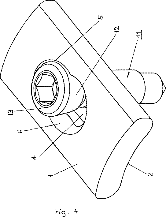
図4には、図2の骨板を備えた固定装置が示されており、それは、ねじ頭13に設けられた、骨板の雌ねじに対応する雄ねじ12によって、骨ねじ11を把持している。
骨ねじ11は、自己穿孔性及び/またはタッピンねじとして構成されているのが好適である。
【図面の簡単な説明】
【図1】 円形の孔及び細長い孔からなる組合せ孔の概念図である。
【図2】 三次元構造をもった組合せ孔を有する本発明の骨板の上面図である。
【図3】 図2の組合せ孔の円形孔の縦断面図である。
【図4】 一体化されたねじによって骨ねじが組合せ孔中にはめ込まれている本発明の骨板を示す斜視図である。[0001]
(Technical field)
The invention relates to a bone plate according to the superordinate concept of claim 1 and to a fixation device using such a bone plate according to the superordinate concept of claim 20.
[0002]
(Background technology)
Basically, two methods of osteosynthesis using a bone plate are known.
The first method corresponds to “rigid osteosynthesis”. Rigid osteosynthesis is applied in the treatment of joint fractures, simple diaphyseal fractures (when nailing cannot be performed) and osteotomy. In addition to the anatomical reduction potential, the bone itself supports the stability of the osteosynthesis, thereby making the limb load earlier and less painful. The advantages of a stable fracture treatment can also be seen when bone circulation is severely reduced by trauma. Stable treatment of fractures in the case of treatment of pseudo-joints or if there is infection so that the bone can heal and the infection does not cause further stimulation due to instability of the fracture space Must.
[0003]
The second method corresponds to “soft (flexible) osteosynthesis”. The greatest advantage of soft (biological) osteosynthesis can be seen during the treatment of fractures in the diaphysis of the long bone. In the case of this fracture, the goal is to keep the bone length as well as the bone ends (joints) in the correct position relative to each other. In this case, the fracture zone is not directly fixed or treated, but this does not further compromise the circulation of this zone. The bone plate functions like a fixation intramedullary nail that is fixed only at the metaphysis.
[0004]
Now, considering these extremes of osteosynthesis using plates, you can see how far they are apart. Not all fractures can be allocated to the above two osteosynthesis schemes, and surgeons often have to compromise because they cannot obtain an implant that can combine both methods without compromise. It is. Such a combination can be used, for example, when a fracture joint is compressible by a bone plate using a traction screw and the entire joint part is connected to the diaphysis by an angle stable screw via an internal fixture. Would be effective. For example, the bone plate can be fixed to the diaphyseal piece by a screw having a stable axial direction and angle, and is supported by a plate traction screw passing through the fracture portion in the diaphysis region. This would be the case for atrophic bone that can be easily fixed. Thanks to this procedure, primary fracture stabilization can be achieved.
[0005]
From this situation, bone grafts for both types of osteosynthesis were developed and marketed. Both groups of implants are structured to be optimal for each method. Therefore, the disadvantage of both these systems is that they cannot be combined.
[0006]
From US Pat. No. 5,709,686 to TALOS et al., Such a combination plate is known, in which a cylindrical screw is provided in the middle of the elongated hole. The disadvantages of this known board are:
1) Since the screw is located at the center in the elongated hole of the plate, the screw region is limited to 60 ° to 179 °.
2) Since the screw is located at the center position in the elongated hole (fixed hole) of the plate, the lateral edge of the elongated hole may spread.
3) Since the screw is cylindrical, a specially configured screw head must be used, which can stretch the surface of the plate when screwed.
[0007]
(Disclosure of the Invention)
Here, the present invention takes measures. It is an object of the present invention to provide a bone plate that combines both osteosynthesis methods on its own without causing limitations in both intact plate treatment methods. The present invention must therefore make it possible to use the plate without compromising as a compression plate and as a so-called internal fixture.
The present invention solves the given problem by providing a bone plate having the features of claim 1.
[0008]
The elongated hole as used in the present invention refers to a hole having a diameter measured in the direction of the longitudinal axis of the plate that is larger than the diameter of this hole measured perpendicular to the longitudinal axis of the plate. Thus, such elongated holes can be configured in an oval, elliptical, or rectangular shape and can include combinations of such forms; the only shape that should be excluded from this definition is a circular hole It is.
[0009]
In a preferred embodiment, the circular hole of the combination hole comprises a three-dimensional structure, preferably a three-dimensional structure in the form of an internal thread or lamella or lip. The three-dimensional structure may be provided in a single plane parallel to the top surface of the bone plate or in a plurality of planes parallel to the top surface.
[0010]
The diameter d of the circular hole is preferably smaller than the minor axis b of the elongated hole of the combination hole. Typically, d is 5-25% less than b.
Using a plate as an internal fixture results in greatly increased mechanical strain at the plate-screw interface. This is because the fracture portion is fixed by friction between the plate and the bone without the plate being pressed against the bone. In one preferred embodiment, the above-described overload is addressed by allowing the screw to span at least 180 ° in the elongated hole, thus allowing the screw head-screw to encompass at least this angular range. . This situation is particularly important in the case of thin bone plates.
[0011]
A further preferred configuration consists of tapering a three-dimensional structure, for example in the form of an internal thread in the combination hole, towards the lower surface of the bone plate, preferably conically. It has the advantage that the screw is fixed by means of the conical thread of the bone plate and the corresponding conical thread of the screw head used. This type of fixation is particularly important when trying to use self-piercing screws. Thanks to the conical thread on the screw head, the position of the plate does not need to be considered in the process of the screw being introduced into the bone. Only after the conical thread on the screw head engages the female thread in the elongated hole in the plate, the screw stops (blocks). The thread of the conical screw head automatically comes to the center of the conical thread of the plate, even though the beginning of the thread occurs in the conical hole and bone of the plate.
[0012]
When the conical screw is tightened, a radial force is generated in the plate hole. In order to fully absorb these forces, the conical holes in the plate must have sufficient stability. In one preferred embodiment, it is more effective that the internal thread tapered conically toward the lower surface of the bone plate has a cone angle of 5 ° to 20 °, typically 10 °.
[0013]
In a further preferred embodiment of the invention, an internal thread is provided at one of the ends of the elongated hole when viewed in the direction of the longitudinal axis of the plate. This position makes it possible in construction to realize an enlarged thread region, which spans for example 190 ° to 280 °, preferably 200 ° to 250 ° of the geometric solid formed thereby. .
[0014]
If the elongated hole is configured in a conical shape, different values can be obtained by measuring the extent of the internal thread on the lower surface of the plate and that on the upper surface. When measured at the top surface, the area of the screw should preferably be between 180 ° and 230 °, and when measured at the bottom surface should be between 200 ° and 270 °.
[0015]
In a further preferred embodiment, the terminal conical screw in the elongated hole (fixing hole) is provided at the end close to the center of the plate. This has the advantage that the fixing function of the plate fixing hole is not impaired.
[0016]
In a further preferred embodiment, the combination hole has a concave, preferably spherical, enlargement in its upper part facing the upper surface for receiving a bone screw with a spherical head. . This concave, spherical enlargement is optimally adapted to the spherical screw head of a conventional bone screw. This is particularly necessary to achieve fracture compression, but is beneficial when the bone screw is fitted eccentrically.
[0017]
In a further preferred embodiment, the lower surface is configured to be concave. Due to the concave lower surface of the plate, the plate better fits the round bone cross-section of the tibia, femur, humerus and forearm. The concave embodiment of the hole in the lower surface of the plate allows a conventional bone screw to be inserted diagonally through the hole in the plate. It is particularly important for capturing and grasping small bone fragments that must be drawn to the plate.
[0018]
In a further preferred embodiment, in order to achieve the highest possible stability, the internal thread extends from the lower surface to the upper surface over the entire height of the bone plate.
In a further preferred embodiment, the combination hole has an extension in the area below the bone plate in the region where the three-dimensional structure is not provided , so that the bone screw can be secured. Deviation is possible.
[0019]
A further embodiment further comprises at least one bone screw in addition to the bone plate of the present invention; it has a structure provided in the screw head, for example in the form of a male screw, corresponding to a three-dimensional structure. Preferably, the male screw is configured as a tapping screw or a self-piercing screw. When the bone plate is applied as a compression plate, the fixed hole configuration of the plate hole is not negatively affected by the conical screw hole at the end. The advantage of the conical configuration of the screw hole is that the screw is screwed into the bone independently of the plate without having to consider the position of the plate, in which case the screw is correspondingly configured in a conical shape Only when a threaded screw head is screwed tightly into the female thread of the corresponding plate is it joined to the plate. This is particularly advantageous when using self-piercing, tapping screws.
[0020]
(Best Mode for Carrying Out the Invention)
The invention and its development will be explained in more detail below with the aid of partial conceptual diagrams of several embodiments.
[0021]
The bone plate of the present invention shown in FIG. 2 has an upper surface 1, a
The diameter of the
[0022]
As conceptually shown in FIG. 1, the
[0023]
The
The
[0024]
As shown in FIG. 3, a three-
In the preferred embodiment of the invention shown in FIGS. 2 and 3, a female thread is provided at the end of the
Depending on the diameter of the
[0025]
[Table 1]
FIG. 4 shows a fixation device comprising the bone plate of FIG. 2, which grips the
The
[Brief description of the drawings]
FIG. 1 is a conceptual diagram of a combination hole composed of a circular hole and an elongated hole.
FIG. 2 is a top view of a bone plate of the present invention having a combination hole with a three-dimensional structure.
3 is a longitudinal sectional view of a circular hole of the combination hole of FIG.
FIG. 4 is a perspective view showing a bone plate of the present invention in which a bone screw is fitted into a combination hole by an integrated screw.
Claims (18)
前記孔(4)の少なくとも一つが、
a)直径d及び対称中心Skを有する円形の孔(14)と
b)板の長手軸線の方向にのびる長軸a及びそれに垂直にのびる短軸bを有する対称中心Slの細長い孔(24)との組合せから成り、
前記対称中心SkとSlとの距離Aが和d/2+a/2よりも小さく、前記両対称中心が板の長手軸線(3)の領域内に配置され、
c)前記円形の孔(14)が三次元構造(5)を備え、
d)前記三次元構造(5)が、雌ねじあるいはラメラまたはリップの形であることを
特徴とする前記骨板。A plurality of upper surfaces (1), a lower surface (2) to be in contact with the bone, and a bone screw (11) are arranged along the longitudinal axis (3) of the plate and connect a plurality of upper and lower surfaces (1; 2). A bone plate with a hole (4),
At least one of the holes (4) is
circular hole (14) and b) an elongated hole of the center of symmetry S l, having a length axis a and minor axis b extending vertically thereto extending in the direction of the longitudinal axis of the plate having a) a diameter d and a center of symmetry S k (24 )) And
A distance A between the symmetry centers S k and S l is smaller than the sum d / 2 + a / 2, and the symmetry centers are arranged in the region of the longitudinal axis (3) of the plate;
c) the circular hole (14) comprises a three-dimensional structure (5);
d) The bone plate characterized in that the three-dimensional structure (5) is in the form of an internal thread or a lamella or lip .
0.5(d/2+a/2)<A<1.0(d/2+a/2)
なる条件に従っていることを特徴とする請求項1〜13のいずれかに記載の骨板。The distance A between the symmetry centers S k and S l is
0.5 (d / 2 + a / 2) <A <1.0 (d / 2 + a / 2)
The bone plate according to any one of claims 1 to 13 , characterized in that:
Applications Claiming Priority (1)
| Application Number | Priority Date | Filing Date | Title |
|---|---|---|---|
| PCT/CH2000/000037 WO2001054601A1 (en) | 2000-01-27 | 2000-01-27 | Bone plate |
Publications (3)
| Publication Number | Publication Date |
|---|---|
| JP2003521303A JP2003521303A (en) | 2003-07-15 |
| JP2003521303A5 JP2003521303A5 (en) | 2007-05-31 |
| JP4162408B2 true JP4162408B2 (en) | 2008-10-08 |
Family
ID=4358034
Family Applications (1)
| Application Number | Title | Priority Date | Filing Date |
|---|---|---|---|
| JP2001555581A Expired - Lifetime JP4162408B2 (en) | 2000-01-27 | 2000-01-27 | Bone plate |
Country Status (18)
| Country | Link |
|---|---|
| US (3) | US6669701B2 (en) |
| EP (1) | EP1255498B1 (en) |
| JP (1) | JP4162408B2 (en) |
| KR (1) | KR100706291B1 (en) |
| CN (1) | CN100415182C (en) |
| AR (1) | AR031369A1 (en) |
| AT (1) | ATE310457T1 (en) |
| AU (1) | AU775910B2 (en) |
| BR (1) | BR0017018A (en) |
| CA (1) | CA2398372C (en) |
| DE (1) | DE50011716D1 (en) |
| DK (1) | DK1255498T3 (en) |
| ES (1) | ES2253202T3 (en) |
| HK (1) | HK1048750B (en) |
| MX (1) | MXPA02007226A (en) |
| MY (1) | MY127200A (en) |
| TW (1) | TW519484B (en) |
| WO (1) | WO2001054601A1 (en) |
Cited By (2)
| Publication number | Priority date | Publication date | Assignee | Title |
|---|---|---|---|---|
| WO2019240102A1 (en) | 2018-06-12 | 2019-12-19 | オリンパステルモバイオマテリアル株式会社 | Bone plate and bone plate kit |
| US10653466B2 (en) | 2003-05-30 | 2020-05-19 | DePuy Synthes Products, Inc. | Bone plate |
Families Citing this family (202)
| Publication number | Priority date | Publication date | Assignee | Title |
|---|---|---|---|---|
| EP1158915B1 (en) * | 1999-03-09 | 2004-09-01 | SYNTHES AG Chur | Bone plate |
| DE60007758T2 (en) * | 1999-09-13 | 2004-09-23 | Synthes Ag Chur, Chur | BONE PLATE DEVICE |
| JP4162408B2 (en) | 2000-01-27 | 2008-10-08 | ジンテーズ ゲゼルシャフト ミト ベシュレンクテル ハフツング | Bone plate |
| US7717945B2 (en) | 2002-07-22 | 2010-05-18 | Acumed Llc | Orthopedic systems |
| US7537604B2 (en) | 2002-11-19 | 2009-05-26 | Acumed Llc | Bone plates with slots |
| US7189237B2 (en) | 2002-11-19 | 2007-03-13 | Acumed Llc | Deformable bone plates |
| US20050240187A1 (en) | 2004-04-22 | 2005-10-27 | Huebner Randall J | Expanded fixation of bones |
| US7090676B2 (en) | 2002-11-19 | 2006-08-15 | Acumed Llc | Adjustable bone plates |
| KR100787209B1 (en) * | 2001-05-28 | 2007-12-21 | 신세스 게엠바하 | Graft plate for fixing proximal humerus fracture |
| US7780710B2 (en) | 2004-01-23 | 2010-08-24 | Depuy Products, Inc. | System for stabilization of fractures of convex articular bone surfaces including subchondral support structure |
| US7938850B2 (en) | 2002-05-30 | 2011-05-10 | Depuy Products, Inc. | Nail plate |
| EP1542602B1 (en) | 2002-07-22 | 2010-11-17 | Acumed LLC | Bone fusion system |
| US7179260B2 (en) | 2003-09-29 | 2007-02-20 | Smith & Nephew, Inc. | Bone plates and bone plate assemblies |
| US7722653B2 (en) * | 2003-03-26 | 2010-05-25 | Greatbatch Medical S.A. | Locking bone plate |
| WO2004084701A2 (en) | 2003-03-26 | 2004-10-07 | Swiss Orthopedic Solutions Sa | Locking bone plate |
| US7905883B2 (en) | 2003-03-26 | 2011-03-15 | Greatbatch Medical S.A. | Locking triple pelvic osteotomy plate and method of use |
| US7776076B2 (en) * | 2004-05-11 | 2010-08-17 | Synthes Usa, Llc | Bone plate |
| CN100553577C (en) * | 2003-06-20 | 2009-10-28 | 精密医疗责任有限公司 | System for Intraoperatively Tapping Bone Plates |
| US11259851B2 (en) | 2003-08-26 | 2022-03-01 | DePuy Synthes Products, Inc. | Bone plate |
| JP4999327B2 (en) | 2003-08-26 | 2012-08-15 | ジンテーズ ゲゼルシャフト ミト ベシュレンクテル ハフツング | Bone plate |
| US7635365B2 (en) | 2003-08-28 | 2009-12-22 | Ellis Thomas J | Bone plates |
| ATE375762T1 (en) | 2003-09-08 | 2007-11-15 | Synthes Gmbh | DEVICE FOR BONE FIXATION |
| US20050055024A1 (en) | 2003-09-08 | 2005-03-10 | James Anthony H. | Orthopaedic implant and screw assembly |
| US8105367B2 (en) | 2003-09-29 | 2012-01-31 | Smith & Nephew, Inc. | Bone plate and bone plate assemblies including polyaxial fasteners |
| WO2005037114A1 (en) * | 2003-10-17 | 2005-04-28 | Acumed Llc | Systems for distal radius fixation |
| EP1677693B1 (en) | 2003-10-30 | 2009-04-15 | Synthes GmbH | Bone plate |
| CA2544742A1 (en) * | 2003-11-05 | 2005-05-19 | Koenigsee Implantate Und Instrumente Zur Osteosynthese Gmbh | Plate used to stabilise distal radius fractures |
| US8182485B1 (en) | 2003-11-21 | 2012-05-22 | Toby Orthopaedics, Llc | Fracture fixation system |
| US7947043B2 (en) * | 2004-01-20 | 2011-05-24 | Depuy Products, Inc. | Intramedullary nail and associated method |
| EP1713409B1 (en) | 2004-01-23 | 2013-01-16 | Biomet C.V. | System for stabilization of fractures of convex articular bone surfaces including subchondral support structure |
| US11291484B2 (en) | 2004-01-26 | 2022-04-05 | DePuy Synthes Products, Inc. | Highly-versatile variable-angle bone plate system |
| US7637928B2 (en) | 2004-01-26 | 2009-12-29 | Synthes Usa, Llc | Variable angle locked bone fixation system |
| US8574268B2 (en) | 2004-01-26 | 2013-11-05 | DePuy Synthes Product, LLC | Highly-versatile variable-angle bone plate system |
| US20050182403A1 (en) * | 2004-02-04 | 2005-08-18 | Wellong Instruments Co., Ltd. | Fixture for spines |
| US20050192578A1 (en) * | 2004-02-26 | 2005-09-01 | Horst Steven P. | Bone plates with locking apertures |
| WO2006091827A2 (en) | 2005-02-25 | 2006-08-31 | Regents Of The University Of California | Device and template for canine humeral slide osteotomy |
| USD536453S1 (en) | 2004-03-25 | 2007-02-06 | Precimed S.A. | Bone plate |
| US20080045960A1 (en) * | 2004-03-25 | 2008-02-21 | Bruecker Kenneth | Locking tpo plate and method of use |
| US7942913B2 (en) | 2004-04-08 | 2011-05-17 | Ebi, Llc | Bone fixation device |
| GB2414673A (en) * | 2004-06-02 | 2005-12-07 | Vineet Dev Tandon | A bone plate |
| US20050277937A1 (en) * | 2004-06-10 | 2005-12-15 | Leung Takkwong R | Bone plating system |
| US7229445B2 (en) * | 2004-06-21 | 2007-06-12 | Synthes (Usa) | Bone plate with bladed portion |
| US20060015101A1 (en) * | 2004-07-15 | 2006-01-19 | Wright Medical Technology, Inc. | Intramedullary fixation assembly and devices and methods for installing the same |
| US8043297B2 (en) | 2004-11-03 | 2011-10-25 | Synthes Usa, Llc | Aiming arm for bone plates |
| US7648508B2 (en) * | 2004-11-30 | 2010-01-19 | Stryker Trauma S.A. | Bone plating implants, instruments and methods |
| US20060149264A1 (en) * | 2004-12-20 | 2006-07-06 | Castaneda Javier E | Screw locking systems for bone plates |
| US7527640B2 (en) | 2004-12-22 | 2009-05-05 | Ebi, Llc | Bone fixation system |
| DE102005004841B4 (en) * | 2004-12-30 | 2009-10-29 | Königsee Implantate und Instrumente zur Osteosynthese GmbH | Osteosynthesis plate with a variety of holes for receiving bone screws |
| CA2596266C (en) | 2005-01-28 | 2015-03-31 | Depuy Products, Inc. | Nail plate system |
| US20060195085A1 (en) * | 2005-02-01 | 2006-08-31 | Inion Ltd. | System and method for stabilizing spine |
| EP1712197B1 (en) | 2005-04-11 | 2009-01-14 | aap Implantate AG | Bone plate |
| US8382807B2 (en) | 2005-07-25 | 2013-02-26 | Smith & Nephew, Inc. | Systems and methods for using polyaxial plates |
| ES2523435T3 (en) | 2005-07-25 | 2014-11-25 | Smith And Nephew, Inc. | Polyaxial Plates |
| US20070055248A1 (en) * | 2005-07-29 | 2007-03-08 | Zlowodzki Michal P | Bone plating system for treatment of hip fractures |
| US20070093822A1 (en) | 2005-09-28 | 2007-04-26 | Christof Dutoit | Apparatus and methods for vertebral augmentation using linked expandable bodies |
| US7955364B2 (en) | 2005-09-21 | 2011-06-07 | Ebi, Llc | Variable angle bone fixation assembly |
| CA2626145A1 (en) * | 2005-10-25 | 2007-05-03 | Anthem Orthopaedics Llc | Bone fastening assembly and bushing and screw for use therewith |
| US8551145B2 (en) * | 2005-12-19 | 2013-10-08 | Mayo Foundation For Medical Education And Research | Anterior adherent thoracolumbar spine plate |
| US8100952B2 (en) * | 2005-12-22 | 2012-01-24 | Anthem Orthopaedics Llc | Drug delivering bone plate and method and targeting device for use therewith |
| US20070162132A1 (en) | 2005-12-23 | 2007-07-12 | Dominique Messerli | Flexible elongated chain implant and method of supporting body tissue with same |
| ATE380512T1 (en) | 2005-12-23 | 2007-12-15 | Aap Implantate Ag | BONE PLATE |
| US20070198016A1 (en) * | 2006-02-21 | 2007-08-23 | Osteomed, L.P. | Compression stabilizing spacers |
| US8523921B2 (en) | 2006-02-24 | 2013-09-03 | DePuy Synthes Products, LLC | Tibial plateau leveling osteotomy plate |
| US7951178B2 (en) * | 2006-04-03 | 2011-05-31 | Acumed Llc | Bone plates with hybrid apertures |
| US8926675B2 (en) * | 2006-04-11 | 2015-01-06 | Biomet Manufacturing, Llc | Contoured bone plate |
| ES2312064T3 (en) * | 2006-05-26 | 2009-02-16 | Aap Implantate Ag | OSTEOSYNTHESIS PLATE. |
| WO2008007194A2 (en) | 2006-07-07 | 2008-01-17 | Precimed, S.A. | Bone plate with complex, adjacent holes joined by a bend relief zone |
| CN101505670B (en) | 2006-07-07 | 2015-05-20 | 瑞博奥公司 | Bone plate with complex, adjacent holes joined by a relief-space |
| US20080086136A1 (en) * | 2006-08-30 | 2008-04-10 | Bednar Drew A | Percutaneous hip system |
| US8114080B2 (en) * | 2006-09-27 | 2012-02-14 | Depuy Products, Inc. | Flexible bone fixation device |
| US20080177330A1 (en) * | 2006-10-24 | 2008-07-24 | Ralph James D | Self-locking screws for medical implants |
| FR2908627B1 (en) * | 2006-11-20 | 2009-07-03 | Tornier Sas | PROTHETIC OR OSTEOSYNTHESIS DEVICE WITH A SLICED OLIVE |
| JP2010512981A (en) * | 2006-12-19 | 2010-04-30 | スモール・ボーン・イノベーションズ・インコーポレーテッド | Locking fixing system and lug tool |
| US9308031B2 (en) | 2007-01-26 | 2016-04-12 | Biomet Manufacturing, Llc | Lockable intramedullary fixation device |
| US9320551B2 (en) | 2007-01-26 | 2016-04-26 | Biomet Manufacturing, Llc | Lockable intramedullary fixation device |
| US8142432B2 (en) * | 2007-02-05 | 2012-03-27 | Synthes Usa, Llc | Apparatus for repositioning portions of fractured bone and method of using same |
| US7918853B2 (en) | 2007-03-20 | 2011-04-05 | Smith & Nephew, Inc. | Orthopaedic plate and screw assembly |
| WO2008116175A2 (en) | 2007-03-22 | 2008-09-25 | Novalign Orthopaedics, Inc. | Segmented intramedullary structure |
| EP2120752A1 (en) * | 2007-03-22 | 2009-11-25 | Synthes GmbH | Bone plate |
| US9072548B2 (en) | 2007-06-07 | 2015-07-07 | Anthem Orthopaedics Llc | Spine repair assembly |
| AR061999A1 (en) * | 2007-07-18 | 2008-08-10 | Pizzicara Mario Angel | BLOCKED PLATE OF COMBINED HOLES, STABILITY CONTROL AND DOUBLE ANGULATION, FOR UNION OF FRACTURED BONES |
| US9173042B2 (en) * | 2007-07-20 | 2015-10-27 | Cochlear Limited | Bone anchor fixture for a medical prosthesis |
| US20090177239A1 (en) * | 2007-08-06 | 2009-07-09 | Michael Castro | Cervical plate instrument kit |
| US8632545B2 (en) * | 2007-08-27 | 2014-01-21 | Adler Mediequip Private Limited | Bone plates and bone plate assemblies |
| US8728126B2 (en) * | 2008-03-10 | 2014-05-20 | Dennis L. Steffen | Bone fixation system and method |
| US20090228010A1 (en) * | 2008-03-10 | 2009-09-10 | Eduardo Gonzalez-Hernandez | Bone fixation system |
| EP2282690A4 (en) | 2008-04-17 | 2017-06-14 | Toby Orthopaedics, Llc | Soft tissue attachment system and clip |
| FR2936700B1 (en) | 2008-10-02 | 2012-04-13 | Memometal Technologies | ORTHOPEDIC IMPLANT IN THE FORM OF A PLATE TO BE FIXED BETWEEN TWO BONE PARTS |
| US12285197B2 (en) | 2008-10-10 | 2025-04-29 | Acumed Llc | Bone fixation system with opposed mounting portions |
| US8246664B2 (en) | 2009-02-24 | 2012-08-21 | Osteomed Llc | Multiple bone fusion plate |
| ITTO20090551A1 (en) * | 2009-07-22 | 2011-01-23 | Traumavet S R L | PLATE OF OSTEOSYNTHESIS FOR FEMORAL FRACTURES |
| US8366719B2 (en) | 2009-03-18 | 2013-02-05 | Integrated Spinal Concepts, Inc. | Image-guided minimal-step placement of screw into bone |
| US8506608B2 (en) * | 2009-03-24 | 2013-08-13 | Douglas Cerynik | Orthopedic fixation device with bioresorbable layer |
| US20100256687A1 (en) | 2009-04-01 | 2010-10-07 | Merete Medical Gmbh | Fixation Device and Method of Use for a Ludloff Osteotomy Procedure |
| DE102009016394B4 (en) | 2009-04-07 | 2016-02-11 | Merete Medical Gmbh | Device for stable-angle fixation and compression of a fracture site or osteotomy on a bone |
| US8529608B2 (en) | 2009-04-28 | 2013-09-10 | Osteomed Llc | Bone plate with a transfixation screw hole |
| CA2765376C (en) | 2009-06-30 | 2017-06-06 | Smith & Nephew, Inc. | Orthopaedic implant and fastener assembly |
| US8449544B2 (en) * | 2009-06-30 | 2013-05-28 | Smith & Nephew, Inc. | Orthopaedic implant and fastener assembly |
| US8834536B2 (en) | 2009-07-16 | 2014-09-16 | Nexxt Spine, LLC | Cervical plate fixation system |
| US9095444B2 (en) | 2009-07-24 | 2015-08-04 | Warsaw Orthopedic, Inc. | Implant with an interference fit fastener |
| EP2477566B1 (en) | 2009-09-14 | 2017-03-22 | Synthes GmbH | Variable angle compression plate |
| CN102630155B (en) | 2009-09-18 | 2015-11-25 | 拜欧米特公司 | Disposable shaping surgery kit and parts |
| US10390867B2 (en) | 2009-09-18 | 2019-08-27 | Biomet C.V. | Bone plate system and method |
| US8496692B2 (en) | 2009-09-21 | 2013-07-30 | Jmea Corporation | Locking securing member |
| CA2781155C (en) | 2009-12-11 | 2017-12-19 | Synthes Usa, Llc | Mandibular fixation plate |
| US8568417B2 (en) | 2009-12-18 | 2013-10-29 | Charles River Engineering Solutions And Technologies, Llc | Articulating tool and methods of using |
| EP2515780A4 (en) * | 2009-12-22 | 2014-10-15 | Toby Orthopaedics Llc | Bone plate and tool assembly and method for use thereof |
| EP2515779B1 (en) | 2009-12-22 | 2016-03-02 | Merete Medical GmbH | Bone plate system for osteosynthesis |
| US20110218580A1 (en) * | 2010-03-08 | 2011-09-08 | Stryker Trauma Sa | Bone fixation system with curved profile threads |
| ES2394257T3 (en) | 2010-03-10 | 2013-01-30 | Aap Implantate Ag | Bone plate system |
| US20110245871A1 (en) * | 2010-04-06 | 2011-10-06 | Williams Lytton A | Crosslink element and bender for spine surgery procedures |
| DE102010025000B4 (en) | 2010-06-24 | 2016-01-21 | Aap Implantate Ag | bone plate |
| DE102010025001B4 (en) | 2010-06-24 | 2016-08-04 | Aap Implantate Ag | Fixation system with bone plate and bone screw |
| DE102010064626B3 (en) | 2010-06-24 | 2018-05-17 | Aap Implantate Ag | bone plate |
| DE102010025702B4 (en) | 2010-06-30 | 2016-08-18 | Aap Implantate Ag | Fixation system for bone with bone plate and bone screws |
| US8753396B1 (en) | 2010-09-13 | 2014-06-17 | Theken Spine, Llc | Intervertebral implant having back-out prevention feature |
| US8961573B2 (en) | 2010-10-05 | 2015-02-24 | Toby Orthopaedics, Inc. | System and method for facilitating repair and reattachment of comminuted bone portions |
| US8870963B2 (en) | 2010-10-27 | 2014-10-28 | Toby Orthopaedics, Inc. | System and method for fracture replacement of comminuted bone fractures or portions thereof adjacent bone joints |
| US8551095B2 (en) | 2011-02-02 | 2013-10-08 | Bionet Manufacturing, LLC | Bone plate having combination locking and compression screw holes |
| US8709092B2 (en) | 2011-02-16 | 2014-04-29 | Genesis Medical Devices, LLC | Periprosthetic fracture management enhancements |
| WO2012119146A2 (en) | 2011-03-03 | 2012-09-07 | Toby Orthopaedics, Llc | Anterior lesser tuberosity fixed angle fixation device and method of use associated therewith |
| US8672978B2 (en) | 2011-03-04 | 2014-03-18 | Zimmer Spine, Inc. | Transverse connector |
| EP2680767A1 (en) * | 2011-03-04 | 2014-01-08 | Synthes GmbH | Modular hook plate assembly |
| CN102688086A (en) * | 2011-03-24 | 2012-09-26 | 创生医疗器械(中国)有限公司 | Locking compression bone fracture plate |
| CN102688085A (en) * | 2011-03-24 | 2012-09-26 | 创生医疗器械(中国)有限公司 | Locking and pressurizing bone device and using method thereof |
| WO2012154496A2 (en) * | 2011-05-06 | 2012-11-15 | Smith & Nephew, Inc. | Targeting landmarks of orthopaedic devices |
| CN103717179B (en) | 2011-06-15 | 2017-08-08 | 史密夫和内修有限公司 | Variable Angle Locking Implants |
| DE202011051165U1 (en) | 2011-08-31 | 2011-11-14 | Merete Medical Gmbh | Anatomically adapted, plantar bone plate and bone plate system |
| WO2013036362A1 (en) * | 2011-09-06 | 2013-03-14 | Synthes Usa, Llc | Pancarpal arthrodesis bone plate |
| EP2760354B1 (en) | 2011-09-30 | 2019-05-08 | Acute Innovations, Llc | Bone fixation system with opposed mounting portions |
| DE202011106835U1 (en) | 2011-10-14 | 2012-02-06 | Königsee Implantate GmbH | bone plate |
| US9730797B2 (en) | 2011-10-27 | 2017-08-15 | Toby Orthopaedics, Inc. | Bone joint replacement and repair assembly and method of repairing and replacing a bone joint |
| US9271772B2 (en) | 2011-10-27 | 2016-03-01 | Toby Orthopaedics, Inc. | System and method for fracture replacement of comminuted bone fractures or portions thereof adjacent bone joints |
| US9402667B2 (en) | 2011-11-09 | 2016-08-02 | Eduardo Gonzalez-Hernandez | Apparatus and method for use of the apparatus for fracture fixation of the distal humerus |
| WO2013113015A1 (en) | 2012-01-26 | 2013-08-01 | Acute Innovations Llc | Clip for rib stabilization |
| US9681902B2 (en) | 2012-02-13 | 2017-06-20 | Stryker European Holdings I, Llc | Attachment device for a bone plate |
| DE102012103894B4 (en) | 2012-05-03 | 2016-10-27 | Merete Medical Gmbh | Bone plate system for osteosynthesis |
| US20140148859A1 (en) * | 2012-11-27 | 2014-05-29 | Solana Surgical, Llc | Orthopedic fusion plate and compression screw |
| US9283008B2 (en) | 2012-12-17 | 2016-03-15 | Toby Orthopaedics, Inc. | Bone plate for plate osteosynthesis and method for use thereof |
| US9433454B2 (en) | 2013-03-14 | 2016-09-06 | Amei Technologies, Inc. | Variable angle screws, plates and systems |
| US9545276B2 (en) | 2013-03-15 | 2017-01-17 | Aristotech Industries Gmbh | Fixation device and method of use for a lapidus-type plantar hallux valgus procedure |
| US9333014B2 (en) | 2013-03-15 | 2016-05-10 | Eduardo Gonzalez-Hernandez | Bone fixation and reduction apparatus and method for fixation and reduction of a distal bone fracture and malunion |
| US9468479B2 (en) * | 2013-09-06 | 2016-10-18 | Cardinal Health 247, Inc. | Bone plate |
| USD745162S1 (en) | 2014-01-27 | 2015-12-08 | Merete Medical Gmbh | Bone plate |
| US9987061B2 (en) | 2014-01-28 | 2018-06-05 | Biomet C.V. | Implant with suspended locking holes |
| US11240613B2 (en) | 2014-01-30 | 2022-02-01 | Cochlear Limited | Bone conduction implant |
| US10226287B2 (en) | 2014-03-31 | 2019-03-12 | Association For The Advancement Of Musculoskeletal | Bone plate with versatile screw holes |
| WO2016032273A1 (en) * | 2014-08-28 | 2016-03-03 | 주식회사 케이씨스 | Bone plate for fracture |
| JP6527591B2 (en) | 2015-02-26 | 2019-06-05 | メダルティス・ホールディング・アクチェンゲゼルシャフトMedartis Holding Ag | Bone plate and surgical kit for fixing bone fragments |
| WO2016172142A1 (en) | 2015-04-21 | 2016-10-27 | Mwi Veterinary Supply Co. | Tplo bone plate |
| US10687874B2 (en) | 2015-08-27 | 2020-06-23 | Globus Medical, Inc | Proximal humeral stabilization system |
| US11197682B2 (en) | 2015-08-27 | 2021-12-14 | Globus Medical, Inc. | Proximal humeral stabilization system |
| US11076898B2 (en) | 2015-08-27 | 2021-08-03 | Globus Medical, Inc. | Proximal humeral stabilization system |
| GB2557840B (en) | 2015-09-18 | 2021-07-21 | Smith & Nephew Inc | Bone plate |
| US10130402B2 (en) | 2015-09-25 | 2018-11-20 | Globus Medical, Inc. | Bone fixation devices having a locking feature |
| US9974581B2 (en) | 2015-11-20 | 2018-05-22 | Globus Medical, Inc. | Expandable intramedullary systems and methods of using the same |
| WO2017096098A1 (en) * | 2015-12-01 | 2017-06-08 | Revivo Medical, Llc | Bone fixation apparatus with fastener securement mechanism and methods of use |
| US9795411B2 (en) | 2016-03-02 | 2017-10-24 | Globus Medical, Inc. | Fixators for bone stabilization and associated systems and methods |
| US10531905B2 (en) | 2016-04-19 | 2020-01-14 | Globus Medical, Inc. | Implantable compression screws |
| EP3257458A1 (en) * | 2016-06-17 | 2017-12-20 | ORTHOFIX S.r.l. | Bone plate for epiphysiodesis |
| US10420596B2 (en) | 2016-08-17 | 2019-09-24 | Globus Medical, Inc. | Volar distal radius stabilization system |
| US11432857B2 (en) | 2016-08-17 | 2022-09-06 | Globus Medical, Inc. | Stabilization systems |
| US10687873B2 (en) | 2016-08-17 | 2020-06-23 | Globus Medical Inc. | Stabilization systems |
| US11213327B2 (en) | 2016-08-17 | 2022-01-04 | Globus Medical, Inc. | Fracture plates, systems, and methods |
| US11331128B2 (en) | 2016-08-17 | 2022-05-17 | Globus Medical Inc. | Distal radius stabilization system |
| US11141204B2 (en) | 2016-08-17 | 2021-10-12 | Globus Medical Inc. | Wrist stabilization systems |
| US10575884B2 (en) | 2016-08-17 | 2020-03-03 | Globus Medical, Inc. | Fracture plates, systems, and methods |
| US11197701B2 (en) | 2016-08-17 | 2021-12-14 | Globus Medical, Inc. | Stabilization systems |
| US10383668B2 (en) | 2016-08-17 | 2019-08-20 | Globus Medical, Inc. | Volar distal radius stabilization system |
| US10751098B2 (en) | 2016-08-17 | 2020-08-25 | Globus Medical Inc. | Stabilization systems |
| US10820930B2 (en) | 2016-09-08 | 2020-11-03 | DePuy Synthes Products, Inc. | Variable angle bone plate |
| US10624686B2 (en) | 2016-09-08 | 2020-04-21 | DePuy Synthes Products, Inc. | Variable angel bone plate |
| US10905476B2 (en) | 2016-09-08 | 2021-02-02 | DePuy Synthes Products, Inc. | Variable angle bone plate |
| US10299847B2 (en) | 2016-09-22 | 2019-05-28 | Globus Medical, Inc. | Systems and methods for intramedullary nail implantation |
| US10881438B2 (en) | 2017-03-10 | 2021-01-05 | Globus Medical, Inc. | Clavicle fixation system |
| US10368928B2 (en) | 2017-03-13 | 2019-08-06 | Globus Medical, Inc. | Bone stabilization systems |
| US10905477B2 (en) | 2017-03-13 | 2021-02-02 | Globus Medical, Inc. | Bone stabilization systems |
| US10779867B2 (en) | 2017-04-06 | 2020-09-22 | Extremity Medical Llc | Orthopedic plate with modular peg and compression screw |
| US10856920B2 (en) | 2017-09-13 | 2020-12-08 | Globus Medical Inc. | Bone stabilization systems |
| US11096730B2 (en) | 2017-09-13 | 2021-08-24 | Globus Medical Inc. | Bone stabilization systems |
| US12279795B2 (en) | 2017-09-13 | 2025-04-22 | Globus Medical, Inc. | Bone stabilization systems |
| US11071570B2 (en) | 2018-03-02 | 2021-07-27 | Globus Medical, Inc. | Distal tibial plating system |
| US11224468B2 (en) | 2018-03-02 | 2022-01-18 | Globus Medical, Inc. | Distal tibial plating system |
| US11026727B2 (en) | 2018-03-20 | 2021-06-08 | DePuy Synthes Products, Inc. | Bone plate with form-fitting variable-angle locking hole |
| US10772665B2 (en) | 2018-03-29 | 2020-09-15 | DePuy Synthes Products, Inc. | Locking structures for affixing bone anchors to a bone plate, and related systems and methods |
| US11141172B2 (en) | 2018-04-11 | 2021-10-12 | Globus Medical, Inc. | Method and apparatus for locking a drill guide in a polyaxial hole |
| US11013541B2 (en) | 2018-04-30 | 2021-05-25 | DePuy Synthes Products, Inc. | Threaded locking structures for affixing bone anchors to a bone plate, and related systems and methods |
| US10828076B2 (en) | 2018-05-17 | 2020-11-10 | Biedermann Technologies Gmbh & Co. Kg | Bone fixation assembly with enlarged angle of inclination for a bone anchor to a favored side |
| US10925651B2 (en) | 2018-12-21 | 2021-02-23 | DePuy Synthes Products, Inc. | Implant having locking holes with collection cavity for shavings |
| US11202663B2 (en) | 2019-02-13 | 2021-12-21 | Globus Medical, Inc. | Proximal humeral stabilization systems and methods thereof |
| US11944360B2 (en) | 2019-06-11 | 2024-04-02 | DePuy Synthes Products, Inc. | Deformable threaded locking structures, and related systems and methods |
| US11179180B2 (en) | 2019-06-11 | 2021-11-23 | DePuy Synthes Products, Inc. | Deformable threaded locking structures, and related systems and methods |
| US12185995B2 (en) | 2019-10-09 | 2025-01-07 | Globus Medical, Inc. | Bone stabilization systems |
| US11129627B2 (en) | 2019-10-30 | 2021-09-28 | Globus Medical, Inc. | Method and apparatus for inserting a bone plate |
| US11723647B2 (en) | 2019-12-17 | 2023-08-15 | Globus Medical, Inc. | Syndesmosis fixation assembly |
| WO2022090856A1 (en) | 2020-10-30 | 2022-05-05 | DePuy Synthes Products, Inc. | Bone plates having multi-use screw holes for locking and compression screws |
| US12178481B2 (en) * | 2021-01-22 | 2024-12-31 | DePuy Synthes Products, Inc. | Bone plates having multi-use combination holes for locking and dynamic compression, and related systems and methods |
| US11963847B2 (en) | 2021-11-03 | 2024-04-23 | DePuy Synthes Products, Inc. | TPLO plate compression system and method |
| US11950814B2 (en) * | 2022-01-04 | 2024-04-09 | Extremity Medical, Llc | Orthopedic plate with locking compression slot |
| US12064150B2 (en) | 2022-01-19 | 2024-08-20 | Globus Medical Inc. | System and method for treating bone fractures |
| US12478365B2 (en) | 2022-08-24 | 2025-11-25 | Globus Medical, Inc. | Systems, devices and methods for implanting suture buttons |
| US12402923B2 (en) | 2022-10-04 | 2025-09-02 | DePuy Synthes Products, Inc. | Offset hole for TPLO compression |
Family Cites Families (64)
| Publication number | Priority date | Publication date | Assignee | Title |
|---|---|---|---|---|
| USRE28841E (en) | 1966-06-22 | 1976-06-08 | Synthes A.G. | Osteosynthetic pressure plate construction |
| USRE31628E (en) | 1966-06-22 | 1984-07-10 | Synthes Ag | Osteosynthetic pressure plate construction |
| CH462375A (en) | 1966-06-22 | 1968-09-15 | Synthes Ag | Osteosynthetic pressure plate |
| US3596656A (en) | 1969-01-21 | 1971-08-03 | Bernd B Kaute | Fracture fixation device |
| US3716050A (en) * | 1971-02-11 | 1973-02-13 | F Johnston | Olecranon plate |
| US3779240A (en) | 1972-03-31 | 1973-12-18 | S Kondo | Compression plate for osteosynthesis |
| FR2233973A1 (en) | 1973-06-25 | 1975-01-17 | Chatin Robert | Osteosynthesis plate for femoral fracture surgery - has anchoring holes in ablong flat portion and widened blade |
| CH611147A5 (en) | 1977-01-07 | 1979-05-31 | Mueller Kurt | Osteosynthesis compression plate |
| CH613858A5 (en) | 1977-04-22 | 1979-10-31 | Straumann Inst Ag | |
| FR2405062A1 (en) | 1977-10-10 | 1979-05-04 | Dayan Robert | Surgical repair plate for lower fractures of femur - has concave cross section and enlarged end with staggered countersunk screw holes |
| FR2405705A1 (en) | 1977-10-14 | 1979-05-11 | Dayan Robert | Surgical repair plate for tibia upper end fracture - has elongated length with enlarged head and countersunk for fixing screws |
| FR2405706A1 (en) | 1977-10-14 | 1979-05-11 | Dayan Robert | Surgical repair plate for humerus lower end fracture - has end with unequal curved branches and countersunk holes for fixing screws |
| CH645013A5 (en) * | 1980-04-14 | 1984-09-14 | Wenk Wilh Ag | Osteosynthetic COMPRESSION PLATE. |
| CH651192A5 (en) | 1980-11-20 | 1985-09-13 | Synthes Ag | OSTEOSYNTHETIC DEVICE AND CORRESPONDING DRILL GAUGE. |
| US4338926A (en) | 1980-11-21 | 1982-07-13 | Howmedica, Inc. | Bone fracture prosthesis with controlled stiffness |
| DE8034274U1 (en) | 1980-12-23 | 1981-05-27 | Schwan-Stabilo Schwanhäußer GmbH & Co, 8500 Nürnberg | COSMETIC PEN |
| CH650915A5 (en) | 1981-03-16 | 1985-08-30 | Synthes Ag | DEVICE FOR STABILIZING THE AREA OF A BONE BREAK OR OSTEOTOMY. |
| AT378324B (en) | 1982-09-13 | 1985-07-25 | Streli Elke | TINNED PLATE FOR FIXING THE BONES IN THE BODIES IN BONE BREAKS |
| DE8431616U1 (en) | 1984-10-27 | 1984-12-20 | Howmedica International, Inc. Zweigniederlassung Kiel, 2314 Schönkirchen | Plate for osteosynthesis |
| SU1279626A1 (en) | 1985-06-06 | 1986-12-30 | Центральный научно-исследовательский институт травматологии и ортопедии им.Н.Н.Приорова | Compression device for osteosynthesis |
| DE8519854U1 (en) | 1985-07-05 | 1986-04-30 | Mecron Medizinische Produkte Gmbh, 1000 Berlin | Self-tightening straight bone plate |
| CH668174A5 (en) | 1985-08-30 | 1988-12-15 | Synthes Ag | OSTEOSYNTHETIC PRINT PLATE. |
| US5190544A (en) | 1986-06-23 | 1993-03-02 | Pfizer Hospital Products Group, Inc. | Modular femoral fixation system |
| US4776330A (en) * | 1986-06-23 | 1988-10-11 | Pfizer Hospital Products Group, Inc. | Modular femoral fixation system |
| US5151103A (en) | 1987-11-03 | 1992-09-29 | Synthes (U.S.A.) | Point contact bone compression plate |
| CH673762A5 (en) | 1987-12-02 | 1990-04-12 | Synthes Ag | |
| DE8808123U1 (en) | 1988-06-24 | 1988-09-22 | Herzberg, Wolfgang, Dr. med., 2000 Wedel | Tab screw for osteosynthesis of pertrochanteric fractures |
| US4927421A (en) | 1989-05-15 | 1990-05-22 | Marlowe Goble E | Process of endosteal fixation of a ligament |
| US5006120A (en) | 1989-10-10 | 1991-04-09 | Carter Peter R | Distal radial fracture set and method for repairing distal radial fractures |
| US5085660A (en) | 1990-11-19 | 1992-02-04 | Lin Kwan C | Innovative locking plate system |
| US5129901A (en) | 1991-06-10 | 1992-07-14 | Decoste Vern X | Cannulated orthopedic screw |
| US5275601A (en) | 1991-09-03 | 1994-01-04 | Synthes (U.S.A) | Self-locking resorbable screws and plates for internal fixation of bone fractures and tendon-to-bone attachment |
| CH686339A5 (en) | 1991-12-10 | 1996-03-15 | Synthes Ag | Nut for the plate fixation. |
| US5304180A (en) | 1992-01-17 | 1994-04-19 | Slocum D Barclay | Tibial osteotomy fixation plate |
| US5197966A (en) | 1992-05-22 | 1993-03-30 | Sommerkamp T Greg | Radiodorsal buttress blade plate implant for repairing distal radius fractures |
| US5324290A (en) | 1992-09-24 | 1994-06-28 | Danek Medical, Inc. | Anterior thoracolumbar plate |
| US5364399A (en) | 1993-02-05 | 1994-11-15 | Danek Medical, Inc. | Anterior cervical plating system |
| WO1995002373A1 (en) * | 1993-07-16 | 1995-01-26 | Artifex Ltd. | Implant device and method of installing |
| DE9321544U1 (en) | 1993-12-09 | 1999-09-23 | Königsee Implantate und Instrumente zur Ostheosynthese GmbH, 07426 Königsee | Osteosynthetic plate |
| DE4341980B4 (en) | 1993-12-09 | 2005-02-17 | Königsee Implantate und Instrumente zur Ostheosynthese GmbH | Osteosynthetic bone plate |
| DE4343117C2 (en) | 1993-12-17 | 1999-11-04 | Dietmar Wolter | Bone fixation system |
| DE4438264C2 (en) | 1994-09-08 | 1996-11-28 | Schaefer Micomed Gmbh | Osteosynthesis device |
| US5810823A (en) | 1994-09-12 | 1998-09-22 | Synthes (U.S.A.) | Osteosynthetic bone plate and lock washer |
| US5601553A (en) | 1994-10-03 | 1997-02-11 | Synthes (U.S.A.) | Locking plate and bone screw |
| ES2150558T3 (en) | 1995-03-27 | 2000-12-01 | Synthes Ag | PLATE FOR OSTEOSYNTHESIS. |
| KR100424088B1 (en) | 1995-09-06 | 2004-08-04 | 신테스 아게 츄어 | Bone Plate |
| US5702399A (en) | 1996-05-16 | 1997-12-30 | Pioneer Laboratories, Inc. | Surgical cable screw connector |
| DE69839011T2 (en) * | 1997-02-11 | 2009-01-08 | Warsaw Orthopedic, Inc., Warsaw | DEVICE FOR ATTACHING SKELETAL PANELS |
| ES2268267T3 (en) | 1997-02-11 | 2007-03-16 | Warsaw Orthopedic, Inc. | PREVIOUS CERVICAL PLATE FOR UNIQUE TYPE LOCK DEVICE. |
| US6454769B2 (en) * | 1997-08-04 | 2002-09-24 | Spinal Concepts, Inc. | System and method for stabilizing the human spine with a bone plate |
| ES2196356T3 (en) | 1997-09-04 | 2003-12-16 | Synthes Ag | SYNTHRICAL PLATE FOR OSTEOSINTESIS. |
| CN2339168Y (en) * | 1997-09-04 | 1999-09-22 | 江西省遂川县人民医院 | Semi-plum-plossom shape bone-setting board |
| US5938664A (en) | 1998-03-31 | 1999-08-17 | Zimmer, Inc. | Orthopaedic bone plate |
| US6183475B1 (en) | 1998-12-18 | 2001-02-06 | Sulzer Orthopedics Inc. | Distal femoral osteotomy system and method |
| DE19858889B4 (en) | 1998-12-19 | 2008-08-07 | Wolter, Dietmar, Prof. Dr.Med. | Fixation system for bones |
| EP1158915B1 (en) | 1999-03-09 | 2004-09-01 | SYNTHES AG Chur | Bone plate |
| PT1158916E (en) | 1999-03-09 | 2004-11-30 | Synthes Ag | BONE PLATE WITH THREAD CONICA |
| CN2358846Y (en) * | 1999-03-23 | 2000-01-19 | 张家港市锦丰医疗电器设备厂 | Steel plate for fixation of fracture |
| DE60007758T2 (en) * | 1999-09-13 | 2004-09-23 | Synthes Ag Chur, Chur | BONE PLATE DEVICE |
| JP4162408B2 (en) | 2000-01-27 | 2008-10-08 | ジンテーズ ゲゼルシャフト ミト ベシュレンクテル ハフツング | Bone plate |
| US6440135B2 (en) | 2000-02-01 | 2002-08-27 | Hand Innovations, Inc. | Volar fixation system with articulating stabilization pegs |
| US6358250B1 (en) | 2000-02-01 | 2002-03-19 | Hand Innovations, Inc. | Volar fixation system |
| USD479331S1 (en) | 2002-11-05 | 2003-09-02 | Zimmer | Orthopedic bone plate |
| US7722653B2 (en) | 2003-03-26 | 2010-05-25 | Greatbatch Medical S.A. | Locking bone plate |
-
2000
- 2000-01-27 JP JP2001555581A patent/JP4162408B2/en not_active Expired - Lifetime
- 2000-01-27 HK HK03100681.1A patent/HK1048750B/en not_active IP Right Cessation
- 2000-01-27 KR KR1020027009719A patent/KR100706291B1/en not_active Expired - Lifetime
- 2000-01-27 ES ES00900486T patent/ES2253202T3/en not_active Expired - Lifetime
- 2000-01-27 AU AU30297/00A patent/AU775910B2/en not_active Ceased
- 2000-01-27 EP EP00900486A patent/EP1255498B1/en not_active Expired - Lifetime
- 2000-01-27 DE DE50011716T patent/DE50011716D1/en not_active Expired - Lifetime
- 2000-01-27 AT AT00900486T patent/ATE310457T1/en active
- 2000-01-27 MX MXPA02007226A patent/MXPA02007226A/en not_active IP Right Cessation
- 2000-01-27 CN CNB008186480A patent/CN100415182C/en not_active Expired - Lifetime
- 2000-01-27 CA CA002398372A patent/CA2398372C/en not_active Expired - Lifetime
- 2000-01-27 WO PCT/CH2000/000037 patent/WO2001054601A1/en not_active Ceased
- 2000-01-27 DK DK00900486T patent/DK1255498T3/en active
- 2000-01-27 BR BR0017018-6A patent/BR0017018A/en not_active IP Right Cessation
- 2000-11-08 TW TW089123554A patent/TW519484B/en not_active IP Right Cessation
- 2000-12-22 AR ARP000106884A patent/AR031369A1/en active IP Right Grant
-
2001
- 2001-01-22 MY MYPI20010297A patent/MY127200A/en unknown
- 2001-11-27 US US09/994,050 patent/US6669701B2/en not_active Expired - Lifetime
-
2003
- 2003-10-29 US US10/695,392 patent/US7354441B2/en not_active Expired - Lifetime
-
2008
- 2008-01-22 US US12/017,666 patent/US9161791B2/en active Active
Cited By (4)
| Publication number | Priority date | Publication date | Assignee | Title |
|---|---|---|---|---|
| US10653466B2 (en) | 2003-05-30 | 2020-05-19 | DePuy Synthes Products, Inc. | Bone plate |
| WO2019240102A1 (en) | 2018-06-12 | 2019-12-19 | オリンパステルモバイオマテリアル株式会社 | Bone plate and bone plate kit |
| KR20210008056A (en) | 2018-06-12 | 2021-01-20 | 올림푸스 테루모 바이오머티리얼 가부시키가이샤 | Goal plate and goal plate kit |
| US11517359B2 (en) | 2018-06-12 | 2022-12-06 | Olympus Terumo Biomaterials Corp. | Bone plate and bone plate kit |
Also Published As
| Publication number | Publication date |
|---|---|
| EP1255498A1 (en) | 2002-11-13 |
| US20040236332A1 (en) | 2004-11-25 |
| US6669701B2 (en) | 2003-12-30 |
| KR100706291B1 (en) | 2007-04-11 |
| AR031369A1 (en) | 2003-09-24 |
| CA2398372C (en) | 2007-01-09 |
| BR0017018A (en) | 2002-11-05 |
| WO2001054601A1 (en) | 2001-08-02 |
| JP2003521303A (en) | 2003-07-15 |
| US20020183752A1 (en) | 2002-12-05 |
| MXPA02007226A (en) | 2002-12-09 |
| CA2398372A1 (en) | 2001-08-02 |
| DE50011716D1 (en) | 2005-12-29 |
| US9161791B2 (en) | 2015-10-20 |
| CN100415182C (en) | 2008-09-03 |
| TW519484B (en) | 2003-02-01 |
| ES2253202T3 (en) | 2006-06-01 |
| EP1255498B1 (en) | 2005-11-23 |
| DK1255498T3 (en) | 2006-03-27 |
| ATE310457T1 (en) | 2005-12-15 |
| KR20020076270A (en) | 2002-10-09 |
| HK1048750A1 (en) | 2003-04-17 |
| US7354441B2 (en) | 2008-04-08 |
| CN1424892A (en) | 2003-06-18 |
| HK1048750B (en) | 2006-01-13 |
| AU775910B2 (en) | 2004-08-19 |
| MY127200A (en) | 2006-11-30 |
| US20080132955A1 (en) | 2008-06-05 |
| AU3029700A (en) | 2001-08-07 |
Similar Documents
| Publication | Publication Date | Title |
|---|---|---|
| JP4162408B2 (en) | Bone plate | |
| JP4121141B2 (en) | Bone plate | |
| JP4276386B2 (en) | Bone plate | |
| US7341589B2 (en) | Bone plating system | |
| JP5917833B2 (en) | Bone fixation implant | |
| US8728126B2 (en) | Bone fixation system and method | |
| US7137987B2 (en) | Distal radius bone plating system with locking and non-locking screws | |
| JPH06505423A (en) | Bone attachment aid for trochanteric fractures of the femoral neck | |
| JP2008532709A (en) | Modular fracture fixation plate system |
Legal Events
| Date | Code | Title | Description |
|---|---|---|---|
| A711 | Notification of change in applicant |
Free format text: JAPANESE INTERMEDIATE CODE: A711 Effective date: 20061219 |
|
| A521 | Request for written amendment filed |
Free format text: JAPANESE INTERMEDIATE CODE: A523 Effective date: 20070115 |
|
| A621 | Written request for application examination |
Free format text: JAPANESE INTERMEDIATE CODE: A621 Effective date: 20070115 |
|
| A977 | Report on retrieval |
Free format text: JAPANESE INTERMEDIATE CODE: A971007 Effective date: 20071225 |
|
| A131 | Notification of reasons for refusal |
Free format text: JAPANESE INTERMEDIATE CODE: A131 Effective date: 20080109 |
|
| RD02 | Notification of acceptance of power of attorney |
Free format text: JAPANESE INTERMEDIATE CODE: A7422 Effective date: 20080117 |
|
| A521 | Request for written amendment filed |
Free format text: JAPANESE INTERMEDIATE CODE: A523 Effective date: 20080409 |
|
| TRDD | Decision of grant or rejection written | ||
| A01 | Written decision to grant a patent or to grant a registration (utility model) |
Free format text: JAPANESE INTERMEDIATE CODE: A01 Effective date: 20080627 |
|
| A01 | Written decision to grant a patent or to grant a registration (utility model) |
Free format text: JAPANESE INTERMEDIATE CODE: A01 |
|
| A61 | First payment of annual fees (during grant procedure) |
Free format text: JAPANESE INTERMEDIATE CODE: A61 Effective date: 20080722 |
|
| FPAY | Renewal fee payment (event date is renewal date of database) |
Free format text: PAYMENT UNTIL: 20110801 Year of fee payment: 3 |
|
| R150 | Certificate of patent or registration of utility model |
Ref document number: 4162408 Country of ref document: JP Free format text: JAPANESE INTERMEDIATE CODE: R150 Free format text: JAPANESE INTERMEDIATE CODE: R150 |
|
| FPAY | Renewal fee payment (event date is renewal date of database) |
Free format text: PAYMENT UNTIL: 20110801 Year of fee payment: 3 |
|
| FPAY | Renewal fee payment (event date is renewal date of database) |
Free format text: PAYMENT UNTIL: 20120801 Year of fee payment: 4 |
|
| R250 | Receipt of annual fees |
Free format text: JAPANESE INTERMEDIATE CODE: R250 |
|
| FPAY | Renewal fee payment (event date is renewal date of database) |
Free format text: PAYMENT UNTIL: 20130801 Year of fee payment: 5 |
|
| R250 | Receipt of annual fees |
Free format text: JAPANESE INTERMEDIATE CODE: R250 |
|
| R250 | Receipt of annual fees |
Free format text: JAPANESE INTERMEDIATE CODE: R250 |
|
| R250 | Receipt of annual fees |
Free format text: JAPANESE INTERMEDIATE CODE: R250 |
|
| R250 | Receipt of annual fees |
Free format text: JAPANESE INTERMEDIATE CODE: R250 |
|
| R250 | Receipt of annual fees |
Free format text: JAPANESE INTERMEDIATE CODE: R250 |
|
| R250 | Receipt of annual fees |
Free format text: JAPANESE INTERMEDIATE CODE: R250 |
|
| R250 | Receipt of annual fees |
Free format text: JAPANESE INTERMEDIATE CODE: R250 |
|
| R250 | Receipt of annual fees |
Free format text: JAPANESE INTERMEDIATE CODE: R250 |
|
| EXPY | Cancellation because of completion of term |