JP4158635B2 - Steering device - Google Patents
Steering device Download PDFInfo
- Publication number
- JP4158635B2 JP4158635B2 JP2003203994A JP2003203994A JP4158635B2 JP 4158635 B2 JP4158635 B2 JP 4158635B2 JP 2003203994 A JP2003203994 A JP 2003203994A JP 2003203994 A JP2003203994 A JP 2003203994A JP 4158635 B2 JP4158635 B2 JP 4158635B2
- Authority
- JP
- Japan
- Prior art keywords
- pivot
- housing
- portions
- members
- attachment
- Prior art date
- Legal status (The legal status is an assumption and is not a legal conclusion. Google has not performed a legal analysis and makes no representation as to the accuracy of the status listed.)
- Expired - Fee Related
Links
Images


Landscapes
- Steering Controls (AREA)
Description
【0001】
【発明の属する技術分野】
本発明は、操舵軸を支持するハウジングの一端部が枢軸を介して車体に枢支されるステアリング装置に関する。
【0002】
【従来の技術】
自動車のステアリング装置としては、例えば操舵輪の運転席に対する上下位置を調節することができるようにしたチルト機構を有するチルトタイプが知られている。
【0003】
チルトタイプのステアリング装置は、操舵輪に連結される操舵軸を回転可能に収容支持する円筒状のハウジングの長手方向操舵輪側と反対側の端部に、ハウジングの長手方向と交差する方向へ離隔する2つの取着板と、各取着板に穿設された長孔に相対回転自在に内嵌された枢軸とを備えており、ハウジングの長手方向中央部に取着具及びチルト調節用の調節レバーを備えている。また、前記長孔は一端部を前記枢軸に対応した大径孔部とし、該大径孔部から他端部に至る間を前記枢軸の直径寸法よりも狭い狭幅部としてあり、大径孔部に枢軸が嵌入されている(例えば、特許文献1参照。)。
【0004】
車体には前記取着板と向き合う2つの支持板が突設されており、該支持板に穿設された貫通孔に前記枢軸を嵌入することにより前記ハウジングの一端部を車体に揺動可能に枢支する。
そして、二次衝突の衝撃エネルギにより前記ハウジングに長手方向への荷重が加わったとき枢軸が長孔の狭幅部をしごくことになり、該狭幅部を塑性変形させつつ前記衝撃エネルギを吸収する。
【0005】
また、チルトタイプのステアリング装置として、特許文献1のように大径孔部及び狭幅部を有する長孔とする代わりに、長孔の一端部から長孔内へ突出し、前記長孔の一端面とともに枢軸の支持部を構成する凸片が一体に成形されているステアリング装置(例えば、特許文献2参照。)も知られている。
【0006】
このステアリング装置では枢軸の周面が前記凸片に接触し、該凸片及び長孔の一端面により枢軸の長孔内での移動を規制し、二次衝突の衝撃エネルギにより前記ハウジングに長手方向への荷重が加わったとき前記枢軸により前記凸片を塑性変形させつつ前記衝撃エネルギを吸収する。
【0007】
【特許文献1】
実開昭62−23771号公報
【特許文献2】
特開2002−59853号公報
【0008】
【発明が解決しようとする課題】
ところが、特許文献1のように長孔が大径孔部及び狭幅部を有する構成にあっては、枢軸を相対回転自在に支持する支持部と、枢軸及び長孔部分を相対移動させる荷重設定部とを前記狭幅部が兼ねており、また、特許文献2のように長孔内へ突出する凸片を備える構成にあっては、枢軸を相対回転自在に支持する支持部と、枢軸及び長孔部分を相対移動させる荷重設定部とを前記凸片が兼ねているため、枢軸部分のガタ付きを防ぐこと及び適正な荷重に設定することを両立させることが難しく、大量生産される場合に規格から外れた不良品が発生し易いことになる。
また、特許文献2にあっては長孔が打ち抜き成形されるとき該長孔と一体に凸片が成形され、該凸片は取着板の両面に沿って長孔内へ突設されることになるため、枢軸と凸片及び長孔の一端面との間に隙間ができ、枢軸部分のガタ付きが発生し易い。
【0009】
本発明は斯かる事情に鑑みてなされたものであり、枢軸部分のガタ付きを防ぐこと及び適正な荷重に設定することを簡易に行うことができるステアリング装置を提供することを目的とする。
【0010】
【課題を解決するための手段】
第1発明に係るステアリング装置は、操舵軸を収容支持するハウジングの一端部が、枢軸及び該枢軸が嵌入される長孔を有する取着部材を介して車体側の支持部材に揺動可能に取着されるステアリング装置において、前記取着部材は、前記長孔の幅方向へ離隔した位置に係合部を有し、前記枢軸に外嵌される孔及び前記係合部に係合し、前記ハウジングに長手方向への荷重が加わったとき破断して前記枢軸と取着部材とを相対移動させる凸部を有し、前記取着部材及び支持部材間に配されて前記凸部が破断したとき、前記枢軸と一体に移動することが可能な軸受部材を備えることを特徴とする。
【0011】
第1発明にあっては、ハウジングを車体に揺動可能に取着するための枢軸が支持部に相対回転自在に支持されているため、枢軸部分にガタ付きが発生しないように枢軸を支持することができ、しかも、支持部と離隔した位置に備える凸部により荷重を設定することができるため、支持部と関係なく荷重を設定することができ、この荷重設定を簡易に行うことができる。
【0012】
第2発明に係るステアリング装置は、前記軸受部材は合成樹脂製であることを特徴とする。
【0013】
第2発明にあっては、枢軸に外嵌される軸受部材が支持部及び凸部を有するため、支持部及び凸部を一体に成形することが可能であり、しかも、軸受部材を枢軸に外嵌することにより支持部及び凸部を配設することができるため、組込作業性を向上できる。
【0018】
【発明の実施の形態】
以下本発明をその実施の形態を示す図面に基づいて詳述する。
実施の形態1
図1はステアリング装置の実施の形態1の構成を示す正面図、図2は実施の形態1の車体への枢支側部分を拡大した正面図、図3は図2のIII−III線の断面図である。
【0019】
チルトタイプのステアリング装置は、舵取りのための操舵輪Aに連結される操舵軸1と、該操舵軸1を収容して回転自在に支持する円筒状のハウジング2と、該ハウジング2の操舵輪Aと反対側となる一端部を車体Bに揺動可能に枢支する枢軸3と、ハウジング2の長手方向中央部にレバー台4を介して枢支されたチルト調節用の調節レバー5と、レバー台4にハウジング2の揺動方向への相対移動を可能に支持された取着体6とを備えている。
【0020】
ハウジング2は両端部に内嵌された軸受7,7によって操舵軸1を回転可能に支持しており、操舵輪Aに加わる二次衝突の衝撃エネルギは操舵軸1及び操舵輪側の軸受7を介してハウジング2に伝動される。
ハウジング2の一端部にはハウジング2の長手方向と交差する方向へ離隔する2つの取着部材8,8が突設されており、各取着部材8,8にその長手方向がハウジング2の長手方向となり前記離隔する方向へ貫通する長孔81,81が穿設されており、各長孔81,81に亘って中空の枢軸3が相対回転可能に内嵌されている。取着部材8,8は金属製の板体を略コ字形に曲げることにより形成されており、溶接等の固定手段によりハウジング2の外周面に固定されている。
【0021】
枢軸3の両端部には枢軸3を長孔の一端部に相対回転自在に嵌入する環状の支持部91を有し取着部材8,8の側面と向き合う環状板部92及び該環状板部92の取着部材8,8との対面部に突設された凸部93,93を有する合成樹脂製の軸受部材9,9が外嵌されており、該軸受部材9,9を介して枢軸3が長孔81,81の長手方向一端部に内嵌されている。
【0022】
軸受部材9,9の支持部91,91は枢軸3を長孔81,81の一端部に相対回転自在に支持しており、凸部93,93は複数のピンからなり、該凸部93,93が係合する係合部82,82が取着部材8,8に設けられている。
【0023】
係合部82,82はピンからなる凸部93,93が嵌入される孔からなり、凸部93,93の係合部82,82との係合により軸受部材9,9及び枢軸3と取着部材8,8との相対移動を規制し、また、前記ハウジング2に長手方向への荷重が加わったとき凸部93,93が破断して軸受部材9,9及び枢軸3と取着部材8,8とを相対移動させ得るようにしてある。
【0024】
レバー台4は略U字形に形成されており、その両端部がハウジング2の外周部下面に溶接により固定されている。このレバー台4の対向する2つの側片に軸孔(図示せず)が設けられており、この軸孔に、調節レバー5に繋がるレバー軸10が挿入支持されている。
【0025】
取着体6はレバー台4の2つの側片と対向する2つの連結板部61及び各連結板部61の上部から直角状に屈曲して車体Bに取着される取着板部62と、該取着板部62に設けられる一対の衝撃エネルギ吸収体(図示せず)とを備えている。各連結板部61にはレバー台4の軸孔に対応する位置からその長手方向がハウジング2の揺動方向となるチルト調節用の長孔63を設けてあり、該長孔63及び前記軸孔に挿入するレバー軸10に繋がる調節レバー5を操作することにより各連結板部61をレバー台4に押圧し、レバー台4を有するハウジング2の揺動に摩擦力を付与し所定の上下位置を保つことができるようにしてある。
【0026】
以上のように構成されたチルトタイプのステアリング装置を枢支する車体Bには、取着部材8,8の間隔に対応する距離で離隔し、枢軸3が嵌入される貫通孔11a,11aが穿設された板状の支持部材11,11を有する。そして、ステアリング装置が車体Bに取着される場合、ハウジング2の取着部材8,8を支持部材11,11間に位置させた状態で枢軸3を支持部材11,11の貫通孔11a,11aから長孔81,81及び支持部91,91へ挿入することにより枢軸3及び軸受部材9,9、取着部材8,8及び支持部材11,11を介して車体Bに枢支する。
【0027】
車体Bに取着されたステアリング装置は、枢軸3が支持部材11,11を介して車体Bに支持されており、取着部材8,8を有するハウジング2が軸受部材9,9を介して枢軸3に相対回転及び相対移動を可能に支持されている。この場合、長孔81,81に挿入されている軸受部材9,9は凸部93,93が取着部材8,8の係合部82,82に嵌入されており、取着部材8,8との相対移動が規制されているため、軸受部材9,9の長孔81,81内での相対移動を防ぐことができる。従って、ハウジング2の枢軸部分でのガタ付きをなくすることができる。
【0028】
チルト調節を行う場合、調節レバー5を操作してハウジング2の取着体6への固定を解除し、これに伴いレバー軸10が長孔81に沿って移動可能となり、ハウジング2を枢軸3を支点としてチルト調節域で上下に揺動させることができ、チルト調節を行うことができる。この場合、軸受部材9,9の凸部93,93が取着部材8,8の係合部82,82に嵌入されているため、枢軸3に対して軸受部材9,9がハウジング2とともに回転する。
【0029】
また、車両の前面衝突等により運転者から操舵輪Aに加わる二次衝突の衝撃エネルギによってハウジング2が長手方向へ移動する場合、取着体6の衝撃エネルギ吸収体が破断しつつ、また、軸受部材9,9の凸部93,93が破断しつつ、換言すればハウジング2の移動に抵抗力が加えられつつハウジング2が軸受部材9,9及び枢軸3に対して長手方向へ移動し、衝撃エネルギを吸収することができる。
尚、実施の形態1において、凸部93,93はピンである他、例えば半球状であってもよく、その形状は特に制限されない。また、凸部93,93は複数である他、1つであってもよい。
【0030】
実施の形態2
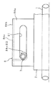
図4は実施の形態2の車体への枢支側部分を拡大した正面図、図5は図4のV−V 線の断面図である。
実施の形態2のステアリング装置は、軸受部材9,9の凸部93,93をピンとする代わりに、支持部91,91に破断用溝94aを有する凸部94,94を突設し、この凸部94,94に係合する係合部82,82としての凹部82a,82aを長孔81,81の一端部両側面に設けたものである。
【0031】
実施の形態2において、軸受部材9,9は合成樹脂製であり、ハウジング2に加わる長手方向への荷重により破断用溝94a部分が剪断されるように構成されている。
【0032】
実施の形態2にあっては、軸受部材9,9の凸部94,94が長孔81,81内で凹部82a,82aに係合しており、軸受部材9,9の取着部材8,8との相対移動が規制されているため、軸受部材9,9の長孔81,81内での相対移動を防ぐことができ、ハウジング2の枢軸部分でのガタ付きをなくすることができる。また、二次衝突の衝撃エネルギによってハウジング2が長手方向へ移動する場合、凸部94,94の破断用溝94a,94aが取着部材8,8の凹部82a,82aにより破断しつつハウジング2が軸受部材9,9及び枢軸3に対して長手方向へ移動し、衝撃エネルギを吸収することができる。
その他の構成及び作用は実施の形態1と同様であるため、同様の部品については同じ符号を付し、その詳細な説明及び作用効果の説明を省略する。
【0033】
実施の形態3
図6は実施の形態3の車体への枢支側部分を拡大した正面図、図7は図6のVII −VII 線の断面図である。
実施の形態3のステアリング装置は、環状板部92,92に凸部93,93を突設する代わりに、筒状の支持部91の外周部に凸部95,95を設け、この凸95,95に係合する係合部82,82としての凸部82b,82bを長孔81,81の一端部両側面に設けたものである。
【0034】
実施の形態3において、軸受部材9,9は合成樹脂製であり、ハウジング2に加わる長手方向への荷重により凸部95,95が変形又は破断するように構成されている。
係合部82,82としての凸部95,95は長孔81,81両側面の途中を内側へ突出させることにより形成されている。
【0035】
実施の形態3にあっては、実施の形態2と同様、軸受部材9,9の凸部95,95が長孔81,81内で凸部82b,82bに係合しており、軸受部材9,9の取着部材8,8との相対移動が規制されているため、軸受部材9,9の長孔81,81内での相対移動を防ぐことができ、ハウジング2の枢軸部分でのガタ付きをなくすることができる。また、二次衝突の衝撃エネルギによってハウジング2が長手方向へ移動する場合、軸受部材9,9の凸部95,95が取着部材8,8の凸部82b,82bにより破断しつつハウジング2が軸受部材9,9及び枢軸3に対して長手方向へ移動し、衝撃エネルギを吸収することができる。
その他の構成及び作用は実施の形態1と同様であるため、同様の部品については同じ符号を付し、その詳細な説明及び作用効果の説明を省略する。
【0036】
実施の形態4
図8は実施の形態4の車体への枢支側部分を拡大した正面図、図9は図8のIX−IX線の断面図である。
実施の形態4のステアリング装置は、枢軸3が嵌入される長孔81,81を有する取着部材8,8を車体Bが有し、ハウジング2との相対移動が不可能な枢軸3を軸受部材9,9を介してハウジング2に支持し、軸受部材9,9の凸部93,93に係合する係合部82,82を取着部材8,8に設け、軸受部材9,9に対してハウジング2を回転可能とし、凸部93,93の破断によりハウジング2を車体B側の取着部材8,8に対して移動させ得るように構成したものである。
【0037】
実施の形態4において、軸受部材9,9は枢軸3を長孔81,81の一端部に相対回転自在に嵌入する環状の支持部91,91を有し取着部材8,8の側面と向き合う環状板部92及び該環状板部92の取着部材8,8との対面部に突設された凸部93,93を有する合成樹脂製の軸受部材9,9が外嵌されており、該軸受部材9,9を介して枢軸3が長孔81,81の長手方向一端部に内嵌されている。支持部91,91は枢軸3を長孔81,81の一端部に相対回転自在に支持している。
ハウジング2には枢軸3が嵌入される貫通孔21a,21aを有する支持板21,21が突設されている。
【0038】
実施の形態4にあっては、実施の形態1と同様、軸受部材9,9の凸部93,93が取着部材8,8の係合部82,82に係合しており、軸受部材9,9の取着部材8,8との相対回転及び相対移動が規制されているため、軸受部材9,9の長孔81,81内での相対移動を防ぐことができ、ハウジング2の枢軸部分でのガタ付きをなくすることができる。また、二次衝突の衝撃エネルギによってハウジング2が長手方向へ移動する場合、軸受部材9,9の凸部93,93が取着部材8,8の係合部82,82により破断しつつハウジング2が軸受部材9,9及び枢軸3とともに長手方向へ移動し、衝撃エネルギを吸収することができる。その他の構成及び作用は実施の形態1と同様であるため、同様の部品については同じ符号を付し、その詳細な説明及び作用効果の説明を省略する。
尚、実施の形態4において、軸受部材9,9をなくし、枢軸3に凸部93,93を設けた構成としてもよい。この場合、ハウジング2は枢軸3に対して回転可能とする。また、実施の形態4は実施の形態2、3の構成を適用してもよい。
【0039】
実施の形態5
図10は実施の形態5の車体への枢支側部分を拡大した正面図、図11は図10のXI−XI線の断面図である。
実施の形態5のステアリング装置は、凸部93,93を有する軸受部材9,9を備える代わりに、枢軸3を長孔81,81の一端面に弾圧する弾圧部83,83を取着部材8,8に設けたものである。
【0040】
実施の形態5において、取着部材8,8は長孔81,81を有しハウジング2の外周面の周方向へ離隔した位置に固着される2つの取着板84a,84aと、該取着板84a,84aの反固着側端を連結する連結板84bとにより略コ字形に形成されている。連結板84bには略コ字形の切り込み84c及び該切り込み84c内の舌片が設けられている。
【0041】
弾圧部83,83は舌片が長孔81,81の一端面に向けて板厚方向内側へ曲げられた曲げ片84dからなる。この曲げ片84dは長孔81,81の一端面と曲げ片84dとの間の距離が枢軸3の外径寸法よりも短くなる位置にかけて曲げられており、この曲げ片84dと長孔81,81の一端面との間に枢軸3を嵌入したとき、該枢軸3に適宜の弾圧を加えることができるように構成されている。この予圧は曲げ片84dの曲げ部から先端までの長さ及び幅寸法により適宜設定することができる。尚、切り込み84c及び舌片は長孔81,81の長手方向中央部に臨む位置に設けられており、舌片が長孔81,81の他端面側から一端面に向けて曲げられている。
【0042】
また、長孔81,81の一端面は湾曲中央部が凹となる非円弧面になっており、断面円形の枢軸3が2点接触するようになっている。斯く構成することにより、長孔81,81が切削加工されることなくプレス成形された場合においても、長孔81,81の一端面と曲げ片84dとにより枢軸3を3点支持することができ、枢軸3を相対回転自在に支持できる。
枢軸3は車体Bに設けられる支持部材の孔に嵌入支持されている。
【0043】
実施の形態5にあっては、枢軸3に加える弾圧により枢軸3を長孔81,81の一端面に弾圧しているため、弾圧部83,83により荷重設定を簡易に行うことができるとともに、枢軸部分にガタ付きが発生するのを防ぐことができる。
その他の構成及び作用は実施の形態1と同様であるため、同様の部品については同じ符号を付し、その詳細な説明及び作用効果の説明を省略する。
【0044】
実施の形態6
図12は実施の形態6の車体への枢支側部分を拡大した正面図である。
実施の形態6のステアリング装置は、実施の形態5のように弾圧部83,83を連結板84bと直交的になる曲げ片84dからなる構成とする代わりに、弾圧部83,83を略J字形に曲げられた曲げ片84eからなる構成としたものである。
【0045】
実施の形態6において、曲げ片84eは長孔81,81の一端面近傍位置から長孔81,81に臨むように略J字形に曲げられており、この曲げ片84eの先端部が枢軸3の周面に接触し、該枢軸3を長孔81,81の一端面に弾圧している。
その他の構成及び作用は実施の形態1、5と同様であるため、同様の部品については同じ符号を付し、その詳細な説明及び作用効果の説明を省略する。
【0046】
実施の形態7
図13は実施の形態7の車体への枢支側部分を拡大した正面図である。
実施の形態7のステアリング装置は、実施の形態5のように曲げ片84dが長孔81,81の他端面側から一端面に向けて曲げられている構成とする代わりに、曲げ片84fが長孔81,81の一端面側から一端面と向き合う位置にかけて曲げられている構成としたものであり、この曲げ片84fの先端部が枢軸3の周面に接触し、該枢軸3を長孔81,81の一端面に弾圧している。
その他の構成及び作用は実施の形態1、5と同様であるため、同様の部品については同じ符号を付し、その詳細な説明及び作用効果の説明を省略する。
【0047】
尚、以上説明した実施の形態1乃至3では長孔81,81を有する取着部材8,8をハウジング2に固着した構成としたが、その他、ハウジング2の一部を膨出させ、該膨出部分を長孔81,81を有する取着部材8,8としてもよい。
また、以上説明した実施の形態では筒状の支持部91及び鍔部92を有する軸受部材9を用いたが、その他、この軸受部材9は枢軸3が嵌入される孔を有する円板状としてもよく、軸受部材9の形状は特に制限されない。
【0048】
【発明の効果】
以上詳述したように第1発明によれば、枢軸部分にガタ付きが発生しないように枢軸を支持することができ、しかも、支持部と関係なく荷重を設定することができ、この荷重設定を簡易に行うことができる。
【0049】
第2発明によれば、支持部及び凸部を一体に成形することが可能であり、しかも、組込作業性を向上できる。
【図面の簡単な説明】
【図1】本発明に係るステアリング装置の実施の形態1の構成を示す正面図である。
【図2】実施の形態1の車体への枢支側部分を拡大した正面図である。
【図3】図2のIII−III線の断面図である。
【図4】実施の形態2の車体への枢支側部分を拡大した正面図である。
【図5】図4のV −V 線の断面図である。
【図6】実施の形態3の車体への枢支側部分を拡大した正面図である。
【図7】図6のVII −VII 線の断面図である。
【図8】実施の形態4の車体への枢支側部分を拡大した正面図である。
【図9】図8のIX−IX線の断面図である。
【図10】実施の形態5の車体への枢支側部分を拡大した正面図である。
【図11】図10のXI−XI線の断面図である。
【図12】実施の形態6の車体への枢支側部分を拡大した正面図である。
【図13】実施の形態7の車体への枢支側部分を拡大した正面図である。
【符号の説明】
1 操舵軸
2 ハウジング
3 枢軸
8 取着部材
81 長孔
82 係合部
83 弾圧部
84d,84e,84f 曲げ片
9 軸受部材
91 支持部
93 凸部[0001]
BACKGROUND OF THE INVENTION
The present invention relates to a steering device in which one end of a housing that supports a steering shaft is pivotally supported on a vehicle body via a pivot.
[0002]
[Prior art]
As a steering apparatus for an automobile, for example, a tilt type having a tilt mechanism that can adjust a vertical position of a steering wheel with respect to a driver's seat is known.
[0003]
The tilt type steering device is separated in a direction crossing the longitudinal direction of the housing at the end opposite to the longitudinal steering wheel side of the cylindrical housing that rotatably accommodates and supports the steering shaft coupled to the steering wheel. And a pivot shaft fitted in a long hole formed in each attachment plate so as to be rotatable relative to each other. The attachment tool and the tilt adjustment are provided at the center in the longitudinal direction of the housing. An adjustment lever is provided. Further, the long hole has a large diameter hole portion corresponding to the pivot shaft at one end, and a narrow width portion narrower than the diameter dimension of the pivot shaft from the large diameter hole portion to the other end portion. A pivot is inserted into the portion (see, for example, Patent Document 1).
[0004]
Two support plates that face the mounting plate protrude from the vehicle body, and one end of the housing can be swung to the vehicle body by inserting the pivot into a through hole formed in the support plate. Pivot.
When the load in the longitudinal direction is applied to the housing due to the impact energy of the secondary collision, the pivot shaft squeezes the narrow portion of the long hole, and absorbs the impact energy while plastically deforming the narrow portion. .
[0005]
Further, as a tilt type steering device, instead of a long hole having a large-diameter hole portion and a narrow-width portion as in
[0006]
In this steering device, the peripheral surface of the pivot contacts the convex piece, the movement of the convex piece and one end surface of the elongated hole in the elongated hole of the pivot is restricted, and the housing is longitudinally moved by the impact energy of the secondary collision. When the load is applied, the impact energy is absorbed while the convex piece is plastically deformed by the pivot.
[0007]
[Patent Document 1]
Japanese Utility Model Publication No. 62-23771 [Patent Document 2]
Japanese Patent Laid-Open No. 2002-59853
[Problems to be solved by the invention]
However, in the configuration in which the long hole has a large-diameter hole portion and a narrow-width portion as in
Further, in
[0009]
The present invention has been made in view of such circumstances, and an object of the present invention is to provide a steering device that can easily prevent rattling of the pivot portion and set an appropriate load.
[0010]
[Means for Solving the Problems]
In the steering device according to the first aspect of the present invention, one end of the housing that accommodates and supports the steering shaft is swingably attached to the support member on the vehicle body side via an attachment member having a pivot and a long hole into which the pivot is inserted. In the steering device to be worn, the attachment member has an engagement portion at a position separated in the width direction of the long hole, and engages with the hole fitted to the pivot and the engagement portion, and the cross-sectional fracture when a load in the longitudinal direction applied to the housing has a convex portion for relatively moving the said pivot and the securing member, the convex portion is broken disposed between the attachment member and the support member when, characterized by the Turkey includes a bearing member which can be moved in the pivot integrally.
[0011]
In the first invention, since the pivot for attaching the housing to the vehicle body so as to be swingable is supported by the support portion so as to be relatively rotatable, the pivot is supported so that rattling does not occur in the pivot portion. Moreover, since the load can be set by the convex portion provided at a position separated from the support portion, the load can be set regardless of the support portion, and the load setting can be easily performed.
[0012]
The steering apparatus according to a second aspect is characterized in that the bearing member is made of synthetic resin .
[0013]
In the second invention, since the bearing member fitted on the pivot has the support part and the convex part, the support part and the convex part can be formed integrally, and the bearing member is mounted on the pivot. Since a support part and a convex part can be arrange | positioned by fitting, assembly workability | operativity can be improved.
[0018]
DETAILED DESCRIPTION OF THE INVENTION
Hereinafter, the present invention will be described in detail with reference to the drawings illustrating embodiments thereof.
FIG. 1 is a front view showing the configuration of the steering device according to the first embodiment, FIG. 2 is an enlarged front view of a pivot side portion of the vehicle body of the first embodiment, and FIG. 3 is a cross-sectional view taken along the line III-III in FIG. FIG.
[0019]
The tilt type steering device includes a
[0020]
The
At one end of the
[0021]
At both ends of the
[0022]
The
[0023]
The engaging
[0024]
The
[0025]
The
[0026]
The vehicle body B that pivotally supports the tilt type steering device configured as described above is provided with through holes 11a and 11a that are separated by a distance corresponding to the distance between the
[0027]
In the steering device attached to the vehicle body B, the
[0028]
When the tilt adjustment is performed, the
[0029]
Further, when the
In the first embodiment, the
[0030]
FIG. 4 is an enlarged front view of the pivot side portion of the vehicle body of the second embodiment, and FIG. 5 is a cross-sectional view taken along the line V-V in FIG.
In the steering device of the second embodiment, instead of using the
[0031]
In the second embodiment, the bearing
[0032]
In the second embodiment, the
Since other configurations and operations are the same as those of the first embodiment, the same components are denoted by the same reference numerals, and detailed description thereof and description of operations and effects are omitted.
[0033]
FIG. 6 is an enlarged front view of the pivot side portion of the vehicle body of
In the steering device of the third embodiment, instead of projecting the
[0034]
In the third embodiment, the bearing
The
[0035]
In the third embodiment, similarly to the second embodiment, the
Since other configurations and operations are the same as those of the first embodiment, the same components are denoted by the same reference numerals, and detailed description thereof and description of operations and effects are omitted.
[0036]
FIG. 8 is an enlarged front view of the pivot side portion of the vehicle body of the fourth embodiment, and FIG. 9 is a sectional view taken along the line IX-IX in FIG.
In the steering device according to the fourth embodiment, the vehicle body B has
[0037]
In the fourth embodiment, the bearing
[0038]
In the fourth embodiment, as in the first embodiment, the
In the fourth embodiment, the bearing
[0039]
FIG. 10 is an enlarged front view of the pivot side portion of the fifth embodiment, and FIG. 11 is a cross-sectional view taken along the line XI-XI in FIG.
The steering apparatus according to the fifth embodiment attaches the
[0040]
In the fifth embodiment, the
[0041]
The
[0042]
Further, one end surface of each of the
The
[0043]
In the fifth embodiment, since the
Since other configurations and operations are the same as those of the first embodiment, the same components are denoted by the same reference numerals, and detailed description thereof and description of operations and effects are omitted.
[0044]
FIG. 12 is an enlarged front view of a pivot side portion of the vehicle body according to the sixth embodiment.
In the steering device of the sixth embodiment, instead of the
[0045]
In the sixth embodiment, the bent piece 84e is bent in a substantially J shape so as to face the
Since other configurations and operations are the same as those of the first and fifth embodiments, the same components are denoted by the same reference numerals, and detailed description thereof and description of the operations and effects are omitted.
[0046]
FIG. 13 is an enlarged front view of a pivot side portion to the vehicle body of the seventh embodiment.
In the steering device of the seventh embodiment, the bent piece 84f is long instead of the configuration in which the
Since other configurations and operations are the same as those in the first and fifth embodiments, the same components are denoted by the same reference numerals, and detailed description thereof and description of the operations and effects are omitted.
[0047]
In the first to third embodiments described above, the
In the embodiment described above, the bearing
[0048]
【The invention's effect】
As described above in detail, according to the first aspect of the invention, the pivot can be supported so that the pivot portion does not rattle, and the load can be set regardless of the support portion. It can be done easily.
[0049]
According to the second aspect of the present invention, the support portion and the convex portion can be formed integrally, and the assembly workability can be improved.
[Brief description of the drawings]
FIG. 1 is a front view showing a configuration of a steering device according to a first embodiment of the present invention.
FIG. 2 is an enlarged front view of a pivot side portion to the vehicle body of the first embodiment.
3 is a cross-sectional view taken along line III-III in FIG.
4 is an enlarged front view of a pivot side portion of a vehicle body according to a second embodiment. FIG.
5 is a cross-sectional view taken along the line V-V in FIG. 4;
FIG. 6 is an enlarged front view of a pivot side portion to a vehicle body according to a third embodiment.
7 is a cross-sectional view taken along line VII-VII in FIG.
FIG. 8 is an enlarged front view of a pivot side portion of a vehicle body according to a fourth embodiment.
9 is a cross-sectional view taken along line IX-IX in FIG.
FIG. 10 is an enlarged front view of a pivot side portion to a vehicle body according to a fifth embodiment.
11 is a cross-sectional view taken along line XI-XI in FIG.
FIG. 12 is an enlarged front view of a pivot side portion to a vehicle body of a sixth embodiment.
FIG. 13 is an enlarged front view of a pivot side portion to a vehicle body according to a seventh embodiment.
[Explanation of symbols]
DESCRIPTION OF
Claims (2)
前記取着部材は、前記長孔の幅方向へ離隔した位置に係合部を有し、
前記枢軸に外嵌される孔及び前記係合部に係合し、前記ハウジングに長手方向への荷重が加わったとき破断して前記枢軸と取着部材とを相対移動させる凸部を有し、前記取着部材及び支持部材間に配されて前記凸部が破断したとき、前記枢軸と一体に移動することが可能な軸受部材を備えることを特徴とするステアリング装置。In a steering apparatus in which one end portion of a housing that accommodates and supports a steering shaft is swingably attached to a support member on the vehicle body side via an attachment member having a pivot and a long hole into which the pivot is inserted.
The attachment member has an engaging portion at a position separated in the width direction of the long hole,
The engages hole and the engaging portion is fitted to the pivot, has a convex portion for relatively moving the said pivot and the attachment member to the cross-sectional fracture when a load is applied in the longitudinal direction in the housing A steering apparatus comprising: a bearing member that is disposed between the attachment member and the support member and is capable of moving integrally with the pivot when the convex portion is broken .
Priority Applications (1)
| Application Number | Priority Date | Filing Date | Title |
|---|---|---|---|
| JP2003203994A JP4158635B2 (en) | 2003-07-30 | 2003-07-30 | Steering device |
Applications Claiming Priority (1)
| Application Number | Priority Date | Filing Date | Title |
|---|---|---|---|
| JP2003203994A JP4158635B2 (en) | 2003-07-30 | 2003-07-30 | Steering device |
Publications (2)
| Publication Number | Publication Date |
|---|---|
| JP2005047319A JP2005047319A (en) | 2005-02-24 |
| JP4158635B2 true JP4158635B2 (en) | 2008-10-01 |
Family
ID=34263163
Family Applications (1)
| Application Number | Title | Priority Date | Filing Date |
|---|---|---|---|
| JP2003203994A Expired - Fee Related JP4158635B2 (en) | 2003-07-30 | 2003-07-30 | Steering device |
Country Status (1)
| Country | Link |
|---|---|
| JP (1) | JP4158635B2 (en) |
Families Citing this family (5)
| Publication number | Priority date | Publication date | Assignee | Title |
|---|---|---|---|---|
| JP4795993B2 (en) * | 2007-02-28 | 2011-10-19 | 富士機工株式会社 | Steering column device |
| JP5499995B2 (en) * | 2010-08-26 | 2014-05-21 | 日本精工株式会社 | Shock absorbing steering device with electric power steering device |
| JP2012180039A (en) * | 2011-03-02 | 2012-09-20 | Yamada Seisakusho Co Ltd | Steering device |
| JP2012180038A (en) * | 2011-03-02 | 2012-09-20 | Yamada Seisakusho Co Ltd | Steering device |
| JP5935495B2 (en) * | 2012-05-10 | 2016-06-15 | 株式会社ジェイテクト | Steering column shock absorbing mechanism and steering column device having the same |
-
2003
- 2003-07-30 JP JP2003203994A patent/JP4158635B2/en not_active Expired - Fee Related
Also Published As
| Publication number | Publication date |
|---|---|
| JP2005047319A (en) | 2005-02-24 |
Similar Documents
| Publication | Publication Date | Title |
|---|---|---|
| JPS607260Y2 (en) | Car steering wheel safety device | |
| US7328631B2 (en) | Vehicular steering apparatus | |
| WO2015190300A1 (en) | Steering device | |
| JP5626346B2 (en) | Automotive steering device | |
| JP6620880B2 (en) | Steering device | |
| US10081384B2 (en) | Steering system | |
| JP6241652B2 (en) | Steering device | |
| JP4158635B2 (en) | Steering device | |
| JP4561388B2 (en) | Steering device | |
| US20050066760A1 (en) | Column shifter with impact absorbing structure | |
| JP3856610B2 (en) | Steering device | |
| JP2005119369A (en) | Steering device | |
| JP2019123464A (en) | Steering column device | |
| JP2001233223A (en) | Steering device and fitting thereof | |
| JP2006076515A (en) | Wire fixing structure | |
| JP6198042B2 (en) | Steering device | |
| JP2019089557A (en) | Steering device | |
| JP2019116274A (en) | Steering device | |
| JP2020093652A (en) | Shock absorbing type steering device | |
| JP3688174B2 (en) | Steering device and fitting used therefor | |
| JP2006062497A (en) | Shift lever device | |
| JP2001158364A (en) | Telescopic shaft | |
| JP3719913B2 (en) | Steering device and fitting used therefor | |
| JP6150335B2 (en) | Steering device | |
| WO2023038013A1 (en) | Steering column device |
Legal Events
| Date | Code | Title | Description |
|---|---|---|---|
| A621 | Written request for application examination |
Free format text: JAPANESE INTERMEDIATE CODE: A621 Effective date: 20060627 |
|
| A977 | Report on retrieval |
Free format text: JAPANESE INTERMEDIATE CODE: A971007 Effective date: 20070914 |
|
| A131 | Notification of reasons for refusal |
Free format text: JAPANESE INTERMEDIATE CODE: A131 Effective date: 20071016 |
|
| A521 | Written amendment |
Free format text: JAPANESE INTERMEDIATE CODE: A523 Effective date: 20071217 |
|
| TRDD | Decision of grant or rejection written | ||
| A01 | Written decision to grant a patent or to grant a registration (utility model) |
Free format text: JAPANESE INTERMEDIATE CODE: A01 Effective date: 20080624 |
|
| A01 | Written decision to grant a patent or to grant a registration (utility model) |
Free format text: JAPANESE INTERMEDIATE CODE: A01 |
|
| A61 | First payment of annual fees (during grant procedure) |
Free format text: JAPANESE INTERMEDIATE CODE: A61 Effective date: 20080707 |
|
| R150 | Certificate of patent or registration of utility model |
Ref document number: 4158635 Country of ref document: JP Free format text: JAPANESE INTERMEDIATE CODE: R150 Free format text: JAPANESE INTERMEDIATE CODE: R150 |
|
| FPAY | Renewal fee payment (event date is renewal date of database) |
Free format text: PAYMENT UNTIL: 20110725 Year of fee payment: 3 |
|
| FPAY | Renewal fee payment (event date is renewal date of database) |
Free format text: PAYMENT UNTIL: 20120725 Year of fee payment: 4 |
|
| FPAY | Renewal fee payment (event date is renewal date of database) |
Free format text: PAYMENT UNTIL: 20120725 Year of fee payment: 4 |
|
| FPAY | Renewal fee payment (event date is renewal date of database) |
Free format text: PAYMENT UNTIL: 20130725 Year of fee payment: 5 |
|
| LAPS | Cancellation because of no payment of annual fees |