JP4154016B2 - Iontophoresis device and assembly method thereof - Google Patents
Iontophoresis device and assembly method thereof Download PDFInfo
- Publication number
- JP4154016B2 JP4154016B2 JP36864897A JP36864897A JP4154016B2 JP 4154016 B2 JP4154016 B2 JP 4154016B2 JP 36864897 A JP36864897 A JP 36864897A JP 36864897 A JP36864897 A JP 36864897A JP 4154016 B2 JP4154016 B2 JP 4154016B2
- Authority
- JP
- Japan
- Prior art keywords
- drug
- electrode
- alignment
- iontophoresis device
- unit
- Prior art date
- Legal status (The legal status is an assumption and is not a legal conclusion. Google has not performed a legal analysis and makes no representation as to the accuracy of the status listed.)
- Expired - Fee Related
Links
- 238000000034 method Methods 0.000 title claims description 62
- 239000003814 drug Substances 0.000 claims description 289
- 229940079593 drug Drugs 0.000 claims description 288
- 230000005540 biological transmission Effects 0.000 claims description 57
- 238000004090 dissolution Methods 0.000 claims description 21
- 239000003937 drug carrier Substances 0.000 claims description 8
- 238000004806 packaging method and process Methods 0.000 claims description 8
- 241001166661 Thelasis Species 0.000 claims 1
- 239000010410 layer Substances 0.000 description 59
- 238000010586 diagram Methods 0.000 description 28
- XLYOFNOQVPJJNP-UHFFFAOYSA-N water Substances O XLYOFNOQVPJJNP-UHFFFAOYSA-N 0.000 description 28
- -1 polyethylene terephthalate Polymers 0.000 description 23
- 239000000463 material Substances 0.000 description 22
- 238000007639 printing Methods 0.000 description 20
- 230000008569 process Effects 0.000 description 18
- 238000003860 storage Methods 0.000 description 16
- 239000002313 adhesive film Substances 0.000 description 13
- 230000000052 comparative effect Effects 0.000 description 11
- 239000000243 solution Substances 0.000 description 11
- 239000012790 adhesive layer Substances 0.000 description 10
- BBBFJLBPOGFECG-VJVYQDLKSA-N calcitonin Chemical compound N([C@H](C(=O)N[C@@H](CC(C)C)C(=O)NCC(=O)N[C@@H](CCCCN)C(=O)N[C@@H](CC(C)C)C(=O)N[C@@H](CO)C(=O)N[C@@H](CCC(N)=O)C(=O)N[C@@H](CCC(O)=O)C(=O)N[C@@H](CC(C)C)C(=O)N[C@@H](CC=1NC=NC=1)C(=O)N[C@@H](CCCCN)C(=O)N[C@@H](CC(C)C)C(=O)N[C@@H](CCC(N)=O)C(=O)N[C@@H]([C@@H](C)O)C(=O)N[C@@H](CC=1C=CC(O)=CC=1)C(=O)N1[C@@H](CCC1)C(=O)N[C@@H](CCCNC(N)=N)C(=O)N[C@@H]([C@@H](C)O)C(=O)N[C@@H](CC(N)=O)C(=O)N[C@@H]([C@@H](C)O)C(=O)NCC(=O)N[C@@H](CO)C(=O)NCC(=O)N[C@@H]([C@@H](C)O)C(=O)N1[C@@H](CCC1)C(N)=O)C(C)C)C(=O)[C@@H]1CSSC[C@H](N)C(=O)N[C@@H](CO)C(=O)N[C@@H](CC(N)=O)C(=O)N[C@@H](CC(C)C)C(=O)N[C@@H](CO)C(=O)N[C@@H]([C@@H](C)O)C(=O)N1 BBBFJLBPOGFECG-VJVYQDLKSA-N 0.000 description 10
- QTBSBXVTEAMEQO-UHFFFAOYSA-N Acetic acid Chemical compound CC(O)=O QTBSBXVTEAMEQO-UHFFFAOYSA-N 0.000 description 9
- 229920001577 copolymer Polymers 0.000 description 9
- 230000007774 longterm Effects 0.000 description 9
- 230000002093 peripheral effect Effects 0.000 description 9
- NBIIXXVUZAFLBC-UHFFFAOYSA-N Phosphoric acid Chemical compound OP(O)(O)=O NBIIXXVUZAFLBC-UHFFFAOYSA-N 0.000 description 8
- 239000004743 Polypropylene Substances 0.000 description 8
- 238000010521 absorption reaction Methods 0.000 description 8
- 229910052782 aluminium Inorganic materials 0.000 description 8
- XAGFODPZIPBFFR-UHFFFAOYSA-N aluminium Chemical compound [Al] XAGFODPZIPBFFR-UHFFFAOYSA-N 0.000 description 8
- 239000011248 coating agent Substances 0.000 description 8
- 238000000576 coating method Methods 0.000 description 8
- 229920001155 polypropylene Polymers 0.000 description 8
- 108090000765 processed proteins & peptides Proteins 0.000 description 8
- 239000000853 adhesive Substances 0.000 description 7
- 230000001070 adhesive effect Effects 0.000 description 7
- 210000004369 blood Anatomy 0.000 description 7
- 239000008280 blood Substances 0.000 description 7
- 239000000499 gel Substances 0.000 description 7
- FAPWRFPIFSIZLT-UHFFFAOYSA-M Sodium chloride Chemical compound [Na+].[Cl-] FAPWRFPIFSIZLT-UHFFFAOYSA-M 0.000 description 6
- 229960003773 calcitonin (salmon synthetic) Drugs 0.000 description 6
- KRKNYBCHXYNGOX-UHFFFAOYSA-N citric acid Chemical compound OC(=O)CC(O)(C(O)=O)CC(O)=O KRKNYBCHXYNGOX-UHFFFAOYSA-N 0.000 description 6
- 230000008878 coupling Effects 0.000 description 6
- 238000010168 coupling process Methods 0.000 description 6
- 238000005859 coupling reaction Methods 0.000 description 6
- 238000003780 insertion Methods 0.000 description 6
- 230000037431 insertion Effects 0.000 description 6
- 239000012528 membrane Substances 0.000 description 6
- 238000002360 preparation method Methods 0.000 description 6
- 102000004196 processed proteins & peptides Human genes 0.000 description 6
- 108010068072 salmon calcitonin Proteins 0.000 description 6
- 238000001179 sorption measurement Methods 0.000 description 6
- 230000004913 activation Effects 0.000 description 5
- 239000003792 electrolyte Substances 0.000 description 5
- 230000006870 function Effects 0.000 description 5
- 210000004379 membrane Anatomy 0.000 description 5
- 239000004745 nonwoven fabric Substances 0.000 description 5
- 239000012466 permeate Substances 0.000 description 5
- 230000000144 pharmacologic effect Effects 0.000 description 5
- 229920000642 polymer Polymers 0.000 description 5
- 210000002966 serum Anatomy 0.000 description 5
- 108091003079 Bovine Serum Albumin Proteins 0.000 description 4
- 102000055006 Calcitonin Human genes 0.000 description 4
- 108060001064 Calcitonin Proteins 0.000 description 4
- WCUXLLCKKVVCTQ-UHFFFAOYSA-M Potassium chloride Chemical compound [Cl-].[K+] WCUXLLCKKVVCTQ-UHFFFAOYSA-M 0.000 description 4
- BQCADISMDOOEFD-UHFFFAOYSA-N Silver Chemical compound [Ag] BQCADISMDOOEFD-UHFFFAOYSA-N 0.000 description 4
- 229910021607 Silver chloride Inorganic materials 0.000 description 4
- CDBYLPFSWZWCQE-UHFFFAOYSA-L Sodium Carbonate Chemical compound [Na+].[Na+].[O-]C([O-])=O CDBYLPFSWZWCQE-UHFFFAOYSA-L 0.000 description 4
- NIXOWILDQLNWCW-UHFFFAOYSA-N acrylic acid group Chemical group C(C=C)(=O)O NIXOWILDQLNWCW-UHFFFAOYSA-N 0.000 description 4
- 239000013543 active substance Substances 0.000 description 4
- 229910000147 aluminium phosphate Inorganic materials 0.000 description 4
- 229940098773 bovine serum albumin Drugs 0.000 description 4
- 229960004015 calcitonin Drugs 0.000 description 4
- 239000002274 desiccant Substances 0.000 description 4
- 230000000694 effects Effects 0.000 description 4
- 239000007772 electrode material Substances 0.000 description 4
- 239000006260 foam Substances 0.000 description 4
- 239000000017 hydrogel Substances 0.000 description 4
- NOESYZHRGYRDHS-UHFFFAOYSA-N insulin Chemical compound N1C(=O)C(NC(=O)C(CCC(N)=O)NC(=O)C(CCC(O)=O)NC(=O)C(C(C)C)NC(=O)C(NC(=O)CN)C(C)CC)CSSCC(C(NC(CO)C(=O)NC(CC(C)C)C(=O)NC(CC=2C=CC(O)=CC=2)C(=O)NC(CCC(N)=O)C(=O)NC(CC(C)C)C(=O)NC(CCC(O)=O)C(=O)NC(CC(N)=O)C(=O)NC(CC=2C=CC(O)=CC=2)C(=O)NC(CSSCC(NC(=O)C(C(C)C)NC(=O)C(CC(C)C)NC(=O)C(CC=2C=CC(O)=CC=2)NC(=O)C(CC(C)C)NC(=O)C(C)NC(=O)C(CCC(O)=O)NC(=O)C(C(C)C)NC(=O)C(CC(C)C)NC(=O)C(CC=2NC=NC=2)NC(=O)C(CO)NC(=O)CNC2=O)C(=O)NCC(=O)NC(CCC(O)=O)C(=O)NC(CCCNC(N)=N)C(=O)NCC(=O)NC(CC=3C=CC=CC=3)C(=O)NC(CC=3C=CC=CC=3)C(=O)NC(CC=3C=CC(O)=CC=3)C(=O)NC(C(C)O)C(=O)N3C(CCC3)C(=O)NC(CCCCN)C(=O)NC(C)C(O)=O)C(=O)NC(CC(N)=O)C(O)=O)=O)NC(=O)C(C(C)CC)NC(=O)C(CO)NC(=O)C(C(C)O)NC(=O)C1CSSCC2NC(=O)C(CC(C)C)NC(=O)C(NC(=O)C(CCC(N)=O)NC(=O)C(CC(N)=O)NC(=O)C(NC(=O)C(N)CC=1C=CC=CC=1)C(C)C)CC1=CN=CN1 NOESYZHRGYRDHS-UHFFFAOYSA-N 0.000 description 4
- 229920003303 ion-exchange polymer Polymers 0.000 description 4
- 210000004400 mucous membrane Anatomy 0.000 description 4
- 239000000123 paper Substances 0.000 description 4
- 239000002985 plastic film Substances 0.000 description 4
- 229920006255 plastic film Polymers 0.000 description 4
- 229910052709 silver Inorganic materials 0.000 description 4
- 239000004332 silver Substances 0.000 description 4
- HKZLPVFGJNLROG-UHFFFAOYSA-M silver monochloride Chemical compound [Cl-].[Ag+] HKZLPVFGJNLROG-UHFFFAOYSA-M 0.000 description 4
- 239000001509 sodium citrate Substances 0.000 description 4
- NLJMYIDDQXHKNR-UHFFFAOYSA-K sodium citrate Chemical compound O.O.[Na+].[Na+].[Na+].[O-]C(=O)CC(O)(CC([O-])=O)C([O-])=O NLJMYIDDQXHKNR-UHFFFAOYSA-K 0.000 description 4
- 239000000126 substance Substances 0.000 description 4
- 102400000739 Corticotropin Human genes 0.000 description 3
- 101800000414 Corticotropin Proteins 0.000 description 3
- LYCAIKOWRPUZTN-UHFFFAOYSA-N Ethylene glycol Chemical compound OCCO LYCAIKOWRPUZTN-UHFFFAOYSA-N 0.000 description 3
- 239000004698 Polyethylene Substances 0.000 description 3
- 239000004809 Teflon Substances 0.000 description 3
- 229920006362 Teflon® Polymers 0.000 description 3
- 239000002253 acid Substances 0.000 description 3
- 239000002390 adhesive tape Substances 0.000 description 3
- IDLFZVILOHSSID-OVLDLUHVSA-N corticotropin Chemical compound C([C@@H](C(=O)N[C@@H](CO)C(=O)N[C@@H](CCSC)C(=O)N[C@@H](CCC(O)=O)C(=O)N[C@@H](CC=1NC=NC=1)C(=O)N[C@@H](CC=1C=CC=CC=1)C(=O)N[C@@H](CCCNC(N)=N)C(=O)N[C@@H](CC=1C2=CC=CC=C2NC=1)C(=O)NCC(=O)N[C@@H](CCCCN)C(=O)N1[C@@H](CCC1)C(=O)N[C@@H](C(C)C)C(=O)NCC(=O)N[C@@H](CCCCN)C(=O)N[C@@H](CCCCN)C(=O)N[C@@H](CCCNC(N)=N)C(=O)N[C@@H](CCCNC(N)=N)C(=O)N1[C@@H](CCC1)C(=O)N[C@@H](C(C)C)C(=O)N[C@@H](CCCCN)C(=O)N[C@@H](C(C)C)C(=O)N[C@@H](CC=1C=CC(O)=CC=1)C(=O)N1[C@@H](CCC1)C(=O)N[C@@H](CC(N)=O)C(=O)NCC(=O)N[C@@H](C)C(=O)N[C@@H](CCC(O)=O)C(=O)N[C@@H](CC(O)=O)C(=O)N[C@@H](CCC(O)=O)C(=O)N[C@@H](CO)C(=O)N[C@@H](C)C(=O)N[C@@H](CCC(O)=O)C(=O)N[C@@H](C)C(=O)N[C@@H](CC=1C=CC=CC=1)C(=O)N1[C@@H](CCC1)C(=O)N[C@@H](CC(C)C)C(=O)N[C@@H](CCC(O)=O)C(=O)N[C@@H](CC=1C=CC=CC=1)C(O)=O)NC(=O)[C@@H](N)CO)C1=CC=C(O)C=C1 IDLFZVILOHSSID-OVLDLUHVSA-N 0.000 description 3
- 229960000258 corticotropin Drugs 0.000 description 3
- 238000010790 dilution Methods 0.000 description 3
- 239000012895 dilution Substances 0.000 description 3
- 239000011888 foil Substances 0.000 description 3
- 229940088597 hormone Drugs 0.000 description 3
- 239000005556 hormone Substances 0.000 description 3
- 150000002500 ions Chemical class 0.000 description 3
- 229910052751 metal Inorganic materials 0.000 description 3
- 239000002184 metal Substances 0.000 description 3
- BASFCYQUMIYNBI-UHFFFAOYSA-N platinum Chemical compound [Pt] BASFCYQUMIYNBI-UHFFFAOYSA-N 0.000 description 3
- 229920000728 polyester Polymers 0.000 description 3
- 229920000573 polyethylene Polymers 0.000 description 3
- 229920000098 polyolefin Polymers 0.000 description 3
- 229920002635 polyurethane Polymers 0.000 description 3
- 239000004814 polyurethane Substances 0.000 description 3
- 230000001681 protective effect Effects 0.000 description 3
- 108090000623 proteins and genes Proteins 0.000 description 3
- 238000007789 sealing Methods 0.000 description 3
- 239000011780 sodium chloride Substances 0.000 description 3
- 229920003002 synthetic resin Polymers 0.000 description 3
- 229920003169 water-soluble polymer Polymers 0.000 description 3
- WWYNJERNGUHSAO-XUDSTZEESA-N (+)-Norgestrel Chemical compound O=C1CC[C@@H]2[C@H]3CC[C@](CC)([C@](CC4)(O)C#C)[C@@H]4[C@@H]3CCC2=C1 WWYNJERNGUHSAO-XUDSTZEESA-N 0.000 description 2
- KWGRBVOPPLSCSI-WPRPVWTQSA-N (-)-ephedrine Chemical compound CN[C@@H](C)[C@H](O)C1=CC=CC=C1 KWGRBVOPPLSCSI-WPRPVWTQSA-N 0.000 description 2
- 239000000275 Adrenocorticotropic Hormone Substances 0.000 description 2
- 229920001817 Agar Polymers 0.000 description 2
- 108010064733 Angiotensins Proteins 0.000 description 2
- 102000015427 Angiotensins Human genes 0.000 description 2
- 241000972773 Aulopiformes Species 0.000 description 2
- SOGAXMICEFXMKE-UHFFFAOYSA-N Butylmethacrylate Chemical compound CCCCOC(=O)C(C)=C SOGAXMICEFXMKE-UHFFFAOYSA-N 0.000 description 2
- OKTJSMMVPCPJKN-UHFFFAOYSA-N Carbon Chemical compound [C] OKTJSMMVPCPJKN-UHFFFAOYSA-N 0.000 description 2
- 108700012941 GNRH1 Proteins 0.000 description 2
- 102400000321 Glucagon Human genes 0.000 description 2
- 108060003199 Glucagon Proteins 0.000 description 2
- PEDCQBHIVMGVHV-UHFFFAOYSA-N Glycerine Chemical compound OCC(O)CO PEDCQBHIVMGVHV-UHFFFAOYSA-N 0.000 description 2
- 239000000579 Gonadotropin-Releasing Hormone Substances 0.000 description 2
- 102100039619 Granulocyte colony-stimulating factor Human genes 0.000 description 2
- 108010051696 Growth Hormone Proteins 0.000 description 2
- 239000000095 Growth Hormone-Releasing Hormone Substances 0.000 description 2
- 108090001061 Insulin Proteins 0.000 description 2
- 102000004877 Insulin Human genes 0.000 description 2
- XEEYBQQBJWHFJM-UHFFFAOYSA-N Iron Chemical compound [Fe] XEEYBQQBJWHFJM-UHFFFAOYSA-N 0.000 description 2
- 102000009151 Luteinizing Hormone Human genes 0.000 description 2
- 108010073521 Luteinizing Hormone Proteins 0.000 description 2
- BAPJBEWLBFYGME-UHFFFAOYSA-N Methyl acrylate Chemical compound COC(=O)C=C BAPJBEWLBFYGME-UHFFFAOYSA-N 0.000 description 2
- 108010025020 Nerve Growth Factor Proteins 0.000 description 2
- 102000015336 Nerve Growth Factor Human genes 0.000 description 2
- 102400000050 Oxytocin Human genes 0.000 description 2
- 101800000989 Oxytocin Proteins 0.000 description 2
- XNOPRXBHLZRZKH-UHFFFAOYSA-N Oxytocin Natural products N1C(=O)C(N)CSSCC(C(=O)N2C(CCC2)C(=O)NC(CC(C)C)C(=O)NCC(N)=O)NC(=O)C(CC(N)=O)NC(=O)C(CCC(N)=O)NC(=O)C(C(C)CC)NC(=O)C1CC1=CC=C(O)C=C1 XNOPRXBHLZRZKH-UHFFFAOYSA-N 0.000 description 2
- 108090000445 Parathyroid hormone Proteins 0.000 description 2
- 239000004952 Polyamide Substances 0.000 description 2
- 239000005062 Polybutadiene Substances 0.000 description 2
- 229920002367 Polyisobutene Polymers 0.000 description 2
- 239000004793 Polystyrene Substances 0.000 description 2
- 239000004372 Polyvinyl alcohol Substances 0.000 description 2
- 239000004820 Pressure-sensitive adhesive Substances 0.000 description 2
- RJKFOVLPORLFTN-LEKSSAKUSA-N Progesterone Chemical compound C1CC2=CC(=O)CC[C@]2(C)[C@@H]2[C@@H]1[C@@H]1CC[C@H](C(=O)C)[C@@]1(C)CC2 RJKFOVLPORLFTN-LEKSSAKUSA-N 0.000 description 2
- VMHLLURERBWHNL-UHFFFAOYSA-M Sodium acetate Chemical compound [Na+].CC([O-])=O VMHLLURERBWHNL-UHFFFAOYSA-M 0.000 description 2
- 229920002125 Sokalan® Polymers 0.000 description 2
- 102100022831 Somatoliberin Human genes 0.000 description 2
- 101710142969 Somatoliberin Proteins 0.000 description 2
- 102100038803 Somatotropin Human genes 0.000 description 2
- MUMGGOZAMZWBJJ-DYKIIFRCSA-N Testostosterone Chemical compound O=C1CC[C@]2(C)[C@H]3CC[C@](C)([C@H](CC4)O)[C@@H]4[C@@H]3CCC2=C1 MUMGGOZAMZWBJJ-DYKIIFRCSA-N 0.000 description 2
- 108010003205 Vasoactive Intestinal Peptide Proteins 0.000 description 2
- 102400000015 Vasoactive intestinal peptide Human genes 0.000 description 2
- GXBMIBRIOWHPDT-UHFFFAOYSA-N Vasopressin Natural products N1C(=O)C(CC=2C=C(O)C=CC=2)NC(=O)C(N)CSSCC(C(=O)N2C(CCC2)C(=O)NC(CCCN=C(N)N)C(=O)NCC(N)=O)NC(=O)C(CC(N)=O)NC(=O)C(CCC(N)=O)NC(=O)C1CC1=CC=CC=C1 GXBMIBRIOWHPDT-UHFFFAOYSA-N 0.000 description 2
- 102000002852 Vasopressins Human genes 0.000 description 2
- 108010004977 Vasopressins Proteins 0.000 description 2
- BZHJMEDXRYGGRV-UHFFFAOYSA-N Vinyl chloride Chemical compound ClC=C BZHJMEDXRYGGRV-UHFFFAOYSA-N 0.000 description 2
- 230000009471 action Effects 0.000 description 2
- 239000000654 additive Substances 0.000 description 2
- 125000000217 alkyl group Chemical group 0.000 description 2
- 229940035676 analgesics Drugs 0.000 description 2
- 229940035674 anesthetics Drugs 0.000 description 2
- 239000000730 antalgic agent Substances 0.000 description 2
- 230000003474 anti-emetic effect Effects 0.000 description 2
- 239000002111 antiemetic agent Substances 0.000 description 2
- 239000002246 antineoplastic agent Substances 0.000 description 2
- 229940041181 antineoplastic drug Drugs 0.000 description 2
- KBZOIRJILGZLEJ-LGYYRGKSSA-N argipressin Chemical compound C([C@H]1C(=O)N[C@@H](CCC(N)=O)C(=O)N[C@@H](CC(N)=O)C(=O)N[C@@H](CSSC[C@@H](C(N[C@@H](CC=2C=CC(O)=CC=2)C(=O)N1)=O)N)C(=O)N1[C@@H](CCC1)C(=O)N[C@@H](CCCN=C(N)N)C(=O)NCC(N)=O)C1=CC=CC=C1 KBZOIRJILGZLEJ-LGYYRGKSSA-N 0.000 description 2
- 230000008901 benefit Effects 0.000 description 2
- 229960000686 benzalkonium chloride Drugs 0.000 description 2
- CADWTSSKOVRVJC-UHFFFAOYSA-N benzyl(dimethyl)azanium;chloride Chemical compound [Cl-].C[NH+](C)CC1=CC=CC=C1 CADWTSSKOVRVJC-UHFFFAOYSA-N 0.000 description 2
- 230000000975 bioactive effect Effects 0.000 description 2
- 239000002775 capsule Substances 0.000 description 2
- 229910052799 carbon Inorganic materials 0.000 description 2
- 125000004432 carbon atom Chemical group C* 0.000 description 2
- 230000015556 catabolic process Effects 0.000 description 2
- 230000008859 change Effects 0.000 description 2
- 239000003795 chemical substances by application Substances 0.000 description 2
- OROGSEYTTFOCAN-DNJOTXNNSA-N codeine Chemical compound C([C@H]1[C@H](N(CC[C@@]112)C)C3)=C[C@H](O)[C@@H]1OC1=C2C3=CC=C1OC OROGSEYTTFOCAN-DNJOTXNNSA-N 0.000 description 2
- 238000006731 degradation reaction Methods 0.000 description 2
- 239000002552 dosage form Substances 0.000 description 2
- 230000000857 drug effect Effects 0.000 description 2
- 238000001035 drying Methods 0.000 description 2
- 239000003193 general anesthetic agent Substances 0.000 description 2
- MASNOZXLGMXCHN-ZLPAWPGGSA-N glucagon Chemical compound C([C@@H](C(=O)N[C@H](C(=O)N[C@@H](CCC(N)=O)C(=O)N[C@@H](CC=1C2=CC=CC=C2NC=1)C(=O)N[C@@H](CC(C)C)C(=O)N[C@@H](CCSC)C(=O)N[C@@H](CC(N)=O)C(=O)N[C@@H]([C@@H](C)O)C(O)=O)C(C)C)NC(=O)[C@H](CC(O)=O)NC(=O)[C@H](CCC(N)=O)NC(=O)[C@H](C)NC(=O)[C@H](CCCNC(N)=N)NC(=O)[C@H](CCCNC(N)=N)NC(=O)[C@H](CO)NC(=O)[C@H](CC(O)=O)NC(=O)[C@H](CC(C)C)NC(=O)[C@H](CC=1C=CC(O)=CC=1)NC(=O)[C@H](CCCCN)NC(=O)[C@H](CO)NC(=O)[C@H](CC=1C=CC(O)=CC=1)NC(=O)[C@H](CC(O)=O)NC(=O)[C@H](CO)NC(=O)[C@@H](NC(=O)[C@H](CC=1C=CC=CC=1)NC(=O)[C@@H](NC(=O)CNC(=O)[C@H](CCC(N)=O)NC(=O)[C@H](CO)NC(=O)[C@@H](N)CC=1NC=NC=1)[C@@H](C)O)[C@@H](C)O)C1=CC=CC=C1 MASNOZXLGMXCHN-ZLPAWPGGSA-N 0.000 description 2
- 229960004666 glucagon Drugs 0.000 description 2
- 150000004676 glycans Chemical class 0.000 description 2
- 239000000122 growth hormone Substances 0.000 description 2
- 229920001519 homopolymer Polymers 0.000 description 2
- 229920001477 hydrophilic polymer Polymers 0.000 description 2
- 238000005470 impregnation Methods 0.000 description 2
- 230000006872 improvement Effects 0.000 description 2
- CGIGDMFJXJATDK-UHFFFAOYSA-N indomethacin Chemical compound CC1=C(CC(O)=O)C2=CC(OC)=CC=C2N1C(=O)C1=CC=C(Cl)C=C1 CGIGDMFJXJATDK-UHFFFAOYSA-N 0.000 description 2
- 239000003112 inhibitor Substances 0.000 description 2
- 229940125396 insulin Drugs 0.000 description 2
- 239000005001 laminate film Substances 0.000 description 2
- 229960004400 levonorgestrel Drugs 0.000 description 2
- 229940040129 luteinizing hormone Drugs 0.000 description 2
- 238000004519 manufacturing process Methods 0.000 description 2
- 230000007721 medicinal effect Effects 0.000 description 2
- 238000000465 moulding Methods 0.000 description 2
- RQAKESSLMFZVMC-UHFFFAOYSA-N n-ethenylacetamide Chemical compound CC(=O)NC=C RQAKESSLMFZVMC-UHFFFAOYSA-N 0.000 description 2
- 229940053128 nerve growth factor Drugs 0.000 description 2
- 229960001723 oxytocin Drugs 0.000 description 2
- XNOPRXBHLZRZKH-DSZYJQQASA-N oxytocin Chemical compound C([C@H]1C(=O)N[C@H](C(N[C@@H](CCC(N)=O)C(=O)N[C@@H](CC(N)=O)C(=O)N[C@@H](CSSC[C@H](N)C(=O)N1)C(=O)N1[C@@H](CCC1)C(=O)N[C@@H](CC(C)C)C(=O)NCC(N)=O)=O)[C@@H](C)CC)C1=CC=C(O)C=C1 XNOPRXBHLZRZKH-DSZYJQQASA-N 0.000 description 2
- 239000006179 pH buffering agent Substances 0.000 description 2
- 239000000734 parasympathomimetic agent Substances 0.000 description 2
- 229920003023 plastic Polymers 0.000 description 2
- 239000004033 plastic Substances 0.000 description 2
- 229920002401 polyacrylamide Polymers 0.000 description 2
- 229920002647 polyamide Polymers 0.000 description 2
- 229920002857 polybutadiene Polymers 0.000 description 2
- 229920000139 polyethylene terephthalate Polymers 0.000 description 2
- 239000005020 polyethylene terephthalate Substances 0.000 description 2
- 229920001282 polysaccharide Polymers 0.000 description 2
- 239000005017 polysaccharide Substances 0.000 description 2
- 229920002223 polystyrene Polymers 0.000 description 2
- 229920002451 polyvinyl alcohol Polymers 0.000 description 2
- 229940068984 polyvinyl alcohol Drugs 0.000 description 2
- 239000001103 potassium chloride Substances 0.000 description 2
- 235000011164 potassium chloride Nutrition 0.000 description 2
- 239000000047 product Substances 0.000 description 2
- 235000018102 proteins Nutrition 0.000 description 2
- 102000004169 proteins and genes Human genes 0.000 description 2
- 235000021251 pulses Nutrition 0.000 description 2
- 238000000275 quality assurance Methods 0.000 description 2
- 235000019515 salmon Nutrition 0.000 description 2
- 150000003839 salts Chemical class 0.000 description 2
- 239000001632 sodium acetate Substances 0.000 description 2
- 235000017281 sodium acetate Nutrition 0.000 description 2
- 229910000029 sodium carbonate Inorganic materials 0.000 description 2
- 239000001488 sodium phosphate Substances 0.000 description 2
- 229910000162 sodium phosphate Inorganic materials 0.000 description 2
- 230000007480 spreading Effects 0.000 description 2
- 238000003892 spreading Methods 0.000 description 2
- 239000000057 synthetic resin Substances 0.000 description 2
- 230000001225 therapeutic effect Effects 0.000 description 2
- RYFMWSXOAZQYPI-UHFFFAOYSA-K trisodium phosphate Chemical compound [Na+].[Na+].[Na+].[O-]P([O-])([O-])=O RYFMWSXOAZQYPI-UHFFFAOYSA-K 0.000 description 2
- 229960003726 vasopressin Drugs 0.000 description 2
- 229920002554 vinyl polymer Polymers 0.000 description 2
- 239000002023 wood Substances 0.000 description 2
- SNICXCGAKADSCV-JTQLQIEISA-N (-)-Nicotine Chemical compound CN1CCC[C@H]1C1=CC=CN=C1 SNICXCGAKADSCV-JTQLQIEISA-N 0.000 description 1
- NWUYHJFMYQTDRP-UHFFFAOYSA-N 1,2-bis(ethenyl)benzene;1-ethenyl-2-ethylbenzene;styrene Chemical compound C=CC1=CC=CC=C1.CCC1=CC=CC=C1C=C.C=CC1=CC=CC=C1C=C NWUYHJFMYQTDRP-UHFFFAOYSA-N 0.000 description 1
- IXPNQXFRVYWDDI-UHFFFAOYSA-N 1-methyl-2,4-dioxo-1,3-diazinane-5-carboximidamide Chemical compound CN1CC(C(N)=N)C(=O)NC1=O IXPNQXFRVYWDDI-UHFFFAOYSA-N 0.000 description 1
- VOXZDWNPVJITMN-ZBRFXRBCSA-N 17β-estradiol Chemical compound OC1=CC=C2[C@H]3CC[C@](C)([C@H](CC4)O)[C@@H]4[C@@H]3CCC2=C1 VOXZDWNPVJITMN-ZBRFXRBCSA-N 0.000 description 1
- SMZOUWXMTYCWNB-UHFFFAOYSA-N 2-(2-methoxy-5-methylphenyl)ethanamine Chemical compound COC1=CC=C(C)C=C1CCN SMZOUWXMTYCWNB-UHFFFAOYSA-N 0.000 description 1
- SGTNSNPWRIOYBX-UHFFFAOYSA-N 2-(3,4-dimethoxyphenyl)-5-{[2-(3,4-dimethoxyphenyl)ethyl](methyl)amino}-2-(propan-2-yl)pentanenitrile Chemical compound C1=C(OC)C(OC)=CC=C1CCN(C)CCCC(C#N)(C(C)C)C1=CC=C(OC)C(OC)=C1 SGTNSNPWRIOYBX-UHFFFAOYSA-N 0.000 description 1
- WDQMWEYDKDCEHT-UHFFFAOYSA-N 2-ethylhexyl 2-methylprop-2-enoate Chemical compound CCCCC(CC)COC(=O)C(C)=C WDQMWEYDKDCEHT-UHFFFAOYSA-N 0.000 description 1
- ROGIWVXWXZRRMZ-UHFFFAOYSA-N 2-methylbuta-1,3-diene;styrene Chemical compound CC(=C)C=C.C=CC1=CC=CC=C1 ROGIWVXWXZRRMZ-UHFFFAOYSA-N 0.000 description 1
- SUBDBMMJDZJVOS-UHFFFAOYSA-N 5-methoxy-2-{[(4-methoxy-3,5-dimethylpyridin-2-yl)methyl]sulfinyl}-1H-benzimidazole Chemical compound N=1C2=CC(OC)=CC=C2NC=1S(=O)CC1=NC=C(C)C(OC)=C1C SUBDBMMJDZJVOS-UHFFFAOYSA-N 0.000 description 1
- JTHZUSWLNCPZLX-UHFFFAOYSA-N 6-fluoro-3-methyl-2h-indazole Chemical compound FC1=CC=C2C(C)=NNC2=C1 JTHZUSWLNCPZLX-UHFFFAOYSA-N 0.000 description 1
- NQSLZEHVGKWKAY-UHFFFAOYSA-N 6-methylheptyl 2-methylprop-2-enoate Chemical compound CC(C)CCCCCOC(=O)C(C)=C NQSLZEHVGKWKAY-UHFFFAOYSA-N 0.000 description 1
- DXPPIEDUBFUSEZ-UHFFFAOYSA-N 6-methylheptyl prop-2-enoate Chemical compound CC(C)CCCCCOC(=O)C=C DXPPIEDUBFUSEZ-UHFFFAOYSA-N 0.000 description 1
- LRFVTYWOQMYALW-UHFFFAOYSA-N 9H-xanthine Chemical class O=C1NC(=O)NC2=C1NC=N2 LRFVTYWOQMYALW-UHFFFAOYSA-N 0.000 description 1
- 229930000680 A04AD01 - Scopolamine Natural products 0.000 description 1
- 244000215068 Acacia senegal Species 0.000 description 1
- 108010042708 Acetylmuramyl-Alanyl-Isoglutamine Proteins 0.000 description 1
- NIXOWILDQLNWCW-UHFFFAOYSA-M Acrylate Chemical compound [O-]C(=O)C=C NIXOWILDQLNWCW-UHFFFAOYSA-M 0.000 description 1
- 229920000178 Acrylic resin Polymers 0.000 description 1
- 239000004925 Acrylic resin Substances 0.000 description 1
- 108010088751 Albumins Proteins 0.000 description 1
- 102000009027 Albumins Human genes 0.000 description 1
- QMMRCKSBBNJCMR-KMZPNFOHSA-N Angiotensin III Chemical compound C([C@@H](C(=O)N[C@@H]([C@@H](C)CC)C(=O)N[C@@H](CC=1NC=NC=1)C(=O)N1[C@@H](CCC1)C(=O)N[C@@H](CC=1C=CC=CC=1)C(O)=O)NC(=O)[C@@H](NC(=O)[C@@H](N)CCCN=C(N)N)C(C)C)C1=CC=C(O)C=C1 QMMRCKSBBNJCMR-KMZPNFOHSA-N 0.000 description 1
- 102400000344 Angiotensin-1 Human genes 0.000 description 1
- 101800000734 Angiotensin-1 Proteins 0.000 description 1
- 102400000345 Angiotensin-2 Human genes 0.000 description 1
- 101800000733 Angiotensin-2 Proteins 0.000 description 1
- 102400000348 Angiotensin-3 Human genes 0.000 description 1
- 101800000738 Angiotensin-3 Proteins 0.000 description 1
- 101800001288 Atrial natriuretic factor Proteins 0.000 description 1
- 102400001282 Atrial natriuretic peptide Human genes 0.000 description 1
- 101800001890 Atrial natriuretic peptide Proteins 0.000 description 1
- 229940078581 Bone resorption inhibitor Drugs 0.000 description 1
- OYPRJOBELJOOCE-UHFFFAOYSA-N Calcium Chemical compound [Ca] OYPRJOBELJOOCE-UHFFFAOYSA-N 0.000 description 1
- 229920000298 Cellophane Polymers 0.000 description 1
- 229920000623 Cellulose acetate phthalate Polymers 0.000 description 1
- 229920002101 Chitin Polymers 0.000 description 1
- 229920001661 Chitosan Polymers 0.000 description 1
- JZUFKLXOESDKRF-UHFFFAOYSA-N Chlorothiazide Chemical compound C1=C(Cl)C(S(=O)(=O)N)=CC2=C1NCNS2(=O)=O JZUFKLXOESDKRF-UHFFFAOYSA-N 0.000 description 1
- 102100025841 Cholecystokinin Human genes 0.000 description 1
- 101800001982 Cholecystokinin Proteins 0.000 description 1
- GJSURZIOUXUGAL-UHFFFAOYSA-N Clonidine Chemical compound ClC1=CC=CC(Cl)=C1NC1=NCCN1 GJSURZIOUXUGAL-UHFFFAOYSA-N 0.000 description 1
- 229920000742 Cotton Polymers 0.000 description 1
- 206010011224 Cough Diseases 0.000 description 1
- 108010000437 Deamino Arginine Vasopressin Proteins 0.000 description 1
- 108010049140 Endorphins Proteins 0.000 description 1
- 102000009025 Endorphins Human genes 0.000 description 1
- 108050009340 Endothelin Proteins 0.000 description 1
- 102000002045 Endothelin Human genes 0.000 description 1
- 108010092674 Enkephalins Proteins 0.000 description 1
- 102000003951 Erythropoietin Human genes 0.000 description 1
- 108090000394 Erythropoietin Proteins 0.000 description 1
- JIGUQPWFLRLWPJ-UHFFFAOYSA-N Ethyl acrylate Chemical compound CCOC(=O)C=C JIGUQPWFLRLWPJ-UHFFFAOYSA-N 0.000 description 1
- 239000001856 Ethyl cellulose Substances 0.000 description 1
- ZZSNKZQZMQGXPY-UHFFFAOYSA-N Ethyl cellulose Chemical compound CCOCC1OC(OC)C(OCC)C(OCC)C1OC1C(O)C(O)C(OC)C(CO)O1 ZZSNKZQZMQGXPY-UHFFFAOYSA-N 0.000 description 1
- 108010029961 Filgrastim Proteins 0.000 description 1
- 102400000921 Gastrin Human genes 0.000 description 1
- 108010052343 Gastrins Proteins 0.000 description 1
- 108010010803 Gelatin Proteins 0.000 description 1
- 229920002148 Gellan gum Polymers 0.000 description 1
- 102000006395 Globulins Human genes 0.000 description 1
- 108010044091 Globulins Proteins 0.000 description 1
- 229920002683 Glycosaminoglycan Polymers 0.000 description 1
- 108010017080 Granulocyte Colony-Stimulating Factor Proteins 0.000 description 1
- 229920002907 Guar gum Polymers 0.000 description 1
- 229920000084 Gum arabic Polymers 0.000 description 1
- 229940121710 HMGCoA reductase inhibitor Drugs 0.000 description 1
- 244000043261 Hevea brasiliensis Species 0.000 description 1
- 239000004354 Hydroxyethyl cellulose Substances 0.000 description 1
- 229920000663 Hydroxyethyl cellulose Polymers 0.000 description 1
- 229920002153 Hydroxypropyl cellulose Polymers 0.000 description 1
- STECJAGHUSJQJN-GAUPFVANSA-N Hyoscine Natural products C1([C@H](CO)C(=O)OC2C[C@@H]3N([C@H](C2)[C@@H]2[C@H]3O2)C)=CC=CC=C1 STECJAGHUSJQJN-GAUPFVANSA-N 0.000 description 1
- CZGUSIXMZVURDU-JZXHSEFVSA-N Ile(5)-angiotensin II Chemical compound C([C@@H](C(=O)N[C@@H]([C@@H](C)CC)C(=O)N[C@@H](CC=1NC=NC=1)C(=O)N1[C@@H](CCC1)C(=O)N[C@@H](CC=1C=CC=CC=1)C([O-])=O)NC(=O)[C@@H](NC(=O)[C@H](CCCNC(N)=[NH2+])NC(=O)[C@@H]([NH3+])CC([O-])=O)C(C)C)C1=CC=C(O)C=C1 CZGUSIXMZVURDU-JZXHSEFVSA-N 0.000 description 1
- 108090000723 Insulin-Like Growth Factor I Proteins 0.000 description 1
- 102000014150 Interferons Human genes 0.000 description 1
- 108010050904 Interferons Proteins 0.000 description 1
- 102000015696 Interleukins Human genes 0.000 description 1
- 108010063738 Interleukins Proteins 0.000 description 1
- URLZCHNOLZSCCA-VABKMULXSA-N Leu-enkephalin Chemical compound C([C@@H](C(=O)N[C@@H](CC(C)C)C(O)=O)NC(=O)CNC(=O)CNC(=O)[C@@H](N)CC=1C=CC(O)=CC=1)C1=CC=CC=C1 URLZCHNOLZSCCA-VABKMULXSA-N 0.000 description 1
- NNJVILVZKWQKPM-UHFFFAOYSA-N Lidocaine Chemical compound CCN(CC)CC(=O)NC1=C(C)C=CC=C1C NNJVILVZKWQKPM-UHFFFAOYSA-N 0.000 description 1
- 206010067125 Liver injury Diseases 0.000 description 1
- 229920000161 Locust bean gum Polymers 0.000 description 1
- VVQNEPGJFQJSBK-UHFFFAOYSA-N Methyl methacrylate Chemical compound COC(=O)C(C)=C VVQNEPGJFQJSBK-UHFFFAOYSA-N 0.000 description 1
- STECJAGHUSJQJN-UHFFFAOYSA-N N-Methyl-scopolamin Natural products C1C(C2C3O2)N(C)C3CC1OC(=O)C(CO)C1=CC=CC=C1 STECJAGHUSJQJN-UHFFFAOYSA-N 0.000 description 1
- 229910002651 NO3 Inorganic materials 0.000 description 1
- 102400001103 Neurotensin Human genes 0.000 description 1
- 101800001814 Neurotensin Proteins 0.000 description 1
- NHNBFGGVMKEFGY-UHFFFAOYSA-N Nitrate Chemical compound [O-][N+]([O-])=O NHNBFGGVMKEFGY-UHFFFAOYSA-N 0.000 description 1
- SNIOPGDIGTZGOP-UHFFFAOYSA-N Nitroglycerin Chemical compound [O-][N+](=O)OCC(O[N+]([O-])=O)CO[N+]([O-])=O SNIOPGDIGTZGOP-UHFFFAOYSA-N 0.000 description 1
- 239000000006 Nitroglycerin Substances 0.000 description 1
- 239000004677 Nylon Substances 0.000 description 1
- 239000002033 PVDF binder Substances 0.000 description 1
- 102000003982 Parathyroid hormone Human genes 0.000 description 1
- 102100036893 Parathyroid hormone Human genes 0.000 description 1
- 239000004642 Polyimide Substances 0.000 description 1
- 229920001328 Polyvinylidene chloride Polymers 0.000 description 1
- 102000003946 Prolactin Human genes 0.000 description 1
- 108010057464 Prolactin Proteins 0.000 description 1
- 102000007327 Protamines Human genes 0.000 description 1
- 108010007568 Protamines Proteins 0.000 description 1
- 208000003251 Pruritus Diseases 0.000 description 1
- 102000013275 Somatomedins Human genes 0.000 description 1
- 102000005157 Somatostatin Human genes 0.000 description 1
- 108010056088 Somatostatin Proteins 0.000 description 1
- 229920002472 Starch Polymers 0.000 description 1
- OUUQCZGPVNCOIJ-UHFFFAOYSA-M Superoxide Chemical compound [O-][O] OUUQCZGPVNCOIJ-UHFFFAOYSA-M 0.000 description 1
- 239000000150 Sympathomimetic Substances 0.000 description 1
- GUGOEEXESWIERI-UHFFFAOYSA-N Terfenadine Chemical compound C1=CC(C(C)(C)C)=CC=C1C(O)CCCN1CCC(C(O)(C=2C=CC=CC=2)C=2C=CC=CC=2)CC1 GUGOEEXESWIERI-UHFFFAOYSA-N 0.000 description 1
- ATJFFYVFTNAWJD-UHFFFAOYSA-N Tin Chemical compound [Sn] ATJFFYVFTNAWJD-UHFFFAOYSA-N 0.000 description 1
- RTAQQCXQSZGOHL-UHFFFAOYSA-N Titanium Chemical compound [Ti] RTAQQCXQSZGOHL-UHFFFAOYSA-N 0.000 description 1
- 229920001615 Tragacanth Polymers 0.000 description 1
- 102000004338 Transferrin Human genes 0.000 description 1
- 108090000901 Transferrin Proteins 0.000 description 1
- XTXRWKRVRITETP-UHFFFAOYSA-N Vinyl acetate Chemical compound CC(=O)OC=C XTXRWKRVRITETP-UHFFFAOYSA-N 0.000 description 1
- 210000001015 abdomen Anatomy 0.000 description 1
- 239000002250 absorbent Substances 0.000 description 1
- 230000002745 absorbent Effects 0.000 description 1
- 229940124532 absorption promoter Drugs 0.000 description 1
- 235000010489 acacia gum Nutrition 0.000 description 1
- 239000000205 acacia gum Substances 0.000 description 1
- 229960000583 acetic acid Drugs 0.000 description 1
- DPXJVFZANSGRMM-UHFFFAOYSA-N acetic acid;2,3,4,5,6-pentahydroxyhexanal;sodium Chemical compound [Na].CC(O)=O.OCC(O)C(O)C(O)C(O)C=O DPXJVFZANSGRMM-UHFFFAOYSA-N 0.000 description 1
- 230000002378 acidificating effect Effects 0.000 description 1
- 230000000996 additive effect Effects 0.000 description 1
- 230000002411 adverse Effects 0.000 description 1
- 239000008272 agar Substances 0.000 description 1
- 235000010419 agar Nutrition 0.000 description 1
- 229940023476 agar Drugs 0.000 description 1
- NDAUXUAQIAJITI-UHFFFAOYSA-N albuterol Chemical compound CC(C)(C)NCC(O)C1=CC=C(O)C(CO)=C1 NDAUXUAQIAJITI-UHFFFAOYSA-N 0.000 description 1
- 125000005250 alkyl acrylate group Chemical group 0.000 description 1
- 125000005907 alkyl ester group Chemical group 0.000 description 1
- 230000004075 alteration Effects 0.000 description 1
- 230000003444 anaesthetic effect Effects 0.000 description 1
- 239000002269 analeptic agent Substances 0.000 description 1
- ORWYRWWVDCYOMK-HBZPZAIKSA-N angiotensin I Chemical compound C([C@@H](C(=O)N[C@@H]([C@@H](C)CC)C(=O)N[C@@H](CC=1NC=NC=1)C(=O)N1[C@@H](CCC1)C(=O)N[C@@H](CC=1C=CC=CC=1)C(=O)N[C@@H](CC=1NC=NC=1)C(=O)N[C@@H](CC(C)C)C(O)=O)NC(=O)[C@@H](NC(=O)[C@H](CCCN=C(N)N)NC(=O)[C@@H](N)CC(O)=O)C(C)C)C1=CC=C(O)C=C1 ORWYRWWVDCYOMK-HBZPZAIKSA-N 0.000 description 1
- 229950006323 angiotensin ii Drugs 0.000 description 1
- 238000005349 anion exchange Methods 0.000 description 1
- 208000022531 anorexia Diseases 0.000 description 1
- 239000005557 antagonist Substances 0.000 description 1
- 230000000507 anthelmentic effect Effects 0.000 description 1
- 239000003242 anti bacterial agent Substances 0.000 description 1
- 229940124599 anti-inflammatory drug Drugs 0.000 description 1
- 229940035678 anti-parkinson drug Drugs 0.000 description 1
- 230000002921 anti-spasmodic effect Effects 0.000 description 1
- 239000003416 antiarrhythmic agent Substances 0.000 description 1
- 229940124347 antiarthritic drug Drugs 0.000 description 1
- 239000000924 antiasthmatic agent Substances 0.000 description 1
- 229940088710 antibiotic agent Drugs 0.000 description 1
- 229940065524 anticholinergics inhalants for obstructive airway diseases Drugs 0.000 description 1
- 239000003146 anticoagulant agent Substances 0.000 description 1
- 229940125681 anticonvulsant agent Drugs 0.000 description 1
- 239000001961 anticonvulsive agent Substances 0.000 description 1
- 239000000935 antidepressant agent Substances 0.000 description 1
- 229940005513 antidepressants Drugs 0.000 description 1
- 239000003793 antidiarrheal agent Substances 0.000 description 1
- 229940125683 antiemetic agent Drugs 0.000 description 1
- 229940125715 antihistaminic agent Drugs 0.000 description 1
- 239000000739 antihistaminic agent Substances 0.000 description 1
- 239000002220 antihypertensive agent Substances 0.000 description 1
- 229940127088 antihypertensive drug Drugs 0.000 description 1
- 229940111131 antiinflammatory and antirheumatic product propionic acid derivative Drugs 0.000 description 1
- 229940124433 antimigraine drug Drugs 0.000 description 1
- 239000003908 antipruritic agent Substances 0.000 description 1
- 239000000164 antipsychotic agent Substances 0.000 description 1
- 229940005529 antipsychotics Drugs 0.000 description 1
- 239000002221 antipyretic Substances 0.000 description 1
- 229940124575 antispasmodic agent Drugs 0.000 description 1
- 229960004676 antithrombotic agent Drugs 0.000 description 1
- 239000003443 antiviral agent Substances 0.000 description 1
- 239000002249 anxiolytic agent Substances 0.000 description 1
- 230000000949 anxiolytic effect Effects 0.000 description 1
- 229940005530 anxiolytics Drugs 0.000 description 1
- 239000002830 appetite depressant Substances 0.000 description 1
- 239000000305 astragalus gummifer gum Substances 0.000 description 1
- 229940054066 benzamide antipsychotics Drugs 0.000 description 1
- 150000003936 benzamides Chemical class 0.000 description 1
- 239000002876 beta blocker Substances 0.000 description 1
- 229940097320 beta blocking agent Drugs 0.000 description 1
- 230000037396 body weight Effects 0.000 description 1
- 239000002617 bone density conservation agent Substances 0.000 description 1
- RMRJXGBAOAMLHD-IHFGGWKQSA-N buprenorphine Chemical compound C([C@]12[C@H]3OC=4C(O)=CC=C(C2=4)C[C@@H]2[C@]11CC[C@]3([C@H](C1)[C@](C)(O)C(C)(C)C)OC)CN2CC1CC1 RMRJXGBAOAMLHD-IHFGGWKQSA-N 0.000 description 1
- 229960001736 buprenorphine Drugs 0.000 description 1
- GMRQFYUYWCNGIN-NKMMMXOESA-N calcitriol Chemical compound C1(/[C@@H]2CC[C@@H]([C@]2(CCC1)C)[C@@H](CCCC(C)(C)O)C)=C\C=C1\C[C@@H](O)C[C@H](O)C1=C GMRQFYUYWCNGIN-NKMMMXOESA-N 0.000 description 1
- 229960005084 calcitriol Drugs 0.000 description 1
- 235000020964 calcitriol Nutrition 0.000 description 1
- 239000011612 calcitriol Substances 0.000 description 1
- 239000011575 calcium Substances 0.000 description 1
- 229910052791 calcium Inorganic materials 0.000 description 1
- 239000001768 carboxy methyl cellulose Substances 0.000 description 1
- 229940125692 cardiovascular agent Drugs 0.000 description 1
- 239000002327 cardiovascular agent Substances 0.000 description 1
- NSQLIUXCMFBZME-MPVJKSABSA-N carperitide Chemical compound C([C@H]1C(=O)NCC(=O)NCC(=O)N[C@@H](CCCNC(N)=N)C(=O)N[C@@H](CCSC)C(=O)N[C@@H](CC(O)=O)C(=O)N[C@@H](CCCNC(N)=N)C(=O)N[C@H](C(NCC(=O)N[C@@H](C)C(=O)N[C@@H](CCC(N)=O)C(=O)N[C@@H](CO)C(=O)NCC(=O)N[C@@H](CC(C)C)C(=O)NCC(=O)N[C@@H](CSSC[C@@H](C(=O)N1)NC(=O)[C@H](CO)NC(=O)[C@H](CO)NC(=O)[C@H](CCCNC(N)=N)NC(=O)[C@H](CCCNC(N)=N)NC(=O)[C@H](CC(C)C)NC(=O)[C@@H](N)CO)C(=O)N[C@@H](CC(N)=O)C(=O)N[C@@H](CO)C(=O)N[C@@H](CC=1C=CC=CC=1)C(=O)N[C@@H](CCCNC(N)=N)C(=O)N[C@@H](CC=1C=CC(O)=CC=1)C(O)=O)=O)[C@@H](C)CC)C1=CC=CC=C1 NSQLIUXCMFBZME-MPVJKSABSA-N 0.000 description 1
- 235000010418 carrageenan Nutrition 0.000 description 1
- 229920001525 carrageenan Polymers 0.000 description 1
- 239000000679 carrageenan Substances 0.000 description 1
- 229940113118 carrageenan Drugs 0.000 description 1
- 239000005018 casein Substances 0.000 description 1
- BECPQYXYKAMYBN-UHFFFAOYSA-N casein, tech. Chemical compound NCCCCC(C(O)=O)N=C(O)C(CC(O)=O)N=C(O)C(CCC(O)=N)N=C(O)C(CC(C)C)N=C(O)C(CCC(O)=O)N=C(O)C(CC(O)=O)N=C(O)C(CCC(O)=O)N=C(O)C(C(C)O)N=C(O)C(CCC(O)=N)N=C(O)C(CCC(O)=N)N=C(O)C(CCC(O)=N)N=C(O)C(CCC(O)=O)N=C(O)C(CCC(O)=O)N=C(O)C(COP(O)(O)=O)N=C(O)C(CCC(O)=N)N=C(O)C(N)CC1=CC=CC=C1 BECPQYXYKAMYBN-UHFFFAOYSA-N 0.000 description 1
- 235000021240 caseins Nutrition 0.000 description 1
- 238000005341 cation exchange Methods 0.000 description 1
- 150000001768 cations Chemical class 0.000 description 1
- 210000004027 cell Anatomy 0.000 description 1
- 210000005056 cell body Anatomy 0.000 description 1
- 229920002678 cellulose Polymers 0.000 description 1
- 239000001913 cellulose Substances 0.000 description 1
- 229920002301 cellulose acetate Polymers 0.000 description 1
- 229940081734 cellulose acetate phthalate Drugs 0.000 description 1
- 238000005524 ceramic coating Methods 0.000 description 1
- DDPFHDCZUJFNAT-PZPWKVFESA-N chembl2104402 Chemical compound N([C@H](C(=O)N[C@@H](CC(C)C)C(=O)NCC(=O)N[C@@H](CCCCN)C(=O)N[C@@H](CC(C)C)C(=O)N[C@@H](CO)C(=O)N[C@@H](CCC(N)=O)C(=O)N[C@@H](CCC(O)=O)C(=O)N[C@@H](CC(C)C)C(=O)N[C@@H](CC=1N=CNC=1)C(=O)N[C@@H](CCCCN)C(=O)N[C@@H](CC(C)C)C(=O)N[C@@H](CCC(N)=O)C(=O)N[C@@H]([C@@H](C)O)C(=O)N[C@@H](CC=1C=CC(O)=CC=1)C(=O)N1[C@@H](CCC1)C(=O)N[C@@H](CCCNC(N)=N)C(=O)N[C@@H]([C@@H](C)O)C(=O)N[C@@H](CC(O)=O)C(=O)N[C@@H](C(C)C)C(=O)NCC(=O)N[C@@H](C)C(=O)NCC(=O)N[C@@H]([C@@H](C)O)C(=O)N1[C@@H](CCC1)C(N)=O)C(C)C)C(=O)[C@@H]1CCCCCC(=O)N[C@@H](CO)C(=O)N[C@@H](CC(N)=O)C(=O)N[C@@H](CC(C)C)C(=O)N[C@@H](CO)C(=O)N[C@@H]([C@@H](C)O)C(=O)N1 DDPFHDCZUJFNAT-PZPWKVFESA-N 0.000 description 1
- AOXOCDRNSPFDPE-UKEONUMOSA-N chembl413654 Chemical compound C([C@H](C(=O)NCC(=O)N[C@H](CC=1C2=CC=CC=C2NC=1)C(=O)N[C@H](CCSC)C(=O)N[C@H](CC(O)=O)C(=O)N[C@H](CC=1C=CC=CC=1)C(N)=O)NC(=O)[C@@H](C)NC(=O)[C@@H](CCC(O)=O)NC(=O)[C@@H](CCC(O)=O)NC(=O)[C@@H](CCC(O)=O)NC(=O)[C@H](CCC(O)=O)NC(=O)[C@H](CCC(O)=O)NC(=O)[C@H](CC(C)C)NC(=O)[C@H](CC=1C2=CC=CC=C2NC=1)NC(=O)[C@H]1N(CCC1)C(=O)CNC(=O)[C@@H](N)CCC(O)=O)C1=CC=C(O)C=C1 AOXOCDRNSPFDPE-UKEONUMOSA-N 0.000 description 1
- SOYKEARSMXGVTM-UHFFFAOYSA-N chlorphenamine Chemical compound C=1C=CC=NC=1C(CCN(C)C)C1=CC=C(Cl)C=C1 SOYKEARSMXGVTM-UHFFFAOYSA-N 0.000 description 1
- 229960003291 chlorphenamine Drugs 0.000 description 1
- 229940107137 cholecystokinin Drugs 0.000 description 1
- 239000000812 cholinergic antagonist Substances 0.000 description 1
- 230000027288 circadian rhythm Effects 0.000 description 1
- 239000007979 citrate buffer Substances 0.000 description 1
- 229960002896 clonidine Drugs 0.000 description 1
- 229960004126 codeine Drugs 0.000 description 1
- 229940124579 cold medicine Drugs 0.000 description 1
- 239000011091 composite packaging material Substances 0.000 description 1
- 238000013329 compounding Methods 0.000 description 1
- 150000001875 compounds Chemical class 0.000 description 1
- 239000004020 conductor Substances 0.000 description 1
- 229940124558 contraceptive agent Drugs 0.000 description 1
- 239000003433 contraceptive agent Substances 0.000 description 1
- KWGRBVOPPLSCSI-UHFFFAOYSA-N d-ephedrine Natural products CNC(C)C(O)C1=CC=CC=C1 KWGRBVOPPLSCSI-UHFFFAOYSA-N 0.000 description 1
- 230000006378 damage Effects 0.000 description 1
- 206010061428 decreased appetite Diseases 0.000 description 1
- GTBGXKPAKVYEKJ-UHFFFAOYSA-N decyl 2-methylprop-2-enoate Chemical compound CCCCCCCCCCOC(=O)C(C)=C GTBGXKPAKVYEKJ-UHFFFAOYSA-N 0.000 description 1
- FWLDHHJLVGRRHD-UHFFFAOYSA-N decyl prop-2-enoate Chemical compound CCCCCCCCCCOC(=O)C=C FWLDHHJLVGRRHD-UHFFFAOYSA-N 0.000 description 1
- 230000018044 dehydration Effects 0.000 description 1
- 238000006297 dehydration reaction Methods 0.000 description 1
- 229960004281 desmopressin Drugs 0.000 description 1
- NFLWUMRGJYTJIN-NXBWRCJVSA-N desmopressin Chemical compound C([C@H]1C(=O)N[C@H](C(N[C@@H](CC(N)=O)C(=O)N[C@@H](CSSCCC(=O)N[C@@H](CC=2C=CC(O)=CC=2)C(=O)N1)C(=O)N1[C@@H](CCC1)C(=O)N[C@@H](CCCNC(N)=N)C(=O)NCC(N)=O)=O)CCC(=O)N)C1=CC=CC=C1 NFLWUMRGJYTJIN-NXBWRCJVSA-N 0.000 description 1
- 229940039227 diagnostic agent Drugs 0.000 description 1
- 239000000032 diagnostic agent Substances 0.000 description 1
- 229960001259 diclofenac Drugs 0.000 description 1
- DCOPUUMXTXDBNB-UHFFFAOYSA-N diclofenac Chemical compound OC(=O)CC1=CC=CC=C1NC1=C(Cl)C=CC=C1Cl DCOPUUMXTXDBNB-UHFFFAOYSA-N 0.000 description 1
- 238000009792 diffusion process Methods 0.000 description 1
- HESHRHUZIWVEAJ-JGRZULCMSA-N dihydroergotamine Chemical compound C([C@H]1C(=O)N2CCC[C@H]2[C@]2(O)O[C@@](C(N21)=O)(C)NC(=O)[C@H]1CN([C@H]2[C@@H](C3=CC=CC4=NC=C([C]34)C2)C1)C)C1=CC=CC=C1 HESHRHUZIWVEAJ-JGRZULCMSA-N 0.000 description 1
- 229960004704 dihydroergotamine Drugs 0.000 description 1
- 125000004925 dihydropyridyl group Chemical group N1(CC=CC=C1)* 0.000 description 1
- 239000004205 dimethyl polysiloxane Substances 0.000 description 1
- 238000006073 displacement reaction Methods 0.000 description 1
- 238000009826 distribution Methods 0.000 description 1
- 239000002934 diuretic Substances 0.000 description 1
- 229940030606 diuretics Drugs 0.000 description 1
- GMSCBRSQMRDRCD-UHFFFAOYSA-N dodecyl 2-methylprop-2-enoate Chemical compound CCCCCCCCCCCCOC(=O)C(C)=C GMSCBRSQMRDRCD-UHFFFAOYSA-N 0.000 description 1
- 229920001971 elastomer Polymers 0.000 description 1
- 108700032313 elcatonin Proteins 0.000 description 1
- 229960000756 elcatonin Drugs 0.000 description 1
- 239000008151 electrolyte solution Substances 0.000 description 1
- ZUBDGKVDJUIMQQ-UBFCDGJISA-N endothelin-1 Chemical compound C([C@@H](C(=O)N[C@@H](CC(C)C)C(=O)N[C@@H](CC(O)=O)C(=O)N[C@@H]([C@@H](C)CC)C(=O)N[C@@H]([C@@H](C)CC)C(=O)N[C@@H](CC=1C2=CC=CC=C2NC=1)C(O)=O)NC(=O)[C@H]1NC(=O)[C@H](CC=2C=CC=CC=2)NC(=O)[C@@H](CC=2C=CC(O)=CC=2)NC(=O)[C@H](C(C)C)NC(=O)[C@H]2CSSC[C@@H](C(N[C@H](CO)C(=O)N[C@@H](CO)C(=O)N[C@H](CC(C)C)C(=O)N[C@@H](CCSC)C(=O)N[C@H](CC(O)=O)C(=O)N[C@@H](CCCCN)C(=O)N[C@@H](CCC(O)=O)C(=O)N2)=O)NC(=O)[C@@H](CO)NC(=O)[C@H](N)CSSC1)C1=CNC=N1 ZUBDGKVDJUIMQQ-UBFCDGJISA-N 0.000 description 1
- 229960002179 ephedrine Drugs 0.000 description 1
- 239000003822 epoxy resin Substances 0.000 description 1
- 229940105423 erythropoietin Drugs 0.000 description 1
- 150000002148 esters Chemical class 0.000 description 1
- 229960005309 estradiol Drugs 0.000 description 1
- 229930182833 estradiol Natural products 0.000 description 1
- SUPCQIBBMFXVTL-UHFFFAOYSA-N ethyl 2-methylprop-2-enoate Chemical compound CCOC(=O)C(C)=C SUPCQIBBMFXVTL-UHFFFAOYSA-N 0.000 description 1
- 235000019325 ethyl cellulose Nutrition 0.000 description 1
- 229920001249 ethyl cellulose Polymers 0.000 description 1
- 239000005038 ethylene vinyl acetate Substances 0.000 description 1
- 238000011156 evaluation Methods 0.000 description 1
- 238000001704 evaporation Methods 0.000 description 1
- 238000002474 experimental method Methods 0.000 description 1
- 230000002349 favourable effect Effects 0.000 description 1
- PJMPHNIQZUBGLI-UHFFFAOYSA-N fentanyl Chemical compound C=1C=CC=CC=1N(C(=O)CC)C(CC1)CCN1CCC1=CC=CC=C1 PJMPHNIQZUBGLI-UHFFFAOYSA-N 0.000 description 1
- 229960002428 fentanyl Drugs 0.000 description 1
- 229960004177 filgrastim Drugs 0.000 description 1
- 238000010579 first pass effect Methods 0.000 description 1
- SMANXXCATUTDDT-QPJJXVBHSA-N flunarizine Chemical compound C1=CC(F)=CC=C1C(C=1C=CC(F)=CC=1)N1CCN(C\C=C\C=2C=CC=CC=2)CC1 SMANXXCATUTDDT-QPJJXVBHSA-N 0.000 description 1
- 229960000326 flunarizine Drugs 0.000 description 1
- 229960002390 flurbiprofen Drugs 0.000 description 1
- SYTBZMRGLBWNTM-UHFFFAOYSA-N flurbiprofen Chemical compound FC1=CC(C(C(O)=O)C)=CC=C1C1=CC=CC=C1 SYTBZMRGLBWNTM-UHFFFAOYSA-N 0.000 description 1
- 238000005187 foaming Methods 0.000 description 1
- 238000009472 formulation Methods 0.000 description 1
- ZZUFCTLCJUWOSV-UHFFFAOYSA-N furosemide Chemical compound C1=C(Cl)C(S(=O)(=O)N)=CC(C(O)=O)=C1NCC1=CC=CO1 ZZUFCTLCJUWOSV-UHFFFAOYSA-N 0.000 description 1
- 239000008273 gelatin Substances 0.000 description 1
- 229920000159 gelatin Polymers 0.000 description 1
- 229940014259 gelatin Drugs 0.000 description 1
- 235000019322 gelatine Nutrition 0.000 description 1
- 235000011852 gelatine desserts Nutrition 0.000 description 1
- 235000010492 gellan gum Nutrition 0.000 description 1
- 239000000216 gellan gum Substances 0.000 description 1
- 235000011187 glycerol Nutrition 0.000 description 1
- 229960003711 glyceryl trinitrate Drugs 0.000 description 1
- 235000010417 guar gum Nutrition 0.000 description 1
- 239000000665 guar gum Substances 0.000 description 1
- 229960002154 guar gum Drugs 0.000 description 1
- 229920000591 gum Polymers 0.000 description 1
- 239000002565 heparin fraction Substances 0.000 description 1
- 231100000234 hepatic damage Toxicity 0.000 description 1
- 229960002003 hydrochlorothiazide Drugs 0.000 description 1
- OROGSEYTTFOCAN-UHFFFAOYSA-N hydrocodone Natural products C1C(N(CCC234)C)C2C=CC(O)C3OC2=C4C1=CC=C2OC OROGSEYTTFOCAN-UHFFFAOYSA-N 0.000 description 1
- 235000019447 hydroxyethyl cellulose Nutrition 0.000 description 1
- 229920003063 hydroxymethyl cellulose Polymers 0.000 description 1
- 229940031574 hydroxymethyl cellulose Drugs 0.000 description 1
- 239000002471 hydroxymethylglutaryl coenzyme A reductase inhibitor Substances 0.000 description 1
- 235000010977 hydroxypropyl cellulose Nutrition 0.000 description 1
- 239000001863 hydroxypropyl cellulose Substances 0.000 description 1
- 239000003326 hypnotic agent Substances 0.000 description 1
- 230000000147 hypnotic effect Effects 0.000 description 1
- 239000000960 hypophysis hormone Substances 0.000 description 1
- 229960004801 imipramine Drugs 0.000 description 1
- BCGWQEUPMDMJNV-UHFFFAOYSA-N imipramine Chemical compound C1CC2=CC=CC=C2N(CCCN(C)C)C2=CC=CC=C21 BCGWQEUPMDMJNV-UHFFFAOYSA-N 0.000 description 1
- 229960003444 immunosuppressant agent Drugs 0.000 description 1
- 239000003018 immunosuppressive agent Substances 0.000 description 1
- 229960000905 indomethacin Drugs 0.000 description 1
- 239000004615 ingredient Substances 0.000 description 1
- 238000002347 injection Methods 0.000 description 1
- 239000007924 injection Substances 0.000 description 1
- 229940079322 interferon Drugs 0.000 description 1
- 239000003014 ion exchange membrane Substances 0.000 description 1
- 239000003456 ion exchange resin Substances 0.000 description 1
- 229910052742 iron Inorganic materials 0.000 description 1
- 229920003049 isoprene rubber Polymers 0.000 description 1
- 210000004731 jugular vein Anatomy 0.000 description 1
- DKYWVDODHFEZIM-UHFFFAOYSA-N ketoprofen Chemical compound OC(=O)C(C)C1=CC=CC(C(=O)C=2C=CC=CC=2)=C1 DKYWVDODHFEZIM-UHFFFAOYSA-N 0.000 description 1
- 229960000991 ketoprofen Drugs 0.000 description 1
- 238000010030 laminating Methods 0.000 description 1
- PBOSTUDLECTMNL-UHFFFAOYSA-N lauryl acrylate Chemical compound CCCCCCCCCCCCOC(=O)C=C PBOSTUDLECTMNL-UHFFFAOYSA-N 0.000 description 1
- 229960004194 lidocaine Drugs 0.000 description 1
- 210000004185 liver Anatomy 0.000 description 1
- 230000008818 liver damage Effects 0.000 description 1
- 235000010420 locust bean gum Nutrition 0.000 description 1
- 239000000711 locust bean gum Substances 0.000 description 1
- 229940083747 low-ceiling diuretics xanthine derivative Drugs 0.000 description 1
- 206010025482 malaise Diseases 0.000 description 1
- 238000005259 measurement Methods 0.000 description 1
- PSGAAPLEWMOORI-PEINSRQWSA-N medroxyprogesterone acetate Chemical compound C([C@@]12C)CC(=O)C=C1[C@@H](C)C[C@@H]1[C@@H]2CC[C@]2(C)[C@@](OC(C)=O)(C(C)=O)CC[C@H]21 PSGAAPLEWMOORI-PEINSRQWSA-N 0.000 description 1
- 229960002985 medroxyprogesterone acetate Drugs 0.000 description 1
- 230000028161 membrane depolarization Effects 0.000 description 1
- 230000004060 metabolic process Effects 0.000 description 1
- 229920003145 methacrylic acid copolymer Polymers 0.000 description 1
- 125000005395 methacrylic acid group Chemical group 0.000 description 1
- OJLOPKGSLYJEMD-URPKTTJQSA-N methyl 7-[(1r,2r,3r)-3-hydroxy-2-[(1e)-4-hydroxy-4-methyloct-1-en-1-yl]-5-oxocyclopentyl]heptanoate Chemical compound CCCCC(C)(O)C\C=C\[C@H]1[C@H](O)CC(=O)[C@@H]1CCCCCCC(=O)OC OJLOPKGSLYJEMD-URPKTTJQSA-N 0.000 description 1
- 229920000609 methyl cellulose Polymers 0.000 description 1
- 239000001923 methylcellulose Substances 0.000 description 1
- 235000010981 methylcellulose Nutrition 0.000 description 1
- 229960002237 metoprolol Drugs 0.000 description 1
- IUBSYMUCCVWXPE-UHFFFAOYSA-N metoprolol Chemical compound COCCC1=CC=C(OCC(O)CNC(C)C)C=C1 IUBSYMUCCVWXPE-UHFFFAOYSA-N 0.000 description 1
- 230000005012 migration Effects 0.000 description 1
- 238000013508 migration Methods 0.000 description 1
- 229960005249 misoprostol Drugs 0.000 description 1
- 238000002156 mixing Methods 0.000 description 1
- 239000000203 mixture Substances 0.000 description 1
- XLFWDASMENKTKL-UHFFFAOYSA-N molsidomine Chemical compound O1C(N=C([O-])OCC)=C[N+](N2CCOCC2)=N1 XLFWDASMENKTKL-UHFFFAOYSA-N 0.000 description 1
- 229960004027 molsidomine Drugs 0.000 description 1
- BSOQXXWZTUDTEL-ZUYCGGNHSA-N muramyl dipeptide Chemical compound OC(=O)CC[C@H](C(N)=O)NC(=O)[C@H](C)NC(=O)[C@@H](C)O[C@H]1[C@H](O)[C@@H](CO)O[C@@H](O)[C@@H]1NC(C)=O BSOQXXWZTUDTEL-ZUYCGGNHSA-N 0.000 description 1
- 229940035363 muscle relaxants Drugs 0.000 description 1
- 239000003158 myorelaxant agent Substances 0.000 description 1
- 229960004127 naloxone Drugs 0.000 description 1
- UZHSEJADLWPNLE-GRGSLBFTSA-N naloxone Chemical compound O=C([C@@H]1O2)CC[C@@]3(O)[C@H]4CC5=CC=C(O)C2=C5[C@@]13CCN4CC=C UZHSEJADLWPNLE-GRGSLBFTSA-N 0.000 description 1
- 229920003052 natural elastomer Polymers 0.000 description 1
- 229920001194 natural rubber Polymers 0.000 description 1
- PCJGZPGTCUMMOT-ISULXFBGSA-N neurotensin Chemical compound C([C@@H](C(=O)N[C@@H]([C@@H](C)CC)C(=O)N[C@@H](CC(C)C)C(O)=O)NC(=O)[C@H]1N(CCC1)C(=O)[C@H](CCCN=C(N)N)NC(=O)[C@H](CCCN=C(N)N)NC(=O)[C@H]1N(CCC1)C(=O)[C@H](CCCCN)NC(=O)[C@H](CC(N)=O)NC(=O)[C@H](CCC(O)=O)NC(=O)[C@H](CC=1C=CC(O)=CC=1)NC(=O)[C@H](CC(C)C)NC(=O)[C@H]1NC(=O)CC1)C1=CC=C(O)C=C1 PCJGZPGTCUMMOT-ISULXFBGSA-N 0.000 description 1
- AIKVCUNQWYTVTO-UHFFFAOYSA-N nicardipine hydrochloride Chemical compound Cl.COC(=O)C1=C(C)NC(C)=C(C(=O)OCCN(C)CC=2C=CC=CC=2)C1C1=CC=CC([N+]([O-])=O)=C1 AIKVCUNQWYTVTO-UHFFFAOYSA-N 0.000 description 1
- 229960002289 nicardipine hydrochloride Drugs 0.000 description 1
- 229960002715 nicotine Drugs 0.000 description 1
- SNICXCGAKADSCV-UHFFFAOYSA-N nicotine Natural products CN1CCCC1C1=CC=CN=C1 SNICXCGAKADSCV-UHFFFAOYSA-N 0.000 description 1
- HYIMSNHJOBLJNT-UHFFFAOYSA-N nifedipine Chemical compound COC(=O)C1=C(C)NC(C)=C(C(=O)OC)C1C1=CC=CC=C1[N+]([O-])=O HYIMSNHJOBLJNT-UHFFFAOYSA-N 0.000 description 1
- 229960001597 nifedipine Drugs 0.000 description 1
- 150000002828 nitro derivatives Chemical class 0.000 description 1
- 229940053934 norethindrone Drugs 0.000 description 1
- VIKNJXKGJWUCNN-XGXHKTLJSA-N norethisterone Chemical compound O=C1CC[C@@H]2[C@H]3CC[C@](C)([C@](CC4)(O)C#C)[C@@H]4[C@@H]3CCC2=C1 VIKNJXKGJWUCNN-XGXHKTLJSA-N 0.000 description 1
- 230000037311 normal skin Effects 0.000 description 1
- 229920001778 nylon Polymers 0.000 description 1
- HMZGPNHSPWNGEP-UHFFFAOYSA-N octadecyl 2-methylprop-2-enoate Chemical compound CCCCCCCCCCCCCCCCCCOC(=O)C(C)=C HMZGPNHSPWNGEP-UHFFFAOYSA-N 0.000 description 1
- 229960000381 omeprazole Drugs 0.000 description 1
- 230000010355 oscillation Effects 0.000 description 1
- 230000011164 ossification Effects 0.000 description 1
- 229940094443 oxytocics prostaglandins Drugs 0.000 description 1
- 239000005022 packaging material Substances 0.000 description 1
- 238000012856 packing Methods 0.000 description 1
- 239000000199 parathyroid hormone Substances 0.000 description 1
- 229960001319 parathyroid hormone Drugs 0.000 description 1
- 229920001277 pectin Polymers 0.000 description 1
- 235000010987 pectin Nutrition 0.000 description 1
- 239000001814 pectin Substances 0.000 description 1
- 229960000292 pectin Drugs 0.000 description 1
- 230000035515 penetration Effects 0.000 description 1
- PNJWIWWMYCMZRO-UHFFFAOYSA-N pent‐4‐en‐2‐one Natural products CC(=O)CC=C PNJWIWWMYCMZRO-UHFFFAOYSA-N 0.000 description 1
- 239000000813 peptide hormone Substances 0.000 description 1
- 230000035699 permeability Effects 0.000 description 1
- 238000001259 photo etching Methods 0.000 description 1
- 229960002508 pindolol Drugs 0.000 description 1
- PHUTUTUABXHXLW-UHFFFAOYSA-N pindolol Chemical compound CC(C)NCC(O)COC1=CC=CC2=NC=C[C]12 PHUTUTUABXHXLW-UHFFFAOYSA-N 0.000 description 1
- 229960002702 piroxicam Drugs 0.000 description 1
- QYSPLQLAKJAUJT-UHFFFAOYSA-N piroxicam Chemical compound OC=1C2=CC=CC=C2S(=O)(=O)N(C)C=1C(=O)NC1=CC=CC=N1 QYSPLQLAKJAUJT-UHFFFAOYSA-N 0.000 description 1
- 229910052697 platinum Inorganic materials 0.000 description 1
- 229920000435 poly(dimethylsiloxane) Polymers 0.000 description 1
- 229920001200 poly(ethylene-vinyl acetate) Polymers 0.000 description 1
- 229920001495 poly(sodium acrylate) polymer Polymers 0.000 description 1
- 229920002432 poly(vinyl methyl ether) polymer Polymers 0.000 description 1
- 239000004584 polyacrylic acid Substances 0.000 description 1
- 229920002239 polyacrylonitrile Polymers 0.000 description 1
- 229920000515 polycarbonate Polymers 0.000 description 1
- 239000004417 polycarbonate Substances 0.000 description 1
- 229920000647 polyepoxide Polymers 0.000 description 1
- 229920006267 polyester film Polymers 0.000 description 1
- 229920001721 polyimide Polymers 0.000 description 1
- 229920001195 polyisoprene Polymers 0.000 description 1
- 239000002952 polymeric resin Substances 0.000 description 1
- 229920001184 polypeptide Polymers 0.000 description 1
- 229920001296 polysiloxane Polymers 0.000 description 1
- 235000019422 polyvinyl alcohol Nutrition 0.000 description 1
- 239000004800 polyvinyl chloride Substances 0.000 description 1
- 229920000915 polyvinyl chloride Polymers 0.000 description 1
- 229920001289 polyvinyl ether Polymers 0.000 description 1
- 239000005033 polyvinylidene chloride Substances 0.000 description 1
- 229920002981 polyvinylidene fluoride Polymers 0.000 description 1
- 235000013855 polyvinylpyrrolidone Nutrition 0.000 description 1
- 229920000036 polyvinylpyrrolidone Polymers 0.000 description 1
- 239000001267 polyvinylpyrrolidone Substances 0.000 description 1
- 239000011148 porous material Substances 0.000 description 1
- OXCMYAYHXIHQOA-UHFFFAOYSA-N potassium;[2-butyl-5-chloro-3-[[4-[2-(1,2,4-triaza-3-azanidacyclopenta-1,4-dien-5-yl)phenyl]phenyl]methyl]imidazol-4-yl]methanol Chemical compound [K+].CCCCC1=NC(Cl)=C(CO)N1CC1=CC=C(C=2C(=CC=CC=2)C2=N[N-]N=N2)C=C1 OXCMYAYHXIHQOA-UHFFFAOYSA-N 0.000 description 1
- 239000000843 powder Substances 0.000 description 1
- 239000000186 progesterone Substances 0.000 description 1
- 229960003387 progesterone Drugs 0.000 description 1
- 229940097325 prolactin Drugs 0.000 description 1
- 150000005599 propionic acid derivatives Chemical class 0.000 description 1
- 150000003180 prostaglandins Chemical class 0.000 description 1
- 229940048914 protamine Drugs 0.000 description 1
- 239000003368 psychostimulant agent Substances 0.000 description 1
- 238000011002 quantification Methods 0.000 description 1
- 239000003488 releasing hormone Substances 0.000 description 1
- 229920005989 resin Polymers 0.000 description 1
- 239000011347 resin Substances 0.000 description 1
- 230000004044 response Effects 0.000 description 1
- 239000005060 rubber Substances 0.000 description 1
- 229960002052 salbutamol Drugs 0.000 description 1
- STECJAGHUSJQJN-FWXGHANASA-N scopolamine Chemical compound C1([C@@H](CO)C(=O)O[C@H]2C[C@@H]3N([C@H](C2)[C@@H]2[C@H]3O2)C)=CC=CC=C1 STECJAGHUSJQJN-FWXGHANASA-N 0.000 description 1
- 229960002646 scopolamine Drugs 0.000 description 1
- 239000000932 sedative agent Substances 0.000 description 1
- 230000001624 sedative effect Effects 0.000 description 1
- 238000000926 separation method Methods 0.000 description 1
- 239000013464 silicone adhesive Substances 0.000 description 1
- IZTQOLKUZKXIRV-YRVFCXMDSA-N sincalide Chemical compound C([C@@H](C(=O)N[C@@H](CCSC)C(=O)NCC(=O)N[C@@H](CC=1C2=CC=CC=C2NC=1)C(=O)N[C@@H](CCSC)C(=O)N[C@@H](CC(O)=O)C(=O)N[C@@H](CC=1C=CC=CC=1)C(N)=O)NC(=O)[C@@H](N)CC(O)=O)C1=CC=C(OS(O)(=O)=O)C=C1 IZTQOLKUZKXIRV-YRVFCXMDSA-N 0.000 description 1
- 235000010413 sodium alginate Nutrition 0.000 description 1
- 239000000661 sodium alginate Substances 0.000 description 1
- 229940005550 sodium alginate Drugs 0.000 description 1
- 235000019812 sodium carboxymethyl cellulose Nutrition 0.000 description 1
- 229920001027 sodium carboxymethylcellulose Polymers 0.000 description 1
- NNMHYFLPFNGQFZ-UHFFFAOYSA-M sodium polyacrylate Chemical compound [Na+].[O-]C(=O)C=C NNMHYFLPFNGQFZ-UHFFFAOYSA-M 0.000 description 1
- 229960000553 somatostatin Drugs 0.000 description 1
- NHXLMOGPVYXJNR-ATOGVRKGSA-N somatostatin Chemical compound C([C@H]1C(=O)N[C@H](C(N[C@@H](CO)C(=O)N[C@@H](CSSC[C@@H](C(=O)N[C@@H](CCCCN)C(=O)N[C@@H](CC(N)=O)C(=O)N[C@@H](CC=2C=CC=CC=2)C(=O)N[C@@H](CC=2C=CC=CC=2)C(=O)N[C@@H](CC=2C3=CC=CC=C3NC=2)C(=O)N[C@@H](CCCCN)C(=O)N[C@H](C(=O)N1)[C@@H](C)O)NC(=O)CNC(=O)[C@H](C)N)C(O)=O)=O)[C@H](O)C)C1=CC=CC=C1 NHXLMOGPVYXJNR-ATOGVRKGSA-N 0.000 description 1
- LXMSZDCAJNLERA-ZHYRCANASA-N spironolactone Chemical compound C([C@@H]1[C@]2(C)CC[C@@H]3[C@@]4(C)CCC(=O)C=C4C[C@H]([C@@H]13)SC(=O)C)C[C@@]21CCC(=O)O1 LXMSZDCAJNLERA-ZHYRCANASA-N 0.000 description 1
- 229960002256 spironolactone Drugs 0.000 description 1
- 238000005507 spraying Methods 0.000 description 1
- 239000008107 starch Substances 0.000 description 1
- 235000019698 starch Nutrition 0.000 description 1
- 150000003431 steroids Chemical class 0.000 description 1
- 230000004936 stimulating effect Effects 0.000 description 1
- 229920006132 styrene block copolymer Polymers 0.000 description 1
- 229920003048 styrene butadiene rubber Polymers 0.000 description 1
- 230000002459 sustained effect Effects 0.000 description 1
- 229940127230 sympathomimetic drug Drugs 0.000 description 1
- 230000009885 systemic effect Effects 0.000 description 1
- 231100000057 systemic toxicity Toxicity 0.000 description 1
- 230000002123 temporal effect Effects 0.000 description 1
- 229960000351 terfenadine Drugs 0.000 description 1
- 229960003604 testosterone Drugs 0.000 description 1
- 239000003451 thiazide diuretic agent Substances 0.000 description 1
- 239000010936 titanium Substances 0.000 description 1
- 229910052719 titanium Inorganic materials 0.000 description 1
- 231100000419 toxicity Toxicity 0.000 description 1
- 230000001988 toxicity Effects 0.000 description 1
- 229940125725 tranquilizer Drugs 0.000 description 1
- 239000003204 tranquilizing agent Substances 0.000 description 1
- 230000002936 tranquilizing effect Effects 0.000 description 1
- 239000012581 transferrin Substances 0.000 description 1
- 229960001128 triprolidine Drugs 0.000 description 1
- CBEQULMOCCWAQT-WOJGMQOQSA-N triprolidine Chemical compound C1=CC(C)=CC=C1C(\C=1N=CC=CC=1)=C/CN1CCCC1 CBEQULMOCCWAQT-WOJGMQOQSA-N 0.000 description 1
- 238000007740 vapor deposition Methods 0.000 description 1
- 229940124549 vasodilator Drugs 0.000 description 1
- 239000003071 vasodilator agent Substances 0.000 description 1
- 238000013022 venting Methods 0.000 description 1
- 229960001722 verapamil Drugs 0.000 description 1
- 229920001285 xanthan gum Polymers 0.000 description 1
- 235000010493 xanthan gum Nutrition 0.000 description 1
- 239000000230 xanthan gum Substances 0.000 description 1
- 229940082509 xanthan gum Drugs 0.000 description 1
- UHVMMEOXYDMDKI-JKYCWFKZSA-L zinc;1-(5-cyanopyridin-2-yl)-3-[(1s,2s)-2-(6-fluoro-2-hydroxy-3-propanoylphenyl)cyclopropyl]urea;diacetate Chemical compound [Zn+2].CC([O-])=O.CC([O-])=O.CCC(=O)C1=CC=C(F)C([C@H]2[C@H](C2)NC(=O)NC=2N=CC(=CC=2)C#N)=C1O UHVMMEOXYDMDKI-JKYCWFKZSA-L 0.000 description 1
Images


Classifications
-
- A—HUMAN NECESSITIES
- A61—MEDICAL OR VETERINARY SCIENCE; HYGIENE
- A61N—ELECTROTHERAPY; MAGNETOTHERAPY; RADIATION THERAPY; ULTRASOUND THERAPY
- A61N1/00—Electrotherapy; Circuits therefor
- A61N1/18—Applying electric currents by contact electrodes
- A61N1/20—Applying electric currents by contact electrodes continuous direct currents
- A61N1/30—Apparatus for iontophoresis, i.e. transfer of media in ionic state by an electromotoric force into the body, or cataphoresis
-
- A—HUMAN NECESSITIES
- A61—MEDICAL OR VETERINARY SCIENCE; HYGIENE
- A61N—ELECTROTHERAPY; MAGNETOTHERAPY; RADIATION THERAPY; ULTRASOUND THERAPY
- A61N1/00—Electrotherapy; Circuits therefor
- A61N1/02—Details
- A61N1/04—Electrodes
- A61N1/0404—Electrodes for external use
- A61N1/0408—Use-related aspects
- A61N1/0428—Specially adapted for iontophoresis, e.g. AC, DC or including drug reservoirs
- A61N1/0448—Drug reservoir
Landscapes
- Health & Medical Sciences (AREA)
- Engineering & Computer Science (AREA)
- Bioinformatics & Cheminformatics (AREA)
- General Health & Medical Sciences (AREA)
- Biomedical Technology (AREA)
- Nuclear Medicine, Radiotherapy & Molecular Imaging (AREA)
- Radiology & Medical Imaging (AREA)
- Life Sciences & Earth Sciences (AREA)
- Animal Behavior & Ethology (AREA)
- Public Health (AREA)
- Veterinary Medicine (AREA)
- Pharmacology & Pharmacy (AREA)
- Electrotherapy Devices (AREA)
Description
【0001】
【発明の属する技術分野】
本発明は経皮及び経粘膜への適用に好適なイオントフォレーシス装置に係り、特に用時活性型のイオントフォレーシス装置およびその組み立て方法に関する。
【0002】
【従来の技術】
近年、外用製剤分野では種々の剤型が開発され、それに対する関心が次第に高まりつつある。その理由は、局所的または全身的にその薬理作用を期待する薬物を皮膚や粘膜から投与した場合、薬物の持続性が期待できること、薬物の吸収速度の調節が容易であり投与過剰による副作用の防止が可能なこと、経口投与に見られるような肝臓による初回通過効果による代謝の影響等が少なく薬物の有効利用が可能であること、肝臓障害等を伴う薬物でも比較的安全に投与できることなど、種々の利点を有するためである。
【0003】
しかし、正常の皮膚は当然、外界からの刺激に対する保護作用を有するため、薬物の吸収・透過は比較的困難なものとなっている。従って薬物を外用剤の剤型で投与しても、薬効の充分な発現に必要な薬物量が容易には吸収されないのが現状である。また、皮膚以外の生体膜からの吸収経路、例えば経口、直腸、口腔、鼻、舌下等の投与法においても、薬物によっては、それに関わる生体膜を浸透もしくは透過し難く、バイオアベイアビリティーの低い薬物が数多く見られる。従って、皮膚及びその他の生体膜に対する浸透・透過・吸収を充分に高め実用使用濃度において充分な薬理効果を示し、かつそれ自身の局所毒性や全身毒性等が少ない、有用性及び安全性の高い吸収促進方法が望まれている。
【0004】
現在、この吸収促進方法には、吸収促進剤を用いる化学的促進法と、イオントフォレーシスやフォノフォレーシスを用いた物理的促進法があるが、近年になりイオントフォレーシスがにわかに注目され、上記の問題を解決できる投与方法として期待されている。
【0005】
イオントフォレーシスは皮膚または粘膜に電圧を印加し、電気的にイオン性薬物を泳動し、皮膚または粘膜から薬物投与するものである。一般的にイオントフォレーシス装置は、陽極と陰極の2つのイオントフォレーシス用電極を備え、これを互いに一定間隔だけ離して皮膚に貼着し、電流発生器の発生した電流をこの電極に導くことによって治療が行われるよう構成される。
【0006】
また、このイオントフォレーシス装置は、薬剤を貯蔵する層と電極とを組み合わせた構造で有り、薬効成分の体内血中濃度を一定時間維持する目的で、あらかじめ設計された量の薬効成分の他に、薬効維持のための種々の添加剤が必要に応じて封入される。
【0007】
この種のイオントフォレーシス装置は、例えば特開昭62−268569号公報、特開平2−131779号公報、特開平3−268769号公報、特開平3−45271号公報、特表平3−504343号公報、特表平3−504813号公報等に開示されている。
【0008】
しかしながら、これらのイオントフォレーシス装置は、水中での安定性に問題がある薬物(生理活性ペプチド類等)を使用する場合には、経時での薬物の分解による設定薬物量の減少が懸念される。更に、薬物を高濃度で投与したい場合には、保存中に薬物希釈が起こるおそれがある。
【0009】
また、イオントフォレーシスによるペプチド系薬物の経皮吸収の場合は、薬物保持環境を薬物の等電点よりも酸性側もしくは塩基性側に設定することが通常である。このため、生理活性物質の薬理効果の発現補助を目的として含有される添加剤の安定性に大きな影響を与え、薬理効果が低下するおそれもある。
【0010】
更に、生理活性ペプチド類等を溶解状態で保存した場合は、製剤を構成する部材の周辺部位への吸着が発生し、所定の濃度を長期間安定に保存することは、非常に困難であることが認識されている。
【0011】
その他の問題として、薬物を溶解状態で含有する導電層が、通電直後の電極に直接接触して存在するように構成された装置においては、通電時に薬物が電極表面で電気的に分解することが報告されており、分解薬物の体内吸収による人体への影響も懸念される。
【0012】
【発明が解決しようとする課題】
このような問題を解決すべく、これまで数多くの提案がなされてきた。例えば、特開昭63−102768号公報、米国特許5310404号には、水または電解質溶液を封入したカプセルまたはポーチを電極構造の上部に配置し、用時にカプセルまたはポーチを破壊して薬物保持層を含浸させる方法が開示されている。しかしこの方法は、薬物を安定な状態(乾燥)で保存できる点では優れているものの、薬物保持層全体に水分を均一に浸透させるのに時間がかかりすぎ、また薬物の希釈による薬効の低下が生じる可能性があり、十分とは言えない。
【0013】
また特許第2542792号公報には、薬物保持層と電解質を含む電極層とが分離した状態で別々のコンパートメント内に配置され、適用時にヒンジ構造にある2つのコンパートメントを折り合わせることで活性化する方法が開示されている。しかしこの方法は、薬物の長期安定性の面からは向上が見られるが、適用時の活性化方法に十分な工夫が無いため人為的誤差を導く要素が多く、活性化後の製剤の均一性が十分に得られるとは言えない。
【0014】
また特開平3−94771号公報には、イオン選択透過性膜(イオン交換膜等)を水保持部の皮膚側に隣接するように設置し、更にイオン選択透過性膜の生体接触面上に薬物を乾燥付着させることで、薬物の希釈防止及び微量薬物の局所高濃度投与の実現を目的としたデバイスが開示されている。
【0015】
更に特開平9−201420号には、電極構造層、溶解液保持層および乾燥状態にある生理活性物質含有の薬物保持層をこの順に階層構造に配置し、更に溶解液保持層と薬物保持層との間に非透水性のセパレーター層を配置したイオントフォレーシス用デバイスが開示されている。このデバイスは、活性化時にセパレーター層を引き抜くことで溶解液保持層と薬物保持層との接合が自動的になされるよう構成される。このデバイスの場合、装置組み立て時の人為的誤差の防止と言う面では、非常に優れている。しかし、このデバイスは、溶解液保持層と薬物保持層を同一包装とするため、溶解液保持層からの溶解液の漏れによる薬物の安定性の低下が懸念され、品質保証の確保が難しい。また、仮に溶解液の漏れの完全防止が技術的に可能であるとしても、その製造コストが高くなることが予想される。
【0016】
このように、薬物の長期安定性を保証でき、しかも適用時の組み立て操作が容易かつ正確で、人為的誤差を極力排除したイオントフォレーシス装置は未だ得られていないのが現状である。
【0017】
従って本発明の目的は、薬物の長期安定性を保証でき、しかも適用時の組み立て操作が容易なイオントフォレーシス装置およびその組み立て方法を提供することにある。
【0018】
【課題を解決するための手段】
上記目的は、薬物溶解部を備える電極部および薬物保持体を備える薬物部にそれぞれ位置合せ構造を設け、薬物部の位置合せ構造を電極部の位置合せ構造に合せて、薬物保持体を薬物溶解部と接合するよう構成したイオントフォレーシス装置により、達成される。これらの位置合せ構造は、例えば電極部および薬物部にそれぞれ形成された開口部である。電極部と薬物部の両開口部を揃えることにより両者の位置合せを正確かつ迅速に行うことができる。
【0019】
また、電流発信部にも同様の位置合せ構造を設け、これを電極部の位置合せ構造に合せて、電流発信部を電極部と結合する。電流発信部に形成する位置合せ構造は、電極端子を用いることができる。この場合、電流発信部に接続コードで接続された端子に位置合せ構造を設けてもよい。
【0020】
更に、同様な位置合せ構造を有するコネクターを設け、各部の位置合せ構造を互いに合せて電流発信部とコネクターに電極部を挟んで結合することもできる。位置合せ構造のいくつかを導電性材料で構成することにより、この位置合せ構造を電気的結合として用いることができる。
【0021】
このイオントフォレーシス装置の薬物部は、使用前には、電流発信部や電極部等の部品とは別包装状態で保存される。そして使用時に、位置合わせのための配列保持手段を用いて、電極部と薬物部の機械的結合あるいは電極部と電流発信部の電気的結合を与えるように構成する。この配列保持手段として、例えば電流発信部や導電性スナップコネクターの電極端子あるいは装置組み立て用補助台が使われる。このように本発明装置はまた、位置合せ構造を有する電極部と、同様な位置合せ構造を有する薬物部とを分離収納した装置セットである。この装置セットには、これ以外に、同様な位置合せ構造を有する電流発信部やコネクターあるいは位置合せ用補助台が、薬物部と分離収納される。
【0022】
ここで用いられる電極部(電極ユニット)は、導電層を保持する部材と、導電層に接続された配線と、配線および部材の少なくとも一方に形成された位置合せ構造とを有する。この位置合せ構造は、配線および部材の少なくとも一方に形成された開口部である。また薬物部(薬物ユニット)は、薬物を保持する薬物保持体と、薬物保持体を保護する剥離可能なカバーと、カバーに形成された位置合せ構造とを有する。ここでの位置合せ構造は、カバーの端部に形成された開口部である。
【0023】
また本発明に係るイオントフォレーシス装置の組み立て方法は、電極部に設けられた蓋材を剥離する工程と、電極部と薬物部の両位置合せ構造を符合させて薬物部の薬物保持体を電極部の薬物溶解部に配置する工程と、薬物保持体の薬物溶解部側のカバーを剥離する工程と、薬物保持体を電極部に固定する工程とを含むものである。本装置では、薬物保持体の薬物溶解部と反対側にもカバーを配置しているが、このカバーに開口を設けているときは、カバーを剥離することなく組み立てを終了できる。また、反対側のカバーに開口を設けていないときは、カバーの少なくとも一部を剥離する工程を経て、組み立てを終了する。即ち、反対側のカバーは全体を剥離してもよいし、また例えば、カバーの位置合せ構造部分は剥離せず残りの部分を剥離するようにしてもよいのである。
【0024】
電極部と薬物部の位置合せは、補助台や電流発信部あるいはコネクターに設置した位置合せ構造を用いて行うことができる。この場合、例えば電極部と薬物部の両位置合せ構造を開口部とし、補助台の位置合せ構造を開口部に挿入可能な位置合せ棒とすることができる。また電流発信部およびコネクターの位置合せ構造としては、それらの電極端子を用いることができる。
【0025】
このようすることにより、薬物の長期安定性を保証でき、しかも適用時の組み立て操作が容易かつ正確で、人為的誤差を極力排除したイオントフォレーシス装置およびその組み立て方法を得ることができる。
【0026】
【発明の実施の形態】
図1は、本発明に係るイオントフォレーシス装置における使用直前の断面構成を示す図である。図中の各部品は、積層関係を分かり易くするため互いに離して図示したが、実際には各層は密着している。
【0027】
同図において、バッキング層4の一方にはドナー電極印刷部6が配置され、他方にはリファレンス電極印刷部7が配置されている。バッキング層4の周辺部には、適用部位への製剤固定のため医療用粘着テープ等の粘着フィルム3が設置される。両電極印刷部6、7は導電性スナップコネクターIdにより電流発信部Iaに接続される。バッキング層4のドナー電極印刷部6にはドナー電極側導電層(薬物溶解部)11が備えられ、リファレンス電極印刷部7にはリファレンス電極側導電層10が備えられる。薬物溶解部11には、薬物保持体14が取り外し可能に接合される。薬物保持体14には薬物保持体周辺粘着層13が設けられる。薬物保持体14は、電極部Ib側の薬物保持体周辺粘着層13によりバッキング層4あるいはドナー電極印刷部6に固定される。一方、皮膚40側の薬物保持体周辺粘着層13には、ライナー12が配置されている。
【0028】
このように構成されたイオントフォレーシス装置は、使用時には、ライナー12が剥離され、薬物保持体14が露出する。この状態で装置が皮膚40に貼付される。このとき薬物保持体14に乾燥保持された薬物が、薬物溶解部11から供給される水によって溶解する。そして電流発信部Iaの電源をオンすることにより、このイオントフォレーシス装置が駆動される。
【0029】
【作用】
ここでライナー12には、位置合せ構造として開口部15が設けられている。また電極部Ibには同様に、位置合せ構造として開口部5が設けられている。装置適用に当たって、これらの開口部を符合させることにより、薬物溶解部11に薬物保持体14を容易かつ正確に配置することができる。このとき、電流発信部Ia又はコネクターIdの電極端子をこの開口部に挿入することにより、迅速に位置合せ操作を行うことができる。
【0030】
【実施例】
このようなイオントフォレーシス装置の各部の構成例について、次に詳細に説明する。
【0031】
図2は、薬物部(又は薬物ユニット)の一実施例を示す図で、(a)は表面図、(b)は内部図、(c)は断面図である。本実施例の薬物ユニットIcは、多孔質性の薬物保持体14を保護カバーである電極部側ライナー17と皮膚側ライナー12により、両側からサンドイッチ状に保持して形成される。電極部側ライナー17にはライナー折り返しのためのライナー折り返し用ミシン目24が、また皮膚側ライナー12には後述する導電性スナップコネクター用の2つの挿入口15、および組み立て後のライナー引き抜き用ミシン目16が施されている。何れのライナーも、例えばポリエチレンテレフタレートなどのように、薬物吸着が少ないフィルムを使用する。また薬物は、薬物保持体14に例えばスプレーコーティング又は含浸などの手段により付着され、乾燥保持されている。更に、薬物保持体14の周辺部には、電極部及び皮膚との接着を目的とした薬物保持体周辺粘着層13が両面に設置されており、薬物保持体周辺粘着層13の塗工パターンは、空気抜きを実現するためのストライプ塗工となっている。尚、ライナー12、17は、薬物吸着防止及び剥離性向上を目的として、薬物保持体14との接触面側にシリコン処理加工が施されている。更に、薬物溶液の薬物保持体周辺粘着層13への拡がりを防止するため、薬物の拡散防止加工を施してもよい。
【0032】
次に、この薬物ユニット各部の材料等について説明する。薬物保持体周辺粘着層13は、後述する粘着フィルム3に用いる粘着剤を使用できる。この層はパターン塗工(間欠塗工,ストライプ塗工,間欠ストライプ塗工)により設置し、空気の通り抜けが容易な構造とするのが望ましい。パターン塗工の間欠幅は、粘着力と空気透過性のバランスが良好であれば限定されないが、0.1mm〜20mmが望ましい。
【0033】
薬物保持体14は、生理活性物質からなる薬物が保持されるものであれば如何なるものであってもよい。例えば、不織布、ナイロンメンブレン、親水化ポリビニリデンフルオライド等の多孔質フィルム材が使用される。
【0034】
尚、水分に不安定な薬物は、乾燥状態で薬物保持体に含有あるいは付着させるのが望ましい。薬物の安定性を向上させるとともに、薬物の漏れや変質を防ぐためである。また、水分に安定な薬物は、ゲル状で薬物保持体に保持させることも可能である。ゲル状薬物保持体は、水溶性高分子やそのハイドロゲルが好適に用いられる。ゲル状薬物保持体の調製方法は、水溶性高分子等のゲル化剤と薬物溶液を練合する。また、導電性を上げるために塩化ナトリウム、塩化カリウム、炭酸ナトリウム、リン酸、クエン酸ナトリウム等の電解質、酢酸、酢酸ナトリウム、リン酸、リン酸ナトリウム、クエン酸、クエン酸ナトリウム等のpH緩衝剤を加えることもできる。更に、自己保形性を維持できる程度に調製し、シート状若しくはフィルム状に展延する。また、自己保形性が弱い場合には、ゲル内部にメッシュ状の支持体を入れることも可能である。ゲル層の厚さは、0.1〜2mmが良く、特に好ましくは、0.3〜0.8mmである。薄すぎるとゲル強度が弱くなり、逆に、厚すぎると薬物の移動が阻害されるため薬物吸収が低下する。
【0035】
保護部材としてのライナー12、17は、非透水性の素材で構成されたものであれば如何なるものであってもよいが、成型加工(加熱成型,真空成型等)が可能であるものが望ましい。例えばアルミ箔、ポリエステルフィルム、ポリプロピレンフィルム、ポリエチレンフィルム、更にこれらの積層フィルム等が使用できる。またシリコーン処理やテフロン処理等の吸着防止処理を施して使用することが望ましい。この処理により粘着層からの剥離も容易となる。
【0036】
本発明に使用される薬物としては、水に溶解、分散するものであれば、あらゆる治療分野における薬剤が使用可能であり、特に分子量1×10²〜1×10⁶の生理活性物質が広く用いられる。例えば、麻酔薬、鎮痛薬、抗食欲不振薬(anorexic)、駆虫薬、抗喘息薬、抗痙攣薬、下痢止め、抗腫瘍薬、抗パーキンソン病薬、痒み止め、交感神経作用薬、キサンチン誘導体、心血管薬例えばカルシウム輸送路遮断薬、解熱薬、β−遮断薬、抗不整脈薬、降圧薬、利尿薬、全身・冠血管・末梢血管および脳血管を含めた血管拡張薬、抗偏頭痛薬、酔い止め、制吐薬、中枢神経系興奮薬、咳および感冒用薬、デコジュスタント(decogestant)、診断薬、ホルモン剤、副交感神経抑制薬、副交感神経作用薬、精神興奮薬、鎮静薬、トランキライザー、抗炎症薬、抗関節炎薬、鎮痙薬、抗うつ薬、抗精神病薬、鎮暈薬、抗不安薬、麻酔性拮抗薬、抗癌薬、睡眠薬、免疫抑制薬、筋弛緩薬、抗ウイルス薬、抗生物質、食欲抑制薬、鎮吐薬、抗コリン作用薬、抗ヒスタミン薬、避妊薬、抗血栓形成薬、骨吸収抑制剤、骨形成促進剤などが挙げられるが、これらに限定されるものではない。これらは単独あるいは必要に応じて組み合わせて使用される。
【0037】
個々の薬物の例としては、ステロイド例えばエストラジオール、プロゲステロン、ノルゲストレル、レボノルゲストレル、ノルエチンドロン、酢酸メドロキシプロゲステロン、テストステロンおよびそれらのエステル、ニトロ化合物等の誘導体例えばニトログリセリンおよび硝酸イソソルビド類、ニコチン、クロルフェニラミン、テルフェナジン、トリプロリジン、ヒドロコルゾン、オキシカム誘導体例えばピロキシカム、酢酸またはプロピオン酸誘導体例えばインドメタシン、フルルビプロフェン、フェルビナク、ジクロフェナク、ケトプロフェン、ムコポリサッカリダーゼ例えばチオムカーゼ、ブプレノルフィン、フェンタニール、ナロキソン、コデイン、リドカイン、ジヒドロエルゴタミン、ピゾチリン、サルブタモール、テルブタリン、プロスタグランジン類例えばミソプロストール、エンプロスチル、オメプラゾール、イミプラミン、ベンザミド類例えばメトクロプラミン、スコポラミン、クロニジン、ジヒドロピリジン類例えばニフェジピン、ベラパミル、エフェドリン、ピンドロール、メトプロロール、スピロノラクトン、塩酸ニカルジピン、カルシトリオール、チアジド類例えばヒドロクロロチアジド、フルナリジン、シドノンイミン類例えばモルシドミン、硫酸化多糖類例えばヘパリン画分及び蛋白質、並びにペプチド類例えばインシュリン及びその同族体、カルシトニン及びその同族体例えばエルカトニン、プロタミン、グルカゴン、グロブリン類、アンギオテンシンI、アンギオテンシンII、アンギオテンシンIII、リプレシン、バソプレッシン、ソマトスタチン及びその同族体、成長ホルモン及びオキシトシン、並びに必要に応じそれらの化合物と薬剤学的に受容しうる酸又は塩基との塩類が挙げられる。好ましくは、麻酔薬、ホルモン、蛋白質、鎮痛薬、又は他の低分子量カチオン等であり、より好ましくは、ペプチド、又はポリペプチド類のインシュリン、カルシトニン、カルシトニン関連遺伝子ペプチド、バソプレッシン、デスモプレシン、プロチレリン(TRH)、副腎皮質刺激ホルモン(ACTH)、黄体形成ホルモン放出ホルモン(LH−RH)、成長ホルモン放出ホルモン(GRH)、神経成長因子(NGF)およびその他の放出因子、アンギオテンシン(アンジオテンシン)、副甲状腺ホルモン(PTH)、黄体形成ホルモン(LH)、プロラクチン、血清性性線刺激ホルモン、下垂体ホルモン(例えば、HGH、HMG、HCG)、成長ホルモン、ソマトスタチン、ソマトメジン、グルカゴン、オキシトシン、ガストリン、セクレチン、エンドルフィン、エンケファリン、エンドセリン、コレシストキニン、ニュウロテンシン、インターフェロン、インターロイキン、トランスフェリン、エリスロポエチン、スーパーオキサイドデスムターゼ(SOD)、フィルグラスチム(G−CSF)、バソアクティブ・インテスティナル・ポリペプチド(VIP)、ムラミルジペプチド、コルチコトロピン、ウンガストロン、心房性ナトリウム利尿ペプチド(h−ANP)等が挙げられるが、これらに限定されるものではない。中でもぺプチドホルモンが特に好ましい。また、必要に応じて塩化ベンザルコニウム、BSA(牛血清アルブミン)及びモノラウリン酸等の吸着防止剤を使用することができる。
【0038】
本発明において、上記の薬物またはその塩の一種若しくは複数種を薬物保持体に保持させることができる。また、薬物の量は、患者に適用した際にあらかじめ設定された有効な血中濃度を有効な時間得られるように、個々の薬物毎に決定され、イオントフォレーシス装置の大きさおよび薬物放出面の面積もそれに応じて決定される。
【0039】
図3は電流発信部Iaの構成例を示す図であり、(a)は表面図、(b)は裏面図、(c)は断面図である。電流発信部Iaは、プラスチック成型体の内部に電流制御回路を内蔵したものであり、電流発信部の上部には電流調節スイッチ1が配置され、下部にはメスまたはオス電極端子2(陽極側及び陰極側各一個)が配置されている。この電流発信部Iaは、患者に負担のない大きさ及び重さで構成されるのが好ましい。
【0040】
具体的には電流発信部は、小型の電池を内蔵した自己発振回路、この発振回路に接続された適宜の高電圧発生回路及び係る両回路を駆動制御する制御回路より構成される。また、薬剤の注入速度を一時的に上昇させるためのボーラス(BOLUS)ボタンを設置することもできる。鎮痛剤投与の際に、著しい強い痛みに合せて患者が一時的な服用量の増加を望む場合に、有用な機能である。
【0041】
更に制御回路については、例えば、要求時投与法(on−demand medication regime)を実現できるように、手動によるオン/オフの切り替え、生体のサーカディアンリズムや24時間間隔のパターンに適合した周期でオン/オフの切り替えができるように構成される。また制御回路には、マイクロプロッセッサが内蔵できるため、時間にわたって印加されるべき電流のレベルやパルス、正弦波などの波形の変更も可能である。更に、制御回路には、バイオシグナルを監視し、治療方法を評価し、それに応じて薬物投与量を調節するバイオセンサー及びある種のフィードバック系を含むことも可能である。また、製薬メーカー、医師又は患者によって予め定められた一つ以上のプログラムを設定することも可能である。
【0042】
図4は一体型電極部Ib−1の構成例を示す図であり、(a)は表面図、(b)は内部図、(c)は裏面図、(d)は断面図である。一体型電極部Ib−1は、ポリエステル、ポリプロピレン等のポリオレフィン系のフィルム又はこれらのアルミニウム積層フィルムの成型体からなるバッキング層4を有する。成型されたバッキング層4には、銀(陽極側)、塩化銀(陰極側)を印刷して形成された電極印刷部6,7が設置される。更に、バッキング層の中央部の電極印刷部には、導電性スナップコネクター用の挿入口5が2箇所(陽極側,陰極側で各一箇所)設置される。
【0043】
この一体型電極部Ib−1には、電極印刷部6、7に隣接するように導電層10,11が形成され、不織布、親水性高分子等の水保持材に電解質を含有したものが使用される。尚、ドナー側の導電層11(本実施例では、陽極側)は、活性化時に薬物部Icの薬物に水分を供給する役割を合わせ持つ。更に、導電層は、保管時の水揮散を防ぐ目的で、非透水性の蓋材9によるイージーピール方式のヒートシール包装が施されている。また、バッキング層4の周辺部には、適用部位への製剤固定のための医療用粘着テープ等の粘着フィルム3が設置され、保管時は粘着フィルム用ライナー8が装着されている。
【0044】
図5は分離型電極部Ib−2の構成例を示す図であり、(a)は表面図、(b)は内部図、(c)は裏面図である。分離型電極部Ib−2は、ポリエステル、ポリプロピレン等のポリオレフィン系のフィルム又はこれらのアルミニウム積層フィルムの成型体からなるバッキング層4を有する。成型されたバッキング層4には、銀(陽極側)、塩化銀(陰極側)を印刷して形成された電極印刷部6,7がそれぞれ設置される。更に、電極印刷部6、7には、導電性スナップコネクター用の挿入口5が各1箇所設置される。
【0045】
この分離型電極部Ib−2には、電極印刷部6、7に隣接するようにそれぞれ導電層10,11が形成される。導電層には、不織布、親水性高分子等の水保持材に電解質を含有したものが使用される。尚、ドナー側の導電層11(本実施例では、陽極側)は、薬物部Icの薬物に活性化時の水分供給する役割を合わせ持つ。更に、導電層は、保管時の水揮散を防ぐ目的で、非透水性の蓋材9によるイージーピール方式のヒートシール包装が施されている。また、バッキング層4の周辺部には、適用部位への製剤固定のための医療用粘着テープ等の粘着フィルム3が設置され、保管時は粘着フィルム用ライナー8がそれぞれ装着される。
【0046】
尚、これらの電極部は、公知の電極構造を使用することができる。例えば、白金黒、チタン、炭素、アルミニウム、鉄、鉛、カーボン導電性ゴム、導電性樹脂などを用いることができるが、特に白金電極、銀電極、塩化銀電極等が望ましい。
【0047】
また蓋材9は、非透水性の素材で構成されたものであれば如何なるものであってもよい。例えば、アルミニウム積層フィルムが用いられる。ヒートシールによる高い密封性が必要な場合には、前述のライナーで用いるフィルム等を複数積層したり、他の高分子樹脂をコーティングする。これにより剥離が容易となる。例えば、イージーピール方式のラミネートフィルムを使用することができる。このラミネートフィルムの180度剥離強度は、2000g以下であることが望ましい。
【0048】
粘着フィルム3(薬物保持体周辺粘着層13)の接着材料としては、感圧性接着剤が用いられる。この感圧性接着剤は、イオントフォレーシス装置を患者の皮膚もしくは粘膜の表面に接触状態で保持することができ、更に、薬物保持体と薬物溶解部との接合を良好に行うだけの十分な接着力もち、皮膚に対して生理学的に許容されるものであれば、任意に使用可能である。例えば、アクリル酸及びアクリル酸メチル、アクリル酸エチル、アクリル酸−2−エチルヘキシル、アクリル酸イソオクチル、アクリル酸デシル、アクリル酸ラウリル、アクリル酸ステアリル等のアルキル基の炭素数4〜18のアクリル酸アルキルエステルの単独重合体または共重合体からなるアクリル系接着剤、メタクリル酸メチル、メタクリル酸エチル、メタクリル酸ブチル、メタクリル酸−2−エチルヘキシル、メタクリル酸イソオクチル、メタクリル酸デシル、メタクリル酸ラウリル、メタクリル酸ステアリル等のアルキル基の炭素数4〜18のメタアクリル酸アルキルエステルの単独重合体または共重合体からなるメタクリル系接着剤、ポリオルガノシロキサン、ポリジメチルシロキサン等のシリコーン系接着剤、天然ゴム、ポリイソブチレン、ポリビニルエーテル、ポリウレタン、ポリイソブチレン、ポリブタジエン、スチレン−ブタジエン共重合体、スチレン−イソプレン共重合体、スチレン−イソプレン−スチレンブロック共重合体等のゴム系接着剤が使用される。また、必要に応じて、粘着付与剤及び軟化剤の配合も可能である。
【0049】
バッキング層4の材料としては、薬効成分に対して非透過性の材料が使用され、その例としては、ポリエチレン、ポリプロピレン、ポリエチレンテレフタレート、ポリ塩化ビニル、ポリ塩化ビニリデン、可塑化酢酸ビニルコポリマー、可塑化酢酸ビニル−塩化ビニル共重合体、ポリアミド、セロファン、酢酸セルロース、エチルセルロース、ポリエステル、ポリカーボネート、ポリスチレン、ポリウレタン、ポリブタジエン、ポリイミド、ポリアクリロニトリル、ポリイソプレン、ポリスチレン誘導体、エチレン−酢酸ビニル共重合体、エチレン−ポリビニルアルコール共重合体、フッ素樹脂、アクリル樹脂、エポキシ樹脂、等の合成樹脂製のフィルムやシートや発泡体等が単独で、または複積層して使用される。
【0050】
また、これらの合成樹脂製のフィルムやシートや発泡体等は、アルミ箔、すず箔等の金属箔、不織布、合成紙とのラミネートやアルミ蒸着やセラミックコートしたものを使用することも可能である。更に、ヒートシール等の密封包装を必要とする場合には、ヒートシール可能な材料を積層して使用できる。
【0051】
電極部のバッキング層への積層方法としては、電気配電用プリントインク等に電極材料を混合してバッキング層の材料に塗膏して乾燥させる方法や、電極材料を展延して固定する方法、または電極材料を蒸着させる方法、電極材料をフォトエッチングによって製作する方法等が用いられる。また、電極部の皮膚接触の可能性がある部分については、電極印刷層に絶縁層を更に積層することも可能である。
【0052】
導電層には、単に水のみを挿入させてもよく、またイオン交換性高分子及び発泡材、スポンジ等から構成される柔軟な多孔質材、吸水性ポリマー等から選択された少なくとも一つが含まれていても良い。また、導電性を上げるために塩化ナトリウム、塩化カリウム、炭酸ナトリウム、リン酸、クエン酸ナトリウム等の電解質、酢酸、酢酸ナトリウム、リン酸、リン酸ナトリウム、クエン酸、クエン酸ナトリウム等のpH緩衝剤を加えることもできる。
【0053】
導電層の具体例としては、通常不織布、紙、ガーゼ、脱脂綿、連続気泡を有するポリエチレンあるいはポリプロピレン、酢酸ビニル、ポリオレフィンフォーム、ポリアミドフォーム、ポリウレタン等の多孔質膜および発泡体、カラヤガム、トラガントガム、キサンタンガム、デンプン、アラビアゴム、ローカストビーンガム、ジェランガム、グアーガム、カラギーナン等の天然多糖類、ゼラチン、ぺクチン、寒天、アルギン酸ソーダまたはポリビニルアルコールおよびその部分ケン化物、ポリビニルホルマール、ポリビニルメチルエーテルおよびそのコポリマー、ポリビニルピロリドンおよびそのコポリマー、カルボキシメチルセルロースナトリウム、メチルセルロース、ヒドロキシエチルセルロース、ヒドロキシメチルセルロース、ヒドロキシプロピルメチルセルロース、ヒドロキシプロピルセルロース、セルロースアセテートフタレート、等の水性または水溶性セルロース誘導体、カルボキシビニルポリマー、ポリアクリルアミドおよびポリアクリルアミド誘導体、カゼイン、アルブミン、キチン、キトサン、ポリアクリル酸、ポリアクリル酸ナトリウム、ポリヘマ類、ポリヘマ誘導体、メトキシエチレン無水マレイン酸共重合体、N−ビニルアセトアミド、N−ビニルアセトアミドとアクリル酸及び/アクリル酸塩との共重合体等、及びそれらの架橋体と必要に応じ、エチレングリコール、グリセリン等で可塑化させた水溶性高分子、およびそのハイドロゲルが好適に用いられるが、本発明はこれに限定されるものではない。また、上記の材料を2種以上組み合わせて使用してもよい。また、必要に応じて塩化ベンザルコニウムやBSA(牛血清アルブミン)及びモノラウリン酸等の吸着防止剤を使用することができる。
【0054】
また導電層には、薬物と競合するイオンを除去することを目的としたイオン交換性高分子を配合しても良い。イオン交換性高分子は、薬物イオン性に応じて、陰イオン交換高分子、陽イオン交換高分子及び両イオン交換高分子から適宜選択し使用する。また、配合形態は、イオン交換樹脂の微粉末を前述の高分子中に分散させてゲル状に成型する方法や膜状に予め成型したものを使用する方法もあるが、本発明はこれらに限定されるものではない。
【0055】
ドナー電極側導電層(薬物溶解部)の容量は、電極部のサイズ及び薬物部に保持されている薬物が必要とする最適な水分量、或いは薬物溶解部の吸収性部材の含水量等に依存するものであり、特に限定されるものでない。しかし、水分量は、多すぎると薬物再溶解液の漏れの原因となり、少なすぎると薬物部の薬物の完全な溶解ができないため薬効の低下を招く。従って水分量は、薬物保持体の吸水最大量程度が望ましい。薬物溶解部にハイドロゲルを使用した場合、離水量が10mg/cm2〜100mg/cm2が特に好ましい。更に、ハイドロゲルは、組み立て時及び皮膚装着時に破壊が生じない程度のゲル強度が必要であり、400g/cm2〜1500g/cm2のゲル強度とするのが望ましい。
【0056】
薬物保持体の薬物溶解に必要な水分量は、予め薬物溶解部でコントロールする。これにより、使用時には、何時でも正確な水分量を確実且つ迅速に薬物保持体に供給できるので、治療効果が正確となる。また、治療操作、治療時間も短縮することができる。
【0057】
図6は、導電性スナップコネクターIdの構成例を示す図であり、(a)は表面図、(b)は断面図である。このコネクターIdは、電極端子固定台18上に、電極端子19(オス又はメス)が2箇所設置してあり、組み立て後、電流発信部Iaの電極端子2(メス又はオス)と接合できるように構成されている。
【0058】
電流発信部Iaと電極部Ibとの接続は、電流発信部側の電極端子と導電性スナップコネクターId側の電極端子により、電極部Ibを挟み込むように構成される。接続により導電性スナップコネクター側の電極端子が、電極部の電極印刷部(陽極、陰極各々)と接触するため、電流発信部と電極部は導電可能な状態となり、電気的結合が実現される。
【0059】
また、装置の組み立て時に電流発信部と電極部との間に薬物部を挿入して接続する場合には、電極端子は、電極部と薬物部の位置合わせを目的とした機械的な結合手段としての機能も有する。このように、電流発信部および導電性スナップコネクターの電極端子は、装置の組み立て手段として重要な位置を占めるものである。
【0060】
また、電流発信部と電極部との接続形態として、コードレスで使用する場合やコードによるリモコン操作で使用する場合がある。前者の場合には、手軽に治療したい時に、小型の電流発信部を電極部に直接連結するものである。一方、後者の場合は、電流発信部を手元で操作しながら治療したい時に、電流発信部と電極部との間に専用の接続コードを接続するものである。なお、接続コードの両端には、電流発信部側と導電性スナップコネクター側との接続を目的とした接続手段が構成されている。本実施例では接続手段としてプラスチック成型体に電極端子(陽極、陰極各々)が組み込まれ、電流発信部側と導電性スナップコネクター側の電極端子との接続ができるように構成されている。なお接続手段は、電極端子に限定されるものでなく、接続手段の形状及び接続状態は、随時変更可能である。好ましくは、導電性スナップコネクター側の接続手段が、薬物部と電極部とを位置ずれなく、しかも強固に配列保持できるような構造が望ましい。
【0061】
図7は、組み立て用補助台Ie−1の構成例を示す図であり、(a)は表面図、(b)は断面図である。補助台Ie−1は、電極部のバッキング層4の形状に合わせた電極部収納スペース21を有し、更に組み立て時に用いる2本の位置合わせ棒20を有するように構成されている。組み立て用補助台の材質は、紙、金属、木材、プラスチックフィルム(ポリプロピレン、テフロン、塩化ビニル)等の成型加工が可能であるものであれば、特に限定されないが、厚み0.5mm以上の高い成型保持性を有するプラスチックフィルムが好ましい。
【0062】
この組み立て用補助台は、患者が本装置の組み立てを行う時に操作を容易にするために考案されたものである。本実施例では、電極部のパッキング層4の形状に合わせた電極部収納スペース21が設置されており、電極部を組み立て用補助台上に的確に置くことができる。また、この電極部収納スペース21は、装置組み立て時の電極部の破損を防止できる点でも有用である。
【0063】
また、位置合わせ棒20は、装置の組み立て時に電極と薬物保持部の位置合わせを容易とするためのもので、人為的なミスを抑制するのに有効である。
【0064】
図8は、組み立て用補助台Ie−2の構成例を示す図であり、(a)は表面図、(b)は断面図である。補助台Ie−2は、電流発信部Iaの形状に合わせた電流発信部収納スペース23を有するように構成されている。電流発信部収納スペース23には、電流発信部固定手段22が設けられる。
【0065】
図9は、組み立て用補助台Ie−3の構成例を示す図であり、(a)は表面図、(b)は断面図である。補助台Ie−3は、電流発信部Iaの形状に合わせた電流発信部収納スペース23を有し、かつ位置合わせ棒20を2本備えるように構成されている。位置合わせ棒20およびスペース23の役割は、上述の補助台と同様である。
【0066】
図10は、組み立て用補助台Ie−4の構成例を示す図であり、(a)は表面図、(b)は断面図である。補助台Ie−4は、導電性スナップコネクターIdの形状に合わせたコネクター収納スペース23’を備えるように構成される。スペース23’の役割は上述のスペース23の役割と同様である。
【0067】
なお、組み立て用補助台の構成は、装置の形態及び組み立て手順により、上記の構造を併用することも可能であり、更に形状の変更も可能である。組み立て用補助台の材質は、紙、金属、木材、プラスチックフィルム(ポリプロピレン、テフロン、塩化ビニル)等の成型加工が可能であるものであれば、特に限定されないが、厚み0.5mm以上の高い成型保持性を有するプラスチックフィルムが好ましい。
【0068】
図11は、本発明に係る一体型電極部Ib−1を用いたイオントフォレーシス装置の組み立て完了後の形態図であり、(a)は表面図、(b)は裏面図である。図のように、電極部の表面には電流発信部Iaが配置され、裏面には導電性スナップコネクターIdが配置される。電流発信部Iaと導電性スナップコネクターIdにより電極部を挟んで固定している。
【0069】
図12は、本発明に係る分離型電極部Ib−2を用いたイオントフォレーシス装置の組み立て完了後の形態図であり、(a)は表面図、(b)は裏面図である。本例の場合も同様に、電極部に接続された配線の表面には電流発信部Iaが配置され、裏面には導電性スナップコネクターIdが配置される。電流発信部Iaと導電性スナップコネクターIdにより配線を挟んで固定している。
【0070】
図13は、電流発信部Iaを接続線30を介して電極部に接続した例であり、(a)は接続コード、(b)は装置表面図、(c)は装置裏面図である。本例の場合は、装置表面に接続コードの一端に接続されたコード接続部(電極部側)31が配置され、裏面には導電性スナップコネクターIdが配置される。コード接続部(電極部側)31と導電性スナップコネクターにより電極部を固定している。接続線30の他端にはコード接続部(電流発信部側)32が設けられ、電流発信部と接続される。コード接続部(電流発信部側)32は電極端子2’を備える。この接続コードを使えば、離れた位置で本装置を操作できる。
【0071】
このような構成部品を用いたイオントフォレーシス装置の組み立て方法の実施例を次に説明する。
【0072】
(実施例1)
図14は、一体型電極を用いたイオントフォレーシス装置の組み立て方法の一実施例を示す図であり、(a)は組み立ての工程を、(b)は組み立て用の補助台Ie−4を用いる工程を示す。
【0073】
まず、同図(a)▲1▼のように、一体型電極部の蓋材9を剥離し、薬物溶解部11をむき出しにする。次に、同図▲2▼のように、導電性スナップコネクターIdを用いて分離独立している電流発信部Ia、薬物部Ic、一体型電極部Ib−1を揃え、一体型電極部と薬物部との間に位置ずれが無いように接触配列させる。そして、同図▲3▼のように、薬物部の電極部側ライナー17(ミシン目を境に折り返し済み)を剥離する。次に、同図▲4▼のように、薬物部の薬物保持体14と一体型電極部の薬物溶解部11とを接合させる。これにより、薬物溶解部11の水分が薬物保持体14に浸入し、薬物が再溶解して活性化される。その後、同図▲5▼のように、薬物部の皮膚側ライナー12を導電性スナップコネクターIdから引き抜く。次に、同図▲6▼のように、粘着フィルム用ライナー8を剥離する。この状態で患部に適用し、治療を開始できる。尚、薬物部の皮膚側ライナー12には、図2に示すように、導電性スナップコネクター用の挿入口15(2箇所)からライナー引き抜き用ミシン目16が施されているため、引き抜くことは容易である。
【0074】
また、同図(b)のように、本実施例では、組み立て用補助台Ie−4を使用して装置を組み立てることもできる。本実施例のイオントフォレーシス装置によれば、薬剤の長期安定性向上はもちろん、適用時の組み立て操作を容易かつ正確に行うことができる。これにより人為的誤差を極力排除でき、薬物の再溶解に必要な水分を精度良く薬物保持体に供給できる。また、導電性スナップコネクターは、電極部と薬物部の位置合わせ手段と電極部と電流発信部の電気的接続手段の両方を兼ねるため、装置組み立て後は患者の適用部位への装着が容易である。
【0075】
(実施例2)
図15は、一体型電極を用いたイオントフォレーシス装置の組み立て方法の他の実施例を示す図であり、(a)は組み立ての前半の工程を、(b)は後半の工程をそれぞれ示す。
【0076】
まず、同図(a)▲1▼のように、組み立て用補助台Ie−1の位置合わせ棒20に従って電極部を設置した後、同図▲2▼のように、電極部Ib−1の蓋材9を剥離し、薬物溶解部11をむき出しにする。次に、同図▲3▼のように、薬物部Icを位置合わせ棒20を用いて電極部Ib−1と互いに位置ずれが無いように接触配列させる。そして、同図▲4▼のように、薬物部Icの電極部側ライナー17(ミシン目を境に折り返し済み)を剥離する。これにより、同図▲5▼のように、薬物部の薬物保持体14と一体型電極部の薬物溶解部11とを無理なく接合することができる。薬物溶解部11の水分は薬物保持体14に浸入し、薬物が再溶解され活性化される。その後、同図▲6▼のように、補助台より製剤を取り外す。
【0077】
次に、同図(b)▲7▼のように、導電性スナップコネクターIdと電流発信部Iaを実施例1と同様の形態に設置する。同図▲8▼のように、適用直前に薬物部の皮膚側ライナー12を引き抜いた後、同図▲9▼のように、粘着フィルム用ライナー8を剥離する。この状態で装置は適用部位に装着可能となり、治療を開始できる。本実施例のイオントフォレーシス装置によれば、適用時の組み立て操作が一段と容易かつ正確になるため、人為的誤差を極力排除でき、薬物の再溶解に必要な水分を精度良く薬物保持体に供給できる。
【0078】
(実施例3)
図16は、一体型電極を用いたイオントフォレーシス装置の組み立て方法の他の実施例を示す図であり、(a)は組み立ての前半の工程を、(b)は後半の工程をそれぞれ示す。
【0079】
まず、同図(a)▲1▼のように、組み立て用補助台Ie−2の電流発信部収納用スペース23に、電極端子2(メス)が上向きになるように電流発信部Iaを組み込み、固定手段22により固定する。次に、同図▲2▼のように、組み立て用補助台Ie−2の窪みに合わせて電極部Ib−1を設置した後、同図▲3▼のように、電極部Ib−1の蓋材9を剥離して薬物溶解部11をむき出しにする。その後、同図▲4▼、▲5▼のように、導電性スナップコネクターIdを用いて、電極部Ib−1と薬物部Icを互いに位置ずれが無いように接触させた後、同図▲6▼のように、薬物部Icの電極部側ライナー17(ミシン目を境に折り返し済み)を剥離する。そして、同図▲7▼のように、薬物部の薬物保持体14と一体型電極部の薬物溶解部11とを接合させる。これにより薬物溶解部11の水分が薬物保持体14に浸入し、薬物が再溶解される。
【0080】
その後、同図(b)▲8▼のように、薬物部の皮膚側ライナー12を導電性スナップコネクターIdから引き抜いた後、同図▲9▼のように、適用直前に粘着フィルム用ライナー8を剥離し、最後に補助台より装置を取り外す。これにより、イオントフォレーシス装置をそのままの状態で適用部位に装着でき、治療を開始できる。本実施例のイオントフォレーシス装置によれば、適用時の組み立て操作が一段と容易かつ正確になるため、人為的誤差を極力排除でき、薬物の再溶解に必要な水分を精度良く薬物保持体に供給できる。
【0081】
(実施例4)
図17は、分離型電極を用いたイオントフォレーシス装置の組み立て方法の一実施例を示す図であり、(a)は組み立ての前半の工程を、(b)は後半の工程をそれぞれ示す。
【0082】
まず、同図(a)▲1▼のように、活性化用補助台Ie−2の電流発信部収納用スペース23に電流発信部Iaの2個の電極端子(オス)が上向きになるように電流発信部を組み込む。そして、同図▲2▼のように、固定手段22により電流発信部Iaを補助台Ie−2に固定する。次に、補助台Ie−2の窪みに合わせて、電極部Ib−2(陽極部,陰極部)を設置する。その後、同図▲3▼のように、電極部の蓋材9を剥離し、薬物溶解部11をむき出しにする。電極部の蓋材9の剥離は、薬物部と電極部を補助台上で重ね合わせた後でも可能である。その後、同図▲4▼▲5▼のように、導電性スナップコネクターIdを用いて、電極部Ib−2と薬物部Icを互いに位置ずれが無いように接触させた後、同図▲6▼のように、薬物部の電極部側ライナー17(ミシン目を境に折り返し済み)を剥離する。そして、同図▲7▼のように、薬物部の薬物保持体14と分離型電極部の薬物溶解部11とを接合する。これにより薬物溶解部11の水分が薬物保持体14に浸入し、薬物が再溶解され活性化される。
【0083】
その後、同図(b)▲8▼のように、薬物部の皮膚側ライナー12を導電性スナップコネクターから引き抜いた後、同図▲9▼のように、適用直前に粘着フィルム用ライナー8を剥離する。最後に補助台より装置を取り外す。この状態で装置を適用部位に装着でき、治療を開始できる。
【0084】
尚、組み立て方法の操作手順は、この限りでなく、患者の使用形態により、臨機応変に変更可能である。例えば、電極部の蓋材9に結合手段としての機能を持たせ、蓋材を剥離的に引き抜くようにした構造も可能である。更に、組み立て完了後に補助台より取り外さずに、補助台を適用部位装着への補助手段として使用し、装着完了後に補助台を除去することもできる。本実施例のイオントフォレーシス装置は、以上のように、導電性スナップコネクターと電流発信部を用いることで、電極部(陽極部,陰極部)の一体化、活性化の正確性(位置合わせ)及び活性化後の操作性(取り扱い易さ)を一度に実施できるため、所望の機能を十分に提供することができる。また、電極部(陽極部,陰極部)を分離独立して生産できるため、一体化した電極部に比べると生産設備及び品質保証の面で、優位性がある。
【0085】
(比較例1)
図18は、比較例に係るイオントフォレーシス用装置の概略図であり、同図(a)は表面図、(b)は内部及び裏面図、(c)は断面図である。本比較例は、電極部と薬物部がバッキングを介して一体に設置された装置であり、適用時にヒンジ式に接続された電極部と薬物部の電極側ライナー17を剥離し、折り合わせることで組み立てられるように構成されている。尚、各部の内部構成については、実施例とほぼ同じである。
【0086】
(実験例1)
血中のサーモンカルシトニンの濃度測定
本実験例では、実施例1及び比較例1について以下の内容のものを新たに作製し、使用した。実施例1及び比較例1は、銀印刷部(陽極)2.5cm2に隣接する導電層にクエン酸緩衝液(33mM,pH5)を含有した1.5%寒天ゲルを1.0g充填し,更に塩化銀印刷部(陰極)には、塩化ナトリウム含有ポリビニルアルコール(UF−250G,ユニチカ製)を1.0g充填し、電極部を作製した。また、薬物部は、薬物保持膜(バイオダイン+,ボール社製)3.46cm2にサーモンカルシトニン20IUを滴下、乾燥により作製した。
【0087】
以上のように製造された実施例1及び比較例1におけるイオントフォレーシス装置を実施例に従い組み立てた後、SDラット(体重250g)の腹部に装着し、ドナー電極を陽極、リファレンス電極を陰極として電流発信部より12Vのパルス脱分極通電を行った。尚、イオントフォレーシス装置の組み立ては、実施例、比較例ともに各男性4人で実施した。経時的にラット頚静脈から採血し、血清を得た。血清中のサーモンカルシトニン濃度をラジオイムノアセキット(ペニンスラサーモンカルシトニン定量キット)を用いて測定した。その結果を図19に示した。
【0088】
図19に示す結果では、約5分後のサーモンカルシトニン血中濃度は、実施例1の場合、2056±136pg/ml(平均値±標準誤差)、比較例1の場合、1867±548pg/mlの値を示し、更に血中濃度の推移傾向もほぼ同じであり、両者の有為差は見られなかった。しかし、比較例1は、実施例1に比べるとバラツキが多く、組み立て時の人為的誤差が、血中濃度に大きく影響している事が判明した。この結果より、実施例1の装置及び組み立て方法が、用時の組み立て操作が容易で且つ正確であり、人為的誤差を極力排除でき、薬物の再溶解に必要な水分を精度良く薬物保持体に供給できることがわかった。
【0089】
(実験例2)
薬物部含有サーモンカルシトニンの経時安定性評価
実験例1で使用した実施例1及び比較例1について、以下の表1の内容で包装を行い、25℃,65%R.H.放置条件下でのサーモンカルシトニンの経時安定性を評価した。
【0090】
【表1】
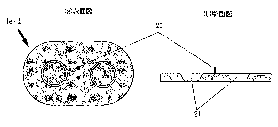
尚、本実験では、包装材料としてアルミ複合包材(岡田紙業製)、乾燥剤として1.0g(OZO化学製)を使用した。その結果を図20に示した。
【0092】
図20に示す結果より、水を含有している電極部を乾燥状態で保持されている薬物部と同一包装した場合、薬物の経時安定性に悪影響を与えることが確認された。また、電極部と薬物部の同一包装形態に、乾燥剤を使用した場合、薬物安定性は多少向上したが、4例中1例に6ヶ月放置後に電極部の水分の枯渇が発見された。一方、実施例1では、非常に優れた薬物安定性を示した。
【0093】
以上より、電極部と薬物部の一体型の装置では、薬物長期安定性を保証することは、現実的に難しいと判断できる。更に、電極部と薬物部の分離型の装置の場合、乾燥剤の使用も可能であるため、薬物長期安定性は更に向上する。
【0094】
また、本発明のイオントフォレーシス装置は、上記に示した技術構成を有していることから、電流発信部、薬物部、電極部の3部を作動前には、分離した状態で保存できるため、水分に対する安定性に問題がある薬剤(生理活性ペプチド類等)を薬物部に含有させる場合、薬物溶解部を内設する電極部からの水揮散による薬物の経時的分解を懸念する必要は無い。
【0095】
また、電極部からの水揮散の完全防止を目的とした包装を必要としなくなるため、経済的にも改善される。更に、薬物部と電極部が一体であった場合には、薬物溶解部への影響を考慮して使用できなかった乾燥剤等の薬物部の安定性改善剤の使用が可能となるため、薬物の長期安定性が一段と向上する。
【0096】
また本発明では、分離保存されている電流発信部、薬物部、電極部の3部を作動時に導電性スナップコネクターまたは組み立て用補助台により、電極部と薬物部との間に位置ずれが無いように接触させ、更に前記の薬物部のライナーを装置外部に剥離的に引く抜くことにより、薬物部の薬物保持体と電極部の薬物溶解部とが自動的に接合し薬物が活性化されるように構成される。このため、適用時の組み立て操作が容易かつ正確となり、人為的誤差を極力排除でき、薬物の再溶解に必要な水分を精度良く薬物保持体に供給できる。
【0097】
また、導電性スナップコネクターは、電極部と電流発信部の電気的接続手段をも兼ねるため、組み立て後は患者の適用部位に装するだけで治療開始が可能となる。更に、組み立て用補助台を適用時の補助手段として使用すると一段と操作性が向上する。
【0098】
以上のことから、本発明に係るイオントフォレーシス装置によれば、優れた薬理効果を示し、しかも従来の装置では得られない患者へのコンプライアンスの向上が実現される。また、操作面及び機能面に於いても安全性が十分に配慮されているため、高い信頼性を得ることができる。
【0099】
【発明の効果】
本発明によれば、薬物の長期安定性を保証でき、しかも適用時の組み立て操作が容易なイオントフォレーシス装置および組み立て方法を得ることができる。
【図面の簡単な説明】
【図1】本発明に係るイオントフォレーシス装置の使用直前における断面構成を示す図である。
【図2】図2は、薬物部(薬物ユニット)の一実施例を示す図で、(a)は表面図、(b)は内部図、(c)は断面図である。
【図3】電流発信部Iaの構成例を示す図であり、(a)は表面図、(b)は裏面図、(c)は断面図である。
【図4】一体型電極部(電極ユニット)Ib−1の構成例を示す図であり、(a)は表面図、(b)は内部図、(c)は裏面図、(d)は断面図である。
【図5】分離型電極部(電極ユニット)Ib−2の構成例を示す図であり、(a)は表面図、(b)は内部図、(c)は裏面図である。
【図6】導電性スナップコネクターIdの構成例を示す図であり、(a)は表面図、(b)は断面図である。
【図7】組み立て用補助台Ie−1の構成例を示す図であり、(a)は表面図、(b)は断面図である。
【図8】組み立て用補助台Ie−2の構成例を示す図であり、(a)は表面図、(b)は断面図である。
【図9】組み立て用補助台Ie−3の構成例を示す図であり、(a)は表面図、(b)は断面図である。
【図10】組み立て用補助台Ie−4の構成例を示す図であり、(a)は表面図、(b)は断面図である。
【図11】本発明に係る一体型電極部Ib−1を用いたイオントフォレーシス装置の組み立て完了後の形態図であり、(a)は表面図、(b)は裏面図である。
【図12】本発明に係る分離型電極部Ib−2を用いたイオントフォレーシス装置の組み立て完了後の形態図であり、(a)は表面図、(b)は裏面図である。
【図13】電流発信部Iaを接続線30を介して電極部に接続した例であり、(a)は接続コード、(b)は表面図、(c)は裏面図である。
【図14】図14は、一体型電極を用いたイオントフォレーシス装置の組み立て方法の一実施例を示す図であり、(a)は組み立ての工程を、(b)は組み立て用の補助台Ie−4を用いる工程を示す。
【図15】一体型電極を用いたイオントフォレーシス装置の組み立て方法の他の実施例を示す図であり、(a)は組み立ての前半の工程を、(b)は後半の工程をそれぞれ示す。
【図16】図16は、一体型電極を用いたイオントフォレーシス装置の組み立て方法の他の実施例を示す図であり、(a)は組み立ての前半の工程を、(b)は後半の工程をそれぞれ示す。
【図17】分離型電極を用いたイオントフォレーシス装置の組み立て方法の一実施例を示す図であり、(a)は組み立ての前半の工程を、(b)は後半の工程をそれぞれ示す。
【図18】比較例に係るイオントフォレーシス用装置の概略図であり、同図(a)は表面図、(b)は内部及び裏面図、(c)は断面図である。
【図19】実験例1における血清中のサーモンカルシトン濃度の推移を示す図である。
【図20】実験例2における薬物部含有のサーモンカルシトンの残存率の経時変化を示す図である。
【符号の説明】
Ia 電流発信部
Ib−1 一体型電極部
Ib−2 分離型電極部
Ic 薬物部
Id 導電性スナップコネクター
Ie 組み立て用補助台
1 電流調節スイッチ
2 電極端子(電流発信部側)
2’ 電極端子(接続コード側)
3 粘着フィルム
4 バッキング層
5 導電性スナップコネクター用挿入口(電極部)
6 ドナー電極印刷部
7 リファレンス電極印刷部
8 粘着フィルム用ライナー
9 蓋材
10 リファレンス電極側導電層
11 ドナー電極側導電層(通称,薬物溶解部)
12 皮膚側ライナー
13 薬物保持体周辺粘着層
14 薬物保持体
15 導電性スナップコネクター用挿入口(薬物部)
16 ライナー引き抜き用ミシン目
17 電極部側ライナー
18 電極端子固定台
19 電極端子(導電性スナップコネクター側)
20 位置合わせ棒
21 電極部収納用スペース
22 電流発信部固定手段
23 電流発信部収納用スペース
23’ 導電性スナップコネクター収納スペース
24 ライナー折り返し用ミシン目
30 接続線
31 コード接続部(電極部側)
32 コード接続部(電流発信部側)
40 皮膚[0001]
BACKGROUND OF THE INVENTION
The present invention relates to an iontophoresis device suitable for transdermal and transmucosal applications, and more particularly to an in-use active iontophoresis device and an assembly method thereof.
[0002]
[Prior art]
In recent years, various dosage forms have been developed in the field of external preparations, and interest in them has been gradually increasing. The reason for this is that when a drug that is expected to have its pharmacological action locally or systemically is administered from the skin or mucous membrane, the drug can be sustained, and the absorption rate of the drug can be easily adjusted to prevent side effects caused by overdose. Various effects such as the ability to effectively use the drug with little influence of metabolism due to the first-pass effect by the liver as seen in oral administration, and the relatively safe administration of drugs with liver damage, etc. This is because it has the advantage of.
[0003]
However, since normal skin naturally has a protective action against external stimuli, the absorption and permeation of drugs is relatively difficult. Therefore, even if the drug is administered in a dosage form for external use, the amount of the drug necessary for sufficient expression of the drug effect is not easily absorbed. In addition, even in the administration route such as oral, rectal, oral, nasal, sublingual, etc., from the biological membranes other than the skin, depending on the drug, it is difficult to permeate or permeate the relevant biological membrane and has low bioavailability. Many drugs are seen. Therefore, it is highly useful and safe absorption that sufficiently enhances the penetration, permeation and absorption of skin and other biological membranes, shows sufficient pharmacological effects at practical use concentrations, and has low local toxicity and systemic toxicity. A promotion method is desired.
[0004]
Currently, there are chemical promotion methods using absorption promoters and physical promotion methods using iontophoresis and phonophoresis. However, in recent years, iontophoresis has gained some attention. It is expected as an administration method that can solve the above problems.
[0005]
In iontophoresis, a voltage is applied to the skin or mucous membrane, the ionic drug is electrophoresed, and the drug is administered from the skin or mucous membrane. In general, an iontophoresis device includes two electrodes for iontophoresis, an anode and a cathode, which are attached to the skin at a predetermined distance from each other, and the current generated by the current generator is applied to the electrodes. It is configured to be treated by guiding.
[0006]
In addition, this iontophoresis device has a structure in which a drug storage layer and an electrode are combined. In order to maintain the blood concentration of the medicinal component in the body for a certain period of time, in addition to the amount of medicinal component designed in advance, In addition, various additives for maintaining medicinal effects are encapsulated as necessary.
[0007]
This type of iontophoresis device is disclosed in, for example, Japanese Patent Laid-Open Nos. 62-268869, 2-1317979, 3-268769, 3-45271, and 3-504343. No. 3 and Japanese National Publication No. 3-504813.
[0008]
However, these iontophoresis devices are concerned about a decrease in the amount of a set drug due to the degradation of the drug over time when using a drug (such as a bioactive peptide) having a problem in stability in water. The Moreover, drug dilution may occur during storage if the drug is to be administered at a high concentration.
[0009]
In the case of transdermal absorption of peptide drugs by iontophoresis, it is usual to set the drug holding environment to the acidic side or basic side from the isoelectric point of the drug. For this reason, the stability of the additive contained for the purpose of assisting the expression of the pharmacological effect of the physiologically active substance is greatly affected, and the pharmacological effect may be reduced.
[0010]
Furthermore, when physiologically active peptides and the like are stored in a dissolved state, adsorption to the peripheral parts of the members constituting the preparation occurs, and it is very difficult to stably store a predetermined concentration for a long period of time. Is recognized.
[0011]
As another problem, in a device in which a conductive layer containing a drug in a dissolved state exists in direct contact with the electrode immediately after energization, the drug may be electrically decomposed on the electrode surface during energization. It has been reported that there is a concern about the effects on the human body due to the absorption of degraded drugs.
[0012]
[Problems to be solved by the invention]
Many proposals have been made so far to solve such problems. For example, in JP-A-63-102768 and US Pat. No. 5,310,404, a capsule or pouch enclosing water or an electrolyte solution is disposed on the upper part of the electrode structure, and the capsule or pouch is broken during use to form a drug retaining layer. A method of impregnation is disclosed. However, this method is excellent in that the drug can be stored in a stable state (dried), but it takes too much time for the water to uniformly penetrate the entire drug holding layer, and the drug effect is reduced by dilution of the drug. It can happen and is not enough.
[0013]
Japanese Patent No. 2542792 discloses a method in which a drug holding layer and an electrode layer containing an electrolyte are arranged in separate compartments and activated by folding two compartments in a hinge structure when applied. Is disclosed. However, although this method is improved in terms of long-term stability of the drug, there are many factors that lead to human error because there is not enough ingenuity in the activation method at the time of application, and the uniformity of the formulation after activation Is not enough.
[0014]
Japanese Patent Application Laid-Open No. 3-94771 discloses that an ion selective permeable membrane (ion exchange membrane or the like) is installed adjacent to the skin side of the water holding unit, and further a drug is placed on the biological contact surface of the ion selective permeable membrane. Devices have been disclosed that are intended to prevent drug dilution and achieve local high concentration administration of trace amounts of drug by drying and adhering.
[0015]
Further, in JP-A-9-201420, an electrode structure layer, a solution holding layer and a physiologically active substance-containing drug holding layer in a dry state are arranged in this order in a hierarchical structure, and further a solution holding layer, a drug holding layer, An iontophoresis device is disclosed in which a water-impermeable separator layer is disposed between them. This device is configured to automatically join the solution holding layer and the drug holding layer by pulling out the separator layer at the time of activation. This device is very excellent in terms of preventing human error during assembly. However, in this device, since the solution holding layer and the drug holding layer are packaged in the same package, the stability of the drug may be lowered due to leakage of the solution from the solution holding layer, and it is difficult to ensure quality assurance. Moreover, even if it is technically possible to completely prevent the leakage of the solution, it is expected that the manufacturing cost will increase.
[0016]
Thus, the present situation is that an iontophoresis device that can guarantee the long-term stability of a drug, is easy and accurate in assembly, and eliminates human error as much as possible has not yet been obtained.
[0017]
Accordingly, an object of the present invention is to provide an iontophoresis device that can guarantee the long-term stability of a drug and can be easily assembled at the time of application, and an assembly method thereof.
[0018]
[Means for Solving the Problems]
The purpose is to provide an alignment structure for each of the electrode part having the drug dissolving part and the drug part having the drug holding body, and aligning the alignment structure of the drug part with the alignment structure of the electrode part to dissolve the drug holding body. This is achieved by an iontophoresis device configured to be joined to a part. These alignment structures are, for example, openings formed in the electrode part and the drug part, respectively. By aligning both openings of the electrode part and the drug part, both can be aligned accurately and quickly.
[0019]
Further, a similar alignment structure is provided in the current transmission part, and the current transmission part is coupled to the electrode part in accordance with the alignment structure of the electrode part. An electrode terminal can be used for the alignment structure formed in the current transmission part. In this case, an alignment structure may be provided on a terminal connected to the current transmission unit with a connection cord.
[0020]
Further, a connector having a similar alignment structure may be provided, and the alignment structures of the respective parts may be aligned with each other and coupled to the current transmission part and the connector with the electrode part interposed therebetween. By constructing some of the alignment structures with a conductive material, the alignment structures can be used as electrical couplings.
[0021]
The drug part of the iontophoresis device is stored in a separate packaging state from parts such as a current transmission part and an electrode part before use. In use, an arrangement holding means for alignment is used to provide mechanical coupling between the electrode section and the drug section or electrical coupling between the electrode section and the current transmission section. As this arrangement holding means, for example, a current transmission part, an electrode terminal of a conductive snap connector, or an auxiliary table for assembling the apparatus is used. Thus, the device of the present invention is also a device set in which an electrode portion having an alignment structure and a drug portion having a similar alignment structure are separately housed. In addition to this, in this device set, a current transmission part, a connector, or an auxiliary positioning base having the same alignment structure is separately housed from the drug part.
[0022]
The electrode part (electrode unit) used here has a member for holding a conductive layer, a wiring connected to the conductive layer, and an alignment structure formed on at least one of the wiring and the member. This alignment structure is an opening formed in at least one of the wiring and the member. The drug part (drug unit) includes a drug holding body that holds the drug, a peelable cover that protects the drug holding body, and an alignment structure formed on the cover. The alignment structure here is an opening formed at the end of the cover.
[0023]
The iontophoresis device assembling method according to the present invention includes a step of peeling the lid provided on the electrode part, and a structure for aligning both the electrode part and the drug part to match the drug holding body of the drug part. The method includes a step of disposing the drug dissolving portion of the electrode portion, a step of peeling the cover on the drug dissolving portion side of the drug holder, and a step of fixing the drug holder to the electrode portion. In this device, a cover is also arranged on the side of the drug holder opposite to the drug dissolving portion, but when the cover is provided with an opening, the assembly can be completed without peeling the cover. Moreover, when the opening is not provided in the cover on the opposite side, the assembly is finished through a step of peeling at least a part of the cover. That is, the entire cover on the opposite side may be peeled off, or for example, the alignment structure portion of the cover may not be peeled off, but the remaining portion may be peeled off.
[0024]
The alignment of the electrode part and the drug part can be performed using an alignment structure installed on the auxiliary base, the current transmission part or the connector. In this case, for example, the alignment structure of the electrode part and the drug part can be used as an opening, and the alignment structure of the auxiliary table can be used as an alignment bar that can be inserted into the opening. Moreover, those electrode terminals can be used as an alignment structure of the current transmission part and the connector.
[0025]
By doing so, it is possible to obtain an iontophoresis device and an assembling method thereof that can guarantee long-term stability of the drug, are easy and accurate in assembling operation, and eliminate human error as much as possible.
[0026]
DETAILED DESCRIPTION OF THE INVENTION
FIG. 1 is a diagram showing a cross-sectional configuration immediately before use in an iontophoresis device according to the present invention. The components in the figure are illustrated apart from each other for easy understanding of the stacking relationship, but in reality, the layers are in close contact.
[0027]
In the figure, a donor
[0028]
In the iontophoresis device configured as described above, the
[0029]
[Action]
Here, the
[0030]
【Example】
Next, a configuration example of each part of such an iontophoresis device will be described in detail.
[0031]
2A and 2B are diagrams showing an embodiment of a drug part (or drug unit), where FIG. 2A is a surface view, FIG. 2B is an internal view, and FIG. 2C is a cross-sectional view. The drug unit Ic of this embodiment is formed by holding the
[0032]
Next, materials of each part of the drug unit will be described. For the drug carrier peripheral
[0033]
The
[0034]
In addition, it is desirable to contain or attach a drug unstable to moisture to the drug holder in a dry state. This is to improve the stability of the drug and prevent leakage and alteration of the drug. In addition, a moisture-stable drug can be held in a drug holding body in a gel form. As the gel-like drug carrier, a water-soluble polymer or a hydrogel thereof is preferably used. In the preparation method of the gel-like drug carrier, a drug solution such as a water-soluble polymer is kneaded with a drug solution. In order to increase conductivity, electrolytes such as sodium chloride, potassium chloride, sodium carbonate, phosphoric acid and sodium citrate, pH buffering agents such as acetic acid, sodium acetate, phosphoric acid, sodium phosphate, citric acid and sodium citrate Can also be added. Furthermore, it is prepared to such an extent that self-holding property can be maintained, and is spread in a sheet form or a film form. Further, when the self-retaining property is weak, a mesh-like support can be put inside the gel. The thickness of the gel layer is preferably from 0.1 to 2 mm, particularly preferably from 0.3 to 0.8 mm. If it is too thin, the gel strength will be weak, and conversely if it is too thick, drug migration will be inhibited and drug absorption will decrease.
[0035]
The
[0036]
As the drug used in the present invention, any drug in any therapeutic field can be used as long as it dissolves and disperses in water. Particularly, the molecular weight is 1 × 10. 2 ~ 1x10 6 These physiologically active substances are widely used. For example, anesthetics, analgesics, anorexic drugs, anthelmintic drugs, antiasthmatic drugs, anticonvulsants, antidiarrheal drugs, antitumor drugs, antiparkinsonian drugs, anti-itching drugs, sympathomimetic drugs, xanthine derivatives, Cardiovascular drugs such as calcium transport blockers, antipyretic drugs, β-blockers, antiarrhythmic drugs, antihypertensive drugs, diuretics, vasodilators including systemic, coronary, peripheral and cerebrovascular, antimigraine drugs, Sickness, antiemetic, central nervous system stimulant, cough and cold medicine, decoestant, diagnostic agent, hormone agent, parasympathomimetic agent, parasympathomimetic agent, psychostimulant, sedative, tranquilizer, Anti-inflammatory drugs, anti-arthritic drugs, antispasmodics, antidepressants, antipsychotics, antipruritic drugs, anxiolytics, anesthetic antagonists, anticancer drugs, hypnotics, immunosuppressants, muscle relaxants, antiviral drugs, antibiotics Substance, anorexia Drugs, antiemetics, anticholinergics, antihistamines, contraceptives, antithrombotic agents, bone resorption inhibitors, but like a bone formation promoter, but is not limited thereto. These may be used alone or in combination as necessary.
[0037]
Examples of individual drugs include steroids such as estradiol, progesterone, norgestrel, levonorgestrel, norethindrone, medroxyprogesterone acetate, testosterone and their esters, derivatives such as nitro compounds such as nitroglycerin and isosorbides nitrate, nicotine, chlorpheniramine Terfenadine, triprolidine, hydrocorzone, oxicam derivatives such as piroxicam, acetic acid or propionic acid derivatives such as indomethacin, flurbiprofen, ferbinac, diclofenac, ketoprofen, mucopolysaccharides such as thiomcase, buprenorphine, fentanyl, naloxone, codeine, lidocaine, Dihydroergotamine, pizotirin, salbutamol, terbutari Prostaglandins such as misoprostol, emprostil, omeprazole, imipramine, benzamides such as metoclopramine, scopolamine, clonidine, dihydropyridines such as nifedipine, verapamil, ephedrine, pindolol, metoprolol, spironolactone, nicardipine hydrochloride, calcitriol, thiazides such as Hydrochlorothiazide, flunarizine, sydnonimines such as molsidomine, sulfated polysaccharides such as heparin fractions and proteins, and peptides such as insulin and its homologues, calcitonin and its homologues such as elcatonin, protamine, glucagon, globulins, angiotensin I, angiotensin II , Angiotensin III, repressin, vasopressin, soma Statins and its homologues, growth hormone and oxytocin, and salts of those compounds and pharmaceutically acceptable may be acid or base as required and the like. Preferred are anesthetics, hormones, proteins, analgesics, other low molecular weight cations, and the like, and more preferred are peptides or polypeptides such as insulin, calcitonin, calcitonin related gene peptides, vasopressin, desmopressin, prothyrin (TRH). ), Adrenocorticotropic hormone (ACTH), luteinizing hormone releasing hormone (LH-RH), growth hormone releasing hormone (GRH), nerve growth factor (NGF) and other releasing factors, angiotensin (angiotensin), parathyroid hormone ( PTH), luteinizing hormone (LH), prolactin, serum sexually stimulating hormone, pituitary hormone (eg, HGH, HMG, HCG), growth hormone, somatostatin, somatomedin, glucagon, oxytocin, gastrin, cetriin Retin, Endorphin, Enkephalin, Endothelin, Cholecystokinin, Neurotensin, Interferon, Interleukin, Transferrin, Erythropoietin, Superoxide desmutase (SOD), Filgrastim (G-CSF), Vasoactive Intestinal Poly Peptide (VIP), muramyl dipeptide, corticotropin, ungastron, atrial natriuretic peptide (h-ANP) and the like can be mentioned, but are not limited thereto. Of these, peptide hormones are particularly preferred. Further, if necessary, an adsorption inhibitor such as benzalkonium chloride, BSA (bovine serum albumin) and monolauric acid can be used.
[0038]
In the present invention, one or a plurality of the above-mentioned drugs or salts thereof can be held on a drug holder. In addition, the amount of drug is determined for each individual drug so that an effective blood concentration set in advance can be obtained for a valid time when it is applied to the patient, and the size and drug release of the iontophoresis device The area of the surface is determined accordingly.
[0039]
3A and 3B are diagrams showing a configuration example of the current transmission unit Ia, where FIG. 3A is a front view, FIG. 3B is a back view, and FIG. 3C is a cross-sectional view. The current transmission part Ia has a current control circuit built in a plastic molded body. A
[0040]
Specifically, the current transmission unit includes a self-oscillation circuit incorporating a small battery, an appropriate high voltage generation circuit connected to the oscillation circuit, and a control circuit for driving and controlling both the circuits. Also, a bolus (BOLUS) button for temporarily increasing the injection rate of the medicine can be installed. This is a useful function when a painkiller is administered and if the patient desires a temporary dose increase in response to significant pain.
[0041]
Further, the control circuit can be switched on / off manually, with a cycle adapted to the circadian rhythm of the living body and the pattern of 24 hour intervals so that an on-demand medication regime can be realized. Configured to be switched off. Further, since the control circuit can incorporate a microprocessor, it is possible to change the level of the current to be applied over time and the waveform of pulses, sine waves, and the like. In addition, the control circuitry can include biosensors and certain feedback systems that monitor biosignals, evaluate treatment methods, and adjust drug dosages accordingly. It is also possible to set one or more programs predetermined by a pharmaceutical manufacturer, doctor or patient.
[0042]
4A and 4B are diagrams showing a configuration example of the integrated electrode portion Ib-1, where FIG. 4A is a front view, FIG. 4B is an internal view, FIG. 4C is a back view, and FIG. The integrated electrode portion Ib-1 has a
[0043]
In this integrated electrode part Ib-1,
[0044]
FIG. 5 is a diagram showing a configuration example of the separation-type electrode portion Ib-2, where (a) is a front view, (b) is an internal view, and (c) is a back view. The separation-type electrode part Ib-2 has a
[0045]
[0046]
In addition, a well-known electrode structure can be used for these electrode parts. For example, platinum black, titanium, carbon, aluminum, iron, lead, carbon conductive rubber, conductive resin, and the like can be used, and platinum electrodes, silver electrodes, silver chloride electrodes, and the like are particularly desirable.
[0047]
The lid member 9 may be any material as long as it is made of a non-permeable material. For example, an aluminum laminated film is used. When high sealing performance by heat sealing is required, a plurality of films or the like used in the above-described liner are laminated or other polymer resins are coated. This facilitates peeling. For example, an easy peel type laminate film can be used. The laminate film preferably has a 180-degree peel strength of 2000 g or less.
[0048]
A pressure sensitive adhesive is used as an adhesive material of the adhesive film 3 (drug holding member peripheral adhesive layer 13). This pressure-sensitive adhesive can hold the iontophoresis device in contact with the surface of the patient's skin or mucous membrane, and is sufficient to perform good bonding between the drug holder and the drug dissolving portion. Any material can be used as long as it has adhesive strength and is physiologically acceptable to the skin. For example, alkyl acrylates having 4 to 18 carbon atoms of alkyl groups such as acrylic acid and methyl acrylate, ethyl acrylate, -2-ethylhexyl acrylate, isooctyl acrylate, decyl acrylate, lauryl acrylate, stearyl acrylate, etc. Acrylic adhesives consisting of homopolymers or copolymers, methyl methacrylate, ethyl methacrylate, butyl methacrylate, 2-ethylhexyl methacrylate, isooctyl methacrylate, decyl methacrylate, lauryl methacrylate, stearyl methacrylate, etc. Methacrylic adhesives comprising homopolymers or copolymers of methacrylic acid alkyl esters having 4 to 18 carbon atoms of the alkyl group, silicone adhesives such as polyorganosiloxane and polydimethylsiloxane, natural rubber, poly Isobutylene, polyvinyl ether, polyurethane, polyisobutylene, polybutadiene, styrene - butadiene copolymer, styrene - isoprene copolymer, styrene - isoprene - rubber adhesives such as styrene block copolymer. Further, if necessary, a tackifier and a softener can be blended.
[0049]
As the material of the
[0050]
In addition, these synthetic resin films, sheets, foams, etc. can be used metal foil such as aluminum foil, tin foil, non-woven fabric, laminate with synthetic paper, aluminum vapor deposition or ceramic coating. . Furthermore, in the case where sealed packaging such as heat sealing is required, heat sealable materials can be laminated and used.
[0051]
As a method of laminating the electrode layer on the backing layer, a method of mixing an electrode material with a printing ink for electric power distribution, etc., coating and drying the material of the backing layer, a method of spreading and fixing the electrode material, Alternatively, a method of evaporating an electrode material, a method of producing an electrode material by photoetching, or the like is used. Moreover, it is also possible to further laminate | stack an insulating layer on an electrode printing layer about the part with the possibility of skin contact of an electrode part.
[0052]
In the conductive layer, only water may be inserted, and at least one selected from an ion-exchangeable polymer and a foaming material, a flexible porous material composed of sponge, etc., a water-absorbing polymer, etc. is included. May be. In order to increase conductivity, electrolytes such as sodium chloride, potassium chloride, sodium carbonate, phosphoric acid and sodium citrate, pH buffering agents such as acetic acid, sodium acetate, phosphoric acid, sodium phosphate, citric acid and sodium citrate Can also be added.
[0053]
Specific examples of the conductive layer are usually non-woven fabric, paper, gauze, absorbent cotton, polyethylene or polypropylene having open cells, polypropylene, vinyl acetate, polyolefin foam, polyamide foam, polyurethane, and other porous films, caraya gum, tragacanth gum, xanthan gum, Natural polysaccharides such as starch, gum arabic, locust bean gum, gellan gum, guar gum, carrageenan, gelatin, pectin, agar, sodium alginate or polyvinyl alcohol and partially saponified products thereof, polyvinyl formal, polyvinyl methyl ether and copolymers thereof, polyvinyl pyrrolidone And its copolymers, sodium carboxymethylcellulose, methylcellulose, hydroxyethylcellulose, hydroxymethylcellulose, hydro Aqueous or water-soluble cellulose derivatives such as cypropylmethylcellulose, hydroxypropylcellulose, cellulose acetate phthalate, carboxyvinyl polymer, polyacrylamide and polyacrylamide derivatives, casein, albumin, chitin, chitosan, polyacrylic acid, sodium polyacrylate, polyhema , Polyhema derivatives, methoxyethylene maleic anhydride copolymer, N-vinylacetamide, copolymers of N-vinylacetamide with acrylic acid and / or acrylate, and their cross-linked products with ethylene glycol as required Water-soluble polymers plasticized with glycerin or the like and hydrogels thereof are preferably used, but the present invention is not limited to this. Further, two or more of the above materials may be used in combination. Further, if necessary, an adsorption inhibitor such as benzalkonium chloride, BSA (bovine serum albumin) and monolauric acid can be used.
[0054]
The conductive layer may be blended with an ion exchange polymer for the purpose of removing ions competing with the drug. The ion exchange polymer is appropriately selected from an anion exchange polymer, a cation exchange polymer, and a both ion exchange polymer according to the drug ionicity. In addition, as for the compounding form, there are a method in which fine powder of ion exchange resin is dispersed in the aforementioned polymer and molded into a gel or a method in which a pre-molded film is used, but the present invention is limited to these. Is not to be done.
[0055]
The capacity of the donor electrode side conductive layer (drug dissolving part) depends on the size of the electrode part and the optimal amount of water required by the drug held in the drug part or the water content of the absorbent member in the drug dissolving part. There is no particular limitation. However, if the amount of water is too large, it will cause leakage of the drug re-dissolution solution, and if it is too small, the drug in the drug part cannot be completely dissolved, resulting in a decrease in medicinal effect. Therefore, the water content is preferably about the maximum water absorption amount of the drug carrier. When hydrogel is used for the drug dissolution part, water separation is 10 mg / cm 2 ~ 100mg / cm 2 Is particularly preferred. Furthermore, the hydrogel must have a gel strength that does not cause breakage during assembly and when worn on the skin. 2 ~ 1500g / cm 2 It is desirable to have a gel strength of
[0056]
The amount of water necessary for drug dissolution of the drug holder is controlled in advance in the drug dissolution part. Thereby, at the time of use, an accurate water amount can be reliably and quickly supplied to the drug holder, so that the therapeutic effect is accurate. In addition, treatment operation and treatment time can be shortened.
[0057]
6A and 6B are diagrams illustrating a configuration example of the conductive snap connector Id, in which FIG. 6A is a front view and FIG. 6B is a cross-sectional view. In this connector Id, two electrode terminals 19 (male or female) are installed on the electrode
[0058]
The connection between the current transmission part Ia and the electrode part Ib is configured such that the electrode part Ib is sandwiched between the electrode terminal on the current transmission part side and the electrode terminal on the conductive snap connector Id side. Since the electrode terminal on the conductive snap connector side comes into contact with the electrode printing part (anode and cathode) of the electrode part by the connection, the current transmission part and the electrode part become conductive, and electrical coupling is realized.
[0059]
In addition, when the drug part is inserted and connected between the current transmission part and the electrode part at the time of assembling the device, the electrode terminal is a mechanical coupling means for the purpose of aligning the electrode part and the drug part. It also has the function. Thus, the current transmission part and the electrode terminal of the conductive snap connector occupy an important position as an assembly means of the apparatus.
[0060]
In addition, as a connection form between the current transmission unit and the electrode unit, there are a case where it is used in a cordless manner or a case where it is used in a remote control operation by a cord. In the former case, when it is desired to treat easily, a small current transmission part is directly connected to the electrode part. On the other hand, in the latter case, a dedicated connection cord is connected between the current transmitter and the electrode when it is desired to treat the current transmitter while operating it. In addition, the connection means for the purpose of the connection of the electric current transmission part side and the electroconductive snap connector side is comprised in the both ends of the connection cord. In this embodiment, electrode terminals (each of an anode and a cathode) are incorporated in a plastic molded body as connection means so that the current transmitting part side and the electrode terminal on the conductive snap connector side can be connected. The connection means is not limited to the electrode terminal, and the shape and connection state of the connection means can be changed at any time. Preferably, the connection means on the conductive snap connector side desirably has a structure in which the drug part and the electrode part can be held firmly without misalignment.
[0061]
FIGS. 7A and 7B are diagrams illustrating a configuration example of the assembly auxiliary stand Ie-1, in which FIG. 7A is a front view and FIG. 7B is a cross-sectional view. The auxiliary base Ie-1 has an electrode
[0062]
This auxiliary assembly base has been devised to facilitate operation when a patient assembles the apparatus. In the present embodiment, the electrode
[0063]
Further, the
[0064]
8A and 8B are diagrams showing a configuration example of the auxiliary assembly base Ie-2, where FIG. 8A is a front view and FIG. 8B is a cross-sectional view. The auxiliary base Ie-2 is configured to have a current transmission
[0065]
FIG. 9 is a diagram illustrating a configuration example of the assembly auxiliary stand Ie-3, where (a) is a front view and (b) is a cross-sectional view. The auxiliary stand Ie-3 has a current transmission
[0066]
FIG. 10 is a diagram illustrating a configuration example of the assembly auxiliary base Ie-4, where (a) is a front view and (b) is a cross-sectional view. The auxiliary base Ie-4 is configured to include a
[0067]
In addition, the structure of the auxiliary stand for assembly can be used in combination with the above structure depending on the form of the apparatus and the assembly procedure, and the shape can be changed. The material of the assembly support base is not particularly limited as long as it can be molded from paper, metal, wood, plastic film (polypropylene, Teflon, vinyl chloride), etc., but it is highly molded with a thickness of 0.5 mm or more. A plastic film having retentivity is preferred.
[0068]
FIGS. 11A and 11B are views after completion of the assembly of the iontophoresis device using the integrated electrode portion Ib-1 according to the present invention, where FIG. 11A is a front view and FIG. 11B is a rear view. As shown in the figure, the current transmission part Ia is arranged on the surface of the electrode part, and the conductive snap connector Id is arranged on the back surface. The electrode is sandwiched and fixed by the current transmission part Ia and the conductive snap connector Id.
[0069]
FIGS. 12A and 12B are views after completion of the assembly of the iontophoresis device using the separation-type electrode portion Ib-2 according to the present invention, where FIG. 12A is a front view and FIG. 12B is a rear view. Similarly, in the case of this example, the current transmission portion Ia is disposed on the surface of the wiring connected to the electrode portion, and the conductive snap connector Id is disposed on the back surface. The wiring is fixed between the current transmission part Ia and the conductive snap connector Id.
[0070]
FIG. 13 is an example in which the current transmission part Ia is connected to the electrode part via the
[0071]
Next, an embodiment of an assembly method for an iontophoresis device using such components will be described.
[0072]
(Example 1)
FIGS. 14A and 14B are diagrams showing an example of an assembly method of an iontophoresis device using an integrated electrode, in which FIG. 14A shows an assembly process, and FIG. 14B shows an auxiliary stand Ie-4 for assembly. The process used is shown.
[0073]
First, as shown in (a) (1) in the figure, the lid member 9 of the integral electrode part is peeled off, and the
[0074]
Further, as shown in FIG. 5B, in this embodiment, the apparatus can be assembled using the assembly auxiliary base Ie-4. According to the iontophoresis device of the present embodiment, the assembly operation at the time of application can be easily and accurately performed as well as the long-term stability improvement of the drug. Thereby, an artificial error can be eliminated as much as possible, and water necessary for re-dissolution of the drug can be supplied to the drug holder with high accuracy. In addition, since the conductive snap connector serves both as an alignment means for the electrode part and the drug part and an electrical connection means for the electrode part and the current transmission part, it can be easily mounted on the application site of the patient after the device is assembled. .
[0075]
(Example 2)
FIGS. 15A and 15B are diagrams showing another embodiment of the method of assembling an iontophoresis device using an integrated electrode, where FIG. 15A shows the first half of the assembly process and FIG. 15B shows the second half of the process. .
[0076]
First, as shown in (a) (1) in the figure, after the electrode part is installed according to the
[0077]
Next, the conductive snap connector Id and the current transmission part Ia are installed in the same form as in Example 1 as shown in FIG. As shown in FIG. 8 (8), the
[0078]
(Example 3)
FIGS. 16A and 16B are diagrams showing another embodiment of the method of assembling an iontophoresis device using an integrated electrode, where FIG. 16A shows the first half of the assembly process and FIG. 16B shows the second half of the process. .
[0079]
First, as shown in (a) (1) in the figure, the current transmission part Ia is incorporated in the current transmission
[0080]
Then, after the
[0081]
Example 4
FIGS. 17A and 17B are diagrams showing an embodiment of an assembly method of an iontophoresis device using a separation-type electrode, where FIG. 17A shows the first half of the assembly process and FIG. 17B shows the second half of the process.
[0082]
First, as shown in FIG. 2A, the two electrode terminals (male) of the current transmission part Ia are directed upward in the current transmission
[0083]
Then, after pulling out the
[0084]
The operation procedure of the assembling method is not limited to this, and can be changed flexibly according to the usage pattern of the patient. For example, a structure in which the lid member 9 of the electrode part has a function as a coupling means and the lid member is pulled out in a peelable manner is also possible. Further, the auxiliary base can be used as an auxiliary means for mounting the application site without being removed from the auxiliary base after the assembly is completed, and the auxiliary base can be removed after the mounting is completed. As described above, the iontophoresis device according to the present embodiment uses the conductive snap connector and the current transmission unit to integrate and activate the electrode unit (anode unit and cathode unit) (position alignment). ) And operability (easiness of handling) after activation can be carried out at a time, so that a desired function can be sufficiently provided. Further, since the electrode parts (anode part and cathode part) can be produced separately and independently, there is an advantage in terms of production equipment and quality assurance as compared with the integrated electrode part.
[0085]
(Comparative Example 1)
18A and 18B are schematic views of an iontophoresis device according to a comparative example, in which FIG. 18A is a front view, FIG. 18B is an internal and rear view, and FIG. 18C is a cross-sectional view. This comparative example is an apparatus in which the electrode part and the drug part are integrally installed via a backing, and the
[0086]
(Experimental example 1)
Measurement of blood salmon calcitonin concentration
In this experimental example, the following contents of Example 1 and Comparative Example 1 were newly produced and used. In Example 1 and Comparative Example 1, the silver printing part (anode) is 2.5 cm. 2 1.0 g of 1.5% agar gel containing a citrate buffer (33 mM, pH 5) was filled in the conductive layer adjacent to the silver chloride printed part (cathode) and sodium chloride-containing polyvinyl alcohol (UF- 250 g (manufactured by Unitika) was filled to prepare an electrode part. The drug part is a drug holding film (Biodyne +, manufactured by Ball Co.) 3.46 cm. 2 Salmon calcitonin 20IU was added dropwise to the sample and dried.
[0087]
After the iontophoresis devices in Example 1 and Comparative Example 1 manufactured as described above were assembled according to the example, they were mounted on the abdomen of an SD rat (body weight 250 g), using the donor electrode as the anode and the reference electrode as the cathode. 12V pulse depolarization energization was performed from the current transmitter. In addition, the assembly of the iontophoresis device was carried out by four males in each of the examples and comparative examples. Blood was collected from the rat jugular vein over time to obtain serum. Serum calcitonin concentration in serum was measured using a radioimmunoace kit (Peninsula salmon calcitonin quantification kit). The results are shown in FIG.
[0088]
In the results shown in FIG. 19, the salmon calcitonin blood concentration after about 5 minutes is 2056 ± 136 pg / ml (mean value ± standard error) in the case of Example 1, and 1867 ± 548 pg / ml in the case of Comparative Example 1. In addition, the trend of blood concentration was almost the same, and no significant difference was observed between them. However, it was found that Comparative Example 1 had more variations than Example 1, and that an artificial error during assembly greatly affected the blood concentration. As a result, the apparatus and the assembly method of Example 1 are easy and accurate for the assembly operation at the time of use, can eliminate the human error as much as possible, and accurately provide the drug holder with water necessary for re-dissolution of the drug. It turns out that it can supply.
[0089]
(Experimental example 2)
Evaluation of stability over time of salmon calcitonin containing drug part
About Example 1 and Comparative Example 1 used in Experimental Example 1, packaging was carried out with the contents of Table 1 below, and 25 ° C., 65% R.D. H. The temporal stability of salmon calcitonin under standing conditions was evaluated.
[0090]
[Table 1]
In this experiment, an aluminum composite packaging material (Okada Paper Industry) was used as the packaging material, and 1.0 g (OZO Chemical) was used as the desiccant. The results are shown in FIG.
[0092]
From the results shown in FIG. 20, it was confirmed that when the electrode part containing water was packed in the same way as the drug part held in a dry state, the stability over time of the drug was adversely affected. In addition, when a desiccant was used in the same packaging form of the electrode part and the drug part, the drug stability was somewhat improved, but in one of the four cases, dehydration of the electrode part was found after being left for 6 months. On the other hand, Example 1 showed very good drug stability.
[0093]
From the above, it can be judged that it is practically difficult to ensure long-term drug stability in an integrated device of an electrode part and a drug part. Furthermore, in the case of a separate type device having an electrode part and a drug part, it is possible to use a desiccant, so that the long-term stability of the drug is further improved.
[0094]
In addition, since the iontophoresis device of the present invention has the above-described technical configuration, it is possible to store the three parts of the current transmission unit, the drug unit, and the electrode unit in a separated state before operation. Therefore, when drugs that have problems with moisture stability (such as bioactive peptides) are included in the drug part, there is a need to be concerned about the degradation of the drug over time due to water volatilization from the electrode part in which the drug dissolution part is installed. No.
[0095]
Moreover, since the packaging for the purpose of completely preventing the volatilization of water from the electrode portion is not required, it is economically improved. Furthermore, when the drug part and the electrode part are integrated, it becomes possible to use a drug part stability improving agent such as a desiccant that could not be used in consideration of the influence on the drug dissolving part. The long-term stability is further improved.
[0096]
Further, in the present invention, the three parts of the current transmitting part, the drug part, and the electrode part that are separated and stored are not misaligned between the electrode part and the drug part by the conductive snap connector or the auxiliary assembly base during operation. And the drug part liner is pulled out of the apparatus in a peeled manner so that the drug holding body in the drug part and the drug dissolving part in the electrode part are automatically joined to activate the drug. Configured. For this reason, the assembly operation at the time of application becomes easy and accurate, human error can be eliminated as much as possible, and moisture necessary for re-dissolution of the drug can be supplied to the drug holder with high accuracy.
[0097]
In addition, since the conductive snap connector also serves as an electrical connection means for the electrode part and the current transmission part, treatment can be started by simply mounting it on the application site of the patient after assembly. Furthermore, when the assembly auxiliary stand is used as an auxiliary means at the time of application, the operability is further improved.
[0098]
From the above, according to the iontophoresis device according to the present invention, an excellent pharmacological effect is shown, and an improvement in compliance with a patient that cannot be obtained by a conventional device is realized. In addition, since safety is sufficiently taken into consideration in terms of operation and functions, high reliability can be obtained.
[0099]
【The invention's effect】
According to the present invention, it is possible to obtain an iontophoresis device and an assembling method that can guarantee the long-term stability of a drug and can be easily assembled at the time of application.
[Brief description of the drawings]
FIG. 1 is a diagram showing a cross-sectional configuration immediately before use of an iontophoresis device according to the present invention.
FIG. 2 is a view showing one embodiment of a drug portion (drug unit), where (a) is a surface view, (b) is an internal view, and (c) is a cross-sectional view.
3A and 3B are diagrams illustrating a configuration example of a current transmission unit Ia, in which FIG. 3A is a front view, FIG. 3B is a back view, and FIG. 3C is a cross-sectional view.
FIGS. 4A and 4B are diagrams showing a configuration example of an integrated electrode unit (electrode unit) Ib-1, where FIG. 4A is a front view, FIG. 4B is an internal view, FIG. 4C is a back view, and FIG. FIG.
5A and 5B are diagrams illustrating a configuration example of a separation-type electrode unit (electrode unit) Ib-2, where FIG. 5A is a front view, FIG. 5B is an internal view, and FIG. 5C is a back view.
6A and 6B are diagrams showing a configuration example of a conductive snap connector Id, in which FIG. 6A is a front view and FIG. 6B is a cross-sectional view.
FIGS. 7A and 7B are diagrams illustrating a configuration example of the assembly auxiliary stand Ie-1, in which FIG. 7A is a front view and FIG. 7B is a cross-sectional view.
FIGS. 8A and 8B are diagrams showing a configuration example of the assembly auxiliary stand Ie-2, where FIG. 8A is a front view and FIG. 8B is a cross-sectional view.
FIGS. 9A and 9B are diagrams showing a configuration example of the assembly auxiliary stand Ie-3, where FIG. 9A is a front view and FIG. 9B is a cross-sectional view.
FIGS. 10A and 10B are diagrams showing a configuration example of the auxiliary assembly base Ie-4, where FIG. 10A is a front view and FIG. 10B is a cross-sectional view.
FIGS. 11A and 11B are configuration diagrams after the assembly of the iontophoresis device using the integrated electrode portion Ib-1 according to the present invention is completed, in which FIG. 11A is a front view and FIG. 11B is a rear view.
FIGS. 12A and 12B are views after completion of the assembly of the iontophoresis device using the separation-type electrode portion Ib-2 according to the present invention, wherein FIG. 12A is a front view and FIG.
13 is an example in which the current transmission part Ia is connected to the electrode part via the
FIGS. 14A and 14B are diagrams showing an example of an assembly method of an iontophoresis device using an integrated electrode, where FIG. 14A shows an assembly process and FIG. 14B shows an auxiliary table for assembly. The process using Ie-4 is shown.
FIGS. 15A and 15B are diagrams showing another embodiment of a method for assembling an iontophoresis device using an integrated electrode, where FIG. 15A shows the first half of the assembly process, and FIG. 15B shows the second half of the process. .
FIG. 16 is a diagram showing another embodiment of the method of assembling an iontophoresis device using an integrated electrode, where (a) shows the first half of the assembly process, and (b) shows the second half of the process. Each process is shown.
FIGS. 17A and 17B are diagrams showing an example of an assembly method of an iontophoresis device using a separation-type electrode, where FIG. 17A shows the first half of the assembly process, and FIG. 17B shows the second half of the process.
18A and 18B are schematic views of an iontophoresis device according to a comparative example, in which FIG. 18A is a front view, FIG. 18B is an inner and rear view, and FIG. 18C is a cross-sectional view.
FIG. 19 is a graph showing changes in serum salmon calcitones concentration in Experimental Example 1.
20 is a graph showing the change over time in the residual rate of salmon calcitotone containing a drug moiety in Experimental Example 2. FIG.
[Explanation of symbols]
Ia Current transmitter
Ib-1 Integrated electrode section
Ib-2 Separate type electrode section
Ic Drug Department
Id conductive snap connector
Ie Auxiliary stand for assembly
1 Current control switch
2 Electrode terminal (current transmitter side)
2 'Electrode terminal (connection cord side)
3 Adhesive film
4 Backing layer
5 Conductive snap connector insertion slot (electrode part)
6 Donor electrode printing department
7 Reference electrode printing section
8 Liner for adhesive film
9 Lid
10 Reference electrode side conductive layer
11 Donor electrode side conductive layer (commonly known as drug dissolving part)
12 Skin side liner
13 Adhesive layer around drug carrier
14 Drug carrier
15 Conductive snap connector insertion slot (drug part)
16 Perforation for liner removal
17 Electrode side liner
18 Electrode terminal fixing base
19 Electrode terminal (conductive snap connector side)
20 Alignment stick
21 Electrode storage space
22 Current transmitter fixing means
23 Space for storing current transmitter
23 'conductive snap connector storage space
24 Liner perforation
30 connecting lines
31 Cord connection (electrode side)
32 Cord connection (current transmission side)
40 skin
Claims (14)
Priority Applications (8)
| Application Number | Priority Date | Filing Date | Title |
|---|---|---|---|
| JP36864897A JP4154016B2 (en) | 1997-12-30 | 1997-12-30 | Iontophoresis device and assembly method thereof |
| CA002316777A CA2316777A1 (en) | 1997-12-30 | 1998-12-21 | Iontophoresis device and method of assembling the same |
| AU16844/99A AU754571B2 (en) | 1997-12-30 | 1998-12-21 | Iontophoresis device and method of assembling the same |
| PCT/JP1998/005775 WO1999033517A1 (en) | 1997-12-30 | 1998-12-21 | Iontophoresis device and method of assembling the same |
| CN98813437A CN1284005A (en) | 1997-12-30 | 1998-12-21 | Iontophoresis device and method of assembling same |
| EP98961446A EP1050319A4 (en) | 1997-12-30 | 1998-12-21 | Iontophoresis device and method of assembling the same |
| KR1020007007320A KR20010033786A (en) | 1997-12-30 | 1998-12-21 | Iontophoresis device and method of assembling the same |
| US09/581,261 US6587717B1 (en) | 1997-12-30 | 1998-12-21 | Iontophoresis device and method of assembling the same |
Applications Claiming Priority (1)
| Application Number | Priority Date | Filing Date | Title |
|---|---|---|---|
| JP36864897A JP4154016B2 (en) | 1997-12-30 | 1997-12-30 | Iontophoresis device and assembly method thereof |
Publications (2)
| Publication Number | Publication Date |
|---|---|
| JPH11192313A JPH11192313A (en) | 1999-07-21 |
| JP4154016B2 true JP4154016B2 (en) | 2008-09-24 |
Family
ID=18492375
Family Applications (1)
| Application Number | Title | Priority Date | Filing Date |
|---|---|---|---|
| JP36864897A Expired - Fee Related JP4154016B2 (en) | 1997-12-30 | 1997-12-30 | Iontophoresis device and assembly method thereof |
Country Status (8)
| Country | Link |
|---|---|
| US (1) | US6587717B1 (en) |
| EP (1) | EP1050319A4 (en) |
| JP (1) | JP4154016B2 (en) |
| KR (1) | KR20010033786A (en) |
| CN (1) | CN1284005A (en) |
| AU (1) | AU754571B2 (en) |
| CA (1) | CA2316777A1 (en) |
| WO (1) | WO1999033517A1 (en) |
Cited By (1)
| Publication number | Priority date | Publication date | Assignee | Title |
|---|---|---|---|---|
| WO2011099512A1 (en) * | 2010-02-12 | 2011-08-18 | テルモ株式会社 | Iontophoresis patch |
Families Citing this family (12)
| Publication number | Priority date | Publication date | Assignee | Title |
|---|---|---|---|---|
| US6745071B1 (en) * | 2003-02-21 | 2004-06-01 | Birch Point Medical, Inc. | Iontophoretic drug delivery system |
| KR100610252B1 (en) * | 2004-07-01 | 2006-08-10 | 주식회사 엘지생활건강 | Iontophoresis device |
| CA2589532A1 (en) * | 2004-12-09 | 2006-06-15 | Transcutaneous Technologies Inc. | Iontophoresis device |
| CN101091816B (en) * | 2006-06-19 | 2010-06-16 | 刘珮珮 | Device and method for improving permeability of preparation to living body skin |
| US8197844B2 (en) | 2007-06-08 | 2012-06-12 | Activatek, Inc. | Active electrode for transdermal medicament administration |
| US8862223B2 (en) | 2008-01-18 | 2014-10-14 | Activatek, Inc. | Active transdermal medicament patch and circuit board for same |
| US20090299267A1 (en) * | 2008-05-28 | 2009-12-03 | Isis Biopolymer Llc | Iontophoretic drug delivery system with procedure window |
| JP5514823B2 (en) * | 2008-09-05 | 2014-06-04 | テイコク ファーマ ユーエスエイ、インコーポレーテッド | Iontophoresis drug delivery packaging |
| EP2427245A1 (en) * | 2009-05-08 | 2012-03-14 | Isis Biopolymer, Inc. | Iontophoretic device with improved counterelectrode |
| US20110092881A1 (en) * | 2009-05-08 | 2011-04-21 | Isis Biopolymer Inc. | Iontophoretic device with contact sensor |
| USD678534S1 (en) | 2010-07-20 | 2013-03-19 | Iontera, Inc. | Iontophoretic device for application to the brow/forehead of a person |
| EP2886153A1 (en) | 2013-12-20 | 2015-06-24 | LTS LOHMANN Therapie-Systeme AG | System for the transdermal delivery of an active substance |
Family Cites Families (16)
| Publication number | Priority date | Publication date | Assignee | Title |
|---|---|---|---|---|
| US4666441A (en) * | 1985-12-17 | 1987-05-19 | Ciba-Geigy Corporation | Multicompartmentalized transdermal patches |
| JPS62268569A (en) | 1986-05-19 | 1987-11-21 | 株式会社アドバンス | Reservoir electrode for iontophoresis |
| JPS63102768A (en) | 1986-10-20 | 1988-05-07 | 山之内製薬株式会社 | Novel plaster structure for iontophoresis |
| CA2001446C (en) | 1988-10-28 | 2000-08-01 | Joseph Bradley Phipps | Iontophoresis electrode |
| CA2001444C (en) | 1988-10-28 | 2000-07-25 | Darrel F. Untereker | Iontophoresis electrode |
| JPH02131779A (en) | 1988-11-11 | 1990-05-21 | Takara Kogyo Kk | Ion lead-in device |
| JPH0345271A (en) | 1989-07-12 | 1991-02-26 | Teijin Ltd | Ion phoresis device |
| JP3267291B2 (en) | 1990-03-20 | 2002-03-18 | 株式会社きもと | Iontophoresis film |
| US5310404A (en) * | 1992-06-01 | 1994-05-10 | Alza Corporation | Iontophoretic delivery device and method of hydrating same |
| JP2542792B2 (en) * | 1992-11-05 | 1996-10-09 | ベクトン・ディッキンソン・アンド・カンパニー | User-operated iontophoretic device |
| FR2709670B1 (en) * | 1993-09-10 | 1995-10-20 | Asulab Sa | Device in three modules for transdermal administration of drugs by electrophoresis or iontophoresis. |
| EP0739644A4 (en) * | 1994-09-30 | 1998-12-09 | Advance Kk | Interface for iontophoretic percutaneous administration, and agent and method for treating the skin for that purpose |
| US5837281A (en) * | 1995-03-17 | 1998-11-17 | Takeda Chemical Industries, Ltd. | Stabilized interface for iontophoresis |
| EP0747092B1 (en) * | 1995-06-09 | 2003-12-03 | Hisamitsu Pharmaceutical Co., Inc. | Matrix for iontophoresis |
| US5797867A (en) * | 1996-09-27 | 1998-08-25 | Becton Dickinson And Company | Iontophoretic drug delivery system, including method for activating same for attachment to patient |
| JPH11239621A (en) * | 1998-02-25 | 1999-09-07 | Hisamitsu Pharmaceut Co Inc | Iontophoresis device |
-
1997
- 1997-12-30 JP JP36864897A patent/JP4154016B2/en not_active Expired - Fee Related
-
1998
- 1998-12-21 US US09/581,261 patent/US6587717B1/en not_active Expired - Fee Related
- 1998-12-21 CN CN98813437A patent/CN1284005A/en active Pending
- 1998-12-21 WO PCT/JP1998/005775 patent/WO1999033517A1/en not_active Ceased
- 1998-12-21 KR KR1020007007320A patent/KR20010033786A/en not_active Withdrawn
- 1998-12-21 EP EP98961446A patent/EP1050319A4/en not_active Withdrawn
- 1998-12-21 CA CA002316777A patent/CA2316777A1/en not_active Abandoned
- 1998-12-21 AU AU16844/99A patent/AU754571B2/en not_active Ceased
Cited By (2)
| Publication number | Priority date | Publication date | Assignee | Title |
|---|---|---|---|---|
| WO2011099512A1 (en) * | 2010-02-12 | 2011-08-18 | テルモ株式会社 | Iontophoresis patch |
| US9517331B2 (en) | 2010-02-12 | 2016-12-13 | Terumo Kabushiki Kaisha | Iontophoresis patch |
Also Published As
| Publication number | Publication date |
|---|---|
| US6587717B1 (en) | 2003-07-01 |
| KR20010033786A (en) | 2001-04-25 |
| WO1999033517A1 (en) | 1999-07-08 |
| AU754571B2 (en) | 2002-11-21 |
| EP1050319A1 (en) | 2000-11-08 |
| EP1050319A4 (en) | 2004-12-15 |
| CN1284005A (en) | 2001-02-14 |
| CA2316777A1 (en) | 1999-07-08 |
| AU1684499A (en) | 1999-07-19 |
| JPH11192313A (en) | 1999-07-21 |
Similar Documents
| Publication | Publication Date | Title |
|---|---|---|
| JP4154017B2 (en) | Iontophoresis device and drug unit | |
| US6654635B1 (en) | Iontophoresis device | |
| JP3119486B2 (en) | Electrode for iontophoresis and device using the same | |
| AU699984B2 (en) | Plaster structure for iontophoresis | |
| JPWO1995035132A1 (en) | IONTOPHORPHY ELECTRODE AND DEVICE USING THE SAME | |
| JP2000316991A (en) | Electrode structural body for iontophoresis device and its manufacture | |
| JP4154016B2 (en) | Iontophoresis device and assembly method thereof | |
| JPH03151982A (en) | Method and device for percutaneous administration of protain and peptide drug | |
| JPH09201420A (en) | Device for iontophoresis being active on use | |
| JP2009509682A (en) | Pulsed delivery of gonadotropin-releasing hormone from pre-filled combined electrical delivery patches | |
| JPH0852224A (en) | Device for iontophoresis | |
| JPH08229140A (en) | Device for iontophoresis | |
| JP2845501B2 (en) | Interface for iontophoresis | |
| AU2003200165B2 (en) | Iontophoresis device and drug unit | |
| JP3119488B2 (en) | Iontophoresis device for water-soluble steroids | |
| JPWO1996011034A1 (en) | Method for administering water-soluble steroids by iontophoresis |
Legal Events
| Date | Code | Title | Description |
|---|---|---|---|
| A621 | Written request for application examination |
Free format text: JAPANESE INTERMEDIATE CODE: A621 Effective date: 20040922 |
|
| A131 | Notification of reasons for refusal |
Free format text: JAPANESE INTERMEDIATE CODE: A131 Effective date: 20070626 |
|
| A521 | Request for written amendment filed |
Free format text: JAPANESE INTERMEDIATE CODE: A523 Effective date: 20070827 |
|
| A131 | Notification of reasons for refusal |
Free format text: JAPANESE INTERMEDIATE CODE: A131 Effective date: 20080226 |
|
| A521 | Request for written amendment filed |
Free format text: JAPANESE INTERMEDIATE CODE: A523 Effective date: 20080424 |
|
| TRDD | Decision of grant or rejection written | ||
| A01 | Written decision to grant a patent or to grant a registration (utility model) |
Free format text: JAPANESE INTERMEDIATE CODE: A01 Effective date: 20080701 |
|
| A01 | Written decision to grant a patent or to grant a registration (utility model) |
Free format text: JAPANESE INTERMEDIATE CODE: A01 |
|
| A61 | First payment of annual fees (during grant procedure) |
Free format text: JAPANESE INTERMEDIATE CODE: A61 Effective date: 20080707 |
|
| R150 | Certificate of patent or registration of utility model |
Free format text: JAPANESE INTERMEDIATE CODE: R150 |
|
| FPAY | Renewal fee payment (event date is renewal date of database) |
Free format text: PAYMENT UNTIL: 20110711 Year of fee payment: 3 |
|
| FPAY | Renewal fee payment (event date is renewal date of database) |
Free format text: PAYMENT UNTIL: 20120711 Year of fee payment: 4 |
|
| FPAY | Renewal fee payment (event date is renewal date of database) |
Free format text: PAYMENT UNTIL: 20130711 Year of fee payment: 5 |
|
| R250 | Receipt of annual fees |
Free format text: JAPANESE INTERMEDIATE CODE: R250 |
|
| LAPS | Cancellation because of no payment of annual fees |