JP4153185B2 - Polymer resin film and gas barrier film using the same - Google Patents
Polymer resin film and gas barrier film using the same Download PDFInfo
- Publication number
- JP4153185B2 JP4153185B2 JP2001286753A JP2001286753A JP4153185B2 JP 4153185 B2 JP4153185 B2 JP 4153185B2 JP 2001286753 A JP2001286753 A JP 2001286753A JP 2001286753 A JP2001286753 A JP 2001286753A JP 4153185 B2 JP4153185 B2 JP 4153185B2
- Authority
- JP
- Japan
- Prior art keywords
- oxide
- gas barrier
- layer
- film
- polymer resin
- Prior art date
- Legal status (The legal status is an assumption and is not a legal conclusion. Google has not performed a legal analysis and makes no representation as to the accuracy of the status listed.)
- Expired - Fee Related
Links
Images


Landscapes
- Laminated Bodies (AREA)
Description
【0001】
【発明の属する技術分野】
本発明は、食品や医薬品等の包装材料や電子デバイス等のパッケージ材料として主に用いられるガスバリアフィルムの基材として用いられる高分子樹脂フィルム、及びこれを用いたガスバリアフィルムに関する。
【0002】
【従来の技術】
ガスバリアフィルムは、主に、(イ)内容物の品質を変化させる原因となる酸素や水蒸気等の影響を防ぐために、食品や医薬品等の包装材料として用いられたり、(ロ)液晶表示パネルやEL表示パネル等に形成されている素子が、水蒸気に触れて性能劣化するの避けるために、電子デバイス等のパッケージ材料として用いられている。ガスバリアフィルムは、その基材として高分子樹脂フィルムを用い、この高分子樹脂の片面又は両面にガスバリア性を有するフィルムを貼り合わせるものや、ガスバリア性を有するガスバリア層を湿式成層または乾式成層するものが従来より知られている。
【0003】
【発明が解決しようとする課題】
しかしながら、従来のガスバリアフィルムは、2cc/m2/day程度の酸素透過率(OTR)や、2g/m2/day程度の水蒸気透過率(WVTR)を有するにすぎず、より高いガスバリア性を有する用途、例えば有機ELの封止用に使用される場合には、未だ不十分なものであった。
【0004】
本発明は、上記問題に鑑みなされたものであり、従来のガスバリアフィルムと比べて、極めて優れたガスバリア性を有するガスバリアフィルムを提供することを課題とする。
【0005】
【課題を解決するための手段】
本発明は、上記課題を解決するために、請求項1に記載するように、ガスバリア性を有するガスバリア層が蒸着法により形成されるガスバリアフィルムの基材として用いられる高分子樹脂フィルムであり、当該高分子樹脂フィルムは、フィルム本体部分と、その表面に含有せしめられた鉱物と、から構成されていることを特徴とする高分子樹脂フィルムを提供する。
【0006】
本発明によれば、本発明の高分子樹脂フィルムを基材として用い、その片面又は両面に蒸着法によりガスバリア層を形成することによってガスバリアフィルムを製造した場合、ガスバリア層の酸素透過率、及び水蒸気透過率を従来のそれよりも小さくすること、つまり、ガスバリアフィルムのガスバリア性を向上することができる。
【0007】
本発明の高分子樹脂フィルムを基材として用いることでガスバリアフィルムの性能が向上する理由については、学術的又は理論的に説明することは困難である。しかしながら、本発明の高分子樹脂フィルムの片面又は両面に蒸着法によって形成されるガスバリア層が従来のガスバリア層に比べ緻密な層として形成されていることがその理由であると考えることができる。つまり、本発明の高分子樹脂フィルムは、そのの表面に鉱物が含有されていることに特徴を有するものであるが、この鉱物中には金属が存在しており、そのため蒸着法によってガスバリア層を形成しようとした場合には、高分子樹脂フィルムの表面にある鉱物(その中でも特に金属)が、ガスバリア層が高分子樹脂フィルム表面に蒸着して層に成長するための「核」として作用していると考えることができる。また、蒸着法によりガスバリア層を形成する場合には、ガスバリア層の原料を蒸発せしめるために高電圧雰囲気とするが、本発明の高分子樹脂の表面に存在する鉱物は、絶縁性を有しているためこれにより放電電圧が上昇し、そうすると、蒸発したガスバリア層の原料が、基材としての高分子樹脂フィルムの表面に強くたたきつけられることとなり、結果として緻密な層が形成されていると考えることもできる。
【0008】
また、本発明は、上記課題を解決するために、請求項2に記載するように、請求項1に記載の高分子樹脂フィルムにおいて、前記鉱物が粒子状であり、その粒径が、0.5〜2μmであって、隣り合う鉱物同士の間隔が、20〜100μmであることを特徴とする高分子樹脂フィルムを提供する。
【0009】
本発明によれば、請求項1に記載の高分子樹脂フィルムにおいて、前記鉱物が粒子状であり、その粒径が、0.5〜2μmであって、隣り合う鉱物同士の間隔が、20〜100μmであるので、ガスバリア層形成の「核」となる鉱物が適当な大きさで、ほぼ均一に基材表面に分散されている状態と考えることができ、形成されるガスバリア層を緻密な層とすることができる。
【0010】
さらに、本発明は、上記目的を解決するために、請求項3に記載するように、請求項1または請求項2に記載の高分子樹脂フィルムにおいて、前記鉱物が、カオリナイト、アルナイト、セリサイト、モンモリロナイトのいずれかであることを特徴とする高分子樹脂フィルムを提供する。
【0011】
本発明によれば、前記鉱物が、カオリナイト、アルナイト、セリサイト、モンモリロナイトのいずれかであるので、請求項1または請求項2と同様の作用効果を奏することができるとともに、カオリナイト等の鉱物は、比較的入手が容易であるとともに、その取り扱いも容易だからである。
【0012】
さらに、本発明は、請求項4に記載するように、前記請求項1乃至請求項3のいずれかの請求項に記載の高分子樹脂フィルムが基材として用いられており、この基材の片面又は両面にはガスバリア性を有するガスバリア層が設けられていることを特徴とするガスバリアフィルムを提供する。
【0013】
この発明によれば、実際に本発明の高分子樹脂フィルムをガスバリアフィルムの基材として用いることができ、これにより前述した理由によりガスバリア性に優れたガスバリアフィルムとすることができる。
【0014】
【発明の実施の形態】
図1は、本発明の高分子樹脂フィルムの一例を示す断面構成図である。
【0015】
図1に示すように、本発明の高分子樹脂フィルム1は、フィルム本体部分2とその表面に含有せしめられた粒径状の鉱物3とから構成されていることに特徴を有しており、ガスバリアフィルムの基材として用いられるものである。本発明の高分子樹脂フィルム1をガスバリアフィルムの基材として用いることにより、ガスバリアフィルムの性能を従来のそれに比べて飛躍的に向上せしめることができる。
【0016】
以下、本は本発明の高分子樹脂フィルム1を構成するフィルム本体部分2および鉱物3についてそれぞれ説明する。
【0017】
[1]フィルム本体部分
本発明において、高分子樹脂フィルム1におけるフィルム本体部分2とは、高分子樹脂フィルム1自体のことである。したがって、ガスバリアフィルムの基材として用いることが可能であり、その表面に後述する鉱物3を含有せしめることが可能な高分子樹脂フィルムであればいかなるものであってもよく特に限定されない。
【0018】
具体的には、
・エチレン、ポリプロピレン、ブテン等の単独重合体または共重合体または共重合体等のポリオレフィン(PO)樹脂フィルム、
・環状ポリオレフィン等の非晶質ポリオレフィン樹脂(APO)フィルム、
・ポリエチレンテレフタレート(PET)、ポリエチレン2,6−ナフタレート(PEN)等のポリエステル系樹脂フィルム、
・ナイロン6、ナイロン12、共重合ナイロン等のポリアミド系(PA)樹脂フィルム、
・ポリビニルアルコール(PVA)樹脂、エチレン−ビニルアルコール共重合体(EVOH)等のポリビニルアルコール系樹脂フィルム、
・ポリイミド(PI)樹脂フィルム、
・ポリエーテルイミド(PEI)樹脂フィルム、
・ポリサルホン(PS)樹脂フィルム、
・ポリエーテルサルホン(PES)樹脂フィルム、
・ポリエーテルエーテルケトン(PEEK)樹脂フィルム、
・ポリカーボネート(PC)樹脂フィルム、
・ポリビニルブチラート(PVB)樹脂フィルム、
・ポリアリレート(PAR)樹脂フィルム、
・エチレン−四フッ化エチレン共重合体(ETFE)、三フッ化塩化エチレン(PFA)、四フッ化エチレン−パーフルオロアルキルビニルエーテル共重合体(FEP)、フッ化ビニリデン(PVDF)、フッ化ビニル(PVF)、パーフルオロエチレン−パーフロロプロピレン−パーフロロビニルエーテル−共重合体(EPA)等のフッ素系樹脂フィルム、
等を用いることができる。
【0019】
また、上記に挙げた樹脂フィルム以外にも、ラジカル反応性不飽和化合物を有するアクリレート化合物によりなる樹脂組成物や、前記アクリルレート化合物とチオール基を有するメルカプト化合物よりなる樹脂組成物、エポキシアクリレート、ウレタンアクリレート、ポリエステルアクリレート、ポリエーテルアクリレート等のオリゴマーを多官能アクリレートモノマーに溶解せしめた樹脂組成物等の光硬化性樹脂およびこれらの混合物等のフィルムを用いたることも可能である。さらに、これらの樹脂フィルムの1または2種以上をラミネート、コーティング等の手段によって積層させたフィルムを用いることも可能である。本発明の高分子樹脂フィルム1は、未延伸フィルムでもよく、延伸フィルムでもよい。
【0020】
本発明の高分子樹脂フィルム1の表面には、この上に形成されるガスバリア層との密着性の向上を目的としたアンカーコート処理層(図示せず)を設けることもできる。アンカーコート処理は、基材の製造途中または製造された後の二次加工処理等によって行うことができる。アンカーコート処理層を設けるためのアンカーコート剤としては、ポリエステル樹脂、イソシアネート樹脂、ウレタン樹脂、アクリル樹脂、エチレンビニルアルコール樹脂、ビニル変性樹脂、エポキシ樹脂、変性スチレン樹脂、変性シリコン樹脂、およびアルキルチタネート等を、単独または二種以上併せて使用することができる。これらのアンカーコート剤には、従来公知の添加剤を加えることもできる。また、高分子樹脂フィルム1の表面に、コロナ放電処理、真空中または大気中でのプラズマ処理、火炎処理、グロー放電処理、粗面化処理、薬品処理等の処理を行って、ガスバリア層との間の密着性を向上させることもできる。なお、このようにアンカーコート処理を行う場合においては、高分子樹脂フィルム1の表面に含有せしめられた鉱物3がアンカーコート剤により埋まってしまわないように注意が必要である。
【0021】
[2]鉱物
本発明の高分子樹脂フィルム1において、鉱物3は、上記フィルム本体部分2の表面、つまり、本発明の高分子樹脂フィルム1の表面に含有せしめられるものであり、以下の2つの役割を果たすものであると考えられる。
(1)本発明の高分子樹脂フィルム1をガスバリアフィルムの基材として用いた場合において、ガスバリア層形成の際の「核」となる役割。
(2)本発明の高分子樹脂フィルム1をガスバリアフィルムの基材として用い、その片面または両面に蒸着法によりガスバリア層を形成する際に放電電圧を上昇せしめる役割。
【0022】
上記(1)の役割を果たす理由としては、鉱物は通常金属を含有しているので、金属を含有する鉱物が高分子樹脂フィルム1の表面に存在することにより、蒸着法によって当該高分子樹脂フィルム1の表面上にガスバリア層が成長していく場合においては、その金属が層成長の中心、つまり「核」となることが十分に考えられるからである。上記(2)の役割を果たす理由としては、鉱物は全体としては、高い絶縁性を有しているため、蒸着法によりガスバリア層を形成する放電電圧を上昇せしめることができ、そうすると、蒸発したガスバリア層の原料が、基材としての高分子樹脂フィルムの表面に強くたたきつけられることとなり、結果として緻密な層が形成されていると考えることもできるからである。
【0023】
本発明の鉱物3は、上記2つの役割を果たす鉱物、つまりガスバリア層が成長する際の「核」となることができ、絶縁性を有する鉱物であればいかなる鉱物であってもよく、特に限定するものではない。また、この鉱物3は、フィルム本体部分2の表面に含有せしめられていれば足り、図1に示すように、フィルム本体部分2全体に含有されている必要は必ずしもない。
【0024】
この鉱物3の大きさについても特に限定されることはないが、蒸着法によりガスバリア層を形成する際の「核」となる役割を果たすためには、粒子状であることが好ましく、その粒径は0.5〜2μmの範囲であることが好ましい。
【0025】
隣り合う鉱物3同士の間隔は、20〜100μmの範囲であることが好ましく、40μm程度が最も好ましい。この間隔で鉱物3を含有せしめることにより、鉱物3を中心として緻密な層を形成することが可能となるからである。
【0026】
このような鉱物3としては、具体的には、カオリナイト、アルナイト、セリサイト、モンモリロナイトのいずれかであることが好ましく、これらの中でもカオリナイトが特に好ましい。カオリナイトは、層状の結晶構造(珪素(Si)、酸素(O)からなる4面体と、アルミニウム(Al)と酸素(O)とからなる8面体が種々の形で結合した構造)を有しているため、この結晶構造中のアルミニウムが「核」としての役割を果たしていると考えられる。また、層状の結晶構造を有するカオリナイトを高分子樹脂フィルムに含有することにより、これに形成されるガスバリア層のガスバリア性のみならず、高分子樹脂フィルム自体のガスバリア性も向上することができるからである。
【0027】
また、本発明においては、カオリナイト、アルナイト、セリサイト、モンモリロナイトのうちの2種以上を含有せしめてもよい。
【0028】
本発明の高分子フィルム1の製造方法については、特に限定されることはなく、従来公知の高分子樹脂に上述してきた鉱物3を所定量含有せしめ、従来公知の高分子樹脂フィルムの製造方法(例えば、共押出しフィルム製造装置を用いる方法や二軸延伸フィルム製造装置を用いる方法など)により製造することができる。
【0029】
次に、上記で説明した本発明の高分子樹脂フィルム1を基材として用いたことに特徴を有するガスバリアフィルムについて説明する。
【0030】
図2は、本発明の高分子樹脂フィルム1を基材として用いたことに特徴を有するガスバリアフィルム10の概略断面図である。
【0031】
図2に示すように、ガスバリアフィルム10は、本発明の高分子樹脂フィルム1を基材として用い、その基材の片面にガスバリア性を有するガスバリア層11が設けられた構造となっている。なお、図2に示すガスバリアフィルム10は、基材としての高分子樹脂フィルム1の片面にのみガスバリア層11を設けてあるが、両面に設けることも可能である(図示せず)。この場合においては、基材としての高分子樹脂フィルム1の両面に鉱物3が含有せしめられていることが好ましい。
【0032】
図2に示すガスバリアフィルム10において、ガスバリア層11は、ガスバリア性を付与するためにプラズマCVD法、PVD法、またはスパッタリング法などの公知の蒸着法によって基材上に形成された薄層である。このガスバリア層11は、ガスバリア性を有していれば特に限定されるものはなく、透明なものであっても不透明なものであってもよい。
【0033】
ガスバリア層11を透明なものとする場合の層の種類としては、酸化アルミニウム、酸化亜鉛、酸化アンチモン、酸化インジウム、酸化セリウム、酸化カルシウム、酸化カドミウム、酸化銀、酸化金、酸化クロム、酸化珪素、酸化コバルト、酸化ジルコニウム、酸化スズ、酸化チタン、酸化鉄、酸化銅、酸化ニッケル、酸化白金、酸化パラジウム・酸化ビスマス、酸化マグネシウム、酸化マンガン、酸化モリブデン、酸化バナジウム、酸化バリウム、等を挙げることができる。また、ITO層なども本発明のガスバリア層として用いることができる。
【0034】
一方、不透明なものとする場合の層の種類としては、アルミニウム、シリコン等を挙げることができ、また金属の薄層は全て、本発明のガスバリア層として用いることができる。
【0035】
本発明においては、例えば包装材として用いる場合等のようにガスバリアフィルムに透明性が要求される用途が多い。したがって、本発明においてはガスバリア層が透明なものであることが好ましく、具体的には上述したような金属酸化物の蒸着層であることが好ましい。
【0036】
本発明においては、様々なガスバリア層11の中でも酸化珪素層をガスバリア層として用いることが好ましく、特に、Si原子数100に対してO原子数170〜200およびC原子数30以下の成分割合からなり、1055〜1065cm-1の間にSi−O−Si伸縮振動に基づくIR吸収がある酸化珪素層であることが好ましい。このような特徴を有することにより、ガスバリア性が向上し、表面に撥水層を形成した際のガスバリアフィルムとしてのガスバリア性を極めて高いものとすることができるからである。
【0037】
さらに、このとき、1.45〜1.48の屈折率(λ=633nm)を有するように形成することがより好ましい。このような特性の酸化珪素層を備えるガスバリアフィルムは、極めて優れたガスバリア性を発揮することができるからである。
【0038】
Si、O、Cの各成分割合を、Si原子数100に対してO原子数170〜200およびC原子数30以下にするには、有機珪素化合物ガスと酸素ガスの流量比や有機珪素化合物ガスの単位流量当たりの投入電力の大きさ等を調節して上記の範囲内に制御することができる。特に、Cの混入を抑制するように制御することが好ましい。例えば、(酸素ガス/有機珪素化合物)の流量比を3〜50程度の範囲で調整することによって、SiO2ライクな層にしてCの混入を抑制したり、有機珪素化合物ガスの単位流量当たりの投入電力を大きくすることによって、Si−C結合の切断を容易にして層中へのCの混入を抑制することができる。なお、流量比の上限は便宜上規定したものであり、50を超えても特に問題はない。
【0039】
この範囲の成分組成を有する酸化珪素層は、Si−C結合が少ないので、SiO2ライクな均質層となり、極めて優れたガスバリア性を発揮する。こうした成分割合は、Si、O、Cの各成分を定量的に測定できる装置であればよく、代表的な測定装置としては、ESCA(Electron spectroscopy for chemical analysis)や、RBS(Rutherford back scattering)、オージェ電子分光法によって測定された結果によって評価される。
【0040】
Oの成分割合が170未満となる場合は、(酸素ガス/有機珪素化合物ガス)、の流量比が小さい場合(酸素ガス流量が相対的に少ない場合)や有機珪素化合物ガスの単位流量当たりの投入電力が小さい場合にしばしば見られ、結果的にCの成分割合が大きくなる。その結果、層中に多くのSi−C結合を有し、SiO2ライクな均質層ではなくなって、酸素透過率と水蒸気透過率が大きくなり十分なガスバリア性を発揮することができない。なお、O原子数は化学量論的に200を超えにくい。また、Cの成分割合が30を超える場合は、Oの成分割合が170未満となる場合と同じ条件、すなわち(酸素ガス/有機珪素化合物ガス)の流量比が小さい場合(酸素ガス流量が相対的に少ない場合)や有機珪素化合物ガスの単位流量当たりの投入電力が小さい場合にしばしば見られ、層中にSi−C結合がそのまま残る。その結果、Si−C結合ではなくなって、酸素透過率と水蒸気透過率が大きくなり十分なガスバリア性を発揮することができない。一方、Cの成分割合の下限は特に規定しないが、実際の成層工程上の下限値として10に規定することができる。なお、Cの成分割合を10未満とすることは現実問題として容易ではないが、Cの成分割合が10未満であってもよく、SiO2ライクな均質層が得られる。
【0041】
IR測定において、1055〜1065cm-1の間にSi−O−Si伸縮振動に基づく吸収があるようにするには、酸化珪素層をできるだけSiO2ライクな均質層とするように、有機珪素化合物ガスと酸素ガスの流量比や有機珪素化合物ガスの単位流量当たりの投入電力の大きさ等を調節して上記の範囲内に制御することができる。例えば、(酸素ガス/有機珪素化合物ガス)の流量比を3〜50程度の範囲で調整したり、有機珪素化合物ガスの単位流量当たりの投入電力を大きくしてSi−C結合の切断を容易にすることによって、SiO2ライクな層とすることができる。なお、流量比の上限は便宜上規定したものであり、50を超えても特に問題はない。こうしたIR吸収が現れる酸化珪素層は、SiO2ライクな均質層特有のSi−O結合を有するので、極めて優れたガスバリア性を発揮する。
【0042】
IR吸収は、IR測定用の赤外分光光度計で測定して評価される。好ましくは、赤外分光光度計にATR(多重反射)測定装置を取り付けて赤外吸収スペクトルを測定する。このとき、プリズムにはゲルマニウム結晶を用い、入射角45度で測定することが好ましい。
【0043】
この範囲にIR吸収がない場合は、(酸素ガス/有機珪素化合物ガス)の流量比が小さい場合(酸素ガス流量が相対的に少ない場合)や有機珪素化合物ガスの]
単位流量当たりの投入電力が小さい場合にしばしば見られ、結果的にCの成分割合が大きくなる。その結果、層中にSi−C結合を有することとなって、SiO2ライクな均質層特有のSi−O結合が相対的に少なくなり、上記範囲内にIR吸収が現れない。そうして得られた酸化珪素層は、酸素透過率と水蒸気透過率が大きく、十分なガスバリア性を発揮することができない。
【0044】
酸化珪素層の屈折率を1.45〜1.48にするには、有機珪素化合物ガスと酸素ガスの流量比や、有機珪素化合物ガスの単位流量当たりの投入電力の大きさ等を調節することによって上記範囲内に制御することができる。例えば、(酸素ガス/有機珪素化合物ガス)の流量比を3〜50程度の範囲で調整して制御することができる。なお、流量比の上限は便宜上規定したものであり、50を超えても特に問題はない。この範囲の屈折率を有する酸化珪素層は、緻密で不純物の少ないSiO2ライクな層となり、極めて優れたガスバリア性を発揮する。こうした屈折率は、光学分光器によって測定された透過率と反射率とを測定し、光学干渉法を用いて633nmでの屈折率で評価したものである。
【0045】
屈折率が1.45未満となる場合は、有機珪素化合物ガスと酸素ガスの流量比が上記の範囲外となる場合や、有機珪素化合物ガスの単位流量当たりの投入電力が小さく、低密度で疎な酸化珪素層が得られる場合にしばしば見られ、成層された酸化珪素層が疎になって、酸素透過率と水蒸気透過率が大きくなり十分なガスバリア性を発揮することができない。一方、屈折率が1.48を超える場合は、有機珪素化合物ガスと酸素ガスの流量比が上記の範囲外となる場合や、C(炭素)等の不純物質が混入した場合にしばしば見られ、成層された酸化珪素層が疎に、なって、酸素透過率と水蒸気透過率が大きくなり十分なガスバリア性を発揮することができない。
【0046】
上述した各特性を有する酸化珪素層を5〜300nmの厚さという薄い厚さで形成したガスバリアフィルムは、優れたガスバリア性を発揮することができ、酸化珪素層にクラックが入りづらい。酸化珪素層の厚さが5nm未満の場合は、酸化珪素層が基材の全面を覆うことができないことがあり、ガスバリア性を向上させることができない。一方・酸化珪素層の厚さが300nmを超えると、クラックが入り易くなること、透明性や外観が低下すること、フィルムのカールが増大すること、さらに、量産し難く生産性が低下してコストが増大すること、等の不具合が起こり易くなる。
【0047】
本発明のガスバリアフィルム10においては、上述のガスバリア層11以外の薄層を積層することも可能である。
【0048】
例えば、図2に示すように、前述のガスバリア層11の上に撥水層12を設けてもよい。撥水層5を設けることにより、表面に吸着する水や酸素の量を低下させることができ、その結果、ガスバリア性を向上させることができる。
【0049】
本発明に用いられる撥水層12は、その表面の撥水性が、撥水層12表面における水との接触角が、測定温度23℃において、60°以上、特に80°以上となるような撥水性であることが好ましい。水との接触角がこの程度以上あれば、表面に水等が吸着することによるガスバリア性の低下を防止することができるからである。
【0050】
ここで、この水との接触角の測定方法は、協和界面化学社の接触角測定装置(型番CA−Z)を用いて求めた値である。すなわち、被測定対象物の表面上に、純求を一滴(一定量)滴下させ、一定時間経過後、顕微鏡やCCDカメラを用い水滴形状を観察し、物理的に接触角を求める方法を用い、この方法により測定された水との接触角を本発明における水との接触角とすることとする。
【0051】
このような撥水層12は、上述したような撥水性を有する層であればどのような方法により形成されたものであってもよい。具体的には、蒸着法により形成されたものであってもよいし、撥水層形成材料を溶媒に溶解もしくは懸濁させた撥水層形成用塗工液を塗布することにより形成したものであってもよい。また熱可塑性樹脂を用い、この樹脂を溶融させて塗布することにより形成したものや、ドライフィルムを貼り合せる方法等により形成されたものであってもよい。
【0052】
しかしながら、本発明においては、上述したガスバリア層11はプラズマCVD法、PVD法またはスパッタリング法などの蒸着法により形成されるものであり、同一の真空装置内で連続してガスバリア層11と撥水層12とを形成することができる点を考慮すると蒸着法により形成された撥水層12であることが好ましい。
【0053】
なお、従来の撥水性材料をそのまま用いることができる点、またプラズマCVD法またはスパッタリング法に適用できない材料であっても用いることができる点等を考慮すると、上述したような撥水層形成用塗工液を塗布する方法、もしくは熱可塑性樹脂を溶融塗布する方法により形成された撥水層であってもよい。
【0054】
このような撥水層を構成する物質としては、上述したような撥水層の形成方法により大きく異なるものである。具体的には、蒸着法により撥水層を形成する場合の材料としては、金属骨格からなりメチル基を有する有機層、CHのみから構成される有機層、およびFを含む層を挙げることができる。以下、それぞれの層について説明する。
【0055】
1.金属骨格からなりメチル基を有する有機層
このような有機層の金属骨格としては、SiおよびAl等を上げることができる。具体的な材料としては、Six(CH3)yもしくは(SiO)x(CH3)yで示される有機シリコン系材料、またはプラズマCVD法、プラズマ重合法を用いたこれら重合層を挙げることができる。
【0056】
2.CHのみから構成される有機層
具体的には、炭化水素系材料またはその重合層を挙げることができる。このような層の製造方法としては、プラズマCVD法(プラズマ重合法)を用いてもよく、またポリエチレン等のポリオレフィン材料をPVD法により蒸着するようにしたものであってもよい。
【0057】
3.Fを含む層
Fを含む層としては、例えばSixCyF、で示される有機フッ化シリコン材料またはその重合層、SixFyで示されるフッ化シリコン系材料またはその重合層、もしくはCxFyで示されるフッ素含有炭化水素系材料またはその重合層等を挙げることができる。
【0058】
また、上述したような撥水層形成用塗工液を塗布して形成する場合の撥水層を構成する材料としては、フッ素系有機材料、ポリオレフィン系有機材料、メチル基含有珪素材料等を挙げることができる。
【0059】
さらに、熱可塑性樹脂を溶融させて塗布することにより撥水層を形成する場合の材料としては、ポリエチレン系樹脂、ポリプロピレン系樹脂、環状ポリオレフィン系樹脂等のオレフィン系樹脂等を挙げることができる。
【0060】
その他、例えばフッ素樹脂フィルムやポリエチレンフィルム等ポリオレフィンフィルムを接着剤を用いたドライラミネーション法による貼り合わせることもできる。
【0061】
本発明においては、上述した撥水層を構成する材料の中でも、蒸着法より形成される場合に用いられる材料が好ましく、特に好ましい材料としては、ヘキサメチルジシロキサン、テトラメチルジシロキサン、テトラメチルシラン、C2H2、C2H4、CH4、C2H6、CF4、C2F2、C2F4、C2F6、ポリエチレン樹脂、環状ポリオレフィン樹脂等を挙げることができる。
【0062】
このような撥水層における好適な層厚は、その製造方法により大きく異なる。具体的には、蒸着法により撥水層が形成された場合の好ましい層厚としては、1nm〜1000nmの範囲内、特に5nm〜100nmの範囲内が好ましい。一方、他の方法、すなわち撥水層形成用塗工液を塗布することにより形成する方法や、熱可塑性樹脂を溶融させて塗布する方法等における好ましい層厚は、1μm〜100μmの範囲内であり、特に1μm〜50μmの範囲内であることが好ましい。
【0063】
撥水層の厚さが、上記範囲より薄い場合は、例えば撥水層が形成されない部分が生じる等の撥水層としての機能を発揮できない可能性が生じることから好ましくなく、上記範囲より層厚を厚くしても、撥水性に影響を与えないことからコスト面で問題となる可能性があるため好ましくない。
【0064】
また、本発明のガスバリアフィルムは、用途によって透明性を要求される場合がある。したがって、上述した撥水層も透明であることが好ましい。
【0065】
図3は、本発明のガスバリアフィルムの別の実施形態を示す図である。図3に示すように、本発明のガスバリアフィルム10は、上述の高分子樹脂フィルム1を基材として用い、この基材2上に、ガスバリア層11および撥水層12がこの順序にそれぞれ4層づつ積層されて形成されて構成されているものである。このようにガスバリア層11と撥水層12とを複数層積層することにより、さらにガスバリア性を向上させることができる。
【0066】
本発明においては、このようなガスバリア層11および撥水層12の積層が、それぞれ少なくとも2層以上20層以下であることが好ましく、特に2層以上10層以下であることがガスバリア性および製造効率等の観点から好ましいといえる。
【0067】
このような本発明のガスバリアフィルム10は、酸素透過率が0.5cc/m2/day以下で水蒸気透過率が0.5g/m2/day以下、より好ましくは酸素透過率が0.1cc/m2/day以下で水蒸気透過率が0.1g/m2/day以下の極めて優れたガスバリア性を発揮する。本発明のガスバリアフィルムは、内容物の品質を変化させる原因となる酸素と水蒸気をほとんど透過させないので、高いガスバリア性が要求される用途、例えば食品や医薬品等の包装材料や電子デバイス等のパッケージ材料用に好ましく用いることができる。また、その高度なガスバリア性および耐衝撃性を共に有する点から、例えば各種ディスプレイ用の基材として用いることが可能である。また、太陽電池のカバーフィルム等にも用いることができる。
【0068】
次に本発明のガスバリアフィルム10の製造方法について説明する。本発明のガスバリアフィルム10は、上述の高分子樹脂フィルム1を基材として用い、この片面または両面にプラズマCVD法、PVD法またはスパッタリング法などの蒸着法によってガスバリア層11を形成することにより製造される。
【0069】
本発明のガスバリアフィルム10を製造するための蒸着法については、従来公知の蒸着法を全て用いることができる。以下に蒸着法の中でも、代表的な方法1つであるプラズマCVD法でガスバリアフィルム10を製造する場合について説明する。
【0070】
プラズマCVD法とは、一定圧力の原料ガスを放電させてプラズマ状態にし、そのプラズマ中で生成された活性粒子によって基材表面での化学反応を促進して形成する方法である。このプラズマCVD法は、原料ガスの種類・流量、成層圧力、投入電力等によって得られる層の種類や物性を制御できるという利点がある。
【0071】
ガスバリア層11として酸化珪素層を用いる場合においては、プラズマCVD装置の反応室内に、有機珪素化合物ガスと酸素ガスとの混合ガスを所定の流量で供給すると共に、電極に直流電力または低周波から高周波の範囲内での一定周波数を持つ電力を印加してプラズマを発生させ、そのプラズマ中で有機珪素化合物ガスと酸素ガスとが反応することによって、高分子樹脂フィルム(基材)上に所望の酸化珪素層を形成することができる。使用されるプラズマCVD装置のタイプは特に限定されず、種々のタイプのプラズマCVD装置を用いることができる。通常は、長尺の高分子樹脂フィルム1を用い、それを搬送させながら連続的に酸化珪素層を形成することができる連続成層可能な装置が好ましく用いられる。
【0072】
この場合における有機珪素化合物ガスとしては、ヘキサメチルジシロキサン(HMDSO)、1,1,3,3−テトラメチルジシロキサン(TMDSO)、ビニルトリメトキシシラン、ビニルトリメチルシラン、テトラメトキシシラン(TMOS)、メチルトリメトキシシラン、ジメチルジメトキシシラン、トリメチルメトキシシラン、ヘキサメチルジシラサンを好ましく用いることができる他、テトラメチルジシロキサン、ノルマルメチルトリメトキシシラン等の従来公知のものを、一種または二種以上用いることができる。キャリアガスとして、ヘリウムガスやアルゴンガスを適宜用いることもできる。
【0073】
また、図2に示すガスバリアフィルム2における撥水層12もプラズマCVD法により形成することが可能であり、この場合の原料ガスとしては、原料ガスとして有機珪素ガス、炭化水素ガス、炭化フッ化ガスのいずれかを用いることが好ましい。
【0074】
【実施例】
以下に実施例および比較例を示して、本発明をさらに具体的に説明する。
【0075】
まず、本発明の実施例および比較例として以下のものを製造及び用意した。
【0076】
(実施例1)
高分子樹脂としてPEN樹脂を用い、これに粒径0.5〜2μmのカオリナイトを、その間隔が20〜100μmになるように含有せしめ、二軸延伸フィルム製造装置を用いてシート状に製造し、実施例1の高分子樹脂フィルムとした。
【0077】
(比較例2)
市販されているシート状のPENフィルム(帝人デュポンフィルム株式会社製、厚さ100μm)を比較例2の高分子樹脂フィルムとした。
【0078】
(比較例3)
市販されているシート状のPENフィルム(帝人デュポンフィルム株式会社製:K1020、厚さ100μm)
【0079】
次に、上記それぞれの高分子樹脂フィルムについてX線回折(150℃17時間)を行った。なお、X線回折にはRINT2000(株式会社リガク製)を用いた。表1に測定条件の詳細を、図4に回折結果を示す。
【0080】
【表1】
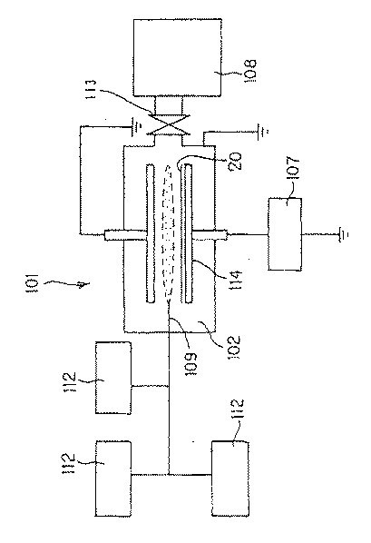
図4は、横軸に回折角2θ(°)を、縦軸に回折強度を示した図である。図4によれば、実施例1及び比較例1、2のいずれの高分子樹脂フィルムにも、回折角が26°付近と56°付近にピークがあり、これら2つのピークについては全ての高分子フィルムに共通していることから、これらはPEN樹脂に帰因するピークであることが明らかである。しかしながら、本発明の実施例1の高分子樹脂フィルムについては、上記2つのピーク以外に、12°付近にピークがあり(図4中のAの部分)、このピークは実施例1の高分子樹脂に含有されている鉱石としてのカオリナイトに帰因するものであることが分かった。
【0082】
次に、上記の実施例1及び比較例1、2の高分子樹脂フィルムを用いて、本発明の実施例及び比較例としてのガスバリアフィルムを製造した。
【0083】
(実施例2)
図5に示す平行平板型プラズマCVD装置(アネルバ製、PED−401)101を用い、基材20としては、上記実施例1の高分子樹脂フィルムを用いた。プラズマCVD装置101のチャンバー102内の下部電極114側に装着した。次に、CVD装置101のチャンバー102内を、油回転ポンプおよびターボ分子ポンプにより、到達真空度3.0×10⁻⁵Torr(4.0×10⁻³Pa)まで減圧した。また、原料ガス112として、テトラメトキシシラン(TMOS)ガス(信越化学工業(株)、KBM−04)、および酸素ガス(太陽東洋酸素(株)、純度99.9999%以上)、ヘリウムガス(太陽東洋酸素(株)、純度99.999%以上)を準備した。
【0084】
次に、下部電極114に90kHzの周波数を有する電力(投入電力:300W)を印加した。そして、チャンバー102内の電極近傍に設けられたガス導入口109から、HMDSOガスを1sccm、酸素ガスを12sccm、ヘリウムガスを30sccm導入し、真空ポンプ108とチャンバー102との間にあるバルブ113の開閉度を制御することにより、成層チャンバー内圧力を0.25Torr(33.325Pa)に保ち、基材フィルム20上にガスバリア層としての酸化珪素層の成層を行った。ここで、sccmは、standard cubic cm per minuteの略である。層厚が100nmになるまで成層を行い、実施例2のガスバリアフィルムを得た。
【0085】
(比較例3)
基材20として、上記比較例1の高分子樹脂フィルムを用いた以外は、上記実施例2と同様にして比較例4のガスバリアフィルムを得た。
【0086】
(比較例4)
基材20として、上記比較例1の高分子樹脂フィルムを用いた以外は、上記実施例1と同様にして比較例1のガスバリアフィルムを得た。
【0087】
(ガスバリア性試験の結果)
以下の表2は、上記実施例2及び比較例3、4のガスバリアフィルムについて酸素透過率(OTR)試験と水蒸気透過率(WVTR)試験の結果を示したものである。なお、酸素透過率は、酸素ガス透過率測定装置(MOCON社製:OX−TRAN 2/20)を用いて測定した値であり、水蒸気透過率は水蒸気透過率測定装置(MOCON社製:PERMATRAN−W 3/31)を用い、37.8℃、100%Rhの条件で測定した値である。
【0088】
【表2】
表2からも明らかなように、実施例1のガスバリアフィルムは酸素透過率が0.2cc/m2/dayであり、水蒸気透過率が0.08g/m2/dayであり、優れたガスバリア性を有していることが分かった。
【0090】
一方、比較例1のガスバリアフィルムは、酸素透過率は0.2cc/m2/dayであり良好であったが、水蒸気透過率が0.50g/m2/dayであり、本発明の実施例と比べ水蒸気透過率において劣っていることが分かった。また比較例2のガスバリアフィルムは、酸素透過率が0.4cc/m2/dayであり、水蒸気透過率が0.50g/m2/dayであり、本発明の実施例に比べて酸素透過率および水蒸気透過率のどちらについても劣っていることが分かった。
【0091】
【発明の効果】
本発明の高分子樹脂フィルムによれば、本発明の高分子樹脂フィルムを基材として用い、その片面又は両面に蒸着法によりガスバリア層を形成することによってガスバリアフィルムを製造した場合、ガスバリア層の酸素透過率、及び水蒸気透過率を従来のそれよりも小さくすること、つまり、ガスバリアフィルムのガスバリア性を向上することができる。
【図面の簡単な説明】
【図1】本発明の高分子樹脂フィルムの一例を示す断面構成図である。
【図2】本発明のガスバリアフィルムの一例を示す断面構成図である。
【図3】本発明のガスバリアフィルムの他の一例を示す断面構成図である。
【図4】X線回折の結果を示す図である。
【図5】平行平板型プラズマCVD装置の概略断面図である。
【符号の説明】
1 高分子樹脂フィルム
2 フィルム本体部分
3 鉱物
10 ガスバリアフィルム
11 ガスバリア層
12 撥水層
101 平行平板型プラズマCVD装置[0001]
BACKGROUND OF THE INVENTION
The present invention relates to a polymer resin film used as a base material of a gas barrier film mainly used as a packaging material for foods and pharmaceuticals and packaging materials for electronic devices and the like, and a gas barrier film using the same.
[0002]
[Prior art]
Gas barrier films are mainly used as packaging materials for foods and pharmaceuticals in order to prevent the effects of oxygen and water vapor that cause the quality of the contents to change, and (b) liquid crystal display panels and EL An element formed on a display panel or the like is used as a packaging material for an electronic device or the like in order to avoid performance deterioration due to contact with water vapor. A gas barrier film uses a polymer resin film as a base material, and a film having a gas barrier property is bonded to one or both surfaces of the polymer resin, or a gas barrier layer having a gas barrier property is wet-layered or dry-layered. Conventionally known.
[0003]
[Problems to be solved by the invention]
However, the conventional gas barrier film is 2 cc / m 2 / Day about oxygen transmission rate (OTR), 2g / m 2 It has only a water vapor transmission rate (WVTR) of about / day, and is still insufficient when used for applications having higher gas barrier properties, for example, for sealing organic EL.
[0004]
This invention is made | formed in view of the said problem, and makes it a subject to provide the gas barrier film which has the gas barrier property which was extremely excellent compared with the conventional gas barrier film.
[0005]
[Means for Solving the Problems]
In order to solve the above problems, the present invention is a polymer resin film used as a base material of a gas barrier film in which a gas barrier layer having a gas barrier property is formed by a vapor deposition method, as described in
[0006]
According to the present invention, when a gas barrier film is produced by using the polymer resin film of the present invention as a substrate and forming a gas barrier layer on one or both surfaces thereof by vapor deposition, the oxygen permeability of the gas barrier layer and water vapor The transmittance can be made smaller than that of the conventional one, that is, the gas barrier property of the gas barrier film can be improved.
[0007]
The reason why the performance of the gas barrier film is improved by using the polymer resin film of the present invention as a substrate is difficult to explain academically or theoretically. However, it can be considered that the reason is that the gas barrier layer formed by vapor deposition on one side or both sides of the polymer resin film of the present invention is formed as a dense layer compared to the conventional gas barrier layer. That is, the polymer resin film of the present invention is characterized in that a mineral is contained on the surface thereof, but a metal is present in this mineral, and therefore a gas barrier layer is formed by a vapor deposition method. When trying to form, the mineral (especially metal) on the surface of the polymer resin film acts as a “core” for the gas barrier layer to deposit on the polymer resin film surface and grow into a layer. Can be considered. Further, when the gas barrier layer is formed by vapor deposition, a high voltage atmosphere is used to evaporate the raw material of the gas barrier layer, but the mineral present on the surface of the polymer resin of the present invention has an insulating property. As a result, the discharge voltage is increased, and the raw material of the evaporated gas barrier layer is strongly struck against the surface of the polymer resin film as the base material, and as a result, a dense layer is formed. You can also.
[0008]
In order to solve the above problems, the present invention provides the polymer resin film according to
[0009]
According to the present invention, in the polymer resin film according to
[0010]
Furthermore, in order to solve the above-mentioned object, the present invention provides the polymer resin film according to
[0011]
According to the present invention, the mineral is any one of kaolinite, alunite, sericite, and montmorillonite. Is relatively easy to obtain and easy to handle.
[0012]
Further, in the present invention, as described in claim 4, the polymer resin film according to any one of
[0013]
According to the present invention, the polymer resin film of the present invention can actually be used as a base material for a gas barrier film, whereby a gas barrier film having excellent gas barrier properties can be obtained for the reasons described above.
[0014]
DETAILED DESCRIPTION OF THE INVENTION
FIG. 1 is a cross-sectional configuration diagram showing an example of the polymer resin film of the present invention.
[0015]
As shown in FIG. 1, the
[0016]
Hereinafter, the present invention will be described with respect to the
[0017]
[1] Film body
In the present invention, the
[0018]
In particular,
-Homopolymers such as ethylene, polypropylene, butene or polyolefin (PO) resin films such as copolymers or copolymers,
-Amorphous polyolefin resin (APO) film such as cyclic polyolefin,
Polyester resin films such as polyethylene terephthalate (PET) and
-Polyamide (PA) resin film such as nylon 6,
-Polyvinyl alcohol resin films such as polyvinyl alcohol (PVA) resin, ethylene-vinyl alcohol copolymer (EVOH),
・ Polyimide (PI) resin film,
・ Polyetherimide (PEI) resin film,
・ Polysulfone (PS) resin film,
・ Polyethersulfone (PES) resin film,
・ Polyetheretherketone (PEEK) resin film,
・ Polycarbonate (PC) resin film,
-Polyvinyl butyrate (PVB) resin film,
・ Polyarylate (PAR) resin film,
・ Ethylene-tetrafluoroethylene copolymer (ETFE), ethylene trifluoride chloride (PFA), tetrafluoroethylene-perfluoroalkyl vinyl ether copolymer (FEP), vinylidene fluoride (PVDF), vinyl fluoride ( PVF), fluorine-based resin films such as perfluoroethylene-perfluoropropylene-perfluorovinyl ether copolymer (EPA),
Etc. can be used.
[0019]
In addition to the resin films listed above, a resin composition comprising an acrylate compound having a radical-reactive unsaturated compound, a resin composition comprising the acrylate compound and a mercapto compound having a thiol group, epoxy acrylate, urethane It is also possible to use a film such as a photocurable resin such as a resin composition in which an oligomer such as acrylate, polyester acrylate, or polyether acrylate is dissolved in a polyfunctional acrylate monomer, and a mixture thereof. Furthermore, it is also possible to use a film obtained by laminating one or more of these resin films by means such as laminating or coating. The
[0020]
On the surface of the
[0021]
[2] Minerals
In the
(1) In the case where the
(2) A role of increasing the discharge voltage when the
[0022]
The reason for fulfilling the role of (1) above is that since minerals usually contain metals, the presence of the metal-containing minerals on the surface of the
[0023]
The
[0024]
The size of the
[0025]
The interval between
[0026]
Specifically, the
[0027]
In the present invention, two or more of kaolinite, alunite, sericite and montmorillonite may be contained.
[0028]
The production method of the
[0029]
Next, a gas barrier film characterized by using the
[0030]
FIG. 2 is a schematic cross-sectional view of a
[0031]
As shown in FIG. 2, the
[0032]
In the
[0033]
As the types of layers when the
[0034]
On the other hand, examples of the layer type in the case of making it opaque include aluminum, silicon and the like, and all metal thin layers can be used as the gas barrier layer of the present invention.
[0035]
In the present invention, there are many applications in which transparency is required for the gas barrier film, for example, when used as a packaging material. Therefore, in the present invention, the gas barrier layer is preferably transparent, and specifically, a metal oxide vapor deposition layer as described above is preferable.
[0036]
In the present invention, among various gas barrier layers 11, a silicon oxide layer is preferably used as the gas barrier layer, and particularly comprises a component ratio of 170 to 200 O atoms and 30 or less C atoms to 100 Si atoms. , 1055-1065cm -1 A silicon oxide layer having IR absorption based on Si—O—Si stretching vibration is preferred. This is because by having such characteristics, the gas barrier property is improved, and the gas barrier property as a gas barrier film when a water repellent layer is formed on the surface can be made extremely high.
[0037]
Further, at this time, it is more preferable to form so as to have a refractive index of 1.45 to 1.48 (λ = 633 nm). This is because a gas barrier film including a silicon oxide layer having such characteristics can exhibit extremely excellent gas barrier properties.
[0038]
In order to make each component ratio of Si, O, and C to be 170 to 200 O atoms and 30 or less C atoms with respect to 100 Si atoms, the flow rate ratio between the organosilicon compound gas and the oxygen gas or the organosilicon compound gas The amount of input power per unit flow rate can be adjusted and controlled within the above range. In particular, it is preferable to control so that mixing of C is suppressed. For example, by adjusting the flow rate ratio of (oxygen gas / organosilicon compound) in the range of about 3 to 50,
[0039]
A silicon oxide layer having a component composition in this range has few Si—C bonds, so
[0040]
When the O component ratio is less than 170, the flow rate ratio of (oxygen gas / organosilicon compound gas) is small (when the oxygen gas flow rate is relatively small) or the organosilicon compound gas is charged per unit flow rate. This is often seen when the power is small, and as a result, the component ratio of C increases. As a result, there are many Si-C bonds in the layer, and SiO 2 Since it is not a like homogeneous layer, oxygen permeability and water vapor permeability are increased, and sufficient gas barrier properties cannot be exhibited. Note that the number of O atoms is less than 200 stoichiometrically. When the C component ratio exceeds 30, the same conditions as when the O component ratio is less than 170, that is, when the flow rate ratio of (oxygen gas / organosilicon compound gas) is small (the oxygen gas flow rate is relatively high). Often) and when the input power per unit flow rate of the organosilicon compound gas is small, Si—C bonds remain in the layer. As a result, the Si—C bond is lost, and the oxygen permeability and the water vapor permeability are increased, so that a sufficient gas barrier property cannot be exhibited. On the other hand, the lower limit of the component ratio of C is not particularly specified, but can be specified as 10 as the lower limit value in the actual stratification process. Although it is not easy in practice to make the component ratio of C less than 10, the component ratio of C may be less than 10, SiO 2 2 A like homogeneous layer is obtained.
[0041]
In IR measurement, 1055-1065 cm -1 In order to have absorption based on Si—O—Si stretching vibration between the silicon oxide layer and the
[0042]
IR absorption is measured and evaluated with an infrared spectrophotometer for IR measurement. Preferably, an infrared absorption spectrum is measured by attaching an ATR (multiple reflection) measuring device to the infrared spectrophotometer. At this time, it is preferable to use a germanium crystal for the prism and measure at an incident angle of 45 degrees.
[0043]
If there is no IR absorption in this range, the flow rate ratio of (oxygen gas / organosilicon compound gas) is small (the oxygen gas flow rate is relatively small) or the organosilicon compound gas]
This is often seen when the input power per unit flow rate is small, and as a result, the component ratio of C increases. As a result, it has Si—C bonds in the layer, and
[0044]
In order to adjust the refractive index of the silicon oxide layer to 1.45 to 1.48, the flow rate ratio between the organosilicon compound gas and the oxygen gas, the magnitude of the input power per unit flow rate of the organosilicon compound gas, and the like are adjusted. Can be controlled within the above range. For example, the flow rate ratio of (oxygen gas / organosilicon compound gas) can be adjusted and controlled in the range of about 3-50. The upper limit of the flow rate ratio is defined for convenience, and there is no particular problem even if it exceeds 50. A silicon oxide layer having a refractive index in this range is a dense, low-
[0045]
When the refractive index is less than 1.45, the flow rate ratio between the organosilicon compound gas and the oxygen gas is outside the above range, or the input power per unit flow rate of the organosilicon compound gas is small, and the density is low and sparse. This is often seen when a silicon oxide layer is obtained, and the layered silicon oxide layer becomes sparse, so that the oxygen permeability and the water vapor permeability are increased, and a sufficient gas barrier property cannot be exhibited. On the other hand, when the refractive index exceeds 1.48, it is often seen when the flow ratio of the organosilicon compound gas and the oxygen gas is out of the above range, or when impurities such as C (carbon) are mixed, The laminated silicon oxide layer becomes sparse, and the oxygen permeability and the water vapor permeability are increased, so that a sufficient gas barrier property cannot be exhibited.
[0046]
The gas barrier film in which the silicon oxide layer having the above-described characteristics is formed with a thin thickness of 5 to 300 nm can exhibit excellent gas barrier properties, and cracks are not easily generated in the silicon oxide layer. When the thickness of the silicon oxide layer is less than 5 nm, the silicon oxide layer may not be able to cover the entire surface of the substrate, and the gas barrier property cannot be improved. On the other hand, if the thickness of the silicon oxide layer exceeds 300 nm, cracks are likely to occur, transparency and appearance are deteriorated, curl of the film is increased, and further, mass production is difficult and productivity is reduced, resulting in cost reduction. Inconveniences such as an increase in the value are likely to occur.
[0047]
In the
[0048]
For example, as shown in FIG. 2, a water-
[0049]
The
[0050]
Here, the method for measuring the contact angle with water is a value obtained using a contact angle measuring device (model number CA-Z) manufactured by Kyowa Interface Chemical Co., Ltd. In other words, on the surface of the object to be measured, a single drop (fixed amount) is dropped, and after a certain period of time, the shape of the water drop is observed using a microscope or a CCD camera, and the method for physically obtaining the contact angle is used. Let the contact angle with water measured by this method be the contact angle with water in the present invention.
[0051]
Such a
[0052]
However, in the present invention, the
[0053]
In consideration of the point that a conventional water-repellent material can be used as it is, and the point that a material that cannot be applied to the plasma CVD method or the sputtering method can be used, the above-described coating for forming a water-repellent layer is used. It may be a water repellent layer formed by a method of applying a working liquid or a method of melt-applying a thermoplastic resin.
[0054]
The substance constituting such a water-repellent layer differs greatly depending on the method for forming the water-repellent layer as described above. Specifically, examples of the material for forming the water-repellent layer by vapor deposition include an organic layer having a metal skeleton and having a methyl group, an organic layer having only CH, and a layer containing F. . Hereinafter, each layer will be described.
[0055]
1. Organic layer consisting of a metal skeleton and having a methyl group
Examples of the metal skeleton of such an organic layer include Si and Al. Specific materials include Si x (CH Three ) y Or (SiO) x (CH Three ) y Or a polymerized layer using a plasma CVD method or a plasma polymerization method.
[0056]
2. Organic layer composed only of CH
Specifically, a hydrocarbon material or a polymerization layer thereof can be used. As a method for producing such a layer, a plasma CVD method (plasma polymerization method) may be used, or a polyolefin material such as polyethylene may be deposited by a PVD method.
[0057]
3. Layer containing F
As the layer containing F, for example, Si x C y F, an organic silicon fluoride material or a polymerized layer thereof, Si x F y Or a polymerized layer thereof, or C x F y Or a polymerized layer thereof, or the like.
[0058]
In addition, as a material constituting the water repellent layer in the case of applying the water repellent layer forming coating liquid as described above, a fluorine-based organic material, a polyolefin-based organic material, a methyl group-containing silicon material, or the like can be given. be able to.
[0059]
Furthermore, examples of the material for forming the water repellent layer by melting and applying the thermoplastic resin include olefin resins such as polyethylene resins, polypropylene resins, and cyclic polyolefin resins.
[0060]
In addition, for example, a polyolefin film such as a fluororesin film or a polyethylene film can be bonded by a dry lamination method using an adhesive.
[0061]
In the present invention, among the materials constituting the water repellent layer described above, materials used when formed by vapor deposition are preferred, and particularly preferred materials include hexamethyldisiloxane, tetramethyldisiloxane, and tetramethylsilane. , C 2 H 2 , C 2 H Four , CH Four , C 2 H 6 , CF Four , C 2 F 2 , C 2 F Four , C 2 F 6 , Polyethylene resin, cyclic polyolefin resin, and the like.
[0062]
The suitable layer thickness in such a water-repellent layer varies greatly depending on the production method. Specifically, the preferred layer thickness when the water repellent layer is formed by vapor deposition is preferably in the range of 1 nm to 1000 nm, particularly in the range of 5 nm to 100 nm. On the other hand, preferred layer thicknesses in other methods, that is, a method of forming by applying a water repellent layer forming coating liquid, a method of applying by melting a thermoplastic resin, etc. are in the range of 1 μm to 100 μm. In particular, it is preferably in the range of 1 μm to 50 μm.
[0063]
When the thickness of the water repellent layer is smaller than the above range, it is not preferable because the function as the water repellent layer may not be exhibited, for example, a portion where the water repellent layer is not formed may occur. Even if the thickness is increased, it does not affect the water repellency, which may cause a problem in terms of cost.
[0064]
Moreover, the gas barrier film of the present invention may be required to have transparency depending on the application. Therefore, the water repellent layer described above is also preferably transparent.
[0065]
FIG. 3 is a view showing another embodiment of the gas barrier film of the present invention. As shown in FIG. 3, the
[0066]
In the present invention, the stack of the
[0067]
Such a
[0068]
Next, the manufacturing method of the
[0069]
As the vapor deposition method for producing the
[0070]
The plasma CVD method is a method in which a raw material gas at a constant pressure is discharged into a plasma state, and a chemical reaction on the substrate surface is promoted by active particles generated in the plasma. This plasma CVD method has an advantage that the kind and physical properties of the layer obtained can be controlled by the kind and flow rate of the source gas, the stratification pressure, the input power, and the like.
[0071]
When a silicon oxide layer is used as the
[0072]
In this case, as the organosilicon compound gas, hexamethyldisiloxane (HMDSO), 1,1,3,3-tetramethyldisiloxane (TMDSO), vinyltrimethoxysilane, vinyltrimethylsilane, tetramethoxysilane (TMOS), Methyltrimethoxysilane, dimethyldimethoxysilane, trimethylmethoxysilane, hexamethyldisilazane can be preferably used, and one or more conventionally known ones such as tetramethyldisiloxane and normal methyltrimethoxysilane are used. be able to. As the carrier gas, helium gas or argon gas can be appropriately used.
[0073]
Further, the
[0074]
【Example】
The present invention will be described more specifically with reference to the following examples and comparative examples.
[0075]
First, the following were manufactured and prepared as examples and comparative examples of the present invention.
[0076]
(Example 1)
PEN resin is used as the polymer resin, and kaolinite having a particle size of 0.5 to 2 μm is contained therein so that the interval is 20 to 100 μm, and is manufactured into a sheet using a biaxially stretched film manufacturing apparatus. The polymer resin film of Example 1 was obtained.
[0077]
(Comparative Example 2)
A commercially available sheet-like PEN film (manufactured by Teijin DuPont Films, Inc., thickness 100 μm) was used as the polymer resin film of Comparative Example 2.
[0078]
(Comparative Example 3)
A commercially available sheet-like PEN film (manufactured by Teijin DuPont Films Ltd .: K1020, thickness 100 μm)
[0079]
Next, X-ray diffraction (150 ° C., 17 hours) was performed on each of the polymer resin films. For X-ray diffraction, RINT2000 (manufactured by Rigaku Corporation) was used. Table 1 shows details of measurement conditions, and FIG. 4 shows diffraction results.
[0080]
[Table 1]
FIG. 4 shows the diffraction angle 2θ (°) on the horizontal axis and the diffraction intensity on the vertical axis. According to FIG. 4, the polymer resin films of Example 1 and Comparative Examples 1 and 2 have peaks at diffraction angles near 26 ° and 56 °. Since they are common to films, it is clear that these are peaks attributed to PEN resin. However, the polymer resin film of Example 1 of the present invention has a peak near 12 ° in addition to the above two peaks (portion A in FIG. 4), and this peak is the polymer resin of Example 1. It was found to be attributed to kaolinite as an ore contained in.
[0082]
Next, using the polymer resin films of Example 1 and Comparative Examples 1 and 2, gas barrier films as Examples and Comparative Examples of the present invention were produced.
[0083]
(Example 2)
A parallel plate type plasma CVD apparatus (manufactured by Anelva, PED-401) 101 shown in FIG. 5 was used, and the polymer resin film of Example 1 was used as the
[0084]
Next, power having a frequency of 90 kHz (input power: 300 W) was applied to the
[0085]
(Comparative Example 3)
A gas barrier film of Comparative Example 4 was obtained in the same manner as in Example 2 except that the polymer resin film of Comparative Example 1 was used as the
[0086]
(Comparative Example 4)
A gas barrier film of Comparative Example 1 was obtained in the same manner as in Example 1 except that the polymer resin film of Comparative Example 1 was used as the
[0087]
(Results of gas barrier property test)
Table 2 below shows the results of the oxygen transmission rate (OTR) test and the water vapor transmission rate (WVTR) test for the gas barrier films of Example 2 and Comparative Examples 3 and 4. The oxygen permeability is a value measured using an oxygen gas permeability measuring device (manufactured by MOCON: OX-
[0088]
[Table 2]
As is clear from Table 2, the gas barrier film of Example 1 has an oxygen permeability of 0.2 cc / m. 2 / Day, and water vapor transmission rate is 0.08 g / m. 2 / Day, and it was found to have excellent gas barrier properties.
[0090]
On the other hand, the gas barrier film of Comparative Example 1 has an oxygen permeability of 0.2 cc / m. 2 / Day was good, but the water vapor transmission rate was 0.50 g / m. 2 It was found that the water vapor transmission rate was inferior to that of the example of the present invention. The gas barrier film of Comparative Example 2 has an oxygen permeability of 0.4 cc / m. 2 / Day, and water vapor transmission rate is 0.50 g / m. 2 / Day, and it was found that both the oxygen transmission rate and the water vapor transmission rate were inferior to those of the examples of the present invention.
[0091]
【The invention's effect】
According to the polymer resin film of the present invention, when the gas barrier film is produced by using the polymer resin film of the present invention as a base material and forming a gas barrier layer on one or both surfaces thereof by vapor deposition, oxygen in the gas barrier layer The permeability and water vapor permeability can be made smaller than that of the conventional one, that is, the gas barrier property of the gas barrier film can be improved.
[Brief description of the drawings]
FIG. 1 is a cross-sectional configuration diagram showing an example of a polymer resin film of the present invention.
FIG. 2 is a cross-sectional configuration diagram showing an example of a gas barrier film of the present invention.
FIG. 3 is a cross-sectional configuration diagram showing another example of the gas barrier film of the present invention.
FIG. 4 is a diagram showing the results of X-ray diffraction.
FIG. 5 is a schematic sectional view of a parallel plate type plasma CVD apparatus.
[Explanation of symbols]
1 Polymer resin film
2 Film body
3 Minerals
10 Gas barrier film
11 Gas barrier layer
12 Water repellent layer
101 Parallel plate type plasma CVD equipment
Claims (2)
前記高分子樹脂フィルムの片面又は両面に蒸着法により形成されるガスバリア性を有するガスバリア層と、からなるガスバリアフィルムであって、 A gas barrier film having a gas barrier property formed by vapor deposition on one or both sides of the polymer resin film,
前記高分子樹脂フィルムは、フィルム本体部分と、その表面に含有せしめられた鉱物と、から構成されており、当該鉱物は粒子状であり、その粒径は0.5〜2μmであって、隣り合う鉱物同士の間隔は20〜100μmであり、 The polymer resin film is composed of a film main body portion and a mineral contained on the surface thereof, and the mineral is in the form of particles and has a particle size of 0.5 to 2 μm and adjacent to the mineral body. The interval between the matching minerals is 20-100 μm,
また、前記ガスバリア層は、酸化アルミニウム、酸化亜鉛、酸化アンチモン、酸化インジウム、酸化セリウム、酸化カルシウム、酸化カドミウム、酸化銀、酸化金、酸化クロム、酸化珪素、酸化コバルト、酸化ジルコニウム、酸化スズ、酸化チタン、酸化鉄、酸化銅、酸化ニッケル、酸化白金、酸化パラジウム、酸化ビスマス、酸化マグネシウム、酸化マンガン、酸化モリブデン、酸化バナジウム、酸化バリウム、又はITO(インジウム−スズ酸化物)の何れかからなる透明な層であることを特徴とする透明ガスバリアフィルム。 The gas barrier layer is made of aluminum oxide, zinc oxide, antimony oxide, indium oxide, cerium oxide, calcium oxide, cadmium oxide, silver oxide, gold oxide, chromium oxide, silicon oxide, cobalt oxide, zirconium oxide, tin oxide, oxide Transparent made of titanium, iron oxide, copper oxide, nickel oxide, platinum oxide, palladium oxide, bismuth oxide, magnesium oxide, manganese oxide, molybdenum oxide, vanadium oxide, barium oxide, or ITO (indium-tin oxide) A transparent gas barrier film, characterized in that the layer is a transparent layer.
Priority Applications (1)
| Application Number | Priority Date | Filing Date | Title |
|---|---|---|---|
| JP2001286753A JP4153185B2 (en) | 2001-09-20 | 2001-09-20 | Polymer resin film and gas barrier film using the same |
Applications Claiming Priority (1)
| Application Number | Priority Date | Filing Date | Title |
|---|---|---|---|
| JP2001286753A JP4153185B2 (en) | 2001-09-20 | 2001-09-20 | Polymer resin film and gas barrier film using the same |
Publications (2)
| Publication Number | Publication Date |
|---|---|
| JP2003094564A JP2003094564A (en) | 2003-04-03 |
| JP4153185B2 true JP4153185B2 (en) | 2008-09-17 |
Family
ID=19109675
Family Applications (1)
| Application Number | Title | Priority Date | Filing Date |
|---|---|---|---|
| JP2001286753A Expired - Fee Related JP4153185B2 (en) | 2001-09-20 | 2001-09-20 | Polymer resin film and gas barrier film using the same |
Country Status (1)
| Country | Link |
|---|---|
| JP (1) | JP4153185B2 (en) |
Families Citing this family (4)
| Publication number | Priority date | Publication date | Assignee | Title |
|---|---|---|---|---|
| JP2007144977A (en) * | 2005-10-25 | 2007-06-14 | Toppan Printing Co Ltd | Transparent barrier film and method for producing the same |
| KR101707162B1 (en) * | 2015-07-01 | 2017-02-16 | 고려대학교 산학협력단 | A method for fabricating a flexible gas barrier film with a low water vapour transmissibility |
| TW202516202A (en) * | 2023-10-10 | 2025-04-16 | 日商日東電工股份有限公司 | Anti-reflection film and method for manufacturing the same |
| JP7758816B1 (en) * | 2024-09-10 | 2025-10-22 | 日東電工株式会社 | Anti-reflection film and method for producing the same |
-
2001
- 2001-09-20 JP JP2001286753A patent/JP4153185B2/en not_active Expired - Fee Related
Also Published As
| Publication number | Publication date |
|---|---|
| JP2003094564A (en) | 2003-04-03 |
Similar Documents
| Publication | Publication Date | Title |
|---|---|---|
| JP4191668B2 (en) | Laminate | |
| JP5394867B2 (en) | Gas barrier film and gas barrier film | |
| JP3734724B2 (en) | Gas barrier film | |
| JP5267712B2 (en) | Method for producing transparent gas barrier film and organic electroluminescence device | |
| JP4464155B2 (en) | Barrier film | |
| CN111511814B (en) | Organic-inorganic hybrid film | |
| JP2002192646A (en) | Gas barrier film | |
| JP2018020540A (en) | Barrier film | |
| JP2009274251A (en) | Transparent barrier film and its manufacturing method | |
| JP2003340971A (en) | Gas barrier plastic film | |
| JP2005256061A (en) | Laminated body | |
| JP4153185B2 (en) | Polymer resin film and gas barrier film using the same | |
| JP5751027B2 (en) | Transparent conductive film | |
| JP7061284B2 (en) | Barrier film | |
| JP5598080B2 (en) | Method for producing gas barrier sheet | |
| CN108137832B (en) | Multilayer Barrier Stack | |
| JP3840080B2 (en) | Gas barrier film | |
| JP4046155B2 (en) | Gas barrier film | |
| JP2006096046A (en) | Gas barrier film | |
| JP4028339B2 (en) | Method for forming laminate with gas barrier film | |
| JP2005171304A (en) | Barrier film manufacturing method | |
| WO2009131136A1 (en) | Heat insulation resin base and architectural member using the same | |
| JP6846008B2 (en) | Barrier film manufacturing method | |
| WO2017054189A1 (en) | Multilayer barrier stack | |
| JP4765216B2 (en) | Transparent gas barrier laminated film |
Legal Events
| Date | Code | Title | Description |
|---|---|---|---|
| A621 | Written request for application examination |
Free format text: JAPANESE INTERMEDIATE CODE: A621 Effective date: 20040909 |
|
| A977 | Report on retrieval |
Free format text: JAPANESE INTERMEDIATE CODE: A971007 Effective date: 20060818 |
|
| A131 | Notification of reasons for refusal |
Free format text: JAPANESE INTERMEDIATE CODE: A131 Effective date: 20070116 |
|
| A521 | Written amendment |
Free format text: JAPANESE INTERMEDIATE CODE: A523 Effective date: 20070316 |
|
| TRDD | Decision of grant or rejection written | ||
| A01 | Written decision to grant a patent or to grant a registration (utility model) |
Free format text: JAPANESE INTERMEDIATE CODE: A01 Effective date: 20080701 |
|
| A01 | Written decision to grant a patent or to grant a registration (utility model) |
Free format text: JAPANESE INTERMEDIATE CODE: A01 |
|
| A61 | First payment of annual fees (during grant procedure) |
Free format text: JAPANESE INTERMEDIATE CODE: A61 Effective date: 20080703 |
|
| R150 | Certificate of patent or registration of utility model |
Free format text: JAPANESE INTERMEDIATE CODE: R150 |
|
| FPAY | Renewal fee payment (event date is renewal date of database) |
Free format text: PAYMENT UNTIL: 20110711 Year of fee payment: 3 |
|
| FPAY | Renewal fee payment (event date is renewal date of database) |
Free format text: PAYMENT UNTIL: 20120711 Year of fee payment: 4 |
|
| FPAY | Renewal fee payment (event date is renewal date of database) |
Free format text: PAYMENT UNTIL: 20120711 Year of fee payment: 4 |
|
| FPAY | Renewal fee payment (event date is renewal date of database) |
Free format text: PAYMENT UNTIL: 20130711 Year of fee payment: 5 |
|
| LAPS | Cancellation because of no payment of annual fees | ||
| RD02 | Notification of acceptance of power of attorney |
Free format text: JAPANESE INTERMEDIATE CODE: R3D02 |