JP4136313B2 - Tracheostomy tube - Google Patents
Tracheostomy tube Download PDFInfo
- Publication number
- JP4136313B2 JP4136313B2 JP2000544389A JP2000544389A JP4136313B2 JP 4136313 B2 JP4136313 B2 JP 4136313B2 JP 2000544389 A JP2000544389 A JP 2000544389A JP 2000544389 A JP2000544389 A JP 2000544389A JP 4136313 B2 JP4136313 B2 JP 4136313B2
- Authority
- JP
- Japan
- Prior art keywords
- collar
- cannula
- tab
- outer cannula
- inner cannula
- Prior art date
- Legal status (The legal status is an assumption and is not a legal conclusion. Google has not performed a legal analysis and makes no representation as to the accuracy of the status listed.)
- Expired - Fee Related
Links
- 241001631457 Cannula Species 0.000 description 7
- 230000029058 respiratory gaseous exchange Effects 0.000 description 5
- 210000003437 trachea Anatomy 0.000 description 5
- 238000004140 cleaning Methods 0.000 description 2
- 238000003780 insertion Methods 0.000 description 2
- 230000037431 insertion Effects 0.000 description 2
- 230000003993 interaction Effects 0.000 description 2
- 230000007246 mechanism Effects 0.000 description 2
- 230000002093 peripheral effect Effects 0.000 description 2
- 230000001105 regulatory effect Effects 0.000 description 2
- 230000002269 spontaneous effect Effects 0.000 description 2
- 230000002618 waking effect Effects 0.000 description 2
- 206010011224 Cough Diseases 0.000 description 1
- 230000001419 dependent effect Effects 0.000 description 1
- 238000004519 manufacturing process Methods 0.000 description 1
- 238000000034 method Methods 0.000 description 1
- 238000012986 modification Methods 0.000 description 1
- 230000004048 modification Effects 0.000 description 1
- 238000000465 moulding Methods 0.000 description 1
- 230000000241 respiratory effect Effects 0.000 description 1
- 230000000284 resting effect Effects 0.000 description 1
- 230000004622 sleep time Effects 0.000 description 1
Images


Classifications
-
- A—HUMAN NECESSITIES
- A61—MEDICAL OR VETERINARY SCIENCE; HYGIENE
- A61M—DEVICES FOR INTRODUCING MEDIA INTO, OR ONTO, THE BODY; DEVICES FOR TRANSDUCING BODY MEDIA OR FOR TAKING MEDIA FROM THE BODY; DEVICES FOR PRODUCING OR ENDING SLEEP OR STUPOR
- A61M16/00—Devices for influencing the respiratory system of patients by gas treatment, e.g. ventilators; Tracheal tubes
- A61M16/04—Tracheal tubes
- A61M16/0465—Tracheostomy tubes; Devices for performing a tracheostomy; Accessories therefor, e.g. masks, filters
-
- A—HUMAN NECESSITIES
- A61—MEDICAL OR VETERINARY SCIENCE; HYGIENE
- A61M—DEVICES FOR INTRODUCING MEDIA INTO, OR ONTO, THE BODY; DEVICES FOR TRANSDUCING BODY MEDIA OR FOR TAKING MEDIA FROM THE BODY; DEVICES FOR PRODUCING OR ENDING SLEEP OR STUPOR
- A61M16/00—Devices for influencing the respiratory system of patients by gas treatment, e.g. ventilators; Tracheal tubes
- A61M16/04—Tracheal tubes
- A61M16/0402—Special features for tracheal tubes not otherwise provided for
- A61M16/0427—Special features for tracheal tubes not otherwise provided for with removable and re-insertable liner tubes, e.g. for cleaning
-
- A—HUMAN NECESSITIES
- A61—MEDICAL OR VETERINARY SCIENCE; HYGIENE
- A61M—DEVICES FOR INTRODUCING MEDIA INTO, OR ONTO, THE BODY; DEVICES FOR TRANSDUCING BODY MEDIA OR FOR TAKING MEDIA FROM THE BODY; DEVICES FOR PRODUCING OR ENDING SLEEP OR STUPOR
- A61M16/00—Devices for influencing the respiratory system of patients by gas treatment, e.g. ventilators; Tracheal tubes
- A61M16/04—Tracheal tubes
- A61M16/0488—Mouthpieces; Means for guiding, securing or introducing the tubes
- A61M16/0497—Tube stabilizer
-
- Y—GENERAL TAGGING OF NEW TECHNOLOGICAL DEVELOPMENTS; GENERAL TAGGING OF CROSS-SECTIONAL TECHNOLOGIES SPANNING OVER SEVERAL SECTIONS OF THE IPC; TECHNICAL SUBJECTS COVERED BY FORMER USPC CROSS-REFERENCE ART COLLECTIONS [XRACs] AND DIGESTS
- Y10—TECHNICAL SUBJECTS COVERED BY FORMER USPC
- Y10S—TECHNICAL SUBJECTS COVERED BY FORMER USPC CROSS-REFERENCE ART COLLECTIONS [XRACs] AND DIGESTS
- Y10S128/00—Surgery
- Y10S128/912—Connections and closures for tubes delivering fluids to or from the body
Landscapes
- Health & Medical Sciences (AREA)
- Pulmonology (AREA)
- Emergency Medicine (AREA)
- Engineering & Computer Science (AREA)
- Anesthesiology (AREA)
- Biomedical Technology (AREA)
- Heart & Thoracic Surgery (AREA)
- Hematology (AREA)
- Life Sciences & Earth Sciences (AREA)
- Animal Behavior & Ethology (AREA)
- General Health & Medical Sciences (AREA)
- Public Health (AREA)
- Veterinary Medicine (AREA)
- Surgical Instruments (AREA)
- Prostheses (AREA)
- Details Of Spanners, Wrenches, And Screw Drivers And Accessories (AREA)
- Infusion, Injection, And Reservoir Apparatuses (AREA)
Description
【0001】
【発明の分野】
本発明は気管切開管、特に内側カニューレを気管切開管の外側カニューレに組み立てる/外側カニューレから分解するのに必要な力を調節するための構成要素をもつ気管切開管に関するものである。
【0002】
【発明の背景】
気管切開管は既知である。それらは強制呼吸のために患者の気管へ至る直接の進入路を提供するため又は患者に空気通路を提供するために使用される。
【0003】
あるタイプの気管切開管は内側又は内部カニューレが挿入される外側又は外部カニューレをもつ。外側と内側のカニューレの両者を合体することによって、かかる気管切開管は患者から外側カニューレを除去する必要なしに浄化のために内側カニューレのみを除去することができ、それによって患者へ与える不快さを最小限にし、また一旦外側カニューレが患者の気管内に設置されれば、この外側カニューレを除去する必要性を最小限にする。
【0004】
内側カニューレを例えば浄化の目的で外側カニューレから除去しなければならないか、又は内側カニューレが日中の異なった時間中に患者のために使用されるとすれば、内側カニューレの外側カニューレへの番い結合がしっかりなされなければならず、同時に、内側カニューレは外側カニューレから容易に除去可能でなければならない。
【0005】
内側と外側の両カニューレをもつ先行技術の気管切開管の1つは本発明の譲受人によって販売された D.I.C. (登録商標名)気管切開管である。この場合、少なくとも1つの周囲延長部が内側カニューレの近位端に設けられていて、内側カニューレが外側カニューレ内に押し込められたときこの周囲延長部は外側カニューレのハブと一体をなす対応する周囲溝内に位置するようになる。これは本質的に1種の押し込みスナップ嵌合(push and snap fit) である。しかし、患者側の偶発的な動き、または他人によって、内側カニューレが外側カニューレから引き抜かれる可能性がある。
【0006】
もう1つの気管切開管は内側カニューレを外側カニューレに“ねじり鎖錠(twist-on lock) ”をなすことによって定着し、その場合、内側カニューレは外側カニューレ内に挿入された後、内側カニューレのハブの回転移動が外側カニューレのハブに相対的に行われて、外側カニューレのハブにある2つの内部溝と内側カニューレのハブにある2つの出っ張り間の相互作用によって内側カニューレを外側カニューレに定着する。この気管切開管の問題点は、内側と外側の両方のカニューレが成形された構成要素であるため、時にはかかる構成要素が正しい仕様で正確に成形されていないということにある。従って、例えば内側カニューレが薄過ぎる厚さに成形されたとき、それは例えば患者が咳をすると、外側カニューレから容易に解き放されることがある。他方、もし内側カニューレが厚過ぎる厚さに成形されると、内側カニューレのハブにある出っ張りと外側カニューレのハブにある内部溝間の相互作用が幾分きつくなり、その結果,医療担当者が内側カニューレを外側カニューレに番い結合しようとしたとき、外側カニューレを内側カニューレと適所において捩じり鎖錠する彼の努力は患者に過度の不快さを与える可能性がある。
【0007】
それ故、成形物製造プロセスに起因する不完全性の存在にもかかわらず、内側と外側のカニューレ間に安全な掛合を提供する気管切開管が必要とされる。更に、内側と外側のカニューレが正確に仕様書に合うよう製造されなかったとしても、かかる気管切開管の患者への挿入は不相応な量の不快さを患者に与えるべきではない。
【0008】
【発明の要約】
本発明の気管切開管は近位端と遠位端を各々もつ外側カニューレと内側カニューレを含む。外側カニューレの遠位端には膨張可能のカフがある。外側カニューレの近位端と一体の2つの対向するタブがあり又はそこにハブがあり、前記タブはお互いから離れるように延在している。これらのタブの各々は、その下側に設けられた傾斜した縁と突出部又は延長部をもつことができる。内側カニューレは外側カニューレと実質上同じ長さをもち、その中に入ることができ、又はそれと番い結合することができる。内側カニューレの遠位端と、第1の端部である近位端は外側カニューレの遠位端と近位端に夫々対応する。内側カニューレの近位端に形成されているのは回転可能のカラー又はリングである。カラーの下側には2つの対向する開口があり、その各々は外側カニューレの対向するタブの対応する1つと番い結合する予定のものである。カラーの下側は更に、各開口からカラーの約四分の一回転まで延在する内部傾斜路をもつよう形作られる。内部傾斜路の各々の端部に凹みが設けられる。
【0009】
本発明の気管切開管に重要ことは、カラー内のばねリングの如き圧力調節機構の備え付けである。このばねリングは弾性リングであり、この弾性リングは該リングの材料の厚さ又は剛性に依存して変化する弾性をもつ。かくして、適切な厚さをもつばねリングを内側カニューレのカラーに挿入することによって、内側カニューレを外側カニューレに鎖錠するのに必要とされるトルク力は、例えば彼の起きている時間と対比される患者の睡眠時間中、又は自発的呼吸と対比される人工呼吸器依存の如き種々の場合のために又は日中の特定時間のために、患者に必要とされる内側カニューレの型式に適合するよう調節されることができる。
【0010】
作業に際して、一旦外側カニューレの遠位端が患者の気管内に位置決めされかつ外側カニューレが患者の首の回りに例えばフランジ及び適切な結びひもによって固定状に留められると、内側カニューレは外側カニューレに挿入される。挿入の終了時に、内側カニューレの近位端付近のカラー又はハブは、外側カニューレのタブがその開口を介してカラー内に挿入されるよう回転可能に整列させられる。その後、時計回りの回転トルクがカラーに加えられる。これにより、カラーの下側の内部分がタブと相互作用する。カラーが予定の度数、例えば四分の一回転だけ回転した後、タブは位置決めされてカラーの下側に形成された対応する凹みで休止する。ばねリングはタブをカラーの対応する凹みに掛合させたままに保つ偏倚力を与える。ばねリングと使用される特定のカラーの厚さに依存して、内側カニューレを外側カニューレに組み立てる/外側カニューレから取り外すためのトルク量は予め決められることができる。
【0011】
それ故、本発明の目的は、内側カニューレのカラーを外側カニューレから除去するために内側カニューレのカラーにトルクを故意に加えることなしに、内側カニューレが外側カニューレに番い結合で固定されることを保証する圧力調節機構をもつ気管切開管を提供することにある。
【0012】
本発明の他の目的は、外側カニューレを組み立てる/外側カニューレから取り外すために異なったトルク量を必要とする異なった内側カニューレと共に使用するよう適用される外側カニューレをもつ気管切開管を提供することにある。
【0013】
本発明の更に他の目的は、患者が日中の異なった場合又は時間のために異なった内側カニューレを備え付けられることができるように異なった型式の内側カニューレに番い結合され得る外側カニューレをもつ気管切開管を提供することにある。
本発明の上述の目的及び利点は、本発明自体と共に添付図面に基づく以下の本発明の実施例についての説明から理解されるであろう。
【0014】
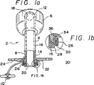
[発明の詳細な説明]
図1を参照すれば、本発明の気管切開管2は外側カニューレ4を含み,この外側カニューレにはバルーン6が取り付けられており、このバルーンは一旦外側カニューレ4が患者の気管に挿入されると、空気の漏れを防止するために患者の気管内で膨張することができる。バルーン6を膨張させる空気を供給するためにバルブ10に連結された空気ライン又は管8も図示されている。管8とバルブ10を経て空気をバルーン6に供給する方法は周知であるので、それについてこれ以上説明しない。
【0015】
図2および図3に明示される如く、外側カニューレ4は遠位端12と近位端14をもつ。図1aおよび図3には更に内側カニューレ16が示され、この内側カニューレは外側カニューレ4に挿入又は番い結合される。外側カニューレ4のように、内側カニューレ16は図に夫々18と20で示される遠位端と、第1の端部である近位端をもつ。更に図示の如く外側カニューレ4の回りにフランジ22が取り付けられており、このフランジは幾つかの孔をもち、この孔によって気管切開管2が患者にひもにより固定される。
【0016】
図1aおよび図3に最もよく示される如く、内側カニューレ16にはカラー26が取り付けられており、このカラーは図1bに拡大して示され、また図4aおよび図5aにも示されている。図1b、図4aおよび図5aに示す同じ構成要素には同じ数字が付されている。勿論、図1a、図2および図3に示す他のすべての構成要素についても同様である。
【0017】
再度カラー26を参照すれば、特に図1bの拡大図と図4aおよび図5aの断面図を見れば、カラー26は便宜上、図1bに数字26を付された主部分をもつ。この主部分26に連結されているのはスナップリング28であり、このスナップリングは、部分26と共に、内側カニューレ16の第1の端部20の回りに回転可能に取り付けられるカラーと簡単に考えることができる。このスナップリング28は図4aおよび図5aの矢印32で示す如く、カラー26に溶接される点に注目されたい。カラー26内に嵌合されるばね又は弾性リングはその厚さ又は材料に依存する弾性をもつ。ばねリング30の厚さは、外側カニューレ4の近位端又はハブから延在する図2に明示された2つのタブ34a、34bに関してカラー26を回転させるのに必要なトルク又は回転力の量に依存する。これについては後述する。当面は図4aのばねリング30の厚さが図5bに示すものより厚いことに注目されたい。
【0018】
再度図2を参照すれば、そこにはタブ34はハブ36に取り付けられるものとして示されており、このハブは外側カニューレ4の近位端14の一部又は延長部とすることができる。タブ34の1つは、ばねリング30によってそれに作用させられるようカラー26と協働して動作するものとして図1bに示されており、前記ばねリングはその面36においてタブ34に偏倚力を与えたものである。かくして、リング30の厚さに依存して、カラー26をタブ34に相対的に回転させるためにばねリング30によってタブ34に及ぼされる偏倚力に打ち勝つのに必要なトルクは変化するだろう。このことは図4a、5aに明示されている。
【0019】
図4aには、延長部26aをもつカラー26が示されている。延長部26aは、患者が睡眠状態にある間に患者が呼吸するのを助けるために呼吸機械に連結することができるので、この延長されたカラー26は、患者の睡眠時間や人工呼吸器アシスト時間の間中、患者のための内側カニューレと共に使用することができる。図4aには示していないが、内側カニューレ16の近位端20はカラー26の端部34に取り付けられることは認められるべきである。
【0020】
図4bは矢印35方向に見たカラー26の端面図である。図示の如く、タブ34と番い結合することを予定されるか又はカラー26内に入るようそれによって使用されるカラー26のための2つの対向する開口36aと36bがある。点線により示される如く、タブ34と接触するカラー26の部分は傾斜路(ramps) 30Tをなす。また、カラー26が回転矢印42によって示される方向に回されるとき、カラー26に関するタブ34の移動を案内するための、カラー26内にある2つの溝40a、40bが示されている。更に、2つの止め30a、30bがカラー26内で端部に示されている。前記止めはカラー26に関してタブ34がそれ以上移動するのを防止する。タブ34a、34bを“パーク(park)又は休止”位置に維持するよう、タブ34a、34b、又はそこから突出する若干の延長部と番い結合するために、2つの凹み42a、42bが止め30a、30bの前に夫々設けられる。タブ34が凹み42において休止状態になると、ばねリング30がタブ34に対して偏倚力を及ぼす限り、カラー26は外側カニューレ4のハブ36に番い結合されることが保証される。内側カニューレ6がカラー26に回転可能に連結される限り、内側カニューレ16は、外側カニューレ4のハブ36からそれを取り外すためにトルク力が回転矢印42の方向と反対の方向でカラー28に及ぼされない限りは、外側カニューレ4に固定状に番い結合されたままに留まるだろう。かかる取り外しトルクは勿論、ばねリング30によってタブ34に及ぼされる偏倚力の力より大きい力をもたなければならない。
【0021】
図5aは低輪郭のカラー26を示し、このカラーは、気管切開管を患者に設けるための内側カニューレ16と共に使用され、この気管切開管は、患者が、起きている時間又は自発的呼吸時間の間中に身に付けることができる。図5aの実施例のカラー26がそれに連結するための延長部をもたない事実は別として、それは、以下の1事実を除いては、図4aに示す延長カラー26と同様に動作する。即ち、そのばねリング30は図4aのカラー用のばねリング30より小さい厚さをもつ。その理由は、それに取り付けられる図4aのカラーをもつ内側カニューレを外側カニューレに組み立てる/外側カニューレから取り外すのに要求されるトルクに比して、図5aのカラー26が取り付けられる内側カニューレを組み立てる/取り外す程のトルクを必要としないことが決められているからである。詳述すれば、図4aに示すカラーは、患者が眠っている間に、気管切開管をその呼吸機械に連結するために使用することができる。患者は睡眠状態にあるため、患者が眠っている間に呼吸装置に連結されるのを保証するためと、患者によって内側カニューレが外側カニューレから偶発的に除かれるのを防止するための両方の保護手段として、より大きいトルク力が内側カニューレを気管切開管の外側カニューレから除くのに必要とされることを要求することが望まれる。同じシナリオは、患者が起きている状態にあるときには生じない。それ故、内側カニューレを図5aのカラーを用いて外側カニューレに組み立てる/外側カニューレから取り外す程のトルク力を要求する必要はない。
【0022】
作業に際して、一旦内側カニューレが外側カニューレに挿入され、タブ34が開口36と整列させられと、使用者は外側カニューレ4に内側カニューレ16を捩じり鎖錠するために回転矢印42で示す方向にカラー26を回すことを必要とするに過ぎない。内側カニューレ16を外側カニューレ4から除去するためには、カラー26をそれ故内側カニューレ16を外側カニューレ4から除去する前に、タブ34を開口36と再整列させるようカラー26を回すために、ばねリング30によってタブ34に加えられる偏倚力より大きい力をもってトルクがカラー26に方向矢印42と反対方向に加えられなければならない。
【0023】
本発明は細部に多くの変形、変更及び変化がなされることは認められるべきである。従って、本明細書及び添付図面に記載されたすべての事項は例示に過ぎず、本発明はこれらに限定されるものではない。従って、本発明は請求項の範囲に規定した精神と範囲によってのみ限定されるものである。
【図面の簡単な説明】
【図1】(a)は本発明の気管切開管の半分を切除して示す側面図である。
(b)は図1の気管切開管の一部の拡大図である。
【図2】内側カニューレが除去されている図1aの気管切開管を読者に向く方向に90°回転して示す図である。
【図3】図2の気管切開管を右側に90°回転して示す断面図である。
【図4】(a)は本発明の内側カニューレの近位端に回転可能に連結されるカラーの1実施例の断面図である。
(b)は図4aのカラーの端面図である。
【図5】(a)は本発明の内側カニューレの端部に回転可能に取り付けられる低輪郭のカラーを示す図である。
(b)は図5aのカラーの端面図である。[0001]
Field of the Invention
The present invention relates to a tracheostomy tube, and more particularly to a tracheostomy tube having components for adjusting the force required to assemble / disassemble the inner cannula to / from the outer cannula of the tracheostomy tube.
[0002]
BACKGROUND OF THE INVENTION
Tracheostomy tubes are known. They are used to provide a direct access path to the patient's trachea for forced breathing or to provide an air passage for the patient.
[0003]
One type of tracheostomy tube has an outer or outer cannula into which an inner or inner cannula is inserted. By combining both the outer and inner cannulas, such a tracheostomy tube can remove only the inner cannula for cleaning without the need to remove the outer cannula from the patient, thereby reducing discomfort to the patient. Minimize and once the outer cannula is installed in the patient's trachea, the need to remove the outer cannula is minimized.
[0004]
If the inner cannula must be removed from the outer cannula, for example for cleaning purposes, or if the inner cannula is used for a patient during different times of the day, the turn of the inner cannula to the outer cannula The bond must be secure and at the same time the inner cannula must be easily removable from the outer cannula.
[0005]
One prior art tracheotomy tube with both inner and outer cannulas is the DIC® tracheotomy tube sold by the assignee of the present invention. In this case, at least one peripheral extension is provided at the proximal end of the inner cannula, the peripheral extension being integral with the outer cannula hub when the inner cannula is pushed into the outer cannula. Will be located within. This is essentially a kind of push and snap fit. However, accidental movement on the patient's side or others can cause the inner cannula to be pulled out of the outer cannula.
[0006]
Another tracheostomy tube is established by “twist-on lock” the inner cannula to the outer cannula, in which case the inner cannula is inserted into the outer cannula and then the inner cannula hub. Of the inner cannula is anchored to the outer cannula by interaction between the two inner grooves in the outer cannula hub and the two ridges in the inner cannula hub. The problem with this tracheotomy tube is that because both the inner and outer cannulas are molded components, sometimes such components are not accurately molded with the correct specifications. Thus, for example, when the inner cannula is formed to a thickness that is too thin, it can be easily released from the outer cannula, for example, if the patient coughs. On the other hand, if the inner cannula is molded too thick, the interaction between the ledge on the inner cannula hub and the inner groove on the outer cannula hub will be somewhat tighter, resulting in the medical personnel being able to His attempt to twist and lock the outer cannula in place with the inner cannula when trying to couple the cannula to the outer cannula can cause undue discomfort to the patient.
[0007]
Therefore, there is a need for a tracheostomy tube that provides a secure latch between the inner and outer cannulas despite the presence of imperfections due to the molding manufacturing process. Furthermore, even if the inner and outer cannula has not been manufactured to meet the precise specifications, insertion into a patient such tracheostomy tube should not give the patient the discomfort of disproportionate amounts.
[0008]
SUMMARY OF THE INVENTION
The tracheostomy tube of the present invention includes an outer cannula and an inner cannula each having a proximal end and a distal end. There is an inflatable cuff at the distal end of the outer cannula. There are two opposing tabs integral with the proximal end of the outer cannula or there is a hub, which extends away from each other. Each of these tabs can have a beveled edge and a protrusion or extension provided on its underside. The inner cannula has substantially the same length as the outer cannula and can enter or be coupled therewith. The distal end of the inner cannula and the proximal end, which is the first end, correspond to the distal end and the proximal end of the outer cannula, respectively. Formed at the proximal end of the inner cannula is a rotatable collar or ring. Below the collar are two opposing openings, each of which is intended to couple with a corresponding one of the opposing tabs of the outer cannula. The underside of the collar is further shaped to have an internal ramp that extends from each opening to about a quarter rotation of the collar. A recess is provided at each end of the internal ramp.
[0009]
Important to the tracheostomy tube of the present invention is the provision of a pressure regulating mechanism such as a spring ring in the collar. The spring ring is an elastic ring, which has an elasticity that varies depending on the thickness or stiffness of the material of the ring. Thus, by inserting a spring ring of appropriate thickness into the collar of the inner cannula, the torque force required to lock the inner cannula to the outer cannula is compared, for example, with his waking time. Adapt to the type of inner cannula required by the patient during various patient sleep periods, or for various cases such as ventilator dependence as opposed to spontaneous breathing, or for specific times of day Can be adjusted as follows.
[0010]
In operation, the inner cannula is inserted into the outer cannula once the distal end of the outer cannula is positioned within the patient's trachea and the outer cannula is secured around the patient's neck, for example by a flange and a suitable tie. Is done. At the end of insertion, the collar or hub near the proximal end of the inner cannula is rotatably aligned so that the tab of the outer cannula is inserted into the collar through its opening. Thereafter, a clockwise rotational torque is applied to the collar. This causes the lower inner portion of the collar to interact with the tab. After the collar has rotated a predetermined number of degrees, for example a quarter turn, the tab is positioned and rests in a corresponding recess formed on the underside of the collar. The spring ring provides a biasing force that keeps the tab engaged in the corresponding recess in the collar. Depending on the thickness of the particular collar used with the spring ring, the amount of torque to assemble / remove the inner cannula to / from the outer cannula can be predetermined.
[0011]
Therefore, it is an object of the present invention to ensure that the inner cannula is secured to the outer cannula in a coupled manner without intentionally applying torque to the inner cannula collar to remove the inner cannula collar from the outer cannula. The object is to provide a tracheostomy tube with a pressure regulating mechanism to guarantee.
[0012]
It is another object of the present invention to provide a tracheostomy tube with an outer cannula adapted for use with different inner cannulas that require different amounts of torque to assemble / remove the outer cannula. is there.
[0013]
Yet another object of the present invention is to have an outer cannula that can be coupled to different types of inner cannulas so that a patient can be equipped with different inner cannulas for different times or times of the day. To provide a tracheostomy tube.
The above objects and advantages of the present invention will be understood from the following description of embodiments of the present invention based on the accompanying drawings together with the present invention itself.
[0014]
Detailed Description of the Invention
Referring to FIG. 1, the
[0015]
As clearly shown in FIGS. 2 and 3, the
[0016]
As best shown in FIGS. 1a and 3, the
[0017]
Referring again to the
[0018]
Referring again to FIG. 2, there is shown a
[0019]
FIG. 4a shows a
[0020]
FIG. 4 b is an end view of the
[0021]
Figure 5a shows the
[0022]
In operation, once the inner cannula is inserted into the outer cannula and the
[0023]
It should be appreciated that the present invention is susceptible to many variations, modifications and changes in detail. Accordingly, all matters described in the present specification and the accompanying drawings are merely examples, and the present invention is not limited thereto. Accordingly, the invention is limited only by the spirit and scope of the appended claims.
[Brief description of the drawings]
FIG. 1 (a) is a side view showing a half of a tracheotomy tube according to the present invention.
(B) is an enlarged view of a part of the tracheostomy tube of FIG.
FIG. 2 shows the tracheostomy tube of FIG. 1a with the inner cannula removed, rotated 90 ° in a direction toward the reader.
3 is a cross-sectional view showing the tracheostomy tube of FIG. 2 rotated 90 ° to the right.
FIG. 4 (a) is a cross-sectional view of one embodiment of a collar rotatably coupled to the proximal end of the inner cannula of the present invention.
(B) is an end view of the collar of FIG. 4a.
FIG. 5 (a) shows a low profile collar rotatably mounted on the end of the inner cannula of the present invention.
(B) is an end view of the collar of FIG. 5a.
Claims (8)
第1の端部をもち、前記外側カニューレに着脱可能に番い結合される内側カニューレと、
前記内側カニューレの前記第1の端部に回転可能に連結されるカラー手段と、
該カラー手段内に備え付けられる圧力手段と
を備え、
前記内側カニューレの前記第1の端部は、前記カラー手段を超えては延在せず、
前記カラー手段は少なくとも1つの開口をもち、前記内側カニューレが前記外側カニューレに番い結合されたとき、前記タブ手段は前記開口に前記カラー手段をもって番い結合されることができる気管切開管であって、
前記内側カニューレが前記外側カニューレに番い結合されかつ前記タブ手段が前記カラー手段に番い結合され、前記カラー手段が前記開口を前記タブ手段から移動させて離すように回された後、前記圧力手段が偏倚力を前記タブ手段に及ぼしそれによって前記タブ手段に相対的な前記カラー手段の偶発的回転を防止することによって、前記外側及び内側カニューレが互いに固定して番い結合したままに留まることを保証されることを特徴とする気管切開管。 An outer cannula having a first end portion including at least one tab means that extend,
Having a first end, and an inner cannula that is coupled have turn detachably on said outer cannula,
Collar means rotatably coupled to the first end of the inner cannula ;
Pressure means provided in the collar means;
With
The first end of the inner cannula does not extend beyond the collar means;
The collar means has at least one opening, and when the inner cannula is coupled to the outer cannula, the tab means is a tracheostomy tube that can be coupled to the opening with the collar means. And
After the inner cannula is coupled to the outer cannula and the tab means are coupled to the collar means, and the collar means is rotated to move the opening away from the tab means, the pressure means by preventing accidental rotation of the relative said collar means whereby said tab means exerts on said tab means biasing force, to remain leave the outer and inner cannula are bonded have turn fixed to each other Tracheotomy tube characterized by being guaranteed.
第1の端部をもち、前記外側カニューレに着脱可能に番い結合できる内側カニューレと、
前記内側カニューレが前記外側カニューレに番い結合されたとき、前記対向するタブが挿入される少なくとも2つの対向する開口をもち、前記外側カニューレの前記ハブに可動に連結され、前記内側カニューレの前記第1の端部に回転可能に連結され、前記内側カニューレが前記外側カニューレに番い結合されたとき、前記外側カニューレのための上端を形成するカラーと、
前記カラーが前記ハブに番い結合されそして前記タブを前記カラー内で移動させて前記開口から離すためにそれに相対的に回されたとき、前記タブに対して偏倚力を加えるために前記カラー内に備え付けられたばねリングと
を備え、
前記偏倚力は前記タブをそれ故前記ハブを前記カラーに対して相対的に固定した位置に維持し、それによって前記カラーを前記ハブに相対的に回転させるための前記偏倚力より大きいトルク力の適用なしで、前記内側カニューレが前記外側カニューレにしっかり番い結合されることを保証することを特徴とする気管切開管。 An outer cannula having a hub including at least two opposing tabs extending ;
An inner cannula having a first end and removably coupled to the outer cannula ;
When said inner cannula is coupled have turn to the outer cannula has at least two opposing openings tabs the opposite is inserted, is movably coupled to the said hub of said outer cannula, said inner cannula second A collar rotatably coupled to one end and forming an upper end for the outer cannula when the inner cannula is coupled to the outer cannula ;
In the collar to apply a biasing force against the tab when the collar is coupled to the hub and rotated relative to it to move the tab within the collar and away from the opening. And a spring ring attached to the
The biasing force maintains the tabs and therefore the hub in a fixed position relative to the collar, thereby providing a torque force greater than the biasing force for rotating the collar relative to the hub. Tracheostomy tube, which ensures that the inner cannula is securely connected to the outer cannula without application.
Applications Claiming Priority (3)
| Application Number | Priority Date | Filing Date | Title |
|---|---|---|---|
| US09/063,897 US6135110A (en) | 1998-04-22 | 1998-04-22 | Tracheostomy tube |
| US09/063,897 | 1998-04-22 | ||
| PCT/US1999/008286 WO1999053989A1 (en) | 1998-04-22 | 1999-04-15 | Tracheostomy tube |
Publications (3)
| Publication Number | Publication Date |
|---|---|
| JP2002512094A JP2002512094A (en) | 2002-04-23 |
| JP2002512094A5 JP2002512094A5 (en) | 2008-01-17 |
| JP4136313B2 true JP4136313B2 (en) | 2008-08-20 |
Family
ID=22052226
Family Applications (1)
| Application Number | Title | Priority Date | Filing Date |
|---|---|---|---|
| JP2000544389A Expired - Fee Related JP4136313B2 (en) | 1998-04-22 | 1999-04-15 | Tracheostomy tube |
Country Status (8)
| Country | Link |
|---|---|
| US (1) | US6135110A (en) |
| EP (1) | EP1073495B1 (en) |
| JP (1) | JP4136313B2 (en) |
| AU (1) | AU3747699A (en) |
| CA (1) | CA2321657C (en) |
| DE (1) | DE69922643T2 (en) |
| ES (1) | ES2235481T3 (en) |
| WO (1) | WO1999053989A1 (en) |
Families Citing this family (44)
| Publication number | Priority date | Publication date | Assignee | Title |
|---|---|---|---|---|
| DK174620B1 (en) | 2000-04-06 | 2003-07-28 | Maersk Medical As | A valve assembly |
| JP4025073B2 (en) | 2000-04-06 | 2007-12-19 | ウノメディカル アクティーゼルスカブ | Manifold |
| EP1424093A1 (en) | 2000-04-06 | 2004-06-02 | Unomedical a/s | An adaptor for a closed suction catheter system, and a system for endotracheal ventilation |
| US6662804B2 (en) * | 2001-11-02 | 2003-12-16 | Antonio Ortiz | Tracheostomy tube with cuff on inner cannula |
| DE10246931B3 (en) * | 2002-10-08 | 2004-04-15 | Willy Rüsch GmbH | locking |
| WO2004069316A2 (en) * | 2003-02-03 | 2004-08-19 | Cook Critical Care | Tracheostomy tube dilator |
| US7681576B2 (en) | 2003-05-06 | 2010-03-23 | Mallinckrodt Inc. | Multiple cannula systems and methods |
| RU2238684C1 (en) * | 2003-06-27 | 2004-10-27 | Амурская государственная медицинская академия | Device for restoring tracheal breathing |
| US7195016B2 (en) | 2004-01-07 | 2007-03-27 | E. Benson Hood Laboratories | Transtracheal oxygen stent |
| US6971382B1 (en) * | 2004-05-24 | 2005-12-06 | Albert M Corso | Trachea tube method and device |
| US7905857B2 (en) | 2005-07-11 | 2011-03-15 | Covidien Ag | Needle assembly including obturator with safety reset |
| US7850650B2 (en) | 2005-07-11 | 2010-12-14 | Covidien Ag | Needle safety shield with reset |
| US7828773B2 (en) | 2005-07-11 | 2010-11-09 | Covidien Ag | Safety reset key and needle assembly |
| US20060276747A1 (en) | 2005-06-06 | 2006-12-07 | Sherwood Services Ag | Needle assembly with removable depth stop |
| DE102005030300B3 (en) * | 2005-06-27 | 2006-07-27 | Ha2 Medizintechnik Gmbh | Trachea tube, comprises a tube shaped section with a movable plate, and a spherical linkage |
| US7731692B2 (en) | 2005-07-11 | 2010-06-08 | Covidien Ag | Device for shielding a sharp tip of a cannula and method of using the same |
| US7600515B2 (en) | 2005-09-28 | 2009-10-13 | Nellcor Puritan Bennett Llc | Tracheostomy tube combination radial snap and bayonet cannula connector |
| US7654735B2 (en) | 2005-11-03 | 2010-02-02 | Covidien Ag | Electronic thermometer |
| US9579477B2 (en) | 2005-12-27 | 2017-02-28 | Hansa Medical Products, Inc. | Endotracheal tube having outer and inner cannulae |
| US8707956B2 (en) | 2005-12-27 | 2014-04-29 | Hansa Medical Products, Inc. | Endotracheal tube having outer and inner cannulae |
| US7987851B2 (en) * | 2005-12-27 | 2011-08-02 | Hansa Medical Products, Inc. | Valved fenestrated tracheotomy tube having outer and inner cannulae |
| US8936025B2 (en) * | 2006-09-26 | 2015-01-20 | Covidien Lp | Tracheostomy tube and technique for using the same |
| US8607795B2 (en) | 2007-09-20 | 2013-12-17 | Kimberly-Clark Worldwide, Inc. | Balloon cuff tracheostomy tube |
| US8313687B2 (en) | 2007-09-20 | 2012-11-20 | Kimberly-Clark Worldwide, Inc. | Method of making an improved balloon cuff tracheostomy tube |
| US8357104B2 (en) | 2007-11-01 | 2013-01-22 | Coviden Lp | Active stylet safety shield |
| US8104475B2 (en) * | 2008-11-05 | 2012-01-31 | Smiths Group Plc | Medical tube assemblies |
| US9010326B2 (en) | 2012-08-02 | 2015-04-21 | Covidien Lp | Compressible connector for an inner cannula |
| USD695390S1 (en) | 2012-08-02 | 2013-12-10 | Covidien Lp | Tracheal cannula |
| USD695889S1 (en) | 2012-08-02 | 2013-12-17 | Covidien Lp | Tracheostomy tube |
| US9265906B2 (en) | 2013-02-25 | 2016-02-23 | Covidien Lp | Compressible cannula connector with release grip |
| GB201303553D0 (en) | 2013-02-28 | 2013-04-10 | Smiths Medical Int Ltd | Tracheostomy tube assemblies and inner cannulae |
| GB201303554D0 (en) | 2013-02-28 | 2013-04-10 | Smiths Medical Int Ltd | Tracheostomy tube assemblies and inner cannulae |
| US9907921B2 (en) | 2013-11-14 | 2018-03-06 | Covidien Lp | Tracheostomy tube with inner cannula |
| GB201401024D0 (en) * | 2014-01-21 | 2014-03-05 | Smiths Medical Int Ltd | Tracheostomy tube assemblies and inner cannulae |
| GB201407573D0 (en) | 2014-04-30 | 2014-06-11 | Smiths Medical Int Ltd | Tubes and their manuacture |
| GB201506545D0 (en) | 2015-04-16 | 2015-06-03 | Smiths Medical Int Ltd | Tracheostomy tube assemblies and inner cannulae |
| GB201510231D0 (en) | 2015-06-11 | 2015-07-29 | Smiths Medical Int Ltd | Tracheostomy tube assemblies and inner cannulae |
| GB201510230D0 (en) | 2015-06-11 | 2015-07-29 | Smiths Medical Int Ltd | Tracheostomy tube assemblie and inner cannulae |
| GB201512674D0 (en) | 2015-07-15 | 2015-08-26 | Smiths Medical Int Ltd | Tracheostomy tube assemblies and inner cannulae |
| GB201515450D0 (en) | 2015-08-29 | 2015-10-14 | Smiths Medical Int Ltd | Tracheostomy tube assemblies and inner cannulae |
| JP6719126B2 (en) * | 2016-05-26 | 2020-07-08 | 泉工医科工業株式会社 | Tracheostomy tube |
| EP3861845B1 (en) * | 2016-10-14 | 2025-03-19 | Techtronic Outdoor Products Technology Limited | Line trimmer |
| WO2019183338A1 (en) | 2018-03-21 | 2019-09-26 | Hansa Medical Products, Inc. | Medical device system and method including an endotracheal tube |
| GB202005619D0 (en) * | 2020-04-17 | 2020-06-03 | Smiths Medical International Ltd | Tracheostomy tubes and their manufacture |
Family Cites Families (25)
| Publication number | Priority date | Publication date | Assignee | Title |
|---|---|---|---|---|
| US3169529A (en) * | 1963-05-27 | 1965-02-16 | Norman Z Koenig | Tracheostomy tube |
| US3556103A (en) * | 1968-03-15 | 1971-01-19 | Edward J Calhoun | Tracheotomy instrument |
| US3693624A (en) * | 1969-10-02 | 1972-09-26 | Donald P Shiley | Tracheotomy tube |
| US3688774A (en) * | 1969-10-06 | 1972-09-05 | Taichiro Akiyama | Tracheotomy cannula and supporter thereof |
| US3696624A (en) * | 1970-10-02 | 1972-10-10 | Sun Oil Co Delaware | Bucket wheel ice cutter |
| US3659612A (en) * | 1970-11-12 | 1972-05-02 | Donald P Shiley | Tracheostomy tube |
| US3987798A (en) * | 1975-03-20 | 1976-10-26 | Lanz Medical Products Corporation | Tracheostomy tube and retainer |
| US4009720A (en) * | 1975-08-14 | 1977-03-01 | Shiley Laboratories, Inc. | Wedge seal for a tracheotomy tube |
| US4064882A (en) * | 1975-08-25 | 1977-12-27 | Shiley Laboratories, Inc. | Tracheostomy tube with pressure relief valve |
| US4029105A (en) * | 1975-11-26 | 1977-06-14 | Will Ross, Inc. | Tracheostomy and endotracheal units |
| US4235229A (en) * | 1979-06-06 | 1980-11-25 | Sherwood Medical Industries Inc. | Adjustable tracheostomy tube assembly |
| US4315505A (en) * | 1980-04-07 | 1982-02-16 | Shiley, Inc. | Tracheostomy tube with disposable inner cannula |
| US4304228A (en) * | 1980-07-14 | 1981-12-08 | Bivona Surgical Instruments, Inc. | Outside locking tracheal tube |
| US4449523A (en) * | 1982-09-13 | 1984-05-22 | Implant Technologies, Inc. | Talking tracheostomy tube |
| FR2608724B1 (en) * | 1986-12-17 | 1989-06-09 | Burilov Jean Michel | INDEMONTABLE SYSTEM FOR PROTECTING MEDICAL FILES AT THE CONNECTION LEVEL (FLEXIBLE PIPE, STRAIGHT OR ELBOW PLUG) USED FOR AIR, MIXTURE, OXYGEN, NITROGEN, CARBON DIOXIDE, NITROGEN PROTOXIDE, ETC. |
| US4852565A (en) * | 1988-03-22 | 1989-08-01 | Shiley Inc. | Fenestrated tracheostomy tube |
| US5067496A (en) * | 1988-04-07 | 1991-11-26 | Shiley Incorporated | Tracheostomy tube |
| US5054482A (en) * | 1990-09-26 | 1991-10-08 | Bales Joseph H | Rotatable tracheostomy tube assembly |
| US5056515A (en) * | 1991-01-04 | 1991-10-15 | Abel Elaine R | Tracheostomy tube assembly |
| US5318021A (en) * | 1991-06-05 | 1994-06-07 | Alessi David M | Endotracheal tube with automatic cuff inflation and deflation |
| US5819734A (en) * | 1991-09-23 | 1998-10-13 | Mallinckrodt Medical, Inc. | Neck flange for holding a tracheostomy tube in place and allowing limited movement therebetween and tracheostomy procedure using the same |
| US5390669A (en) * | 1993-08-09 | 1995-02-21 | Mallinckrodt Medical, Inc. | Device using connector tube to lock inner cannula inside outer cannula |
| US5458139A (en) * | 1993-08-30 | 1995-10-17 | Susan O. Pearl | Low profile tracheostomy tube assembly |
| US5460176A (en) * | 1994-01-31 | 1995-10-24 | Mallinckrodt Medical, Inc. | Positive locking cannula |
| EP0758257B1 (en) * | 1994-05-06 | 2000-02-23 | Mark Brauner | Apparatus for intrapulmonary therapy and drug administration |
-
1998
- 1998-04-22 US US09/063,897 patent/US6135110A/en not_active Expired - Lifetime
-
1999
- 1999-04-15 DE DE69922643T patent/DE69922643T2/en not_active Expired - Lifetime
- 1999-04-15 CA CA002321657A patent/CA2321657C/en not_active Expired - Fee Related
- 1999-04-15 AU AU37476/99A patent/AU3747699A/en not_active Abandoned
- 1999-04-15 WO PCT/US1999/008286 patent/WO1999053989A1/en not_active Ceased
- 1999-04-15 EP EP99919848A patent/EP1073495B1/en not_active Expired - Lifetime
- 1999-04-15 JP JP2000544389A patent/JP4136313B2/en not_active Expired - Fee Related
- 1999-04-15 ES ES99919848T patent/ES2235481T3/en not_active Expired - Lifetime
Also Published As
| Publication number | Publication date |
|---|---|
| EP1073495A4 (en) | 2003-01-29 |
| EP1073495A1 (en) | 2001-02-07 |
| WO1999053989A1 (en) | 1999-10-28 |
| EP1073495B1 (en) | 2004-12-15 |
| AU3747699A (en) | 1999-11-08 |
| ES2235481T3 (en) | 2005-07-01 |
| CA2321657C (en) | 2008-12-02 |
| DE69922643T2 (en) | 2005-05-19 |
| WO1999053989A9 (en) | 2000-04-27 |
| JP2002512094A (en) | 2002-04-23 |
| DE69922643D1 (en) | 2005-01-20 |
| US6135110A (en) | 2000-10-24 |
| CA2321657A1 (en) | 1999-10-28 |
Similar Documents
| Publication | Publication Date | Title |
|---|---|---|
| JP4136313B2 (en) | Tracheostomy tube | |
| JP2002512094A5 (en) | ||
| US20240293639A1 (en) | Tub for humidifier | |
| US4538607A (en) | Tracheostomy valve | |
| CA2179661C (en) | Tracheostoma device | |
| US20020157667A1 (en) | Heat and moisture exchanger | |
| EP1314446B1 (en) | Breathing mask | |
| US8186350B2 (en) | Tracheostomy tube combination radial snap and bayonet cannula connector | |
| US7089939B2 (en) | Gas delivery connection assembly | |
| US6588427B1 (en) | Heat and moisture exchanger adapter to closed suction catheter assembly and system having improved catheter cleaning | |
| JP5052504B2 (en) | Respiratory nasal mask system and connecting / releasing means used therefor | |
| US5464011A (en) | Tracheostomy tube | |
| JP6283028B2 (en) | Compressible connector for inner cannula | |
| KR20030065501A (en) | Heat and moisture exchanger adaptor for closed suction catheter assembly and system containing the same | |
| KR20110091016A (en) | Fittings for breathing masks and breathing masks | |
| JP4740215B2 (en) | Tube fixing port for tracheal intubation equipped with a suction tube insertion port | |
| US20070251523A1 (en) | Gas-Treatment Devices | |
| EP3972677B1 (en) | Tracheostomy tube assembly and method of forming a paediatric tracheostomy tube assembly | |
| MXPA00009656A (en) | Tracheostomy tube | |
| GB2391816A (en) | Heat and moisture exchange device with movable element | |
| CN221491121U (en) | Breathing mask | |
| CN204050595U (en) | Breathing mask | |
| CN221130663U (en) | Tracheal catheter fixing patch after tracheotomy | |
| CN113195028A (en) | Bi-material sealing device and patient interface device including the same | |
| JP2523580Y2 (en) | Tracheostomy tube fixture |
Legal Events
| Date | Code | Title | Description |
|---|---|---|---|
| A621 | Written request for application examination |
Free format text: JAPANESE INTERMEDIATE CODE: A621 Effective date: 20060315 |
|
| A131 | Notification of reasons for refusal |
Free format text: JAPANESE INTERMEDIATE CODE: A131 Effective date: 20070807 |
|
| A524 | Written submission of copy of amendment under article 19 pct |
Free format text: JAPANESE INTERMEDIATE CODE: A524 Effective date: 20071107 |
|
| TRDD | Decision of grant or rejection written | ||
| A01 | Written decision to grant a patent or to grant a registration (utility model) |
Free format text: JAPANESE INTERMEDIATE CODE: A01 Effective date: 20080520 |
|
| A01 | Written decision to grant a patent or to grant a registration (utility model) |
Free format text: JAPANESE INTERMEDIATE CODE: A01 |
|
| A61 | First payment of annual fees (during grant procedure) |
Free format text: JAPANESE INTERMEDIATE CODE: A61 Effective date: 20080603 |
|
| R150 | Certificate of patent or registration of utility model |
Free format text: JAPANESE INTERMEDIATE CODE: R150 |
|
| FPAY | Renewal fee payment (event date is renewal date of database) |
Free format text: PAYMENT UNTIL: 20110613 Year of fee payment: 3 |
|
| FPAY | Renewal fee payment (event date is renewal date of database) |
Free format text: PAYMENT UNTIL: 20110613 Year of fee payment: 3 |
|
| FPAY | Renewal fee payment (event date is renewal date of database) |
Free format text: PAYMENT UNTIL: 20120613 Year of fee payment: 4 |
|
| FPAY | Renewal fee payment (event date is renewal date of database) |
Free format text: PAYMENT UNTIL: 20120613 Year of fee payment: 4 |
|
| FPAY | Renewal fee payment (event date is renewal date of database) |
Free format text: PAYMENT UNTIL: 20130613 Year of fee payment: 5 |
|
| R250 | Receipt of annual fees |
Free format text: JAPANESE INTERMEDIATE CODE: R250 |
|
| R250 | Receipt of annual fees |
Free format text: JAPANESE INTERMEDIATE CODE: R250 |
|
| R250 | Receipt of annual fees |
Free format text: JAPANESE INTERMEDIATE CODE: R250 |
|
| LAPS | Cancellation because of no payment of annual fees |