JP4130589B2 - Retina stimulation electrode member, and artificial retinal device using the electrode member - Google Patents
Retina stimulation electrode member, and artificial retinal device using the electrode member Download PDFInfo
- Publication number
- JP4130589B2 JP4130589B2 JP2002578855A JP2002578855A JP4130589B2 JP 4130589 B2 JP4130589 B2 JP 4130589B2 JP 2002578855 A JP2002578855 A JP 2002578855A JP 2002578855 A JP2002578855 A JP 2002578855A JP 4130589 B2 JP4130589 B2 JP 4130589B2
- Authority
- JP
- Japan
- Prior art keywords
- retina
- electrode
- retinal
- electrode member
- eyeball
- Prior art date
- Legal status (The legal status is an assumption and is not a legal conclusion. Google has not performed a legal analysis and makes no representation as to the accuracy of the status listed.)
- Expired - Fee Related
Links
Images


Classifications
-
- A—HUMAN NECESSITIES
- A61—MEDICAL OR VETERINARY SCIENCE; HYGIENE
- A61N—ELECTROTHERAPY; MAGNETOTHERAPY; RADIATION THERAPY; ULTRASOUND THERAPY
- A61N1/00—Electrotherapy; Circuits therefor
- A61N1/02—Details
- A61N1/04—Electrodes
- A61N1/05—Electrodes for implantation or insertion into the body, e.g. heart electrode
- A61N1/0526—Head electrodes
- A61N1/0543—Retinal electrodes
-
- A—HUMAN NECESSITIES
- A61—MEDICAL OR VETERINARY SCIENCE; HYGIENE
- A61F—FILTERS IMPLANTABLE INTO BLOOD VESSELS; PROSTHESES; DEVICES PROVIDING PATENCY TO, OR PREVENTING COLLAPSING OF, TUBULAR STRUCTURES OF THE BODY, e.g. STENTS; ORTHOPAEDIC, NURSING OR CONTRACEPTIVE DEVICES; FOMENTATION; TREATMENT OR PROTECTION OF EYES OR EARS; BANDAGES, DRESSINGS OR ABSORBENT PADS; FIRST-AID KITS
- A61F2/00—Filters implantable into blood vessels; Prostheses, i.e. artificial substitutes or replacements for parts of the body; Appliances for connecting them with the body; Devices providing patency to, or preventing collapsing of, tubular structures of the body, e.g. stents
- A61F2/02—Prostheses implantable into the body
- A61F2/14—Eye parts, e.g. lenses or corneal implants; Artificial eyes
-
- A—HUMAN NECESSITIES
- A61—MEDICAL OR VETERINARY SCIENCE; HYGIENE
- A61N—ELECTROTHERAPY; MAGNETOTHERAPY; RADIATION THERAPY; ULTRASOUND THERAPY
- A61N1/00—Electrotherapy; Circuits therefor
- A61N1/18—Applying electric currents by contact electrodes
- A61N1/32—Applying electric currents by contact electrodes alternating or intermittent currents
- A61N1/36—Applying electric currents by contact electrodes alternating or intermittent currents for stimulation
- A61N1/36046—Applying electric currents by contact electrodes alternating or intermittent currents for stimulation of the eye
Landscapes
- Health & Medical Sciences (AREA)
- Life Sciences & Earth Sciences (AREA)
- Animal Behavior & Ethology (AREA)
- Heart & Thoracic Surgery (AREA)
- Engineering & Computer Science (AREA)
- Biomedical Technology (AREA)
- Public Health (AREA)
- Veterinary Medicine (AREA)
- Ophthalmology & Optometry (AREA)
- Cardiology (AREA)
- General Health & Medical Sciences (AREA)
- Nuclear Medicine, Radiotherapy & Molecular Imaging (AREA)
- Radiology & Medical Imaging (AREA)
- Oral & Maxillofacial Surgery (AREA)
- Transplantation (AREA)
- Vascular Medicine (AREA)
- Prostheses (AREA)
- Electrotherapy Devices (AREA)
Description
技術分野
本発明は、網膜刺激用電極部材および、その電極部材を用いた人工網膜装置等に関するものである。
背景技術
近年の医療技術の進歩にもかかわらず、失明に対しては有効な治療法はいまだ存在していない。失明は、単なる視覚機能の喪失に止まらず、患者の精神生活および社会生活に対して重大な影響を及ぼす疾患である。このため、失明を治療するための技術が切実に求められている。
図1には、網膜の断面図を示した。網膜の外側には、眼球の外層を形成する強膜Aがあり、その内側には、順に視細胞B、網膜双極細胞C、および網膜神経節細胞Dが存在している。このうち、視細胞Bは光を受容して電気信号に変換する役割を、また網膜双極細胞Cと網膜神経節細胞Dとは、その電気信号を脳内に伝達する役割を果たしている。眼球の前方(図において下方)から進入した光は、透明な網膜神経節細胞Dと網膜双極細胞Cとを素通りして視細胞Bによって感知され、電気信号に変換された後、その電気信号が網膜双極細胞Cを経て網膜神経節細胞Dへと伝達される。網膜神経節細胞Dの末端は脳内に進入しており、電気信号が脳内で画像を形成する。
図2には、従来の網膜刺激用電極部材100(以下、電極部材100と言う。)を網膜上に装着したときの断面図を示した。電極部材100は、電線104の一端部分に接続されており、その電線104の他端(図示せず)から送信される画像用の電気信号を網膜双極細胞Cに伝達する。電極部材100には、電気信号を伝達する複数の電極101と、それらの電極101を所定の位置(例えばマトリックス状)に保持する支持部102と、支持部102を強膜Aに固定する固定用ピン103とが設けられている。また、それぞれの電極101は、支持部102の裏面側(網膜に接触する面側)に平面状に露出するようにして設けられている。
ところが、固定用ピン103を強膜Aに差し込んで電極部材100を網膜上に固定するときに、必要以上に支持部102を網膜に押し付けてしまうことがある。このとき、支持部102の裏面全体が面当たり状態で網膜上に装着される構成であったため、支持部102の裏面が網膜を圧迫して悪影響を与えるおそれがあった。
また、本来的には、電極101が電気信号を与える部位は、網膜双極細胞Cであるにも拘わらず、従来の電極部材100では網膜神経節細胞Dにも電気信号が与えられる構造となっている。ここで、網膜神経節細胞Dは、複数の網膜双極細胞Cからの電気信号を送信するために茎状に伸びている。このため例えば、図3に示すように、36個の電極101を備えた電極部材100において、「H」文字(図示+を付した電極101に電圧を加える)の画像に相当する電圧を加えた場合であっても、使用者(失明患者)にとっては、「U」文字の画像として認識されることがあった。
本発明は、上記した事情に鑑みてなされたものであり、その目的は、必要以上の広範囲に渡って網膜を圧迫することがなく、かつ実際に送信された画像イメージを結像することができる網膜刺激用電極部材を提供することにある。
また、他の目的は、そのような電極部材を用いて、画像信号を脳内に伝達することが可能な人工網膜装置を提供することにある。
発明の開示
上記の課題を解決するために第1の発明は、網膜に電気信号を送信する複数の電極と、これらの電極を所定の位置に保持する支持部とが設けられた網膜刺激用電極部材であって、前記支持部において網膜に対向する対向面には、前記電極が網膜に接触するのを許容する一方、前記対向面の全体が網膜に接触するのを規制する位置決め突部が設けられていることを特徴とする。
本明細書中において、網膜とは、眼球の最も内側に位置する感覚神経上皮組織のことを意味しており、視細胞、網膜双極細胞、および網膜神経節細胞を含むものである。
本明細書中において、位置決め突部とは、支持部の対向面から網膜側に向かって突設されたものである。また、位置決め突部が設けられる位置は、必ずしも支持部の内側にある必要はなく、支持部の側方に突設した位置に設けられていてもよい。また、位置決め突部の個数には、こだわらず、一つまたはそれ以上のいくつでもよい。また、支持部の中央部分のみに複数の電極を配置し、支持部のそれ以外の周辺部分全てを位置決め突部とすることもできる。
第1の発明によれば、網膜刺激用電極部材が網膜上に装着されたときには、網膜に対しては支持部の位置決め突部が接触するので、従来のように支持部の裏面全体が網膜に接触する場合に比べると、電極が刺激しようとする部分の網膜に対する圧迫の影響を減少できる。
第2の発明は、第1の発明に記載のものであって、前記位置決め突部は、前記支持部を網膜上に固定する固定部を兼ねることを特徴とする。
第1の発明および第2の発明においては、電極の形状は問われず、例えば従来のように網膜の網膜神経節細胞に接触する面状電極でもよく、また針状の電極でもよい。
本明細書中において、固定部とは、網膜刺激用電極部材の支持部を網膜上の所定の位置に固定する部位のことを意味しており、(a)支持部に設けられて、支持部と網膜との間を引力的に固定するもの、または(b)電極部材とは別に設けて、支持部を網膜側に押圧することで固定するものの両者を含む。そのような構成のうち、(a)に含まれるものとしては、強膜に達するピン、接着剤、支持部材と網膜との間を縫い付ける糸などが例示され、(b)に含まれるものとしては、眼球内部において前半球を押圧することで支持部を固定する部材が例示される。
「兼ねる」とは、例えば、▲1▼位置決め突部の先端面(網膜への接触面)を接着剤または糸を用いて網膜上に固定するように、物理的の同じ構成が位置決め突部と固定部とを兼用する場合の他に、▲2▼固定部としてのピンの基端部分を段差を備えて太く形成し、その段差が網膜上に接触する位置決め突部としての役割を持たせるように、固定部の一部を位置決め突部として兼用する場合の構成を含む。
第2の発明によれば、位置決め突部と固定部とを一つの構成により兼用させているので、別々に突設させた場合に比べると、網膜刺激用電極部材の構成をより簡易とすることができる。
第3の発明は、網膜に電気信号を送信する複数の電極と、これらの電極を所定の位置に保持する支持部とが設けられた網膜刺激用電極部材であって、前記電極は、前記支持部において網膜に対向する対向面から、網膜の網膜双極細胞に到達する高さを備えた針状に突設されていることを特徴とする。
電極の突設高さは、少なくとも網膜の表面側(網膜神経節細胞側)から網膜双極細胞に達する高さを備えていればよい。その高さは、失明患者毎に異なることが予想されるので、実際の患者毎に予め測定しておくことが好ましい。このように、電極の突設高さは、一概には規定できないが、一般的には約100μm〜約300μmである。
第3の発明によれば、電気信号を与える電極は、所定の高さを備えた針状に形成されているので、網膜双極細胞に対して直接に接触するようにして、網膜上に装着される。このため、従来のように網膜神経節細胞を介して網膜双極細胞に電気信号を与える場合に比べると、実際に与えた画像イメージに近い画像を結像させることが可能となる。
第4の発明は、第1の発明及び第2の発明のいずれかに記載の網膜刺激用電極部材において、前記電極は、前記支持部において網膜に対向する対向面から、網膜の網膜双極細胞に到達する高さを備えた針状に突設されていることを特徴とする。
第4の発明によれば、位置決め突部が設けられているので網膜に対する圧迫の影響を減少できると共に、針状の電極が網膜双極細胞に対して直接に電気信号を伝達するので実際に与えた画像イメージに近い画像を結像することが可能となる。
第5の発明は、第3の発明及び第4の発明において、前記電極は、その先端部分を除いて全周を絶縁体で被覆したことを特徴とする。
「先端部分を除いて」とは、電極が与える電気信号が、標的となる網膜双極細胞のみを刺激し、それ以外の細胞を刺激することを回避するように構成されることを示している。
第5の発明によれば、電気信号が標的となる網膜双極細胞のみに与えられやすいので、実際に与えた画像イメージに近い画像を結像させることができる。
第6の発明は、第3の発明〜第5の発明において、前記支持部の対向面には、接地電極が設けられていることを特徴とする。
接地電極が設けられる部位は、支持部の対向面の一部でもよく、対向面の全体に設けてもよい。
支持部の対向面に面状の電極を設けた場合には、接地電極を網膜上に接触させることができず、眼球とは別の部位に接地電極を設けていた。ところが、第6の発明によれば、電極を針状に形成して網膜内に突き刺すように構成しているので、接地電極を網膜上に接触するように設けることができる。
第7の発明は、縦横にマトリックス状に配置された網膜刺激用の複数の電極に対して、所定の画像パターンに対応する電極には第1の刺激電圧を印加するとともに、前記画像パターンの背景領域に対応する電極には、接地電極に対して前記第1の刺激電圧とは逆極性の第2の刺激電圧を印加することを特徴とする網膜刺激方法である。
第8の発明は、請求項1〜請求項6のいずれかに記載の網膜刺激用電極部材と、この電極部材を網膜上に固定する固定部と、前記電極に結像用の電気信号を伝える信号送信部とを備えたことを特徴とする人工網膜装置である。
信号送信部とは、電極に電気信号を送る作用をするものである。この信号送信部は、電極から延設された電線を介して眼球の外部に設けることも可能であるが、信号送信部を網膜刺激用電極部材と一体化して設けて、眼球内に埋め込む構成とすることが好ましい。その場合には、信号を発信する回路を使用者の体外に設けておき、信号送信部に無線方式(例えば、電波、光信号など)で電気信号を送る構成とすることが好ましい。
第8の発明によれば、信号送信部から伝えられた電気信号が電極を介して網膜の網膜神経節細胞に伝達されて、脳内に画像イメージが結像される。
第9の発明は、網膜に電気信号を送信する複数の電極とこれらの電極を所定の位置に保持する支持部とが設けられた網膜刺激用電極部材と、この電極部材を網膜上に固定する固定部と、前記電極に結像用の電気信号を伝える信号送信部とを備えた人工網膜装置において、前記複数の電極は縦横にマトリックス状に配置されており、前記複数の電極の内、所定の画像パターンに対応する電極には第1の刺激電圧を印加するとともに、前記画像パターンの背景領域に対応する電極には、接地電極に対して前記第1の刺激電圧とは逆極性の第2の刺激電圧を印加することを特徴とする。
また、第10の発明は、請求項1〜請求項6のいずれかに記載の網膜刺激用電極部材と、この電極部材を網膜上に固定する固定部と、前記電極に結像用の電気信号を伝える信号送信部とを備えた人工網膜装置において、前記複数の電極は縦横にマトリックス状に配置されており、前記複数の電極の内、所定の画像パターンに対応する電極には第1の刺激電圧を印加するとともに、前記画像パターンの背景領域に対応する電極には、接地電極に対して前記第1の刺激電圧とは逆極性の第2の刺激電圧を印加することを特徴とする。
網膜双極細胞には、視細胞への光刺激に対して、正の電圧パルスを網膜神経節細胞へ送るON型と、負の電圧パルスを網膜神経節細胞へ送るOFF型との二種類の細胞が存在することが分かっている。従来の人工網膜装置では、複数の電極のうち画像パターンに対応する電極のみに刺激電圧を印加していたため、画像パターンについて十分なコントラストを得ることが困難であった。
そこで、第7の発明、第9の発明、及び第10の発明では、ON型およびOFF型の網膜双極細胞を考慮して、画像パターンに対応する第1の刺激電圧と、その画像パターンの背景領域に接地電極に対して逆極性の第2の刺激電圧とを印加するようにしたので、脳内に結像される画像パターンに十分なコントラストを与えることが可能となる。
第11の発明は、第10の発明において、前記結像用の電気信号を制御する制御装置を備えるとともに、前記固定部が、前記制御装置に対する電源を供給可能なコイルを兼ねることを特徴とする。
眼球内に信号送信部と電極部材とを装着した場合には、眼球の外部から信号送信部に対して無線で信号を送信することが好ましい。このような構成とした場合には、更に信号送信部と電極部材との間に、電気信号を制御する制御装置(例えば、マイクロコンピュータ)を設けることが好ましい構成となる。しかしながら、その場合には、制御装置への電源を供給することが困難となるため、本発明では固定部がコイルを兼ねる構成とし、そのコイルに対して誘導電流を発生させることにより、制御装置に対する電源を供給できるようにした。
第12の発明は、眼球の前面を開放して開口を形成し、その開口から眼球の内部に人工網膜装置を挿入することを特徴とする手術方法である。また、このときの人工網膜装置は、第8の発明〜第11の発明のいずれかに記載したものであることが好ましい。
第8の発明〜第11の発明に記載した人工網膜装置を眼球内に埋設する手術を受ける人に対しては、必ずしも眼球の前面にある組織(例えば、角膜)を残しておく必要がない。このため、眼球の前面を開放して開口を形成することが可能となり、そのような術式では、人工網膜装置の挿入を容易に行うことができる。
発明を実施するための最良の形態
次に本発明を実施するためのいくつかの実施形態について、図面を参照しつつ詳細に説明する。しかしながら、本発明の技術的範囲は、下記の実施形態によって限定されるものではなく、要旨を変更することなく、様々に改変して実施することができる。また、本発明の技術的範囲は、均等の範囲にまで及ぶものである。
第1実施形態
図1〜図8を参照しつつ、第1実施形態を説明する。図1には、健常者における網膜Fの断面図を示した。前述のように、網膜Fの外側には、眼球の外面を覆う強膜Aがあり、その内側に順に、視細胞B、網膜双極細胞C、および網膜神経節細胞Dが存在している。本実施形態の網膜刺激用電極部材1(以下、「電極部材1」と言う。)の適用が予想される網膜色素変性症や加齢性黄班変性症の患者の病態としては、まず視細胞Bが変性して光を電気信号に変えることができなくなり、次に網膜双極細胞Cや網膜神経節細胞Dなどの視覚経路が機能しなくなって失明に至るというものである。しかしながら、重度の網膜色素変性症の患者においても、網膜内層の網膜双極細胞Cの約70%、網膜神経節細胞Dの約30%程度が残されていることが知られている。電極部材1は、網膜神経節細胞D側から取り付けられて、網膜双極細胞Cに対して直接に電気信号を伝達するものである。
次に、図4〜図7を参照しつつ説明する。図4には、電極部材1を網膜Fに装着したときの様子を示した。電極部材1には、網膜Fに電気信号を送信する複数の電極2と、これらの電極2を縦横にマトリックス状に保持する支持部3と、この支持部3を網膜上に固定する固定用ピン4(本発明における固定部に該当する。)とが設けられている。このうち、支持部3は、絶縁性の樹脂(例えば、ケプトン(CHOMERICS社製))により略長方形の薄板状に一体に形成されている。図5に拡大して示すように、支持部3の内部には、所定の位置に電極2が配置されている。電極2(例えばイリジウムから形成することができる。)は、支持部3において網膜F(図5において下方)に対向する対向面3Aから針状に突設されている。また、電極2が対向面3Aから突設する高さLは、網膜の表面Eから網膜双極細胞Cに到達できる高さとされている。また、電極2は、その先端部分2Aを除いて全周が絶縁性の樹脂で被覆されている。
また、支持部3の四隅には、その先端4Bが対向面3Aに突出する固定用ピン4が設けられている。この固定用ピン4は、例えばセラミック製のものであり、後端の押圧部4Aが支持部3の上面3B側に突設されている。押圧部4Aは、円板状とされており、固定用ピン4の先端4B側を強膜Aの内部に押し込むときに、押圧操作がなされる。また、各固定用ピン4には、先端4B側から位置決め突部5が嵌め込まれている。
この位置決め突部5は合成樹脂により、固定用ピン4の外径よりも僅かに小さい内径を備えた略円筒状に形成されており、その一面側が対向面3Aに接着されている。また、位置決め突部5の高さMは、電極2の突設高さLに比べて所定の分だけ高く設定されている(詳細については後述する。)。なお、位置決め突部5の下端面5A(網膜Fに接触する面側)を四個合わせたときの面積の合計は、対向面3Aの面積よりも小さく設定されている。
また、対向面3Aにおいて、電極2が突設されていないところには、図5に示すように、接地電極6が設けられている。接地電極6は、連続体として形成されており、対向面3A側に一体に取り付けられている。
電極部材1を網膜上に装着するには、支持部3の対向面3Aを網膜Fに対向させながら、電極部材1全体を所定の位置に配置する。次に、固定用ピン4の先端4Bを網膜Fに差し込み、さらに先端4Bを強膜Aに押し入れるように押圧部4Aを押し付ける。このとき、位置決め突部5の下端面5Aと強膜Aとの間に、網膜Fが挟み付けられるようにして押し込み操作が進行する。強膜Aは適当な強度を備えているので、押圧部4Aを所定の深さまで押し込むと、強膜Aが(挟み付けられた網膜F介して)下端面5Aを押し返すことにより、固定用ピン4が所定の深さ位置まで押し込まれたことが分かる。こうして、位置決め突部5の下端面5Aの位置決めがなされる。電極部材1が所定の位置に装着されると、位置決め突部5の高さMと電極2の突設高さLとの差(M−L)によって、電極2の先端部分2Aは網膜神経節細胞Dを通り超えて網膜双極細胞Cに接触することになる。
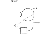
このようにして電極部材1を装着した後には、電極2を介して画像パターンに対応する電気信号を網膜双極細胞Cに送信することにより、使用者の脳内に画像イメージを送り込むことができる。図6に示すように、眼球Pにおいて網膜上に装着される電極部材1には、電極2から延設される電線Wを介して信号回路7(本発明の信号送信部に該当する。)が接続されており、使用者(失明患者)に対しては、この信号回路7と電極部材1とを備えた人工網膜装置8が取り付けられる。信号回路7からは、複数の電極2に対して、画像イメージに対応する所定の電気信号が発信されるようになっており、その電気信号が電極2の先端部分2Aから網膜双極細胞Cに伝えられる。
ここで、信号回路7が複数の電極2に流す電気信号の処理方法(網膜刺激方法)について、図7および図8を参照しつつ説明する。図7では、縦横に6x6のマトリックス状に配置された三十六個の電極2が設けられた電極部材1を示している。例えば、全体として十文字の画像パターンを送信しようとする場合には、図中の「+」が付された電極(すなわち、十文字の画像パターンに対応する電極)に第1の刺激電圧(図8(A))を印加する。また、このとき、十文字の画像パターンの背景領域に対応する電極(図中の「−」が付された電極)には、接地電極に対して第1の刺激電圧とは逆極性の第2の刺激電圧(図8(B))を印加する。こうして、「+」と「−」との両極性を備えた刺激電圧が印加されるため、画像イメージのコントラストを向上させることができる。
このように本実施形態によれば、電極部材1が網膜上に装着されたときには、網膜Fに対しては支持部3の対向面3Aの面積よりも小さな面積を備えた位置決め突部5が接触するので、従来のように支持部102の裏面全体が網膜Fに接触する場合に比べると、網膜Fに対する圧迫の影響を減少できる。
また、位置決め突部5と固定用ピン4とを一つの構成により兼用させているので、別々に突設させた場合に比べると、電極部材1の構成をより簡易とすることができる。加えて、固定用ピン4は網膜Fと接触するので、応力がかかりやすい。このため、位置決め突部5と固定用ピン4とを兼用させることにより、最も応力がかかりやすい位置が固定されるので電極部材1全体の位置決めが行いやすい。
さらに、電気信号を与える電極2は、所定の高さを備えた針状に形成されているので、網膜双極細胞に対して直接に接触するようにして網膜上に装着される。このため、従来の電極101のように網膜神経節細胞を介して網膜双極細胞に電気信号を与える場合に比べると、実際に与えた画像イメージに近い画像を結像させることが可能となる。
また、電極2は、その先端部分2Aを除いて全周が絶縁体で被覆されていることから、電気信号が標的となる網膜双極細胞Cのみに与えられやすいので、実際に与えた画像イメージに近い画像を結像させることができる。
また、電極2を針状に形成して網膜内に突き刺すように構成しているので、接地電極6を網膜上に接触するように設けることができる。
さらに、網膜双極細胞にはON型とOFF型との二種類の細胞が存在するという特性を考慮し、複数の電極2に対して、画像パターンに対応する第1の刺激電圧と、その画像パターンの背景領域に接地電極6に対して逆極性の第2の刺激電圧とを印加するようにしたので、脳内に結像される画像パターンに十分なコントラストを与えることが可能となる。また、副次的な効果として、従来と同様のコントラストを備えた画像パターンを送信するときには(条件によっては、従来よりも良好なコントラストを備えた画像パターンを送信する場合でも)、全体として小さな電流で済むことになり、網膜Fに与える電気的なダメージを減少させることができる。
第2実施形態
次に、図9〜図11を参照しつつ、第2実施形態について説明する。まず図11を参照しつつ、本実施形態の構成について説明する。人工網膜装置10は、電極部材1と信号送信部11から構成されており、両部材1、11は電線Wにより接続されている。この人工網膜装置10は、眼球Gの内部に装着されるようになっている。信号送信部11は受信器であり、眼球Gの外部に設けられる送信機12からの結像用電気信号を無線方式で受信する。信号送信部11の外径は、約5mm〜約8mmであり、水晶体Hの内径よりとほぼ同等か、それよりも僅かに大きく形成されている。なお、送信機12には、画像信号を作成・制御するための信号制御装置13(例えば、CCDカメラ、マイクロコンピュータ等を備えている)が接続されている。
人工網膜装置10を眼球Gの内部に装着するには、図10に示すように、眼球前面において、水晶体Hの外周に沿うようにして切開することにより、開口Jを形成する。その開口Jから眼球Gの内部に、電極部材1及び信号送信部11を順に装着する。
本実施形態によれば、送信機12を介して、信号送信部11から伝えられた電気信号が電極2を介して網膜Fの網膜神経節細胞Dに伝達されて、脳内に画像イメージが結像される。
第3実施形態
次に、図12〜図16を参照しつつ、第3実施形態について説明する。まず、図14を参照しつつ、本実施形態の構成について説明する。人工網膜装置20は、電極部材1と、この電極部材1に電気信号を送る信号送信部21と、その電気信号を制御する制御装置(マイクロコンピュータを含む)22と、固定部23とを備えている。信号送信部21は受信器であり、眼球Gの外部に設けられる送信機24からの結像用電気信号を無線方式で受信する。制御装置22には、制御回路25と電源装置26とが設けられている。電源装置26は、例えばリチウム電池などの二次電池とされている。また、固定部23は、電極部材1を網膜上に固定するためのものである(構成については、後に詳述する。)固定部23は、コイルを兼ねる構成とされており、外部の一次コイル27から電磁誘導によって送電される電源を電源装置26に供給する。なお、送信機24には、画像信号を作成・制御するための信号制御装置29(例えば、CCDカメラ、マイクロコンピュータ等を備えている)が接続されている。また、信号制御装置29は、一次コイル27の制御も行う。
電極部材1と信号送信部21と制御装置22は、図15及び図16に示すように、略円筒状の筒状体28として一体に形成されている。筒状体28は、図14に示すように、ちょうど眼球Gの内部に収容可能な程度の大きさとされている。すなわち、筒状体28の長さは、眼球Gの黄班部から虹彩裏面までの長さとほぼ同等とされており、筒状体28の外径は、眼球Gの前部において、強膜と角膜との境界部分の径よりも僅かに小さくされている。
また、四個の固定部23は、筒状体28の前半部分(眼球G内において前半球部分に位置する部分。毛様体周辺部の内面。)の外周面の周方向に沿って、ほぼ均等に配置されており、それぞれ外方に張り出されている。各固定部23は、適度な弾性を備えた部材(例えば形状記憶合金)から構成されている。固定部23は、その両端縁が筒状体28の外表面に連結されており、ブリッジ状とされている。固定部23の前部23Aは、眼球G内壁の形状に合わせて、円弧状に形成されている。また、固定部23は、人工網膜装置20が眼球Gの内部に装着される前には、筒状体28の外表面に沿うようにして折り畳まれている。一方、人工網膜装置20が眼球Gの内部に装着された後には、図12及び図15に示すように、筒状体28の外径方向に張り出すと共に、眼球Gにおいて前半球部分の内壁に接触している。こうして、固定部23が筒状体28を眼球G内の後方に押圧することにより、電極部材1の支持部3を網膜F側に押圧することで、支持部3が網膜F上の所定の位置に固定される。
上記のように構成された人工網膜装置20を眼球Gの内部に装着するには、図13に示すように、眼球Gの前面を開放して開口Kを形成し、その開口Kから眼球Gの内部に人工網膜装置20を挿入する。なお、人工網膜装置20の眼球Gへの埋め込み手術の際には、固定部23が眼球G内壁に接触する位置よりも後方側を内周面に沿ってレーザ処理しておくことが好ましい。そのようなレーザ光凝固処理により、固定部23による網膜剥離が発生したとしても、黄班部方向への進行を規制できる。
本実施形態によれば、固定部23がコイルを兼ねる構成とされており、そのコイルに対して誘導電流を発生させることにより、制御装置22に対する電源を供給できる。
また、眼球Gの前面を開放して開口Kを形成する術式を用いることにより、人工網膜装置20の挿入を容易に行うことができる。
なお、本実施形態では、固定部23はコイルを兼ねる構成とされているが、この他の変形例として、アースを兼ねる構成としてもよい。また、本実施形態では、固定部23が支持部3の位置決めを行う構成とされているので、電極部材1の固定用ピン4は設ける必要はない。
【図面の簡単な説明】
第1図は、網膜の側断面図である。
第2図は、従来例における網膜刺激用電極部材を網膜に装着したときの側断面図である。
第3図は、従来例において、複数の電極に刺激電圧をかけたときの印加方法である。
第4図は、第1実施形態における網膜刺激用電極部材を網膜に装着したときの側断面図である。
第5図は、第1実施形態における網膜刺激用電極部材を網膜に装着したときの拡大側断面図である。
第6図は、第1実施形態における人工網膜装置の構成図である。
第7図は、第1実施形態において、複数の電極に刺激電圧をかけたときの印加方法である。
第8図は、第1実施形態において、複数の電極にかける第1の刺激電圧(A)と第2の刺激電圧(B)とを示すタイミングチャートである。
第9図は、第2実施形態における人工網膜装置を眼球内に装着したときの側断面図である。
第10図は、第2実施形態における人工網膜装置を眼球内に装着したときの切開の大きさを示す眼球の前面図である。
第11図は、第2実施形態における人工網膜装置の構成図である。
第12図は、第3実施形態における人工網膜装置を眼球内に装着したときの側断面図である。
第13図は、第3実施形態における人工網膜装置を眼球内に装着したときの切開の大きさを示す眼球の前面図である。
第14図は、第3実施形態における人工網膜装置の構成図である。
第15図は、第3実施形態における人工網膜装置を眼球内に装着した後の外形を示す図面である。(A)は正面図、(B)は側面図、(C)は背面図である。
第16図は、第3実施形態における人工網膜装置を眼球内に装着する前の側面図である。
なお、図中の符号は、それぞれ、1…網膜刺激用電極部材、2…電極、3…支持部、3A…対向面、4,23…固定部、5…位置決め突部、6…接地電極、7,11,21…信号送信部、22…制御装置、8,10,20…人工網膜装置、C…網膜双極細胞、F…網膜である。Technical field
The present invention relates to an electrode member for retinal stimulation, an artificial retinal apparatus using the electrode member, and the like.
Background art
Despite recent advances in medical technology, there is still no effective treatment for blindness. Blindness is not just a loss of visual function, but a disease that has a significant impact on the mental and social lives of patients. For this reason, there is an urgent need for a technique for treating blindness.
FIG. 1 shows a cross-sectional view of the retina. On the outside of the retina, there is a sclera A that forms the outer layer of the eyeball, and on the inside thereof there are photoreceptor cells B, retinal bipolar cells C, and retinal ganglion cells D in this order. Among them, the photoreceptor cell B plays a role of receiving light and converting it into an electrical signal, and the retinal bipolar cell C and the retinal ganglion cell D play a role of transmitting the electrical signal into the brain. The light that has entered from the front (downward in the figure) of the eyeball passes through the transparent retinal ganglion cell D and retinal bipolar cell C, is detected by the photoreceptor cell B, and is converted into an electrical signal. It is transmitted to the retinal ganglion cell D via the retinal bipolar cell C. The end of the retinal ganglion cell D has entered the brain, and the electrical signal forms an image in the brain.
FIG. 2 shows a cross-sectional view of a conventional retinal stimulation electrode member 100 (hereinafter referred to as electrode member 100) mounted on the retina. The
However, when the
In addition, although the portion where the
The present invention has been made in view of the above-described circumstances, and an object of the present invention is to form an image image actually transmitted without pressing the retina over a wide range more than necessary. The object is to provide an electrode member for retinal stimulation.
Another object is to provide an artificial retinal apparatus that can transmit an image signal into the brain using such an electrode member.
Disclosure of the invention
In order to solve the above problems, a first invention is an electrode member for retinal stimulation provided with a plurality of electrodes for transmitting an electrical signal to the retina and a support portion for holding these electrodes in a predetermined position. In addition, the opposing surface of the support portion that faces the retina is provided with a positioning protrusion that allows the electrode to contact the retina while restricting the entire facing surface from contacting the retina. It is characterized by that.
In this specification, the retina means a sensory neuroepithelial tissue located on the innermost side of the eyeball, and includes photoreceptor cells, retinal bipolar cells, and retinal ganglion cells.
In the present specification, the positioning protrusion is a protrusion protruding from the facing surface of the support portion toward the retina. Further, the position where the positioning protrusion is provided is not necessarily inside the support part, and may be provided at a position protruding from the side of the support part. Further, the number of positioning protrusions is not particularly limited and may be one or more. It is also possible to arrange a plurality of electrodes only in the central part of the support part and to use all the other peripheral parts of the support part as positioning protrusions.
According to the first invention, when the electrode member for stimulating the retina is mounted on the retina, the positioning protrusion of the support portion comes into contact with the retina. Compared with the case of contact, the influence of the pressure on the retina of the part to which the electrode intends to stimulate can be reduced.
2nd invention is a thing as described in 1st invention, Comprising: The said positioning protrusion serves as the fixing | fixed part which fixes the said support part on a retina, It is characterized by the above-mentioned.
In the first invention and the second invention, the shape of the electrode is not limited, and for example, it may be a planar electrode that contacts the retinal ganglion cell of the retina as in the prior art, or may be a needle-like electrode.
In the present specification, the fixing part means a part for fixing the support part of the electrode member for retinal stimulation at a predetermined position on the retina. (A) The support part is provided on the support part. And (b) those provided separately from the electrode member and fixed by pressing the support portion toward the retina. Among such configurations, those included in (a) are exemplified by pins reaching the sclera, adhesives, threads for sewing between the support member and the retina, etc., and included in (b) Is exemplified by a member that fixes the support portion by pressing the front hemisphere inside the eyeball.
For example, (1) means that the same physical configuration is used as the positioning projection so that the tip surface (contact surface to the retina) of the positioning projection is fixed on the retina using an adhesive or a thread. In addition to the case where the fixing portion is also used, (2) the base end portion of the pin as the fixing portion is formed thick with a step so that the step serves as a positioning protrusion that contacts the retina. In addition, the configuration in the case where a part of the fixed portion is also used as the positioning protrusion is included.
According to the second invention, since the positioning protrusion and the fixing part are combined with one structure, the structure of the electrode member for retinal stimulation can be simplified as compared with the case where the protrusion is provided separately. Can do.
A third invention is an electrode member for retinal stimulation provided with a plurality of electrodes for transmitting an electrical signal to the retina and a support portion for holding these electrodes in a predetermined position, wherein the electrode is the support It is characterized by projecting in a needle shape having a height reaching the retinal bipolar cell of the retina from the facing surface facing the retina in the part.
The protruding height of the electrode should be at least high enough to reach the retinal bipolar cell from the surface side of the retina (retinal ganglion cell side). Since the height is expected to be different for each blind patient, it is preferable to measure in advance for each actual patient. As described above, the protruding height of the electrode cannot be generally defined, but is generally about 100 μm to about 300 μm.
According to the third aspect of the invention, since the electrode for giving an electric signal is formed in a needle shape having a predetermined height, the electrode is mounted on the retina so as to be in direct contact with the retinal bipolar cell. The For this reason, it is possible to form an image close to the actually applied image compared to the case where an electrical signal is applied to the retinal bipolar cell via the retinal ganglion cell as in the prior art.
A fourth invention is the electrode member for retinal stimulation according to any one of the first invention and the second invention, wherein the electrode is a retinal bipolar cell of the retina from a facing surface facing the retina in the support portion. It is characterized by protruding in a needle shape with a reaching height.
According to the fourth invention, since the positioning projection is provided, the influence of the pressure on the retina can be reduced, and the needle-like electrode directly transmits an electrical signal to the retinal bipolar cell, so that the actual signal is applied. An image close to the image can be formed.
A fifth invention is characterized in that, in the third and fourth inventions, the electrode is covered with an insulator on the entire circumference except for the tip portion.
“Excluding the tip” indicates that the electrical signal provided by the electrode is configured to stimulate only the targeted retinal bipolar cells and avoid stimulating other cells.
According to the fifth aspect, since the electric signal is easily given only to the target retinal bipolar cell, an image close to the actually given image can be formed.
A sixth invention is characterized in that, in the third to fifth inventions, a ground electrode is provided on the opposing surface of the support portion.
The portion where the ground electrode is provided may be a part of the opposing surface of the support portion or may be provided on the entire opposing surface.
When the planar electrode is provided on the opposite surface of the support portion, the ground electrode cannot be brought into contact with the retina, and the ground electrode is provided at a site different from the eyeball. However, according to the sixth invention, since the electrode is formed in a needle shape and pierced into the retina, the ground electrode can be provided in contact with the retina.
The seventh invention applies a first stimulation voltage to electrodes corresponding to a predetermined image pattern with respect to a plurality of electrodes for retinal stimulation arranged in a matrix form vertically and horizontally, and a background of the image pattern. In the retinal stimulation method, a second stimulation voltage having a polarity opposite to that of the first stimulation voltage is applied to the ground electrode and the electrode corresponding to the region.
An eighth invention provides an electrode member for retinal stimulation according to any one of
The signal transmission unit functions to send an electrical signal to the electrode. The signal transmission unit can be provided outside the eyeball via an electric wire extending from the electrode, but the signal transmission unit is provided integrally with the electrode member for retinal stimulation and embedded in the eyeball. It is preferable to do. In that case, it is preferable that a circuit for transmitting a signal is provided outside the user's body and an electric signal is transmitted to the signal transmission unit by a wireless method (for example, radio wave, optical signal, etc.).
According to the eighth aspect, the electrical signal transmitted from the signal transmission unit is transmitted to the retinal ganglion cell of the retina via the electrode, and an image image is formed in the brain.
According to a ninth aspect of the present invention, there is provided an electrode member for retinal stimulation provided with a plurality of electrodes that transmit electrical signals to the retina and a support portion that holds the electrodes in a predetermined position, and the electrode member is fixed on the retina. In the artificial retinal apparatus including a fixing unit and a signal transmission unit that transmits an electrical signal for imaging to the electrodes, the plurality of electrodes are arranged in a matrix in the vertical and horizontal directions. A first stimulation voltage is applied to the electrode corresponding to the image pattern of the second, and a second polarity having a polarity opposite to that of the first stimulation voltage is applied to the electrode corresponding to the background area of the image pattern with respect to the ground electrode. The stimulating voltage is applied.
According to a tenth aspect of the present invention, there is provided an electrode member for retinal stimulation according to any one of
There are two types of retinal bipolar cells: an ON type that sends positive voltage pulses to retinal ganglion cells and an OFF type that sends negative voltage pulses to retinal ganglion cells in response to light stimulation to photoreceptor cells. Is known to exist. In the conventional artificial retina device, the stimulation voltage is applied only to the electrode corresponding to the image pattern among the plurality of electrodes, and thus it is difficult to obtain sufficient contrast for the image pattern.
Therefore, in the seventh invention, the ninth invention, and the tenth invention, in consideration of the ON-type and OFF-type retinal bipolar cells, the first stimulation voltage corresponding to the image pattern and the background of the image pattern Since the second stimulation voltage having a reverse polarity with respect to the ground electrode is applied to the region, it is possible to give sufficient contrast to the image pattern imaged in the brain.
An eleventh aspect of the invention is characterized in that, in the tenth aspect of the invention, a control device that controls the electrical signal for image formation is provided, and the fixing portion also serves as a coil that can supply power to the control device. .
When the signal transmission unit and the electrode member are mounted in the eyeball, it is preferable to wirelessly transmit a signal from the outside of the eyeball to the signal transmission unit. In the case of such a configuration, it is preferable to further provide a control device (for example, a microcomputer) for controlling an electric signal between the signal transmission unit and the electrode member. However, in that case, it becomes difficult to supply power to the control device. Therefore, in the present invention, the fixed portion also serves as a coil, and an induced current is generated for the coil, so that Added power supply.
A twelfth aspect of the invention is a surgical method characterized in that the front of the eyeball is opened to form an opening, and an artificial retinal device is inserted into the eyeball through the opening. Moreover, it is preferable that the artificial retina apparatus at this time is as described in any one of the eighth invention to the eleventh invention.
For a person who undergoes an operation for embedding the artificial retinal apparatus described in the eighth to eleventh inventions in the eyeball, it is not always necessary to leave the tissue (for example, the cornea) in front of the eyeball. For this reason, it becomes possible to open the front surface of the eyeball to form an opening, and in such a technique, the artificial retinal device can be easily inserted.
BEST MODE FOR CARRYING OUT THE INVENTION
Next, several embodiments for carrying out the present invention will be described in detail with reference to the drawings. However, the technical scope of the present invention is not limited by the following embodiments, and can be implemented with various modifications without changing the gist. Further, the technical scope of the present invention extends to an equivalent range.
First embodiment
The first embodiment will be described with reference to FIGS. FIG. 1 shows a cross-sectional view of the retina F in a healthy person. As described above, there is a sclera A that covers the outer surface of the eyeball on the outside of the retina F, and photoreceptor cells B, retinal bipolar cells C, and retinal ganglion cells D exist in that order. As a pathological condition of a patient with retinitis pigmentosa or age-related macular degeneration who is expected to be applied with the
Next, a description will be given with reference to FIGS. FIG. 4 shows a state when the
In addition, at the four corners of the
The positioning projection 5 is formed of a synthetic resin into a substantially cylindrical shape having an inner diameter slightly smaller than the outer diameter of the fixing
Further, as shown in FIG. 5, a
In order to mount the
After the
Here, the processing method (retinal stimulation method) of the electric signal that the signal circuit 7 flows to the plurality of
Thus, according to the present embodiment, when the
In addition, since the positioning protrusion 5 and the fixing
Furthermore, since the
Moreover, since the
Further, since the
Further, in consideration of the characteristic that there are two types of cells, ON type and OFF type, in the retinal bipolar cell, the first stimulation voltage corresponding to the image pattern and the image pattern are applied to the plurality of
Second embodiment
Next, a second embodiment will be described with reference to FIGS. First, the configuration of the present embodiment will be described with reference to FIG. The
In order to mount the
According to this embodiment, the electrical signal transmitted from the
Third embodiment
Next, a third embodiment will be described with reference to FIGS. First, the configuration of the present embodiment will be described with reference to FIG. The artificial
As shown in FIGS. 15 and 16, the
The four fixing
In order to mount the
According to the present embodiment, the fixing
In addition, by using a technique in which the front surface of the eyeball G is opened to form the opening K, the
In addition, in this embodiment, although the fixing | fixed
[Brief description of the drawings]
FIG. 1 is a sectional side view of the retina.
FIG. 2 is a side sectional view of the conventional example when the electrode member for stimulating retina is attached to the retina.
FIG. 3 shows an application method when a stimulation voltage is applied to a plurality of electrodes in the conventional example.
FIG. 4 is a side cross-sectional view when the electrode member for retinal stimulation in the first embodiment is attached to the retina.
FIG. 5 is an enlarged cross-sectional side view when the electrode member for retinal stimulation in the first embodiment is attached to the retina.
FIG. 6 is a configuration diagram of the artificial retina device in the first embodiment.
FIG. 7 shows an application method when a stimulation voltage is applied to a plurality of electrodes in the first embodiment.
FIG. 8 is a timing chart showing a first stimulation voltage (A) and a second stimulation voltage (B) applied to a plurality of electrodes in the first embodiment.
FIG. 9 is a side sectional view when the artificial retina device in the second embodiment is mounted in the eyeball.
FIG. 10 is a front view of the eyeball showing the size of the incision when the artificial retina apparatus in the second embodiment is mounted in the eyeball.
FIG. 11 is a configuration diagram of the artificial retina device in the second embodiment.
FIG. 12 is a side sectional view when the artificial retina device in the third embodiment is mounted in the eyeball.
FIG. 13 is a front view of the eyeball showing the size of the incision when the artificial retina apparatus in the third embodiment is mounted in the eyeball.
FIG. 14 is a configuration diagram of the artificial retina device in the third embodiment.
FIG. 15 is a drawing showing an outer shape after the artificial retina device in the third embodiment is mounted in the eyeball. (A) is a front view, (B) is a side view, and (C) is a rear view.
FIG. 16 is a side view before the artificial retinal apparatus according to the third embodiment is mounted in the eyeball.
The reference numerals in the figure are: 1 ... electrode member for retinal stimulation, 2 ... electrode, 3 ... support part, 3A ... opposing surface, 4, 23 ... fixing part, 5 ... positioning protrusion, 6 ... ground electrode, 7, 11, 21 ... signal transmission unit, 22 ... control device, 8, 10, 20 ... artificial retina device, C ... retinal bipolar cell, F ... retina.
Claims (4)
前記電極は、前記支持部において網膜に対向する対向面から、網膜の網膜双極細胞に到達する高さを備えた針状に突設されていると共に、前記対向面には、前記支持部を網膜上に固定する固定用ピンが設けられ、この固定用ピンの周囲には、前記電極の突設高さよりも高い位置まで突設された位置決め突部が設けられており、当該網膜刺激用電極部材が網膜上に装着されると、前記位置決め突部の下端面が強膜に当接することで位置決めがなされると共に、前記位置決め突部の高さと前記電極の突設高さとの差によって、前記電極の先端部分が、網膜神経節細胞を通り越えて網膜双極細胞に接触するようになっていることを特徴とする網膜刺激用電極部材。A retina stimulation electrode member provided with a plurality of electrodes that transmit electrical signals to the retina and a support that holds these electrodes in a predetermined position,
The electrode protrudes in a needle shape having a height reaching the retinal bipolar cell of the retina from the facing surface facing the retina in the support portion. A fixing pin is provided for fixing on the top, and a positioning protrusion is provided around the fixing pin so as to protrude to a position higher than the protruding height of the electrode. Is mounted on the retina, positioning is performed by the lower end surface of the positioning protrusion contacting the sclera, and the electrode is determined by the difference between the height of the positioning protrusion and the protruding height of the electrode. An electrode member for retinal stimulation, characterized in that the tip portion of the electrode passes through the retinal ganglion cell and comes into contact with the retinal bipolar cell .
Applications Claiming Priority (3)
| Application Number | Priority Date | Filing Date | Title |
|---|---|---|---|
| JP2001101483 | 2001-03-30 | ||
| JP2001101483 | 2001-03-30 | ||
| PCT/JP2002/001340 WO2002080816A1 (en) | 2001-03-30 | 2002-02-15 | Electrode member for retinal stimulation, and artificial retinal device using the electrode member |
Publications (2)
| Publication Number | Publication Date |
|---|---|
| JPWO2002080816A1 JPWO2002080816A1 (en) | 2004-07-29 |
| JP4130589B2 true JP4130589B2 (en) | 2008-08-06 |
Family
ID=18954785
Family Applications (1)
| Application Number | Title | Priority Date | Filing Date |
|---|---|---|---|
| JP2002578855A Expired - Fee Related JP4130589B2 (en) | 2001-03-30 | 2002-02-15 | Retina stimulation electrode member, and artificial retinal device using the electrode member |
Country Status (3)
| Country | Link |
|---|---|
| US (1) | US7158836B2 (en) |
| JP (1) | JP4130589B2 (en) |
| WO (1) | WO2002080816A1 (en) |
Cited By (3)
| Publication number | Priority date | Publication date | Assignee | Title |
|---|---|---|---|---|
| JP2009531094A (en) * | 2006-03-31 | 2009-09-03 | アイエムアイ インテリジェント メディカル インプランツ アクチエンゲゼルシャフト | Device for reversibly attaching an implant to the eye |
| JP2011167255A (en) * | 2010-02-16 | 2011-09-01 | Nidek Co Ltd | Vision regeneration assisting apparatus |
| KR20190066856A (en) | 2017-12-06 | 2019-06-14 | 재단법인대구경북과학기술원 | Balloon-type retinal stimulation device and method for manufacturing the same |
Families Citing this family (38)
| Publication number | Priority date | Publication date | Assignee | Title |
|---|---|---|---|---|
| US6976998B2 (en) | 2002-01-17 | 2005-12-20 | Massachusetts Institute Of Technology | Minimally invasive retinal prosthesis |
| JP4138407B2 (en) * | 2002-08-30 | 2008-08-27 | 株式会社ニデック | Intraocular implant device |
| JP4204066B2 (en) * | 2002-12-05 | 2009-01-07 | 保雄 田野 | Artificial vision system |
| US7321795B2 (en) * | 2003-03-24 | 2008-01-22 | Les Bogdanowicz | Compositions for electric stimulation of the eye |
| DE102005032989A1 (en) * | 2005-07-14 | 2007-01-25 | Imi Intelligent Medical Implants Ag | Extraocular epiretinal implant |
| US8457752B2 (en) * | 2005-09-16 | 2013-06-04 | Second Sight Medical Products, Inc. | Neural stimulation for increased contrast |
| US20070093877A1 (en) * | 2005-10-26 | 2007-04-26 | Beecham Michael C | System for maintaining normal health of retinal cells and promoting regeneration of retinal cells |
| DE102005056771A1 (en) * | 2005-11-28 | 2007-08-02 | Gerding, Heinrich, Prof. Dr. | Retina implant for electrical stimulation of the retina |
| US8190266B2 (en) | 2006-02-15 | 2012-05-29 | Dohey Eye Institute | Wide-field retinal prosthesis |
| US20070191910A1 (en) * | 2006-02-16 | 2007-08-16 | Qiushi Ren | Visual prosthesis |
| DE102006048819A1 (en) * | 2006-10-10 | 2008-04-17 | NMI Naturwissenschaftliches und Medizinisches Institut an der Universität Tübingen | Device with a basic body |
| US7905013B2 (en) * | 2007-06-04 | 2011-03-15 | Sharp Laboratories Of America, Inc. | Method for forming an iridium oxide (IrOx) nanowire neural sensor array |
| JP4472727B2 (en) * | 2007-06-14 | 2010-06-02 | オリンパスメディカルシステムズ株式会社 | Endoscope device |
| US8489206B2 (en) * | 2007-07-16 | 2013-07-16 | Francisco José Arriaza Muñoz | Device for neuronal therapies |
| US8150526B2 (en) | 2009-02-09 | 2012-04-03 | Nano-Retina, Inc. | Retinal prosthesis |
| US8718784B2 (en) * | 2010-01-14 | 2014-05-06 | Nano-Retina, Inc. | Penetrating electrodes for retinal stimulation |
| US8442641B2 (en) | 2010-08-06 | 2013-05-14 | Nano-Retina, Inc. | Retinal prosthesis techniques |
| US8428740B2 (en) | 2010-08-06 | 2013-04-23 | Nano-Retina, Inc. | Retinal prosthesis techniques |
| US8706243B2 (en) | 2009-02-09 | 2014-04-22 | Rainbow Medical Ltd. | Retinal prosthesis techniques |
| US8530265B2 (en) | 2010-10-27 | 2013-09-10 | National Tsing Hua University | Method of fabricating flexible artificial retina devices |
| US8954156B2 (en) | 2010-10-27 | 2015-02-10 | National Tsing Hua University | Methods and apparatuses for configuring artificial retina devices |
| US9114004B2 (en) | 2010-10-27 | 2015-08-25 | Iridium Medical Technology Co, Ltd. | Flexible artificial retina devices |
| US8571669B2 (en) | 2011-02-24 | 2013-10-29 | Nano-Retina, Inc. | Retinal prosthesis with efficient processing circuits |
| US8613135B2 (en) | 2011-05-06 | 2013-12-24 | National Tsing Hua University | Method for non-planar chip assembly |
| US9155881B2 (en) | 2011-05-06 | 2015-10-13 | Iridium Medical Technology Co, Ltd. | Non-planar chip assembly |
| US9370417B2 (en) | 2013-03-14 | 2016-06-21 | Nano-Retina, Inc. | Foveated retinal prosthesis |
| US9474902B2 (en) | 2013-12-31 | 2016-10-25 | Nano Retina Ltd. | Wearable apparatus for delivery of power to a retinal prosthesis |
| US9331791B2 (en) | 2014-01-21 | 2016-05-03 | Nano Retina Ltd. | Transfer of power and data |
| US10226625B2 (en) | 2016-11-03 | 2019-03-12 | Nano Retina Ltd. | Surgical techniques for implantation of a retinal implant |
| US10272244B2 (en) | 2016-11-03 | 2019-04-30 | Nano Retina Ltd. | Retinal implant fixation |
| US10583283B2 (en) | 2018-01-31 | 2020-03-10 | Nano-Retina, Inc. | Retinal implant with image registration |
| AU2019352954B2 (en) | 2018-10-01 | 2022-03-10 | I-Lumen Scientific, Inc. | System and methods for controlled electrical modulation for vision therapy |
| WO2020112980A2 (en) | 2018-11-30 | 2020-06-04 | Biovisics Medical, Llc | Head worn apparatuses for vision therapy |
| WO2020210471A1 (en) | 2019-04-10 | 2020-10-15 | Biovisics Medical, Inc. | Systems and interfaces for ocular therapy |
| EP3983055B1 (en) | 2019-06-14 | 2024-09-11 | Biovisics Medical, Inc. | Wearable medical device |
| WO2021011255A1 (en) | 2019-07-12 | 2021-01-21 | Biovisics Medical, Inc. | Ocular therapy modes and systems |
| JP7535122B2 (en) | 2020-03-23 | 2024-08-15 | テクタス コーポレイション | Electronic intraocular devices |
| CN118105627A (en) * | 2024-03-26 | 2024-05-31 | 杭州暖芯迦电子科技有限公司 | Magnetic artificial retina and its manufacturing method |
Family Cites Families (9)
| Publication number | Priority date | Publication date | Assignee | Title |
|---|---|---|---|---|
| US4628933A (en) * | 1985-07-23 | 1986-12-16 | Michelson Robin P | Method and apparatus for visual prosthesis |
| US5024223A (en) | 1989-08-08 | 1991-06-18 | Chow Alan Y | Artificial retina device |
| US5016633A (en) | 1989-08-08 | 1991-05-21 | Chow Alan Y | Artificial retina device |
| US5556423A (en) | 1993-05-03 | 1996-09-17 | Alan Y. Chow | Independent photoelectric artificial retina device and method of using same |
| US5397350A (en) | 1993-05-03 | 1995-03-14 | Chow; Alan Y. | Independent photoelectric artificial retina device and method of using same |
| US5836996A (en) * | 1996-12-30 | 1998-11-17 | Doorish; John F. | Artificial retina |
| US5865839A (en) * | 1996-12-30 | 1999-02-02 | Doorish; John F. | Artificial retina |
| US5935155A (en) * | 1998-03-13 | 1999-08-10 | John Hopkins University, School Of Medicine | Visual prosthesis and method of using same |
| US8180453B2 (en) * | 1999-03-24 | 2012-05-15 | Second Sight Medical Products, Inc. | Electrode array for neural stimulation |
-
2002
- 2002-02-15 JP JP2002578855A patent/JP4130589B2/en not_active Expired - Fee Related
- 2002-02-15 US US10/469,559 patent/US7158836B2/en not_active Expired - Fee Related
- 2002-02-15 WO PCT/JP2002/001340 patent/WO2002080816A1/en not_active Ceased
Cited By (6)
| Publication number | Priority date | Publication date | Assignee | Title |
|---|---|---|---|---|
| JP2009531094A (en) * | 2006-03-31 | 2009-09-03 | アイエムアイ インテリジェント メディカル インプランツ アクチエンゲゼルシャフト | Device for reversibly attaching an implant to the eye |
| JP4886025B2 (en) * | 2006-03-31 | 2012-02-29 | アイエムアイ インテリジェント メディカル インプランツ アクチエンゲゼルシャフト | Device for reversibly attaching an implant to the eye |
| US9636212B2 (en) | 2006-03-31 | 2017-05-02 | Pixium Vision Sa | Device for reversibly attaching an implant in an eye |
| JP2011167255A (en) * | 2010-02-16 | 2011-09-01 | Nidek Co Ltd | Vision regeneration assisting apparatus |
| KR20190066856A (en) | 2017-12-06 | 2019-06-14 | 재단법인대구경북과학기술원 | Balloon-type retinal stimulation device and method for manufacturing the same |
| US11771896B2 (en) | 2017-12-06 | 2023-10-03 | Daegu Gyeongbuk Institute Of Science And Technology | Balloon-type retinal stimulation device and method for manufacturing same |
Also Published As
| Publication number | Publication date |
|---|---|
| US7158836B2 (en) | 2007-01-02 |
| US20040078064A1 (en) | 2004-04-22 |
| WO2002080816A1 (en) | 2002-10-17 |
| JPWO2002080816A1 (en) | 2004-07-29 |
Similar Documents
| Publication | Publication Date | Title |
|---|---|---|
| JP4130589B2 (en) | Retina stimulation electrode member, and artificial retinal device using the electrode member | |
| JP6746767B2 (en) | Implantable Micro Stimulation Unit | |
| US10328262B2 (en) | Stimulation devices and methods | |
| JP4138407B2 (en) | Intraocular implant device | |
| CN103313754B (en) | Systems and methods for treating dry eye | |
| JP3599237B2 (en) | Retina implant and method for manufacturing the same | |
| US7974699B2 (en) | Vision regeneration assisting device | |
| US7398124B2 (en) | Visual restoration aiding device | |
| JP2002505910A (en) | Artificial eye | |
| JP2003531697A (en) | Artificial retinal device in which stimulation electrode and ground return electrode are arranged on both sides of neural retina and method for wearing the same | |
| JP2008529684A (en) | Neural stimulation with increased persistence | |
| JP2008539891A (en) | Artificial retina with separate central and peripheral electrode arrays | |
| CN111481344B (en) | Implant device and visual prosthesis having the same | |
| JP2003230590A (en) | Intraocular implanting device | |
| JP2005279001A (en) | Visual reproduction assisting apparatus | |
| JP2005080360A (en) | Visual recovery auxiliary apparatus | |
| JP2003230581A (en) | Intraocular implanting device | |
| JP4188034B2 (en) | Intraocular implant device | |
| WO2021238419A1 (en) | Implantation device and visual prosthesis having same |
Legal Events
| Date | Code | Title | Description |
|---|---|---|---|
| A621 | Written request for application examination |
Free format text: JAPANESE INTERMEDIATE CODE: A621 Effective date: 20050112 |
|
| A131 | Notification of reasons for refusal |
Free format text: JAPANESE INTERMEDIATE CODE: A131 Effective date: 20080115 |
|
| A521 | Request for written amendment filed |
Free format text: JAPANESE INTERMEDIATE CODE: A523 Effective date: 20080303 |
|
| TRDD | Decision of grant or rejection written | ||
| A01 | Written decision to grant a patent or to grant a registration (utility model) |
Free format text: JAPANESE INTERMEDIATE CODE: A01 Effective date: 20080520 |
|
| A01 | Written decision to grant a patent or to grant a registration (utility model) |
Free format text: JAPANESE INTERMEDIATE CODE: A01 |
|
| A61 | First payment of annual fees (during grant procedure) |
Free format text: JAPANESE INTERMEDIATE CODE: A61 Effective date: 20080522 |
|
| R150 | Certificate of patent or registration of utility model |
Free format text: JAPANESE INTERMEDIATE CODE: R150 |
|
| FPAY | Renewal fee payment (event date is renewal date of database) |
Free format text: PAYMENT UNTIL: 20110530 Year of fee payment: 3 |
|
| FPAY | Renewal fee payment (event date is renewal date of database) |
Free format text: PAYMENT UNTIL: 20120530 Year of fee payment: 4 |
|
| FPAY | Renewal fee payment (event date is renewal date of database) |
Free format text: PAYMENT UNTIL: 20130530 Year of fee payment: 5 |
|
| FPAY | Renewal fee payment (event date is renewal date of database) |
Free format text: PAYMENT UNTIL: 20140530 Year of fee payment: 6 |
|
| R250 | Receipt of annual fees |
Free format text: JAPANESE INTERMEDIATE CODE: R250 |
|
| LAPS | Cancellation because of no payment of annual fees |