JP4121601B2 - Apparatus for molding cast spectacle lenses with mold assemblies - Google Patents
Apparatus for molding cast spectacle lenses with mold assemblies Download PDFInfo
- Publication number
- JP4121601B2 JP4121601B2 JP03798798A JP3798798A JP4121601B2 JP 4121601 B2 JP4121601 B2 JP 4121601B2 JP 03798798 A JP03798798 A JP 03798798A JP 3798798 A JP3798798 A JP 3798798A JP 4121601 B2 JP4121601 B2 JP 4121601B2
- Authority
- JP
- Japan
- Prior art keywords
- mold
- base curve
- basecurve
- lens
- curve mold
- Prior art date
- Legal status (The legal status is an assumption and is not a legal conclusion. Google has not performed a legal analysis and makes no representation as to the accuracy of the status listed.)
- Expired - Lifetime
Links
Images


Classifications
-
- B—PERFORMING OPERATIONS; TRANSPORTING
- B29—WORKING OF PLASTICS; WORKING OF SUBSTANCES IN A PLASTIC STATE IN GENERAL
- B29C—SHAPING OR JOINING OF PLASTICS; SHAPING OF MATERIAL IN A PLASTIC STATE, NOT OTHERWISE PROVIDED FOR; AFTER-TREATMENT OF THE SHAPED PRODUCTS, e.g. REPAIRING
- B29C33/00—Moulds or cores; Details thereof or accessories therefor
- B29C33/44—Moulds or cores; Details thereof or accessories therefor with means for, or specially constructed to facilitate, the removal of articles, e.g. of undercut articles
-
- B—PERFORMING OPERATIONS; TRANSPORTING
- B29—WORKING OF PLASTICS; WORKING OF SUBSTANCES IN A PLASTIC STATE IN GENERAL
- B29C—SHAPING OR JOINING OF PLASTICS; SHAPING OF MATERIAL IN A PLASTIC STATE, NOT OTHERWISE PROVIDED FOR; AFTER-TREATMENT OF THE SHAPED PRODUCTS, e.g. REPAIRING
- B29C33/00—Moulds or cores; Details thereof or accessories therefor
- B29C33/0055—Moulds or cores; Details thereof or accessories therefor with incorporated overflow cavities
-
- B—PERFORMING OPERATIONS; TRANSPORTING
- B29—WORKING OF PLASTICS; WORKING OF SUBSTANCES IN A PLASTIC STATE IN GENERAL
- B29C—SHAPING OR JOINING OF PLASTICS; SHAPING OF MATERIAL IN A PLASTIC STATE, NOT OTHERWISE PROVIDED FOR; AFTER-TREATMENT OF THE SHAPED PRODUCTS, e.g. REPAIRING
- B29C37/00—Component parts, details, accessories or auxiliary operations, not covered by group B29C33/00 or B29C35/00
- B29C37/0003—Discharging moulded articles from the mould
-
- B—PERFORMING OPERATIONS; TRANSPORTING
- B29—WORKING OF PLASTICS; WORKING OF SUBSTANCES IN A PLASTIC STATE IN GENERAL
- B29D—PRODUCING PARTICULAR ARTICLES FROM PLASTICS OR FROM SUBSTANCES IN A PLASTIC STATE
- B29D11/00—Producing optical elements, e.g. lenses or prisms
- B29D11/00009—Production of simple or compound lenses
- B29D11/00038—Production of contact lenses
- B29D11/00057—Production of contact lenses characterised by the shape or surface condition of the edge, e.g. flashless, burrless, smooth
-
- Y—GENERAL TAGGING OF NEW TECHNOLOGICAL DEVELOPMENTS; GENERAL TAGGING OF CROSS-SECTIONAL TECHNOLOGIES SPANNING OVER SEVERAL SECTIONS OF THE IPC; TECHNICAL SUBJECTS COVERED BY FORMER USPC CROSS-REFERENCE ART COLLECTIONS [XRACs] AND DIGESTS
- Y10—TECHNICAL SUBJECTS COVERED BY FORMER USPC
- Y10S—TECHNICAL SUBJECTS COVERED BY FORMER USPC CROSS-REFERENCE ART COLLECTIONS [XRACs] AND DIGESTS
- Y10S425/00—Plastic article or earthenware shaping or treating: apparatus
- Y10S425/808—Lens mold
Landscapes
- Engineering & Computer Science (AREA)
- Mechanical Engineering (AREA)
- Health & Medical Sciences (AREA)
- Manufacturing & Machinery (AREA)
- Ophthalmology & Optometry (AREA)
- Moulds For Moulding Plastics Or The Like (AREA)
- Golf Clubs (AREA)
- Forging (AREA)
Abstract
Description
【0001】
【発明の属する技術分野】
本発明は、成形品の型抜き作業時に、HEMA(2−ヒドロキシエチルメタクリレート)からなる余分ポリマーHEMAのリング(excess polymer HEMA ring)が前面カーブと共に除去されるように、その余分ポリマーHEMAリングが型抜き作業時に前面カーブによく付着するように設計した前面カーブのデザイン(設計)を提供する。
【0002】
本発明は、各々が前面カーブと離れたベースカーブを備え、これらカーブの間に成形レンズを形成する鋳型アセンブリ(mold assembly)内でキャストコンタクトレンズを成形する方法において、前面カーブに余分ポリマーHEMAリングが付着されたままにする前面カーブ鋳型のデザイン(設計)に一般的に関する。本発明はキャストコンタクトレンズ鋳型アセンブリで眼鏡コンタクトレンズを製造する装置一般に関し、成形品型抜き作業時にベースカーブ鋳型と共に余分ポリマーHEMAリングを除去する改良した除去方法を提供する。
【0003】
本発明は、眼内レンズのような他の小さな、高精度の眼鏡レンズに対しても適するが、ヒドロゲルコンタクトレンズなどの成形した眼鏡レンズに対して特によく適するものである。
【0004】
【従来の技術】
眼鏡レンズ工業、特に、頻繁に周期的に取り替えるコンタクトレンズの供給に関するレンズ工業が発展するにつれ、製造が必要なコンタクトレンズの数も劇的に増大している。これは自動化とそれに伴う実施に適用できる自動化方法と装置を改良するようにメーカーは拍車をかけた。
【0005】
ポリスチレンあるいはポリプロピレンから作られた鋳型(モールド)などの鋳型でモノマーあるいはモノマー混合物を成形することにより、ソフトヒドロゲルコンタクトレンズなどの眼鏡レンズを製造することは、先行技術で一般に知られている。
【0006】
この先行技術の実施例は、米国特許第5,039,459号、第4,889,664号および第4,565,348号に見ることができる。これらの特許はポリスチレン鋳型の要件をその中で検討しており、鋳型部分が余分な力を必要とせずにレンズにあるいは互いに粘着して分離するように、材料、化学的性質および方法(プロセス)が制御される。上記ポリスチレン鋳型に対し、米国特許第4,121,896号に開示されているように、別の実施例としてポリプロピレン鋳型あるいはポリエチレン鋳型が使用されている。
【0007】
眼のコンタクトレンズを成形するための鋳型アセンブリは、前面カーブと称する下凹鋳型部分と、後面カーブと称する上凸鋳型部分を通常備えている。下前面カーブの凹面と上後面カーブの凸面は、コンタクトレンズの鋳型キャビティ(mold cavity)をその間に形成する。
【0008】
先行技術での特定の問題は、前面カーブと後面カーブが通常、フランジで包囲され、モノマーあるいはモノマー混合物が鋳型の組み立て前に凹前面カーブ鋳型に余分に供給されることである。レンズを規定しエッジを形成するように上記鋳型を共に配置すると、余分なモノマーあるいはモノマー混合物は、鋳型キャビティから排出され、1方の鋳型部分あるいは双方の鋳型部分のフランジにあるいはその間に滞留する。重合と同時に、この余分な材料は、鋳型アセンブリの周囲に環状リングを形成して、成形品型抜き時の鋳型部分の分離を妨げる。
【0009】
そのようなコンタクトレンズ製造プロセスにおける問題点、即ち、レンズの紛失や傷、亀裂などのレンズの欠陥は困難な型抜き作業から一部生じるものと考えられる。
成形品型抜き作業では、前面カーブを取り出しキャストコンタクトレンズだけを前面カーブに残す際に、余分ポリマーHEMAリングをベースカーブと共に除去するため、余分ポリマーHEMAリングがベースカーブに付着したままであることが望ましい。
【0010】
【発明が解決しようとする課題】
従って、本発明の第1の目的は、成形品の型抜き作業時に余分ポリマーHEMAリングが前面カーブと共に除去されるように、その余分ポリマーHEMAリングが型抜き作業時に前面カーブによく付着するように設計した前面カーブのデザインを提供することである。
【0011】
本発明の他の目的は、ベースカーブ鋳型が前面カーブ鋳型に付着した余分ポリマーHEMAリングと共にその間に形成されたコンタクトレンズを損傷させないで、前面カーブ鋳型から容易に繰返して分離でき、それにより欠陥の無いコンタクトレンズの製造を向上させレンズ亀裂やレンズ鋳型部品の破損を最小にする鋳型アセンブリで、キャストコンタクトレンズを製造する改良された装置を提供することである。
【0012】
本発明はベースカーブ面を機械的な仕上がりあるいは特徴にすることを基本的に開示し教示するものであり、そのことは余分ポリマーHEMAリングをベースカーブに付着するのを助ける。機械的な仕上がりあるいは特徴は、余分ポリマーHEMAリングが通常形成される領域のベースカーブに付与される。
【0013】
【課題を解決するための手段】
本明細書での教示によれば、本発明は、周囲フランジと共に中央レンズ鋳型部分を有する前面カーブ鋳型と、周囲フランジを備えた中央レンズ鋳型部分を有する対応するベースカーブを含み、成形された眼鏡レンズが前記前面カーブ鋳型と前記ベースカーブ鋳型の間で形成されるような鋳型アセンブリでキャスト眼鏡レンズを成形するための装置を提供する。
【0014】
成形プロセス時に、余分ポリマーHEMAリングは前記中央レンズ鋳型部分周囲に形成され、前記ベースカーブ鋳型はある表面外形(surface contour)を有して形成された、前記余分ポリマーHEMAリングに隣接する環状領域を含み、これが前記余分ポリマーHEMAリングと接触する前記ベースカーブ鋳型の表面積を増やし、そのHEMAリングのメニスカス効果(meniscus effect)を幾何学的に高めてベースカーブの表面を上げる。これによりレンズ鋳型アセンブリの型抜き時に前記余分ポリマーHEMAリングがベースカーブ鋳型で除去されるように、余分ポリマーHEMAリングのベースカーブ鋳型との付着を高める。
【0015】
さらに詳細に説明する。1つの実施形態ではベースカーブ鋳型の環状領域は、ベースカーブ鋳型をキャストするために使用される主鋳型(マスター鋳型)の対応する環状領域をレーザー加工することによって作られたレーザー加工傷で鋳型に形成される。第2の実施形態ではベースカーブ鋳型の環状領域は、ベースカーブ鋳型をキャストするために使用される主鋳型の対応する環状領域を放電加工することによって作られた放電加工傷で鋳型に形成される。他の実施形態ではベースカーブ鋳型の環状領域は、余分ポリマーHEMAリング内に突出した突出歯で形成される。また別の実施形態ではベースカーブ鋳型の環状領域は、余分ポリマーHEMAリングに接触する環状段差で形成される。さらに、その環状段差は余分ポリマーHEMAリングに突出した複数の突出歯をその周囲に有することができる。また別の実施形態ではベースカーブ鋳型の環状領域は、スポーク付きデザインあるいはエッジをカットしたデザインとすることができる。
【0016】
HEMAリング/ベースカーブの付着を維持するためのベースカーブ鋳型デザインの本発明の前述の目的と利点は、図に基づく幾つかの好ましい実施形態に関する以下の詳細な説明を参照すれば当業者は容易に理解できる。図では同様の要素は同一の参照番号で示してある。
【0017】
【発明の実施の形態】
図面、特に、図1及び図2を先ず詳細に参照する。図1は支持パレット10の正面図であり、その支持パレット10は、図2にさらに詳細に示されているコンタクトレンズ鋳型アセンブリ12の1つのアレー、典型的にはツーバイフォー(2×4)アレーをその上面に支持する。
【0018】
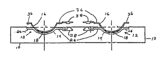
図2は1つのコンタクトレンズ鋳型アセンブリ12の拡大側面断面図であり、その鋳型アセンブリは、間でコンタクトレンズ18の鋳型キャビティを区画(形成)する下前面カーブ鋳型14と上ベースカーブ鋳型16からなる。
【0019】
下前面カーブ鋳型14と上ベースカーブ鋳型16はポリスチレンで形成するのが好ましいが、光を照射させてソフトコンタクトレンズの連続的な重合を促進するために、紫外線に対し充分に透過性がある、適切ないかなる熱可塑性ポリマーでもよいだろう。ポリスチレン等のふさわしい熱可塑性樹脂は、比較的低い温度で光学的特性を有する面に成形することができ、優れた流れ特性を有し、成形時に結晶化しないで非晶質ままであり、しかも冷却時には収縮が最小であるような望ましい特性をも備えている。
【0020】
下前面カーブ鋳型14は、光学的特性の凹面20を備えた中央のカーブした部分(湾曲部)を定める。光学的特性の凹面20には周囲に延在する丸い円周方向のナイフエッジ22が付いている。ナイフエッジ22は、連続的に成形したソフトコンタクトレンズ18のために鮮鋭で均一なプラスチックの丸い分割線(エッジ)を形成するのが通常好ましい。一般に平行な凸面24は凹面20から離れており、環状の本質的に一平面フランジ26は凹面20と凸面24から半径方向外側に延在して形成される。凹面20は、鋳型アセンブリによって製造されるコンタクトレンズの前面カーブ(屈折力カーブ)の寸法を有し、コンタクトレンズの表面に接触する重合可能な成形材料の重合により形成されるそのコンタクトレンズの表面が、光学的に許容できる特性を有するように十分滑らかである。前面カーブ鋳型は、通常0.8mmの薄さであり、熱を急速に全体に伝達させるのに効果的であると共に、型抜き時に前面カーブ鋳型を鋳型アセンブリから分離するのにかけられる梃子の力に耐えるのに効果的な剛性とを備えるように設計(デザイン)される。下前面カーブ鋳型14はさらに、フランジ26と一体で、フランジ26の片側から突出た一般に三角形のタブ28を定める。タブ28は本質的に一平面上にあり、溶融熱可塑性樹脂を供給する射出熱先端(ホットチップ)まで延在して前面カーブ鋳型を形成する。
【0021】
上ベースカーブ鋳型16は、光学的特性の凸面32と凸面32から離れた一般に平行な凹面34とを備えた中央のカーブ領域(湾曲部)および凸面32と凹面34から半径方向に外側に延在して形成された環状の本質的に一平面のフランジ36を定める。凸面32は、ベースカーブ鋳型によって製造されるコンタクトレンズの後面カーブ(目の角膜に載る)の寸法を有し、コンタクトレンズの表面に接触する重合可能な成形材料の重合により形成されるそのコンタクトレンズの表面が光学的に許容できる特性を有するように十分滑らかである。ベースカーブ鋳型は通常0.6mmの薄さと、熱を急速に全体に伝達させるのに効果的であると共に、型抜き時にベースカーブ鋳型を鋳型アセンブリから分離するのにかけられる梃子の力に耐えるのに効果的な剛性を備えて設計(デザイン)される。ベースカーブ鋳型16はさらに、フランジ36と一体でフランジ36の片側から突出する三角形のタブ28と同様の一般に三角形のタブ38を定める。タブ38は、溶融熱可塑性樹脂を供給する射出熱先端まで延在してベースカーブ鋳型を形成する。
【0022】
先行技術プロセスでコンタクトレンズを成形するプロセス時に、余分な量のポリマーあるいはポリマー混合物を、初めは前面カーブ鋳型に配置し、次に、ベースカーブ鋳型を前面カーブ鋳型の上に置き、それに押し付ける。これにより鋳型キャビティ内の余分なポリマーが移動し、鋳型キャビティから排除され、ナイフエッジ22の外部に余分ポリマーリング42を作る。
【0023】
フランジ26,36は、型抜きと鋳型の取扱いを補助し、また光学的表面とナイフエッジ22を保護するようにも設計されている。三角形のタブ28,38の形態は、型抜き前に組み立てられた前面カーブ/ベースカーブのアセンブリ12を真っ直ぐにし、一定方向に向ける補助機能の役割を果たす。下前面カーブ鋳型あるいはカーブ14を上ベースカーブ鋳型あるいはカーブ16と組立てると、ギャップ40が2つの離れたフランジと突き出たタブとの間に形成されるが、このことは型抜きに重要である。タブ間のギャップは1.0mm〜3.0mmの範囲にあるのが好ましく、型抜き作業を補助するために必要である。
【0024】
図1及び図2を参照すると、コンタクトレンズ鋳型アセンブリ12は、パレット10の上面の下にわずかに窪んだ下前面カーブ鋳型14の環状フランジ26とタブ28でパレット10内に支持されている。上ベースカーブ鋳型16の環状フランジ36とタブ38は、パレット10の上面上方に上げられており、機械的な分離部材を下前面カーブ鋳型14と上ベースカーブ鋳型16のそれぞれ離れたフランジ26,36との間に挿入することができる。
【0025】
図3は、成形品型抜き時に余分ポリマーHEMAリングを形成してその余分ポリマーリングのベースカーブに対する付着を高める周囲環状領域50に粗面をベースカーブ鋳型が有する鋳型アセンブリの概略図を示す。ベースカーブ鋳型の粗い環状領域50は、ベースカーブ鋳型をキャストするのに使用される主鋳型の粗い環状領域をレーザー加工することによって形成される。その粗い環状領域は、その周囲を走査するレーザービームによってリング状の融蝕用金属で形成された1つあるいは2つ以上のレーザー加工リングで主鋳型に形成することができる。
【0026】
図4は、ベースカーブ鋳型をキャストするのに使用される主鋳型を環状領域52に放電加工(EDM)して成形品の型抜き作業時に余分なポリマーHEMAリングのベースカーブのEDM面に対する付着を高める鋳型アセンブリの概略図である。
【0027】
図5は、ベースカーブ鋳型がその周囲の環状領域の表面にサメの歯54のデザインを有して成形品の型抜き作業時に余分ポリマーHEMAリングのベースカーブに対する付着を高める鋳型アセンブリの概略図である。
【0028】
図6は、ベースカーブ鋳型がその周囲に形成した環状段差60(三角形に近い断面を有する)を有して、余分ポリマーHEMAリングに接触するベースカーブ鋳型の環状面積62を増やし、成形品の型抜き作業時に余分ポリマーHEMAリングのベースカーブに対する付着を高める鋳型アセンブリの概略図である。
【0029】
図7は、環状段差70が突出歯72の環状リングを有して成形品の型抜き作業時に余分なポリマーHEMAリングのベースカーブに対する付着を高める図6に示した鋳型アセンブリと同様の環状段差70を有する鋳型アセンブリを示す。
【0030】
図8及び図9は、それぞれ図7のベースカーブの環状段差70の底面図と、図8の矢印9−9に沿って切断した拡大断面図である。図9では、歯72を囲む断面領域90が、突出歯周囲に形成された余分ポリマーHEMAリングとして想定できる。
【0031】
図10は、突出歯100の環状リングが環状段差102の外側半径方向エッジへ半径方向外側に置き換えられて成形品の型抜き作業時に余分ポリマーHEMAリングのベースカーブに対する付着を高める図7−9に示した鋳型アセンブリと同様の鋳型アセンブリを示す。
【0032】
図11及び図12は、それぞれ図10のベースカーブの底面図と図11の矢印12−12に沿って切断した拡大断面図である。同様に図12では、歯100を囲む断面領域120が、突出歯周囲に形成された余分ポリマーHEMAリングとして想定できる。
【0033】
図13乃至図17は、成形品の型抜き作業時に余分なポリマーHEMAリングのベースカーブに対する付着を高めるように設計されたベースカーブ表面の種々の実施形態のそれぞれ断面図である。図13乃至図17の実施形態では、その断面積は余分ポリマ−HEMAリングとして想定することができる。これらの実施形態の各々は、それぞれスポークデザイン130、歯デザイン140、エッジカットデザイン150、レーザー加工デザイン160、およびEDMデザイン170が形成される図6の環状段差と同様の環状段差を有する。
【0034】
HEMAリング/ベースカーブの付着を維持するためのベースカーブ鋳型デザインの本発明による幾つかの実施態様と変形を本明細書に詳細に説明したが、本発明の開示と教示によって当業者に対し別のデザインの多くが示唆されることが明らかになるはずである。
【0035】
発明の具体的な実施態様は以下の通りである。
(I)周囲フランジと共に中央レンズ鋳型部分を有する前面カーブ鋳型と、周囲フランジと共に中央レンズ鋳型部分を有する対応するベースカーブを含み、成形された眼鏡レンズが前記前面カーブ鋳型と前記ベースカーブ鋳型の間で形成される鋳型アセンブリでキャスト眼鏡レンズを成形するための装置であって、
成形プロセス時に余分ポリマーHEMAリングが前記中央レンズ鋳型部分の周囲に形成され、前記ベースカーブ鋳型は、表面外形を有して形成された、前記余分なポリマーHEMAリングに隣接する環状領域を含み、前記余分ポリマーHEMAリングと接触する前記ベースカーブ鋳型の表面積を増やし、レンズ鋳型アセンブリの型抜き時に前記余分ポリマーHEMAリングが前記ベースカーブ鋳型で除去されるように、前記余分ポリマーHEMAリングの前記ベースカーブ鋳型に対する付着を高めることを特徴とするキャスト眼鏡レンズを成形するための装置。
(1)前記ベースカーブ鋳型の環状領域は、そのベースカーブ鋳型をキャストするのに使用された主鋳型の対応する環状領域をレーザー加工することによって形成されたその部分へのレーザー加工傷で形成される実施態様(I)に記載の鋳型アセンブリでキャスト眼鏡レンズを成形するための装置。
(2)前記ベースカーブ鋳型の環状領域は、そのベースカーブ鋳型をキャストするのに使用された主鋳型の対応する環状領域を放電加工することによって形成されたその部分への放電加工傷で形成される実施態様(I)に記載の鋳型アセンブリでキャスト眼鏡レンズを成形するための装置。
【0036】
(3)前記ベースカーブ鋳型の環状領域は、前記余分ポリマーHEMAリング内に突出する突出歯で形成される実施態様(I)に記載の鋳型アセンブリでキャスト眼鏡レンズを成形するための装置。
(4)前記ベースカーブ鋳型の環状領域は、前記余分ポリマーHEMAリングに接触する環状段差で形成される実施態様(I)に記載の鋳型アセンブリでキャスト眼鏡レンズを成形するための装置。
(5)前記環状段差は、前記余分ポリマーHEMAリング内に突出して環状段差周囲に形成された複数の突出歯を有する実施態様(4)に記載の鋳型アセンブリでキャスト眼鏡レンズを成形するための装置。
【0037】
(6)前記ベースカーブ鋳型の環状領域はスポーク付きデザインを形成する実施態様(I)に記載の鋳型アセンブリでキャスト眼鏡レンズを成形するための装置。
(7)前記ベースカーブ鋳型の環状領域は歯のデザインを形成する実施態様(I)に記載の鋳型アセンブリでキャスト眼鏡レンズを成形するための装置。
(8)前記ベースカーブ鋳型の環状領域はエッジカットのデザインを形成する実施態様(I)に記載の鋳型アセンブリでキャスト眼鏡レンズを成形するための装置。
(9)前記ベースカーブ鋳型の環状領域はレーザー加工のデザインを形成する実施態様(I)に記載の鋳型アセンブリでキャスト眼鏡レンズを成形するための装置。
(10)前記ベースカーブ鋳型の環状領域は放電加工のデザインを形成する実施態様(I)に記載の鋳型アセンブリでキャスト眼鏡レンズを成形するための装置。
【0038】
【発明の効果】
以上説明したように、本発明による鋳型アセンブリでキャスト眼鏡レンズを成形するための装置によれば、成形品の型抜き作業時に余分ポリマーHEMAリングのベースカーブに対する付着を高めることができる。これによりレンズの紛失や、傷、亀裂等のレンズの欠陥や、レンズ鋳型部品の破損を防止することができる。
【図面の簡単な説明】
【図1】各々が下前面カーブ鋳型と上ベースカーブ鋳型からなり、その間でコンタクトレンズの鋳型キャビティを定める2×4アレーのコンタクトレンズ鋳型アセンブリを保持する支持パレットの正面図である。
【図2】典型的な先行技術のコンタクトレンズ鋳型アセンブリの拡大側面断面図であり、下前面カーブ鋳型と上ベースカーブ鋳型の詳細な構造を示す図である。
【図3】ベースカーブ鋳型をレーザー加工して成形品型抜き作業時に余分ポリマーリングのベースカーブに対する付着を高める鋳型アセンブリの概略図である。
【図4】ベースカーブ鋳型を放電加工(EDM)して成形品の型抜き作業時に余分ポリマーHEMAリングのベースカーブのEDM面に対する付着を高める鋳型アセンブリの概略図である。
【図5】ベースカーブ鋳型がサメの歯デザイン表面を有して成形品の型抜き作業時に余分なポリマーHEMAリングのベースカーブに対する付着を高める鋳型アセンブリの概略図である。
【図6】ベースカーブ鋳型が環状段差を有して成形品の型抜き作業時に余分なポリマーHEMAリングのベースカーブに対する付着を高める鋳型アセンブリの概略図である。
【図7】環状段差が突出歯の環状リングを有して成形品の型抜き作業時に余分ポリマーHEMAリングのベースカーブに対する付着を高める図6に示した鋳型アセンブリと同様の環状段差を有する鋳型アセンブリを示す図である。
【図8】図7のベースカーブの環状段差70の底面図である。
【図9】図8の矢印9−9に沿って切断した拡大断面図である。
【図10】環状段差が、外側半径方向エッジへに沿った突出歯の環状リングを有して成形品の型抜き作業時に余分ポリマーHEMAリングのベースカーブに対する付着を高める図7乃至図9に示した鋳型アセンブリと同様の鋳型アセンブリを示す。
【図11】図10のベースカーブの底面図である。
【図12】図11の矢印12−12に沿って切断した拡大断面図である。
【図13】成形品の型抜き作業時に余分ポリマーHEMAリングのベースカーブに対する付着を高めるように設計されたベースカーブ表面の種々の実施形態の1つであるスポークデザインを示す断面図である。
【図14】歯のデザインを示す図13と同様の断面図である。
【図15】エッジカットのデザインを示す図13と同様の断面図である。
【図16】レーザーデザインを示す図13と同様の断面図である。
【図17】EDMデザインを示す図13と同様の断面図である。[0001]
BACKGROUND OF THE INVENTION
In the present invention, the excess polymer HEMA ring made of HEMA (2-hydroxyethyl methacrylate ) is removed together with the front curve so that the excess polymer HEMA ring is removed from the mold during the die cutting operation of the molded product. Provide a front curve design (design) designed to adhere well to the front curve during punching.
[0002]
The present invention provides an extra polymer HEMA ring on the front curve in a method of molding a cast contact lens in a mold assembly, each having a base curve separated from the front curve and forming a molded lens between the curves. Generally related to the design of the front curve mold that keeps attached. The present invention relates generally to an apparatus for producing eyeglass contact lenses with a cast contact lens mold assembly, and provides an improved removal method for removing excess polymer HEMA rings along with a base curve mold during a mold release operation.
[0003]
The present invention is particularly well suited for molded spectacle lenses such as hydrogel contact lenses, although it is suitable for other small, high precision spectacle lenses such as intraocular lenses.
[0004]
[Prior art]
As the eyeglass lens industry, especially the lens industry with respect to the supply of contact lenses that are frequently replaced periodically, the number of contact lenses that need to be manufactured has also increased dramatically. This has spurred manufacturers to improve automation methods and equipment that can be applied to automation and accompanying implementations.
[0005]
It is generally known in the prior art to produce spectacle lenses such as soft hydrogel contact lenses by molding a monomer or monomer mixture with a mold such as a mold made from polystyrene or polypropylene.
[0006]
Examples of this prior art can be found in US Pat. Nos. 5,039,459, 4,889,664 and 4,565,348. These patents consider the requirements of polystyrene molds in them, materials, chemistry and methods (processes) so that the mold parts stick to and separate from the lens without the need for extra force. Is controlled. As disclosed in US Pat. No. 4,121,896, a polypropylene mold or a polyethylene mold is used as another embodiment of the polystyrene mold.
[0007]
Mold assemblies for molding ocular contact lenses typically include a lower concave mold portion referred to as the front curve and an upper convex mold portion referred to as the rear curve. The concave surface of the lower front curve and the convex surface of the upper rear curve form a mold cavity for the contact lens therebetween.
[0008]
A particular problem in the prior art is that the front and back curves are usually surrounded by a flange and the monomer or monomer mixture is fed to the concave front curve mold before assembly of the mold. When the molds are placed together to define a lens and form an edge, excess monomer or monomer mixture is expelled from the mold cavity and stays in or between the flanges of one mold part or both mold parts. Concurrently with the polymerization, this excess material forms an annular ring around the mold assembly, preventing separation of the mold parts during mold release.
[0009]
Problems in such a contact lens manufacturing process, that is, lens defects such as lens loss, scratches, and cracks, are considered to arise in part from difficult die cutting operations.
When removing the front curve and leaving only the cast contact lens in the front curve, the extra polymer HEMA ring may remain attached to the base curve. desirable.
[0010]
[Problems to be solved by the invention]
Therefore, the first object of the present invention is to ensure that the extra polymer HEMA ring adheres well to the front curve during the die cutting operation so that the extra polymer HEMA ring is removed together with the front curve during the die cutting operation of the molded product. It is to provide the design of the designed front curve.
[0011]
Another object of the present invention is that the base curve mold can be easily and repeatedly separated from the front curve mold without damaging the contact lens formed between it and the extra polymer HEMA ring attached to the front curve mold. It is an object of the present invention to provide an improved apparatus for producing cast contact lenses with a mold assembly that improves the production of non-contact lenses and minimizes lens cracking and lens mold part breakage.
[0012]
The present invention basically discloses and teaches the base curve surface to have a mechanical finish or feature, which helps to attach extra polymer HEMA rings to the base curve. Mechanical finish or features are imparted to the base curve in the region where the extra polymer HEMA ring is typically formed.
[0013]
[Means for Solving the Problems]
In accordance with the teachings herein, the present invention includes a front curve mold having a central lens mold portion with a peripheral flange and a corresponding base curve having a central lens mold portion with a peripheral flange, and molded eyeglasses. An apparatus is provided for molding a cast spectacle lens with a mold assembly such that a lens is formed between the front curve mold and the base curve mold.
[0014]
During the molding process, an extra polymer HEMA ring is formed around the central lens mold part, and the base curve mold is formed with a surface contour to form an annular region adjacent to the extra polymer HEMA ring. Including, increasing the surface area of the base curve mold in contact with the extra polymer HEMA ring and geometrically enhancing the meniscus effect of the HEMA ring to raise the surface of the base curve. This enhances adhesion of the extra polymer HEMA ring to the base curve mold so that the extra polymer HEMA ring is removed by the base curve mold when the lens mold assembly is die-cut.
[0015]
Further details will be described. In one embodiment, the annular region of the base curve mold is made into a mold with a laser-processed flaw created by laser machining the corresponding annular region of the main mold (master mold) used to cast the base curve mold. It is formed. In the second embodiment, the annular region of the base curve mold is formed in the mold with electrical discharge machining flaws made by electrical discharge machining of the corresponding annular region of the main mold used to cast the base curve mold. . In another embodiment, the annular region of the base curve mold is formed with projecting teeth that project into the extra polymer HEMA ring. In another embodiment, the annular region of the base curve mold is formed with an annular step that contacts the excess polymer HEMA ring. In addition, the annular step can have a plurality of protruding teeth around it protruding into the extra polymer HEMA ring. In another embodiment, the annular region of the base curve mold can be a spoked design or a design with a cut edge.
[0016]
The foregoing objects and advantages of the present invention for a base curve mold design to maintain HEMA ring / base curve adhesion are readily apparent to those skilled in the art with reference to the following detailed description of some preferred embodiments based on the drawings. Can understand. In the figures, similar elements are denoted by the same reference numerals.
[0017]
DETAILED DESCRIPTION OF THE INVENTION
Reference is first made in detail to the drawings, and particularly to FIGS. FIG. 1 is a front view of a
[0018]
FIG. 2 is an enlarged side cross-sectional view of one contact
[0019]
The lower
[0020]
The lower
[0021]
The upper
[0022]
During the process of molding contact lenses in the prior art process, an excess amount of polymer or polymer mixture is initially placed in the front curve mold, and then the base curve mold is placed on and pressed against the front curve mold. This moves excess polymer in the mold cavity and is removed from the mold cavity, creating an
[0023]
[0024]
With reference to FIGS. 1 and 2, the contact
[0025]
FIG. 3 shows a schematic view of a mold assembly in which the base curve mold has a roughened surface in a peripheral
[0026]
FIG. 4 shows that the main mold used for casting the base curve mold is subjected to electric discharge machining (EDM) in the annular region 52 so that the base curve of the polymer HEMA ring is attached to the EDM surface during the die cutting operation of the molded product. FIG. 3 is a schematic view of a raised mold assembly.
[0027]
FIG. 5 is a schematic view of a mold assembly in which the base curve mold has a
[0028]
FIG. 6 shows that the base curve mold has an annular step 60 (having a cross section close to a triangle) formed around it to increase the base curve mold's annular area 62 in contact with the extra polymer HEMA ring, and the mold of the molded product. FIG. 6 is a schematic view of a mold assembly that enhances adhesion of an extra polymer HEMA ring to a base curve during a punching operation.
[0029]
FIG. 7 shows an annular step 70 similar to the mold assembly shown in FIG. 6 in which the annular step 70 has an annular ring of protruding
[0030]
8 and 9 are a bottom view of the annular step 70 of the base curve in FIG. 7 and an enlarged cross-sectional view cut along the arrow 9-9 in FIG. 8, respectively. In FIG. 9, the cross-sectional area 90 surrounding the
[0031]
FIG. 10 is a view of FIGS. 7-9 in which the annular ring of the protruding
[0032]
11 and 12 are a bottom view of the base curve in FIG. 10 and an enlarged cross-sectional view cut along the arrow 12-12 in FIG. 11, respectively. Similarly, in FIG. 12, the cross-sectional area 120 surrounding the
[0033]
FIGS. 13 through 17 are cross-sectional views, respectively, of various embodiments of a base curve surface designed to enhance the adhesion of excess polymer HEMA ring to the base curve during the part punching operation. In the embodiment of FIGS. 13-17, the cross-sectional area can be assumed as an extra polymer-HEMA ring. Each of these embodiments has an annular step similar to the annular step of FIG. 6 in which the
[0034]
While several embodiments and variations in accordance with the present invention of base curve mold design to maintain HEMA ring / base curve adhesion have been described in detail herein, it will be apparent to those skilled in the art according to the disclosure and teachings of the present invention. It should be clear that many of the designs are suggested.
[0035]
Specific embodiments of the invention are as follows.
(I) a front curve mold having a central lens mold part with a peripheral flange and a corresponding base curve having a central lens mold part with a peripheral flange, and the molded spectacle lens is between the front curve mold and the base curve mold An apparatus for molding a cast spectacle lens with a mold assembly formed of
An extra polymer HEMA ring is formed around the central lens mold part during the molding process, and the base curve mold includes an annular region formed with a surface profile and adjacent to the extra polymer HEMA ring, The base curve mold of the extra polymer HEMA ring is increased such that the surface area of the base curve mold in contact with the extra polymer HEMA ring is increased and the extra polymer HEMA ring is removed by the base curve mold when the lens mold assembly is die-cut. An apparatus for molding a cast spectacle lens, characterized by increasing adhesion to the surface.
(1) The annular region of the base curve mold is formed by laser processing flaws on the portion formed by laser processing the corresponding annular region of the main mold used to cast the base curve mold. An apparatus for molding a cast spectacle lens with the mold assembly according to embodiment (I) .
(2) The annular region of the base curve mold is formed by electric discharge machining flaws on the portion formed by electric discharge machining of the corresponding annular region of the main mold used for casting the base curve mold. An apparatus for molding a cast spectacle lens with the mold assembly according to embodiment (I) .
[0036]
(3) The apparatus for molding a cast spectacle lens with the mold assembly according to embodiment (I) , wherein the annular region of the base curve mold is formed by projecting teeth projecting into the extra polymer HEMA ring.
(4) The apparatus for molding a cast spectacle lens with the mold assembly according to the embodiment (I) , wherein the annular region of the base curve mold is formed by an annular step contacting the extra polymer HEMA ring.
(5) The apparatus for molding a cast spectacle lens with the mold assembly according to the embodiment (4), wherein the annular step has a plurality of projecting teeth protruding into the extra polymer HEMA ring and formed around the annular step. .
[0037]
(6) An apparatus for molding a cast spectacle lens with a mold assembly according to embodiment (I) , wherein the annular region of the base curve mold forms a spoked design.
(7) An apparatus for molding a cast spectacle lens with a mold assembly according to embodiment (I) , wherein the annular region of the base curve mold forms a tooth design.
(8) An apparatus for molding a cast spectacle lens with a mold assembly according to embodiment (I) , wherein the annular region of the base curve mold forms an edge cut design.
(9) The apparatus for molding a cast spectacle lens with the mold assembly according to embodiment (I) , wherein the annular region of the base curve mold forms a laser processing design.
(10) An apparatus for molding a cast spectacle lens with a mold assembly according to embodiment (I) , wherein the annular region of the base curve mold forms an electrical discharge machining design.
[0038]
【The invention's effect】
As described above, according to the apparatus for molding a cast spectacle lens with the mold assembly according to the present invention, it is possible to enhance the adhesion of the extra polymer HEMA ring to the base curve during the die-cutting operation of the molded product. This can prevent lens loss, lens defects such as scratches and cracks, and damage to lens mold parts.
[Brief description of the drawings]
FIG. 1 is a front view of a support pallet that holds a 2 × 4 array of contact lens mold assemblies, each consisting of a lower front curve mold and an upper base curve mold, defining a mold cavity for the contact lens therebetween.
FIG. 2 is an enlarged side cross-sectional view of a typical prior art contact lens mold assembly showing the detailed structure of a lower front curve mold and an upper base curve mold.
FIG. 3 is a schematic view of a mold assembly that laser-processes a base curve mold to increase the adhesion of extra polymer rings to the base curve during a mold release operation.
FIG. 4 is a schematic view of a mold assembly that enhances the adhesion of an extra polymer HEMA ring to the EDM surface of a base curve of an extra polymer HEMA ring during a die-cutting operation of a molded product by electric discharge machining (EDM) of the base curve mold.
FIG. 5 is a schematic view of a mold assembly in which the base curve mold has a shark tooth design surface to enhance the adhesion of excess polymer HEMA ring to the base curve during the part punching operation.
FIG. 6 is a schematic view of a mold assembly in which the base curve mold has an annular step to increase the adhesion of the extra polymer HEMA ring to the base curve during the die cutting operation of the molded product.
7 shows a mold assembly having an annular step similar to the mold assembly shown in FIG. 6 in which the annular step has an annular ring with protruding teeth to enhance the adhesion of the extra polymer HEMA ring to the base curve during the die cutting operation of the molded product. FIG.
8 is a bottom view of the annular step 70 of the base curve of FIG.
9 is an enlarged cross-sectional view taken along the arrow 9-9 in FIG.
FIG. 10 shows in FIGS. 7-9 the annular step has an annular ring of protruding teeth along the outer radial edge to enhance the adhesion of the extra polymer HEMA ring to the base curve during the die cutting operation of the molded part A mold assembly similar to the mold assembly shown is shown.
11 is a bottom view of the base curve of FIG.
12 is an enlarged cross-sectional view taken along the arrow 12-12 in FIG.
FIG. 13 is a cross-sectional view illustrating a spoke design that is one of various embodiments of a base curve surface designed to enhance the adhesion of the extra polymer HEMA ring to the base curve during the die cutting operation of the molded article.
14 is a cross-sectional view similar to FIG. 13 showing the tooth design.
15 is a cross-sectional view similar to FIG. 13 showing an edge cut design.
16 is a cross-sectional view similar to FIG. 13 showing the laser design.
17 is a cross-sectional view similar to FIG. 13 showing an EDM design.
Claims (2)
該装置は、周囲フランジを備えた中央レンズ鋳型部分を有する前面カーブ鋳型と、周囲フランジを備えた中央レンズ鋳型部分を有し、かつ前記前面カーブ鋳型に対応するベースカーブ鋳型とを含み、
前記眼鏡成形レンズが前記前面カーブ鋳型と前記ベースカーブ鋳型の間で形成され、かつ、眼鏡成形レンズの成形時に、前記両鋳型間から排出された2−ヒドロキシエチルメタクリレートからなる余分ポリマーリングが前記ベースカーブ鋳型の前記中央レンズ鋳型部分の周囲に形成され、前記ベースカーブ鋳型は、該ベースカーブ鋳型の前記周囲フランジと前記中央レンズ鋳型部分との間に形成された環状領域を含むものであり、該環状領域は、表面外形を備えており、前記余分ポリマーリングと接触する前記ベースカーブ鋳型の表面積を増やすことで、前記レンズ鋳型アセンブリの型抜き時に前記余分ポリマーリングが前記ベースカーブ鋳型と共に除去されるように、前記余分ポリマーリングの前記ベースカーブ鋳型に対する付着力を高めることができ、前記ベースカーブ鋳型の前記環状領域は、環状段差を備えており、該環状段差は、該環状段差の周囲に形成され、かつ、前記余分ポリマーリング内に突出する複数の突出歯を含むことを特徴とする装置。 In an apparatus for molding a spectacle molding lens with a lens mold assembly,
The apparatus includes a front curve mold with a central lens mold section with a surrounding flange, and a base curve mold have a central lens mold section with a surrounding flange, and corresponding to the front curve mold,
The eyeglass molded lens is formed between said base curve mold and the front curve mold, and, when forming the shape of the spectacle plastic lens, extra polymer chromatography consisting of 2-hydroxyethyl methacrylate discharged from between both molds -ring is formed around the central lens mold section of the base curve mold, the base curve mold includes an annular region formed between said peripheral flange and said central lens mold portion of the base curve mold are those, annular region has a surface contour, with the base curve surface area increase and the Succoth mold in contact with the front Symbol excess polymer over-rings, the extra polymer during demolding of the lens mold assembly as over-rings are removed together with the base curve mold, increasing the adhesion to the base curve mold of the extra polymer over-ring It can, said annular region of the base curve mold is provided with an annular step, said annular step is formed around the annular step, and a plurality of projecting teeth protruding into said excess polymer ring equipment shall be the characterized in that it comprises.
Applications Claiming Priority (2)
| Application Number | Priority Date | Filing Date | Title |
|---|---|---|---|
| US79486297A | 1997-02-05 | 1997-02-05 | |
| US794862 | 1997-02-05 |
Publications (2)
| Publication Number | Publication Date |
|---|---|
| JPH10309728A JPH10309728A (en) | 1998-11-24 |
| JP4121601B2 true JP4121601B2 (en) | 2008-07-23 |
Family
ID=25163908
Family Applications (1)
| Application Number | Title | Priority Date | Filing Date |
|---|---|---|---|
| JP03798798A Expired - Lifetime JP4121601B2 (en) | 1997-02-05 | 1998-02-05 | Apparatus for molding cast spectacle lenses with mold assemblies |
Country Status (9)
| Country | Link |
|---|---|
| US (1) | US5975875A (en) |
| EP (1) | EP0857565B1 (en) |
| JP (1) | JP4121601B2 (en) |
| AT (1) | ATE244632T1 (en) |
| AU (1) | AU5289498A (en) |
| CA (1) | CA2228961C (en) |
| DE (1) | DE69816142T2 (en) |
| SG (1) | SG77623A1 (en) |
| TW (1) | TW363917B (en) |
Families Citing this family (25)
| Publication number | Priority date | Publication date | Assignee | Title |
|---|---|---|---|---|
| FR2790706B1 (en) * | 1999-03-08 | 2001-06-08 | Essilor Int | THREE-PART MOLD FOR THE MANUFACTURE OF EYE ARTICLES OF TRANSPARENT POLYMERIC MATERIAL |
| GB9906240D0 (en) * | 1999-03-19 | 1999-05-12 | Ocular Sciences Limited | Lens mould |
| US6869549B2 (en) * | 1999-05-05 | 2005-03-22 | Johnson & Johnson Vision Care, Inc. | Method and mold for making ophthalmic devices |
| US6444145B1 (en) * | 1999-09-03 | 2002-09-03 | Johnson & Johnson Vision Products, Inc. | Molds for use in contact lens production |
| US6368522B1 (en) | 2000-01-03 | 2002-04-09 | Johnson & Johnson Vision Care, Inc. | Mold for forming a contact lens and method of preventing formation of small strands of contact lens material during contact lens manufacture |
| US6551531B1 (en) | 2000-03-22 | 2003-04-22 | Johnson & Johnson Vision Care, Inc. | Molds for making ophthalmic devices |
| GR1004506B (en) * | 2000-04-21 | 2004-03-26 | Device for shaping thermally reversible hydrogel on the surface of the cornea | |
| US6368096B1 (en) * | 2000-07-31 | 2002-04-09 | Bausch & Lomb Incorporated | Apparatus for separating material from a mold surface |
| US6708397B2 (en) | 2001-08-09 | 2004-03-23 | Johnson & Johnson Vision Care, Inc. | Inlay station with alignment assemblies and transfer tubes |
| BR0313516A (en) | 2002-08-16 | 2005-06-14 | Johnson & Johnson Vision Care | Molds for contact lens production |
| ES2403585T3 (en) * | 2006-12-21 | 2013-05-20 | Bausch & Lomb Incorporated | Procedure to release a molded lens into a cavity between posterior and anterior mold sections |
| US8070475B2 (en) | 2007-12-31 | 2011-12-06 | Bausch & Lomb Incorporated | Casting mold for forming a biomedical device including an ophthalmic device |
| DE102009055088B4 (en) | 2009-12-21 | 2015-04-02 | Fraunhofer-Gesellschaft zur Förderung der angewandten Forschung e.V. | Method for producing a structure, optical component, optical layer stack |
| DE102009055080B4 (en) * | 2009-12-21 | 2019-11-14 | Fraunhofer-Gesellschaft zur Förderung der angewandten Forschung e.V. | Method and device for producing a structure, molding tool |
| SG190218A1 (en) | 2010-11-10 | 2013-06-28 | Novartis Ag | Method for making contact lenses |
| US20120242814A1 (en) * | 2011-03-25 | 2012-09-27 | Kenneth Kubala | Miniature Wafer-Level Camera Modules |
| US9283718B2 (en) * | 2012-05-25 | 2016-03-15 | Johnson & Johnson Vision Care, Inc. | Reduced-tilt back plastic feature for a contact lens mold |
| JP5621117B2 (en) | 2012-06-19 | 2014-11-05 | 株式会社メニコンネクト | Multilayer contact lens and manufacturing method thereof |
| US9352493B2 (en) | 2013-02-08 | 2016-05-31 | Johnson & Johnson Vision Care, Inc. | Casting cup assembly for forming an ophthalmic device |
| DE102013218136B3 (en) | 2013-09-11 | 2015-02-12 | Carl Zeiss Vision International Gmbh | Spectacle lens semi-finished or finished product, process for its production and process for coating a spectacle lens semi-finished or finished product |
| US10029402B2 (en) | 2014-12-19 | 2018-07-24 | Coopervision International Holding Company, Lp | Method and apparatus for manufacturing contact lenses |
| US10137612B2 (en) | 2014-12-19 | 2018-11-27 | Coopervision International Holding Company, Lp | Methods and apparatus for manufacture of ophthalmic lenses |
| US9937640B2 (en) | 2014-12-19 | 2018-04-10 | Coopervision International Holding Company, Lp | Apparatus and method for closure of ophthalmic lens molds |
| US9938034B2 (en) | 2014-12-19 | 2018-04-10 | Coopervision International Holding Company, Lp | Method and apparatus relating to manufacture of molds for forming contact lenses |
| US9764501B2 (en) | 2014-12-19 | 2017-09-19 | Coopervision International Holding Company, Lp | Contact lens mold parts, contact lens mold assemblies, and methods of making contact lenses |
Family Cites Families (12)
| Publication number | Priority date | Publication date | Assignee | Title |
|---|---|---|---|---|
| US4208364A (en) * | 1976-03-24 | 1980-06-17 | Shepherd Thomas H | Process for the production of contact lenses |
| GB8601967D0 (en) * | 1986-01-28 | 1986-03-05 | Coopervision Optics | Manufacturing contact lenses |
| US4889664A (en) * | 1988-11-25 | 1989-12-26 | Vistakon, Inc. | Method of forming shaped hydrogel articles including contact lenses |
| US5252056A (en) * | 1990-03-16 | 1993-10-12 | Ciba-Geigy Corporation | Contact lens casting mould |
| US5158718A (en) * | 1990-08-02 | 1992-10-27 | Pilkington Visioncare, Inc. | Contact lens casting |
| US5160749A (en) * | 1990-10-30 | 1992-11-03 | Minnesota Mining And Manufacturing Company | Three piece mold assembly for making an ocular device |
| US5271875A (en) * | 1991-09-12 | 1993-12-21 | Bausch & Lomb Incorporated | Method for molding lenses |
| US5238388A (en) * | 1991-12-06 | 1993-08-24 | Johnson & Johnson Vision Products, Inc. | Ophthalmic lens mold seal |
| TW221383B (en) * | 1992-06-08 | 1994-03-01 | Sumitomo Gomo Kogyo Kk | |
| CA2163349A1 (en) * | 1993-06-11 | 1994-12-22 | Terry L. Morris | Laser machined replication tooling |
| TW325744U (en) * | 1993-07-21 | 1998-01-21 | Ciba Geigy Ag | Two-sided contact lens mold |
| US5542978A (en) * | 1994-06-10 | 1996-08-06 | Johnson & Johnson Vision Products, Inc. | Apparatus for applying a surfactant to mold surfaces |
-
1998
- 1998-02-03 CA CA002228961A patent/CA2228961C/en not_active Expired - Lifetime
- 1998-02-03 AU AU52894/98A patent/AU5289498A/en not_active Abandoned
- 1998-02-04 SG SG1998000240A patent/SG77623A1/en unknown
- 1998-02-04 EP EP98300806A patent/EP0857565B1/en not_active Expired - Lifetime
- 1998-02-04 DE DE69816142T patent/DE69816142T2/en not_active Expired - Lifetime
- 1998-02-04 AT AT98300806T patent/ATE244632T1/en not_active IP Right Cessation
- 1998-02-05 JP JP03798798A patent/JP4121601B2/en not_active Expired - Lifetime
- 1998-03-09 US US09/037,102 patent/US5975875A/en not_active Expired - Lifetime
- 1998-04-17 TW TW087101445A patent/TW363917B/en not_active IP Right Cessation
Also Published As
| Publication number | Publication date |
|---|---|
| EP0857565A1 (en) | 1998-08-12 |
| DE69816142T2 (en) | 2004-04-15 |
| ATE244632T1 (en) | 2003-07-15 |
| CA2228961A1 (en) | 1998-08-05 |
| US5975875A (en) | 1999-11-02 |
| TW363917B (en) | 1999-07-11 |
| EP0857565B1 (en) | 2003-07-09 |
| CA2228961C (en) | 2007-06-19 |
| SG77623A1 (en) | 2001-01-16 |
| AU5289498A (en) | 1998-08-13 |
| JPH10309728A (en) | 1998-11-24 |
| DE69816142D1 (en) | 2003-08-14 |
Similar Documents
| Publication | Publication Date | Title |
|---|---|---|
| JP4121601B2 (en) | Apparatus for molding cast spectacle lenses with mold assemblies | |
| JP4851271B2 (en) | System and method for producing silicone hydrogel contact lenses | |
| EP0985520B1 (en) | Mold assembly for forming opthalmic lens, method of producing the same, and method of producing opthalmic lens using the mold assembly | |
| JP4566492B2 (en) | Molds for use in contact lens manufacturing | |
| EP0686486B1 (en) | Mold halves and molding assembly for making contact lenses | |
| CA2145683C (en) | Method of making plastic molds and process for cast molding contact lenses | |
| KR101330869B1 (en) | Contact lens molds and systems and methods for producing same | |
| KR960033717A (en) | Molding material with additives | |
| EP0811475B1 (en) | Conductive probe for heating contact lens mold assemblies during demolding | |
| KR20060050720A (en) | Mold for manufacturing ophthalmic lens | |
| US6923538B2 (en) | Method for cast moulding contact lenses with a rounded edge form | |
| JPS6034448B2 (en) | Method for manufacturing a mold for forming the rim of eyeglasses | |
| GB2216065A (en) | Contact lens production | |
| US6431706B1 (en) | Method for cast molding contact lenses with a rounded edge form | |
| MXPA98001068A (en) | A provision to mold an ophthalmic lens plated in an assembly of mo | |
| EP1441898B1 (en) | Insert and method for cast molding contact lenses with a rounded edge form | |
| JP3749632B2 (en) | Mold for contact lens molding | |
| JP2002292644A (en) | Mold for lens for eyes and method for producing the lens | |
| JP2000218628A (en) | Mold for molding optical element | |
| JP2002144351A (en) | Method for producing eyeglass |
Legal Events
| Date | Code | Title | Description |
|---|---|---|---|
| A621 | Written request for application examination |
Free format text: JAPANESE INTERMEDIATE CODE: A621 Effective date: 20050201 |
|
| A131 | Notification of reasons for refusal |
Free format text: JAPANESE INTERMEDIATE CODE: A131 Effective date: 20070904 |
|
| RD04 | Notification of resignation of power of attorney |
Free format text: JAPANESE INTERMEDIATE CODE: A7424 Effective date: 20071116 |
|
| A601 | Written request for extension of time |
Free format text: JAPANESE INTERMEDIATE CODE: A601 Effective date: 20071204 |
|
| A602 | Written permission of extension of time |
Free format text: JAPANESE INTERMEDIATE CODE: A602 Effective date: 20071207 |
|
| A521 | Request for written amendment filed |
Free format text: JAPANESE INTERMEDIATE CODE: A523 Effective date: 20080226 |
|
| TRDD | Decision of grant or rejection written | ||
| A01 | Written decision to grant a patent or to grant a registration (utility model) |
Free format text: JAPANESE INTERMEDIATE CODE: A01 Effective date: 20080401 |
|
| A61 | First payment of annual fees (during grant procedure) |
Free format text: JAPANESE INTERMEDIATE CODE: A61 Effective date: 20080430 |
|
| FPAY | Renewal fee payment (event date is renewal date of database) |
Free format text: PAYMENT UNTIL: 20110509 Year of fee payment: 3 |
|
| R150 | Certificate of patent or registration of utility model |
Free format text: JAPANESE INTERMEDIATE CODE: R150 |
|
| FPAY | Renewal fee payment (event date is renewal date of database) |
Free format text: PAYMENT UNTIL: 20110509 Year of fee payment: 3 |
|
| FPAY | Renewal fee payment (event date is renewal date of database) |
Free format text: PAYMENT UNTIL: 20120509 Year of fee payment: 4 |
|
| FPAY | Renewal fee payment (event date is renewal date of database) |
Free format text: PAYMENT UNTIL: 20130509 Year of fee payment: 5 |
|
| FPAY | Renewal fee payment (event date is renewal date of database) |
Free format text: PAYMENT UNTIL: 20130509 Year of fee payment: 5 |
|
| R250 | Receipt of annual fees |
Free format text: JAPANESE INTERMEDIATE CODE: R250 |
|
| R250 | Receipt of annual fees |
Free format text: JAPANESE INTERMEDIATE CODE: R250 |
|
| R250 | Receipt of annual fees |
Free format text: JAPANESE INTERMEDIATE CODE: R250 |
|
| R250 | Receipt of annual fees |
Free format text: JAPANESE INTERMEDIATE CODE: R250 |
|
| R250 | Receipt of annual fees |
Free format text: JAPANESE INTERMEDIATE CODE: R250 |
|
| EXPY | Cancellation because of completion of term |