JP4114340B2 - Electric power steering device for automobile - Google Patents
Electric power steering device for automobile Download PDFInfo
- Publication number
- JP4114340B2 JP4114340B2 JP2001335245A JP2001335245A JP4114340B2 JP 4114340 B2 JP4114340 B2 JP 4114340B2 JP 2001335245 A JP2001335245 A JP 2001335245A JP 2001335245 A JP2001335245 A JP 2001335245A JP 4114340 B2 JP4114340 B2 JP 4114340B2
- Authority
- JP
- Japan
- Prior art keywords
- control unit
- control amount
- steering
- lateral acceleration
- electric motor
- Prior art date
- Legal status (The legal status is an assumption and is not a legal conclusion. Google has not performed a legal analysis and makes no representation as to the accuracy of the status listed.)
- Expired - Fee Related
Links
Images


Landscapes
- Steering Control In Accordance With Driving Conditions (AREA)
Description
【0001】
【発明の属する技術分野】
本発明は、自動車のハンドル操舵を電動モータの制御により補助するようにした電動パワーステアリング装置に関する技術分野に属する。尚、本発明では自動車のことを「車両」ともいう。
【0002】
【従来の技術】
従来より、自動車のパワーステアリング装置として、電動モータや油圧によってハンドル操舵を補助するものが知られており、このものでは、ハンドル操舵トルクやハンドル操舵回転速度(ハンドル操舵角度の微分値)に応じて電動モータの制御量又は油圧量の調整を行い、所定のアシスト特性を実現している。また、上記アシスト特性を、例えば車速に応じて変更するものや、車速に加えて横加速度及びヨーレートに応じて変更するもの(例えば特開平8―72734号公報参照)も知られている。
【0003】
【発明が解決しようとする課題】
ところで、従来の電動モータを用いた電動パワーステアリング装置においては、通常、ハンドルと車輪(操舵輪)との間に設けられてハンドル操舵トルクを検出するトルクセンサ(トーションバー)を設け、その検出値に所定のゲイン(アシスト制御ゲイン)を掛けることによって電動モータの制御量を決定するようにしている。そして、上記アシスト制御ゲインの値は、所定の自動車でテストを行ってそれを基に所望のアシスト特性となるように調整されている。
【0004】
ところが、この電動パワーステアリング装置においては、例えば製品毎に、操舵力に対して発生する車両の挙動としての横加速度や横滑り角がばらついてしまい、操舵力に対する所望の横加速度や横滑り角が車両に発生しない場合がある。この場合、所望の横加速度や横滑り角となるように運転者が操舵力を調整する必要がある。
【0005】
この横加速度や横滑り角のばらつきは、例えばイナーシャの大きさがばらついていたり、電動モータやその電動モータとステアリングシャフトとの間に設けられる減速ギヤ機構等におけるフリクションの大きさが部品毎にばらついていたりすることに原因がある。例えばフリクションの大きさのばらつきは、主に部品の製造誤差等に起因していて、上記フリクションが通常よりも大きくなっている場合には、トルクセンサの検出値に所定のゲインを掛けた制御量で電動モータを制御しても、モータ推力がフリクションによって消費されてしまい、電動モータによる補助操舵力が足りずに、運転者が操舵力を増大しなければならなくなる。
【0006】
また、運転者のハンドル操舵に対して所望の横加速度や横滑り角が発生しない場合としては、上記のイナーシャやフリクションの大きさのばらつきに起因した場合に限らず、例えば直進走行中(運転者の操舵力が0)に、横風や路面不整等の車両に対する外乱によって上記車両に横加速度や横滑り角が生じる場合等もある。この場合も、上記運転者はハンドル操舵を調整することによって、所望の車両挙動とする必要がある。
【0007】
このように、ハンドル操舵に対して所望の横加速度や横滑り角が発生しないことによって、運転者の操舵フィーリングの悪化や違和感を招き、ひいては運転者の疲労を招いているという問題があった。
【0008】
本発明は斯かる点に鑑みてなされたもので、その目的は、上記のように、電動モータの制御によりハンドル操舵を補助する自動車の電動パワーステアリング装置において、運転者のハンドル操舵に対する車両の挙動を、常に所望の挙動にさせるようにすることにある。
【0009】
【課題を解決するための手段】
上記の目的を達成するために、この発明では、トルクセンサの検出値に基づくフィードバック制御を、従来の電動パワーステアリング装置におけるアシスト制御に追加して行うようにした。
【0012】
具体的には、請求項1の発明では、電動モータの制御によりハンドル操舵を補助するようにした自動車の電動パワーステアリング装置として、ハンドル及び車輪の間に設けられ、ハンドル操舵トルクを検出するトルクセンサと、このトルクセンサの検出値が無くなるように上記電動モータの第1制御量を決定する第1の制御部と、上記トルクセンサの検出値から車体重心点の目標横滑り角を演算し、該目標横滑り角から、演算により推定された車体重心点の推定横滑り角を減算することによって上記電動モータの第2制御量を決定する第2の制御部と、上記第1の制御部による第1制御量及び第2の制御部による第2制御量を加算した制御量に基づいて上記電動モータを制御するモータ制御部とを備えていることを特徴とする。
【0013】
この発明の構成によると、ハンドルの操舵に伴い、ハンドルと車輪との間に設けられたトルクセンサがハンドル操舵トルクを検出し、第1の制御部において、上記トルクセンサの検出値が無くなるように、すなわちトルクセンサの検出値に所定のゲインを掛けて第1制御量が決定される。これは従来のアシスト制御に対応する。
【0014】
一方、第2の制御部では、上記トルクセンサの検出値から車体重心点の目標横滑り角が演算され、この目標横滑り角から演算により推定された車体重心点の推定横滑り角を減算することによって第2制御量が決定される。ここで、車体重心点の目標横滑り角の演算は、例えばホイールベース等の車両諸元及び車速等に基づいて予め設定した、ハンドル操舵トルクに対するマップ(ゲイン)によって演算すればよい。
【0015】
そして、モータ制御部は、上記第1制御量と第2制御量とを加算した制御量でもって上記電動モータを制御する。ここで、第1制御量でもって電動モータを制御しても所望の車両挙動(車体重心点の横滑り角)とならないときには、トルクセンサの検出値に基づいて演算された車体重心点の目標横滑り角と車体重心点の推定横滑り角との偏差が生じていることになる。このため、この偏差によって決定された第2制御量でもって電動モータが制御されることによって、車体重心点の所望の横滑り角が車両に生じる。
【0016】
このように、車体重心点の目標横滑り角となるように電動モータを制御することによって、たとえイナーシャの大きさや、電動パワーステアリング装置を構成する部品のフリクションの大きさがばらついていても、運転者のハンドル操作(ハンドル操舵トルク)に対して、常に車体重心点の所望の横滑り角が車両に生じるようになる。これにより、操舵フィーリングの向上や、違和感の軽減が図られる。
【0017】
また、例えば車両が直進状態であるときには、運転者はハンドル操舵していないためにハンドル操舵トルクは0である。このため、横風や路面不整によって車両に車体重心点の横滑り角が生じた場合には、第2の制御部は、車体重心点の目標横滑り角を0にする制御、すなわち、直進状態を維持しようとする制御を行うため、上記横風や路面不整等の外乱に対する直進安定性の向上が図られる。これにより、運転者がハンドル操舵を調整する必要もなくなって、上記運転者の疲労の軽減が図られる。
【0018】
上記請求項1の発明の自動車の電動パワーステアリング装置においては、第2制御量の感度を調整することによって、より好ましい制御が実現する。具体的には、請求項2の発明の如く、第2の制御部は、車速が高いほど第2制御量の感度を上げるように構成するのが好ましい。すなわち、車速が高い領域では、運転者は小刻みに速く舵角を切るため、フリクションによる引っ掛かり等が気になるので、第2制御量の感度を高めるのが好ましい。一方、低車速領域では、運転者は大きくゆっくりと舵角を切るので、フリクションによる引っ掛かり等を気にならないとともに、低速時は推力が大きく必要でエネルギー消費が大きくなるので、第2制御量の感度を上げることは好ましくない。
【0019】
また、請求項3の発明の如く、第2の制御部は、路面摩擦係数が低いほど第2制御量の感度を下げるようにするのが好ましい。すなわち、路面摩擦係数が低いと、安定性が望まれるが、第2制御量の感度が高い場合、車両の挙動が速くなって違和感を招くこととなる。また、路面摩擦係数が低いときには、車輪が発生できる力も小さくなることから、第2制御量の感度を高くしても車両が追従できず、場合によっては制御が発振する状態を招くためである。
【0021】
加えて、請求項4の発明のように、第2の制御部は、車輪舵角が小さいほど第2制御量の感度を上げるようにするのが好ましい。すなわち、車輪舵角が小さい領域は、車両の直進性を維持するためにハンドルを小刻みに操舵する領域であり、この領域での第2制御量の感度を上げることで引っ掛かり等を防止することが必要である。また、舵角が大きい領域では顕著な問題は生じないとともに、車輪の非線形領域に入ってモデルとの差異が生じてくるようになり、この観点からも第2制御量の感度を下げることが違和感を低減できる。
【0022】
また、請求項5の発明のように、第2の制御部は、車輪舵角速度が大きいほど第2制御量の感度を上げるように構成するのが好ましい。すなわち、舵角速度が大きいほど追従性や引っ掛かり感が顕著となるために、第2制御量の感度を上げるのがよい。
請求項6の発明では、電動モータの制御によりハンドル操舵を補助するようにした自動車の電動パワーステアリング装置として、ハンドル及び車輪の間に設けられ、ハンドル操舵トルクを検出するトルクセンサと、このトルクセンサの検出値が無くなるように上記電動モータの第1制御量を決定する第1の制御部と、上記トルクセンサの検出値から目標横加速度を演算し、該目標横加速度から実際に車両に発生している横加速度を減算することによって上記電動モータの第2制御量を決定する第2の制御部と、上記第1の制御部による第1制御量及び第2の制御部による第2制御量を加算した制御量に基づいて上記電動モータを制御するモータ制御部とを備えている。そして、上記第2の制御部は、車速が高いほど第2制御量の感度を上げるように構成されていることを特徴とする。
この発明の構成によると、請求項1の発明と同様に、ハンドルの操舵に伴い、ハンドルと車輪との間に設けられたトルクセンサがハンドル操舵トルクを検出し、第1の制御部において、上記トルクセンサの検出値が無くなるように、すなわちトルクセンサの検出値に所定のゲインを掛けて第1制御量が決定される。これは従来のアシスト制御に対応する。
一方、第2の制御部では、上記トルクセンサの検出値から目標横加速度が演算され、この目標横加速度から実際に車両に発生している横加速度を減算することによって第2制御量が決定される。ここで、目標横加速度の演算は、例えばホイールベース等の車両諸元及び車速等に基づいて予め設定した、ハンドル操舵トルクに対するマップ(ゲイン)によって演算すればよい。
そして、モータ制御部は、上記第1制御量と第2制御量とを加算した制御量でもって上記電動モータを制御する。ここで、第1制御量でもって電動モータを制御しても所望の車両挙動(横加速度)とならないときには、トルクセンサの検出値に基づいて演算された目標横加速度と実際の横加速度との偏差が生じていることになる。このため、この偏差によって決定された第2制御量でもって電動モータが制御されることによって、所望の横加速度が車両に生じる。
このように、目標横加速度となるように電動モータを制御することによって、たとえイナーシャの大きさや、電動パワーステアリング装置を構成する部品のフリクションの大きさがばらついていても、運転者のハンドル操作(ハンドル操舵トルク)に対して、常に所望の横加速度が車両に生じるようになる。これにより、操舵フィーリングの向上や、違和感の軽減が図られる。
また、例えば車両が直進状態であるときには、運転者はハンドル操舵していないためにハンドル操舵トルクは0である。このため、横風や路面不整によって車両に横加速度が生じた場合には、第2の制御部は、目標横加速度を0にする制御、すなわち、直進状態を維持しようとする制御を行うため、上記横風や路面不整等の外乱に対する直進安定性の向上が図られる。これにより、運転者がハンドル操舵を調整する必要もなくなって、上記運転者の疲労の軽減が図られる。
そして、第2の制御部は、車速が高いほど第2制御量の感度を上げるように構成されているので、上記請求項2の発明と同様の作用効果が得られる。
請求項7の発明では、電動モータの制御によりハンドル操舵を補助するようにした自動車の電動パワーステアリング装置として、上記請求項6の発明と同様の、トルクセンサ、第1の制御部、第2の制御部、及びモータ制御部を備えている。そして、その第2の制御部は、路面摩擦係数が低いほど第2制御量の感度を下げるように構成されている。
この発明でも、上記請求項6の発明と同様の作用効果を奏することができる。また、第2の制御部は、路面摩擦係数が低いほど第2制御量の感度を下げるように構成されているので、上記請求項3の発明と同様の作用効果が得られる。
請求項8の発明では、電動モータの制御によりハンドル操舵を補助するようにした自動車の電動パワーステアリング装置として、上記請求項6の発明と同様の、トルクセンサ、 第1の制御部、第2の制御部、及びモータ制御部を備えている。そして、その第2の制御部は、車輪舵角が小さいほど第2制御量の感度を上げるように構成されている。
この発明でも、上記請求項6の発明と同様の作用効果を奏することができる。また、第2の制御部は、車輪舵角が小さいほど第2制御量の感度を上げるように構成されているので、上記請求項4の発明と同様の作用効果が得られる。
請求項9の発明では、電動モータの制御によりハンドル操舵を補助するようにした自動車の電動パワーステアリング装置として、上記請求項6の発明と同様の、トルクセンサ、第1の制御部、第2の制御部、及びモータ制御部を備えている。そして、その第2の制御部は、車輪舵角速度が大きいほど第2制御量の感度を上げるように構成されている。
この発明でも、上記請求項6の発明と同様の作用効果を奏することができる。また、第2の制御部は、車輪舵角速度が大きいほど第2制御量の感度を上げるように構成されているので、上記請求項5の発明と同様の作用効果が得られる。
【0023】
【発明の実施の形態】
(実施形態1)
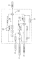
図1及び図3は本発明の実施形態1に係る自動車の電動パワーステアリング装置Aの構成を示し、1はハンドル(ステアリングホイール)、2は該ハンドル1に連結されてハンドル1の回転力(操舵力)を伝達するステアリングシャフト、3は該ステアリングシャフト2に自在継ぎ手を介して連結された中間シャフト、4は該中間シャフト3の下端に設けられたステアリングギヤボックス、5は該ステアリングギヤボックス4の両側に配設されたタイロッド、6は該各タイロッド5が連結される操舵輪としての前車輪(タイヤ)である。
【0024】
尚、図3は車両を左右一側の2輪モデルで示しており、7は後車輪、Lfは前車輪6から車両の重心位置Pまでの距離、Lrは後車輪7から車両の重心位置Pまでの距離である。
【0025】
上記ステアリングギヤボックス4内には、ラック及びそれに噛合されるピニオン(いずれも図示せず)からなるラックピニオン機構8(図3参照)が設けられており、そのピニオンには上記中間シャフト3の下端が連結されている一方、ラックの両端部は各タイロッド5を介して前車輪6に連結されている。
【0026】
上記ステアリングギヤボックス4には、そのピニオン側に減速ギヤ機構10を介して力を付与する電動モータ11と、トーションバーとしてのトルクセンサ12とが設けられ、このトルクセンサ12は上記中間シャフト3と減速ギヤ機構10との間に配設されている。これにより、上記トルクセンサ12は、ハンドル1と前車輪6との間に設けられてハンドル操舵トルクを検出するものとなっている。
【0027】
上記トルクセンサ12及び電動モータ11はそれぞれコントローラ15に接続されていて、このコントローラ15によって電動モータ11が制御される。図2に示すように、このコントローラ15には、上記トルクセンサ12、車両に生じた横加速度Gを検出する横加速度センサ16、及び電動モータ11の回転速度を検出するモータ回転速度センサ17の各検出値が入力されるようになっている。尚、上記モータ回転速度センサ17は、電動モータ11の回転速度ωを直接的に検出するものとしてもよいし、上記電動モータ11に印加される電圧等から推定するものとしてもよい。
【0028】
また、上記横加速度センサ16は、上記車両の重心位置P又はそれよりも前側に配置されている。すなわち、仮に、横加速度センサ16が車両の重心位置Pよりも後側に配置されていると、車両のオーバーステア状態で横加速度センサ16により検出される横加速度Gが重心位置Pでの横加速度により目減りし、その分、電動パワーステアリング装置Aがそれを補償しようとして前車輪6の舵角をさらに切る方向に余計にアシスト制御を行って、ハンドル1が軽くなり、オーバーステアが過度に増長されて問題が生じる。これに対し、横加速度センサ16を重心位置P又はそれよりも前側に配置することで、オーバーステア時にハンドル1の手応えの減少によりオーバーステアが増長されるのを防ぎ、アンダステア補正を行うことができる。
【0029】
図2に示す如く、上記コントローラ15には、上記トルクセンサ12の検出値が無くなるように第1制御量を決定する第1の制御部としてのアシスト制御部21と、上記トルクセンサ12の検出値から目標横加速度を演算し、この目標横加速度から、上記横加速度センサ16が検出した実際に車両に発生している横加速度を減算することによって第2制御量を決定する第2の制御部としての横加速度フィードバック制御部22と、上記アシスト制御部21及び横加速度フィードバック制御部22の各制御量を加算することによって電動モータ11の制御量を決定し、この制御量でもって電動モータ11を制御するモータ制御部23とを備えている。
【0030】
上記アシスト制御部21は、トルクセンサ12の検出値ξに対してアシスト制御ゲインKaを掛けることによって第1制御量(Ka・ξ)を決定するように構成されている。このアシスト制御ゲインKaは、車速V、トルクセンサ12の検出値ξ及び該検出値ξの微分値によって決定される非負(正又は0)の変数であって、かつ車速Vに関して非増加の(車速が高いとき(H)の方が、車速が低いとき(L)に比べて小さい)変数とされている。
【0031】
上記横加速度フィードバック制御部22は、トルクセンサ12の検出値ξの位相遅れを補償する伝達関数G1(s)を有している。この伝達関数G1(s)は、図3に示すように、ハンドルイナーシャIh,トルクセンサ12(トーションバー)の減衰係数Cb、及びそのトーションバーのばね定数Kbとして下記の式(1)で設定されている。
【0032】
G1(s)={ωh 2(Ihs2+Cbs+Kb)}/{Kb(s2+2ηhωh+ωh 2)}…(1)
ここで、sはラプラス演算子、ηh,ωhは調整パラメータである。
【0033】
そして、上記伝達関数の出力(G1(s)・ξ)によって運転者が実際にハンドル1に付与したハンドル操舵トルクuを算出するようにされている。
【0034】
また、横加速度フィードバック制御部22は、上記ハンドル操舵トルクuに含ませるフリクション成分(フリクショントルクuF)を設定するためのフリクションゲインKFを有している。このように、ハンドル操舵トルクuにフリクショントルクuFを含ませるのは、通常の自動車においては、図6に示すように、ハンドル操舵トルクuとハンドル舵角θHとの間の特性がヒステリシスになるためである。
【0035】
すなわち、このヒステリシス特性は、ステアリング系のフリクション等によって生じるものであるが、横加速度フィードバック制御部22による制御によって、そのフリクションの影響が低下し又は影響が全くなくなってしまい、同図の一点鎖線で示すように、操舵トルクuとハンドル舵角θHとの間のヒステリシス特性が失われる虞れがある。このようにハンドル操舵トルクuとハンドル舵角θHとの間の特性が通常の自動車とは異なる特性となる結果、操舵感が損われるようになる。
【0036】
そこで、操舵感の向上を目的として、予め設定した大きさのフリクショントルクuFを、目標横加速度の演算に係るハンドル操舵トルクuから減ずる(ハンドル操舵トルクuに、操舵速度方向とは逆向きにフリクショントルクuFを加える)ことで、ハンドル操舵トルクuとハンドル舵角θHとの間に、所定のヒステリシス特性が残るようにしている。
【0037】
具体的には、上記フリクションゲインKFは、図4に示すように、モータ回転速度ωの方向に応じてフリクショントルクuFの正負を設定するようになっており、モータ回転速度ω(つまりハンドル操舵速度)が正のときはフリクショントルクを+uFとし、モータ回転速度ω(つまりハンドル操舵速度)が負のときはフリクショントルクを−uFとする。尚、モータ回転速度ωがω=0(ゼロ)の点においてフリクショントルクuFが不連続になることにより、運転者の違和感を招く虞れもあるため、例えば図5に示すように、モータ回転速度ω=0点付近で、フリクショントルクuFが連続的につながるように、フリクションゲインを設定してもよい。つまり、モータ回転速度ω=0点近傍でフリクショントルクuFの絶対値を減少させてもよい。
【0038】
尚、上記フリクショントルクuFの大きさを調整することで、上記ヒステリシスの幅を調整することもできる。これにより、操舵力特性(操舵感)を常に設計どおりの特性にすることも可能になる。また、上記フリクショントルクuFは、車速Vが高いほど小さくしてもよい。こうすることで、高速走行時においては、ハンドル1の復元力が高まり、ハンドル1の戻り感を向上させることができる。さらに、上記フリクショントルクuFは、車輪舵角(前車輪6の舵角)が大きいほど小さくしてもよい。こうすることで、車輪舵角の大きい領域では車両の安定性が向上し、車輪舵角の小さい領域では車両の応答性が向上するようになる。
【0039】
上記横加速度フィードバック制御部22は、上記ハンドル操舵トルクuからフリクショントルクuFを減じた値(u−uF)に基づき目標横加速度を演算する目標ゲインKyを有し、この目標ゲインKyは、ホイールベース等の車両諸元や車速V等に基づいて予め設定されたものとなっている。すなわち、この横加速度フィードバック制御部22による制御は、ハンドル操舵トルクに対する車両応答が線形である領域(車両応答の線形領域)を対象としている。尚、この目標ゲインKyの詳細については後述する。
【0040】
また、上記横加速度フィードバック制御部22は、上記横加速度センサ16が検出した実際の横加速度Gを上記目標横加速度から減算し、この偏差(Ky(G1(s)・ξ−uF)−G)に対して制御ゲインC(s)を掛けて制御量(第2制御量)を決定するように構成されている。上記制御ゲインC(s)は式(2)で設定されている。
【0041】
C(s)=ΣBmsm/ΣAnsn …(2)
尚、m=0,1,2,…,M、n=0,1,2,…,Nである。
【0042】
このC(s)は、例えば目標横加速度と実際の横加速度Gとの偏差を0にするためのPID制御理論の伝達関数としてもよく、PID制御の場合では、
A0=0,A1=1,B0=積分ゲイン,B1=比例ゲイン,B2=微分ゲイン
とすればよい。また、上記C(s)は、PID制御以外の制御理論を用いた伝達関数としてもよい。
【0043】
上記横加速度フィードバック制御部22の制御量の感度調整(目標ゲインKy又は制御ゲインC(s)の調整)は次の▲1▼〜▲7▼のようにするのがよい。
【0044】
▲1▼ 車速Vが所定車速以下のときは、目標ゲインKyをKy=0とするのがよい。これは次の理由によるものである。つまり、ハンドル1が操舵されることによりトルクセンサ12の検出値から目標横加速度が演算されるが、例えば低速旋回時は車両に横加速度が発生し難い(又は発生しない)。このため、低速旋回時において上記目標横加速度となるように電動モータ11を制御しても、目標横加速度が達成されないという不具合が生じる。従って、車速Vが所定車速以下のときは目標ゲインKyを0として、上記横加速度フィードバック制御部22における制御を行わないのがよい。これにより、車速Vが所定車速以下のときは、アシスト制御部21による制御のみが行われる。
【0045】
一方、車速Vが所定車速以上のときは、上記アシスト制御部21のアシストゲインKaをKa=0として、横加速度フィードバック制御部22による制御のみを行うようにするのがよい。これは、上記アシスト制御部21と横加速度フィードバック制御部22とで制御干渉が起きる虞れがあるためである。
【0046】
▲2▼ 車速Vが高いほど制御ゲインC(s)を上げるのがよい。これは、高速走行時の直進安定性を向上させるためである。すなわち、例えば横風や路面不整等によって車両に外乱が入力された場合には、運転者がハンドル1の操舵をしていない、つまりハンドル操舵トルクが0であるにも拘わらず、車両に横加速度が生じることになる。しかし、横加速度フィードバック制御部22の制御は、ハンドル操舵トルクが0、すなわち目標横加速度が0であれば、直進状態を維持しようとする制御になるため、車速Vが高いほど制御ゲインC(s)を高めることで、高速走行時の直進安定性が向上する。尚、上記制御ゲインC(s)の調整は、An,Bmを変更することによって行ってもよい(式(2)参照)。
【0047】
▲3▼ 車速Vがさらに高くなって所定車速以上になれば、その車速Vが高いほど目標ゲインKyを下げるのがよい。これは、高速走行時におけるハンドル1の操舵に対する車両挙動を鈍くするためである。すなわち、中速域では、ハンドル1の操舵に対して車両挙動(横加速度挙動)が敏感に反応する方が、例えば回頭性が向上することになるため好ましいが、高速域では、ハンドル1の操舵に対して、横加速度挙動が敏感に反応するのは、挙動が不安定になってしまう虞れがあるとともに、運転者に違和感を与えてしまうことになる。そこで、車速Vがさらに高くなれば、すなわち高速走行時には目標ゲインKyを下げてハンドル1の操舵に対する車両挙動を鈍くするのが好ましい。
【0048】
よって、上記▲1▼〜▲3▼によると、車速Vの低速域では、横加速度フィードバック制御部22による制御が行われない一方、中速域(M)では、上記横加速度フィードバック制御部22による制御が積極的に行われる。そして、高速域(H)では、中速域に比べて横加速度フィードバック制御部22による制御が抑制されることとなる。
【0049】
▲4▼ 路面μ(路面摩擦係数)が低いほど目標ゲインKyを下げるのがよい。これは、路面μが低いときはタイヤ反力が小さいため、トルクセンサ12が値を検出しないか又はその検出値が小さいにも拘わらず、車両には横加速度が発生する。このため、目標横加速度と実際の横加速度Gとが合わなくなってしまうことから、路面μが低いほど目標ゲインKyを下げて、目標横加速度の影響を小さくするのが好ましい。
【0050】
▲5▼ 前車輪6の舵角(車輪舵角)が小さいほど目標ゲインKyを上げるのがよい。これは、直進安定性のより一層の向上を図るためである。
【0051】
▲6▼ 前車輪6の舵角速度(車輪舵角速度)が大きいほど目標ゲインKyを上げるのがよい。これは、車輪舵角速度が大きいときはイナーシャが大きくなってハンドル1の操舵に対して車両挙動が遅れやすくなるため、電動モータ11に大きなモータ推力を与えた方が好ましくなるためである。
【0052】
▲7▼ 車重が重いほど目標ゲインKyを上げるのがよい。つまり、例えば積載量が増えて車重が重くなっている場合のように、ハンドル1の操舵に対する車両の挙動が遅れるような場合であっても、目標ゲインKyを上げることで、電動モータ11に大きなモータ推力を与えることができて好ましい。
【0053】
尚、上記▲1▼,▲3▼〜▲7▼については、目標ゲインKyを調整しているが、制御ゲインC(s)を調整するようにしてもよい。逆に、上記▲2▼については、制御ゲインC(s)を調整しているが、目標ゲインKyを調整するようにしてもよい。
【0054】
上記横加速度フィードバック制御部22はまた、所定の仮想的なモデルにおいて、電動モータ11の出力と、トルクセンサ12を介してハンドル1から前車輪6に伝達されるトルクとの和に対するモータ回転速度を算出するための伝達関数G4(s)を有しているとともに、上記所定の仮想的なモデルにおけるモータ回転速度(舵角速度)と、実際のモータ回転速度ωとの偏差から、横加速度フィードバック制御部22の制御量を補正する補正量を算出するための伝達関数G5(s)を有している。
【0055】
上記伝達関数G4(s)は式(3)で設定されている。
【0056】
G4(s)=ΣPksk/ΣQlsl …(3)
尚、k=0,1,2,…,K、l=0,1,2,…,Lである。また、Pk,Qlは車速Vに応じて変更してもよく、車速Vに応じて段階的に変更してもよい。このとき、低車速ほどPk,Qlを細かく変更してもよい(低車速ほど、車速Vの変化に対してPk,Qlを頻繁に変更してもよい)。
【0057】
一方、上記伝達関数G5(s)は式(4)で設定されている。
【0058】
G5(s)=ωjKw/(s+ωj) …(4)
尚、ωj,Kwは調整パラメータである。
【0059】
これら伝達関数G4(s),G5(s)により、電動モータ11にダンピングを与えて、安定性を高めるようにしている。
【0060】
このようにして、アシスト制御部21及び横加速度フィードバック制御部22において各制御量が決定されれば、モータ制御部23において、上記アシスト制御部21及び横加速度フィードバック制御部22の制御量を加算して、電動モータ11を制御するためのモータ制御量を決定する。
【0061】
そして、上記モータ制御部23は補正部24を有しており、この補正部24は、ハンドル1と前車輪6との間でトルクセンサ12を介して伝達されるトルクが打ち消されるように、上記モータ制御量の補正をするものである。
【0062】
上記補正部24は、車速Vに応じて設定される第1ゲインK1と、ハンドル舵角θH及びハンドル舵角速度θH′に応じて設定される第2ゲインK2と、トルクセンサ12の検出値から上記ハンドル1と前車輪6との間で上記トルクセンサ12を介して伝達されるトルク成分を演算するための伝達関数G3(s)とを備えている。
【0063】
上記第1ゲインK1は、図7に示すように、車速Vが第1車速V1以下のときには0であり、第1車速V1よりも高いときには、車速Vの増加に応じて増加し、さらに、第2車速V2以上のときには、車速Vに拘わらず一定となるように設定されている。これにより、車両が停止しているとき又は低速走行時には、モータ制御量の補正が行われない。尚、第1車速V1と第2車速V2との間において、第1ゲインK1を連続的に変化させなくても、第1車速V1において不連続となるように第1ゲインK1を設定してもよい。
【0064】
一方、第2ゲインK2は、図8に示すように、ハンドル舵角θHが第1舵角θ1以下のときには、その舵角θHに拘わらず一定値であり、上記第1舵角θ1よりも大きいときには、舵角θHの増大に応じて減少し、さらに、第2舵角θ2よりも大きいときには0になるように設定されている。これにより、ハンドル舵角θHが第2舵角θ2よりも大きいときには、モータ制御量の補正が行われない。尚、第1舵角θ1と第2舵角θ2との間において、第2ゲインK2を連続的に変化させなくても、第1舵角θ1において不連続となるように第2ゲインK2を設定してもよい。
【0065】
また、上記第2舵角θ2は舵角速度θH′に応じて設定され、舵角速度θH′が高くなるほど第2舵角θ2が小さく設定される(同図の一点鎖線参照)。
【0066】
また、上記伝達関数G3(s)は式(5)で設定されている。
【0067】
G3(s)=ωi(Cbs+Kb)/{Kb(s+ηiωi)} …(5)
ここで、ωi,ηiは調整パラメータである。
【0068】
こうして第1ゲインK1、第2ゲインK2及び伝達関数G3(s)によって、ハンドル1と前車輪6との間でトルクセンサ12を介して伝達されるトルク成分を演算し、これをモータ制御量から減算する補正を行う。
【0069】
したがって、上記実施形態においては、トルクセンサ12の値から目標となる目標横加速度を演算し、この目標横加速度となるように電動モータ11が制御される。このため、アシスト制御部21の制御量(Ka・ξ)で電動モータ11を制御することによって所望の横加速度が発生しない場合であっても、横加速度フィードバック制御部22の制御によって、目標横加速度(所望の横加速度)が車両に生じる。
【0070】
こうして、目標横加速度となるように電動モータ11が制御されることで、たとえフリクションやイナーシャの大きさが異なる場合であっても、運転者のハンドル1の操舵(ハンドル操舵トルク)に対して、常に所望の横加速度が車両に生じるようになる。これにより、操舵フィーリングの向上や違和感の軽減が図られ、運転者の疲労を軽減することができる。
【0071】
また、例えば積載量が増えて車重が重くなっている場合のような、ハンドル1の操舵に対する車両の挙動が遅れるような場合であっても、目標横加速度と実際の横加速度との偏差に基づいて電動モータ11の制御が行われるため、車重の如何に拘わらず、ハンドル1の操舵に対して、常に所望の横加速度が車両に生じるようになる。つまり、常に同様の操舵フィーリングが得られる。
【0072】
さらに、例えば車両が直進状態であるときに、横風や路面不整等によって車両に横加速度が生じた場合には、横加速度フィードバック制御部22は目標横加速度を0とする制御、すなわち直進状態を維持しようとする制御を行う。このため、上記横風や路面不整等の外乱に対する直進安定性の向上が図られる。
【0073】
そして、上記モータ制御部23は、ハンドル1と前車輪6との間でトルクセンサ12を介して伝達されるトルク(推定トルク)を推定するとともに、この推定トルクをモータ制御量から減算する補正部24を有している。この補正部24によりモータ制御量が補正されることで、ハンドル1から前車輪6に実際に伝達されるトルクと上記推定トルクとが相殺されることになり、制御上は、ハンドル1から前車輪6にトルクが伝達されないことになる。こうして、特に車両が外乱を受けたときに、運転者によるハンドル1の操舵と、横加速度フィードバック制御部22における制御とが干渉してしまうことを回避することができる。
【0074】
また、上記補正部24においては、第1車速V1以下のときには第1ゲインK1を0としかつ、第1車速V1よりも車速Vが高いときには車速Vに応じて第1ゲインK1を高めることで、モータ制御量の補正の禁止・実行を切り換えるように構成されている。こうすることで、不必要なモータ制御量の補正を回避しつつ、制御干渉を回避することができる。
【0075】
つまり、第1車速V1以下のときの停車時又は低速走行時には、車両に横加速度が発生しないか又は発生し難いため、上記コントローラ15においては、目標ゲインKyを0として横加速度フィードバック制御部22における制御を行わず、中速又は高速走行時に目標ゲインKyを比較的高めるようにしている。一方、アシスト制御ゲインKaは、図7の一点鎖線で示すように、停車時又は低速走行時に高める一方、中速又は高速走行時には低下させるようにしている。
【0076】
ここで、横加速度フィードバック制御部22による制御を行わないときは、この横加速度フィードバック制御部22の制御に対する干渉の問題が生じないとともに、元々停車時又は低速走行時には、車両に対する外乱の影響自体がない。また逆に、横加速度フィードバック制御部22による制御を行わないときに、補正部24によるモータ制御量の補正を行うと、トルクセンサ12を介して伝達されるトルクを打ち消す制御が行われることになるため、運転者によるハンドル操舵トルクが前車輪6にまで伝わらず舵が切れなくなることにもなる。
【0077】
そこで、車速Vが第1車速V1以下であるとき、言い換えると横加速度フィードバック制御部22の制御感度が0のときには、モータ制御量の補正を禁止することで、上記の不都合が回避される。一方、車速Vが第1車速V1よりも高いときには、言い換えるとアシスト制御部21の制御感度が低く、逆に横加速度フィードバック制御部22の制御感度が高いときには、モータ制御量の補正を行うことで、制御干渉が回避される。
【0078】
さらに、上記補正部24においては、第2舵角θ2を閾値としてモータ制御量の補正の禁止・実行を切り換えるように構成されている。こうすることで、制御干渉を回避しつつ、横加速度フィードバック制御部22による制御が有効に行われない車両応答の非線形領域では、前車輪6等の状態を操舵反力として運転者に的確に伝えることができる。
【0079】
すなわち、上述したように、横加速度フィードバック制御部22は、車両応答の線形領域における制御を行うように構成されている。このため、ハンドル舵角θHが第2舵角θ2以下である車両応答の線形領域では、モータ制御量の補正を行うことで、制御干渉を回避することができる一方、第2制御量による制御が有効でない車両応答の非線形領域(ハンドル舵角θHが第2舵角θ2よりも大きいとき)では、モータ制御量の補正を禁止することで前車輪6からハンドル1にトルクを伝達させ、これにより、前車輪6等の状態を操舵反力として運転者に的確に伝えることができる。
【0080】
また、補正部24におけるモータ制御量の補正の禁止・実行の閾値である第2舵角θ2を、ハンドル舵角速度θH′が高くなるほど小さくすることで、車両応答の線形領域が狭くなることに対応して、モータ制御量の補正の禁止・実行の切換えがなされ、車両応答の線形領域では、制御干渉を回避しつつ、横加速度フィードバック制御部22による制御によって所望の横加速度を発生させる一方、車両応答の非線形領域では、前車輪6等の状態を操舵反力として運転者に的確に伝えることができるようになる。
【0081】
(実施形態2)
図9は実施形態2を示し(図1〜図8と同じ部分については同じ符号を付してその詳細な説明は省略する)、上記実施形態1では、第2の制御部としての横加速度フィードバック制御部22において、トルクセンサ12の検出値を基に演算した目標横加速度から実際の横加速度Gを減算することによって電動モータ11の第2制御量を決定するようにしているのに対し、トルクセンサ12の検出値を基に演算した目標横滑り角から推定横滑り角βを減算することによって電動モータ11の第2制御量を決定するようにしたものである。
【0082】
すなわち、この実施形態2におけるコントローラ15には、実施形態1と同様のトルクセンサ12、横加速度センサ16及びモータ回転速度センサ17に加え、さらに、車両に生じたヨーレートを検出するヨーレートセンサ18の各検出値が入力されるようになっている。
【0083】
また、コントローラ15には、トルクセンサ12の検出値が無くなるように第1制御量を決定する第1の制御部としてのアシスト制御部21と、トルクセンサ12の検出値から目標横滑り角を演算し、この目標横滑り角から、横滑り角推定部28において推定された推定横滑り角βを減算することによって第2制御量を決定する第2の制御部としての横滑り角フィードバック制御部27と、上記アシスト制御部21及び横滑り角フィードバック制御部27の各制御量を加算することによって電動モータ11の制御量を決定し、この制御量でもって電動モータ11を制御するモータ制御部23とを備えている。
【0084】
上記横滑り角推定部28は、上記横加速度センサ16が検出した実際に車両に発生している横加速度Gと、ヨーレートセンサ18が検出した実際に車両に発生しているヨーレートψとから横滑り角βを演算により推定するもので、その推定横滑り角βの演算は式(6)により行う。
【0085】
β=∫{(G+r・ψ″)/V+ψ′}dt …(6)
ここで、rは車両の重心位置Pからその前側にある横加速度センサ16の位置までの距離である。横加速度センサ16が車両の重心位置Pにある場合には、r=0であるので、式(6)は、
β=∫{(G/V)+ψ′}dt
となる。
【0086】
上記横滑り角フィードバック制御部27は、上記ハンドル操舵トルクuからフリクショントルクuFを減じた値(u−uF)に基づいて目標横滑り角を演算する目標ゲインKyを有し、この目標ゲインKyは、ホイールベース等の車両諸元や車速V等に基づいて予め設定される。
【0087】
また、上記横滑り角フィードバック制御部27は、上記目標横滑り角から、上記横滑り角推定部28において演算された推定横滑り角βを減算し、この偏差(Ky(G1(s)・ξ−uF)−β)に対して制御ゲインC(s)を掛けて制御量(第2制御量)を決定するように構成されている。上記制御ゲインC(s)は上記式(2)で設定される。
【0088】
このC(s)は、例えば目標横滑り角と実際の推定横滑り角βとの偏差を0にするためのPID制御理論の伝達関数としてもよく、PID制御以外の制御理論を用いた伝達関数としてもよい。
【0089】
その他の構成は上記実施形態1と同様であるので、その詳細な説明は省略する。
【0090】
したがって、この実施形態の場合、トルクセンサ12の値から目標となる目標横滑り角を演算し、この目標横滑り角となるように電動モータ11が制御される。このため、アシスト制御部21の制御量で電動モータ11を制御することによって、所望の横滑り角が発生しない場合であっても、横滑り角フィードバック制御部27の制御によって、目標横滑り角(所望の横滑り角)が車両に生じる。このように目標横滑り角となるように電動モータ11が制御されることで、たとえフリクションやイナーシャの大きさが異なる場合であっても、運転者のハンドル1の操舵(ハンドル操舵トルク)に対して、常に所望の横滑り角が車両に生じるようになる。よって、上記実施形態1と同様の作用効果を奏することができる。
【0091】
【発明の効果】
以上説明したように、請求項1〜9の発明の自動車の電動パワーステアリング装置によると、目標横加速度又は車体重心点の目標横滑り角に基づく第2制御量でもって電動モータが制御されるため、フリクションやイナーシャの大きさに拘わらず、ハンドル操舵に対して常に所望の車両挙動を得ることができ、例えば製品間での性能差を無くすことができるとともに、車両に対して外乱が入力されても、第2の制御部によって、直進状態を維持しようとする制御が行われるため、直進安定性を向上させることができ、よって、運転者の操舵フィーリングの悪化や違和感を防止することができる。
【0092】
加えて、請求項2〜9の発明によれば、第2制御量の感度を車速、路面摩擦係数、車輪舵角及び車輪舵角速度に応じて調整することによって、より一層好ましい電動パワーステアリング装置が構成される。
【図面の簡単な説明】
【図1】本発明の実施形態1に係る電動パワーステアリング装置の構成を示す斜視図である。
【図2】コントローラの構成を示すブロック図である。
【図3】電動パワーステアリング装置の構成を示すブロック図である。
【図4】フリクションゲインの一例を示す図である。
【図5】図4とは異なるフリクションゲインの一例を示す図である。
【図6】ハンドル操舵トルクとハンドル舵角との関係を示す図である。
【図7】補正部における第1ゲインの特性を示す図である。
【図8】補正部における第2ゲインの特性を示す図である。
【図9】実施形態2に係るコントローラの構成を示す図2相当図である。
【符号の説明】
A 電動パワーステアリング装置
1 ハンドル
6 前車輪(車輪)
11 電動モータ
12 トルクセンサ
15 コントローラ
16 横加速度センサ
17 モータ回転速度センサ
18 ヨーレートセンサ
21 アシスト制御部(第1の制御部)
22 横加速度フィードバック制御部(第2の制御部)
23 モータ制御部
27 横滑り角フィードバック制御部(第2の制御部)
28 横滑り角推定部
P 重心位置
V 車速
ξ トルクセンサ検出値
u ハンドル操舵トルク
G 横加速度
β 横滑り角[0001]
BACKGROUND OF THE INVENTION
The present invention belongs to a technical field relating to an electric power steering apparatus that assists steering of a vehicle by controlling an electric motor. In the present invention, an automobile is also referred to as a “vehicle”.
[0002]
[Prior art]
2. Description of the Related Art Conventionally, as a power steering apparatus for an automobile, an apparatus that assists steering by an electric motor or hydraulic pressure is known. In this apparatus, depending on steering torque or steering speed (differential value of steering angle). The control amount or hydraulic pressure of the electric motor is adjusted to achieve a predetermined assist characteristic. Further, there are known ones that change the assist characteristic according to, for example, the vehicle speed, and those that change according to the lateral acceleration and the yaw rate in addition to the vehicle speed (see, for example, Japanese Patent Laid-Open No. 8-72734).
[0003]
[Problems to be solved by the invention]
By the way, in an electric power steering apparatus using a conventional electric motor, a torque sensor (torsion bar) that is provided between a steering wheel and a wheel (steering wheel) and detects a steering torque of the steering wheel is usually provided. Is multiplied by a predetermined gain (assist control gain) to determine the control amount of the electric motor. The value of the assist control gain is adjusted so that a desired assist characteristic is obtained based on a test performed on a predetermined automobile.
[0004]
However, in this electric power steering apparatus, for example, for each product, the lateral acceleration and the skid angle as the behavior of the vehicle generated with respect to the steering force vary, and the desired lateral acceleration and the skid angle with respect to the steering force vary in the vehicle. It may not occur. In this case, it is necessary for the driver to adjust the steering force so as to obtain a desired lateral acceleration and side slip angle.
[0005]
This variation in lateral acceleration and sideslip angle varies, for example, in the magnitude of inertia, or in the magnitude of friction in an electric motor or a reduction gear mechanism provided between the electric motor and the steering shaft. There is a cause. For example, the variation in the magnitude of friction is mainly caused by manufacturing errors of parts, and when the friction is larger than usual, the control amount obtained by multiplying the detection value of the torque sensor by a predetermined gain. Even if the electric motor is controlled in this way, the motor thrust is consumed by friction, and the driver must increase the steering force because the auxiliary steering force by the electric motor is insufficient.
[0006]
In addition, the case where the desired lateral acceleration or side slip angle does not occur with respect to the steering of the driver's steering wheel is not limited to the above-described variation in the magnitude of the inertia and the friction. When the steering force is 0), a lateral acceleration or a side slip angle may occur in the vehicle due to a disturbance to the vehicle such as a side wind or a road surface irregularity. Also in this case, the driver needs to achieve a desired vehicle behavior by adjusting the steering wheel.
[0007]
As described above, there is a problem in that a desired lateral acceleration and a skid angle are not generated with respect to steering of the steering wheel, thereby causing a driver's steering feeling to deteriorate and a sense of incongruity, leading to driver fatigue.
[0008]
SUMMARY OF THE INVENTION The present invention has been made in view of such a point, and an object of the present invention is, as described above, in an electric power steering apparatus for an automobile that assists steering with a steering by controlling an electric motor. Is always made to have a desired behavior.
[0009]
[Means for Solving the Problems]
In order to achieve the above object, according to the present invention, feedback control based on the detection value of the torque sensor is performed in addition to the assist control in the conventional electric power steering apparatus.
[0012]
Specifically, according to the first aspect of the present invention, a torque sensor is provided between the steering wheel and the wheel and detects the steering torque of the steering wheel as an electric power steering device for an automobile that assists steering by controlling the electric motor. A first control unit that determines the first control amount of the electric motor so that the detection value of the torque sensor is eliminated, and the detection value of the torque sensorOf the center of gravityThe target skid angle was calculated and estimated from the target skid angle.Of the center of gravityThe second control unit that determines the second control amount of the electric motor by subtracting the estimated side slip angle, the first control amount by the first control unit, and the second control amount by the second control unit are added. And a motor control unit that controls the electric motor based on the controlled amount.
[0013]
thisAccording to the configuration of the invention, as the steering wheel is steered, a torque sensor provided between the steering wheel and the wheel detects the steering wheel torque, and the first control unit eliminates the detected value of the torque sensor. That is, the first control amount is determined by multiplying the detection value of the torque sensor by a predetermined gain. This corresponds to the conventional assist control.
[0014]
On the other hand, in the second control unit, from the detection value of the torque sensor.Of the center of gravityThe target skid angle was calculated and estimated from this target skid angle.Of the center of gravityThe second control amount is determined by subtracting the estimated side slip angle. here,Of the center of gravityThe target side slip angle may be calculated using a map (gain) with respect to the steering wheel torque set in advance based on vehicle specifications such as a wheel base, vehicle speed, and the like.
[0015]
The motor control unit controls the electric motor with a control amount obtained by adding the first control amount and the second control amount. Here, even if the electric motor is controlled with the first control amount, the desired vehicle behavior (Of the center of gravityWhen the side slip angle does not occur, the calculation is based on the detection value of the torque sensor.Of the center of gravityTarget skid angle andOf the center of gravityA deviation from the estimated skid angle has occurred. For this reason, by controlling the electric motor with the second control amount determined by this deviation,Of the center of gravityThe desired skid angle is produced in the vehicle.
[0016]
in this way,Of the center of gravityBy controlling the electric motor to achieve the target side slip angle, even if the size of the inertia and the size of the friction of the components that make up the electric power steering device vary, the driver's handle operation (handle steering torque) Always againstOf the center of gravityThe desired skid angle will occur in the vehicle. Thereby, improvement of steering feeling and reduction of a sense of incongruity are achieved.
[0017]
For example, when the vehicle is in a straight traveling state, the steering wheel torque is 0 because the driver is not steering the steering wheel. For this reason, it is difficult toOf the center of gravityWhen a skid angle occurs, the second control unitOf the center of gravitySince the control for setting the target side slip angle to 0, that is, the control for maintaining the straight running state, is performed, the straight running stability against the disturbance such as the side wind and road surface irregularity can be improved. This eliminates the need for the driver to adjust the steering wheel, thereby reducing the driver's fatigue.
[0018]
Claims above1In the electric power steering device for an automobile according to the present invention, more preferable control is realized by adjusting the sensitivity of the second control amount. Specifically, the claims2As in the invention, the second control unit is preferably configured to increase the sensitivity of the second control amount as the vehicle speed increases. In other words, in a region where the vehicle speed is high, the driver quickly turns the steering angle in small increments, and therefore, it is preferable to increase the sensitivity of the second control amount because the driver is worried about being caught by friction. On the other hand, in the low vehicle speed range, the driver turns the steering angle slowly and slowly, so it does not bother with friction and the like, and at low speeds it requires a large amount of thrust and consumes more energy. It is not preferable to increase the value.
[0019]
Claims3As in the invention, it is preferable that the second control unit lowers the sensitivity of the second control amount as the road surface friction coefficient is lower. That is, when the road surface friction coefficient is low, stability is desired. However, when the sensitivity of the second control amount is high, the behavior of the vehicle becomes fast and uncomfortable. Further, when the road surface friction coefficient is low, the force that can be generated by the wheel is also small, so that even if the sensitivity of the second control amount is increased, the vehicle cannot follow, and in some cases, the control oscillates.
[0021]
In addition, the claims4As in the invention, it is preferable that the second control unit increases the sensitivity of the second control amount as the wheel steering angle is smaller. That is, the region where the wheel rudder angle is small is a region where the steering wheel is steered little by little in order to maintain the straightness of the vehicle, and it is possible to prevent catching and the like by increasing the sensitivity of the second control amount in this region. is necessary. In addition, there is no noticeable problem in the region where the rudder angle is large, and there is a difference from the model entering the nonlinear region of the wheel. From this point of view, it is uncomfortable to reduce the sensitivity of the second control amount. Can be reduced.
[0022]
Claims5As in the invention, the second control unit is preferably configured to increase the sensitivity of the second control amount as the wheel steering angular speed increases. That is, as the rudder angular velocity increases, the followability and the feeling of catching become more prominent, so it is preferable to increase the sensitivity of the second control amount.
According to a sixth aspect of the present invention, there is provided an electric power steering apparatus for an automobile which assists steering of a steering wheel by controlling an electric motor, and is provided between a steering wheel and a wheel and detects a steering torque of the steering wheel. A first control unit that determines the first control amount of the electric motor so that the detected value of the electric motor is eliminated, and a target lateral acceleration is calculated from the detected value of the torque sensor, and is actually generated in the vehicle from the target lateral acceleration. A second control unit that determines a second control amount of the electric motor by subtracting the lateral acceleration, a first control amount by the first control unit, and a second control amount by the second control unit. And a motor control unit that controls the electric motor based on the added control amount. The second control unit is configured to increase the sensitivity of the second control amount as the vehicle speed increases.
According to the configuration of the present invention, as in the first aspect of the invention, as the steering wheel is steered, the torque sensor provided between the steering wheel and the wheel detects the steering torque of the steering wheel. The first control amount is determined such that the detection value of the torque sensor is eliminated, that is, the detection value of the torque sensor is multiplied by a predetermined gain. This corresponds to the conventional assist control.
On the other hand, in the second control unit, the target lateral acceleration is calculated from the detected value of the torque sensor, and the second control amount is determined by subtracting the lateral acceleration actually generated in the vehicle from the target lateral acceleration. The Here, the target lateral acceleration may be calculated by a map (gain) with respect to the steering wheel torque set in advance based on vehicle specifications such as a wheel base, vehicle speed, and the like.
The motor control unit controls the electric motor with a control amount obtained by adding the first control amount and the second control amount. Here, if the desired vehicle behavior (lateral acceleration) is not obtained even when the electric motor is controlled with the first control amount, the deviation between the target lateral acceleration calculated based on the detected value of the torque sensor and the actual lateral acceleration. Will have occurred. For this reason, a desired lateral acceleration is generated in the vehicle by controlling the electric motor with the second control amount determined by this deviation.
Thus, by controlling the electric motor to achieve the target lateral acceleration, even if the magnitude of the inertia and the magnitude of the friction of the components constituting the electric power steering device vary, the driver's steering operation ( A desired lateral acceleration always occurs in the vehicle with respect to the steering torque. Thereby, improvement of steering feeling and reduction of a sense of incongruity are achieved.
For example, when the vehicle is in a straight traveling state, the steering wheel torque is 0 because the driver is not steering the steering wheel. For this reason, when a lateral acceleration occurs in the vehicle due to a crosswind or a road surface irregularity, the second control unit performs a control for setting the target lateral acceleration to 0, that is, a control for maintaining a straight traveling state. It is possible to improve straight running stability against disturbances such as crosswinds and road surface irregularities. This eliminates the need for the driver to adjust the steering wheel, thereby reducing the driver's fatigue.
And since the 2nd control part is comprised so that the sensitivity of 2nd control amount may be raised, so that vehicle speed is high, the effect similar to the invention of the said
According to the seventh aspect of the present invention, as an electric power steering device for an automobile which assists steering of the steering wheel by controlling the electric motor, the torque sensor, the first control unit, the second A control unit and a motor control unit are provided. And the 2nd control part is comprised so that the sensitivity of a 2nd control amount may be reduced, so that a road surface friction coefficient is low.
In this invention, the same effect as that of the invention of
According to an eighth aspect of the present invention, there is provided a torque sensor similar to the sixth aspect of the invention as an electric power steering device for an automobile configured to assist steering by controlling an electric motor. A first control unit, a second control unit, and a motor control unit are provided. And the 2nd control part is comprised so that the sensitivity of 2nd control amount may be raised, so that a wheel steering angle is small.
In this invention, the same effect as that of the invention of
According to the ninth aspect of the present invention, as an electric power steering device for an automobile that assists steering of the steering wheel by controlling the electric motor, the torque sensor, the first control unit, A control unit and a motor control unit are provided. And the 2nd control part is comprised so that the sensitivity of 2nd control amount may be raised, so that wheel steering angular velocity is large.
In this invention, the same effect as that of the invention of
[0023]
DETAILED DESCRIPTION OF THE INVENTION
(Embodiment 1)
1 and 3 show the configuration of an electric power steering apparatus A for an automobile according to
[0024]
FIG. 3 shows the vehicle as a two-wheel model on the left and right sides, where 7 is the rear wheel, Lf is the distance from the
[0025]
The
[0026]
The
[0027]
The
[0028]
The lateral acceleration sensor 16 is disposed at the center of gravity position P of the vehicle or in front of it. That is, if the lateral acceleration sensor 16 is arranged behind the center of gravity position P of the vehicle, the lateral acceleration G detected by the lateral acceleration sensor 16 in the oversteer state of the vehicle is the lateral acceleration at the center of gravity position P. As a result, the electric power steering device A tries to compensate for it, and performs extra assist control in the direction of further turning the rudder angle of the
[0029]
As shown in FIG. 2, the
[0030]
The
[0031]
The lateral
[0032]
G1(s) = {ωh 2(Ihs2+ Cbs + Kb)} / {Kb(S2+ 2ηhωh+ Ωh 2)} ... (1)
Where s is the Laplace operator and ηh, ΩhIs an adjustment parameter.
[0033]
The output of the transfer function (G1The steering wheel torque u actually applied to the
[0034]
Further, the lateral acceleration
[0035]
In other words, this hysteresis characteristic is caused by the friction of the steering system, etc., but the influence of the friction is reduced or completely eliminated by the control by the lateral acceleration
[0036]
Therefore, for the purpose of improving the steering feeling, the friction torque u having a preset size is used.FIs reduced from the steering wheel torque u related to the calculation of the target lateral acceleration (the friction torque u in the steering wheel torque u in the direction opposite to the steering speed direction).FThe steering wheel steering torque u and the steering wheel steering angle θ.HA predetermined hysteresis characteristic remains between the two.
[0037]
Specifically, the friction gain KFAs shown in FIG. 4, the friction torque u depends on the direction of the motor rotational speed ω.FWhen the motor rotation speed ω (that is, the steering wheel steering speed) is positive, the friction torque is set to + uFWhen the motor rotation speed ω (that is, the steering speed of the steering wheel) is negative, the friction torque is −uFAnd Note that the friction torque u at the point where the motor rotational speed ω is ω = 0 (zero).FSince the discontinuity may cause a driver's uncomfortable feeling, for example, as shown in FIG. 5, the friction torque u near the motor rotational speed ω = 0 point.FThe friction gain may be set so that are continuously connected. That is, the friction torque u near the motor rotational speed ω = 0 point.FThe absolute value of may be decreased.
[0038]
The friction torque uFThe width of the hysteresis can be adjusted by adjusting the size of. As a result, the steering force characteristic (steering feeling) can always be made as designed. The friction torque uFMay be smaller as the vehicle speed V is higher. By doing so, the restoring force of the
[0039]
The lateral acceleration
[0040]
Further, the lateral acceleration
[0041]
C (s) = ΣBmsm/ ΣAnsn ... (2)
Note that m = 0, 1, 2,..., M, and n = 0, 1, 2,.
[0042]
This C (s) may be, for example, a transfer function of PID control theory for setting the deviation between the target lateral acceleration and the actual lateral acceleration G to 0. In the case of PID control,
A0= 0, A1= 1, B0= Integral gain, B1= Proportional gain, B2= Differential gain
And it is sufficient. The C (s) may be a transfer function using a control theory other than PID control.
[0043]
Sensitivity adjustment of the control amount of the lateral acceleration feedback control unit 22 (target gain Ky(Or adjustment of the control gain C (s)) is preferably carried out as in the following (1) to (7).
[0044]
(1) When the vehicle speed V is less than the predetermined vehicle speed, the target gain KyKy= 0 is preferable. This is due to the following reason. That is, when the
[0045]
On the other hand, when the vehicle speed V is equal to or higher than the predetermined vehicle speed, the assist gain K of the
[0046]
(2) It is better to increase the control gain C (s) as the vehicle speed V is higher. This is to improve the straight running stability during high speed running. That is, when a disturbance is input to the vehicle due to, for example, a crosswind or road surface irregularity, the driver does not steer the
[0047]
(3) If the vehicle speed V further increases and exceeds the predetermined vehicle speed, the target gain K increases as the vehicle speed V increases.yIt is good to lower. This is to slow down the vehicle behavior with respect to steering of the
[0048]
Therefore, according to the above (1) to (3), the control by the lateral acceleration
[0049]
(4) The lower the road surface μ (road friction coefficient), the target gain KyIt is good to lower. This is because, when the road surface μ is low, the tire reaction force is small, and therefore the lateral acceleration occurs in the vehicle even though the
[0050]
(5) The smaller the rudder angle (wheel rudder angle) of the
[0051]
(6) The target gain K increases as the rudder angular velocity (wheel rudder angular velocity) of the
[0052]
▲ 7 ▼ Target gain K as the vehicle weight increasesyIt is good to raise. That is, even when the vehicle behavior with respect to steering of the
[0053]
For the above (1) and (3) to (7), the target gain KyHowever, the control gain C (s) may be adjusted. Conversely, for (2) above, the control gain C (s) is adjusted, but the target gain KyMay be adjusted.
[0054]
The lateral acceleration
[0055]
Transfer function GFour(s) is set by equation (3).
[0056]
GFour(s) = ΣPksk/ ΣQlsl ... (3)
Note that k = 0, 1, 2,..., K, l = 0, 1, 2,. Pk, QlMay be changed according to the vehicle speed V, or may be changed stepwise according to the vehicle speed V. At this time, the lower the vehicle speed, the more Pk, Ql(The lower the vehicle speed, the lower the Pk, QlMay change frequently).
[0057]
On the other hand, the transfer function GFive(s) is set by equation (4).
[0058]
GFive(s) = ωjKw/ (S + ωj(4)
Ωj, KwIs an adjustment parameter.
[0059]
These transfer functions GFour(s), GFiveAccording to (s), damping is given to the
[0060]
When the control amounts are determined in the
[0061]
The motor control unit 23 includes a
[0062]
The
[0063]
First gain K1As shown in FIG. 7, the vehicle speed V is the first
[0064]
On the other hand, the second gain K2As shown in FIG.HIs the first steering angle θ1The steering angle θHRegardless of the first steering angle θ1Is greater as the rudder angle θH decreases, and further the second rudder angle θ2When the value is larger than 0, it is set to 0. As a result, the steering angle θHIs the second steering angle θ2If it is greater than the range, the motor control amount is not corrected. The first steering angle θ1And the second steering angle θ2And the second gain K2Even without continuously changing the first steering angle θ1The second gain K so as to be discontinuous at2May be set.
[0065]
Further, the second steering angle θ2Is the rudder angular velocity θH′ Is set according to the rudder angular velocity θHAs ′ increases, the second steering angle θ2Is set to a small value (see the alternate long and short dash line in the figure).
[0066]
The transfer function GThree(s) is set by equation (5).
[0067]
GThree(s) = ωi(Cbs + Kb) / {Kb(S + ηiωi)}… (5)
Where ωi, ΗiIs an adjustment parameter.
[0068]
Thus, the first gain K1, Second gain K2And transfer function GThreeAccording to (s), a torque component transmitted between the
[0069]
Therefore, in the above embodiment, the target lateral acceleration that is a target is calculated from the value of the
[0070]
Thus, by controlling the
[0071]
Further, even when the behavior of the vehicle with respect to the steering of the
[0072]
Further, for example, when the vehicle is in a straight running state and a lateral acceleration occurs in the vehicle due to a cross wind or road surface irregularity, the lateral acceleration
[0073]
The motor control unit 23 estimates a torque (estimated torque) transmitted between the
[0074]
In the
[0075]
That is, the first vehicle speed V1When the vehicle is stopped or traveling at a low speed in the following cases, lateral acceleration does not occur or is unlikely to occur in the vehicle.yIs set to 0, the control in the lateral acceleration
[0076]
Here, when the control by the lateral acceleration
[0077]
Therefore, the vehicle speed V is the first vehicle speed V1When the following is true, in other words, when the control sensitivity of the lateral acceleration
[0078]
Further, in the
[0079]
That is, as described above, the lateral acceleration
[0080]
Further, the second steering angle θ, which is a threshold value for prohibiting / executing correction of the motor control amount in the correction unit 24.2The steering wheel steering angular velocity θHThe smaller the ′ is, the smaller the linear region of the vehicle response becomes. In response to the fact that the correction of the motor control amount is prohibited / executed, the control response is avoided in the linear region of the vehicle response. While the desired lateral acceleration is generated by the control by the lateral acceleration
[0081]
(Embodiment 2)
FIG. 9 shows a second embodiment (the same parts as those in FIGS. 1 to 8 are denoted by the same reference numerals and detailed description thereof is omitted). In the first embodiment, the lateral acceleration feedback as the second control unit is shown. In the
[0082]
That is, the
[0083]
Further, the
[0084]
The side
[0085]
β = ∫ {(G + r · ψ ″) / V + ψ ′} dt (6)
Here, r is the distance from the center of gravity position P of the vehicle to the position of the lateral acceleration sensor 16 on the front side thereof. When the lateral acceleration sensor 16 is at the center of gravity position P of the vehicle, r = 0, so that the equation (6) is
β = ∫ {(G / V) + ψ ′} dt
It becomes.
[0086]
The side slip angle
[0087]
Further, the side slip angle
[0088]
This C (s) may be a transfer function of PID control theory for setting the deviation between the target side slip angle and the actual estimated side slip angle β to 0, or may be a transfer function using a control theory other than PID control. Good.
[0089]
Since other configurations are the same as those of the first embodiment, detailed description thereof is omitted.
[0090]
Therefore, in the case of this embodiment, the target side slip angle which is a target is calculated from the value of the
[0091]
【The invention's effect】
As described above, according to the electric power steering device for an automobile of the inventions of
[0092]
In addition, the claims2-9According to the invention, the sensitivity of the second control amount is set to the vehicle speed,Road friction coefficient, wheel rudder angleAnd by adjusting according to the wheel rudder angular velocity, an even more preferable electric power steering device is configured.
[Brief description of the drawings]
FIG. 1 is a perspective view showing a configuration of an electric power steering apparatus according to
FIG. 2 is a block diagram illustrating a configuration of a controller.
FIG. 3 is a block diagram showing a configuration of an electric power steering apparatus.
FIG. 4 is a diagram illustrating an example of a friction gain.
FIG. 5 is a diagram illustrating an example of a friction gain different from that in FIG. 4;
FIG. 6 is a diagram illustrating a relationship between a steering wheel torque and a steering wheel angle.
FIG. 7 is a diagram illustrating a characteristic of a first gain in a correction unit.
FIG. 8 is a diagram illustrating characteristics of a second gain in the correction unit.
FIG. 9 is a diagram corresponding to FIG. 2 and shows the configuration of the controller according to the second embodiment.
[Explanation of symbols]
A Electric power steering device
1 Handle
6 Front wheels
11 Electric motor
12 Torque sensor
15 Controller
16 Lateral acceleration sensor
17 Motor rotation speed sensor
18 Yaw rate sensor
21 Assist control unit (first control unit)
22 Lateral acceleration feedback control unit (second control unit)
23 Motor controller
27 Side slip angle feedback control unit (second control unit)
28 Side slip angle estimation part
P Center of gravity position
V vehicle speed
ξ Torque sensor detection value
u Steering torque
G Lateral acceleration
β skid angle
Claims (9)
ハンドルと車輪との間に設けられ、ハンドル操舵トルクを検出するトルクセンサと、
上記トルクセンサの検出値が無くなるように上記電動モータの第1制御量を決定する第1の制御部と、
上記トルクセンサの検出値から車体重心点の目標横滑り角を演算し、該目標横滑り角から、演算により推定された車体重心点の推定横滑り角を減算することによって上記電動モータの第2制御量を決定する第2の制御部と、
上記第1の制御部による第1制御量と第2の制御部による第2制御量とを加算した制御量に基づいて上記電動モータを制御するモータ制御部とを備えていることを特徴とする自動車の電動パワーステアリング装置。An electric power steering device for an automobile that assists steering by controlling an electric motor,
A torque sensor provided between the steering wheel and the wheel for detecting steering steering torque;
A first control unit that determines a first control amount of the electric motor such that a detection value of the torque sensor is eliminated;
A target skid angle at the center of gravity of the vehicle body is calculated from the detected value of the torque sensor, and a second control amount of the electric motor is obtained by subtracting the estimated side slip angle of the center of gravity of the vehicle body estimated by the calculation from the target skid angle. A second control unit to determine;
And a motor control unit that controls the electric motor based on a control amount obtained by adding the first control amount by the first control unit and the second control amount by the second control unit. Electric power steering device for automobiles.
第2の制御部は、車速が高いほど第2制御量の感度を上げるように構成されていることを特徴とする自動車の電動パワーステアリング装置。The electric power steering apparatus for an automobile according to claim 1 ,
The second control unit is configured to increase the sensitivity of the second control amount as the vehicle speed increases.
第2の制御部は、路面摩擦係数が低いほど第2制御量の感度を下げるように構成されていることを特徴とする自動車の電動パワーステアリング装置。The electric power steering apparatus for an automobile according to claim 1 ,
The electric power steering device for an automobile, wherein the second control unit is configured to lower the sensitivity of the second control amount as the road surface friction coefficient is lower.
第2の制御部は、車輪舵角が小さいほど第2制御量の感度を上げるように構成されていることを特徴とする自動車の電動パワーステアリング装置。The electric power steering apparatus for an automobile according to claim 1 ,
The second control unit is configured to increase the sensitivity of the second control amount as the wheel rudder angle is smaller.
第2の制御部は、車輪舵角速度が大きいほど第2制御量の感度を上げるように構成されていることを特徴とする自動車の電動パワーステアリング装置。The electric power steering apparatus for an automobile according to claim 1 ,
The second control unit is configured to increase the sensitivity of the second control amount as the wheel steering angular speed increases, and is an electric power steering device for an automobile.
ハンドルと車輪との間に設けられ、ハンドル操舵トルクを検出するトルクセンサと、A torque sensor provided between the handle and the wheel for detecting the steering torque of the handle;
上記トルクセンサの検出値が無くなるように上記電動モータの第1制御量を決定する第1の制御部と、A first control unit that determines a first control amount of the electric motor such that a detection value of the torque sensor is eliminated;
上記トルクセンサの検出値から目標横加速度を演算し、該目標横加速度から実際に車両に発生している横加速度を減算することによって上記電動モータの第2制御量を決定する第2の制御部と、A second control unit that calculates a target lateral acceleration from the detection value of the torque sensor and determines a second control amount of the electric motor by subtracting a lateral acceleration actually generated in the vehicle from the target lateral acceleration. When,
上記第1の制御部による第1制御量と第2の制御部による第2制御量とを加算した制御量に基づいて上記電動モータを制御するモータ制御部とを備え、A motor control unit that controls the electric motor based on a control amount obtained by adding the first control amount by the first control unit and the second control amount by the second control unit;
上記第2の制御部は、車速が高いほど第2制御量の感度を上げるように構成されていることを特徴とする自動車の電動パワーステアリング装置。The electric power steering device for an automobile, wherein the second control unit is configured to increase the sensitivity of the second control amount as the vehicle speed increases.
ハンドルと車輪との間に設けられ、ハンドル操舵トルクを検出するトルクセンサと、A torque sensor provided between the handle and the wheel for detecting the steering torque of the handle;
上記トルクセンサの検出値が無くなるように上記電動モータの第1制御量を決定する第1の制御部と、A first control unit that determines a first control amount of the electric motor such that a detection value of the torque sensor is eliminated;
上記トルクセンサの検出値から目標横加速度を演算し、該目標横加速度から実際に車両に発生している横加速度を減算することによって上記電動モータの第2制御量を決定する第2の制御部と、A second control unit that calculates a target lateral acceleration from the detection value of the torque sensor and determines a second control amount of the electric motor by subtracting a lateral acceleration actually generated in the vehicle from the target lateral acceleration. When,
上記第1の制御部による第1制御量と第2の制御部による第2制御量とを加算した制御量に基づいて上記電動モータを制御するモータ制御部とを備え、A motor control unit that controls the electric motor based on a control amount obtained by adding the first control amount by the first control unit and the second control amount by the second control unit;
上記第2の制御部は、路面摩擦係数が低いほど第2制御量の感度を下げるように構成されていることを特徴とする自動車の電動パワーステアリング装置。The electric power steering apparatus for an automobile, wherein the second control unit is configured to lower the sensitivity of the second control amount as the road surface friction coefficient is lower.
ハンドルと車輪との間に設けられ、ハンドル操舵トルクを検出するトルクセンサと、A torque sensor provided between the handle and the wheel for detecting the steering torque of the handle;
上記トルクセンサの検出値が無くなるように上記電動モータの第1制御量を決定する第1の制御部と、A first control unit that determines a first control amount of the electric motor such that a detection value of the torque sensor is eliminated;
上記トルクセンサの検出値から目標横加速度を演算し、該目標横加速度から実際に車両に発生している横加速度を減算することによって上記電動モータの第2制御量を決定する第2の制御部と、A second control unit that calculates a target lateral acceleration from the detection value of the torque sensor and determines a second control amount of the electric motor by subtracting a lateral acceleration actually generated in the vehicle from the target lateral acceleration. When,
上記第1の制御部による第1制御量と第2の制御部による第2制御量とを加算した制御量に基づいて上記電動モータを制御するモータ制御部とを備え、A motor control unit that controls the electric motor based on a control amount obtained by adding the first control amount by the first control unit and the second control amount by the second control unit;
上記第2の制御部は、車輪舵角が小さいほど第2制御量の感度を上げるように構成されていることを特徴とする自動車の電動パワーステアリング装置。The electric power steering apparatus for an automobile, wherein the second control unit is configured to increase the sensitivity of the second control amount as the wheel steering angle is smaller.
ハンドルと車輪との間に設けられ、ハンドル操舵トルクを検出するトルクセンサと、A torque sensor provided between the handle and the wheel for detecting the steering torque of the handle;
上記トルクセンサの検出値が無くなるように上記電動モータの第1制御量を決定する第1の制御部と、A first control unit that determines a first control amount of the electric motor such that a detection value of the torque sensor is eliminated;
上記トルクセンサの検出値から目標横加速度を演算し、該目標横加速度から実際に車両に発生している横加速度を減算することによって上記電動モータの第2制御量を決定する第2の制御部と、A second control unit that calculates a target lateral acceleration from the detection value of the torque sensor and determines a second control amount of the electric motor by subtracting a lateral acceleration actually generated in the vehicle from the target lateral acceleration. When,
上記第1の制御部による第1制御量と第2の制御部による第2制御量とを加算した制御量に基づいて上記電動モータを制御するモータ制御部とを備え、A motor control unit that controls the electric motor based on a control amount obtained by adding the first control amount by the first control unit and the second control amount by the second control unit;
上記第2の制御部は、車輪舵角速度が大きいほど第2制御量の感度を上げるように構成されていることを特徴とする自動車の電動パワーステアリング装置。The electric power steering apparatus for an automobile, wherein the second control unit is configured to increase the sensitivity of the second control amount as the wheel steering angular speed increases.
Priority Applications (1)
| Application Number | Priority Date | Filing Date | Title |
|---|---|---|---|
| JP2001335245A JP4114340B2 (en) | 2001-10-31 | 2001-10-31 | Electric power steering device for automobile |
Applications Claiming Priority (1)
| Application Number | Priority Date | Filing Date | Title |
|---|---|---|---|
| JP2001335245A JP4114340B2 (en) | 2001-10-31 | 2001-10-31 | Electric power steering device for automobile |
Publications (2)
| Publication Number | Publication Date |
|---|---|
| JP2003137119A JP2003137119A (en) | 2003-05-14 |
| JP4114340B2 true JP4114340B2 (en) | 2008-07-09 |
Family
ID=19150253
Family Applications (1)
| Application Number | Title | Priority Date | Filing Date |
|---|---|---|---|
| JP2001335245A Expired - Fee Related JP4114340B2 (en) | 2001-10-31 | 2001-10-31 | Electric power steering device for automobile |
Country Status (1)
| Country | Link |
|---|---|
| JP (1) | JP4114340B2 (en) |
Families Citing this family (3)
| Publication number | Priority date | Publication date | Assignee | Title |
|---|---|---|---|---|
| JP4211686B2 (en) * | 2004-06-02 | 2009-01-21 | トヨタ自動車株式会社 | Vehicle steering assist device |
| DE102006019790A1 (en) * | 2006-04-28 | 2007-10-31 | Zf Lenksysteme Gmbh | Steering control method |
| JP5083025B2 (en) * | 2008-05-13 | 2012-11-28 | トヨタ自動車株式会社 | Vehicle braking / driving force control device |
-
2001
- 2001-10-31 JP JP2001335245A patent/JP4114340B2/en not_active Expired - Fee Related
Also Published As
| Publication number | Publication date |
|---|---|
| JP2003137119A (en) | 2003-05-14 |
Similar Documents
| Publication | Publication Date | Title |
|---|---|---|
| JP4670161B2 (en) | Electric power steering device for automobile | |
| US5845222A (en) | Vehicle steering control system | |
| JP3179271B2 (en) | Control method of front and rear wheel steering device | |
| US7092805B2 (en) | Steering apparatus for steerable vehicle | |
| US8820469B2 (en) | Electric power steering apparatus | |
| JP6663333B2 (en) | Vehicle control device and vehicle control method | |
| JP4281828B2 (en) | Electric power steering device | |
| JP5170496B2 (en) | Electric power steering device | |
| JP4556775B2 (en) | Vehicle steering system | |
| JP2003081119A (en) | Motor-driven power steering device for automobile | |
| JP3882894B2 (en) | Steering reaction force control device | |
| JP4114339B2 (en) | Electric power steering device for automobile | |
| JP4806930B2 (en) | Vehicle steering system | |
| JP4636255B2 (en) | Wheel lateral force estimation device and steering reaction force control device | |
| JP5085510B2 (en) | Electric power steering device | |
| JP4595519B2 (en) | Vehicle steering control device and its turning angle control method | |
| JP4114340B2 (en) | Electric power steering device for automobile | |
| JP2008024073A (en) | Electric power steering device | |
| JP3060800B2 (en) | Vehicle yawing momentum control system | |
| JP4517555B2 (en) | Electric power steering device for automobile | |
| JP5310356B2 (en) | Vehicle steering control device | |
| JP4211056B2 (en) | Automobile steering feeling setting device | |
| JP2003081117A (en) | Motor-driven power steering device for automobile | |
| JP4186614B2 (en) | Steering control device | |
| JP2006123611A (en) | Steering device for vehicle |
Legal Events
| Date | Code | Title | Description |
|---|---|---|---|
| A621 | Written request for application examination |
Free format text: JAPANESE INTERMEDIATE CODE: A621 Effective date: 20040823 |
|
| A977 | Report on retrieval |
Free format text: JAPANESE INTERMEDIATE CODE: A971007 Effective date: 20070122 |
|
| A131 | Notification of reasons for refusal |
Free format text: JAPANESE INTERMEDIATE CODE: A131 Effective date: 20070130 |
|
| A521 | Written amendment |
Free format text: JAPANESE INTERMEDIATE CODE: A523 Effective date: 20070330 |
|
| A131 | Notification of reasons for refusal |
Free format text: JAPANESE INTERMEDIATE CODE: A131 Effective date: 20071002 |
|
| A521 | Written amendment |
Free format text: JAPANESE INTERMEDIATE CODE: A523 Effective date: 20071126 |
|
| TRDD | Decision of grant or rejection written | ||
| A01 | Written decision to grant a patent or to grant a registration (utility model) |
Free format text: JAPANESE INTERMEDIATE CODE: A01 Effective date: 20080325 |
|
| A61 | First payment of annual fees (during grant procedure) |
Free format text: JAPANESE INTERMEDIATE CODE: A61 Effective date: 20080407 |
|
| FPAY | Renewal fee payment (event date is renewal date of database) |
Free format text: PAYMENT UNTIL: 20110425 Year of fee payment: 3 |
|
| R150 | Certificate of patent or registration of utility model |
Free format text: JAPANESE INTERMEDIATE CODE: R150 |
|
| FPAY | Renewal fee payment (event date is renewal date of database) |
Free format text: PAYMENT UNTIL: 20110425 Year of fee payment: 3 |
|
| FPAY | Renewal fee payment (event date is renewal date of database) |
Free format text: PAYMENT UNTIL: 20120425 Year of fee payment: 4 |
|
| LAPS | Cancellation because of no payment of annual fees |