JP4098504B2 - Network equipment - Google Patents
Network equipment Download PDFInfo
- Publication number
- JP4098504B2 JP4098504B2 JP2001283341A JP2001283341A JP4098504B2 JP 4098504 B2 JP4098504 B2 JP 4098504B2 JP 2001283341 A JP2001283341 A JP 2001283341A JP 2001283341 A JP2001283341 A JP 2001283341A JP 4098504 B2 JP4098504 B2 JP 4098504B2
- Authority
- JP
- Japan
- Prior art keywords
- data
- unit
- network device
- version number
- node
- Prior art date
- Legal status (The legal status is an assumption and is not a legal conclusion. Google has not performed a legal analysis and makes no representation as to the accuracy of the status listed.)
- Expired - Fee Related
Links
Images


Landscapes
- Information Transfer Between Computers (AREA)
- Stored Programmes (AREA)
- Monitoring And Testing Of Exchanges (AREA)
- Data Exchanges In Wide-Area Networks (AREA)
Description
【0001】
【発明の属する技術分野】
本発明は、ネットワーク装置に関し、特に、ネットワーク装置を運用する際に必要となる、導入時、交換機、運用中のプログラムや運用データのダウンロード及びリスタートの制御に関する。
【0002】
【従来の技術】
企業内ネットワーク等のネットワークは、複数のネットワーク装置(ノード)から構成される。ノードは、複数の低速LANインタフェースをサポートするルータ機能やノード間の基幹ネットワークを形成する高速インタフェース、例えば、SDHやSONETインタフェース等をサポートするSDH装置の機能等を有する。ネットワークは、複数のノードを新規導入して、ノード間を接続することにより運用される。また、ノードの障害等の場合には、新しいネットワーク装置に交換される。更に、運用中にプログラムや設定情報のバージョンアップ等が全ノードで一斉に行われる。
【0003】
(1) 導入時
▲1▼ ルータ
導入ノードに対して、ネットワーク設定情報(NW設定情報)及び個別設定情報の設定を行う必要がある。NW設定情報とは、ノードが共通に持たなければならない情報であり、例えば、IPアドレス情報、ノード番号情報、VLAN設定情報等である。個別設定情報とは、各ノードの個別の情報であり、例えば、各ポートが収容するLANインタフェース情報である。従来、これをオペレータにより行い、設定データを装置内に保存し、設定データのバックアップを媒体に吸い上げ保管していた。
【0004】
▲2▼ SDH装置
監視プログラムのインストールや個別設定情報の設定を行う必要がある。監視プログラムとは、SDH装置が正常に動作しているかを監視するプログラムである。個別設定情報とは、各ノードに個別の情報であり、例えば、タイムスロット割り当て情報、QoS設定情報等である。従来、これをセンタ側の管理端末からオペレータによりダウンロードすることにより行い、個別設定情報を管理端末で収集し、媒体にバックアップを取っていた。
【0005】
(2) 装置交換時
▲1▼ ルータ
導入時と同様のことをする必要がある。これは導入時に媒体にバックアップした設定データをオペレータにより再設定することにより行っていた。
【0006】
▲2▼ SDH装置
交換ノードにインストールされているプログラムの版数と交換装置の版数が違う場合、オペレータにより運用されているプログラムを管理端末からダウンロードを行う。また、導入時にバックアップした設定データを管理端末からオペレータにより再設定する。
【0007】
(3) 一括変更時
運用中にプログラムや設定データのバージョン(IPアドレスのバージョン)を一括して変更する場合は、管理端末からプログラムや設定データを全装置にダウンロードして一斉にデータ入れ替えを行ってから、全装置のバージョンが入れ替わったか否かをオペレータが管理端末より確認する。
【0008】
【発明が解決しようとする課題】
しかしながら従来は、以下の問題点があった。
【0009】
(1) 導入時
一般にルータのネットワーク設定は複雑であり、装置設備工事員とは別にシステムエンジニアレベルのオペレータが必要になる。そのため、設置台数が増えるとオペレータの作業経費も比例して増加する。既に設置されているネットワークで運用されているプログラムやNW設定情報の版数と増設する装置にインストールされるプログラム等の版数が同じであることを必ず確認しなければならない。それは、監視プログラムの版数が異なると監視ができなくなる障害が発生するからである。また、IPアドレスの版数がIPv4、IPv6のようにノードにより異なってしまうとルーティングが不能となる。そのため、間違えて互換が無い又は版数が違うままに起動してしまうとネットワークが不通になってしまうことがある。
【0010】
(2) 装置交換時
初期導入のノード増設時と同様に運用されているプログラムや設定データの版数が同一であること又は互換性があることの確認が必須であり、異なる場合にはインストール作業が必要となり作業が煩雑になる。また、運用のためにバックアップデータをオペレータにより再設定する必要がある。しかし、ルータの場合は、ネットワークに関する知識が必要となり、通常システムエンジニアレベルの者の作業が伴い、装置設置工事者とは別の作業員が必要となり費用がかさむという問題点がある。
【0011】
(3) 運用中の一括入れ替え
プログラムの入れ替え時、プログラムの切り替えによるネットワーク断を短くするために一斉に管理端末よりオペレータの指示により切り替えることが行われる。このとき、1つでも切り替えに失敗したノードがあるとネットワークが切断されていまうことがある。この場合、オペレータは管理端末を用いて、各ノードについて切り替えが成功したか否かを確認して、切断している箇所を調べなければならず、調査が完了するまでネットワークが切断されている状態になる。特に、ノードがカスケード接続されていて、管理端末が一方の端局ノードに接続されている場合に、他方の端局ノードの切替不成功によりネットワークが切れたときには、調査完了までに特に時間を要する。また、ネットワークの切断箇所が複数の場合、1箇所ずつの復旧になるので切断箇所に比例して復旧までの時間がかかってしまう。
【0012】
本発明は、上記を鑑みてなされたものであり、導入、交換及び運用中の一括入れ替え時に、自動で運用データ版数を合わせることのできるネットワーク装置を提供することを目的とする。
【0013】
【課題を解決するための手段】
図1は、本発明の原理図である。図1に示すように、ノード2#i(i=1,2)は隣接ノードである。ノード2#iは、データ記憶部4#i、版数管理部6#i、版数送信要求部8#i、版数比較部10#i、データ送信要求部12#i、データ受信部14#i及びリスタート制御部16#iを具備する。データ記憶部4#iにはデータが記憶されている。データとは、プログラムデータや設定データ等である。データには版数があり、版数管理部6#iは、データ記憶部4#iに記憶されたデータの版数情報を管理する。ノード2#2がネットワークへの増設や新規導入及び交換等のために立ち上げられたものとする。一方、ノード2#1は既にネットワーク上で運用されているものとする。
【0014】
版数送信要求部8#2は、自装置が立ち上げられた時、隣接ノード2#1が有するデータの版数情報の送信をノード2#1に要求する。版数比較部10#2は、版数管理部6#2により管理されるデータの版数情報と送信要求に基づいてノード#1から送信されたデータの版数情報とを比較する。データ送信要求部12#2は、版数比較部の比較結果に基づいて、隣接ノード2#1に対してデータの送信を要求する。データ受信部14#2は、隣接ノード2#1から送信されたデータを受信して、該データをデータ記憶部4#2に記憶する。リスタート制御部16#2はデータ受信部14#2が受信したデータに基づいて、リスタートする。このように、ノード2#2が増設又は交換等の際には、立ち上げられた時に、隣接ノード2#1より必要なデータをダウンロードするので、オペレータがダウンロードする必要がなくなる。
【0015】
【発明の実施の形態】
図2は、本発明の実施形態によるネットワーク構成図である。図2(a)は、リング接続されたネットワークを示す図であり、図2(b)は、カスケード接続されたネットワークを示す図である。図2(a)及び図2(b)に示すように、ネットワークは、管理端末50、複数のノード52#i(i=1〜4)、ノード52#i間を接続する伝送路54及びノード52#iに収容されるLANケーブル60#ij(j=1〜n)より構成される。
【0016】
管理端末50は、以下の機能を有する。▲1▼監視プログラム、NW設定情報及び個別設定情報を該当ノード52#iにダウンロードする。管理端末50とノード52#i間の通信は、例えば、管理端末50とノード52#1とをLANにより接続し、管理端末50とノード52#1との間でLAN通信する。管理端末50とノード52#i(i=2,…)との間は、例えば、ノード52#1とノード52#i間でSDHの主信号通信により行う。▲2▼一斉に切り替えをするために、全ノード52#i(i=1,…)にリスタートの指示をする。
【0017】
図3は、図2中のノード52#iの構成図である。図3に示すように、ノード52#iは、ルータ100#i、SDH装置102#i及びプラグイン制御部104#iを有する。ルータ100#iは、複数のLANインタフェース60#ij(j=1,…)を収容し、NW設定データに従って、LANインタフェース52#ij及びSDH装置102#i間でIPパケットのルーティング処理を行う。SDH装置102#iは、次の機能を有する。▲1▼タイムスロット割当情報に従って、主幹伝送路54及びルータ100#i間でSDHをインタフェースする。▲2▼監視プログラムにより障害を監視する。
【0018】
図4は、図3中のプラグイン制御部104#iの構成図である。図4に示すように、プラグイン制御部104#iは、プログラム蓄積部150#i、自装置NW設定情報保存部152#i、自装置個別設定情報保存部154#i、隣接装置個別設定情報保存部156#i、版数管理部158#i、状態管理部160#i、隣接ノードデータ管理部162#i、起動要因保存部164#i、主回線通信部166#i、リスタート制御部168#i、通信制御部170#i及び隣接間通信部172#iを有する。
【0019】
プログラム蓄積部150#iは、監視プログラムをその版数と共に記憶する、例えば、ROMである。自装置NW設定情報保存部152#iは、自装置のNW設定情報をその版数と共に記憶する、例えば、ROMである。自装置個別設定情報保存部154#iは、自装置の個別設定情報をその版数と共に記憶する、ROMである。隣接装置個別設定情報保存部156#iは、隣接ノードの個別設定情報をその版数と共に記憶する、例えば、ROMである。版数管理部158#iは、プログラム蓄積部150#i、自装置NW設定情報保存部152#i及び自装置個別設定情報保存部156#iに記憶されたプログラム、NW設定情報及び個別設定情報の版数を管理する。状態管理部160#iは、自装置の状態を管理する。状態には、通常運用、ダウンロード待ち、ダウンロード中、ダウンロード完了、スタート/リスタート、通信不可状態、動作条件確認中、動作条件異常、FPGAロード中及びFPGA異常の各状態がある。
【0020】
図5は、状態遷移を示す図である。スタート/リスタートとは、リセットボタンON又は電源ONされたとき、プログラム、NW設定情報及び個別設定情報のダウンロードが終了したとき、管理端末50により外部からのリスタートの指示されたときに、ノードが起動/再起動される状態をいう。動作条件確認中とは、隣接ノード間のSDHフレームのチェック等をして、隣接ノード間で通信可能であるかの確認中であることをいう。通信不可状態とは、隣接ノードとの間で通信ができない状態であることをいう。
【0021】
動作条件異常とは、動作条件確認により異常が検出された状態であることをいう。ダウンロード待ちとは、隣接ノードよりプログラム等のダウンロードを待っている状態であることをいう。ダウンロード中とは、プログラム等のダウンロードをしている状態であることをいう。ダウンロード完了とは、プログラム等のダウンロードが完了した状態であることをいう。FPGAロード中とは、FPGAにデータをロードしている状態をいう。FPGAとは、SDH装置の一部がFPGAにより構成されており、個別設定データであるFPGAデータがロードされることによりSDH装置の機能が決定されるものである。FPGA異常とは、FPGAデータの異常等が発生した状態であることをいう。正常運用中とは、自ノードが運用状態であることをいう。上記状態は、図5のように遷移する。
【0022】
隣接ノードデータ保管部170#iは次の機能を有する。▲1▼通信制御部170#iから隣接ノードの個別設定情報を受け取ると、隣接装置個別設定情報保存部156#iに保存する。▲2▼通信制御部170#iから隣接ノードの個別設定情報の読み出しを要求されると、隣接装置個別設定情報保存部156#iから個別設定情報を読み出す。
【0023】
起動要因保存部164#iは次の機能を有する。▲1▼起動要因を保存する。起動要因とは、自ノードが起動された要因をいい、管理端末50の指示により起動されたこと(強制リスタート)、導入時に起動されたこと(導入リスタート)、交換時に起動されたこと(交換リスタート)及び隣接ノードの強制リスタートによるダウンロードに従ってリスタートしたこと(自発リスタート)のいずれかの要因をいう。起動要因を保存するのは、隣接ノードから通知される起動要因によりダウンロードの有無を判断するためである。▲2▼リスタートにより運用状態に入ってからの運用時間を計時する。運用時間を計時するのは、運用時間が最新のプログラム等に合わせて運用するべきであるからである。▲3▼通信制御部170#iの指示に従って、起動要因及び運用時間を読み出す。
【0024】
主回線通信部166#iはSDHのペイロードにマッピングされた管理端末50からのデータ、例えば、リスタート指示、ダウンロードデータ等の送受信を行う。リスタート制御部168#iは次の機能を有する。▲1▼主回線通信部166#iよりリスタートの指示を受けると、リスタートを開始する。▲2▼リスタートの指示を受けると、通信制御部170#iにその旨を通知し、起動要因保存部164#iに起動要因(強制リスタート)を通知する。▲3▼通信制御部170#iの指示に従って、リスタートを開始する。
【0025】
通信制御部170#iは、次の機能を有する。
【0026】
▲1▼ 導入時に以下の処理を行う。
【0027】
(i)隣接間通信部172#iを通して隣接ノードに対して版数情報を要求する。(ii)隣接間通信部172#iを通して隣接ノードより版数情報を受け取る。図6は、隣接ノードから送信される版数情報の内容を示す図である。図6に示すように、版数情報には、自ノード状態、NW設定情報版数、プログラム版数、個別設定情報版数並びに起動要因及び運用時間が含まれる。尚、導入時には個別設定情報版数並びに起動要因及び運用時間は必要とされないが、共通フォーマットとしたためである。(iii)版数管理部158#iより自ノードの版数情報を受け取る。(iv)自ノードの版数情報と隣接ノードの版数情報を比較して、ダウンロードの必要があるか否かを判断する。ここで、導入時に、ダウンロードの必要がある場合は、以下の条件(a),(b),(c)を満足することが必要である。(a)版数が異なること、(b)隣接ノードの状態が正常運用であること、(c)左右の隣接ノードが正常運用であれば、左右の隣接ノードの版数が一致することである。
【0028】
図7(a)〜図7(c)は、導入時のダウンロード、ウェイトの条件を示す図である。図7(a)は、自ノードの版数がV0の場合を示す図、図7(b)は、自ノードの版数がV1の場合を示す図、図7(c)は、自ノードの版数がV2の場合を示す図である。ここで版数は、プログラム版数又はNW設定情報の版数をいう。DLとはダウンロードをいう。導入時のダウンロードの対象は、比較対象の版数のプログラム又はNW設定情報である。WAITとはダウンロード待ちの状態をいう。起動とは、ダウンロードせずにリスタートをする条件をいう。
【0029】
尚、リスタートは、プログラムの版数及びNW設定情報の版数が図に示す条件を満たす場合に、開始される。図中、左の覧は左隣接ノードの状態、上の覧は右隣接ノードの状態を示している。図中の左の覧を右に伸ばし、上の欄を下に伸ばして交叉する覧が自ノードが遷移する状態をいう。例えば、左右の隣接ノードが運用中で且つ版数がともにV1であれば、ダウンロード(DL)される。尚、ダウンロードは、例えば、左隣接ノードより行うものとする。左右の隣接ノードが共に運用中であるが、版数が異なる場合、例えば、左隣接ノードの版数がV1、右隣接ノードの版数がV2であれば、ウェイトする。運用中のノードは版数が同じである筈なので、版数が異なることは正常な状態でないので、正常な状態になるまでウェイトするためである。
【0030】
(v)ダウンロードする必要がある場合は、該当する版数のものを隣接通信部172#iを通して、隣接ノードにダウンロード要求する。図8はダウンロード要求内容を示す図である。図8に示すように、ダウンロード要求はNW設定情報ダウンロード要求フラグ、個別設定情報要求フラグ及びプログラムダウンロード要求フラグをオン/オフすることにより行われる。(vi)隣接ノードよりダウンロードされたものを版数管理部158#iを通して、該当するプログラム蓄積部150#i等に蓄積する。
【0031】
▲2▼ ノード交換時には、導入時と同様の処理を行う。このとき、交換ノードに最新の個別設定情報が設定されていない場合には、導入時に隣接ノードに保存されていた個別設定情報がダウンロードされる。個別設定情報がダウンロードされるのは、隣接ノードに保存されている自ノードの個別設定情報の版数と自装置個別設定情報保存部154#iに記憶されている個別設定情報の版数が異なる場合(個別設定情報が設定されていない、個別設定情報が最新のものと異なる場合を含む)である。
【0032】
▲3▼ 外部からのリスタート指示に関わる次の処理を行う。
【0033】
(i)リスタート制御部168#iよりリスタートしたことが通知されると、隣接間通信部172#iを通して、隣接ノードに図6に示す版数情報を通知する。(ii)隣接ノードから版数情報を受け取ると、ダウンロードの必要が有るか否かを判断する。図9は、ダウンロード必要あるか否かを判断する条件を示す図である。図9中の左が左隣接ノード、右は右隣接ノード、左端の1列又は右上1行は、隣接ノードの状態又は自ノードの版数情報(運用時間)と比較した状態をいう。起動時間新(古)は隣接ノードの運用時間が自ノードの運用時間よりも短い(長)ことをいう。図9に示すように、以下の全ての条件(a)〜(d)を満足するときに隣接間通信部172#iを通して、ダウンロード要求を行う。(a)隣接ノードが通常運用であること、(b)隣接ノードの起動要因が外部からのリスタート指示(強制リスタート)又は隣接ノードの強制リスタートに基づくリスタート(自発リスタート)であること、(c)隣接ノードの運用時間が自ノードの運用時間よりも短いこと、(d)隣接ノードの版数と自ノードの版数が異なることである。
【0034】
(iii)ダウンロードの条件を満足する場合は、ダウンロードを行ってからリスタート制御部168#iを通して、自発リスタートを行うと共に起動要因保存部164#iに起動要因(自発リスタート)を通知する。尚、左右の隣接ノードの中で運用時間が最も短いものをダウンロードする。(iv)ダウンロード後にリスタートした場合には、隣接ノードに版数情報を通知する。
【0035】
▲4▼隣接ノードより版数情報が要求されると、版数管理部158#i及び起動要因保存部16#iより図6に示す版数情報を取得して、隣接間通信部172#iを通して隣接ノードに送信する。
【0036】
▲5▼隣接ノードよりダウンロードが要求されると、ダウンロード要求フラグが立っているものについて、該当するプログラム蓄積部150#i、自装置NW設定情報保存部152#i又は隣接装置個別設定情報保存部156#iよりデータを読み出して、隣接間通信部172#iを通して隣接ノードに転送する。
【0037】
▲6▼隣接ノードより個別設定情報が転送されると、隣接装置個別設定情報保存部156#iに保存する。
【0038】
隣接間通信部172#iは、通信制御部170#iの指示に従って、隣接ノード間で副信号、例えば、SDHオーバヘッドにより通信を行う。
【0039】
以下、図2の動作説明をする。
【0040】
(1) 導入時
図2(a)において、ノード52#3とノード52#1間、図2(b)において、ノード52#3の右側にノード52#4を増設する場合を例に導入時の動作説明をする。保守者は現地でノード52#4を伝送路54に接続して、電源をオンにする。電源オンになると、ノード52#4が立ち上がり、動作を開始する。図5に示すように、スタート状態から動作条件確認中状態に遷移する。動作状態確認中状態において、左右の隣接ノード間の通信が可能であるかがチェックされて、隣接ノード間で通信が不可であれば、該隣接ノード間で通信不可状態となる。
【0041】
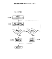
図10〜図12は、導入時及び交換時のダウンロードのフローチャートである。図13は、ノード52#4の増設時のダウンロードのシーケンスチャートである。ステップS2において、図13中の(1L),(1R)に示すように、両系隣接ノードへ版数通知要求を送信する。隣接ノード52#1,52#3は、図13中の(2L),(2R)に示すように、NW設定情報、プログラム及び個別設定情報の版数情報をノード52#4に送信して、ノード52#4は版数情報を受信する。ステップS4において、両系からレスポンス有るか否かを判断する。両系からレスポンスが有れば、ステップS6に進む。両系からレスポンス無ければ、ステップS30に進む。ステップS6において、両系通常運用中であるか否かを判断する。両系運用中であれば、ステップS8に進む。両系運用中で無ければ、ステップS32に進む。
【0042】
ステップS8において、図13中の(2)に示すように、両系のNW設定情報及びプログラムの版数が一致するか否かを判断する。一致しなければ、ステップS2に戻る。一致すれば、ステップS10に進む。ステップS10において、自ノードのNW設定情報の版数と隣接ノードのNW設定情報の版数が一致するか否かを判断する。一致すれば、ステップS12に進む。一致しなければ、ステップS14に進む。ステップS12において、NW設定情報要求フラグをオンにする。
【0043】
ステップS14において、自ノードのプログラムの版数と隣接ノードのプログラムの版数が一致するか否かを判断する。一致すれば、ステップS18に進む。一致しなければ、ステップS16に進む。ステップS16において、プログラム要求フラグをオンにする。ステップS18において、自ノードの個別設定情報の版数と隣接ノードが有する自ノードの個別設定情報の版数が一致するか否かを判断する。一致すれば、ステップS50に進む。一致しなければ、ステップS20に進む。ステップS20において、個別設定情報要求フラグをオンにする。
【0044】
ステップS30において、片系からレスポンスが有ったか否かを判断する。レスポンスが有れば、ステップS32に進む。レスポンスが無ければ、ステップS2に戻る。ステップS32において、片系通常運用中であるか否かを判断する。通常運用中で有れば、ステップS34に進む。通常運用中で無ければ、ステップS2に戻る。ステップS34において、自ノードのNW設定情報の版数と隣接ノードのNW設定情報の版数が一致するか否かを判断する。一致すれば、ステップS38に進む。一致しなければ、ステップS36に進む。ステップS36において、NW設定情報要求フラグをオンにする。
【0045】
ステップS38において、自ノードのプログラムの版数と隣接ノードのプログラムの版数が一致するか否かを判断する。一致すれば、ステップS42に進む。一致しなければ、ステップS40に進む。ステップS40において、プログラム要求フラグをオンにする。ステップS42において、自ノードの個別設定情報の版数と隣接ノードが有する自ノードの個別設定情報の版数が一致するか否かを判断する。一致すれば、ステップS60に進む。一致しなければ、ステップS44に進む。ステップS44において、個別設定情報要求フラグをオンにする。
【0046】
図11中のステップS50において、オンフラグ有るか否かを判断する。オンフラグが有れば、ステップS52に進む。オンフラグが無ければ、ステップS56に進む。ステップS52において、図13中の(4)に示すように、左隣接ノード52#1に対して、ダウンロード要求をする。ステップS54において、ダウンロード待ちに入る。ステップS56において、通常運用となる。ステップS60において、オンフラグ有るか否かを判断する。オンフラグが有れば、ステップS62に進む。オンフラグが無ければ、ステップS66に進む。ステップS62において、有効系隣接ノードへダウンロード要求をする。ステップS64において、ダウンロード待ちに入る。ステップS66において、通常運用となる。
【0047】
隣接ノードはダウンロード要求を受けると、図13中の(5),(5')に示すように、フラグオンのものについて、ダウンロードをする。ノード52#4は、ダウンロードされたものを受信する。ステップS80において、データがOKであるか否かを判断する。データがOKで無ければ、ステップS2に戻る。データがOKならば、データを保存して、ステップS82に進む。ステップS82において、図13中の(6)に示すように、リスタートする。ステップS84において、通常運用なり、起動要因を増設時リスタートとして、運用時間を計時する。
【0048】
(2) 個別設定情報ダウンロード
図14は個別設定情報の転送のフローチャートである。図15は個別設定情報の転送のシーケンスチャートである。図14中のステップS100において、ノード52#4は増設の際に個別設定情報が管理端末50や図示しないRS−232Cインターフェースに接続された端末より入力される。ステップS102において、ノード52#4は、図15中の(20)に示すように、左右の隣接ノード52#1,52#3に個別設定情報転送要求をする。隣接ノード52#1は、個別設定情報転送要求を受けると、図15中の(21)に示すように、応答する。ステップS104において、ノード52#4は両系からレスポンスが有ったか否かを判別する。両系からレスポンスが有れば、ステップS106に進む。両系からレスポンスが無ければ、ステップS108に進む。
【0049】
ステップS106において、図15中の(22)に示すように、隣接ノードに個別設定情報を転送する。隣接ノードは、個別設定情報を受信すると隣接装置の個別設定情報として保存する。そして、図15中の(23)に示すように、ノード52#4に応答する。ステップS108において、ノード52#4は片系からレスポンスが有ったか否かを判別する。片系からレスポンスが有れば、ステップS110に進む。片系からレスポンスが無ければ、ステップS102に戻る。ステップS110において、隣接ノードに個別設定情報を転送する。隣接ノード52#1,52#3は、ノード52#4の個別設定情報を受信すると保存して、ノード52#4に応答する。
【0050】
(3) 交換時
例えば、ノード52#4に障害等が発生し、ノード52#4の交換をしたとする。ノード52#4が交換されると、導入時と同様にスタートされて同様の処理を行う。このとき、交換ノード52#4に個別設定情報が設定されていないときでも、交換ノード52#4は、図10中のステップS18における隣接ノードが有する自ノード52#4の個別設定情報の版数と交換ノード52#4が有する個別設定情報の版数との比較により、版数が異なり、最新の個別設定情報が保存されていると判断される場合には、個別設定情報を隣接ノードよりダウンロードする。
【0051】
(4) 一括ダウンロード
プログラムやNW設定情報のバージョンアップ等により、管理端末50が全てのノード52#i(i=1,2…)に対して、ダウンロード行う。各ノード52#i(i=1,…)は、主信号よりダウンロードされたプログラムやNW設定情報を受信してROMに保存する。管理端末50はダウンロードが終了すると、主信号によりリスタートを指示する。ノード52#i(i=1,…)は、リスタートの指示を受けると、強制リスタートを開始する。そして、起動要因を強制リスタートとし、運用時間の計時を開始する。
【0052】
図16は、自発リスタートへ至るフローチャートである。図17は、自発リスタートへ至るシーケンスチャートであり、ノード52#3が強制リスタート失敗し、ノード52#3の左右の隣接ノード52#2,52#4が強制リスタートに成功したときに、ノード52#3が自発リスタートを行う場合を示している。図17中の(51L),(51R)に示すように、管理端末50からノード52#2,52#4にダウンロードされる。図17中の(52L),(52R)に示すように、ノード52#2,52#4は強制リスタートする。一方、ノード52#3は、図17中の(53)に示すように、ノード52#3は強制リスタートに失敗したとする。隣接ノード52#2,52#4は、図17中の(54L),(54R)に示すように、ノード52#3に版数情報を送信する。ステップS150において、隣接ノード52#1,52#4より版数情報を受信する。図17中の(55)に示すように、以下の版数比較を行う。
【0053】
ステップS152において、両系からレスポンス有るか否かを判別する。両系からレスポンスが有れば、ステップS154に進む。両系からレスポンスがなければ、ステップS170に進む。ステップS154において、両系運用中であるか否かを判定する。両系が共に運用中で有れば、ステップS156に進む。両系が運用中でなければ、ステップS172に進む。ステップS156において、NW設定情報一致しているか否かを判別する。一致していれば、ステップS158に進む。一致していなければ、ステップS180に進む。
【0054】
ステップS158において、自個別ノードの個別設定情報の版数と隣接ノードが有する自ノードの個別設定情報の版数が一致するか否かを判断する。一致すれば、ステップS160に進む。一致しなければ、ステップS180に進む。ステップS160において、自ノードのプログラムの版数と隣接ノードのプログラムの版数が一致するか否かを判断する。一致すれば、ステップS184に進む。一致しなければ、ステップS180に進む。ステップS180において、隣接ノードの起動要因が強制リスタート又は自発リスタートであるかを判断する。いずれでもなければ、ステップS184に進む。いずれかであれば、ステップS182に進む。ステップS182において、隣接ノードの起動時間が自ノードの起動時間よりも新しいか否かを判断する。新しい場合には、ステップS190に進む。
【0055】
ステップS170において、片系からレスポンスが有ったか否かを判断する。レスポンスが有れば、ステップS172に進む。レスポンスが無ければ、ステップS186に進む。ステップS172において、片系通常運用中であるか否かを判断する。通常運用中で有れば、ステップS174に進む。通常運用中で無ければ、ステップS276に進む。ステップS174において、NW設定情報一致しているか否かを判別する。一致していれば、ステップS174に進む。一致していなければ、ステップS180に進む。ステップS176において、自個別ノードの個別設定情報の版数と隣接ノードが有する自ノードの個別設定情報の版数が一致するか否かを判断する。一致すれば、ステップS178に進む。一致しなければ、ステップS180に進む。ステップS178において、自ノードのプログラムの版数と隣接ノードのプログラムの版数が一致するか否かを判断する。一致すれば、ステップS188に進む。一致しなければ、ステップS180に進む。
【0056】
ステップS184,S186において、ノード運用中とする。ステップS190において、版数が異なるものについて、フラグをオンにして、起動時刻が最も新しい隣接ノード52#1に対して、図17中の(56L)に示すように、ダウンロード要求を行い、図17中の(57L)(57'L)に示すように、隣接ノード52#1は、ダウンロード要求フラグオンされたものについて、ノード52#3にダウンロードし、ノード52#3は、正常にダウンロードされると、図17中の(58)に示すように、起動要因を自発リスタートして、通常運用に入る。ノード52#3は、自発リスタートすると、隣接ノード52#4,52#1に、起動要因を自発リスタートとする版数情報を通知する。これにより、強制リスタート失敗した場合に、隣接ノードより、自動的にダウンロードされて、自発リスタートされる。
【0057】
また、ノード52#2,52#3,52#4で強制リスタート失敗し、ノード52#1が強制リスタート成功した場合には、上述したと同様にして、ノード52#1がノード52#2に版数情報を通知する。ノード52#2は、版数情報を受け取ると、上述したようにノード52#1にダウンロード要求を行い、ダウンロードされると自発リスタートをして、通常運用に入る。そして、ノード52#3に起動要因を自発リスタートとする版数情報を通知する。
【0058】
ノード52#3は上述したと同様にしてノード52#2よダウンロード要求を行い、ダウンロードされると自発リスタートして、通常運用に入り、ノード52#4に起動要因を自発リスタートとする版数情報の通知をする。このように、3個以上の直列に接続されたノード52#2,52#3,52#4が強制リスタートに失敗しても、ダウンロードに成功したノードより順次ダウンロードされる。
【0059】
以上説明した実施形態によれば、2台目以降の初期導入時、導入現場での作業としてプログラム版数と整合性の確認や入れ替え、ネットワーク設定情報の設定、装置個別設定情報の設定が不要により、システムエンジニアレベルのネットワーク知識を有する作業員が不要となる。従って、導入装置の台数が多い場合など、装置設定に伴う人件費の大幅な削減となる。
【0060】
また、装置交換時も同様に、運用中のプログラム版数と交換装置版数との整合性の確認や入れ替え、及びネットワーク設定情報の再設定、装置個別設定情報の再設定が不要により、システムエンジニアレベルのネットワーク知識を有する作業員が不要となり、現場に赴くのは工事担当者のみで良く、人件費の削減になる。プログラム一括入れ替えに失敗した場合の自動リカバリでは復旧時間が最小の時間でリカバリができる。また、失敗した箇所が複数ある場合でも、復旧時間はその数に関係なく最小時間で復旧が可能である。
【0061】
本発明は以下の付記を含むものである。
【0062】
(付記1) データを記憶するデータ記憶部と、
前記データの版数情報を管理する版数管理部と、
自装置が立ち上げられた時、隣接ネットワーク装置が有するデータの版数情報の送信を該隣接ネットワーク装置に要求する版数送信要求部と、
前記版数管理部により管理されるデータの版数情報と前記送信要求に基づいて送信された前記隣接ネットワーク装置が有するデータの版数情報とを比較する版数比較部と、
前記版数比較部の比較結果に基づいて、前記隣接ネットワーク装置にデータの送信を要求するデータ送信要求部と、
前記データ送信要求部の要求に基づいて隣接ネットワーク装置から送信されたデータを受信して、該データを前記データ記憶部に記憶するデータ受信部と、
前記データ受信部が受信したデータに基づいて、リスタートするリスタート制御部と、
を具備したことを特徴とするネットワーク装置。
【0063】
(付記2) 隣接ネットワーク装置からの版数情報の送信要求に基づいて、自装置が有するデータの版数情報を該隣接ネットワーク装置に送信する版数情報送信部と、隣接ネットワーク装置からのデータの送信要求に基づいて、自装置が有するデータを送信するデータ送信部とを更に具備したことを特徴とする付記1記載のネットワーク装置。
【0064】
(付記3) 自装置の状態を管理する状態管理部、隣接ネットワーク装置に状態の送信要求する状態送信要求部と、隣接ネットワーク装置からの状態の送信要求に基づいて、前記状態管理部が管理する状態を該隣接ネットワーク装置に送信する状態送信部とを更に具備し、前記データ送信要求部は、該隣接ネットワーク装置が運用状態であり且つデータの版数が異なる場合に該データの送信を要求することを特徴とする付記2記載のネットワーク装置。
【0065】
(付記4) 自装置がネットワークに導入されたとき、自装置に設定された個別設定データを隣接ネットワーク装置に送信する個別設定データ送信部と、第2データ記憶部と、隣接ネットワーク装置から送信された個別設定データを受信して、前記第2データ記憶部に保存する個別設定データ受信部と、隣接ネットワーク装置からの送信要求に基づいて、前記第2データ記憶部に保存された個別設定データを送信する個別設定情報送信部とを更に具備したことを特徴とする付記3記載のネットワーク装置。
【0066】
(付記5) 前記データは、プログラムデータ、ネットワーク装置に共通のネットワーク設定データ及び前記個別設定データであり、前記データ送信要求部はプログラムデータ及びネットワーク設定データについては版数が異なる場合、個別設定データについては自装置の個別設定データが隣接ネットワーク装置に保存されている場合、隣接ネットワーク装置に送信要求をすることを特徴とする付記4記載のネットワーク装置。
【0067】
(付記6) 外部からの強制リスタート要求に基づいてリスタートする第2リスタート制御部と、リスタートされた起動要因及びリスタートしてからの運用時間を管理する起動要因管理部と、リスタートしたとき起動要因及び運用時間を隣接ネットワーク装置に送信する起動要因送信部と、隣接ネットワーク装置から送信された起動要因が強制リスタート要求であり、該隣接ネットワーク装置の運用時間が自装置の運用時間よりも短いときに、該隣接ネットワーク装置にデータの送信を要求する第2データ送信要求部と、隣接ネットワーク装置から送信された第2データ送信要求部の要求に基づくデータを受信して、該データを前記データ記憶部に記憶する第2データ受信部と、該データに基づいて自発リスタートをする第3リスタート制御部とを更に具備したことを特徴とする付記5記載のネットワーク装置。
【0068】
(付記7) 前記起動要因送信部は、前記自発リスタートをしたとき、自発リスタートとする起動要因を隣接ネットワーク装置に送信し、前記第2データ送信要求部は、起動要因が自発リスタートであり、運用時間が自装置の運用時間よりも短いときに、隣接ネットワーク装置にデータの送信を要求することを特徴とする付記6記載のネットワーク装置。
【0069】
(付記8) 前記状態管理部が管理する状態は、隣接ネットワーク装置からのデータの転送待ちであるダウンロード待ち状態、運用状態及び通信不可状態を含むことを特徴とする付記3記載のネットワーク装置。
【0070】
【発明の効果】
以上説明した本発明によれば、導入時に隣接ノードよりデータをダウンロードするので、オペレータが不要となる。
【図面の簡単な説明】
【図1】本発明の原理図である。
【図2】本発明の実施形態によるネットワーク構成図である。
【図3】図2中のノード構成図である。
【図4】図3中のプラグイン制御部の構成図である。
【図5】状態遷移図である。
【図6】版数情報の内容を示す図である。
【図7】導入時のダウンロード、ウェイトの条件を示す図である。
【図8】ダウンロード要求内容を示す図である。
【図9】自発リスタートと版数情報の関係を示す図である。
【図10】導入時及び交換時のダウンロードのフローチャートである。
【図11】導入時及び交換時のダウンロードのフローチャートである。
【図12】導入時及び交換時のダウンロードのフローチャートである。
【図13】導入時のシーケンスチャートである。
【図14】個別設定情報転送のフローチャートである。
【図15】個別設定情報転送のシーケンスチャートである。
【図16】自発リスタートへ至るフローチャートである。
【図17】自発リスタートへ至るシーケンスチャートである。
【符号の説明】
2#1,2#2 ノード
4#2 データ記憶部
6#2 版数管理部
8#2 版数送信要求部
10#2 版数比較部
12#2 データ送信要求部
14#2 データ受信部
16#2 リスタート制御部[0001]
BACKGROUND OF THE INVENTION
The present invention relates to a network device, and more particularly to control of downloading and restarting an exchange, an operating program, and operation data required when operating the network device.
[0002]
[Prior art]
A network such as a corporate network is composed of a plurality of network devices (nodes). The node has a router function that supports a plurality of low-speed LAN interfaces and a high-speed interface that forms a backbone network between nodes, for example, a function of an SDH device that supports an SDH, a SONET interface, and the like. The network is operated by newly introducing a plurality of nodes and connecting the nodes. In the case of a node failure or the like, it is replaced with a new network device. In addition, program and setting information version upgrades are performed simultaneously on all nodes during operation.
[0003]
(1) At the time of introduction
▲ 1 ▼ Router
It is necessary to set network setting information (NW setting information) and individual setting information for the introduction node. The NW setting information is information that nodes must have in common, such as IP address information, node number information, VLAN setting information, and the like. The individual setting information is individual information of each node, for example, LAN interface information accommodated by each port. Conventionally, this is performed by an operator, setting data is stored in the apparatus, and a backup of the setting data is stored on a medium.
[0004]
(2) SDH equipment
It is necessary to install a monitoring program and set individual setting information. The monitoring program is a program that monitors whether the SDH apparatus is operating normally. The individual setting information is individual information for each node, for example, time slot allocation information, QoS setting information, and the like. Conventionally, this is done by downloading from the management terminal on the center side by an operator, collecting individual setting information at the management terminal, and backing up to a medium.
[0005]
(2) When replacing the device
▲ 1 ▼ Router
It is necessary to do the same thing as the introduction. This was done by resetting the setting data backed up on the medium at the time of introduction by the operator.
[0006]
(2) SDH equipment
When the version of the program installed on the exchange node is different from the version of the exchange device, the program operated by the operator is downloaded from the management terminal. In addition, the setting data backed up at the time of introduction is reset by the operator from the management terminal.
[0007]
(3) Batch change
When changing the version of the program or setting data (IP address version) at a time during operation, download the program or setting data from the management terminal to all devices and perform data exchange at the same time. The operator confirms from the management terminal whether the version has been changed.
[0008]
[Problems to be solved by the invention]
However, conventionally, there are the following problems.
[0009]
(1) At the time of introduction
In general, the network setting of the router is complicated, and an operator at the system engineer level is required in addition to the equipment facility construction worker. Therefore, as the number of installed units increases, the operator's work cost also increases in proportion. It is necessary to make sure that the version number of the program or NW setting information operated on the already installed network is the same as the version number of the program installed in the added device. This is because a failure that makes monitoring impossible occurs if the version of the monitoring program is different. In addition, if the version number of the IP address differs depending on the node, such as IPv4 and IPv6, routing becomes impossible. For this reason, the network may be disconnected if it is not compatible or starts up with a different version number.
[0010]
(2) When replacing the device
It is essential to check that the version of the program and setting data being operated are the same or compatible, as in the case of initial node expansion. If they are different, installation work is required and the work is complicated. become. Further, it is necessary to reset backup data by an operator for operation. However, in the case of a router, there is a problem that knowledge about the network is required, and it is usually accompanied by a work of a system engineer level person, so that a worker different from the apparatus installation work person is required and the cost is increased.
[0011]
(3) Batch replacement during operation
At the time of program replacement, in order to shorten the network disconnection due to program switching, switching is performed at the same time by an operator's instruction from the management terminal. At this time, the network may be disconnected if there is any node that has failed to be switched. In this case, the operator must use the management terminal to check whether switching has succeeded for each node, and check the disconnected location, and the network is disconnected until the survey is completed. become. In particular, when nodes are cascade-connected and the management terminal is connected to one terminal node, when the network is cut off due to unsuccessful switching of the other terminal node, it takes time to complete the investigation. . In addition, when there are a plurality of network disconnection points, recovery is performed one by one, so that it takes time to recover in proportion to the disconnection points.
[0012]
The present invention has been made in view of the above, and an object of the present invention is to provide a network device that can automatically match the operation data version numbers when performing introduction, replacement, and batch replacement during operation.
[0013]
[Means for Solving the Problems]
FIG. 1 is a principle diagram of the present invention. As shown in FIG. 1,
[0014]
The version number
[0015]
DETAILED DESCRIPTION OF THE INVENTION
FIG. 2 is a network configuration diagram according to an embodiment of the present invention. 2A is a diagram showing a ring-connected network, and FIG. 2B is a diagram showing a cascade-connected network. As shown in FIGS. 2A and 2B, the network includes a
[0016]
The
[0017]
FIG. 3 is a configuration diagram of the
[0018]
FIG. 4 is a configuration diagram of the plug-in
[0019]
The
[0020]
FIG. 5 is a diagram illustrating state transition. The start / restart is a node when the reset button is turned on or the power is turned on, when the program, NW setting information and individual setting information are downloaded, or when the restart is instructed from the outside by the
[0021]
The operating condition abnormality means a state in which an abnormality has been detected by operating condition confirmation. Download waiting means that a program or the like is waiting to be downloaded from an adjacent node. Downloading means that a program or the like is being downloaded. Download completion means that the program has been downloaded. “Loading FPGA” means a state in which data is being loaded into the FPGA. In the FPGA, a part of the SDH apparatus is constituted by the FPGA, and the function of the SDH apparatus is determined by loading the FPGA data which is the individual setting data. The FPGA abnormality means a state in which an abnormality of the FPGA data has occurred. Normal operation means that the node is in operation. The above state transitions as shown in FIG.
[0022]
The adjacent node
[0023]
The activation
[0024]
The main
[0025]
[0026]
(1) The following processing is performed at the time of introduction.
[0027]
(i) Request version number information from the adjacent node through the
[0028]
FIG. 7A to FIG. 7C are diagrams showing download and wait conditions at the time of introduction. 7A shows a case where the version number of the own node is V0, FIG. 7B shows a case where the version number of the own node is V1, and FIG. It is a figure which shows the case where the version number is V2. Here, the version number refers to the program version number or the version number of the NW setting information. DL means download. The download target at the time of introduction is a program of the version to be compared or NW setting information. WAIT means a state waiting for download. Activation is a condition for restarting without downloading.
[0029]
The restart is started when the version number of the program and the version number of the NW setting information satisfy the conditions shown in the figure. In the figure, the left view shows the state of the left adjacent node, and the upper view shows the state of the right adjacent node. In the figure, the left view is extended to the right and the upper column is extended to the lower side to indicate the state in which the own node transitions. For example, if the left and right adjacent nodes are in operation and the version numbers are both V1, they are downloaded (DL). The download is performed from the left adjacent node, for example. If both the left and right adjacent nodes are in operation, but the version numbers are different, for example, if the version number of the left adjacent node is V1 and the version number of the right adjacent node is V2, wait. This is because the nodes in operation should have the same version number, so that different version numbers are not in a normal state, and thus wait until a normal state is reached.
[0030]
(v) When it is necessary to download, the corresponding version number is requested to download to the adjacent node through the
[0031]
(2) At the time of node replacement, the same processing as at the time of introduction is performed. At this time, if the latest individual setting information is not set in the exchange node, the individual setting information stored in the adjacent node at the time of introduction is downloaded. The individual setting information is downloaded because the version number of the individual setting information stored in the adjacent node is different from the version number of the individual setting information stored in the own apparatus individual setting
[0032]
(3) The following processing relating to an external restart instruction is performed.
[0033]
(i) When the
[0034]
(iii) If the download condition is satisfied, after downloading, the
[0035]
(4) When version number information is requested from the adjacent node, the version number information shown in FIG. 6 is acquired from the version
[0036]
(5) When a download is requested from an adjacent node, the corresponding
[0037]
(6) When the individual setting information is transferred from the adjacent node, it is stored in the adjacent device individual setting
[0038]
The
[0039]
The operation of FIG. 2 will be described below.
[0040]
(1) At the time of introduction
The operation at the time of introduction will be described by taking as an example a case where a
[0041]
10 to 12 are flowcharts of downloading at the time of introduction and replacement. FIG. 13 is a download sequence chart when the
[0042]
In step S8, as shown in (2) in FIG. 13, it is determined whether or not the NW setting information and the program version number of both systems match. If they do not match, the process returns to step S2. If they match, the process proceeds to step S10. In step S10, it is determined whether or not the version number of the NW setting information of the own node matches the version number of the NW setting information of the adjacent node. If they match, the process proceeds to step S12. If not, the process proceeds to step S14. In step S12, the NW setting information request flag is turned on.
[0043]
In step S14, it is determined whether or not the version number of the program of the own node matches the version number of the program of the adjacent node. If they match, the process proceeds to step S18. If not, the process proceeds to step S16. In step S16, the program request flag is turned on. In step S18, it is determined whether or not the version number of the individual node individual setting information matches the version number of the own node individual setting information of the adjacent node. If they match, the process proceeds to step S50. If not, the process proceeds to step S20. In step S20, the individual setting information request flag is turned on.
[0044]
In step S30, it is determined whether or not there is a response from one system. If there is a response, the process proceeds to step S32. If there is no response, the process returns to step S2. In step S32, it is determined whether or not one-system normal operation is being performed. If it is under normal operation, the process proceeds to step S34. If not in normal operation, the process returns to step S2. In step S34, it is determined whether the version number of the NW setting information of the own node matches the version number of the NW setting information of the adjacent node. If they match, the process proceeds to step S38. If not, the process proceeds to step S36. In step S36, the NW setting information request flag is turned on.
[0045]
In step S38, it is determined whether or not the version number of the program of the own node matches the version number of the program of the adjacent node. If they match, the process proceeds to step S42. If not, the process proceeds to step S40. In step S40, the program request flag is turned on. In step S42, it is determined whether or not the version number of the individual setting information of the own node matches the version number of the individual setting information of the own node of the adjacent node. If they match, the process proceeds to step S60. If not, the process proceeds to step S44. In step S44, the individual setting information request flag is turned on.
[0046]
In step S50 in FIG. 11, it is determined whether there is an on flag. If there is an ON flag, the process proceeds to step S52. If there is no ON flag, the process proceeds to step S56. In step S52, a download request is made to the left
[0047]
When the adjacent node receives the download request, as shown in (5) and (5 ′) in FIG.
[0048]
(2) Individual setting information download
FIG. 14 is a flowchart of transfer of individual setting information. FIG. 15 is a sequence chart of transfer of individual setting information. In step S100 in FIG. 14, when the
[0049]
In step S106, the individual setting information is transferred to the adjacent node as indicated by (22) in FIG. When the adjacent node receives the individual setting information, the adjacent node stores it as the individual setting information of the adjacent device. Then, as indicated by (23) in FIG. 15, it responds to the
[0050]
(3) When replacing
For example, assume that a failure or the like occurs in the
[0051]
(4) Batch download
The
[0052]
FIG. 16 is a flowchart up to the spontaneous restart. FIG. 17 is a sequence chart leading to a spontaneous restart when the
[0053]
In step S152, it is determined whether or not there is a response from both systems. If there is a response from both systems, the process proceeds to step S154. If there is no response from both systems, the process proceeds to step S170. In step S154, it is determined whether or not both systems are operating. If both systems are in operation, the process proceeds to step S156. If both systems are not in operation, the process proceeds to step S172. In step S156, it is determined whether the NW setting information matches. If they match, the process proceeds to step S158. If not, the process proceeds to step S180.
[0054]
In step S158, it is determined whether or not the version number of the individual setting information of the own individual node matches the version number of the individual setting information of the own node of the adjacent node. If they match, the process proceeds to step S160. If not, the process proceeds to step S180. In step S160, it is determined whether or not the version number of the program of the own node matches the version number of the program of the adjacent node. If they match, the process proceeds to step S184. If not, the process proceeds to step S180. In step S180, it is determined whether the activation factor of the adjacent node is a forced restart or a spontaneous restart. Otherwise, the process proceeds to step S184. If it is either, the process proceeds to step S182. In step S182, it is determined whether the activation time of the adjacent node is newer than the activation time of the own node. If it is new, the process proceeds to step S190.
[0055]
In step S170, it is determined whether or not there is a response from one system. If there is a response, the process proceeds to step S172. If there is no response, the process proceeds to step S186. In step S172, it is determined whether one-system normal operation is being performed. If it is under normal operation, the process proceeds to step S174. If it is not under normal operation, the process proceeds to step S276. In step S174, it is determined whether the NW setting information matches. If they match, the process proceeds to step S174. If not, the process proceeds to step S180. In step S176, it is determined whether or not the version number of the individual setting information of the own individual node matches the version number of the individual setting information of the own node of the adjacent node. If they match, the process proceeds to step S178. If not, the process proceeds to step S180. In step S178, it is determined whether or not the version number of the program of the own node matches the version number of the program of the adjacent node. If they match, the process proceeds to step S188. If not, the process proceeds to step S180.
[0056]
In steps S184 and S186, the node is in operation. In step S190, for the different version numbers, the flag is turned on and a download request is made to the
[0057]
Further, when the forced restart fails at the
[0058]
The
[0059]
According to the embodiment described above, at the time of initial installation of the second and subsequent units, it is unnecessary to check and replace the program version number and consistency, to set network setting information, and to set device individual setting information as work at the installation site This eliminates the need for workers having network knowledge at the system engineer level. Therefore, when the number of introduced devices is large, the labor cost associated with device setting is greatly reduced.
[0060]
Similarly, when a device is replaced, the system engineer does not need to check and replace the consistency between the operating program version and the replacement device version, reset the network setting information, and reset the device individual setting information. Workers with a high level of network knowledge are not required, and only the construction personnel need to go to the site, which reduces labor costs. With automatic recovery when program batch replacement fails, recovery can be performed in a minimum recovery time. Further, even when there are a plurality of failed locations, the recovery time can be recovered with the minimum time regardless of the number.
[0061]
The present invention includes the following supplementary notes.
[0062]
(Supplementary note 1) a data storage unit for storing data;
A version number management unit for managing version number information of the data;
A version number transmission requesting unit that requests the neighboring network device to transmit the version number information of the data that the neighboring network device has when the own device is started;
A version number comparison unit that compares the version number information of the data managed by the version number management unit with the version number information of the data that the adjacent network device has transmitted based on the transmission request;
Based on the comparison result of the version number comparison unit, a data transmission request unit that requests the adjacent network device to transmit data;
A data reception unit that receives data transmitted from an adjacent network device based on a request from the data transmission request unit, and stores the data in the data storage unit;
A restart control unit that restarts based on the data received by the data receiving unit;
A network apparatus comprising:
[0063]
(Supplementary note 2) Based on a version number information transmission request from an adjacent network device, a version number information transmission unit for transmitting the version number information of the data of the own device to the adjacent network device, and the data of the data from the adjacent network device The network device according to
[0064]
(Additional remark 3) Based on the state management part which manages the state of a self-apparatus, the state transmission request part which requests | requires state transmission to an adjacent network apparatus, and the state transmission request from an adjacent network apparatus, the said state management part manages A status transmission unit that transmits the status to the adjacent network device, and the data transmission request unit requests transmission of the data when the adjacent network device is in an operating state and the data version number is different. The network device according to
[0065]
(Supplementary Note 4) When the own device is introduced into the network, the individual setting data transmitting unit that transmits the individual setting data set in the own device to the adjacent network device, the second data storage unit, and the adjacent network device are transmitted. Receiving the individual setting data and storing the individual setting data stored in the second data storage unit and the individual setting data stored in the second data storage unit based on the transmission request from the adjacent network device. The network device according to
[0066]
(Supplementary Note 5) The data is program data, network setting data common to a network device and the individual setting data, and the data transmission request unit has individual setting data when the version numbers of the program data and the network setting data are different. The network device according to
[0067]
(Appendix 6) A second restart control unit that restarts based on a forced restart request from the outside, an activation factor management unit that manages the restarted activation factor and the operation time after the restart, An activation factor transmission unit that transmits an activation factor and operation time to an adjacent network device when started, and an activation factor transmitted from the adjacent network device is a forced restart request, and the operation time of the adjacent network device is the operation of the own device When the time is shorter than the time, the second data transmission request unit that requests the adjacent network device to transmit data, and the data based on the request of the second data transmission request unit transmitted from the adjacent network device, A second data receiving unit for storing data in the data storage unit, and a third restart control unit for performing a spontaneous restart based on the data The network device according to appendix 5, further comprising:
[0068]
(Supplementary Note 7) When the activation factor transmission unit performs the spontaneous restart, the activation factor transmission unit transmits an activation factor to be a spontaneous restart to the adjacent network device, and the second data transmission request unit has an activation factor of the spontaneous restart. The network device according to
[0069]
(Supplementary note 8) The network device according to
[0070]
【The invention's effect】
According to the present invention described above, since data is downloaded from the adjacent node at the time of introduction, an operator becomes unnecessary.
[Brief description of the drawings]
FIG. 1 is a principle diagram of the present invention.
FIG. 2 is a network configuration diagram according to an embodiment of the present invention.
FIG. 3 is a node configuration diagram in FIG. 2;
4 is a configuration diagram of a plug-in control unit in FIG. 3. FIG.
FIG. 5 is a state transition diagram.
FIG. 6 is a diagram showing the contents of version number information.
FIG. 7 is a diagram showing download and wait conditions at the time of introduction.
FIG. 8 is a diagram showing download request contents.
FIG. 9 is a diagram illustrating a relationship between spontaneous restart and version number information.
FIG. 10 is a flowchart of download at the time of introduction and replacement.
FIG. 11 is a flowchart of download at the time of introduction and replacement.
FIG. 12 is a flowchart of download at the time of introduction and replacement.
FIG. 13 is a sequence chart at the time of introduction.
FIG. 14 is a flowchart of individual setting information transfer.
FIG. 15 is a sequence chart of individual setting information transfer.
FIG. 16 is a flowchart up to a spontaneous restart.
FIG. 17 is a sequence chart leading to a spontaneous restart.
[Explanation of symbols]
2 # 1, 2 # 2 nodes
4 # 2 data storage
6 # 2 Version Management Department
8 # 2 Version number transmission request part
10 # 2 version comparison section
12 # 2 Data transmission request part
14 # 2 data receiver
16 # 2 Restart control unit
Claims (6)
前記データの版数情報を管理する版数管理部と、
自装置の状態を管理する状態管理部と、
自装置が立ち上げられた時、隣接ネットワーク装置が有するデータの版数情報及び該隣接ネットワークの状態に関する情報の送信を該隣接ネットワーク装置に要求する版数送信要求部と、
前記版数管理部により管理されるデータの版数情報と前記送信要求に基づいて送信された前記隣接ネットワーク装置が有するデータの版数情報とを比較する版数比較部と、
前記版数比較部による比較の結果、版数が不一致であり、かつ、前記送信要求に基づいて送信された前記隣接ネットワーク装置の状態に関する情報が正常運用であることを示している場合に、前記隣接ネットワーク装置にデータの送信を要求するデータ送信要求部と、
前記データ送信要求部の要求に基づいて隣接ネットワーク装置から送信されたデータを受信して、該データを前記データ記憶部に記憶するデータ受信部と、
前記データ受信部が受信したデータに基づいて、リスタートするリスタート制御部と、
を具備したことを特徴とするネットワーク装置。A data storage unit for storing data;
A version number management unit for managing version number information of the data;
A state management unit for managing the state of the own device;
A version number transmission requesting unit for requesting the neighboring network device to transmit information about the version number of data held by the neighboring network device and information on the state of the neighboring network when the own device is started;
A version number comparison unit that compares the version number information of the data managed by the version number management unit with the version number information of the data that the adjacent network device has transmitted based on the transmission request;
As a result of the comparison by the version number comparison unit , when the version numbers are inconsistent and the information regarding the state of the adjacent network device transmitted based on the transmission request indicates normal operation, A data transmission request unit that requests transmission of data to an adjacent network device;
A data reception unit that receives data transmitted from an adjacent network device based on a request from the data transmission request unit, and stores the data in the data storage unit;
A restart control unit that restarts based on the data received by the data receiving unit;
A network apparatus comprising:
前記隣接ネットワーク装置の前記データ送信要求部からの要求に基づいて、自装置が有するデータを送信するデータ送信部とを更に具備した請求項1記載のネットワーク装置。 Based on a request from the version number transmission request unit of the adjacent network device, a version number information transmission unit that transmits the version number information of the data of the own device and information on the state of the own device to the adjacent network device;
The network device according to claim 1, further comprising a data transmission unit that transmits data included in the own device based on a request from the data transmission request unit of the adjacent network device .
前記隣接ネットワーク装置から送信された個別設定データを受信して、前記第2データ記憶部に保存する個別設定データ受信部と、
前記隣接ネットワーク装置からの送信要求に基づいて、前記第2データ記憶部に保存された個別設定データを送信する個別設定情報送信部とを備え、
前記版数情報は、個別設定データに関する版数情報を含み、前記データ送信要求部は、前記第2データ記憶部に格納している前記自装置に関する個別設定データの版数と、前記個別設定データ受信部が受信した前記隣接ネットワーク装置が保持していた前記自装置に関する個別設定データの版数とが不一致であり、かつ、前記送信要求に基づいて送信された前記隣接ネットワーク装置の状態に関する情報が正常運用であることを示している場合に、前記隣接ネットワーク装置に前記個別設定データの送信を要求することを特徴とする請求項1記載のネットワーク装置。 A second data storage unit for storing individual setting data relating to the own device and individual setting data relating to an adjacent network device of the own device;
Receiving personalization data transmitted from the neighboring network devices, and the individual setting data receiving unit to be stored in the second data storage unit,
On the basis of the transmission request from the neighbor network device, and a separate setting information transmitting unit for transmitting personalization data stored in the second data storage unit,
The version number information includes version number information related to individual setting data, and the data transmission request unit includes a version number of the individual setting data stored in the second data storage unit and the individual setting data. Information about the state of the adjacent network device transmitted based on the transmission request is inconsistent with the version number of the individual setting data related to the own device held by the adjacent network device received by the receiving unit. when the identification information indicates that the normal operation, the network device according to claim 1, wherein the requesting the transmission of the individual setting data to the neighboring network device.
前記データ送信要求部は前記プログラムデータ及び前記ネットワーク設定データについて版数が異なる場合に前記隣接ネットワーク装置に送信要求をすることを特徴とする請求項1記載のネットワーク装置。 The data includes program data, network setting data common to network devices,
2. The network device according to claim 1, wherein the data transmission request unit requests the adjacent network device to transmit when the program data and the network setting data have different version numbers .
Priority Applications (1)
| Application Number | Priority Date | Filing Date | Title |
|---|---|---|---|
| JP2001283341A JP4098504B2 (en) | 2001-09-18 | 2001-09-18 | Network equipment |
Applications Claiming Priority (1)
| Application Number | Priority Date | Filing Date | Title |
|---|---|---|---|
| JP2001283341A JP4098504B2 (en) | 2001-09-18 | 2001-09-18 | Network equipment |
Publications (2)
| Publication Number | Publication Date |
|---|---|
| JP2003092602A JP2003092602A (en) | 2003-03-28 |
| JP4098504B2 true JP4098504B2 (en) | 2008-06-11 |
Family
ID=19106843
Family Applications (1)
| Application Number | Title | Priority Date | Filing Date |
|---|---|---|---|
| JP2001283341A Expired - Fee Related JP4098504B2 (en) | 2001-09-18 | 2001-09-18 | Network equipment |
Country Status (1)
| Country | Link |
|---|---|
| JP (1) | JP4098504B2 (en) |
Families Citing this family (8)
| Publication number | Priority date | Publication date | Assignee | Title |
|---|---|---|---|---|
| JP4576130B2 (en) * | 2004-02-12 | 2010-11-04 | パイオニア株式会社 | Version updating method for communication system application program and program therefor |
| JP4831943B2 (en) * | 2004-07-30 | 2011-12-07 | 三洋電機株式会社 | Digital broadcast receiver |
| JP4375197B2 (en) | 2004-10-25 | 2009-12-02 | 日本電気株式会社 | Wireless LAN system, wireless terminal, wireless base station, wireless terminal communication setting method and program thereof |
| WO2006075368A1 (en) * | 2005-01-13 | 2006-07-20 | Fujitsu Limited | Communication system, communication apparatus and communication method |
| JP5440009B2 (en) * | 2009-07-31 | 2014-03-12 | 富士通株式会社 | Program update method for multi-cluster system and multi-cluster system |
| EP3373135A4 (en) * | 2015-11-02 | 2019-05-22 | Ricoh Company, Ltd. | Information processing device, communication system, and information processing method |
| JP6658157B2 (en) * | 2016-03-17 | 2020-03-04 | 株式会社リコー | Information processing apparatus, system, program, and processing method |
| CN114297125B (en) * | 2021-12-30 | 2024-02-09 | 山东云海国创云计算装备产业创新中心有限公司 | Server, I2C network and control strategy updating method thereof |
-
2001
- 2001-09-18 JP JP2001283341A patent/JP4098504B2/en not_active Expired - Fee Related
Also Published As
| Publication number | Publication date |
|---|---|
| JP2003092602A (en) | 2003-03-28 |
Similar Documents
| Publication | Publication Date | Title |
|---|---|---|
| US7139839B2 (en) | Method and apparatus for assigning a network node address | |
| CN102771092B (en) | Communications device and address learning method | |
| JP4484803B2 (en) | Network operation management system | |
| CN1290089A (en) | Automatic telecommunication link identifying system | |
| JP4098504B2 (en) | Network equipment | |
| JP3837696B2 (en) | Transmission apparatus and data transmission method | |
| JP4567233B2 (en) | COMMUNICATION DEVICE AND ITS CONTROL METHOD | |
| CN104125079A (en) | Method and device for determining double-device hot-backup configuration information | |
| CN118394388B (en) | Firmware upgrade method, device, storage medium, electronic device and computer program product | |
| KR19990036307A (en) | Additional Route Determination Methods and Nodes Used in Node Networks | |
| GB2362230A (en) | Delegated fault detection in a network by mutual node status checking | |
| US5796933A (en) | Back-up method for equipment settings | |
| CN113824595B (en) | Link switching control method and device and gateway equipment | |
| KR102286913B1 (en) | Network management apparatus and control method thereof | |
| JP2010016597A (en) | Node, and network system | |
| CN112532454A (en) | FC switching network system network management method | |
| JP4127747B2 (en) | Network system, network system initialization method, and node device | |
| JP3246409B2 (en) | Fault monitoring method | |
| JP7478277B1 (en) | SIM, communication device, switching method, and program | |
| CN111953562B (en) | Equipment state monitoring method and device | |
| JP2005229146A (en) | Communication control device | |
| JPH09198103A (en) | Device status notification method | |
| JP3541337B2 (en) | Network management system and network configuration information management method | |
| US11876555B2 (en) | Failure determination system and failure determination method | |
| CN108966258A (en) | System and method for correcting the network connectivity of connection equipment |
Legal Events
| Date | Code | Title | Description |
|---|---|---|---|
| A621 | Written request for application examination |
Free format text: JAPANESE INTERMEDIATE CODE: A621 Effective date: 20060222 |
|
| A977 | Report on retrieval |
Free format text: JAPANESE INTERMEDIATE CODE: A971007 Effective date: 20071025 |
|
| A131 | Notification of reasons for refusal |
Free format text: JAPANESE INTERMEDIATE CODE: A131 Effective date: 20071106 |
|
| A521 | Written amendment |
Free format text: JAPANESE INTERMEDIATE CODE: A523 Effective date: 20071227 |
|
| TRDD | Decision of grant or rejection written | ||
| A01 | Written decision to grant a patent or to grant a registration (utility model) |
Free format text: JAPANESE INTERMEDIATE CODE: A01 Effective date: 20080311 |
|
| A61 | First payment of annual fees (during grant procedure) |
Free format text: JAPANESE INTERMEDIATE CODE: A61 Effective date: 20080313 |
|
| R150 | Certificate of patent or registration of utility model |
Free format text: JAPANESE INTERMEDIATE CODE: R150 |
|
| FPAY | Renewal fee payment (event date is renewal date of database) |
Free format text: PAYMENT UNTIL: 20110321 Year of fee payment: 3 |
|
| FPAY | Renewal fee payment (event date is renewal date of database) |
Free format text: PAYMENT UNTIL: 20110321 Year of fee payment: 3 |
|
| FPAY | Renewal fee payment (event date is renewal date of database) |
Free format text: PAYMENT UNTIL: 20120321 Year of fee payment: 4 |
|
| LAPS | Cancellation because of no payment of annual fees |