JP4090952B2 - Fuel gas purge system with fault diagnosis function in internal combustion engine - Google Patents
Fuel gas purge system with fault diagnosis function in internal combustion engine Download PDFInfo
- Publication number
- JP4090952B2 JP4090952B2 JP2003185132A JP2003185132A JP4090952B2 JP 4090952 B2 JP4090952 B2 JP 4090952B2 JP 2003185132 A JP2003185132 A JP 2003185132A JP 2003185132 A JP2003185132 A JP 2003185132A JP 4090952 B2 JP4090952 B2 JP 4090952B2
- Authority
- JP
- Japan
- Prior art keywords
- fuel
- purge
- determination condition
- abnormality determination
- integrated
- Prior art date
- Legal status (The legal status is an assumption and is not a legal conclusion. Google has not performed a legal analysis and makes no representation as to the accuracy of the status listed.)
- Expired - Fee Related
Links
Images


Classifications
-
- F—MECHANICAL ENGINEERING; LIGHTING; HEATING; WEAPONS; BLASTING
- F02—COMBUSTION ENGINES; HOT-GAS OR COMBUSTION-PRODUCT ENGINE PLANTS
- F02M—SUPPLYING COMBUSTION ENGINES IN GENERAL WITH COMBUSTIBLE MIXTURES OR CONSTITUENTS THEREOF
- F02M25/00—Engine-pertinent apparatus for adding non-fuel substances or small quantities of secondary fuel to combustion-air, main fuel or fuel-air mixture
- F02M25/08—Engine-pertinent apparatus for adding non-fuel substances or small quantities of secondary fuel to combustion-air, main fuel or fuel-air mixture adding fuel vapours drawn from engine fuel reservoir
- F02M25/0809—Judging failure of purge control system
-
- F—MECHANICAL ENGINEERING; LIGHTING; HEATING; WEAPONS; BLASTING
- F02—COMBUSTION ENGINES; HOT-GAS OR COMBUSTION-PRODUCT ENGINE PLANTS
- F02M—SUPPLYING COMBUSTION ENGINES IN GENERAL WITH COMBUSTIBLE MIXTURES OR CONSTITUENTS THEREOF
- F02M25/00—Engine-pertinent apparatus for adding non-fuel substances or small quantities of secondary fuel to combustion-air, main fuel or fuel-air mixture
- F02M25/08—Engine-pertinent apparatus for adding non-fuel substances or small quantities of secondary fuel to combustion-air, main fuel or fuel-air mixture adding fuel vapours drawn from engine fuel reservoir
- F02M2025/0845—Electromagnetic valves
Landscapes
- Engineering & Computer Science (AREA)
- Chemical & Material Sciences (AREA)
- Combustion & Propulsion (AREA)
- Mechanical Engineering (AREA)
- General Engineering & Computer Science (AREA)
- Supplying Secondary Fuel Or The Like To Fuel, Air Or Fuel-Air Mixtures (AREA)
Description
【0001】
【発明の属する技術分野】
この発明は、キャニスタ内に吸着されている燃料蒸発ガスを内燃機関の吸気管へパージ(放出)する燃料ガスパージシステムの故障の有無を診断するものに関する。
【0002】
【従来の技術】
従来の燃料ガスパージシステムの故障診断装置としては、故障診断条件に機関始動後のパージ実行積算時間または積算パージ量が所定値以上になった時との条件を追加している。この条件で、キャニスタのパージが十分に行われているか否かを判断し、キャニスタ内の燃料蒸発ガスの残留量が十分に少なくなっているときに故障診断を実行する。これにより、故障診断時の吸気管内への燃料蒸発ガスの流入によるオーバーリッチが発生しなくなり、ドライバビリティやエミッションの悪化が防止されるようにしている(例えば、特許文献1)。また、同種の従来の燃料ガスパージシステムの故障診断装置としては、例えば、特許文献2がある。
【0003】
【特許文献1】
特開平9―177617号公報
【特許文献2】
特開平11―22564号公報
【0004】
【発明が解決しようとする課題】
従来の燃料ガスパージシステムの故障診断装置では、異常検出が中断され、再度異常検出を行う場合でも、キャニスタのパージ積算時間を同時間実施するので、異常検出頻度を上げられない問題があった。
【0005】
この発明は、上記のような問題点を解消するためになされたもので、異常検出が中断された場合は、キャニスタのパージを必要とするより短い時間実行してから、再異常検出するようにして、異常検出頻度を上げると共にドライバビリティやエミッションの悪化を防止するものを得ようとするものである。
また、燃料を給油したと判定したときは、燃料の給油による燃料蒸発ガスの流入によるオーバーリッチの発生を防止し、ドライバビリティやエミッションの悪化を防止するものを得ようとするものである。
さらに、パージ制御弁によるパージが導入されていない期間が所定時間以上継続したとき、積算パージ量をクリアして、多くの燃料蒸発ガスの流入によるオーバーリッチの発生を防止し、ドライバビリティやエミッションの悪化を防止するものを得ようとするものである。
【0006】
【課題を解決するための手段】
この発明に係わる内燃機関における故障診断機能を有する燃料ガスパージシステムは、燃料タンクと吸気管とを連通するパージ通路の途中に設けたキャニスタの吸着体で燃料タンク内で発生した燃料ガスを吸着し、内燃機関の運転状態に応じてパージ制御弁を開閉することにより、吸着された燃料ガスを吸気管内に導入して燃料の蒸散を防止する燃料蒸散防止装置と、上記内燃機関の運転状態を検出する複数のセンサと、上記複数のセンサからの運転状態情報に基づいて上記燃料蒸散防止装置の第1異常判定条件の成立を検出する第1異常判定条件検出手段と、上記キャニスタに設けられた大気口を閉塞する大気口閉塞弁と、上記パージ制御弁及び上記大気口閉塞弁を共に閉じて上記燃料蒸散防止装置全体を一つの密閉区間とする密閉化手段と、上記パージ制御弁を開制御している積算時間または上記開制御に基づくパージ積算流量により積算パージ量を計測する積算パージ計測手段と、上記第1異常判定条件が成立し、機関始動後の積算パージ量が第1の所定値以上のときに第2異常判定条件成立とする第2異常判定条件検出手段と、上記燃料タンク内圧力を検出する燃料タンク内圧力センサと、並びに、上記燃料タンク内圧力センサの検出結果に基づいて上記燃料蒸散防止装置の異常を検出する異常検出手段とを備えている。
【0007】
そして上記第2異常判定条件成立後に異常検出を中断した時に、上記積算パージ量をクリアすると共に、次の上記第2異常判定条件の成立には上記積算パージ量が上記第1の所定値より短い第2の所定値以上のときに異常判定条件成立とするようにしたものである。
【0008】
また、燃料給油判定手段で燃料を給油したと判定したときは、上記第2異常判定条件の成立には上記積算パージ量が上記第1の所定値より長い第3の所定値以上のときに異常判定条件成立とするようにしたものである。
【0009】
さらにまた、上記燃料給油判定手段は、車両の速度を検出する車速センサと、上記燃料タンク内に残っている燃料残量を検出する燃料レベルゲージと、タイマとを含んで、燃料の給油を判定するようにしたものである。
【0010】
【発明の実施の形態】
実施の形態1.
図1はこの発明の実施の形態1による故障診断機能を有する燃料ガスパージシステムを示す構成図である。図1において、空気を濾過するエアクリーナ1を介して吸入された空気は、エアクリーナ1に接続されたエアフローセンサ2により吸入空気量Qaが測定され、スロットルバルブ3で吸気量が負荷に応じて制御され、サージタンク4及び吸気管5を介してエンジン6の各気筒に吸入される。エアフローセンサ2は、吸気管5を通過してエンジン6に供給される吸入空気量を測定し、電子制御ユニット(以下、「ECU」という)20に入力する。スロットルバルブ3は、運転者によるアクセルペダルの操作量に応じて、エンジン6への吸気量を調節する。
【0011】
また、吸気管5には各気筒毎にインジェクタ7が設けられており、インジェクタ7は、燃料タンク8内の燃料を吸気管5内に噴射する。また、吸気管5には、各種のセンサと関連した燃料蒸散防止装置を介して、燃料タンク8が連通されている。複数のセンサには、エンジン6の運転状態(エンジン回転速度:回転数Ne、および、負荷状態:充填効率Ecなど)を検出するために、エアフローセンサ2、スロットル開度センサ12、吸気温度センサ13、水温センサ14、空燃比センサ(O2センサ)16、クランク角センサ17、吸気管圧力センサ18、燃料タンク内圧力センサ19、燃料レベルゲージ(燃料レベル検出器)27、車速センサ29、大気圧センサ30、外気温度センサ31および燃料タンク内温度センサ32を含んでいる。
【0012】
スロットル開度センサ12は、スロットルバルブ3の回転軸に設けられて、スロットル開度を検出する。吸気温度センサ13は、吸気管5に設けられて、吸気温度TAを検出する。水温センサ14は、エンジン6の冷却水温度を検出する。空燃比センサ16は、エンジン6の排気管15に設けられて、空燃比フィードバック信号を生成する。クランク角センサ17は、エンジン6の回転速度(回転数Ne)に対応したクランク角信号を生成する。吸気管圧力センサ18は、吸気管5のサージタンク4に設けられて、吸気管5内の吸気管圧力Pbを検出する。燃料タンク内圧力センサ19は、燃料タンク8に設けられて、燃料タンク内圧力Ptを検出する。燃料レベルゲージ27は、燃料タンク8内の燃料レベルLtを検出する。
【0013】
車速センサ29は、エンジン6を搭載した車両28の車軸付近に設けられて、車速を検出する。大気圧センサ30は、外気の圧力を大気圧PAとして検出する。外気温度センサ31は、外気温度TGを検出する。燃料タンク内温度センサ32は、燃料タンク8内の燃料ガス温度TTを検出する。上記複数のセンサの各検出情報は、運転状態を示す情報としてECU20に入力される。
【0014】
燃料蒸散防止装置は、パージ通路に設けられたキャニスタ9と、キャニスタ9と吸気管5との途中に設けられたパージ制御弁10と、パージ制御弁10を開閉制御して燃料の蒸散を防止する燃料蒸散防止制御手段(ECU20に含まれる)とにより構成される。パージ通路は、燃料タンク8と吸気管5との間を連通する。キャニスタ9は、吸着体としての活性炭を内蔵しており、パージ通路の途中に設けられて、燃料タンク8内で発生した燃料ガスを吸着する。キャニスタ9には大気口11が設けられており、大気口11は、大気口制御弁26を介して大気側に開放されている。大気口制御弁26は、ECU20と関連して大気口閉塞手段を構成しており、ECU20の制御下で大気口11を開閉制御する。
【0015】
また、ECU20内の燃料蒸散防止制御手段は、エンジン6の運転状態に応じてパージ制御弁10を開閉制御し、キャニスタ9に吸着された燃料ガスを吸気管5内に適宜導入して燃料の蒸散を防止する。すなわち、燃料蒸散防止制御手段は、エンジン6の運転状態に応じて定まるパージ弁制御量(パージ量に対応したデューティ制御量)によりパージ制御弁10を開弁し、キャニスタ9に吸着された燃料ガスを、吸気管5内の負圧により吸気管5内にパージさせる。このとき、大気口制御弁26および大気口11を介してキャニスタ9に導入された空気は、キャニスタ9内の活性炭を通過する際に、活性炭から脱離された燃料ガスを含んだ空気(パージエア)として、吸気管5内にパージされる。
【0016】
ECU20は、CPU21、ROM22およびRAM23などを有するマイクロコンピュータにより構成され、エンジン6の空燃比フィードバック制御、燃料噴射制御、燃料ガスパージ制御、燃料ガスパージシステムの故障診断および点火時期制御などの各種制御を行う。ECU20内の入出力インターフェイス24は、各種のセンサからの検出情報を取り込むとともに、駆動回路25を介して、各種アクチュエータに対する制御信号を出力する。すなわち、ECU20内のCPU21は、ROM22に格納されている制御プログラムおよび各種マップに基づいて空燃比フィードバック制御演算を行い、駆動回路25を介してインジェクタ7を駆動する。
【0017】
また、ECU20は、運転状態に応じて、エンジン6の点火時期制御、排ガス還流(EGR)制御およびアイドル回転数制御などの周知のエンジン制御を行うと共に、パージ制御弁10および大気口制御弁26を開閉制御する。また、ECU20は、キャニスタ9から吸気管に導入される燃料ガスの濃度を検出する燃料ガス濃度検出手段を有し、エンジン6に吸入されるパージエア量と、空燃比フィードバック信号を含む運転状態とに基づいて、パージエアの燃料ガスの濃度を演算する。ECU20は、パージ制御弁10を開制御している積算時間により積算パージ量を計測する積算パージ計測手段を有する。
【0018】
また、ECU20は、大気口制御弁26を制御して大気口11を閉塞する大気口閉塞手段と、パージ制御弁10および大気口11の両方を閉塞して燃料蒸散防止装置の全体を密閉状態にする密閉化手段と、運転状態に基づいて、燃料蒸散防止装置の異常の有無を判定する条件(異常判定条件)の成立を検出する第1異常判定条件検出手段とを有する。また、ECU20は、第1異常判定条件検出手段の異常判定条件の成立時に、吸気管圧力Pbに応じてパージ制御弁10の開閉量を制御してパージ量を計測する積算パージ計測手段を有する。さらに、ECU20は、異常判定条件の成立時でのパージ量に応じた燃料タンク内圧力Ptに基づいて燃料蒸散防止装置の異常を検出する異常検出手段を有する。燃料ガスパージシステムの故障時(異常時)には、警告ランプ33を点灯し運転者に知らせる。さらに、キースイッチ34とバッテリ電圧35の情報がECU20に入力されている。
【0019】
次に燃料ガスパージシステムの故障診断について説明する。実施の形態1では、特に、始動後に必要とするパージ実行積算時間(又は積算パージ量)を経過してから、異常検出が中断された場合は、キャニスタのパージを初期の必要パージ実行積算時間より短い時間行ってから、再度異常検出するようにして、異常検出頻度を上げたものである。図2,図3及び図4は実施の形態1における燃料ガスパージシステムの故障診断を示すフローチャートで、図2,図3及び図4を合わせて全体のフローチャートを示す。図5は故障診断時のパージ制御弁と大気口制御弁の開閉並びに燃料タンク内圧の変化の関係を説明するタイムチャートである。
【0020】
燃料ガスパージシステムの故障診断は、キースイッチ34が投入されると、故障診断が図2,図3及び図4のフローチャートに従って所定時間毎(例えば25msec毎)に繰り返し実行される。図2で、この故障診断ルーチンの処理を開始するため(異常検出スタート)、キースイッチのOFF→ON変化を検出すると(ステップ501、Yes)、ステップ502の処理を実行し、ステップ503に進む。
【0021】
ステップ502では、
PF ← 0、
パージ実行積算時間Tps=0、
F0,F1,F2,F3 ← 0 にセットする。
ここで、PFは、キースイッチOFF→ON変化後、1回目か否かを示すフラグで、PF=0は1回目を示す。
Tpsは、パージ実行積算時間で、Tps=0はこれを0にすることを示す。
F0は、異常検出中(第2異常判定条件成立)か否か示すフラグで、F0=0は不成立状態を示す。
F1,F2,F3は、異常検出の処理状態レベルを示すフラグであり、いずれも0は、異常検出の処理状態に至っていない初期を示す。
ステップ501では、キースイッチのOFF→ON変化のとき「Yes」で、キースイッチがON状態継続のときは「No」で、ステップ503に進む。
【0022】
ステップ503(第1異常判定条件検出手段)で、第1異常判定条件が成立しているか否かを検出する。ここで、第1異常判定条件はエンジン運転状態が安定しているときに成立する。具体的には、吸入空気量=5.0〜40g/s、吸気温=−10〜70℃、始動時冷却水温=−7.5〜35℃、始動後700秒以上経過、バッテリ電圧10V以上、空燃比フィードバック実行中であることが判定条件となり、これらの条件を全て満たすときに第1異常判定条件が成立し、ステップ511に進むが、第1異常判定条件が不成立のときには、故障診断を禁止し、ステップ504に進む。ステップ504で、F0=1(異常検出中)であったか否か調べ、異常検出中でなかったならば(ステップ504、No)、ステップ580(図4)に進む。ステップ504で、F0=1(異常検出中)であれば(ステップ504、Yes)、Tps=0に再設定し(ステップ505)、F0←0(不成立状態)にリセットし(ステップ506)、ステップ580(図4)に進む。
【0023】
図4のステップ580に進んで、大気口制御弁26を全開し、パージ制御弁10を通常の制御状態にした後(ステップ581)、ステップ571に進み、第1〜第3の各フラグF1,F2,F3を「0」にリセットして本ルーチンを終了する。
【0024】
再び、故障診断ルーチンの処理が開始されると(異常検出スタート)、キースイッチがON状態を継続しておれば、ステップ501は「No」であるので、ステップ503に進む。第1異常判定条件が成立すると(ステップ503、Yes)、PF=1(否1回目)か否かを調べ、1回目の判定であれば(ステップ511、No)、ステップ513(第2異常判定条件検出手段)に進み。始動後のパージ実行積算時間(パージ制御弁10を開制御している積算時間)が所定時間(例えば200秒)以上になったか否かによって、キャニスタ9のパージが十分に行われたか否かを判定し、ステップ513が「No」の場合、つまりパージが不十分の場合には、故障診断を禁止し、ステップ506でF0←0(不成立状態)にリセットし、同様に、ステップ580→581→571を経て本ルーチンを終了する。ここでは、キャニスタ9のパージが十分か否かの第2異常判定条件を、始動後のパージ実行積算時間により積算パージ量を計測して行うようにしているが、始動後のパージ積算流量により積算パージ量を計測してキャニスタ9のパージが十分か否かの判定を行うようにしても良い。
【0025】
次に、キャニスタ9のパージが十分に行われている場合には(ステップ513、Yes)、PF←1(否1回目)とし(ステップ514)、F0←1(異常検出中)とし(ステップ515)とし、図3のステップ550〜552に進み、現在の処理がどの段階まで進んでいるか否かを判定しつつ、種々のステップへ分岐する。処理は第1〜第4段階の4つであり、第1〜第3フラグF1〜F3の各設定状態から処理段階を判断できるようになっている。全てのフラグF1〜F3が「0」に設定されているとき、即ちステップ550〜552が全て「No」のときが第1段階であり、ステップ553に進む。
【0026】
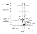
第1段階では、まずパージ制御弁10を全閉にした後(ステップ553)、大気口制御弁26を全閉にして(ステップ554)、燃料タンク8から吸気管5までのパージ通路を密閉状態にする。即ち、図5に示すように、まず大気口制御弁26が開放状態のときに、時刻T1でパージ制御弁10を全閉にすることで、燃料タンク8からパージ制御弁10までのパージ通路を大気口11を介して大気圧と同じ圧力に保ち、やや遅れて時刻T2で大気口制御弁26を全閉にすることで、大気圧に保たれた密閉パージ通路を形成する。
【0027】
そして、次のステップ555で、図5の時刻T2での燃料タンク内圧P1aを読み込み、タイマTをリセットスタートさせた後、ステップ556に進み、タイマTのカウント値が10秒以上になったか否かを判定する。10秒経過前であれば、ステップ557に進み、第1フラグF1を「1」にセットして本ルーチンを終了する。
【0028】
これ以後、第2段階の処理となる。この第2段階では、ステップ550で「Yes」と判定されるようになる。この段階で、再び故障診断ルーチンの処理が開始されると、ステップ501→503→511と進む。ステップ511では、PF=1(否1回目)となっているので、ステップ512に進む。ステップ512では、(Tpsが前回のステップ513で200sec以上となっていたので、)引き続きTpsが120sec以上となる条件を満足し、ステップ515→550→556→……と進み、これを繰り返す。この間、燃料タンク内圧力センサ19の検出値は、図5の時刻T2から時刻T3の間において、燃料タンク8内での燃料蒸発ガスの発生量に応じて0mmHgから上昇する。
【0029】
その後、時刻T2(P1aの検出時点)から10秒が経過すると、図4のステップ558に進み、燃料タンク内圧力センサ19からの入力信号を読み込んで、このときの燃料タンク内圧P1bを記憶し、続くステップ559で、10秒間の圧力変化量△P1を算出した後、ステップ560で、第1フラグF1をリセットする。これによって第2段階の処理が終了し、第3段階へ移る。
【0030】
この第3段階では、まずステップ561で、パージ制御弁10を全閉から全開状態に切り換えると共に、タイマTをリセットスタートする。ここで、パージ制御弁10が全開されることにより、それ以前の大気圧下の密閉パージ通路内に吸気管負圧を導入し始める(図5の時刻T3)。従って、パージ通路に圧力漏れ等による異常がなければ、燃料タンク内圧力センサ19の検出値は下降し始める。
【0031】
次のステップ562では、この燃料タンク内圧力センサ19からの入力信号に基づいて燃料タンク内圧Ptが−20mmHg以下になったか否かを判定し、Pt>−20mmHgであれば、ステップ572に進み、パージ制御弁10の全開後10秒が経過したか否かを判定する。10秒経過前であれば、ステップ577に進み、第2フラグF2を「1」にセットする。この後、ステップ578で、空燃比補正係数FAFが±20%以内であるか否かを判定し、FAFが±20%以内であれば、ステップ579に進んで、大気圧PAと吸気管圧力Pbとの差圧が所定値(例えば150mmHg)以上であるか否かを判定する。
【0032】
これらステップ578,579のいずれかが「No」と判定された場合、つまり空燃比補正係数FAFが±20%を越えたとき、又は吸気管圧力Pbとの差圧が所定値(例えば150mmHg)未満のときには、ステップ504に進む。一方、ステップ578,579の判定が共に「Yes」の場合には、そのまま本ルーチンを終了する。
【0033】
この場合、ステップ577で、第2フラグF2が「1」にセットされることで、次回以降の本ルーチン実行時には、ステップ550で「No」、ステップ551で「Yes」と判定されるようになり、ステップ501→503→511→512→515→550→551→ステップ562→……と処理を繰り返す。この状態は、ステップ562またはステップ572が「Yes」となると終了する。ステップ572の方が先に「Yes」となった場合には、燃料タンク8から吸気管5までのパージ通路のどこかに閉塞部分があることを意味し、ステップ573で、パージ系詰りフラグFcloseを「1」に設定し、続くステップ574で、警告ランプ33を点灯する。
【0034】
一方、ステップ562の方が先に「Yes」となった場合には、ステップ563に進んで、第2のフラグF2をリセットし、続くステップ564で、パージ制御弁10を再び全閉にした後、ステップ565で、燃料タンク内圧力センサ19からの入力信号を読み込んで、パージ通路を負圧密閉状態にした直後の燃料タンク内圧P2aを記憶すると共に、タイマTをリセットスタートする。これによって、第3段階から第4段階に移行する。
【0035】
上記ステップ563〜565の処理が実行されることにより、図5に示すように、時刻T4で密閉パージ通路内は−20mmHgの負圧状態に調整された状態となる。これ以後、燃料タンク内圧力センサ19の検出値は、時刻T4から時刻T5の間で燃料タンク8内での燃料蒸発ガスの発生量に応じて−20mmHgから上昇していくことになる。
【0036】
そして、次のステップ566で、P2aの読み込み後、10秒が経過したか否かを判定し、10秒経過前は、ステップ575に進み、第3のフラグF3を「1」に設定して本ルーチンを終了する。これにより、次回以降の本ルーチン実行時には、ステップ550,551で「No」、ステップ552で「Yes」と判定されるようになり、ステップ501〜552→ステップ566→……と処理を繰り返す。
【0037】
この後、P2aの読み込みから10秒が経過すると、ステップ568に進み、燃料タンク内圧力センサ19からの入力信号を読み込んで、時刻T5での燃料タンク内圧P2bを記憶し、密閉後10秒間の圧力変化量△P2(=P2b−P2a)を計算する(ステップ569)。この後、ステップ570で、次の(1)式で示されたリーク判定条件に基づいてリークがあるか否かを判定する。
【0038】
△P2>α・△P1+β ……(1)
ここで、αは大気圧と負圧の違いによる燃料蒸発量の差を補正する係数、βは燃料タンク内圧力センサ19の検出精度、大気口制御弁26の圧力漏れなどを補正する係数である。上記(1)式を満たせば、「リーク有り」と判定される。即ち、燃料タンク8からパージ制御弁10までの密閉区間にリーク原因があるならば、正圧下では密閉区間から大気中への流出が起こる一方、負圧下では大気中から密閉区間への空気の流入が起こる。従って、「(大気圧下の圧力変化量ΔP1)=(燃料タンク8からの燃料蒸発ガスの発生量)−(密閉区間から大気中への流出量)」よりも「(負圧下の圧力変化量△P2)=(燃料タンク8からの燃料蒸発ガスの発生量)+(大気中から密閉区間への流入量)」の方が大きくなる。この関係から、上記(1)式のリーク判定条件が導き出されたのである。
【0039】
上記(1)式のリーク判定条件を満足する場合、つまりステップ570で「リーク有り」と判定された場合には、燃料タンク8から吸気管5までのパージ通路のどこかにリーク原因となる部分があることを意味し、ステップ576で、パージ通路リークフラグFleakを「1」に設定し、続くステップ574で、警告ランプ33を点灯する。一方、ステップ570で「No」と判定された場合、つまりリークが発生していない場合には、ステップ571に進み、第1〜第3の各フラグF1〜F3を強制的にリセットして本ルーチンを終了する。
【0040】
ところで、F0=1(異常検出中)、つまり、ステップ513の第2異常判定条件成立後において、異常検出を中止したときについて説明する。F0=1(異常検出中)のときに、第1異常判定条件が不成立になったとき(つまり、ステップ503が「No」と判定されたとき)、空燃比補正係数FAFが±20%を越えたとき(つまり、ステップ578が「No」と判定されたとき)、又は大気圧PAと吸気管圧力Pbの差圧が所定値(例えば150mmHg)未満のとき(つまり、ステップ579が「No」と判定されたとき)は、ステップ504に進む。ステップ504で、F0=1(異常検出中)であったので、パージ実行積算時間Tps=0にリセットし(ステップ505)、F0←0(不成立)にし、ステップ580→581→571で本ルーチンを終了し、これを繰り返す。
【0041】
続いて、故障診断ルーチンの処理が開始され、ステップ501→503と進む。ステップ503で第1異常判定条件が成立すると(又は成立に変わると)、ステップ511に進む。このときPF=1(否1回目)であるので、ステップ512に進み、Tpsが120sec以上に達すると、F0←1にして、以後同様な異常検出の処理を実行する。
つまり、この場合は、始動後に必要とするパージ実行積算時間(又は積算パージ量)を経過してから、異常検出が中断されたので、キャニスタのパージを初期の必要パージ実行積算時間(例えば200sec)より短い時間(例えば120sec)だけ行ってから、再度異常検出するようにして、異常検出頻度を上げるようにする。
【0042】
また、途中で、ステップ578,579がともに「Yes」となると、再び故障診断ルーチンの処理が開始され、ステップ501→503→511に進む。このとき、同様に、PF=1(否1回目)であるので、ステップ512に進み、すでにTpsが120sec以上となっているので、F0←1にして、以後同様な異常検出の処理を実行する。
つまり、この場合も、始動後に必要とするパージ実行積算時間(又は積算パージ量)を経過してから、異常検出が中断されたので、キャニスタのパージを初期の必要パージ実行積算時間(例えば200sec)より短い時間(例えば120sec)だけ行ってから、再度異常検出するようにして、異常検出頻度を上げるようにする。
【0043】
また、ステップ579で、故障診断実行中の大気圧と吸気管圧力との差圧が所定値以上のときに故障診断を実行するようにしたので、故障診断時に燃料ガスパージシステム内に十分な吸気管負圧を導入することができて、故障診断精度が一層向上する。
【0044】
また、ステップ513で、機関始動後のパージ実行積算時間(又は積算パージ量)が所定値以上のときに故障診断を実行するようにしたので、キャニスタ内の燃料蒸発ガスの残留量が十分に少なくなっているときに故障診断を実行することができて、故障診断時の吸気管内への燃料蒸発ガスの流入量を少なくすることができ、オーバーリッチによるドライバピリティやエミッションの悪化を防止する。
【0045】
また、ステップ578で、空燃比フィードバック補正量が所定値以内で空燃比制御が安定しているときに故障診断を実行するようにしたので、故障診断によるオーバーリッチを防止できて、ドライバビリティやエミッションの悪化を防止する。
【0046】
また、ステップ503で、内燃機関の運転状態が安定しているときに故障診断を実行するようにしているので、運転状態が不安定な状態で故障診断する場合と比較してドライバビリティやエミッションの悪化を防止する。
【0047】
実施の形態1では、異常検出中(異常検出開始から異常検出終了するまでの間)、つまり、始動後パージ実行積算時間(ステップ513)後で異常検出を中断した場合、上記パージ実行積算時間をクリアする。すなわち図2,図3及び図4において、ステップ550の異常検出処理開始からステップ570の異常検出終了までの間で、ステップ503の判定がNoになった時、ステップ578,または579の判定がNoになった時、ステップ513判定の始動後パージ実行積算時間Tpsをクリアして、上記中断後のステップ513判定の判定値を始動後の値(例えば、200s)より短い時間、例えば、120sへ切り替えるようにする。
【0048】
このように、始動後に必要とするパージ実行積算時間(又は積算パージ量)を経過してから、異常検出が中断された場合は、キャニスタのパージを初期の必要パージ実行積算時間より短い時間行ってから、再度異常検出するようにしたので、異常検出頻度を上げると共にドライバビリティやエミッションの悪化を防止することができる。
【0049】
実施の形態2.
実施の形態2では、図2のステップ513での判定の判定値TTPRG(例えば200s)を燃料タンク内温度、大気圧、や燃料残量(燃料レベル)に応じて適切に設定する。TTPRGを次で求める値に設定する。
TTPRG=CR×(1+CPa+CFL)
ここで、燃料タンク内温度に応じて設定される時間(判定値CR)は、例えば、図6の表により求められ、タンク内温度[℃]に対する時間(判定値CR) [s]に設定する。燃料タンク内温度が下がると燃料蒸発量が小さくなるための補正である。大気圧補正係数CPaや燃料残量補正係数CFLは、大気圧や燃料残量が小さくなると燃料蒸発量が多く、ドライバビリティや排気有害成分値への影響が大きいための補正である。大気圧とその補正係数CPaの関係は図7に示す。燃料残量とその補正係数CFLとの関係は図8に示す。このように、燃料タンク内温度、大気圧又は燃料残量(燃料レベル)に応じた適切な判定値にすることにより、始動後に必要とするパージ実行積算時間(又は積算パージ量)を適切にすることができる。
【0050】
また、実施の形態2を実施の形態1に適用して、始動後に必要とするパージ実行積算時間(又は積算パージ量)を適切にすることができる。このとき、図2のステップ512のTpsは、ステップ513のTpsより短くする。
【0051】
実施の形態3.
燃料の給油を行うと、給油により燃料蒸発量は確実に増加するため、キャニスタ9のパージを通常よりも充分にする必要がある。そのため、実施の形態3では、給油後のパージ積算時間(積算パージ量)を、通常の条件より長い時間とし、キャニスタ9のパージを充分に実行し、ドライバビリティやエミッションの悪化を防止するようにした。
【0052】
図9は給油したか否か、つまり給油有か否かを判定する燃料給油判定フローチャートである。このフローチャートはキースイッチOFFでも動作している。給油判定処理を開始すると、ステップ691で車両停止か車両停止が所定時間以上継続しているかを、車速センサ29、又はECU20内蔵のタイマと合わせて計測し、「Yes」であれば、ステップ692で所定時間に燃料レベルが所定量以上増加したかを、燃料レベルゲージ27とタイマで計測し、「Yes」であれば、ステップ693で給油有りと判定し、ステップ694でフラグFF←1(給油有)をセットし記憶する。再び給油判定処理を例えば、25msecで繰返し実施し、再び給油有りと判定しても、FF=1(給油有)は変化しない。なお、FF←0への変更は後述するフローチャートで行われる。また、ステップ691又はステップ692でいずれかが「No」であれば、ステップ695で給油判定解除とされる。なお、車両停止は、キースイッチOFFで検出してもよい。
【0053】
図10,図3及び図4は実施の形態3における燃料ガスパージシステムの故障診断を示すフローチャートで、図10,図3及び図4を合わせて全体のフローチャートを示す。図3及び図4は実施の形態1と同じであるので、図10を中心に説明する。なお、図10で、図2と同一の符号は同一又は相当する意味を表し、図2と同一ステップ番号は同一又は相当するステップを表す。
【0054】
図10で、この故障診断ルーチンの処理を開始するため(異常検出スタート)、キースイッチのOFF→ON変化を検出すると(ステップ501、Yes)、ステップ522の処理を実行し、ステップ503に進む。
ステップ522では、
パージ実行積算時間Tps=0、
F0,F1,F2,F3 ← 0 にセットする。
ここで、Tpsは、パージ実行積算時間で、Tps=0はこれを0にすることを示す。
なお、F0,F1,F2,F3についても、実施の形態1と同様にセットされる。
ステップ501では、キースイッチのOFF→ON変化のとき「Yes」で、キースイッチがON状態継続のときは「No」で、ステップ503に進む。
【0055】
ステップ503(第1異常判定条件検出手段)で、第1異常判定条件が成立しているか否かを検出する。第1異常判定条件(実施の形態1と同じ)が成立していると、ステップ523に進むが、第1異常判定条件が不成立のときには、故障診断を禁止し、ステップ504に進む。ステップ504からは、実施の形態1と同様にして、ステップ580(図4)に進み、同様にして、ステップ571に進み本ルーチンを終了する。
【0056】
再び、故障診断ルーチンの処理が開始されると(異常検出スタート)、キースイッチがON状態を継続しておれば、ステップ501は「No」であるので、ステップ503に進む。第1異常判定条件が成立すると(ステップ503、Yes)、ステップ523で給油有か否かを図9のフラグFFでチェックする。FF=0(給油無し)であれば、ステップ513(第2異常判定条件検出手段)に進み。始動後のパージ実行積算時間が所定時間(例えば200秒)以上になったか否かを判定し、ステップ513が「No」の場合、つまりパージが不十分の場合には、故障診断を禁止し、実施の形態1と同様に、ステップ506からステップ571を経て本ルーチンを終了する。
【0057】
次に、キャニスタ9のパージが十分に行われている場合には(ステップ513、Yes)、F0←1(異常検出中)とし(ステップ515)とし、図3のステップ550から図3,図4のルーチンを実施の形態1と同様に実施する。その間、FF=0であれば、ステップ523はYesとなり、ステップ513に進んで、ルーチンが繰り返される。
【0058】
ところで、車両が燃料を給油すると、これを図9の燃料給油判定処理で判定し、FF←1にセットされ、記憶される。給油後にキースイッチをOFF→ONすると、異常検出スタートし、ステップ501がYesとなり、ステップ522で、パージ実行積算時間Tps=0、F0,F1,F2,F3←0にセットする。続いて、ステップ503の第1異常判定条件が成立すると、ステップ523に進み、フラグFFの記憶値をチェックする。FF=1であるので、ステップ523はNoとなり、ステップ524に進む。ここで、第2異常判定条件として、パージ実行積算時間が通常より長い、例えば300sec以上か否か判断する。300secに達していないときは、ステップ506からステップ571を経てルーチンを終了する。300secに達したときは、ステップ525で、図9のフラグFFを0にリセットし記憶し、ステップ515に進み、ステップ550から図3,図4のルーチンを実施の形態1と同様に実施する。
【0059】
このようにして、実施の形態3では、給油後のパージ積算時間(積算パージ量)を、通常の条件より長い時間とし、キャニスタ9のパージを充分に実行してから、故障診断を開始するようにして、ドライバビリティやエミッションの悪化を防止するようにした。
【0060】
また、実施の形態2の判定値TTPRGを実施の形態3に適用して、パージ実行積算時間(又は積算パージ量)を適切にすることができる。このときにおいても、図10のステップ524のTpsは、ステップ513のTpsより長くしておく。
【0061】
実施の形態4.
実施の形態4は、パージ実行が所定時間以上継続して実施されていない場合は、それまでのパージ実行積算時間をクリアして、改めてパージ実行積算を開始するようにしたものである。パージ実行を実施していないときは、パージのデューティ制御量が0のときである。また、パージ実行を実施しないときは、機関アイドル運転時であり、又は、吸気管5の負圧が小さくなりパージ制御弁10を全開にしてもパージが導入できない(例えば、機関高負荷運転の)ときである。
【0062】
図11は実施の形態4に係わるパージ実行積算時間処理を示すフローチャートである。これは実施の形態1〜3のパージ実行積算時間処理(積算パージ計測手段)にも適用できるものである。パージ実行積算時間処理が開始されると、ステップ701でパージのデューティ制御量が0か否かをECU20で検出し、Yesであれば、ステップ705に進む。ステップ701がNoであれば、ステップ702に進む。ステップ702で、スロットルバルブ3が全閉(機関アイドル運転)であるか否かを、スロットル開度センサ12で検出し、Yes(全閉)であれば、ステップ705に進む。ステップ702がNoであれば、ステップ703に進む。ステップ703で、吸気管負圧小(例えば100mmHg以下)であるか否かを吸気管圧力センサ18で検出し、Yesであれば、ステップ705に進む。
【0063】
ステップ701,702,又は703でYesであれば、パージを停止しており、又はパージを停止させているので、ステップ705でそのパージ停止継続時間を積算する。ステップ706でそのパージ停止継続時間が例えば45secより少ない状態のとき(No)、ENDとなり、再びパージ実行積算時間処理を実行する(例えば、25msec毎)。ステップ706でそのパージ停止継続時間が例えば45sec以上になる(Yes)と、ステップ707でそれまでのパージ実行積算時間をクリアして、ENDになり、再びパージ実行積算時間処理を実行する。
一方、ステップ701,702,及び703がNoであれば、ステップ704で、パージ実行時間を積算すると共に、それまでのパージ停止継続時間をクリアし、ENDになり、再びパージ実行積算時間処理を実行する。
【0064】
このように、パージ実行を所定時間以上継続して実施していない場合、すなわち、パージのデューティ制御量が0のとき、機関アイドル運転状態(スロットルバルブ全閉)のとき、吸気管の負圧が小さい(例えば100mmHg)ときが、所定時間以上継続した場合、上記パージ実行積算時間をクリアするようにした。
【0065】
これは、パージ実行を所定時間以上継続して実施していないと、燃料蒸発量が多くなっているので、このときに、異常検出処理を行って、機関に悪影響が及ぶのを防止したものである。すなわち、これによって、キャニスタのパージが不十分な状態で異常検出を開始し、パージ制御弁を開いて吸気管負圧を燃料ガスパージシステム内に導入した場合、キャニスタ内に残っていた比較的多量の燃料蒸発ガスが吸気管内に流入してしまうことを防止できるので、オーバーリッチによる、ドライバビリティやエミッションの悪化が防止できる。
【0066】
【発明の効果】
以上説明したように、この発明の内燃機関における故障診断機能を有する燃料ガスパージシステムによれば、燃料タンクと吸気管とを連通するパージ通路の途中に設けたキャニスタの吸着体で燃料タンク内で発生した燃料ガスを吸着し、内燃機関の運転状態に応じてパージ制御弁を開閉することにより、吸着された燃料ガスを吸気管内に導入して燃料の蒸散を防止する燃料蒸散防止装置と、上記内燃機関の運転状態を検出する複数のセンサと、上記複数のセンサからの運転状態情報に基づいて上記燃料蒸散防止装置の第1異常判定条件の成立を検出する第1異常判定条件検出手段と、上記キャニスタに設けられた大気口を閉塞する大気口閉塞弁と、上記パージ制御弁及び上記大気口閉塞弁を共に閉じて上記燃料蒸散防止装置全体を一つの密閉区間とする密閉化手段と、上記パージ制御弁を開制御している積算時間または上記開制御に基づくパージ積算流量により積算パージ量を計測する積算パージ計測手段と、上記第1異常判定条件が成立し、機関始動後の積算パージ量が第1の所定値以上のときに第2異常判定条件成立とする第2異常判定条件検出手段と、上記燃料タンク内圧力を検出する燃料タンク内圧力センサと、並びに、上記燃料タンク内圧力センサの検出結果に基づいて上記燃料蒸散防止装置の異常を検出する異常検出手段とを備え、上記第2異常判定条件成立後に異常検出を中断した時に、上記積算パージ量をクリアすると共に、次の上記第2異常判定条件の成立には上記積算パージ量が上記第1の所定値より短い第2の所定値以上のときに異常判定条件成立とするようにしたので、異常検出が中断された場合はキャニスタのパージを必要とするより短い時間実行してから、再異常検出するようにしたため、異常検出頻度を上げると共にドライバビリティやエミッションの悪化を防止することができる。
【0067】
また、この発明の内燃機関における故障診断機能を有する燃料ガスパージシステムによれば、燃料給油判定手段を備え、上記燃料給油判定手段で燃料を給油したと判定したときは、上記第2異常判定条件の成立には上記積算パージ量が上記第1の所定値より長い第3の所定値以上のときに異常判定条件成立とするようにしたので、燃料を給油したと判定したときは、燃料の給油による燃料蒸発ガスの流入によるオーバーリッチの発生を防止し、ドライバビリティやエミッションの悪化を防止することができる。
【0068】
さらにまた、この発明の内燃機関における故障診断機能を有する燃料ガスパージシステムによれば、上記燃料給油判定手段は、車両の速度を検出する車速センサと、上記燃料タンク内に残っている燃料残量を検出する燃料レベルゲージと、タイマとを含んで、燃料の給油を判定するようにしたので、燃料を給油したと判定したときは、燃料の給油による燃料蒸発ガスの流入によるオーバーリッチの発生を防止し、ドライバビリティやエミッションの悪化を防止することができる。
【図面の簡単な説明】
【図1】 この発明の実施の形態1による故障診断機能を有する燃料ガスパージシステムを示す構成図である。
【図2】 実施の形態1における燃料ガスパージシステムの故障診断を示すフローチャートの一部である。
【図3】 実施の形態1における燃料ガスパージシステムの故障診断を示すフローチャートの一部である。
【図4】 実施の形態1における燃料ガスパージシステムの故障診断を示すフローチャートの一部で、図2と図3とを合わせて全体のフローチャートを示す。
【図5】 故障診断時のパージ制御弁と大気口制御弁の開閉、並びに燃料タンク内圧の変化の関係を説明するタイムチャートである。
【図6】 実施の形態2におけるタンク内温度[℃]に対するパージの実行時間(判定値)[s]を示す図である。
【図7】 大気圧とその補正係数CPaの関係を示す図である。
【図8】 燃料残量とその補正係数CFLの関係を示す図である。
【図9】 実施の形態3における給油有であるかを判定する給油判定フローチャートである。
【図10】 実施の形態3における燃料ガスパージシステムの故障診断を示すフローチャートの一部で、図2と図3とを合わせて全体のフローチャートを示す。
【図11】 実施の形態4に係わるパージ実行積算時間処理を示すフローチャートである。
【符号の説明】
1 エアクリーナ 2 エアフローセンサ
3 スロットルバルブ 4 サージタンク
5 吸気管 6 エンジン
7 インジェクタ 8 燃料タンク
9 キャニスタ 10 パージ制御弁
11 大気口 12 スロットル開度センサ
13 吸気温度センサ 14 水温センサ
15 排気管 16 空燃比センサ
17 クランク角センサ 18 吸気管圧力センサ
19 燃料タンク内圧力センサ 20 電子制御ユニット「ECU」
21 CPU 22 ROM
23 RAM 24 入出力インターフェイス
25 駆動回路 26 大気口制御弁
27 燃料レベルゲージ 28 車両
29 車速センサ 30 大気圧センサ
31 外気温度センサ 32 燃料タンク内温度センサ
33 警告ランプ 34 キースイッチ
35 バッテリ電圧。[0001]
BACKGROUND OF THE INVENTION
The present invention relates to diagnosing the presence or absence of a failure in a fuel gas purge system that purges (releases) fuel evaporative gas adsorbed in a canister into an intake pipe of an internal combustion engine.
[0002]
[Prior art]
As a conventional failure diagnosis device for a fuel gas purge system, a condition for when the purge execution integrated time or the integrated purge amount after engine startup becomes equal to or greater than a predetermined value is added to the failure diagnosis condition. Under these conditions, it is determined whether or not the canister is sufficiently purged, and the failure diagnosis is executed when the remaining amount of the fuel evaporative gas in the canister is sufficiently small. As a result, over-rich due to the inflow of fuel evaporative gas into the intake pipe at the time of failure diagnosis does not occur, and drivability and emission are prevented from deteriorating (for example, Patent Document 1). Moreover, there exists
[0003]
[Patent Document 1]
JP-A-9-177617
[Patent Document 2]
Japanese Patent Laid-Open No. 11-22564
[0004]
[Problems to be solved by the invention]
In the conventional failure diagnosis apparatus for a fuel gas purge system, even when abnormality detection is interrupted and abnormality detection is performed again, the canister purge integration time is performed for the same time, so there is a problem that the abnormality detection frequency cannot be increased.
[0005]
The present invention has been made to solve the above-described problems. When the abnormality detection is interrupted, the abnormality is detected again after being executed for a shorter period of time that requires the canister purge. Therefore, it is intended to increase the frequency of abnormality detection and to obtain what prevents drivability and emission from deteriorating.
Further, when it is determined that the fuel has been refueled, an attempt is made to prevent the occurrence of over-rich due to the inflow of fuel evaporative gas due to the refueling of the fuel and to prevent the deterioration of drivability and emission.
Furthermore, when the period during which the purge by the purge control valve is not introduced continues for a predetermined time or more, the accumulated purge amount is cleared to prevent the occurrence of over-rich due to the inflow of a large amount of fuel evaporative gas, and drivability and emissions are reduced. We want to get something that prevents deterioration.
[0006]
[Means for Solving the Problems]
A fuel gas purge system having a failure diagnosis function in an internal combustion engine according to the present invention, adsorbs fuel gas generated in the fuel tank with a canister adsorbent provided in the middle of a purge passage communicating the fuel tank and the intake pipe, By opening and closing the purge control valve in accordance with the operating state of the internal combustion engine, a fuel transpiration preventing device that introduces the adsorbed fuel gas into the intake pipe to prevent the transpiration of the fuel and the operating state of the internal combustion engine are detected. A plurality of sensors, first abnormality determination condition detection means for detecting establishment of a first abnormality determination condition of the fuel transpiration prevention device based on operating state information from the plurality of sensors, and an air outlet provided in the canister And a sealing means for closing the purge control valve and the air port closing valve together to make the entire fuel evaporation prevention device one sealed section. , Integrated purge measuring means for measuring the integrated purge amount based on the integrated time during which the purge control valve is controlled to open or the integrated purge flow rate based on the open control, and the integrated value after starting the engine when the first abnormality determination condition is satisfied A second abnormality determination condition detecting means for establishing a second abnormality determination condition when the purge amount is equal to or greater than a first predetermined value; a fuel tank pressure sensor for detecting the fuel tank internal pressure; An abnormality detecting means for detecting an abnormality of the fuel transpiration prevention device based on a detection result of the pressure sensor.
[0007]
When the abnormality detection is interrupted after the second abnormality determination condition is satisfied, the accumulated purge amount is cleared, and the accumulated purge amount is shorter than the first predetermined value for the next satisfaction of the second abnormality determination condition. The abnormality determination condition is established when the value is equal to or greater than the second predetermined value.
[0008]
Also,When it is determined by the fuel supply determination means that the fuel has been supplied, the integrated purge amount is longer than the first predetermined value to satisfy the second abnormality determination condition.ThirdThe abnormality determination condition is established when the value is equal to or greater than a predetermined value.
[0009]
Furthermore, the fuel refueling determination means includes a vehicle speed sensor that detects the speed of the vehicle, a fuel level gauge that detects the remaining amount of fuel remaining in the fuel tank, and a timer, and determines fuel refueling. It is what you do.
[0010]
DETAILED DESCRIPTION OF THE INVENTION
FIG. 1 is a block diagram showing a fuel gas purge system having a failure diagnosis function according to
[0011]
The
[0012]
The
[0013]
The
[0014]
The fuel evaporation prevention device prevents the evaporation of fuel by opening and closing the
[0015]
The fuel evaporation prevention control means in the
[0016]
The
[0017]
Further, the
[0018]
Further, the
[0019]
Next, failure diagnosis of the fuel gas purge system will be described. In the first embodiment, in particular, when the abnormality detection is interrupted after the purge execution integrated time (or integrated purge amount) required after starting has elapsed, the canister purge is performed from the initial required purge execution integrated time. After a short time, the abnormality detection frequency is increased by detecting the abnormality again. 2, 3 and 4 are flowcharts showing failure diagnosis of the fuel gas purge system in the first embodiment, and FIG. 2, FIG. 3 and FIG. FIG. 5 is a time chart for explaining the relationship between the opening and closing of the purge control valve and the atmospheric port control valve and the change in the fuel tank internal pressure during failure diagnosis.
[0020]
The failure diagnosis of the fuel gas purge system is repeatedly executed at predetermined time intervals (for example, every 25 msec) according to the flowcharts of FIGS. 2, 3 and 4 when the
[0021]
In
PF ← 0,
Integrated purge execution time Tps = 0,
Set F0, F1, F2, F3 ← 0.
Here, PF is a flag indicating whether or not it is the first time after the key switch changes from OFF to ON, and PF = 0 indicates the first time.
Tps is the purge execution integration time, and Tps = 0 indicates that this is set to 0.
F0 is a flag indicating whether or not an abnormality is being detected (second abnormality determination condition is established), and F0 = 0 indicates a non-established state.
F1, F2, and F3 are flags indicating the processing state level of the abnormality detection, and all 0 indicates an initial state that has not reached the processing state of the abnormality detection.
In
[0022]
In step 503 (first abnormality determination condition detection means), it is detected whether or not the first abnormality determination condition is satisfied. Here, the first abnormality determination condition is satisfied when the engine operating state is stable. Specifically, intake air amount = 5.0 to 40 g / s, intake air temperature = −10 to 70 ° C., cooling water temperature at start-up = −7.5 to 35 ° C., 700 seconds or more after start, battery voltage 10V or more The determination condition is that the air-fuel ratio feedback is being executed, and the first abnormality determination condition is satisfied when all of these conditions are satisfied, and the process proceeds to step 511. If the first abnormality determination condition is not satisfied, the failure diagnosis is performed. Prohibit and proceed to step 504. In
[0023]
Proceeding to step 580 in FIG. 4, the air
[0024]
When the process of the failure diagnosis routine is started again (abnormality detection start), if the key switch continues to be in the ON state,
[0025]
Next, when the
[0026]
In the first stage, first, the
[0027]
Then, in the
[0028]
Thereafter, the second stage processing is performed. In this second stage, “Yes” is determined in
[0029]
Thereafter, when 10 seconds elapse from time T2 (detection time of P1a), the process proceeds to step 558 in FIG. 4 and an input signal from the fuel tank
[0030]
In the third stage, first, in
[0031]
In the
[0032]
When any of these
[0033]
In this case, when the second flag F2 is set to “1” in
[0034]
On the other hand, if
[0035]
As a result of the processing in
[0036]
Then, in the
[0037]
Thereafter, when 10 seconds have elapsed from reading of P2a, the process proceeds to step 568, the input signal from the fuel tank
[0038]
ΔP2> α · ΔP1 + β (1)
Here, α is a coefficient for correcting the difference in fuel evaporation due to the difference between the atmospheric pressure and the negative pressure, and β is a coefficient for correcting the detection accuracy of the
[0039]
If the leak determination condition of the above equation (1) is satisfied, that is, if “leak” is determined in
[0040]
By the way, F0 = 1 (during abnormality detection), that is, the case where abnormality detection is stopped after the second abnormality determination condition is established in
[0041]
Subsequently, the process of the failure diagnosis routine is started, and the process proceeds from
That is, in this case, since the abnormality detection is interrupted after the purge execution integrated time (or integrated purge amount) required after the start has elapsed, the initial purge execution integrated time (for example, 200 sec) is purged. The abnormality detection frequency is increased by performing the abnormality detection again after a shorter time (for example, 120 seconds).
[0042]
On the other hand, when both
That is, also in this case, since the abnormality detection is interrupted after the purge execution integrated time (or integrated purge amount) required after the start has elapsed, the initial purge execution integrated time (for example, 200 sec) is purged. The abnormality detection frequency is increased by performing the abnormality detection again after a shorter time (for example, 120 seconds).
[0043]
In
[0044]
In
[0045]
In
[0046]
Further, in
[0047]
In the first embodiment, when the abnormality detection is interrupted after the abnormality is detected (between the abnormality detection start and the abnormality detection end), that is, after the purge execution integration time after start (step 513), the purge execution integration time is set to clear. That is, in FIG. 2, FIG. 3 and FIG. 4, when the determination in
[0048]
As described above, when the abnormality detection is interrupted after the purge execution accumulated time (or accumulated purge amount) required after the start has elapsed, the canister is purged for a time shorter than the initial required purge execution accumulated time. Therefore, the abnormality detection is performed again, so that the abnormality detection frequency can be increased and the drivability and emission can be prevented from deteriorating.
[0049]
In the second embodiment, the determination value TTPRG (for example, 200 s) at
TTPRG = CR × (1 + CPa + CFL)
Here, the time (determination value CR) set according to the temperature in the fuel tank is obtained from the table of FIG. 6, for example, and is set to the time (determination value CR) [s] with respect to the tank internal temperature [° C.]. . This is a correction for reducing the amount of fuel evaporation as the temperature in the fuel tank decreases. The atmospheric pressure correction coefficient CPa and the remaining fuel amount correction coefficient CFL are corrections because the amount of fuel evaporation increases as the atmospheric pressure or the remaining fuel amount decreases, and the influence on drivability and exhaust harmful component values is large. The relationship between atmospheric pressure and its correction coefficient CPa is shown in FIG. The relationship between the fuel remaining amount and its correction coefficient CFL is shown in FIG. In this way, by setting an appropriate determination value according to the temperature in the fuel tank, the atmospheric pressure, or the remaining amount of fuel (fuel level), the purge execution integrated time (or integrated purge amount) required after starting is made appropriate. be able to.
[0050]
Further, the second embodiment can be applied to the first embodiment, and the purge execution integrated time (or integrated purge amount) required after starting can be made appropriate. At this time, Tps in
[0051]
When the fuel is supplied, the fuel evaporation amount is surely increased by the fuel supply. Therefore, the
[0052]
FIG. 9 is a fuel refueling determination flowchart for determining whether or not refueling, that is, whether or not refueling is present. This flowchart operates even when the key switch is OFF. When the fuel supply determination process is started, it is measured in
[0053]
10, FIG. 3 and FIG. 4 are flow charts showing failure diagnosis of the fuel gas purge system in the third embodiment, and FIG. 10, FIG. 3 and FIG. 3 and 4 are the same as those of the first embodiment, and therefore, description will be made mainly with reference to FIG. 10, the same reference numerals as those in FIG. 2 represent the same or corresponding meanings, and the same step numbers as those in FIG. 2 represent the same or corresponding steps.
[0054]
In FIG. 10, in order to start the process of this failure diagnosis routine (abnormality detection start), when a key switch OFF → ON change is detected (
In
Integrated purge execution time Tps = 0,
Set F0, F1, F2, F3 ← 0.
Here, Tps is the purge execution integration time, and Tps = 0 indicates that this is set to 0.
Note that F0, F1, F2, and F3 are set in the same manner as in the first embodiment.
In
[0055]
In step 503 (first abnormality determination condition detection means), it is detected whether or not the first abnormality determination condition is satisfied. If the first abnormality determination condition (same as in the first embodiment) is satisfied, the process proceeds to step 523, but if the first abnormality determination condition is not satisfied, the failure diagnosis is prohibited and the process proceeds to step 504. From
[0056]
When the process of the failure diagnosis routine is started again (abnormality detection start), if the key switch continues to be in the ON state,
[0057]
Next, when the
[0058]
By the way, when the vehicle refuels, this is determined by the fuel refueling determination process of FIG. 9, and is set to FF ← 1 and stored. When the key switch is turned OFF → ON after refueling, abnormality detection starts,
[0059]
In this way, in the third embodiment, the purge integrated time (integrated purge amount) after refueling is set to a time longer than the normal condition, and the failure diagnosis is started after the
[0060]
Further, the determination value TTPRG of the second embodiment can be applied to the third embodiment to make the purge execution integrated time (or integrated purge amount) appropriate. Also at this time, Tps in
[0061]
In the fourth embodiment, when the purge execution is not continuously performed for a predetermined time or more, the purge execution integration time is cleared and the purge execution integration is started again. When the purge execution is not performed, the purge duty control amount is zero. Further, when the purge execution is not performed, it is during engine idle operation, or even if the negative pressure of the
[0062]
FIG. 11 is a flowchart showing purge execution integration time processing according to the fourth embodiment. This can also be applied to the purge execution integrated time processing (integrated purge measuring means) of the first to third embodiments. When the purge execution integration time process is started, the
[0063]
If YES in
On the other hand, if
[0064]
As described above, when the purge execution is not continuously performed for a predetermined time or more, that is, when the purge duty control amount is 0, or when the engine is idling (throttle valve fully closed), the negative pressure of the intake pipe is reduced. When the time of small (for example, 100 mmHg) continues for a predetermined time or longer, the purge execution integrated time is cleared.
[0065]
This is because the amount of fuel evaporation increases unless the purge execution is continued for a predetermined time or more. At this time, an abnormality detection process is performed to prevent adverse effects on the engine. is there. That is, when the abnormality detection is started in a state where the purge of the canister is insufficient, and the intake pipe negative pressure is introduced into the fuel gas purge system by opening the purge control valve, a relatively large amount remaining in the canister Since fuel evaporative gas can be prevented from flowing into the intake pipe, drivability and emission deterioration due to overriching can be prevented.
[0066]
【The invention's effect】
As described above, according to the fuel gas purge system having a failure diagnosis function in the internal combustion engine of the present invention, it is generated in the fuel tank by the adsorbent of the canister provided in the middle of the purge passage communicating the fuel tank and the intake pipe. A fuel transpiration prevention device that adsorbs the adsorbed fuel gas and opens and closes a purge control valve in accordance with the operating state of the internal combustion engine to introduce the adsorbed fuel gas into the intake pipe to prevent fuel transpiration, and the internal combustion engine A plurality of sensors for detecting the operating state of the engine, first abnormality determination condition detecting means for detecting establishment of a first abnormality determination condition of the fuel transpiration prevention device based on operating state information from the plurality of sensors, and The atmospheric port closing valve for closing the atmospheric port provided in the canister, the purge control valve, and the atmospheric port closing valve are both closed so that the entire fuel transpiration prevention device is hermetically sealed. And the first abnormality determination condition is met. The integrated purge measuring means for measuring the integrated purge amount based on the integrated time during which the purge control valve is opened or the integrated purge flow rate based on the open control. A second abnormality determination condition detecting means for establishing a second abnormality determination condition when the accumulated purge amount after engine startup is equal to or greater than a first predetermined value; a fuel tank pressure sensor for detecting the fuel tank pressure; And an abnormality detection means for detecting an abnormality of the fuel transpiration prevention device based on a detection result of the fuel tank pressure sensor, and when the abnormality detection is interrupted after the second abnormality determination condition is satisfied, the integrated purge In addition to clearing the amount, when the second abnormality determination condition is satisfied, the abnormality determination condition is satisfied when the integrated purge amount is equal to or greater than a second predetermined value that is shorter than the first predetermined value. As a result, if anomaly detection is interrupted, it is executed for a shorter period of time that requires a canister purge, and then the anomaly is detected again. This increases the frequency of anomaly detection and prevents deterioration of drivability and emissions. be able to.
[0067]
Further, according to the fuel gas purge system having a failure diagnosis function in the internal combustion engine of the present invention,A fuel refueling determination means;When it is determined that fuel has been supplied by the fuel supply determination means, an abnormality determination is made when the integrated purge amount is greater than or equal to a third predetermined value longer than the first predetermined value in order to satisfy the second abnormality determination condition. Since the condition is satisfied, when it is determined that the fuel is supplied, it is possible to prevent the occurrence of over-rich due to the inflow of the fuel evaporative gas due to the fuel supply, thereby preventing the drivability and the emission from deteriorating.
[0068]
Furthermore, according to the fuel gas purge system having a failure diagnosis function in the internal combustion engine of the present invention,The fuel refueling determination means includes a vehicle speed sensor for detecting the speed of the vehicle, a fuel level gauge for detecting the remaining amount of fuel remaining in the fuel tank, and a timer so as to determine fuel refueling. Therefore, when it is determined that the fuel has been refueled, it is possible to prevent the occurrence of over-rich due to the inflow of the fuel evaporative gas due to the fuel refueling, and to prevent the drivability and the emission from deteriorating.
[Brief description of the drawings]
FIG. 1 is a configuration diagram showing a fuel gas purge system having a failure diagnosis function according to
FIG. 2 is a part of a flowchart showing failure diagnosis of the fuel gas purge system in the first embodiment.
FIG. 3 is a part of a flowchart showing failure diagnosis of the fuel gas purge system in the first embodiment.
FIG. 4 is a part of a flowchart showing failure diagnosis of the fuel gas purge system in
FIG. 5 is a time chart for explaining the relationship between the opening and closing of the purge control valve and the air outlet control valve and the change in the fuel tank internal pressure during failure diagnosis.
6 is a diagram showing a purge execution time (determination value) [s] with respect to a tank internal temperature [° C.] in
FIG. 7 is a diagram showing the relationship between atmospheric pressure and its correction coefficient CPa.
FIG. 8 is a diagram showing the relationship between the remaining amount of fuel and its correction coefficient CFL.
FIG. 9 is a refueling determination flowchart for determining whether refueling is present in the third embodiment.
FIG. 10 is a part of a flowchart showing failure diagnosis of the fuel gas purge system in
FIG. 11 is a flowchart showing purge execution integration time processing according to the fourth embodiment.
[Explanation of symbols]
1
3
5
7
9
11
13 Intake
15
17
19 Fuel
21
23 RAM 24 I / O interface
25
27
29
31
33
35 Battery voltage.
Claims (3)
上記内燃機関の運転状態を検出する複数のセンサと、
上記複数のセンサからの運転状態情報に基づいて上記燃料蒸散防止装置の第1異常判定条件の成立を検出する第1異常判定条件検出手段と、
上記キャニスタに設けられた大気口を閉塞する大気口閉塞弁と、
上記パージ制御弁及び上記大気口閉塞弁を共に閉じて上記燃料蒸散防止装置全体を一つの密閉区間とする密閉化手段と、
上記パージ制御弁を開制御している積算時間または上記開制御に基づくパージ積算流量により積算パージ量を計測する積算パージ計測手段と、
上記第1異常判定条件が成立し、機関始動後の積算パージ量が第1の所定値以上のときに第2異常判定条件成立とする第2異常判定条件検出手段と、
上記燃料タンク内圧力を検出する燃料タンク内圧力センサと、並びに、
上記燃料タンク内圧力センサの検出結果に基づいて上記燃料蒸散防止装置の異常を検出する異常検出手段とを備え、
上記第2異常判定条件成立後に異常検出を中断した時に、上記積算パージ量をクリアすると共に、次の上記第2異常判定条件の成立には上記積算パージ量が上記第1の所定値より短い第2の所定値以上のときに異常判定条件成立とするようにした内燃機関における故障診断機能を有する燃料ガスパージシステム。By adsorbing the fuel gas generated in the fuel tank with the adsorbent of the canister provided in the middle of the purge passage communicating the fuel tank and the intake pipe, and opening and closing the purge control valve according to the operating state of the internal combustion engine, A fuel transpiration prevention device that introduces the adsorbed fuel gas into the intake pipe to prevent transpiration of the fuel;
A plurality of sensors for detecting the operating state of the internal combustion engine;
First abnormality determination condition detection means for detecting establishment of a first abnormality determination condition of the fuel transpiration prevention device based on operating state information from the plurality of sensors;
An air port closing valve for closing the air port provided in the canister;
A sealing means that closes both the purge control valve and the air port closing valve to make the entire fuel transpiration prevention device one sealed section;
An integrated purge measuring means for measuring an integrated purge amount by an integrated time during which the purge control valve is opened or a purge integrated flow rate based on the open control;
Second abnormality determination condition detection means for establishing a second abnormality determination condition when the first abnormality determination condition is satisfied and the integrated purge amount after engine startup is equal to or greater than a first predetermined value;
A fuel tank pressure sensor for detecting the fuel tank pressure, and
An abnormality detection means for detecting an abnormality of the fuel transpiration prevention device based on the detection result of the fuel tank pressure sensor,
When the abnormality detection is interrupted after the second abnormality determination condition is satisfied, the integrated purge amount is cleared, and for the next satisfaction of the second abnormality determination condition, the integrated purge amount is shorter than the first predetermined value. 2. A fuel gas purge system having a failure diagnosis function in an internal combustion engine, wherein an abnormality determination condition is satisfied when a predetermined value of 2 or more is satisfied.
Priority Applications (2)
| Application Number | Priority Date | Filing Date | Title |
|---|---|---|---|
| JP2003185132A JP4090952B2 (en) | 2003-06-27 | 2003-06-27 | Fuel gas purge system with fault diagnosis function in internal combustion engine |
| US10/704,720 US6862516B2 (en) | 2003-06-27 | 2003-11-12 | Fuel gas purge system having failure diagnostic function in internal combustion engine |
Applications Claiming Priority (1)
| Application Number | Priority Date | Filing Date | Title |
|---|---|---|---|
| JP2003185132A JP4090952B2 (en) | 2003-06-27 | 2003-06-27 | Fuel gas purge system with fault diagnosis function in internal combustion engine |
Publications (2)
| Publication Number | Publication Date |
|---|---|
| JP2005016474A JP2005016474A (en) | 2005-01-20 |
| JP4090952B2 true JP4090952B2 (en) | 2008-05-28 |
Family
ID=33535395
Family Applications (1)
| Application Number | Title | Priority Date | Filing Date |
|---|---|---|---|
| JP2003185132A Expired - Fee Related JP4090952B2 (en) | 2003-06-27 | 2003-06-27 | Fuel gas purge system with fault diagnosis function in internal combustion engine |
Country Status (2)
| Country | Link |
|---|---|
| US (1) | US6862516B2 (en) |
| JP (1) | JP4090952B2 (en) |
Families Citing this family (6)
| Publication number | Priority date | Publication date | Assignee | Title |
|---|---|---|---|---|
| JP4419740B2 (en) * | 2004-07-23 | 2010-02-24 | トヨタ自動車株式会社 | In-tank canister system failure diagnosis apparatus and failure diagnosis method |
| JP4569665B2 (en) * | 2008-05-13 | 2010-10-27 | トヨタ自動車株式会社 | Internal combustion engine control system |
| US8166795B2 (en) * | 2009-11-30 | 2012-05-01 | Eaton Corporation | Out-of-range sensor recalibration |
| JP5965384B2 (en) * | 2013-12-27 | 2016-08-03 | 富士重工業株式会社 | Fuel pressure sensor characteristic abnormality diagnosis device |
| DE102014217195A1 (en) * | 2014-08-28 | 2016-03-03 | Continental Automotive Gmbh | Method for leak diagnosis in a fuel tank system |
| US9541024B2 (en) * | 2015-03-18 | 2017-01-10 | Ford Global Technologies, Llc | Fuel level indication noise monitor |
Family Cites Families (8)
| Publication number | Priority date | Publication date | Assignee | Title |
|---|---|---|---|---|
| JP2666557B2 (en) * | 1990-10-15 | 1997-10-22 | トヨタ自動車株式会社 | Failure diagnosis device for evaporation purge system |
| JP3239436B2 (en) | 1991-09-13 | 2001-12-17 | 株式会社デンソー | Abnormality detection device for fuel evaporation prevention device |
| JPH0921359A (en) * | 1995-07-06 | 1997-01-21 | Fuji Heavy Ind Ltd | Failure diagnostic method of evaporative emission purge system |
| JPH09177617A (en) | 1995-12-27 | 1997-07-11 | Denso Corp | Failure diagnosis device for fuel evaporation gas purging system |
| JP3503430B2 (en) | 1997-07-04 | 2004-03-08 | スズキ株式会社 | Abnormality diagnosis device for evaporation purge system |
| JP3937258B2 (en) | 1998-01-30 | 2007-06-27 | 株式会社デンソー | Abnormality diagnosis device for evaporative gas purge system |
| JP3428508B2 (en) * | 1999-06-28 | 2003-07-22 | トヨタ自動車株式会社 | Failure diagnosis device for evaporation purge system |
| US6308559B1 (en) * | 2000-05-15 | 2001-10-30 | Ford Global Technologies, Inc. | Two stage monitoring of evaporative purge system |
-
2003
- 2003-06-27 JP JP2003185132A patent/JP4090952B2/en not_active Expired - Fee Related
- 2003-11-12 US US10/704,720 patent/US6862516B2/en not_active Expired - Fee Related
Also Published As
| Publication number | Publication date |
|---|---|
| US6862516B2 (en) | 2005-03-01 |
| US20040267435A1 (en) | 2004-12-30 |
| JP2005016474A (en) | 2005-01-20 |
Similar Documents
| Publication | Publication Date | Title |
|---|---|---|
| JP2688674B2 (en) | Failure detection device and failure compensation device for fuel tank internal pressure sensor | |
| JPH0932658A (en) | Function diagnostic device in evaporation purge device of internal combustion engine | |
| JP3500816B2 (en) | Leak diagnosis device in engine fuel vapor treatment system | |
| JP3703015B2 (en) | Abnormality detection device for fuel transpiration prevention device | |
| JP4090952B2 (en) | Fuel gas purge system with fault diagnosis function in internal combustion engine | |
| JP2689538B2 (en) | Self-diagnosis device in fuel evaporative gas diffusion prevention device | |
| JP3844706B2 (en) | Fuel vapor gas processing equipment | |
| JPH07317611A (en) | Diagnostic device for evaporation system | |
| JP4310836B2 (en) | Failure diagnosis device for evaporative fuel treatment system pressure detection means | |
| JP2001329894A (en) | Fuel system abnormality diagnostic device for internal combustion engine | |
| JP2004360553A (en) | Evaporating fuel control apparatus of internal combustion engine | |
| JP2004346792A (en) | Abnormality detector for fuel transpiration preventing device | |
| JP3235158B2 (en) | Evaporative fuel control system for vehicles | |
| JP3264176B2 (en) | Diagnosis method of evaporative system | |
| JP2001182628A (en) | Evaporative fuel treatment system for internal combustion engine | |
| JPH09177617A (en) | Failure diagnosis device for fuel evaporation gas purging system | |
| JP4003289B2 (en) | Fuel evaporative gas purge system | |
| JP3800717B2 (en) | Evaporative fuel supply system failure diagnosis device | |
| JP3444000B2 (en) | Diagnosis device for fuel evaporation prevention device | |
| JP3937258B2 (en) | Abnormality diagnosis device for evaporative gas purge system | |
| JP3340380B2 (en) | Leak diagnosis device for evaporative fuel treatment equipment | |
| JPH0723706B2 (en) | Evaporative fuel processor for engine | |
| JP3322194B2 (en) | Leakage diagnosis device for evaporative gas purge system | |
| JP2881258B2 (en) | Evaporative fuel processing equipment | |
| JP3326111B2 (en) | Leak diagnosis device for evaporative fuel treatment equipment |
Legal Events
| Date | Code | Title | Description |
|---|---|---|---|
| A621 | Written request for application examination |
Free format text: JAPANESE INTERMEDIATE CODE: A621 Effective date: 20050720 |
|
| A977 | Report on retrieval |
Free format text: JAPANESE INTERMEDIATE CODE: A971007 Effective date: 20070906 |
|
| A131 | Notification of reasons for refusal |
Free format text: JAPANESE INTERMEDIATE CODE: A131 Effective date: 20071002 |
|
| A521 | Request for written amendment filed |
Free format text: JAPANESE INTERMEDIATE CODE: A523 Effective date: 20071029 |
|
| TRDD | Decision of grant or rejection written | ||
| A01 | Written decision to grant a patent or to grant a registration (utility model) |
Free format text: JAPANESE INTERMEDIATE CODE: A01 Effective date: 20080219 |
|
| A61 | First payment of annual fees (during grant procedure) |
Free format text: JAPANESE INTERMEDIATE CODE: A61 Effective date: 20080227 |
|
| FPAY | Renewal fee payment (event date is renewal date of database) |
Free format text: PAYMENT UNTIL: 20110307 Year of fee payment: 3 |
|
| FPAY | Renewal fee payment (event date is renewal date of database) |
Free format text: PAYMENT UNTIL: 20110307 Year of fee payment: 3 |
|
| FPAY | Renewal fee payment (event date is renewal date of database) |
Free format text: PAYMENT UNTIL: 20120307 Year of fee payment: 4 |
|
| FPAY | Renewal fee payment (event date is renewal date of database) |
Free format text: PAYMENT UNTIL: 20130307 Year of fee payment: 5 |
|
| FPAY | Renewal fee payment (event date is renewal date of database) |
Free format text: PAYMENT UNTIL: 20130307 Year of fee payment: 5 |
|
| FPAY | Renewal fee payment (event date is renewal date of database) |
Free format text: PAYMENT UNTIL: 20140307 Year of fee payment: 6 |
|
| LAPS | Cancellation because of no payment of annual fees |