JP4086245B2 - Floating connector - Google Patents
Floating connector Download PDFInfo
- Publication number
- JP4086245B2 JP4086245B2 JP2004319357A JP2004319357A JP4086245B2 JP 4086245 B2 JP4086245 B2 JP 4086245B2 JP 2004319357 A JP2004319357 A JP 2004319357A JP 2004319357 A JP2004319357 A JP 2004319357A JP 4086245 B2 JP4086245 B2 JP 4086245B2
- Authority
- JP
- Japan
- Prior art keywords
- insulator
- connector
- floating
- contact
- fitting
- Prior art date
- Legal status (The legal status is an assumption and is not a legal conclusion. Google has not performed a legal analysis and makes no representation as to the accuracy of the status listed.)
- Expired - Fee Related
Links
Images


Classifications
-
- H—ELECTRICITY
- H01—ELECTRIC ELEMENTS
- H01R—ELECTRICALLY-CONDUCTIVE CONNECTIONS; STRUCTURAL ASSOCIATIONS OF A PLURALITY OF MUTUALLY-INSULATED ELECTRICAL CONNECTING ELEMENTS; COUPLING DEVICES; CURRENT COLLECTORS
- H01R13/00—Details of coupling devices of the kinds covered by groups H01R12/70 or H01R24/00 - H01R33/00
- H01R13/62—Means for facilitating engagement or disengagement of coupling parts or for holding them in engagement
- H01R13/639—Additional means for holding or locking coupling parts together, after engagement, e.g. separate keylock, retainer strap
-
- H—ELECTRICITY
- H01—ELECTRIC ELEMENTS
- H01R—ELECTRICALLY-CONDUCTIVE CONNECTIONS; STRUCTURAL ASSOCIATIONS OF A PLURALITY OF MUTUALLY-INSULATED ELECTRICAL CONNECTING ELEMENTS; COUPLING DEVICES; CURRENT COLLECTORS
- H01R13/00—Details of coupling devices of the kinds covered by groups H01R12/70 or H01R24/00 - H01R33/00
- H01R13/62—Means for facilitating engagement or disengagement of coupling parts or for holding them in engagement
- H01R13/629—Additional means for facilitating engagement or disengagement of coupling parts, e.g. aligning or guiding means, levers, gas pressure electrical locking indicators, manufacturing tolerances
- H01R13/631—Additional means for facilitating engagement or disengagement of coupling parts, e.g. aligning or guiding means, levers, gas pressure electrical locking indicators, manufacturing tolerances for engagement only
- H01R13/6315—Additional means for facilitating engagement or disengagement of coupling parts, e.g. aligning or guiding means, levers, gas pressure electrical locking indicators, manufacturing tolerances for engagement only allowing relative movement between coupling parts, e.g. floating connection
Landscapes
- Details Of Connecting Devices For Male And Female Coupling (AREA)
Description
本発明は、相手側コネクタとの嵌合部が、嵌合方向に交差する方向(X軸及びY軸方向)に移動可能なフローティングコネクタに関し、詳しくは、ハードディスクドライブ等のSATA(Serial AT Attachment)用コネクタへの接続に用いられるフローティングコネクタに関する。 The present invention relates to a floating connector in which a fitting portion with a mating connector can move in a direction (X-axis and Y-axis directions) intersecting the fitting direction, and more specifically, SATA (Serial AT Attachment) such as a hard disk drive. The present invention relates to a floating connector used for connection to a connector.
従来、ハードディスクドライブ装置(HDD)のSATA用コネクタ等への接続に、嵌合部が嵌合方向に直交する方向で、且つ互いに直交する方向(X軸及びY軸方向)に移動可能なフローティングコネクタが用いられている。 Conventionally, when connecting to a SATA connector of a hard disk drive (HDD), a floating connector that can move in a direction perpendicular to the fitting direction and in a direction perpendicular to each other (X-axis and Y-axis directions) Is used.
図18は従来技術によるこの種のフローティングコネクタを示す断面図(特許文献1、参照)で、図18(a)及び図18(b)は組み立て工程を夫々示している。図18(a)及び(b)に示すように、フローティングコネクタ105は、左右両側のスライドインシュレータ51、ベースインシュレータ52、並びに、スライドインシュレータ51及びベースインシュレータ52にモールドインされたコンタクト53から構成されている。
FIG. 18 is a cross-sectional view (refer to Patent Document 1) showing this type of floating connector according to the prior art, and FIGS. 18 (a) and 18 (b) show the assembly process. As shown in FIGS. 18A and 18B, the
コンタクト53のスライドインシュレータ51及びベースインシュレータ52へのモールドイン構造を一方側について説明すると、コンタクト53は、一端部53a、挿通部53b、フローティング部53c、挿通部53d及び他端部53eから構成されている。挿通部53bは、スライドインシュレータ51のモールドイン部51bに固定され、また、挿通部53dは、ベースインシュレータ52のモールドイン部52aに固定され、成形後、コンタクト53の一端部53aと他端部53eは、各先端付近を一点鎖線の箇所で切断される。
The one side of the mold-in structure of the
このコネクタを組み立てるには、まず、図18(a)に示されるように、コネクタの一方側のコンタクト53のフローティング部53cをスライドインシュレータ51の突出部51cに沿って曲げ込み、ベースインシュレータ52を外側へ移動させる。コネクタの他方側についても、同様に行なう。
To assemble this connector, first, as shown in FIG. 18A, the floating
次に、図18(b)に示されるように、スライドインシュレータ51とベースインシュレータ52を同一水平面上に配置し、コンタクト53の一端部53aと他端部53eの各先端の不要な部分を再度切断する。この後、コンタクト53の一端部53aを折曲してスライドインシュレータ51の係合部51aに係合させ、他端部53eもベースインシュレータ52の底部52bに沿わせて折曲し、プリント基板への接続部を形成する。続いて、コネクタの左右両側のスライドインシュレータ51同士とベースインシュレータ52同士を、それぞれ矢印方向に接近させて合致させ、接着、溶着、金具による圧入等の方法によって固定する。
Next, as shown in FIG. 18 (b), the
特許文献1と同様に、嵌合部が幅方向(X軸方向)及び高さ方向(Y軸方向)に変位可能なコネクタとして、特許文献2に開示されたものもある。
Similar to
しかしながら、従来のフローティングコネクタは、未嵌合時、自由にX軸及びY軸方向に動いていた。また、コンタクトのみでフローティングインシュレータを保持していたため、嵌合部に衝撃が加わると嵌合部が動き、コンタクトが変形する等の悪影響を及ぼしていた。 However, the conventional floating connector freely moved in the X-axis and Y-axis directions when not fitted. Further, since the floating insulator is held only by the contact, when the impact is applied to the fitting portion, the fitting portion moves, and the contact is deformed.
そこで、本発明の一技術的課題は、相手側コネクタとの嵌合時に、フローティングインシュレータのロック解除を行うようにして、未嵌合時には固定され、嵌合後には、フローティング可能なフローティングコネクタを提供することにある。 Therefore, one technical problem of the present invention is to provide a floating connector that can be floated after being fitted and fixed after being fitted, so that the floating insulator is unlocked when mated with the mating connector. There is to do.
また、本発明のもう一つの技術的課題は、相手側コネクタとの未嵌合時に、固定されているので、嵌合部に衝撃等が加わっても動くことがないフローティングコネクタを提供することにある。 Another technical problem of the present invention is to provide a floating connector that is fixed when not mated with the mating connector, so that it does not move even when an impact or the like is applied to the mating portion. is there.
また、本発明の更に、もう一つの技術的課題は、相手側コネクタとの嵌合後にはロック解除され、自由にフローティングすることができるフローティングコネクタを提供することにある。 Furthermore, another technical problem of the present invention is to provide a floating connector that is unlocked after being fitted to the mating connector and can float freely.
また、本発明の別の技術的課題は、X軸,Y軸,及びZ軸方向の全ての方向にフローティング可能なフローティングコネクタを提供することにある。 Another technical problem of the present invention is to provide a floating connector that can float in all directions of the X-axis, Y-axis, and Z-axis directions.
また、本発明の他の技術的課題は、相手側コネクタを接続した後の位置ズレを吸収することができるコネクタを提供することにある。 Moreover, the other technical subject of this invention is providing the connector which can absorb the position shift after connecting the other party connector.
本発明によれば、コンタクトと前記コンタクトを保持するインシュレータとを備えたフローティングコネクタにおいて、相手側コネクタとの嵌合方向である第1の方向にフローティング可能に構成されるとともに前記相手側コネクタとの未嵌合時には前記第1の方向にフローティングしないように構成され、前記第1の方向へのフローティング固定の為のスライドカムとストッパとを備えたロック機構を備え、前記インシュレータは、前記第1の方向と前記第1の方向と交錯する第2の方向と前記第1及び第2の方向と交錯する第3の方向にフローティング可能な嵌合部インシュレータと、固定インシュレータとを有し、前記ロック機構は、未嵌合の場合は前記嵌合部インシュレータを前記第1の方向へフローティングすることをロックし、嵌合の際、前記相手側コネクタによって、前記スライドカムが押圧され、前記ストッパが移動する事により、前記嵌合部インシュレータを前記第1の方向へフローティング可能とすることを特徴とするフローティングコネクタが得られる。なお、本発明において、相手側コネクタと、完全に嵌合する前もしくは嵌合途中に、第1の方向、第2の方向及び第3の方向の少なくとも一方向に、あるいは第1の方向以外にフローティングしてもよい。 According to the present invention, in a floating connector including a contact and an insulator that holds the contact, the floating connector is configured to be floatable in a first direction that is a fitting direction with the mating connector, and with the mating connector . It is configured not to float in the first direction when not fitted , and includes a lock mechanism including a slide cam and a stopper for floating fixation in the first direction, and the insulator includes the first A locking mechanism that includes a fitting insulator that can float in a second direction that intersects with the first direction and a third direction that intersects with the first and second directions, and a fixed insulator; Locks the floating of the fitting part insulator in the first direction when not fitted, During merging, by the mating connector, wherein the slide cam is pressed, by which the stopper is moved, the floating connector, characterized in that to enable the floating of the fitting portion insulator to the first direction obtained It is done. In the present invention, before or during mating with the mating connector, in at least one of the first direction, the second direction, and the third direction, or other than the first direction. It may float.
また、本発明によれば、コンタクトと前記コンタクトを保持するインシュレータとを備えたフローティングコネクタにおいて、相手側コネクタとの嵌合方向である第1の方向にフローティング可能に構成されるとともに前記相手側コネクタとの未嵌合時には前記第1の方向にフローティングしないように構成され、前記第1の方向へのフローティング固定の為のスライドカムとストッパとを備えたロック機構を備え、前記インシュレータは、前記第1の方向にフローティング可能な嵌合部インシュレータと、前記第1の方向と交錯する第2の方向と前記第1及び第2の方向と交錯する第3の方向にフローティング可能な可動インシュレータと、固定インシュレータとを有し、前記ロック機構は、未嵌合の場合は前記嵌合部インシュレータを前記第1の方向へフローティングすることをロックし、嵌合の際、前記相手側コネクタによって、前記スライドカムが押圧され、前記ストッパが移動する事により、前記嵌合部インシュレータを前記第1の方向へフローティング可能とすることを特徴とするフローティングコネクタが得られる。 According to the present invention, in the floating connector comprising a contact and an insulator for holding the contact, the mating connector is configured to be floatable in a first direction which is a fitting direction with the mating connector. And a locking mechanism provided with a slide cam and a stopper for floating and fixing in the first direction when not fitted, and the insulator is configured to prevent the floating in the first direction. A fitting insulator that can float in one direction, a second direction that intersects with the first direction, and a movable insulator that can float in a third direction that intersects with the first and second directions; An insulator, and when the lock mechanism is not fitted, Floating in the first direction is locked, and at the time of fitting, the slide cam is pressed by the mating connector, and the stopper moves to move the fitting portion insulator in the first direction. A floating connector characterized by being able to float is obtained.
また、本発明によれば、前記いずれか一つのフローティングコネクタにおいて、前記コンタクトは、柔軟性のある板状に形成され、前記コンタクトは前記嵌合部インシュレータと前記固定インシュレータに各々固定され、前記コンタクトの長さ方向の固定領域は、固定されない領域よりもその長さが短いことを特徴とするフローティングコネクタが得られる。 According to the present invention, in any one of the floating connectors, the contact is formed in a flexible plate shape, and the contact is fixed to the fitting portion insulator and the fixed insulator, respectively. A floating connector characterized in that the length of the fixed region in the length direction is shorter than that of the non-fixed region .
ここで、本発明において、ストッパの動作は、回転運動であってもスライドするだけの運動であっても、フローティング可能となれば良い。 Here, in the present invention, the operation of the stopper may be a floating motion or a sliding motion, as long as it can float.
本発明によれば、前記いずれか一つのフローティングコネクタにおいて、前記コンタクトは嵌合部側先端で折り返した形状を備え、前記コンタクトの嵌合部と折り返し部の2か所が前記嵌合部インシュレータに固定されていることを特徴とするフローティングコネクタが得られる。 According to the present invention, the in any one of the floating connector, the contact has a shape folded at the fitting portion side tip, two places is the fitting of the Shi return folding and engaging portion of the contact parts A floating connector characterized by being fixed to the part insulator is obtained.
また、本発明によれば、前記いずれか一つのフローティングコネクタにおいて、前記コンタクトは複数列に設けられ、前記コンタクトの一面側に絶縁物を挟んでグランドとなる金属板を有することを特徴とするフローティングコネクタが得られる。 According to the present invention, in any one of the floating connectors, the contacts are provided in a plurality of rows, and the floating plate is characterized by having a metal plate serving as a ground with an insulator sandwiched on one surface side of the contacts. A connector is obtained.
また、本発明によれば、前記フローティングコネクタにおいて、前記相手側コンククトとグランド接続するために、前記コンタクトの折り返し部先端にバネ接点を設け、相手側との嵌合時に、前記バネ接点が前記コンタクトの前記金属板と接続することを特徴とするフローティングコネクタが得られる。 Further, according to the present invention, in the floating connector in order to connect the mating Konkukuto and the ground, a spring contact disposed on the folded tip of the contact, during fitting of the mating, the spring contacts the contact A floating connector characterized by being connected to the metal plate is obtained.
本発明に係るフローティングコネクタでは、相手側コネクタとの嵌合時に、相手側によりスライドカムを押圧してストッパを回転させ、フローティングインシュレータのロック解除を行うようにしたので、未嵌合時には固定され、嵌合後には、動くことができるフローティングコネクタを提供することができる。 In the floating connector according to the present invention, when mating with the mating connector, the mating side presses the slide cam to rotate the stopper, so that the floating insulator is unlocked. After mating, a floating connector that can move can be provided.
また、本発明に係るフローティングコネクタでは、未嵌合時には、固定されているので、嵌合部に衝撃等が加わっても動くことがないフローティングコネクタを提供することができる。 In addition, since the floating connector according to the present invention is fixed when not fitted, a floating connector that does not move even when an impact or the like is applied to the fitting portion can be provided.
また、本発明に係るフローティングコネクタでは、嵌合後にはロック解除され、自由にフローティングすることができるフローティングコネクタを提供することができる。 In addition, the floating connector according to the present invention can provide a floating connector that is unlocked after fitting and can float freely.
また、本発明に係るフローティングコネクタでは、X軸,Y軸,及びZ軸方向の全ての方向にフローティング可能なフローティングコネクタを提供することができる。 The floating connector according to the present invention can provide a floating connector that can float in all directions of the X-axis, Y-axis, and Z-axis directions.
また、本発明に係るフローティングコネクタでは、相手側コネクタを接続した後の位置ズレを吸収することができるコネクタを提供することができる。 Moreover, in the floating connector which concerns on this invention, the connector which can absorb the position shift after connecting the other party connector can be provided.
以下、本発明の実施の形態について図面を参照しながら説明する。 Hereinafter, embodiments of the present invention will be described with reference to the drawings.
図1(a)は本発明の第1の実施の形態によるフローティングコネクタを示す正面図、図1(b)は図1(a)のIB−IB線断面を示す部分斜視図である。図2は図1(a)及び(b)のフローティングコネクタを示す部分斜視図である。図3は図1(a)のフローティングコネクタの分解組立斜視図である。図4(a)は図1のフローティングコネクタと、相手側コネクタとの嵌合状態を示す平面図、図4(b)は図4(a)の正面図、図4(c)は図4(a)の側面図である。図5(a)は図4(a)のVA−VA線断面図、図5(b)は図4(a)のVB−VB線に沿う断面図である。図6(a)は図1(a)のコネクタの金属板を示す平面図、(b)は斜視図、(c)は正面図、(d)は側面図である。 FIG. 1A is a front view showing a floating connector according to the first embodiment of the present invention, and FIG. 1B is a partial perspective view showing a cross section taken along line IB-IB in FIG. FIG. 2 is a partial perspective view showing the floating connector of FIGS. 1 (a) and 1 (b). 3 is an exploded perspective view of the floating connector of FIG. 4A is a plan view showing a fitting state of the floating connector of FIG. 1 and the mating connector, FIG. 4B is a front view of FIG. 4A, and FIG. 4C is FIG. It is a side view of a). 5A is a cross-sectional view taken along line VA-VA in FIG. 4A, and FIG. 5B is a cross-sectional view taken along line VB-VB in FIG. 6A is a plan view showing a metal plate of the connector of FIG. 1A, FIG. 6B is a perspective view, FIG. 6C is a front view, and FIG. 6D is a side view.
図1(a)、図1(b)、図2乃至図4、及び図6(a)乃至(d)を参照すると、本発明の第1の実施の形態によるフローティングコネクタ101は、相手側コネクタと嵌合方向である第1の方向(Z軸方向)に嵌合する嵌合部15及び18を備えた嵌合部インシュレータ20と、可動インシュレータ30と、固定インシュレータ40とを備えている。さらに、固定インシュレータ40には、コンタクト部10の一端が埋設されている。また、嵌合部インシュレータ20には、L字形状のストッパ25が設けられ、また、一端には、スライドカム22が設けられる。
Referring to FIGS. 1A, 1B, 2 to 4, and 6A to 6D, the floating
嵌合部インシュレータ20は、断面コ字形状の箱体からなる嵌合部インシュレータ本体11と、両側に設けられた矩形のガイド部12とを備えている。嵌合部インシュレータ本体11の正面には、嵌合部15,18が夫々設けられ、嵌合部15,18の夫々の天井面には、後に詳しく述べるコンタクト1の先端部4を収容するための溝16,17が夫々設けられている。
The
図示の例においては、コンタクト部10は、固定インシュレータ40の一側にしか設けられていないが、同様のコンタクト部を、固定インシュレータ40の他側に設けることも可能である。
In the illustrated example, the
可動インシュレータ30は、嵌合部インシュレータ20を内部に収容可能な箱型で、前方に開口した収容部32を備えた可動インシュレータ本体31と、可動インシュレータ本体31の後端両側で後方に突出し、外側に向かって折れ曲がって延びるL字形状のフローティング係合片34を備え、本体31と係合片34との間に、上下方向(Y軸方向)である第2の方向に貫通するとともに、幅方向(X軸方向)である第3の方向外側に向かって開口した係合溝35,35を夫々形成している。
The
固定インシュレータ40は、コ字形状を備え、幅方向である第3の方向に長い固定インシュレータ本体41と、固定インシュレータ本体41の両側で、第3の方向に延びるとともに上下方向である第2の方向に延びて起立した第1のフローティングガイド片42,42と、第1のフローティングガイド片42,42の夫々の外側に設けられた上下方向及び前後方向によって規定される平板状の第2フローティングガイド片43,43とを備えている。固定インシュレータ本体41は後方に幾分切り込まれた段部45と、底面からやや上方に窪んだ段部44を備えている。
The fixed
コンタクト部10は、並行に並んだ複数のコンタクト1,1,…と、複数のコンタクト1の一部を支持するように設けられた平面状のフレキシブルな絶縁体7と、絶縁体7の裏面を覆う図6(a)乃至(d)に示された金属板6とを備え、コンタクト1と金属板6とによって絶縁体7を挟み込んだ形状である。絶縁体7の一部はコンタクト1の元部3に設けられ、絶縁体7の保持部は、コンタクト1の支持部2に設けられる。
The
ここで、金属板6は図6(a)乃至(d)に示すように、金属薄板からなる。なお、突出部6aは固定インシュレータ本体41に装着されるものである。
Here, the
本発明の第1の実施の形態によるフローティングコネクタ101を、HDDのSATA用等の高速伝送用コネクタとして用いる場合に、コンタクト1のインピーダンスマッチングを取るため、並列に並んだコンタクト1に絶縁体をはさんでグランドとなる金属板6を張り合わせることで、インピーダンスマッチングを図ることができる。なお、図5(a)および図5(b)において、絶縁体7は金属板6とほぼ同形状を有しているので、その図示は省略されている。
When the floating
図1乃至3に示されるように、コンタクト1は、円弧状の支持部2と、そこから延びる元部3と、折り返した先端部4と、後方に延びる折り返し部5とを備えている。
As shown in FIGS. 1 to 3, the
図5(a)及び図5(b)に最も良く示されるように、コンタクト1の先端部4と折り返し部5との間には、下方に丸く突出した接触部1aが形成されている。コンタクト1の先端部4寄りの元部3及び折り返し部5はともに、嵌合部インシュレータ20の嵌合部インシュレータ本体11に保持される。ここで、図5(a)に示すコンタクトは、信号用のコンタクトである。また、図5(b)に示すコンタクトはグランド用コンタクトであり、折り返し部5の先端1bが金属板6に接触する構成である。
As best shown in FIGS. 5 (a) and 5 (b), a
一方、円弧状の支持部2は、固定インシュレータ40の固定インシュレータ本体41を上下方向に貫通して、下方に延び、後方を向くように折れ曲がって、コネクタの下端において、夫々後方を向いて端子部2aを夫々形成するように、固定インシュレータ本体41の一側よりに植設されている。コンタクト部10の夫々のコンタクト1は、嵌合部インシュレータ20と固定インシュレータ40に固定されている。このようにコンタクト1は、嵌合部インシュレータ20が動き易いように、コンタクト1に柔軟性を持たせるため、板厚を薄くして、固定されない領域を固定された領域よりも長くとっている構成である。また、コンタクト1に柔軟性を持たせるために板厚を薄くした分、図示しないHDD等のコネクタの相手側コンタクトとの接触力が小さくなる。従って,接触力を大きくするために、それぞれのコンタクト1をコネクタの嵌合部側の先端で折り返し、元の部分3と折り返した部分5の2箇所を嵌合部インシュレータ本体11に固定している。このように、コンタクト1を2重構造にすることによって、コンタクト1のバネ定数を大きくでき、接触力を大きくすることができる。
On the other hand, the arc-shaped
また、相手側コンタクト63とグランドの接続をとるため、前述したように、コンタクト1を折り返した部分5にばね性を持たせた接触部1aを設ける事により、コンタクト1の裏面にあるグランドである図5(b)に示した金属板6とコンタクト1の接触部1bとを接続させる。
In addition, in order to connect the
ストッパ25は、可動インシュレータ30と嵌合部インシュレータ20との第1の方向への移動を阻止(ロック)するために設けられている。このストッパ25はL字形状の板体25cと、L字の略中央部に、上方に突出した回転軸25aと、L字の一端の下方に突出したガイド軸25bとを備えている。回転軸25aは、ガイド片12の軸孔13に挿入される。一方、ガイド軸25bは、スライドカム22の一面に形成されたカム溝24に挿入される。
The
スライドカム22は、スライドカム22の一面を第1の方向に貫通して設けられたガイド溝23と、後方から前方に第1の方向に設けられた直線部分と、この直線部分の前端から前方外側に向かって曲線を描いて外側に至る略S字形状のカム溝24とを備えている。
The
図1(a)及び(b)に示すように、スライドカム22のガイド溝23に嵌合部インシュレータのガイド片12の内側に設けられた突条部(レール)19が装着されるとともに、ストッパ25の一面側の回転軸25aが、ガイド片12の軸孔13に装着される。スライドカム22のカム溝24に、ストッパ25の他面側の一端に設けられたガイド軸25bが装着される。ストッパ25及び,スライドカム22は、嵌合部インシュレータ20の可動インシュレータに対する第1の方向の動きをロックするロック機構を構成する。
As shown in FIGS. 1A and 1B, a protrusion 19 (rail) 19 provided inside the
次に、本発明の第1の実施の形態によるフローティングコネクタ101の組み立てについて、再び図3を用いて説明する。
Next, assembly of the floating
まず、固定インシュレータ40の上方から、第1のフローティングガイド片42と可動インシュレータ30の後方の係合溝35とが嵌合される。次に、収容部32内にコンタクト部10が挿入される。
First, the first floating
嵌合部インシュレータ20のガイド片12と、スライドカム22とが突条部21と、ガイド溝23とが嵌合わされる。そして、ガイド片12の軸孔13に、ストッパ25の回転軸25aが挿入され、また、スライドカム22のカム溝24にストッパ25のガイド軸25bが挿入される。その状態で、嵌合部インシュレータ20の後端が、可動インシュレータ30の収容部32が収容される。その際に、コンタクト1の先端部4が嵌合部18の溝17に夫々圧入される。前述したように、コンタクト1は、その前後端寄りの部分で、固定インシュレータ40と嵌合部インシュレータ20に固定される。その状態で、図1(a)及び図1(b)に示すように、フローティングコネクタ105の完成となる。
The
また、本発明の第1の実施の形態においては、スライドカム22が相手側コネクタの挿入方向に位置するときには、ストッパ25の一部或いは全部が可動インシュレータ内に入り込んでいる構成である。
In the first embodiment of the present invention, when the
次に,図1(a)に示す状態から図4、図5(a)および(b)に示す相手側コネクタ102の嵌合動作について説明する。
Next, the fitting operation of the
相手側コネクタ、例えば、HDD側のSATA用コネクタの嵌合前においては、ストッパ25が、可動インシュレータの側部の溝33の底部33aに当接しているために、嵌合方向、即ち、第1の方向においては、フローティングコネクタ105の嵌合部インシュレータ20は、固定インシュレータ40に対して、移動不可能であるが、図2に示すように、嵌合方向に交差する第2の方向37及び第3の方向36の面内には、フローティング可能である。相手側コネクタとの未接続時には、可動インシュレータ30が、嵌合部インシュレータ20に対して固定されているので、衝撃が加わっても、嵌合方向である第1の方向に動くことがない。
Before the mating connector, for example, the SATA connector on the HDD side is fitted, the
次に、嵌合時には、HDD側のコネクタ102の一端61aがスライドカム22の一端を第1の方向26に押す。すると、カム溝24内をガイド軸25bが、スライドカム22に対して前方に移動して、ストッパ25を矢印27に示すように回転させる。すると、ストッパ25の一端部が回転して、可動インシュレータ30との係合が外れる。従って、嵌合部インシュレータ20は、第1の方向である嵌合方向28にフローティング可能となる。なお、相手側コネクタとの嵌合後も第2の方向37及び第3の方向36の相手側コネクタの位置ズレを吸収することができる。このように、ロック機構によって相手側コネクタとの嵌合時に、相手側コネクタによりスライドカム22を押圧してストッパ25を回転させ、可動インシュレータ30のロック解除を行うようにしたので、未嵌合時には固定され、嵌合後には、動くことができる。
Next, at the time of fitting, one
また、本発明のフローティングコネクタ101においては、嵌合部インシュレータ20は、相手側コネクタ102との嵌合が完了するまで固定され、嵌合完了後、ロック解除され、コネクタ嵌合方向へフローティング可能となり、第1乃至第3の方向へ、自由にフローティングすることができる。
Further, in the floating
また、本発明の第1の実施の形態によるフローティングコネクタにおいては、異なるコネクタ実装高さについては、コンタクトの曲げ形状を変えることにより、同一部材で対応することができる。 In the floating connector according to the first embodiment of the present invention, different connector mounting heights can be handled by the same member by changing the bent shape of the contact.
図7は本発明の第2の実施の形態によるフローティングコネクタを示す平面図であり、天井面を除去した図である。図8は図7のフローティングコネクタの裏面側を示す平面図である。図9は図7の天井面の一部を切り欠いた平面図である。図10は図7のフローティングコネクタの天井面を除いた部分斜視図である。図11は図8のフローティングコネクタの天井面を除いた部分斜視図であり、固定インシュレータ40は二点鎖線で示される。図12は図7に示すフローティングコネクタの裏面側から眺めた斜視図である。図13は図7に示すフローティングコネクタの断面図である。図14は図7のフローティングコネクタの固定インシュレータを示す斜視図であり、固定インシュレータの底板は省略されている。図15は図7のフローティングコネクタの嵌合部インシュレータを示す図である。図16(a)は図7のフローティングコネクタのスライドカムを示す斜視図、図16(b)は図16(a)のフローティングコネクタの側面図である。図17は図7のフローティングコネクタのストッパを示す斜視図である。尚、本発明の第1の実施の形態と同様の名称の部分は、同じ符号を用いている。
FIG. 7 is a plan view showing a floating connector according to the second embodiment of the present invention, with the ceiling surface removed. FIG. 8 is a plan view showing the back side of the floating connector of FIG. FIG. 9 is a plan view in which a part of the ceiling surface of FIG. 7 is cut away. 10 is a partial perspective view of the floating connector of FIG. 7 excluding the ceiling surface. 11 is a partial perspective view of the floating connector of FIG. 8 excluding the ceiling surface, and the fixed
図7乃至図13を参照すると、本発明の第2の実施の形態によるフローティングコネクタ103は、嵌合部インシュレータ20と、嵌合部インシュレータ20が挿入される固定インシュレータ40と、嵌合部インシュレータ20の両側に互いに対称となるように対向して配置された一対のスライドカム22と、嵌合部インシュレータ20の両側に互いに対称となるように対向して配置された一対のストッパ25と、図示しないコンタクト部とを有する。コンタクト部は第1の実施の形態によるコンタクト部10と同様の構成であるので、その図示は省略されている。
7 to 13, the floating
第2の実施の形態によるフローティングコネクタ103は、第1の実施の形態によるフローティングコネクタ101とは、可動インシュレータ30が省略されているか、もしくは、可動インシュレータ30と固定インシュレータ40とが一体に形成されている点で異なり、第2の実施の形態においても、この固定インシュレータを同じ符号を用いて示す。
The floating
図14に示すように、固定インシュレータ40は、底板47及び側板48とを備えた箱形状である。前方の両側にガイド収容部77と、その間に段をなして高さ寸法が狭くなった収容部32とを備えている。側板48の前端面は、後述するストッパ25と当接する部分である。
As shown in FIG. 14, the fixed
図15に最も良く示されるように、嵌合部インシュレータ20は、嵌合部インシュレータ本体11と、その両側で前方に尖った先端が突出した柱状の挿入ガイド14と、その両側の後方よりに設けられた略L形状の第1のガイド部75と、その後方両側に設けられた断面略L字形状の第2のガイド部76と、板状の第3のガイド部29を備えている。
As best shown in FIG. 15, the
図10を参照すると、第1乃至第3のガイド部75,76,29のなす空間内にストッパ25が挿入され、その下にスライドカム22が挿入されている。第2のガイド部76は上方に突出した円筒状の突起部73を有している。
Referring to FIG. 10, the
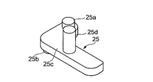
図17に示すように、ストッパ25は、L字形状をなし、一面側に、円柱状の回転軸25a、突起部25dを備え、他面側に同じく円柱状のガイド軸25bを備えている。図13に最も良く示されるように、ストッパ25の一面の回転軸25aは、第2のガイド部76の天井板に設けられた軸孔13に挿入される。また、ストッパーの突起部25dと突起部73との間には、ストッパ25を第2のガイド部76方向へと引っ張るコイルバネ71が設けられている。
As shown in FIG. 17, the
図16(a)及び(b)に示すように、スライドカム22は、長四角板からなり、一角部は切り欠かれるとともに、上方に台形状の上面を備えて突出した台形部22aを備えている。また、長さ方向に沿って長いガイド溝23が設けられている。さらに、スライドカム22の下面中央に下方に突出する突起部22cと、台形部22aとは反対側の端部で、且つ下方に円柱状の突起部22bが設けられている。スライドカム22の長孔23内にストッパ25のガイド軸25bが挿入される。
As shown in FIGS. 16 (a) and 16 (b), the
図11乃至13及び図15に示されるように、第3のガイド部29は第1及び第2のガイド部75,76と一体に構成された板体からなり、中央部にL字形状のガイドのための貫通孔からなるカム溝24を備え、また、前方には、下方に突出した突起部29aを備えている。スライドカム25の突起部22cは、第3のガイド部29のL字状のカム溝24に挿入されている。また、第3のガイド部29の円柱状の突起部29aと、スライドカム22の突起部22bとの間にバネ72が設けられ、スライドカム29を前方に付勢している。
As shown in FIGS. 11 to 13 and FIG. 15, the
このように、2本のコイルバネ71,72によって、嵌合部インシュレータとストッパ、スライドカム等、固定インシュレータは、つりあっており、図示しない相手側コネクタと未嵌合状態では、常に一定の位置にある。
In this way, the fixed insulators such as the fitting portion insulator, the stopper, and the slide cam are balanced by the two
本発明の第2の実施の形態によるフローティングコネクタ103を組み立てるには、図15に示す嵌合部インシュレータ20に、図16に示すスライドカム22と、図17に示すストッパ25を装着した後、コイルバネ71,72を夫々装着し、固定インシュレータ40に後方より装着すれば、図7に示すフローティングコネクタ103の完成となる。
In order to assemble the floating
次に本発明の第2の実施の形態のフローティングコネクタ103の作用について説明する。
Next, the operation of the floating
第2の実施の形態によるフローティングコネクタ103は、嵌合方向を第1の方向(Z軸方向)、幅方向を第3の方向(X軸方向)、上下方向を第2の方向(Y軸方向)とすると、嵌合部インシュレータが固定インシュレータに対して上下方向、即ち、第2の方向に常に可動な状態にある。
In the floating
図7乃至図13に示すように、ストッパ25が固定インシュレータ40の側端面46に当接している状態においては、ストッパ25の一軸は第2のガイド部76の天井面に挿入されているので、嵌合方向である第1の方向には移動しない。また、スライドカム22が両側にあるために、固定インシュレータ40に対して、幅方向である第3の方向にも移動不可能な状態にある。第2の実施の形態によるフローティングコネクタ103を図示しない相手側コネクタに嵌合させると、スライドカム22の前端に相手側コネクタの先端部が当接して、スライドカム22がコイルバネ72の復帰力に抗して後方に押し込まれる。スライドカム22が後方に押し込まれると、図11に示すスライドカム22の下部に突出した突起部22cは、カム溝24を第1の方向に相対移動し、カム溝24のL字の交点まで移動する。この状態においては、スライドカム22は、カム溝24の第3の方向であるコネクタの幅方向に移動可能となり、したがって、嵌合部インシュレータ20は、固定インシュレータ40に対して第3の方向(幅方向)に可動となる。この状態で、固定インシュレータ40を引き抜けば、再び嵌合部インシュレータ20と相手側コネクタとを離脱させることができる。
As shown in FIGS. 7 to 13, when the
また、嵌合状態で、ストッパ25を左回りに回転させてロックを解除すれば、固定インシュレータ40と嵌合部インシュレータ20は、前後方向即ち、第1の方向に可動となる。また、嵌合部インシュレータ20は、ストッパ25の回転の際に、スライドカム22を内側に押し込む力を与え、このストッパ25の位置は、スライドカム22の第2の方向の位置決めするために、スライドカム22の固定インシュレータへの当接位置と、内部に収容された位置を、ストッパ25の回転位置によって決定される。このストッパ位置は、コイルバネ71のバネ力により決定される。
Further, when the lock is released by rotating the
相手側コネクタとの嵌合の際は、そのコイルバネ71の固定力に勝る挿入力により、スライトカムが押されることにより、嵌合インシュレータ20とスライドカム22の間に空間が発生し、第1〜第3の何れかの方向にフローティング可能となる。
When mating with the mating connector, a space is generated between the
このように、本発明の第2の実施の形態によるフローティングコネクタ103において、スライドカム22は相手側コネクタの抜去方向に付勢されながら、嵌合部インシュレータ20に第1の方向に移動可能に固定され、ストッパ25は固定インシュレータ40に固定され、スライドカム22が相手側コネクタの抜去方向に突出状態の時には、ストッパ25の一部が嵌合部インシュレータ20内に入り込み、また、一部は固定インシュレータの側壁部に当接するように外方に露出している。
As described above, in the floating
本発明の第2の実施の形態においては、スライドカム22が相手側コネクタの挿入方向に位置するときには、ストッパ25の一部は、嵌合部インシュレータ20内に入り込んでいる構成であるが、ロックを解除したときに、全部が嵌合部インシュレータ20内に入り込んでいる構成となる。
In the second embodiment of the present invention, when the
また、本発明の第2の実施の形態によるフローティングコネクタ103においては、第3のガイド部29のスライドカム22の突出部のカム溝24をL字形状としたが、R状または円弧状とすることで、嵌合前は、第1及び第3の方向をロックし、嵌合の際、スライドカムを押圧しながら、幅方向の中心寄りに移動させ、このスライドカムの動きによって、ストッパが回転して、第1の方向のロックが解除され、第1の方向及び第3の方向へのフローティングが可能となるように構成することもできる。
In the floating
以上説明したように、本発明に係るフローティングコネクタは、HDDのSATA用コネクタに接続されるコネクタのように、小さく且つ振動を受け易い部位のフローティングコネクタとして最適である。 As described above, the floating connector according to the present invention is optimal as a floating connector that is small and susceptible to vibration, such as a connector connected to the SATA connector of the HDD.
1 コンタクト
1a 接触部
2a 端子部
2 支持部
3 元部
4 先端部
5 折り返し部
6 金属板
7 絶縁体
8 絶縁体の一部
9 絶縁体の保持部
10 コンタクト部
11 本体
12 ガイド部
13 軸孔
15,18 嵌合部
16,17 溝
19 突条部
20 嵌合部インシュレータ
21 突条部
22 スライドカム
22a 台形部
22b 突起部
22c 突起部
23 ガイド溝
24 カム溝
25 ストッパ
25a 回転軸
25b ガイド軸
25c 板体
25d 突起部
29 第3のガイド部
30 可動インシュレータ
31 本体
32 収容部
33 溝
33a 底部
34 フローティング係合片
35 係合溝
40 固定インシュレータ
41 本体
42,43 フローティングガイド片
44,45 段部
47 底板
48 側板
51 スライドインシュレータ
51a 係合部
51b モールドイン部
51c 突出部
52 ベースインシュレータ
52a モールドイン部
52b 底部
53 コンタクト
53a 一端部
53b 挿通部
53c フローティング部
53d 挿通部
53e 他端部
61 相手側インシュレータ
63 相手側コンタクト
75 第1のガイド部
76 第2のガイド部
77 ガイド収容部
73 突起部
71 コイルバネ
72 バネ
101,103,105 フローティングコネクタ
102 相手側コネクタ
DESCRIPTION OF
Claims (6)
前記インシュレータは、前記第1の方向と前記第1の方向と交錯する第2の方向と前記第1及び第2の方向と交錯する第3の方向にフローティング可能な嵌合部インシュレータと、固定インシュレータとを有し、
前記ロック機構は、未嵌合の場合は前記嵌合部インシュレータを前記第1の方向へフローティングすることをロックし、嵌合の際、前記相手側コネクタによって、前記スライドカムが押圧され、前記ストッパが移動する事により、前記嵌合部インシュレータを前記第1の方向へフローティング可能とすることを特徴とするフローティングコネクタ。 In a floating connector having a contact and an insulator for holding the contact, the floating connector is configured to be floatable in a first direction that is a fitting direction with a mating connector, and when not mated with the mating connector , the first connector A locking mechanism that is configured not to float in the direction of 1 and includes a slide cam and a stopper for floating and fixing in the first direction;
The insulator includes: a fitting insulator that can float in the first direction, a second direction that intersects the first direction, and a third direction that intersects the first and second directions; and a fixed insulator And
The locking mechanism locks the floating of the fitting part insulator in the first direction when not fitted, and the sliding cam is pressed by the mating connector during fitting, and the stopper The floating connector allows the fitting part insulator to float in the first direction by moving .
前記第1の方向へのフローティング固定の為のスライドカムとストッパとを備えたロック機構を備え、 A lock mechanism including a slide cam and a stopper for floating fixation in the first direction;
前記インシュレータは、前記第1の方向にフローティング可能な嵌合部インシュレータと、前記第1の方向と交錯する第2の方向と前記第1及び第2の方向と交錯する第3の方向にフローティング可能な可動インシュレータと、固定インシュレータとを有し、 The insulator can float in a third direction intersecting the first direction and the second direction intersecting with the first direction, the fitting part insulator capable of floating in the first direction, and the second direction intersecting with the first direction. A movable insulator and a fixed insulator,
前記ロック機構は、未嵌合の場合は前記嵌合部インシュレータを前記第1の方向へフローティングすることをロックし、嵌合の際、前記相手側コネクタによって、前記スライドカムが押圧され、前記ストッパが移動する事により、前記嵌合部インシュレータを前記第1の方向へフローティング可能とすることを特徴とするフローティングコネクタ。 The locking mechanism locks the floating of the fitting part insulator in the first direction when not fitted, and the sliding cam is pressed by the mating connector during fitting, and the stopper The floating connector allows the fitting part insulator to float in the first direction by moving.
Priority Applications (5)
| Application Number | Priority Date | Filing Date | Title |
|---|---|---|---|
| JP2004319357A JP4086245B2 (en) | 2004-07-20 | 2004-11-02 | Floating connector |
| EP05254483A EP1667287B1 (en) | 2004-07-20 | 2005-07-19 | Connector in which floating of a fitting portion is controlled by fitting of a mating connector |
| US11/184,501 US7204707B2 (en) | 2004-07-20 | 2005-07-19 | Connector in which floating of a front portion is controlled by fitting of a mating connector |
| KR1020050065260A KR100800213B1 (en) | 2004-07-20 | 2005-07-19 | Connector which adjusts floating part by fitting with mating connector |
| TW094124449A TWI303903B (en) | 2004-07-20 | 2005-07-20 | Connector in which floating of a fitting portion is controlled by fitting of a mating connector |
Applications Claiming Priority (2)
| Application Number | Priority Date | Filing Date | Title |
|---|---|---|---|
| JP2004211859 | 2004-07-20 | ||
| JP2004319357A JP4086245B2 (en) | 2004-07-20 | 2004-11-02 | Floating connector |
Publications (2)
| Publication Number | Publication Date |
|---|---|
| JP2006059788A JP2006059788A (en) | 2006-03-02 |
| JP4086245B2 true JP4086245B2 (en) | 2008-05-14 |
Family
ID=35657821
Family Applications (1)
| Application Number | Title | Priority Date | Filing Date |
|---|---|---|---|
| JP2004319357A Expired - Fee Related JP4086245B2 (en) | 2004-07-20 | 2004-11-02 | Floating connector |
Country Status (5)
| Country | Link |
|---|---|
| US (1) | US7204707B2 (en) |
| EP (1) | EP1667287B1 (en) |
| JP (1) | JP4086245B2 (en) |
| KR (1) | KR100800213B1 (en) |
| TW (1) | TWI303903B (en) |
Families Citing this family (12)
| Publication number | Priority date | Publication date | Assignee | Title |
|---|---|---|---|---|
| US7375960B2 (en) * | 2005-05-06 | 2008-05-20 | Silicon Image, Inc. | Apparatus for removably securing storage components in an enclosure |
| TWM300879U (en) * | 2005-12-26 | 2006-11-11 | Hon Hai Prec Ind Co Ltd | Electrical connector |
| TWI318483B (en) | 2006-04-28 | 2009-12-11 | I Pex Co Ltd | Electrical connector |
| JP4545176B2 (en) * | 2007-06-29 | 2010-09-15 | 日本航空電子工業株式会社 | connector |
| JP4439557B2 (en) * | 2007-11-22 | 2010-03-24 | 日本航空電子工業株式会社 | connector |
| US7530839B1 (en) * | 2008-04-15 | 2009-05-12 | Jess-Link Products Co., Ltd. | Electrical connector |
| US8210861B2 (en) | 2010-05-12 | 2012-07-03 | Tyco Electronics Corporation | Connector assembly having two connectors capable of movement in differing directions |
| JP5587807B2 (en) * | 2011-02-07 | 2014-09-10 | ケル株式会社 | Floating connector |
| JP6095167B2 (en) * | 2013-06-12 | 2017-03-15 | イリソ電子工業株式会社 | connector |
| DE102016205476B4 (en) * | 2016-04-01 | 2019-08-01 | Continental Automotive Gmbh | Plug receptacle and plug for an electrical plug connection and electrical plug connection |
| CN111164787B (en) * | 2017-12-28 | 2023-03-31 | 远景Aesc 日本有限公司 | Battery system and holder |
| CN111630724B (en) | 2018-01-24 | 2022-05-27 | 松下知识产权经营株式会社 | Electronic device |
Family Cites Families (6)
| Publication number | Priority date | Publication date | Assignee | Title |
|---|---|---|---|---|
| FR2716299B1 (en) * | 1994-02-16 | 1996-04-19 | Framatome Connectors France | Temporary locking floating connector and its application to the space sector. |
| JPH10321290A (en) | 1997-05-15 | 1998-12-04 | Japan Aviation Electron Ind Ltd | Surface mount connector |
| JP3276324B2 (en) * | 1997-08-08 | 2002-04-22 | 矢崎総業株式会社 | Connector fitting structure |
| JP3866893B2 (en) | 2000-02-29 | 2007-01-10 | ヒロセ電機株式会社 | Floating connector and connector device using the floating connector |
| US6364536B1 (en) * | 2000-03-30 | 2002-04-02 | Wenzong Chen | Floating connector assembly |
| JP2002093531A (en) | 2000-09-11 | 2002-03-29 | Yazaki Corp | Self-aligning electrical connector |
-
2004
- 2004-11-02 JP JP2004319357A patent/JP4086245B2/en not_active Expired - Fee Related
-
2005
- 2005-07-19 KR KR1020050065260A patent/KR100800213B1/en not_active IP Right Cessation
- 2005-07-19 EP EP05254483A patent/EP1667287B1/en not_active Not-in-force
- 2005-07-19 US US11/184,501 patent/US7204707B2/en not_active Expired - Fee Related
- 2005-07-20 TW TW094124449A patent/TWI303903B/en not_active IP Right Cessation
Also Published As
| Publication number | Publication date |
|---|---|
| EP1667287A3 (en) | 2007-05-09 |
| EP1667287A2 (en) | 2006-06-07 |
| KR100800213B1 (en) | 2008-02-01 |
| US20060019520A1 (en) | 2006-01-26 |
| KR20060053899A (en) | 2006-05-22 |
| TW200618416A (en) | 2006-06-01 |
| US7204707B2 (en) | 2007-04-17 |
| TWI303903B (en) | 2008-12-01 |
| EP1667287B1 (en) | 2012-07-04 |
| JP2006059788A (en) | 2006-03-02 |
Similar Documents
| Publication | Publication Date | Title |
|---|---|---|
| JP4086245B2 (en) | Floating connector | |
| JP5059571B2 (en) | Female terminal bracket for PCB | |
| JP2001351735A (en) | Card connector | |
| CN103427184B (en) | Electric connector | |
| JP2000208183A (en) | Card edge connector | |
| JP2002008760A (en) | connector | |
| JPH1055856A (en) | Floating electrical connector | |
| JP2004235142A (en) | Latch for card edge connector | |
| JPH0216542Y2 (en) | ||
| JP6016661B2 (en) | connector | |
| JP5587807B2 (en) | Floating connector | |
| JP2002289298A (en) | Movable connector assembly | |
| JP2002075530A (en) | Connector support mechanism | |
| WO2018012243A1 (en) | Connector | |
| JP2008276987A (en) | Contact and electrical connector | |
| JP7068252B2 (en) | Electrical junction box unit | |
| JP3451206B2 (en) | Board connector | |
| WO2005099046A1 (en) | Connector | |
| JPH08250211A (en) | Edge connector | |
| JP7051759B2 (en) | Electronic unit | |
| JP2005228731A (en) | Electric connection device | |
| JP5909410B2 (en) | Flat circuit body connector connection structure | |
| CN100521390C (en) | Connector in which floating of a fitting portion is controlled by fitting of a mating connector | |
| JP2002134195A (en) | Flexible circuit board connector | |
| JP7454344B2 (en) | Fitting structure between right angle connector and connection target and fitting method between right angle connector and connection target |
Legal Events
| Date | Code | Title | Description |
|---|---|---|---|
| A977 | Report on retrieval |
Free format text: JAPANESE INTERMEDIATE CODE: A971007 Effective date: 20070823 |
|
| A131 | Notification of reasons for refusal |
Free format text: JAPANESE INTERMEDIATE CODE: A131 Effective date: 20070829 |
|
| A521 | Request for written amendment filed |
Free format text: JAPANESE INTERMEDIATE CODE: A523 Effective date: 20071029 |
|
| TRDD | Decision of grant or rejection written | ||
| A01 | Written decision to grant a patent or to grant a registration (utility model) |
Free format text: JAPANESE INTERMEDIATE CODE: A01 Effective date: 20080213 |
|
| A61 | First payment of annual fees (during grant procedure) |
Free format text: JAPANESE INTERMEDIATE CODE: A61 Effective date: 20080215 |
|
| FPAY | Renewal fee payment (event date is renewal date of database) |
Free format text: PAYMENT UNTIL: 20110228 Year of fee payment: 3 |
|
| R150 | Certificate of patent or registration of utility model |
Free format text: JAPANESE INTERMEDIATE CODE: R150 |
|
| FPAY | Renewal fee payment (event date is renewal date of database) |
Free format text: PAYMENT UNTIL: 20110228 Year of fee payment: 3 |
|
| S111 | Request for change of ownership or part of ownership |
Free format text: JAPANESE INTERMEDIATE CODE: R313117 |
|
| FPAY | Renewal fee payment (event date is renewal date of database) |
Free format text: PAYMENT UNTIL: 20110228 Year of fee payment: 3 |
|
| R350 | Written notification of registration of transfer |
Free format text: JAPANESE INTERMEDIATE CODE: R350 |
|
| FPAY | Renewal fee payment (event date is renewal date of database) |
Free format text: PAYMENT UNTIL: 20110228 Year of fee payment: 3 |
|
| FPAY | Renewal fee payment (event date is renewal date of database) |
Free format text: PAYMENT UNTIL: 20110228 Year of fee payment: 3 |
|
| FPAY | Renewal fee payment (event date is renewal date of database) |
Free format text: PAYMENT UNTIL: 20120229 Year of fee payment: 4 |
|
| FPAY | Renewal fee payment (event date is renewal date of database) |
Free format text: PAYMENT UNTIL: 20120229 Year of fee payment: 4 |
|
| FPAY | Renewal fee payment (event date is renewal date of database) |
Free format text: PAYMENT UNTIL: 20120229 Year of fee payment: 4 |
|
| FPAY | Renewal fee payment (event date is renewal date of database) |
Free format text: PAYMENT UNTIL: 20130228 Year of fee payment: 5 |
|
| FPAY | Renewal fee payment (event date is renewal date of database) |
Free format text: PAYMENT UNTIL: 20130228 Year of fee payment: 5 |
|
| FPAY | Renewal fee payment (event date is renewal date of database) |
Free format text: PAYMENT UNTIL: 20130228 Year of fee payment: 5 |
|
| FPAY | Renewal fee payment (event date is renewal date of database) |
Free format text: PAYMENT UNTIL: 20140228 Year of fee payment: 6 |
|
| R250 | Receipt of annual fees |
Free format text: JAPANESE INTERMEDIATE CODE: R250 |
|
| R250 | Receipt of annual fees |
Free format text: JAPANESE INTERMEDIATE CODE: R250 |
|
| LAPS | Cancellation because of no payment of annual fees |