JP4076248B2 - Color reproduction device - Google Patents
Color reproduction device Download PDFInfo
- Publication number
- JP4076248B2 JP4076248B2 JP24363497A JP24363497A JP4076248B2 JP 4076248 B2 JP4076248 B2 JP 4076248B2 JP 24363497 A JP24363497 A JP 24363497A JP 24363497 A JP24363497 A JP 24363497A JP 4076248 B2 JP4076248 B2 JP 4076248B2
- Authority
- JP
- Japan
- Prior art keywords
- image
- input
- profile
- color
- output
- Prior art date
- Legal status (The legal status is an assumption and is not a legal conclusion. Google has not performed a legal analysis and makes no representation as to the accuracy of the status listed.)
- Expired - Fee Related
Links
- 238000005286 illumination Methods 0.000 claims description 218
- 238000012937 correction Methods 0.000 claims description 148
- 238000006243 chemical reaction Methods 0.000 claims description 88
- 238000000034 method Methods 0.000 claims description 79
- 230000003595 spectral effect Effects 0.000 claims description 59
- 230000008569 process Effects 0.000 claims description 56
- 238000001514 detection method Methods 0.000 claims description 44
- 238000003384 imaging method Methods 0.000 claims description 37
- 238000001228 spectrum Methods 0.000 claims description 37
- 238000007781 pre-processing Methods 0.000 claims description 30
- 238000012545 processing Methods 0.000 claims description 29
- 239000011159 matrix material Substances 0.000 claims description 26
- 230000009471 action Effects 0.000 claims description 20
- 238000004364 calculation method Methods 0.000 claims description 19
- 238000005259 measurement Methods 0.000 claims description 14
- 238000012805 post-processing Methods 0.000 claims description 9
- 230000001678 irradiating effect Effects 0.000 claims 1
- 238000002360 preparation method Methods 0.000 claims 1
- 238000010586 diagram Methods 0.000 description 37
- 230000000694 effects Effects 0.000 description 16
- 230000008859 change Effects 0.000 description 8
- 230000007613 environmental effect Effects 0.000 description 7
- 230000006870 function Effects 0.000 description 7
- 238000012986 modification Methods 0.000 description 7
- 230000004048 modification Effects 0.000 description 7
- OAICVXFJPJFONN-UHFFFAOYSA-N Phosphorus Chemical compound [P] OAICVXFJPJFONN-UHFFFAOYSA-N 0.000 description 6
- 230000003287 optical effect Effects 0.000 description 5
- 230000007274 generation of a signal involved in cell-cell signaling Effects 0.000 description 3
- 238000009434 installation Methods 0.000 description 3
- 239000004973 liquid crystal related substance Substances 0.000 description 3
- 239000003086 colorant Substances 0.000 description 2
- 238000012790 confirmation Methods 0.000 description 2
- 239000002537 cosmetic Substances 0.000 description 2
- 238000005516 engineering process Methods 0.000 description 2
- 238000011156 evaluation Methods 0.000 description 2
- 238000010422 painting Methods 0.000 description 2
- 230000005540 biological transmission Effects 0.000 description 1
- 238000007796 conventional method Methods 0.000 description 1
- 238000013500 data storage Methods 0.000 description 1
- 238000013461 design Methods 0.000 description 1
- 238000007726 management method Methods 0.000 description 1
- 239000000463 material Substances 0.000 description 1
- 230000002093 peripheral effect Effects 0.000 description 1
- 238000002310 reflectometry Methods 0.000 description 1
- 230000001172 regenerating effect Effects 0.000 description 1
- 230000035945 sensitivity Effects 0.000 description 1
- 230000009466 transformation Effects 0.000 description 1
Images


Classifications
-
- H—ELECTRICITY
- H04—ELECTRIC COMMUNICATION TECHNIQUE
- H04N—PICTORIAL COMMUNICATION, e.g. TELEVISION
- H04N1/00—Scanning, transmission or reproduction of documents or the like, e.g. facsimile transmission; Details thereof
- H04N1/46—Colour picture communication systems
- H04N1/56—Processing of colour picture signals
- H04N1/60—Colour correction or control
- H04N1/6083—Colour correction or control controlled by factors external to the apparatus
- H04N1/6086—Colour correction or control controlled by factors external to the apparatus by scene illuminant, i.e. conditions at the time of picture capture, e.g. flash, optical filter used, evening, cloud, daylight, artificial lighting, white point measurement, colour temperature
-
- H—ELECTRICITY
- H04—ELECTRIC COMMUNICATION TECHNIQUE
- H04N—PICTORIAL COMMUNICATION, e.g. TELEVISION
- H04N1/00—Scanning, transmission or reproduction of documents or the like, e.g. facsimile transmission; Details thereof
- H04N1/46—Colour picture communication systems
- H04N1/56—Processing of colour picture signals
- H04N1/60—Colour correction or control
- H04N1/603—Colour correction or control controlled by characteristics of the picture signal generator or the picture reproducer
-
- H—ELECTRICITY
- H04—ELECTRIC COMMUNICATION TECHNIQUE
- H04N—PICTORIAL COMMUNICATION, e.g. TELEVISION
- H04N1/00—Scanning, transmission or reproduction of documents or the like, e.g. facsimile transmission; Details thereof
- H04N1/46—Colour picture communication systems
- H04N1/56—Processing of colour picture signals
- H04N1/60—Colour correction or control
- H04N1/6083—Colour correction or control controlled by factors external to the apparatus
- H04N1/6088—Colour correction or control controlled by factors external to the apparatus by viewing conditions, i.e. conditions at picture output
Landscapes
- Engineering & Computer Science (AREA)
- Multimedia (AREA)
- Signal Processing (AREA)
- Color Image Communication Systems (AREA)
- Facsimile Image Signal Circuits (AREA)
- Image Processing (AREA)
- Processing Of Color Television Signals (AREA)
- Controls And Circuits For Display Device (AREA)
Description
【0001】
【発明の属する技術分野】
本発明は、画像入力装置で撮影された対象物の画像の色を正確に出力装置に出力する色再現装置に関する。
【0002】
【従来の技術】
従来から印刷物やTVモニタに表示させる色を人間が視覚で認識した色に少しでも近づけるようにするために様々な試みが行われてきている。
【0003】
近年のコンピュータの高性能化、小型化や、DTPシステム(デスクトップパブリッシング、電子出版)が普及するに伴い、TVモニタに表示させる表示色と入出力対象である印刷物の色を合わせる色合わせ技術(例えば、特開平5−216452号公報や特開平6−51732号公報等)が提案されている。
【0004】
この色合わせ技術を代表するCMS(カラーマネージメントシステム)では、例えば、図32,33に示すような画像入力装置1及び画像出力装置2の間に色補正部3を設けて、画像入力側(撮影側)、画像出力側(観察側)でそれぞれ入力プロファイル4、出力プロファイル5を持ち、一度、画像入力装置1及び画像出力装置2に依存しない色(以後、デバイスインデペンデントカラーと呼ぶ)に変換した後、入出力の色合わせを行っている。
【0005】
また、特開平9−172649号公報では、図34に示すような、再生される場所とは、異なる遠隔の場所等で撮影した画像を伝送し、スペクトルで色合わせを行い、正確な色再現で再生(表示、印刷)するカラー画像記録再生システムが提案されている。
【0006】
これは、撮影側で対象物のマルチスペクトル画像を撮影し、撮影側の照明スペクトルデータと、再生側の照明スペクトルデータを用いて、再生側の照明光下で対象物を撮影したのと同一のスペクトル画像に変換する。
【0007】
次に、多次元のスペクトル画像をXYZ値等の3次元のベクトル画像へ変換し、再生側に伝送する。そして、再生側で再生装置の分光特性に応じたカラー信号に変換し、出力する。
【0008】
また、色補正した画像は、出力媒体(この図ではモニタ)に合わせた色に補正して出力画像を出力するが出力プロファイルは次のような手順で作成される。
【0009】
モニタ131及び測定に用いる色度計132は、暗室等外光の影響を受けない場所においてセッティングされ、図35に示すようにRGB信号生成部133により所定のRGB信号を生成して、画像表示制御部134を介してモニタ131に表示される。このモニタ131に表示される色は、色度計132で測定される。
【0010】
この色度計132から出力される信号は、色度検出部135によりXYZ値等の色度値として検出され、出力プロファイル演算部136に送られる。
【0011】
出力プロファイル演算部136では、RGB信号生成部133で生成されるRGB値と色度検出部135で検出される色度値との関係から出力プロファイルを演算する。次に、モニタ131に出力するRGB値とモニタ131から出力されるXYZ値の関係について説明する。
【0012】
モニタ131はRGB蛍光体を有しており、このRGB蛍光体に信号を送りカラー画像を表示する。RGB蛍光体へ送る信号値(RGB値)は、図35に示すRGB信号生成部133で生成される。
【0013】
RGB値はモニタ131のγ特性により非線型に変換される。RGBのγ特性をそれぞれγr[]、γg[] 、γb[] とする。さらに、RGB蛍光体各々の和が色として感じられるため、γ特性を受けた信号値が加算されたものが、モニタから出力される次式(11)で示すような色度値(XYZ値)となる。
【0014】
【数1】

ここで、Xrmax、Yrmax、Zrmaxは、R蛍光体の最大輝度時のXYZ値であり、Xgmax、Ygmax、Zgmaxは、G蛍光体の最大輝度時のXYZ値であり、Xbmax、Ybmax、Zbmaxは、B蛍光体の最大輝度時のXYZ値である。
【0016】
所望するXYZ値を得るためのRGB値は、式 (11)を利用して演算でき、次の式(12)のようになる。
【0017】
【数2】
つまり、マトリックス変換とγ補正により構成される。一連の処理をまとめたものを図36に示す。
【0019】
この構成において、出力プロファイル演算部136では、RGB値とXYZ値からマトリックス変換のためのマトリックス係数とγ補正のためのγ補正値を演算し、出力プロファイル記憶部137に記憶する。そしてデバイス値変換部138では、マトリックス係数とγ補正値を利用して、マトリックス変換及びγ補正を行い、画像表示制御部134のモニタに表示すべきRGB値を出力する。
【0020】
【発明が解決しようとする課題】
前述した従来のCMS(図32,33)では入力側、出力側ともに光源がD50に指定されている。そのため、D50でない照明光下で画像が撮影された場合や、D50でない照明下で出力された画像を観察した場合、色が合わない問題が生じる。
【0021】
図34に示した従来のカラー画像記録再生システムにおいては、撮影側で測定された画像を観測側の照明光にあわせたXYZ値等の色度値に変換し、観察側に伝送することを想定している。
【0022】
しかし、一度XYZ値に変換された画像は、既にスペクトル情報を持たないため、観察側では再度、自由に照明光のデータ変換できない。また、撮影時の照明光のスペクトルデータと、観察時の観察光のスペクトルデータのみを用いて、スペクトルで色合わせをしているため、色再現の精度をあげるためには、入力画像自体がある程度多くのスペクトル情報を必要とする。
【0023】
そのため、画像入力装置は、多くのバンドでスペクトル画像を撮影できるマルチスペクトルカメラでなければならず、ワンショットで撮影することが難しくなる。また画像のデータ量も大きいものになってしまう。
【0024】
そして、色補正した画像をモニタに映し出す際には、モニタのオフセット光や外光が影響して、従来手法でモニタへの出力プロファイルを作成しても、必ずしも満足する色再現は得られなかった。
【0025】
通常、モニタに電源を入れると、モニタのオフセット光の影響で、モニタへR=G=B=0を出力してもモニタ面が黒(X=Y=Z=0)にはならない。また、モニタが置かれている場所の照明光(外光)がモニタ管面を照射しており、このモニタ管面から反射により、モニタに電源を入れなくてもX=Y=Z=0にはならない。つまり、モニタのオフセット光や外光は、モニタに本来表示される画像信号に加算されることとなる。モニタのオフセット光と外光を加算したものを以後、バイアス値と称する。
【0026】
このバイアス値が加算された状態を考慮して、プロファイルを作成すれば正確な色再現ができるが、オフセット光や外光は、時間と共に大きく変動する。例えば、モニタは電源を入れてから安定するまでにオフセット光が大きく変化する。また、外光として用いている照明光源が変わったり、経時変化したり、さらに窓の外の屋外光が変化したりして大きく変化する。これらのオフセット光や外光が変動する度に出力プロファイルを生成し直すには、専門の知識を要するとともに、多大の時間も必要となる。
【0027】
そこで本発明は、画像入力装置の情報と、撮影時及び観察時の照明光のスペクトルデータの情報及び撮影した対象物のスペクトルの統計的性質等の情報からなる色再現環境情報とを参照した画像変換を行い、画像の撮影場所と再現場所の遠隔化も可能で、オフセット光や撮影場所の外光が変動した場合にも容易で高速に出力プロファイルを作用させた正確な色再現が可能な色再現装置、色補正装置、色再現方法、及び色再現プログラムを提供することを目的とする。
【0028】
【課題を解決するための手段】
本発明は上記目的を達成するために、撮影された被写体となるべき対象物の画像である入力画像の色変換を行う色補正手段を備える色再現装置において、上記色補正手段は、上記入力画像を撮影した画像入力装置の撮影特性と、上記入力画像を撮影する時の照明光のスペクトルデータである撮影照明光データと、を用いて入力プロファイルを算出する入力プロファイル作成部と、上記入力プロファイルを参照して、上記入力画像をデバイスインデペンデントカラー画像に変換する入力プロファイル作用部と、を備える色再現装置を提供する。また、撮影された被写体となるべき対象物の画像である入力画像の色変換を行う色補正装置であって、上記入力画像を撮影した画像入力装置の撮影特性と、上記入力画像を撮影する時の照明光のスペクトルデータである撮影照明光データと、を用いて入力プロファイルを算出する入力プロファイル作成部と、上記入力プロファイルを参照して、上記入力画像をデバイスインデペンデントカラー画像に変換する入力プロファイル作用部と、を備える色補正装置を提供する。
【0029】
さらに、撮影された被写体となるべき対象物の画像である入力画像の色変換を行う色補正過程を備える色再現方法において、上記色補正過程は、上記入力画像を撮影した画像入力手段の撮影特性と、上記入力画像を撮影する時の照明光のスペクトルデータである撮影照明光データと、を用いて入力プロファイルを算出する入力プロファイル作成過程と、上記入力プロファイルを参照して、上記入力画像をデバイスインデペンデントカラー画像に変換する入力プロファイル作用過程と、を備える色再現方法を提供する。
【0030】
また、撮影された被写体となるべき対象物の画像である入力画像の色変換を行う色補正処理をコンピュータに実行させるための色再現プログラムにおいて、上記色補正処理は、上記入力画像を撮影した画像入力手段の撮影特性と、上記入力画像を撮影する時の照明光のスペクトルデータである撮影照明光データと、を用いて入力プロファイルを算出する入力プロファイル作成処理と、上記入力プロファイルを参照して、上記入力画像をデバイスインデペンデントカラー画像に変換する入力プロファイル作用処理と、を備える色再現プログラムを提供する。
【0031】
【発明の実施の形態】
以下、図面を参照して本発明の実施形態について詳細に説明する。
【0032】
図1乃至図7を参照して、本発明による色再現装置の第1の実施形態について説明する。
【0033】
まず図1に示すように、大別して、対象物の画像を撮影する画像入力装置1と、画像の色を補正する色補正部3と、出力画像を出力(表示、印刷)する画像出力装置2とから構成される。
【0034】
この色補正部3は、入力された画像の色を入力プロファイル4aを参照しながらデバイスインデペンデントカラーに変換するデバイスインデペンデントカラー変換部4と、変換されたデバイスインデペンデントカラー画像を出力プロファイル5aを参照しながら画像出力装置2の特性にあわせたデバイス値に変換し画像を出力するデバイス値変換部5とで構成される。
【0035】
上記デバイスインデペンデントカラー変換部4は、図2に示すように、入力される画像入力装置情報と、色再現環境に関する環境情報に応じて入力プロファイル4aを算出する入力プロファイル作成部6と、入力画像に入力プロファイルを作用し色変換を行う入力プロファイル作用部7とで構成される。また図4に示すように、入力プロファイル作成部6は、マトリックス作成部9であり、入力プロファイル作用部7は、マトリックス演算部8としても構成することができる。
【0036】
このように、マトリックス演算で入力プロファイルを作用することができるので、高速に入力画像をデバイスインデペンデントカラー画像に変換することができる。
【0037】
さらに色補正部3としては、図3に示すような、入力プロファイル作成部6で作成した入力プロファイル4aと、画像出力装置情報に基づき出力プロファイル作成部10により作成された出力プロファイル5aとにより、入出力プロファイル12を作成する入出力プロファイル作成部11及び入出力プロファイル作用部13を備えて、入力プロファイルと出力プロファイルを連結して、高速化を実現する構成も考えられる。
【0038】
前述した入力プロファイル作成部6は、色再現画像を作成する様々な情報を考慮して入力プロファイルを作成する為、精度良く、入力画像をデバイスインデペンデントカラー画像に変換できる。
【0039】
図2に示した上記画像入力装置情報は、撮影に用いた画像入力装置の特性やそれらの設定状態(以後、撮影特性と称する)等であり、一方、環境情報は、対象物の画像を画像入力装置で撮影する時の照明光のスペクトルデータ(以後、撮影照明光データと称する)と、撮影した対象物の画像を観察したい場所の照明光のスペクトルデータ(以後、観察照明光データと称する)と、撮影した対象物のスペクトルの統計的性質等の情報(以後、被写体特性と称する)からなる。
【0040】
この撮影特性を用いることによって、画像入力装置それぞれに対し、精度よく色再現画像を推定できる。画像入力装置が複数のスペクトル画像を撮影するマルチスペクトルカメラの場合やデジタルカメラで撮影する場合でも色再現を可能とする。
【0041】
そして撮影照明光データを用いることによって、撮影時の照明光による影響をキャンセルできる。つまり、どんな照明光下(例えば、蛍光燈、白熱灯、太陽など)で対象物を撮影しても対象物自体の正確な分光反射率を算出することができる。また観察照明光データを用いることによって、実際に画像を観察したい場所の照明下の色を算出できる。被写体特性を用いることによって、入力画像が少ないスペクトル情報しか持たなくても、精度良く色再現画像を推定できる。
【0042】
次に図5及び図6を参照して、補正部3に入力される環境情報について説明する。
【0043】
この環境情報は、画像入力装置1、専用の入力装置14、ネットワーク15或いは、記憶媒体16のいずれから供給される。
【0044】
環境情報を画像入力装置1やその他の入力装置から得る場合、画像を撮影した時の環境情報をリアルタイムに得ることができ、環境が刻々と変化する場合でも精度よくデバイスインデペンデントカラー画像に変換できる入力プロファイルを作成できる。
【0045】
また環境情報をネットワーク15若しくは記憶媒体16から得る場合には、遠隔地の環境にあわせて、或いは過去の環境にあわせて、入力プロファイルを作成することもできる。
【0046】
この色補正部3は、大きくは、図2に示すように、デバイスインデペンデントカラー変換部4とデバイス値変換部5とで構成される。デバイスインデペンデントカラー変換部4の入力プロファイル作成部6は、入力装置14等から画像入力装置情報や環境情報が入力される照明光データ選択部18、被写体特性選択部19、及び撮影特性選択部20と、それぞれの出力に基づき入力プロファイル4aを算出する入力プロファイル算出部21とで構成される。また、入力プロファイル作用部7は、入力された画像に対して、選択を行う入力画像選択部22と選択された画像を入力プロファイルに基づき色変換してデバイスインデペンデントカラー画像に処理する色変換部23とで構成される。
【0047】
また、デバイス値変換部5の出力プロファイル作用部24は、デバイスインデペンデントカラー画像を出力プロファイル5aに基づき色変換して再生する色変換部25と、再生された画像の出力先を選択して、画像出力装置17、記憶媒体16或いはネットワーク15に出力する画像出力先選択部26とで構成される。出力プロファイル5aを作成する出力プロファイル作成部10は、画像出力装置情報から必要な情報を選択する出力デバイス特性選択部27と、選択された出力デバイス特性に基づき出力プロファイル5aを算出する出力プロファイル算出部28とで構成される。なお、本実施形態の各構成は、当然、各種の変形、変更が可能である。
【0048】
例えば、画像入力装置1は、複数枚のバンドパスフィルタを用いたマルチスペクトルカメラ、液晶を用いた波長可変フィルタを用いたマルチスペクトルカメラ、プリズム等で光路分割したマルチスペクトルカメラ或いは、デジタルカメラであっても良い。また画像出力装置17は、モニタ、プロジェクタ或いは、プリンタでも良い。
【0049】
また入力装置14は、スペクトルデータを得る場合、分光器やマルチスペクトルカメラを用いることもできる。ネットワーク15の遠隔地に本システムと同じシステムを設置し、相互に画像や環境情報のデータを伝送してもよい。記憶媒体にはフロッピーディスクやMO等を用いる。
【0050】
このような構成において、図7に示すように、色補正部3を前処理の色補正部3aと後処理の色補正部3bとに分けて、色変換部23でデバイスインデペンデントカラー画像にした後、画像出力先選択部31により出力先を選択し、記憶媒体29に保存して移動、或いはネットワーク30を用いて伝送してもよい。
【0051】
また、出力プロファイル作用部24に送られてきたデバイスインデペンデントカラー画像はデバイスインデペンデントカラー画像選択部32で選択され、この選択された画像が出力プロファイル5aに基づき色変換部25で再生される。
【0052】
この実施形態において、デバイスインデペンデントカラー画像の方が、照明変換できるフォーマットの画像よりデータサイズが小さくてすむため、画像データを保存したり伝送する時、有効な場合もある。
【0053】
この構成において、図6に示した構成部位と同等の部位には、同じ参照符号を付して、その説明を省略する。
【0054】
次に、入力プロファイル4aと出力プロファイル5aを連結させた入出力プロファイル12を作成して利用する構成を図8及び、図3を参照して説明する。
【0055】
この色補正部3の入出力プロファイル作用部13は、入力された画像を選択する入力画像選択部33と、作成された入出力プロファイル12に基づき、選択された画像を変換する入力画像変換部34とで構成され、ここで変換された画像は画像出力先選択部35により出力先が選択されて出力される。
【0056】
このような構成により、入力画像の変換が1回ですむため、図6に示した構成に対して、さらに処理が高速化される。
【0057】
図9には、第1の実施形態としての色再現装置を実際に構築した場合の具体的な構成例を示し説明する。本実施形態は、コンピュータのソフトウェア上に構築されたものであり、色再現画像を作成し、モニタに表示するシステムの一例である。
【0058】
図9に示すように、対象物53のマルチスペクトル画像を撮影するマルチスペクトルカメラ41と、撮影時や観察時の照明光データを測定する分光計42,43と、モニタ44のプロファイルを測定する色度計45、コンピュータ46とモニタ44とで構成される。
【0059】
このコンピュータ46でソフトウェア上に構築され前述したように機能する各構成部位において、図6で説明したものと同等に機能する部位には、同じ参照符号を付して、その説明は省略する。
【0060】
このコンピュータ46には、入力プロファイル及び出力プロファイルを作成するための部位(ソフトウェア)の他に、マルチスペクトルカメラ41からの撮影画像を取り込むマルチスペクトル画像撮影部47と、入力プロファイル4aを作成するための照明光データを得るために分光計42,43を制御する照明光データ測定部48と、出力プロファイル5aを作成するためのモニタ44のデータを得るために色度計45を制御するモニタ測定部49と、色が再現された画像をモニタ44に表示させるための色再現画像表示部50とを備える。
【0061】
このような構成においては、色再現画像作成処理を行う前に、入力プロファイル及び、出力プロファイルを作成する必要がある。
【0062】
入力プロファイルの作成には、撮影時や観察時の照明光のスペクトルデータを分光計42,43を用いて測定する。測定に用いる参照板51,52は、照明光のスペクトルデータを測定できれば良いので、分光反射率が既知のものを用いれば良い。標準白色版等の反射率が高く、経時変化の少ないものが好ましい。撮影照明光に電球タイプ、観察照明光に蛍光燈タイプの照明が図示されているが、同じ照明としても勿論よい。尚、人工照明光ではなく自然の太陽光を用いて測定しても良い。
【0063】
照明光データ測定部48で測定した照明光データから算出したマルチスペクトルカメラ41の撮影特性や、対象物の特性を別途入力して、入力プロファイル作成部6で入力プロファイル4aを作成する。作成された入力プロファイル4aは、図示しないメモリ上に格納しても、ディスク上に保存してもよく、使用時に再度読み込めば良い。
【0064】
そして出力プロファイル5aは、モニタ44に適当な色を表示し、これを色度計45で測定した測定値を用いることで作成できる。具体的には、モニタ44の発光体の色度値と、モニタ44に入力するRGBのデジタル値と実際に発光される輝度との関係(一般的にγ特性として知られる)を算出すればよい。
【0065】
モニタ測定部49で測定したデータに基づき、出力プロファイル作成部10で出力プロファイル5aを作成する。作成された出力プロファイル5aは、入力プロファイル4aと同様に、メモリ上やディスク上に保存して使用時に再度読み込んでも良い。
【0066】
本実施形態では、モニタ測定として別途、色度計を備えたが照明光データ測定に用いる分光計を兼用することも可能である。
【0067】
そして測定対象物の色再現画像を作成するには、マルチスペクトルカメラ41で測定対象物53を測定し、入力プロファイル4a、出力プロファイル5aを順に作用させて、画像を出力するモニタ44の特性にあわせて、画像を作成する。マルチスペクトルカメラ41は、バンドパスフィルタを複数枚で構成される回転色フィルタを持つマルチスペクトルカメラでも、透過波長可変フィルタを用いたマルチスペクトルカメラでも構わない。
【0068】
また、入力プロファイル4aを3次元のデータ用として作成しておけば、通常のRGBカメラや、デジタルカメラを用いることもできる。
【0069】
本実施形態は、1 台のパーソナルコンピュータで色再現装置を実現しているが、ネットワークに接続された複数のパーソナルコンピュータ間で正確に色を伝える色再現装置も実現できる。
【0070】
以下に、ソフトウェア処理のアルゴリズムの例について説明する。まず、マルチスペクトルカメラの出力信号をgiとすると、giは、
【数3】
と表せる。実際に、対象物を人間が観察した場合の刺激値XYZは、
【数4】
なので、
【数5】
![]()
となる、マトリックスMを算出すればよい。tは転置行列を表わす。評価関数は、
【数6】
![]()
を最小にするようにMを設計する。E[] は期待値を求める演算子を表す。
【0075】
【数7】
![]()
として求まるMは最小二乗フィルタであり、
【数8】
で与えられる。
【0078】
式(6)のE[ f( λ) ・f(λ')] は測定対象物のスペクトル相関項を表しており、あらゆる物体において評価関数を平均的に小さくする場合は、単位行列になり、フィルタMは以下のようになる。
【0079】
【数9】
測定対象物をある程度限定し、分光反射率分布を少数の基底で表すことが出来ば、少数の分光画像からでも精度良く色を推定できる。例えば、遠隔医療では肌色の分光反射率を測定し、統計的性質として相関行列を予め求めれば少数の分光画像から精度良く肌色を再現できる。
【0081】
つまり、入力プロファイル作成は、被写体特性を用いて色再現処理を行う場合、式(6)を計算することであり、被写体特性を用いない場合は、式(7)を計算することとなる。そして、入力プロファイル作用部は、マルチスペクトル画像撮影部で得られた信号にフィルタMを掛ける、つまり、式(3)を計算することである。
【0082】
次に、本発明による色再現装置の第2の実施形態について説明する。
【0083】
図10に示すように本実施形態は、対象物の画像を撮影する画像入力装置1と、入力された画像の色を入力プロファイル4aを参照しながらデバイスインデペンデントカラー画像に変換するデバイスインデペンデントカラー変換部4と、変換されたデバイスインデペンデントカラー画像を出力プロファイル5aを参照しながら画像出力装置2の特性にあわせたデバイス値に変換し出力画像とするデバイス値変換部5と、出力画像を出力(表示、印刷)する画像出力装置2と、入力プロファイル作成時に、画像入力装置情報または環境情報を自由に参照できる情報データベース54とで構成される。
【0084】
この情報データベースは、前述した画像入力装置情報や環境情報がデータベース化されており、入力プロファイル作成時に参照できる。これらの情報を入力プロファイル作成時に自由に参照可能にすることにより、入力画像を任意の環境でデバイスインデペンデントカラー画像に変換できる。また情報データベースは、勿論、ネットワーク先、もしくはCD−ROM等の記憶媒体に保存しておき、作成時に呼び出して参照してもよい。又、同様の画像出力装置に関する情報を有する情報データベース(図示せず)を備え、出力プロファイル作成時に参照するように構成することもできる。よってデバイスインデペンデントカラー画像を任意の環境で出力画像に変換できる。
【0085】
次に図11及び図12を参照して、本発明による色再現装置の第3の実施形態について説明する。本実施形態は、入力画像自体が入力プロファイル作成に必要となる、画像入力装置情報または環境情報の一部を有しており、照明変換可能なデータ構造を有する画像データの色補正を行うものである。
【0086】
本実施形態は、図11に示すように、対象物の画像を撮影する画像入力装置1と、撮影された画像データと入力プロファイル作成に必要な種々の情報を組み合わせて照明光の影響による色の変化に対して色変換可能な画像フォーマット(照明可変画像フォーマットと称する)に変換する色補正前処理部3cと、この前処理部3c から出力される照明可変画像データ55に対して入力プロファイル及び出力プロファイルを作用させ色補正させた画像データを出力する色補正部3dと、色補正された画像データを出力(表示、印刷)する画像出力装置2から構成される。
【0087】
上記色補正部3dは、入力された照明可変画像データ55を再度画像データと入力プロファイル作成に必要な種々の情報に分ける入力データ分割部59と、画像データに入力プロファイルを作用させてデバイスインデペンデントカラー画像を出力するデバイスインデペンデントカラー変換部4と、変換されたデバイスインデペンデントカラー画像を出力プロファイルを参照しながら出力装置の特性にあわせたデバイス値に変換し画像出力するデバイス値変換部5を有している。
【0088】
ここで、デバイスインデペンデントカラー変換部4は、入力される画像入力装置情報と環境情報から入力プロファイルを作成する入力プロファイル作成部6と、入力される画像データに入力プロファイルを作用させデバイスインデペンデントカラー画像に変換する入力プロファイル作用部7とからなる。
【0089】
上記照明可変画像データ55は、例えば図12で示すフォーマット例のように画像データとしてのバンド数に識別された複数の画像データ55aと、環境情報としての撮影照明光データ55bと、画像入力装置情報として画像入力装置で使用しているフィルタ情報55c1及びシャッタ速度情報55c2と、種々のヘッダ情報55dとで構成される。
【0090】
この構成において、デバイスインデペンデントカラー変換部4に入力される画像データ自体に、画像入力装置情報、環境情報の一部の情報を持たせ、また、入力画像データに含まれない画像入力装置情報、環境情報は、他の実施形態と同様に、色補正部外部から入力する。
【0091】
従って、画像データと画像入力装置情報、環境情報の一部を、色補正前処理部3cで1つのデータ構造にすることによって、観察照明光を任意に変更できるデータを使いやすく持つことができる。またデバイスインデペンデントカラー変換部4とデバイス値変換部5に代えて、図8に示すような構成を用いても良い。
【0092】
次に、図13及び図14には、前述した第3の実施形態の変形例を示し説明する。
【0093】
本実施形態は、前述した図7に示したような色補正部を前処理部と後処理部とに分けて、その間の画像データを対象物の分光反射率データに近似する画像データフォーマット(これも照明可変画像フォーマットである)に変換して移動や伝送するものである。
【0094】
この実施形態は、対象物の画像を撮影する画像入力装置1と、入力された画像の色を入力プロファイルA57を参照しながら対象物の分光反射率を近似する画像データ(照明可変画像)に変換し、ヘッダ情報を付加する画像フォーマット変換部56を有する色補正前処理部3eと、この画像データとヘッダ情報等からなる照明可変画像データ58を取り込み、入力プロファイルB4aを参照しながら、デバイスインデペンデントカラー画像に変換するインデペンデントカラー画像変換部4及び、さらに変換されたデバイスインデペンデントカラー画像を、出力プロファイル5aを参照しながら画像出力装置2の特性にあわせたデバイス値に変換し出力画像とするデバイス値変換部5からなる色補正部3fと、出力画像を出力(表示、印刷)する画像出力装置3とから構成される。
【0095】
この色再現装置は、入力画像を予め撮影特性や、撮影照明光データでフォーマット変換し、対象物の分光反射率を近似する照明変換可能なデータ構造にすることを特徴とする。
【0096】
上記照明可変画像フォーマットによって表わされる照明可変画像データ58の一例として、図14に対象物の分光反射率をあらわす被写体の画像データのフォーマット例を示す。
【0097】
本変形例は、撮影された入力画像を色補正前処理部3eで撮影特性や撮影照明光データを含む画像データ(対象物の分光反射率を近似するデータ)に変換することにより、前述した第3の実施形態で示した図11の画像フォーマットに比べて、データの容量を小さくすることが可能となり処理の高速化が実現できる。
【0098】
次に前述した第3の実施形態の具体的な構成例について説明する。
【0099】
図15及び図16には、第3の実施形態の第1の具体的な構成例を示し説明する。
【0100】
この実施形態は、パーソナルコンピュータを用いた商品の色見本確認を行うために、照明変換できるデータフォーマットで商品の画像データと、様々な照明光データのデータベースとを記録する記録媒体を利用したものである。
【0101】
まず、上記記憶媒体の例えば、CD−ROM60には、商品カタログビューアーソフトと、商品を見る場所に設けられていると想定される照明光の情報からなる照明光データベースと、商品の画像データ(照明変換可能なデータ) とが保存される。
【0102】
この構成として、上記商品カタログビューアーソフト及び照明光データベースと、照明変換可能な商品の画像データが記録されるCD−ROM60と、商品カタログビューアーソフトを動作させるパーソナルコンピュータ61と、パーソナルコンピュータの設置場所の照明光を検出する照明検出センサ62と、パーソナルコンピュータからの画像を出力するモニタ63とで構成される。
【0103】
このパーソナルコンピュータ61には、予め設定された複数の出力プロファイルから好適するものを選択出力する出力プロファイル選択部64と、読み取った照明光データベースと照明検出センサ62の検出信号とから色補正に必要なデータを選択して出力する観察用照明選択部65と、上記被写体の照明可変画像データより、入力プロファイルと、出力プロファイルを参照して色補正を行いモニタ63に画像を出力する色補正部66とで構成されている。その他、上記ビュアーソフトを動作させるのに必要なハードディスク、ROM、RAM等の各種ハードウェアが含まれる。
【0104】
なお、上記入力プロファイルは色補正部66で照明可変画像データ及び照明光データベースからのデータにより作成しても良いし、既に作成してメモリ等の記憶媒体に保存しておいたものを利用しても良い。
【0105】
本実施形態によれば、ユーザは、CD−ROM60を所有するパーソナルコンピュータ61に挿入し、商品カタログビューアーソフトを起動して、商品カタログを表示する。その際に、照明光データも呼び出し、表示された商品が蛍光灯や、白熱灯、太陽光の下にあった場合の色の変化を画像として見ることができる。さらに簡単な、照明光検出センサをパーソナルコンピュータに接続して、その設置場所における商品の色を画面上に再現することも可能である。また、画像をさまざま角度から見ることができるオブジェクトムービー等と照明可変画像データを組み合わせても良い。
【0106】
本実施例では、記憶媒体を用いて画像データを供給しているが、インターネット等でデータを提供してもよい。また、商品としては、洋服等の衣料に限定されるものではなく、化粧品、家具、電化製品、絵画等の色確認に有効である。
【0107】
次に図17乃至図19を参照して、第3の実施形態の第2の具体的な構成例を示し説明する。
【0108】
この実施形態は、図17に示すように、前述した第1の具体的な構成例に加えて、デジタルカメラで撮影した画像を、CD−ROMから読み出された商品の画像データにはめ込み、ユーザが自由に照明変換するものである。
【0109】
このデジタルカメラ67は、図18に示すように、撮影レンズ68と、光電変換により撮影された画像を電気信号に変換する撮像素子69と、上記電気信号からなる画像情報に処理を行う信号処理部70と、カメラの撮影特性を記憶する撮影特性記憶部71と、撮影場所の照明を検出するための照明検出センサ72と、この照明検出センサ72で検出されたセンサ信号を処理する撮影照明データ検出部73と、着脱自在で、被写体画像データと撮影特性と撮影照明データを記憶するメモリカード74とで構成される。
【0110】
次に色再現装置は、上記商品カタログビューアーソフト及び照明光データベース及び照明可変画像データとが記録されるCD−ROM60と、商品カタログビューアーソフトを動作させるパーソナルコンピュータ61と、パーソナルコンピュータの設置場所の照明光を検出する照明検出センサ62と、デジタルカメラ67により画像データ等が記憶されたメモリカード74と、ハードディスク上に保存される被写体毎の特徴等からなる被写体特性データベース76と、私物衣料データベース77とで構成される。
【0111】
このパーソナルコンピュータ61は、第1の具体例の構成に加えて、被写体特性データベース76から被写体に該当するデータを指定する被写体指定部78と、出力プロファイルを参照してメモリカード74から読み出した被写体画像データ、撮影照明データ及び撮影特性により色補正を行う色補正部79と、それぞれに色補正された画像を合成する画像合成部80とを備えている。
【0112】
このように構成された色再現装置において、商品カタログビューアーソフトを起動して、商品カタログを表示した際に、デジタルカメラ67で撮影したユーザ自身の顔写真(67a)と商品とを写真合成(67b)したり、今まで自分の買った(すでに持っている)洋服等を記憶してある私物衣料データベース77を参照しながらコーディネイトできるソフトと一緒に、シュミレーションできる。ユーザ自身がその商品を購入したら、実際にどのように活用でき、どのように組み合わせて着飾れるかを容易にシュミレーションできる。
【0113】
本実施例では、記憶媒体を用いて画像データを供給しているが、インターネット等でデータを提供してもよい。また、商品としては、洋服等の衣料に限定されるものではなく、化粧品、家具、電化製品、絵画等の色確認に有効である。
【0114】
次に本発明による色再現装置の第4の実施形態について説明する。
【0115】
本実施形態は、対象物を撮影すると同時に、その時の環境情報の一部を測定可能な画像入力装置1と、前述したデバイスインデペンデントカラー変換部、デバイス値変換部及び画像出力装置とで構成される。
【0116】
図20には、本実施形態に用いることが可能な撮影した対象物の画像と環境情報の一部を同時に得るマルチスペクトルカメラの構成を示す。
【0117】
この構成は、撮影レンズ81により集光された光束をハーフミラー82及びミラー83で光路分割し、撮像素子例えばCCD84と分光器85とに分岐して受光する。
【0118】
この面順次のマルチスペクトルカメラは、画像の撮影に複数枚のバンドパスフィルタで構成されるターレット86をモータ87回転させながら、複数のマルチスペクトル画像を取り込む。
【0119】
その間に、分光器85はあるスポットのスペクトルデータを複数回測定することによって、対象物のスペクトルデータの統計的性質を得て、被写体特性算出部88aに送出する。つまり、画像データと環境情報のうち被写体特性を同時に取り込むことができる。
【0120】
また図21に示すマルチスペクトルカメラは、図20に示したカメラにおける分光器の配置と光路を変更した例である。
【0121】
このマルチスペクトルカメラは、カメラ上部に配置した分光器89により外部から直接的に撮影時の照明光のスペクトルデータを取得し、このスペクトルデータに基づき、撮影照明光データ算出部88bにより撮影照明光データを算出するものである。つまり、画像データと、環境情報のうち撮影スペクトルデータに基づく撮影照明光データを同時に取り込むことができる。
【0122】
尚、本実施形態は、複数枚のバンドパスフィルタを用いたマルチスペクトルカメラでも、液晶を用いた波長可変フィルタを用いたマルチスペクトルカメラでも、プリズム等で光路分割したマルチスペクトルカメラでも、デジタルカメラでも勿論かまわない。
【0123】
次に本発明による色再現装置の第5の実施形態について説明する。
【0124】
本実施形態は、前述したと同様な対象物の画像を撮影する画像入力装置1と、入力された画像の色を入力プロファイル4aを参照しながらデバイスインデペンデントカラー画像に変換するデバイスインデペンデントカラー変換部4と、変換されたデバイスインデペンデントカラー画像を出力プロファイル5aを参照しながら画像出力装置の特性にあわせたデバイス値に変換し出力画像とするデバイス値変換部5と、出力画像を出力(表示、印刷)する画像出力装置2とで構成される。画像入力装置1には、画像入力装置情報(全て、または一部)を記憶できる撮影特性記憶部が備えられており、色補正を行う際に自由に参照できる。
【0125】
図22には画像入力装置1として、一例となるマルチスペクトルカメラの構成を示す。
【0126】
このマルチスペクトルカメラは、撮影レンズ81と、この撮影レンズを駆動制御するレンズ制御部93と、撮影された画像を電気信号として得る撮像素子例えばCCD84と、撮影レンズ81とCCD84との間に介在する、画像の撮影に用いられる複数枚のバンドパスフィルタで構成される回転式フィルタターレット86と、このフィルタターレット86を回転させるモータ87と、フィルタターレット毎に設けれられ、装着されるフィルタの特性を記憶するフィルタ特性記憶部(撮影特性記憶部)90と、このフィルタ特性を読み取るフィルタ特性読取部91と、レンズ情報、シャッタ速度制御及びフィルタ特性を撮影特性に変換する撮影特性変換部92とで構成される。
【0127】
このマルチスペクトルカメラは、フィルタターレット86に装着されたフィルタのフィルタ特性を記憶し、フィルタターレット86が交換された時には、フィルタ特性読取部91でフィルタ特性がその都度読み込まれる。
【0128】
また、レンズ制御装置93から撮影レンズ81の情報が読み出せる。フィルタ特性情報とレンズ情報は、撮影特性変換部92で撮影特性のデータに変換され、色再現装置側に送られる。カメラに記憶するデータとして、CCD84の分光感度特性も持たせても良い。
【0129】
尚、本実施の形態は、複数枚のバンドパスフィルタを用いたマルチスペクトルカメラでも、液晶を用いた波長可変フィルタを用いたマルチスペクトルカメラでも、プリズム等で光路分割したマルチスペクトルカメラでも、デジタルカメラでも勿論かまわない。
【0130】
次に本発明による色再現装置の第6の実施形態について説明する。
【0131】
本実施形態は、図1に示した構成でデバイス値変換部5のみが異なっており、以外の構成は同等である。
【0132】
図23に示すように、デバイス値変換部5は、入力される画像出力装置情報に応じて出力プロファイル5aを作成する出力プロファイル作成部10と、入力されるデバイスインデペンデントカラー画像からオフセットを減算するオフセット減算部94と、オフセットを減算した値を出力プロファイル5aを参照して色変換を行う出力プロファイル作用部24とで構成される。
【0133】
通常、オフセット光や外光は、本来表示されている画像に加算される。
【0134】
【数10】
この式(8)に示すように、得られるXYZ値は、出力するRGBによる値にバイアス値(X0 ,Y0 ,Z0 )が加算されたものになる。
【0136】
そこで、オフセット光や外光のバイアス値だけを計測し、そのバイアス値をプロファイルへ入力するXYZ値から減じる。この処理により、暗室等で求めておいた出力プロファイルをそのまま用いることができるため、プロファイル作成の多大な労力を必要としない。具体的には、
【数11】
に示すように表示したい色からこのバイアス値(X0 ,Y0 ,Z0 )を減算してから出力プロファイルを作用させればよい。
【0138】
次に本発明による色再現装置の第7の実施形態について説明する。
【0139】
通常、モニタオフセット光、外光は、別々に計測或いは、同時に計測して、表示したいXYZの値から減算する。モニタオフセット光によるXYZ値をOx ,Oy ,Oz 、外光によるXYZ値をLx ,Ly ,Lz とすれば、バイアス値X0 Y0 ,Z0 は、
【数12】
になる。モニタ管面の概念図を図24に示す。
【0141】
図25には、色度計を用いてバイアス値を計測する構成例を示す。
【0142】
図25(a)は、モニタオフセット光によるXYZ値Ox ,Oy ,Oz を計測する場合で、モニタと色度計を暗室内に設置し、モニタの電源をいれた状態でR=G=B=0を出力して、色度値を検出する。図25(b)は、外光によるXYZ値Lx ,Ly,Lzを計測する場合、図25(c)は、バイアス値X0 ,Y0 ,Z0 を直接計測する場合である。
【0143】
図26には、図23のデバイス値変換部とその周辺部の構成例を示す。
【0144】
このデバイス値変換部5は、Lx ,Ly ,Lz 記憶部95とOx ,Oy ,Oz 憶部96からのそれぞれの値を式(10)に基づき、加算したバイアス値X0 ,Y0 ,Z0 を入力されたXYZ値から減算する減算部97a,79b,79cと、マトリックス係数記憶部から読み出した係数を考慮して、前述した式(9)に基づき、減算されたXYZ値をマトリックス変換するマトリックス変換部98と、変換されたR’G’B’をそれぞれγ補正するγ補正部99a,99b,99cとで構成される。(出力プロファイル記憶部については図36参照)
この構成により、マトリックス変換部98の前に減算部97a,79b,79cを設けて、入力されるXYZ値からバイアス値X0 ,Y0 ,Z0 を減算する。
図25(c)に示すように、直接バイアス値が求められた場合には、バイアスメモリ100を設け、このバイアスメモリ100に記憶されているバイアス値で減算処理を行う。
【0145】
本実施形態では、出力プロファイルが全く変更されることが必要ないため、非常に簡便にかつ高速に出力プロファイルを作用させることができる。
【0146】
次に本発明による色再現装置の第8の実施形態について説明する。
【0147】
本実施形態では、バイアス検出用センサを設けて、モニタオフセット光と外光の検出に共用するものである。
【0148】
図27(a)に示すように、色度検出センサ101をモニタ管面に密着させて、オフセット光を検出する。また図27(b)に示すように、外光検出時には外光検出アダプタ102を色度検出センサ101に取り付け例えば、モニタの上部に取り付ける。
【0149】
この場合センサから得られる色度値はモニタ管面の反射からの値ではないので、外光演算部にて外光のXYZ値Lx ,Ly ,Lz に変換する。
【0150】
モニタのオフセット光は、モニタの電源をいれてからしばらくすると安定するが、特に屋外の光が入射する場合には外光の変化は大変大きく、時間的にも急激に変化する。
【0151】
この構成によれば、急激に変化する外光の変化を瞬時に捉える事ができ、常に安定した色再現を実現できる。
【0152】
図28(a),(b)には、オフセット光と外光を共に検出可能な色度検出センサの構成例を示す。対向する位置にオフセット光と外光を取り込む窓103a,103bを備え、外光用窓103bには外光検出用アダプタ102が取り付けられている。これらの窓間に回転可能なミラー104を設けて、取り込んだ光を下方に配置される色度検出センサ105に屈曲させ、回転ミラー104によりオフセット光の検出と外光の検出を切り替える。
【0153】
また、図28(c)には、変形例を示す。この構成は、色度検出センサ105とスペクトル検出センサ106とを備えて、上方にミラー107を配置し、モニタオフセット光と外光検出を同時に行う構成である。特に外光に関してはスペクトルが検出できる構成として、前述した入力プロファイル作成に必要な環境情報としての観察照明光データとしても用いることもできる。
【0154】
次に本発明による色再現装置の第9の実施形態について説明する。
【0155】
図29に示す本実施形態は、図26に示した構成に、モニタから外光を遮断するフードに色度計を備えたものである。
【0156】
外光の影響が非常に大きい場合には、前述したような外光やオフセットの処理を行っても正確な色再現を行うことは不可能である。医療現場で患部を認識するなど、特に正確な色再現が要求される場所では、本構成のように、必然的にモニタ108にフード109を取りつけて外光の影響を除去することになる。
【0157】
そこで、この外光防止用のフード109に色度計101を取り付け、バイアス値の検出を行う。
【0158】
本実施形態では、リセットボタン110が押された時に、モニタ108にR=G=B=0の画像を表示し、色度計101によりバイアス値X0 ,Y0 ,Z0 が計測される。このフード109を用いて、外光の影響を軽減した上に、さらに処理による外光の影響を除去することから、正確な色再現が可能となる。
【0159】
また本実施形態では、リセットボタン110の押下時にバイアス値の検出を行うようにしたが、画像の一部例えば、モニタ108上の右下部分に必ずR=G=B=0の画像を表示して、常に外光の影響によるバイアス値を更新するような構成であってもよい。
【0160】
また、モニタ画面の領域によっては、バイアス値が異なっている場合がある。このような場合には、色度計の代わりにXYZ値が計測できるカメラを取り付け、バイアス値を例えばモニタ108に表示する画像の各画素毎、または、各ブロック毎に求め、減算器97では各画素毎に異なるバイアス値を減算するようにしてもよい。フード109を用いた場合には、モニタ108の上部は、外光は軽減されるものの、モニタ108の下部では外光の影響もまだ残るため、モニタ108の位置に応じたバイアス値を用いれば、モニタ全体にて正確な色再現が可能になる。
【0161】
次に本発明による色再現装置の第10の実施形態について説明する。
【0162】
本実施形態は、モニタ内部にプロファイル作成に必要な情報を予め備えておき、プロファイル作成時に色度計を不要とするものである。
【0163】
図30に示すように、モニタ110には、モニタの稼働時間等を計測する時間計測部111と、モニタ110の温度を測定する温度計112と、RGB蛍光体のXYZ色度値を記憶するRGB蛍光体XYZ値記憶部113と、トーンカーブデータを記憶するトーンカーブデータ記憶部114とが備えられ、さらにコントラスト調整部115と、ブライトネス調整部116とが設けられている。
【0164】
また、出力プロファイル演算部117には、マトリックス係数演算部118とγ補正計算部119とが設けれ、さらに出力プロファイル記憶部120には、これらの算出結果を格納するマトリックス係数記憶部121と、R,G,B用のγ補正テーブル122a,122b,122cとが備えられている。
【0165】
このような実施形態において、モニタ110内部に備えられた各記憶部に、種々の条件に応じたRGB蛍光体のXYZ色度値、トーンカーブデータが記憶され、選択されたXYZ色度値及びトーンカーブデータを参照して、出力プロファイル演算部にてマトリックス係数、γ補正値のそれぞれ演算が行なわれる。また、種々の条件とは、モニタが製作されてからの利用時間(電源がONされていた総時間)、温度、コントラストやブライトネスの調整値等である。
【0166】
本実施形態では、色度計を用いずに出力プロファイルを生成することから、非常に簡便に出力プロファイルを作用させることができる。
【0167】
尚、本実施形態では、モニタ内部に種々の条件に応じたRGB蛍光体のXYZ色度値やトーンカーブデータを記憶したが、ファイルデータとしてパソコン等に保存しておき、必要に応じて読み出して用いてもよい。
【0168】
次に本発明による色再現装置の第11の実施形態について説明する。
【0169】
本実施形態は、出力プロファイルの参照にあたってテーブルを用いるバイアス値補正を行うデバイス値変換部について説明する。
【0170】
このデバイス値変換部は、図31に示すように、出力プロファイルとなるR用テーブル123、G用テーブル124、B用テーブル125と、入力したXYZ値からバイアス値X0 ,Y0 ,Z0 を減算する減算部126を備えている。
【0171】
従って、各テーブルの出力プロファイルにより、入力されるXYZ値に対応したRGB値を出力することができる。
【0172】
本実施形態は、前述した第7の実施形態で説明した方式は、式(11)を満足するモニタには有効であるが、これ以外のモニタでは、式(11)を満足しないモニタもある。
【0173】
その場合には、XYZ値に対応したRGB値をテーブル化しておく方法が知られている。この場合のバイアス値の補正は、第7の実施形態と同様に、出力したいXYZ値からバイアス値X0 ,Y0 ,Z0 を減算して、テーブルを参照する。
本実施形態では、出力プロファイルを参照させるのにテーブルを用いる方法であっても、良好にオフセット光や外光のバイアス値を補正することができる。
【0174】
以上、実施形態に基づき説明してきたが、本出願には、以下のような発明が含まれる。
【0175】
(1).画像入力装置で撮影された画像を、色補正手段で色変換し、画像出力装置に表示若しくは印刷による出力を行う色再現装置において、
上記色補正手段が、
撮影時及び観察時の情報からなる色再現環境に関する情報と上記画像入力装置に関する情報と上記画像出力装置に関する情報を用いて入力画像から出力画像への色変換を行うことを特徴とする色再現装置。
【0176】
(対応する実施形態)第1の実施形態が対応する。
【0177】
(作用効果)色再現を行うに際して、撮影時及び観察時の情報からなる色再現環境に関する情報と、画像入力装置に関する情報と、画像出力装置に関する情報とに基づいて色補正を行っており、上記の様に様々な情報を考慮することで精度よく、入力画像を出力画像に変換できる。
【0178】
(2).上記色再現環境に関する情報として更に撮影する対象物の情報を用いることを特徴とする上記(1)項に記載の色再現装置。
【0179】
(対応する実施形態)全実施形態が対応する。特に第1実施形態参照。
【0180】
(作用効果)色再現環境の情報として更に撮影する対象物の情報を用いることで、入力画像が少ないスペクトル情報しか持たなくとも精度よく入力画像を出力画像に変換できる。
【0181】
(3).画像入力装置で撮影された画像を、色補正手段で色変換し、画像出力装置に表示若しくは印刷による出力を行う色再現装置において、
上記色補正手段が、
上記画像入力装置に関する情報及び上記色再現環境に関する情報に応じた入力プロファイルを作成する入力プロファイル作成部と、
上記入力プロファイルを参照して入力画像をデバイスインデペンデントカラー画像に変換する入力プロファイル作用部とを有するデバイスインデペンデントカラー画像変換手段と、
上記画像出力装置に関する情報に応じた出力プロファイルを作成する出力プロファイル作成部と、
上記出力プロファイルを参照してデバイスインデペンデントカラー画像を出力画像に変換する出力プロファイル作用部とを有するデバイス値変換手段と、
を具備することを特徴とする上記(1)項び(2)項に記載の色再現装置。
【0182】
(対応する実施形態)第1の実施形態が対応する。
【0183】
(作用効果)色再現を行うに際して、色再現環境に関する情報と画像入力装置に関する情報とに基づいた入力プロファイルと、画像出力装置に関する情報に基づいた出力プロファイルとに基づいて色補正を行っており、上記の様に様々な情報を考慮した入力プロファイルと出力プロファイルを用いることで精度よく、入力画像を出力画像に変換できる。
【0184】
(4).画像入力装置で撮影された画像を、色補正手段で色変換し、画像出力装置に表示若しくは印刷による出力を行う色再現装置において、
上記色補正手段は、
上記画像入力装置に関する情報及び上記色再現環境に関する情報及び上記画像出力装置に関する情報に基づき入出力プロファイルを作成する入出力プロファイル作成部と、
上記入出力プロファイルを参照して、撮影された画像を出力画像に変換する入出力プロファイル作用部と、
を具備することを特徴とする上記(1)項び(2)項に記載の色再現装置。
【0185】
(対応する実施形態)第1の実施形態が対応する。
【0186】
(作用効果)入出力プロファイル作用部で撮影された画像を出力画像に変換するため、画像の変換が1回で済むので色補正の処理がさらに高速化される。
【0187】
(5).上記画像入力装置に関する情報は、撮影に用いた画像入力装置の特性や、それらの設定状態から得られる情報であり、上記色再現環境に関する情報は、被写体となるべき対象物の画像を上記画像入力装置で撮影する時の照明光のスペクトルデータと、撮影した対象物の画像を観察したい場所の照明光のスペクトルデータであることを特徴とする上記(1)項に記載の色再現装置。
【0188】
(対応する実施形態)全実施形態が対応する。
【0189】
(作用効果)色再現を行うに際して、撮影時及び観察時の情報からなる色再現環境に関する情報即ち被写体となるべき対象物の画像を画像入力装置で撮影する時の照明光のスペクトルデータ及び撮影した対象物の画像を観察したい場所の照明光のスペクトルデータと画像入力装置に関する情報とに基づいた入力プロファイルと、画像出力装置に関する情報に基づいた出力プロファイルとに基づいて色補正を行っており、上記の様に様々な情報を考慮した入力プロファイルと出力プロファイルを用いることで精度よく、入力画像を出力画像に変換できる。
【0190】
(6).上記色再現環境に付加された撮影する対象物の情報は、上記撮影する対象物のスペクトル統計データであることを特徴とする上記(2)項に記載の色再現装置。
【0191】
(対応する実施形態)全実施形態が対応する。
【0192】
(作用効果)入力プロファイルに関して色再現環境の情報として更に撮影する対象物の情報即ち対象物のスペクトル統計データを用いることで、入力画像が少ないスペクトル情報しか持たなくとも精度よく入力画像を出力画像に変換できる。
(7).上記デバイスインデペンデントカラー画像変換手段が、
上記画像入力装置に関する情報及び上記色再現環境に関する情報に対して、適当な情報をそれぞれ選択する選択部と、選択された上記情報に基づきマトリックス形式として入力プロファイルを作成する入力プロファイル作成部と、
入力画像を上記マトリックス形式の入力プロファイルを用いてマトリックス演算によりデバイスインデペンデントカラー画像に変換する入力プロファイル作用部と、を具備することを特徴とする上記(3)項に記載の色再現装置。
【0193】
(対応する実施形態)第1の実施形態が対応する。
【0194】
(作用効果)マトリックス演算で入力プロファイルを作用することができるため、高速に入力画像をデバイスインデペンデントカラー画像に変換できる。
【0195】
(8).上記入力プロファイル作成部及び上記入力プロファイル作用部及び上記出力プロファイル作成部、及び上記出力プロファイル作用部がそれぞれに入力される各種情報の選択部を有し、
上記入力画像、上記画像入力装置に関する情報、上記色再現環境に関する情報、上記画像出力装置に関する情報が、画像入力装置、専用に設けた入力装置、外部の装置と接続するネットワーク、記憶媒体のいずれからか供給されることを特徴とする上記(3)項に記載の色再現装置。
【0196】
(対応する実施形態)第1の実施形態が対応する。
【0197】
(作用効果)各種情報の選択部によって、画像入力装置、専用に設けた入力装置、外部の装置と接続するネットワーク、記憶媒体のいずれからか各種情報を選択的に得られるように構成してあるので、入力、出力プロファイル作成時やプロファイルの作用時に任意の情報(リアルタイムの情報、過去の情報等)によって色補正を行うことができる。
【0198】
(9).上記入力プロファイル作成部、出力プロファイル作用部、及び、入出力プロファイル作用部がそれぞれに入力される各種情報の選択部を有し、
上記入力画像、上記画像入力装置に関する情報、上記色再現環境に関する情報、上記画像出力装置に関する情報が、画像入力装置、専用に設けた入力装置、外部の装置と接続するネットワーク、記憶媒体のいずれからか供給されることを特徴とする(4)項に記載の色再現装置。
【0199】
(対応する実施形態)第1の実施形態が対応する。
【0200】
(作用効果)各種情報の選択部によって、画像入力装置、専用に設けた入力装置、外部の装置と接続するネットワーク、記憶媒体のいずれからか各種情報を選択的に得られるように構成してあるので、入力、出力プロファイル作成時や入出力プロファイルの作用時に任意の情報(リアルタイムの情報、過去の情報等)によって色補正を行うことができる。
【0201】
(10).上記色補正手段が、
上記画像入力装置に関する情報、上記色再現環境に関する情報、上記画像出力装置に関する情報のすくなくともいずれかがデータベース化された情報データベースを具備し、
入力プロファイル作成時、あるいは、出力プロファイル作成時に、所望するデータが選択的にえられることを特徴とする上記(3)項び(4)項に記載の色再現装置。
【0202】
(対応する実施形態)第2の実施形態が対応する。
【0203】
(作用効果)入力プロファイル作成時、あるいは、出力プロファイル作成時に、所望するデータが本情報データベースにより選択的にえられることで、入力画像を任意の環境で出力画像に変換できる。
【0204】
(11).上記色再現装置はさらに色補正前処理部を有し、
色補正前処理部は、上記画像入力装置で撮影された画像データを、上記画像入力装置に関する情報、被写体となるべき対象物の画像を上記画像入力装置で撮影する時の照明光のスペクトルデータ、撮影する対象物のスペクトル統計データのすくなくともいずれかを用いて照明変換可能なデータ構造にフォーマット変換し、上記色補正手段は、上記照明変換可能な画像データを処理し、所望の観察照明光下での色に補正して出力することを特徴とする上記(3)項び(4)項に記載の色再現装置。
【0205】
(対応する実施形態)第3の実施形態及びその変形例が対応する。
【0206】
(作用効果)色補正前処理部が、入力画像の画像データを、画像入力装置に関する情報、被写体を撮影する時の照明光のスペクトルデータ、撮影対象物のスペクトル統計データのすくなくともいずれかを用いて照明変換可能なデータ構造にフォーマット変換するので、色補正手段でのデータ処理の際に使いやすいデータを得ることができる。
【0207】
(12).上記画像入力装置が、光像から光電変換により画像データを検出する画像データ検出手段と、スペクトルデータを検出する分光器とを備え、
上記画像データと、
上記色再現環境に関する情報のうち被写体となるべき対象物の画像を上記画像入力装置で撮影する時の照明光のスペクトルデータ、または、撮影する対象物のスペクトル統計データを同時測定可能とすることを特徴とする上記(3)項び(4)項に記載の色再現装置。
【0208】
(対応する実施形態)第4の実施形態が対応する。
【0209】
(作用効果)画像入力装置が画像データ検出手段と分光器とを備えているので、画像データと、色再現環境に関する情報のうち撮影(画像入力)時の被写体照明光のスペクトルデータ、または、撮影対象物のスペクトル統計データとを同時に取得することができる。
【0210】
(13).上記画像入力装置が、上記画像入力装置に関する情報を記憶する記憶部を具備し、
画像入力装置に関する所望の情報が色補正手段に自由に読み出すことができることを特徴とする上記(3)項び(4)項に記載の色再現装置。
【0211】
(対応する実施形態)第5の実施形態が対応する。
【0212】
(作用効果)画像入力装置自身が画像入力装置に関する情報を記憶する記憶部を備えているので、色補正時に色補正手段へ画像入力装置に関する所望の情報が自由に読み出すことができる。
【0213】
(14).上記デバイス値変換手段が、上記デバイスインデペンデントカラー画像から、上記画像出力装置の出力面に照射される周囲の外光と、上記画像出力装置のオフセットとによる色信号のバイアス値を減算するバイアス減算部を有し、バイアス値を減算した後に上記出力プロファイル作用部で、出力プロファイルを参照しながら出力画像に変換することを特徴とする上記(3)項に記載の色再現装置。
【0214】
(対応する実施形態)第6乃至第9の実施形態が対応する。
【0215】
(作用効果)デバイスインデペンデントカラー画像から、バイアス減算部によって画像出力装置の出力面に照射される周囲の外光と、上記画像出力装置のオフセットとによる色信号のバイアス値を減算し、その後に出力プロファイル作用部で、出力プロファイルを参照しながら出力画像に変換しているので、予め暗室等で求めておいた出力プロファイルをそのまま使うことができ、出力プロファイル作成に多大の労力を必要としない。
【0216】
【発明の効果】
以上詳述したように本発明によれば、画像入力装置の情報と、撮影時及び観察時の照明光のスペクトルデータの情報及び撮影した対象物のスペクトルの統計的性質等の情報からなる色再現環境情報とを参照した画像変換を行い、画像の撮影場所と再現場所の遠隔化も可能で、オフセット光や撮影場所の外光が変動した場合にも容易で高速に出力プロファイルを作用させた正確な色再現が可能な色再現装置、色補正装置、色再現方法、及び色再現プログラムを提供することができる。
【図面の簡単な説明】
【図1】本発明による色再現装置として第1の実施形態の概略的な構成を示す図である。
【図2】図1に示したデバイスインデペンデントカラー変換部とデバイス値変換部の構成例を示す図である。
【図3】図1に示した色補正部の他の構成例を示す図である。
【図4】デバイスインデペンデントカラー変換部の構成例について説明するための図である。
【図5】補正部に入力される環境情報の入力方法の一例について説明するための図である。
【図6】補正部に入力される環境情報の入力方法の一例について説明するための図である。
【図7】前処理の色補正部と後処理の色補正部とに分けた色補正部の構成例を示す図である。
【図8】入力プロファイルと出力プロファイルを連結させた入出力プロファイルを作成して利用する構成例を示す図である。
【図9】第1の実施形態における色再現装置の具体的な構成例を示す図である。
【図10】本発明による色再現装置の第2の実施形態の概略的な構成例を示す図である。
【図11】第3の実施形態の色補正部に入力される照明可変画像データについて説明するための図である。
【図12】第3の実施形態に用いる照明可変画像データのフォーマット例を示す図である。
【図13】第3の実施形態の変形例を示す図である。
【図14】第3の実施形態の変形例における照明可変画像データのフォーマット例を示す図である。
【図15】第3の実施形態の第1の具体的な構成例の外観を示す図である。
【図16】第3の実施形態の第1の具体的な構成例を示す図である。
【図17】第3の実施形態の第2の具体的な構成例の外観を示す図である。
【図18】第3の実施形態の第2の具体的な構成例に用いるデジタルカメラの構成例を示す図である。
【図19】第3の実施形態の第2の具体的な構成例を示す図である。
【図20】本発明による色再現装置の第4の実施形態に用いるマルチスペクトルカメラの構成例を示す図である。
【図21】本発明による色再現装置の第4の実施形態に用いるマルチスペクトルカメラの第2の構成例を示す図である。
【図22】本発明による色再現装置の第5の実施形態に用いるマルチスペクトルカメラの構成例を示す図である。
【図23】本発明による色再現装置の第6の実施形態におけるデバイス値変換部の構成例を示す図である。
【図24】本発明による色再現装置の第7の実施形態におけるモニタ管面の概念図を示す図である。
【図25】第7の実施形態における色度計を用いてバイアス値を計測する構成例を示す図である。
【図26】第7の実施形態におけるデバイス値変換部の構成例を示す図である。
【図27】本発明による色再現装置の第8の実施形態における色度検出センサについて説明するための図である。
【図28】第8の実施形態における色度検出センサの変形例について説明するための図である。
【図29】本発明による色再現装置の第9の実施形態の構成を示す図である。
【図30】本発明による色再現装置の第10の実施形態の構成を示す図である。
【図31】本発明による色再現装置の第11の実施形態におけるデバイス値変換部の構成を示す図である。
【図32】従来の色再現装置の概略的な構成例を示す図である。
【図33】従来の色再現装置の色補正部の概略的な構成例を示す図である。
【図34】従来の色再現装置で撮影場所と離れた場所で画像再生が可能な構成例を示す図である。
【図35】従来の色再現装置の色補正部における出力プロファイル作成部の構成例を示す図である。
【図36】従来の色再現装置の色補正部におけるマトリックス変換とγ補正する一連の処理を行う構成例を示す図である。
【符号の説明】
1…画像入力装置
2…画像出力装置
3…色補正部
4…デバイスインデペンデントカラー変換部
4a…入力プロファイル
5…デバイス値変換部
5a…出力プロファイル
6…入力プロファイル作成部
7…入力プロファイル作用部[0001]
BACKGROUND OF THE INVENTION
The present invention relates to a color reproduction device that accurately outputs the color of an image of an object photographed by an image input device to an output device.
[0002]
[Prior art]
Conventionally, various attempts have been made to bring the color displayed on a printed matter or a TV monitor as close as possible to the color visually recognized by humans.
[0003]
With recent advances in computer performance and miniaturization and the spread of DTP systems (desktop publishing, electronic publishing), color matching technology that matches the display color displayed on the TV monitor and the color of the printed material to be input / output (for example, JP-A-5-216442 and JP-A-6-51732 have been proposed.
[0004]
In a CMS (color management system) representing this color matching technology, for example, a
[0005]
In Japanese Patent Laid-Open No. 9-172649, as shown in FIG. 34, an image taken at a remote place or the like different from the place to be reproduced is transmitted, color matching is performed with a spectrum, and accurate color reproduction is performed. A color image recording / reproducing system for reproducing (displaying and printing) has been proposed.
[0006]
This is the same as when a multispectral image of an object is photographed on the photographing side and the object is photographed under illumination light on the reproduction side using the illumination spectrum data on the photographing side and the illumination spectrum data on the reproduction side. Convert to spectral image.
[0007]
Next, the multi-dimensional spectrum image is converted into a three-dimensional vector image such as an XYZ value and transmitted to the reproduction side. Then, on the reproduction side, it is converted into a color signal corresponding to the spectral characteristic of the reproduction apparatus and output.
[0008]
The color-corrected image is corrected to a color that matches the output medium (monitor in this figure) and an output image is output. The output profile is created in the following procedure.
[0009]
The
[0010]
A signal output from the chromaticity meter 132 is detected as a chromaticity value such as an XYZ value by the
[0011]
The output
[0012]
The
[0013]
The RGB value is converted into a non-linear type by the γ characteristic of the
[0014]
[Expression 1]
Here, Xrmax, Yrmax, Zrmax are XYZ values at the maximum luminance of the R phosphor, Xgmax, Ygmax, Zgmax are XYZ values at the maximum luminance of the G phosphor, and Xbmax, Ybmax, Zbmax are It is an XYZ value at the maximum luminance of the B phosphor.
[0016]
The RGB value for obtaining a desired XYZ value can be calculated using the equation (11), and is expressed by the following equation (12).
[0017]
[Expression 2]
That is, it is constituted by matrix transformation and γ correction. FIG. 36 shows a summary of the series of processing.
[0019]
In this configuration, the output
[0020]
[Problems to be solved by the invention]
In the conventional CMS (FIGS. 32 and 33) described above, the light source is designated as D50 on both the input side and the output side. For this reason, when an image is taken under illumination light that is not D50, or when an image output under illumination that is not D50 is observed, there is a problem that the colors do not match.
[0021]
In the conventional color image recording / reproducing system shown in FIG. 34, it is assumed that an image measured on the photographing side is converted into a chromaticity value such as an XYZ value according to the illumination light on the observation side and transmitted to the observation side. is doing.
[0022]
However, since the image once converted to the XYZ value does not already have spectral information, the observation side cannot freely convert illumination light data again. In addition, since only the spectral data of the illumination light at the time of photographing and the spectral data of the observation light at the time of observation are used for color matching in the spectrum, the input image itself must be somewhat accurate in order to improve color reproduction accuracy. Requires a lot of spectral information.
[0023]
Therefore, the image input device must be a multispectral camera that can capture a spectrum image in many bands, and it is difficult to capture in one shot. Also, the amount of image data becomes large.
[0024]
When the color-corrected image is displayed on the monitor, the monitor offset light and external light have an effect, and even if an output profile to the monitor is created by the conventional method, satisfactory color reproduction is not always obtained. .
[0025]
Normally, when the monitor is turned on, the monitor surface does not become black (X = Y = Z = 0) even if R = G = B = 0 is output to the monitor due to the offset light of the monitor. Also, illumination light (external light) at the place where the monitor is placed irradiates the monitor tube surface, and reflection from the monitor tube surface causes X = Y = Z = 0 even if the monitor is not turned on. Must not. That is, the offset light and external light of the monitor are added to the image signal originally displayed on the monitor. The sum of the offset light of the monitor and the external light is hereinafter referred to as a bias value.
[0026]
Considering the state in which the bias values are added, accurate color reproduction can be achieved by creating a profile. However, offset light and outside light vary greatly with time. For example, the offset light greatly changes from when the monitor is turned on until it becomes stable. In addition, the illumination light source used as external light changes greatly, changes with time, or changes in outdoor light outside the window. Regenerating the output profile every time the offset light or outside light fluctuates requires specialized knowledge and a great deal of time.
[0027]
Therefore, the present invention refers to an image referring to information on an image input device, color reproduction environment information including information on spectrum data of illumination light at the time of photographing and observation, and information on statistical properties of the spectrum of the photographed object. It is possible to convert the image shooting location and reproduction location remotely,Of the shooting locationA color reproduction device that enables accurate color reproduction with the output profile applied easily and at high speed even when the ambient light fluctuates., Color correction apparatus, color reproduction method, and color reproduction programThe purpose is to provide.
[0028]
[Means for Solving the Problems]
The present invention was photographed to achieve the above object.Input that is an image of the object to be the subjectPerform image color conversionProvide color correction meansIn the color reproduction device, the color correction means isAn input profile creation unit that calculates an input profile using imaging characteristics of an image input device that captured the input image and imaging illumination light data that is spectral data of illumination light when the input image is captured, and An input profile operation unit that converts the input image into a device-independent color image with reference to the input profile.A color reproduction device is provided.Also, a color correction device that performs color conversion of an input image that is an image of an object to be photographed, when photographing the input image, and photographing characteristics of the image input device that photographed the input image An input profile creation unit that calculates an input profile using imaging illumination light data that is spectral data of illumination light of the input, and an input that converts the input image into a device-independent color image with reference to the input profile And a color correcting device.
[0029]
Furthermore, in the color reproduction method including a color correction process for performing color conversion of an input image that is an image of an object to be photographed, the color correction process includes a photographing characteristic of an image input unit that captures the input image. And an input profile creating process for calculating an input profile using imaging illumination light data that is spectral data of illumination light when the input image is captured, and the input image is referred to as a device by referring to the input profile. And a color reproduction method comprising: an input profile operation process for converting to an independent color image.
[0030]
In the color reproduction program for causing a computer to perform color correction processing for performing color conversion of an input image that is an image of an object to be photographed, the color correction processing is an image obtained by photographing the input image. With reference to the input profile, the input profile creating process for calculating the input profile using the photographing characteristics of the input means and the photographing illumination light data that is the spectral data of the illumination light when photographing the input image, A color reproduction program comprising: an input profile action process for converting the input image into a device-independent color image.
[0031]
DETAILED DESCRIPTION OF THE INVENTION
Hereinafter, embodiments of the present invention will be described in detail with reference to the drawings.
[0032]
A first embodiment of a color reproduction device according to the present invention will be described with reference to FIGS.
[0033]
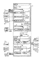
First, as shown in FIG. 1, the
[0034]
This
[0035]
As shown in FIG. 2, the device independent
[0036]
As described above, since the input profile can be applied by matrix calculation, the input image can be converted to a device-independent color image at high speed.
[0037]
Further, as shown in FIG. 3, the
[0038]
Since the input
[0039]
The image input device information shown in FIG. 2 is the characteristics of the image input device used for shooting, the setting state thereof (hereinafter referred to as shooting characteristics), and the environment information is the image of the object. Spectral data of illumination light (hereinafter referred to as “photographing illumination light data”) when photographing with the input device, and spectral data of illumination light (hereinafter, referred to as observation illumination light data) at a place where an image of the photographed object is desired to be observed. And information such as the statistical properties of the spectrum of the photographed object (hereinafter referred to as subject characteristics).
[0040]
By using this photographing characteristic, a color reproduction image can be accurately estimated for each image input device. Color reproduction is possible even when the image input device is a multispectral camera that captures a plurality of spectral images or when it is captured by a digital camera.
[0041]
By using the photographic illumination light data, the influence of the illumination light at the time of photographing can be canceled. In other words, the accurate spectral reflectance of the object itself can be calculated regardless of the illumination light (for example, fluorescent lamp, incandescent lamp, sun, etc.). Further, by using the observation illumination light data, it is possible to calculate the color under illumination at the place where the image is actually observed. By using subject characteristics, a color reproduction image can be accurately estimated even if the input image has only a small amount of spectral information.
[0042]
Next, environment information input to the
[0043]
This environment information is supplied from any of the
[0044]
When environmental information is obtained from the
[0045]
Further, when the environment information is obtained from the
[0046]
The
[0047]
The output
[0048]
For example, the
[0049]
The
[0050]
In such a configuration, as shown in FIG. 7, the
[0051]
The device independent color image sent to the output
[0052]
In this embodiment, the device-independent color image has a smaller data size than an image in a format that can be converted to illumination, and may be effective when storing or transmitting image data.
[0053]
In this configuration, parts that are the same as the parts shown in FIG. 6 are given the same reference numerals, and descriptions thereof are omitted.
[0054]
Next, a configuration for creating and using the input /
[0055]
The input / output
[0056]
With such a configuration, the input image needs to be converted only once, so that the processing speed is further increased compared to the configuration shown in FIG.
[0057]
FIG. 9 illustrates a specific configuration example when the color reproduction apparatus according to the first embodiment is actually constructed. The present embodiment is an example of a system that is constructed on computer software and creates a color reproduction image and displays it on a monitor.
[0058]
As shown in FIG. 9, a
[0059]
In each component part constructed on software by the
[0060]
The
[0061]
In such a configuration, it is necessary to create an input profile and an output profile before color reproduction image creation processing.
[0062]
For creating the input profile, the spectral data of the illumination light at the time of photographing or observation is measured using the
[0063]
The imaging characteristics of the
[0064]
The
[0065]
Based on the data measured by the
[0066]
In the present embodiment, a chromaticity meter is separately provided as monitor measurement, but a spectrometer used for illumination light data measurement can also be used.
[0067]
In order to create a color reproduction image of the measurement object, the
[0068]
If the
[0069]
In this embodiment, the color reproduction device is realized by a single personal computer, but a color reproduction device that accurately transmits colors between a plurality of personal computers connected to a network can also be realized.
[0070]
An example of a software processing algorithm will be described below. First, when the output signal of the multispectral camera is gi, gi is
[Equation 3]
It can be expressed. Actually, the stimulus value XYZ when a human observes the object is
[Expression 4]
So,
[Equation 5]
![]()
What is necessary is just to calculate the matrix M. t represents a transposed matrix. The evaluation function is
[Formula 6]
![]()
Design M to minimize. E [] represents an operator for obtaining an expected value.
[0075]
[Expression 7]
![]()
M obtained as is a least square filter,
[Equation 8]
Given in.
[0078]
E [f (λ) · f (λ ′)] in equation (6) represents the spectral correlation term of the measurement object. When the evaluation function is averagely reduced in all objects, it becomes a unit matrix, The filter M is as follows.
[0079]
[Equation 9]
If the object to be measured is limited to some extent and the spectral reflectance distribution can be expressed by a small number of bases, the color can be accurately estimated from a small number of spectral images. For example, in telemedicine, the skin color can be accurately reproduced from a small number of spectral images by measuring the spectral reflectance of the skin color and obtaining the correlation matrix in advance as a statistical property.
[0081]
That is, the input profile creation is to calculate Equation (6) when performing color reproduction processing using subject characteristics, and to calculate Equation (7) when subject properties are not used. The input profile operation unit is to apply the filter M to the signal obtained by the multispectral image capturing unit, that is, to calculate Equation (3).
[0082]
Next, a second embodiment of the color reproduction device according to the present invention will be described.
[0083]
As shown in FIG. 10, in the present embodiment, an
[0084]
In this information database, the aforementioned image input device information and environment information are stored in a database and can be referred to when creating an input profile. By making it possible to refer to these pieces of information freely when creating an input profile, the input image can be converted into a device-independent color image in an arbitrary environment. Of course, the information database may be saved in a network destination or a storage medium such as a CD-ROM, and called and referred to when it is created. It is also possible to provide an information database (not shown) having information relating to the same image output apparatus and to refer to it when creating an output profile. Therefore, a device independent color image can be converted into an output image in an arbitrary environment.
[0085]
Next, a third embodiment of the color reproduction device according to the present invention will be described with reference to FIGS. In this embodiment, the input image itself has a part of image input device information or environment information necessary for creating an input profile, and performs color correction of image data having a data structure capable of illumination conversion. is there.
[0086]
In the present embodiment, as shown in FIG. 11, an
[0087]
The
[0088]
Here, the device independent
[0089]
The illumination variable image data 55 includes, for example, a plurality of
[0090]
In this configuration, the image data itself input to the device independent
[0091]
Therefore, by making part of the image data, the image input device information, and the environment information into one data structure in the color
[0092]
Next, FIGS. 13 and 14 show and describe a modification of the above-described third embodiment.
[0093]
In this embodiment, the color correction unit as shown in FIG. 7 described above is divided into a pre-processing unit and a post-processing unit, and the image data format between them is approximated to the spectral reflectance data of the object (this) Is also a variable illumination image format) and is moved and transmitted.
[0094]
In this embodiment, the
[0095]
This color reproduction device is characterized in that an input image is pre-format-converted with photographing characteristics and photographing illumination light data to form an illumination-convertible data structure that approximates the spectral reflectance of an object.
[0096]
As an example of the illumination variable image data 58 represented by the illumination variable image format, FIG. 14 shows a format example of subject image data representing the spectral reflectance of the object.
[0097]
In the present modification, the captured input image is converted by the color
[0098]
Next, a specific configuration example of the above-described third embodiment will be described.
[0099]
FIG. 15 and FIG. 16 show and explain a first specific configuration example of the third embodiment.
[0100]
This embodiment uses a recording medium that records product image data and a database of various illumination light data in a data format that can be converted to illumination in order to confirm the color sample of the product using a personal computer. is there.
[0101]
First, for example, the CD-
[0102]
As this configuration, the product catalog viewer software and the illumination light database, a CD-
[0103]
This
[0104]
The input profile may be created by the
[0105]
According to this embodiment, the user inserts into the
[0106]
In this embodiment, image data is supplied using a storage medium, but data may be provided via the Internet or the like. In addition, the product is not limited to clothing such as clothes, but is effective for color confirmation of cosmetics, furniture, electrical appliances, paintings, and the like.
[0107]
Next, a second specific configuration example of the third embodiment will be described with reference to FIGS. 17 to 19.
[0108]
In this embodiment, as shown in FIG. 17, in addition to the first specific configuration example described above, an image captured by a digital camera is inserted into image data of a product read from a CD-ROM, Can freely convert lighting.
[0109]
As shown in FIG. 18, the
[0110]
Next, the color reproduction device includes a CD-
[0111]
In addition to the configuration of the first specific example, the
[0112]
In the color reproduction device configured as described above, when the product catalog viewer software is activated and the product catalog is displayed, the user's own face photograph (67a) taken with the
[0113]
In this embodiment, image data is supplied using a storage medium, but data may be provided via the Internet or the like. In addition, the product is not limited to clothing such as clothes, but is effective for color confirmation of cosmetics, furniture, electrical appliances, paintings, and the like.
[0114]
Next, a fourth embodiment of the color reproduction device according to the present invention will be described.
[0115]
The present embodiment includes an
[0116]
FIG. 20 shows a configuration of a multispectral camera that can simultaneously obtain a captured image of an object and a part of environment information that can be used in the present embodiment.
[0117]
In this configuration, the light beam collected by the photographing
[0118]
This frame-sequential multispectral camera captures a plurality of multispectral images while rotating a
[0119]
In the meantime, the
[0120]
The multispectral camera shown in FIG. 21 is an example in which the arrangement of spectrometers and the optical path in the camera shown in FIG. 20 are changed.
[0121]
This multispectral camera acquires spectral data of illumination light at the time of photographing directly from the outside by a
[0122]
Note that this embodiment can be applied to a multispectral camera using a plurality of bandpass filters, a multispectral camera using a wavelength tunable filter using liquid crystal, a multispectral camera in which an optical path is divided by a prism, or a digital camera. Of course it doesn't matter.
[0123]
Next, a fifth embodiment of the color reproduction device according to the present invention will be described.
[0124]
In this embodiment, an
[0125]
FIG. 22 shows a configuration of an example multispectral camera as the
[0126]
This multispectral camera is interposed between the taking
[0127]
This multispectral camera stores the filter characteristics of the filter attached to the
[0128]
Further, information on the taking
[0129]
Note that the present embodiment is not limited to a multispectral camera using a plurality of bandpass filters, a multispectral camera using a tunable filter using liquid crystal, a multispectral camera in which an optical path is divided by a prism or the like, a digital camera But of course it does n’t matter.
[0130]
Next, a sixth embodiment of the color reproduction device according to the present invention will be described.
[0131]
In the present embodiment, only the device
[0132]
As shown in FIG. 23, the
[0133]
Usually, offset light and external light are added to an image that is originally displayed.
[0134]
[Expression 10]
As shown in this equation (8), the obtained XYZ values are obtained by adding bias values (X0, Y0, Z0) to the RGB values to be output.
[0136]
Therefore, only the bias values of offset light and external light are measured, and the bias values are subtracted from the XYZ values input to the profile. By this processing, the output profile obtained in the dark room or the like can be used as it is, so that much labor for profile creation is not required. In particular,
## EQU11 ##
As shown in FIG. 8, the output profile may be applied after subtracting the bias values (X0, Y0, Z0) from the color to be displayed.
[0138]
Next, a seventh embodiment of the color reproduction device according to the present invention will be described.
[0139]
Usually, monitor offset light and external light are measured separately or simultaneously, and are subtracted from the XYZ values to be displayed. If the XYZ values due to monitor offset light are Ox, Oy, Oz and the XYZ values due to external light are Lx, Ly, Lz, the bias values X0 Y0, Z0 are
[Expression 12]
become. A conceptual diagram of the monitor tube surface is shown in FIG.
[0141]
FIG. 25 shows a configuration example in which a bias value is measured using a chromaticity meter.
[0142]
FIG. 25A shows a case where the XYZ values Ox, Oy, Oz are measured by the monitor offset light. The monitor and the chromaticity meter are installed in the dark room, and the monitor is turned on and R = G = B = 0 is output and the chromaticity value is detected. FIG. 25B shows a case where XYZ values Lx, Ly, Lz due to external light are measured, and FIG. 25C shows a case where bias values X0, Y0, Z0 are directly measured.
[0143]
FIG. 26 shows a configuration example of the device value conversion unit of FIG. 23 and its peripheral part.
[0144]
This device
With this configuration,
As shown in FIG. 25C, when the bias value is directly obtained, the
[0145]
In this embodiment, since it is not necessary to change the output profile at all, the output profile can be operated very simply and at high speed.
[0146]
Next, an eighth embodiment of the color reproduction device according to the present invention will be described.
[0147]
In the present embodiment, a bias detection sensor is provided and used for detection of monitor offset light and external light.
[0148]
As shown in FIG. 27A, the
[0149]
In this case, since the chromaticity value obtained from the sensor is not a value from reflection on the monitor tube surface, it is converted into XYZ values Lx, Ly, and Lz of external light by the external light calculation unit.
[0150]
The offset light of the monitor stabilizes after a while after the monitor is turned on, but the change in outside light is very large, particularly when outdoor light is incident, and changes rapidly with time.
[0151]
According to this configuration, it is possible to instantly capture a change in external light that changes rapidly, and it is possible to always realize stable color reproduction.
[0152]
FIGS. 28A and 28B show a configuration example of a chromaticity detection sensor that can detect both offset light and external light.
[0153]
FIG. 28C shows a modification. In this configuration, the
[0154]
Next, a ninth embodiment of the color reproduction device according to the present invention will be described.
[0155]
In the present embodiment shown in FIG. 29, a chromaticity meter is provided in a hood that blocks external light from the monitor in the configuration shown in FIG.
[0156]
When the influence of outside light is very large, accurate color reproduction is impossible even if the above-described outside light or offset processing is performed. In places where accurate color reproduction is required, such as recognizing an affected area at a medical site, a
[0157]
Therefore, the
[0158]
In this embodiment, when the
[0159]
In this embodiment, the bias value is detected when the
[0160]
Also, the bias value may be different depending on the area of the monitor screen. In such a case, a camera capable of measuring XYZ values is attached instead of the chromaticity meter, and the bias value is obtained for each pixel or each block of the image displayed on the
[0161]
Next, a description will be given of a tenth embodiment of the color reproduction device according to the present invention.
[0162]
In this embodiment, information necessary for profile creation is prepared in advance in the monitor, and a chromaticity meter is not required when creating a profile.
[0163]
As shown in FIG. 30, the
[0164]
The output
[0165]
In such an embodiment, the XYZ chromaticity values and tone curve data of the RGB phosphors according to various conditions are stored in each storage unit provided in the
[0166]
In the present embodiment, since the output profile is generated without using a chromaticity meter, the output profile can be operated very easily.
[0167]
In this embodiment, the XYZ chromaticity values and tone curve data of the RGB phosphors according to various conditions are stored inside the monitor. However, they are stored as file data in a personal computer or the like and read out as necessary. It may be used.
[0168]
Next, an eleventh embodiment of the color reproduction device according to the present invention will be described.
[0169]
In the present embodiment, a device value conversion unit that performs bias value correction using a table when referring to an output profile will be described.
[0170]
As shown in FIG. 31, the device value conversion unit subtracts bias values X0, Y0, and Z0 from an input XYZ value and an R table 123, a G table 124, and a B table 125 that are output profiles.
[0171]
Therefore, RGB values corresponding to the input XYZ values can be output according to the output profile of each table.
[0172]
In the present embodiment, the method described in the seventh embodiment is effective for a monitor that satisfies the expression (11), but there is a monitor that does not satisfy the expression (11) in other monitors.
[0173]
In that case, a method is known in which RGB values corresponding to XYZ values are tabulated. In this case, the bias value is corrected by subtracting the bias values X0, Y0 and Z0 from the XYZ values to be output, as in the seventh embodiment, and referring to the table.
In this embodiment, even when a table is used to refer to the output profile, the bias value of offset light or external light can be corrected well.
[0174]
As mentioned above, although demonstrated based on embodiment, this invention includes the following inventions.
[0175]
(1). In a color reproduction device that performs color conversion on an image photographed by an image input device, color conversion by color correction means, and display or print output on the image output device
The color correction means is
A color reproduction device that performs color conversion from an input image to an output image using information relating to a color reproduction environment comprising information at the time of photographing and observation, information relating to the image input device, and information relating to the image output device .
[0176]
(Corresponding Embodiment) The first embodiment corresponds.
[0177]
(Effect) When performing color reproduction, color correction is performed based on information on a color reproduction environment including information at the time of photographing and observation, information on an image input device, and information on an image output device. As described above, it is possible to convert an input image into an output image with high accuracy by considering various information.
[0178]
(2). The color reproduction device according to item (1), wherein information on an object to be photographed is further used as information on the color reproduction environment.
[0179]
(Corresponding Embodiment) All the embodiments correspond. See especially the first embodiment.
[0180]
(Function and effect) By using the information of the object to be photographed as the color reproduction environment information, the input image can be accurately converted into an output image even if the input image has only a small amount of spectral information.
[0181]
(3). In a color reproduction device that performs color conversion on an image photographed by an image input device, color conversion by color correction means, and display or print output on the image output device
The color correction means is
An input profile creation unit that creates an input profile according to information about the image input device and information about the color reproduction environment;
A device-independent color image conversion unit having an input profile operation unit that converts an input image into a device-independent color image with reference to the input profile;
An output profile creation unit that creates an output profile according to information on the image output device;
Device value conversion means having an output profile operation unit that converts a device-independent color image into an output image with reference to the output profile;
The color reproduction device according to the above items (1) and (2), characterized by comprising:
[0182]
(Corresponding Embodiment) The first embodiment corresponds.
[0183]
(Effect) When performing color reproduction, color correction is performed based on an input profile based on information on the color reproduction environment and information on the image input device and an output profile based on information on the image output device, As described above, an input image can be converted into an output image with high accuracy by using an input profile and an output profile in consideration of various information.
[0184]
(4). In a color reproduction device that performs color conversion on an image photographed by an image input device, color conversion by color correction means, and display or print output on the image output device
The color correction means is
An input / output profile creation unit that creates an input / output profile based on information on the image input device, information on the color reproduction environment, and information on the image output device;
With reference to the input / output profile, an input / output profile operation unit that converts a captured image into an output image;
The color reproduction device according to the above items (1) and (2), characterized by comprising:
[0185]
(Corresponding Embodiment) The first embodiment corresponds.
[0186]
(Operational effect) Since the image captured by the input / output profile operation unit is converted into an output image, the image conversion is performed only once, so that the color correction process is further accelerated.
[0187]
(5). The information about the image input device is information obtained from the characteristics of the image input device used for shooting and the setting state thereof, and the information about the color reproduction environment is an image input of an object to be a subject. The color reproduction device according to (1) above, which is spectral data of illumination light at the time of photographing with the device and spectral data of illumination light at a place where the photographed object image is desired to be observed.
[0188]
(Corresponding Embodiment) All the embodiments correspond.
[0189]
(Function / Effect) When performing color reproduction, information on the color reproduction environment consisting of information at the time of photographing and observation, that is, spectral data of illumination light when photographing an image of an object to be a subject with an image input device and photographing Color correction is performed based on an input profile based on spectral data of illumination light at a location where an image of an object is desired to be observed and information on the image input device, and an output profile based on information on the image output device. As described above, by using an input profile and an output profile in consideration of various information, an input image can be converted into an output image with high accuracy.
[0190]
(6). The information on the object to be photographed added to the color reproduction environment is spectrum statistical data of the object to be photographed.
[0191]
(Corresponding Embodiment) All the embodiments correspond.
[0192]
(Effect) By using the information of the object to be photographed as the information of the color reproduction environment regarding the input profile, that is, the spectrum statistics data of the object, the input image can be accurately converted into the output image even if the input image has little spectrum information. Can be converted.
(7). The device independent color image converting means is
A selection unit that selects appropriate information for the information about the image input device and the information about the color reproduction environment, an input profile creation unit that creates an input profile in a matrix format based on the selected information,
The color reproduction apparatus according to (3), further comprising: an input profile operation unit that converts an input image into a device-independent color image by matrix calculation using the matrix-type input profile.
[0193]
(Corresponding Embodiment) The first embodiment corresponds.
[0194]
(Operational Effect) Since the input profile can be operated by matrix calculation, the input image can be converted into a device-independent color image at high speed.
[0195]
(8). The input profile creation unit, the input profile operation unit, the output profile creation unit, and the output profileAction partHas a selection part of various information input to each,
The input image, the information about the image input device, the information about the color reproduction environment, and the information about the image output device can be obtained from any of the image input device, a dedicated input device, a network connected to an external device, and a storage medium. The color reproduction device according to item (3), wherein the color reproduction device is supplied.
[0196]
(Corresponding Embodiment) The first embodiment corresponds.
[0197]
(Operation and effect) Various information can be selectively obtained from an image input device, a dedicated input device, a network connected to an external device, or a storage medium by a selection unit of various information. Therefore, color correction can be performed using arbitrary information (real-time information, past information, etc.) when creating an input or output profile or when a profile is applied.
[0198]
(9). The input profile creation unit, the output profile operation unit, and the input / output profile operation unit each have a selection unit for various information to be input to each,
The input image, the information about the image input device, the information about the color reproduction environment, and the information about the image output device can be obtained from any of the image input device, a dedicated input device, a network connected to an external device, and a storage medium. The color reproduction device according to item (4), wherein the color reproduction device is supplied.
[0199]
(Corresponding Embodiment) The first embodiment corresponds.
[0200]
(Operation and effect) Various information can be selectively obtained from an image input device, a dedicated input device, a network connected to an external device, or a storage medium by a selection unit of various information. Therefore, it is possible to perform color correction using arbitrary information (real-time information, past information, etc.) when creating an input / output profile or when an input / output profile is applied.
[0201]
(10). The color correction means is
An information database in which at least one of the information on the image input device, the information on the color reproduction environment, and the information on the image output device is databased,
The color reproduction device according to (3) and (4) above, wherein desired data is selectively obtained when an input profile is created or when an output profile is created.
[0202]
(Corresponding Embodiment) The second embodiment corresponds.
[0203]
(Operation and Effect) When an input profile is created or an output profile is created, desired data can be selectively obtained by this information database, so that an input image can be converted into an output image in an arbitrary environment.
[0204]
(11). The color reproduction device further includes a color correction preprocessing unit,
The color correction pre-processing unit includes image data captured by the image input device, information on the image input device, spectral data of illumination light when an image of an object to be a subject is captured by the image input device, Using at least one of the spectrum statistics data of the object to be photographed, the format is converted into a data structure that can be converted to illumination, and the color correction means processes the image data that can be converted to illumination, under a desired observation illumination light. The color reproduction apparatus according to the above items (3) and (4), wherein the color reproduction device outputs the corrected color.
[0205]
(Corresponding Embodiment) The third embodiment and its modification correspond.
[0206]
(Effect) The color correction pre-processing unit uses the image data of the input image as at least one of the information related to the image input device, the spectrum data of the illumination light when photographing the subject, and the spectrum statistical data of the photographing object. Since the format is converted to a data structure that can be converted to illumination, it is possible to obtain easy-to-use data for data processing in the color correction means.
[0207]
(12). The image input device includes image data detection means for detecting image data from a light image by photoelectric conversion, and a spectroscope for detecting spectrum data.
The above image data;
Among the information on the color reproduction environment, it is possible to simultaneously measure spectral data of illumination light when photographing an image of an object to be a subject with the image input device or spectrum statistical data of the object to be photographed. The color reproduction device according to any one of (3) and (4) above, which is characterized.
[0208]
(Corresponding Embodiment) The fourth embodiment corresponds.
[0209]
(Function and effect) Since the image input device includes the image data detecting means and the spectroscope, the spectrum data of the subject illumination light at the time of shooting (image input) or the shooting of the image data and information on the color reproduction environment The spectrum statistical data of the object can be acquired simultaneously.
[0210]
(13). The image input device includes a storage unit that stores information related to the image input device,
The color reproduction device described in the above items (3) and (4), wherein desired information relating to the image input device can be freely read out by the color correction means.
[0211]
(Corresponding Embodiment) The fifth embodiment corresponds.
[0212]
(Effect) Since the image input apparatus itself includes a storage unit for storing information related to the image input apparatus, desired information related to the image input apparatus can be freely read out to the color correction means during color correction.
[0213]
(14). A bias in which the device value converting means subtracts a bias value of a color signal due to ambient external light irradiated on an output surface of the image output device and an offset of the image output device from the device independent color image; The color reproduction device according to item (3), further comprising a subtracting unit, wherein after the bias value is subtracted, the output profile application unit converts the output value into an output image with reference to the output profile.
[0214]
(Corresponding Embodiment) The sixth to ninth embodiments correspond.
[0215]
(Function and effect) The bias value of the color signal due to the ambient light irradiated on the output surface of the image output device by the bias subtracting unit and the offset of the image output device is subtracted from the device independent color image, and then In addition, since the output profile is converted into the output image while referring to the output profile, the output profile obtained in advance in the dark room can be used as it is, and the output profile creation does not require much effort. .
[0216]
【The invention's effect】
As described above in detail, according to the present invention, color reproduction comprising information on an image input device, information on spectral data of illumination light at the time of photographing and observation, and information on statistical properties of the spectrum of the photographed object, etc. Image conversion with reference to environmental information is possible, and the shooting location and reproduction location of the image can be remoted.Of the shooting locationA color reproduction device that enables accurate color reproduction with the output profile applied easily and at high speed even when the ambient light fluctuates., Color correction apparatus, color reproduction method, and color reproduction programCan be provided.
[Brief description of the drawings]
FIG. 1 is a diagram showing a schematic configuration of a first embodiment as a color reproduction device according to the present invention.
2 is a diagram illustrating a configuration example of a device independent color conversion unit and a device value conversion unit illustrated in FIG. 1. FIG.
FIG. 3 is a diagram illustrating another configuration example of the color correction unit illustrated in FIG. 1;
FIG. 4 is a diagram for describing a configuration example of a device independent color conversion unit.
FIG. 5 is a diagram for describing an example of an input method of environment information input to a correction unit.
FIG. 6 is a diagram for describing an example of an input method of environment information input to a correction unit.
FIG. 7 is a diagram illustrating a configuration example of a color correction unit divided into a pre-processing color correction unit and a post-processing color correction unit.
FIG. 8 is a diagram illustrating a configuration example in which an input / output profile in which an input profile and an output profile are linked is created and used.
FIG. 9 is a diagram illustrating a specific configuration example of a color reproduction device according to the first embodiment.
FIG. 10 is a diagram showing a schematic configuration example of a second embodiment of a color reproduction device according to the present invention.
FIG. 11 is a diagram for explaining illumination variable image data input to a color correction unit according to a third embodiment.
FIG. 12 is a diagram illustrating a format example of illumination variable image data used in the third embodiment.
FIG. 13 is a diagram showing a modification of the third embodiment.
FIG. 14 is a diagram illustrating a format example of illumination variable image data in a modification of the third embodiment.
FIG. 15 is a diagram illustrating an appearance of a first specific configuration example according to a third embodiment.
FIG. 16 is a diagram illustrating a first specific configuration example of the third embodiment.
FIG. 17 is a diagram illustrating an appearance of a second specific configuration example according to the third embodiment.
FIG. 18 is a diagram illustrating a configuration example of a digital camera used in a second specific configuration example of the third embodiment.
FIG. 19 is a diagram illustrating a second specific configuration example of the third embodiment.
FIG. 20 is a diagram showing a configuration example of a multispectral camera used in the fourth embodiment of the color reproduction device according to the present invention.
FIG. 21 is a diagram illustrating a second configuration example of the multispectral camera used in the fourth embodiment of the color reproduction device according to the present invention;
FIG. 22 is a diagram showing a configuration example of a multispectral camera used in the fifth embodiment of the color reproduction device according to the present invention.
FIG. 23 is a diagram illustrating a configuration example of a device value conversion unit in a sixth embodiment of the color reproduction device according to the present invention.
FIG. 24 is a conceptual diagram of a monitor tube surface in a seventh embodiment of the color reproduction device according to the present invention.
FIG. 25 is a diagram illustrating a configuration example in which a bias value is measured using a chromaticity meter according to a seventh embodiment.
FIG. 26 is a diagram illustrating a configuration example of a device value conversion unit in the seventh embodiment.
FIG. 27 is a diagram for explaining a chromaticity detection sensor in an eighth embodiment of the color reproduction device according to the present invention;
FIG. 28 is a diagram for explaining a modification of the chromaticity detection sensor according to the eighth embodiment.
FIG. 29 is a diagram showing a configuration of a ninth embodiment of a color reproduction device according to the present invention.
FIG. 30 is a diagram showing a configuration of a tenth embodiment of a color reproduction device according to the present invention.
FIG. 31 is a diagram showing a configuration of a device value conversion unit in an eleventh embodiment of a color reproduction device according to the present invention.
FIG. 32 is a diagram illustrating a schematic configuration example of a conventional color reproduction device.
FIG. 33 is a diagram illustrating a schematic configuration example of a color correction unit of a conventional color reproduction device.
FIG. 34 is a diagram illustrating a configuration example in which a conventional color reproduction device can reproduce an image at a location away from a shooting location.
FIG. 35 is a diagram illustrating a configuration example of an output profile creation unit in a color correction unit of a conventional color reproduction device.
FIG. 36 is a diagram illustrating a configuration example for performing a series of processing for matrix conversion and γ correction in a color correction unit of a conventional color reproduction device.
[Explanation of symbols]
1 ... Image input device
2. Image output device
3. Color correction unit
4 ... Device independent color converter
4a ... Input profile
5 ... Device value converter
5a ... Output profile
6 ... Input profile creation section
7 ... Input profile action part
Claims (60)
上記色補正手段は、
上記入力画像を撮影した画像入力装置の撮影特性と、上記入力画像を撮影する時の照明光のスペクトルデータである撮影照明光データと、を用いて入力プロファイルを算出する入力プロファイル作成部と、
上記入力プロファイルを参照して、上記入力画像をデバイスインデペンデントカラー画像に変換する入力プロファイル作用部と、
を具備することを特徴とする色再現装置。In a color reproduction device including color correction means for performing color conversion of an input image, which is an image of an object to be photographed,
The color correction means is
An input profile creating unit that calculates an input profile using photographing characteristics of an image input device that has photographed the input image and photographing illumination light data that is spectral data of illumination light when photographing the input image;
With reference to the input profile, an input profile operation unit that converts the input image into a device-independent color image;
A color reproduction device comprising:
上記色補正前処理部は、上記入力画像のデータを、上記画像入力装置の撮影特性及び上記撮影照明光データを用いて色変換可能なデータ構造を有する照明可変画像データにフォーマット変換し、 The color correction preprocessing unit converts the format of the input image data into illumination variable image data having a data structure capable of color conversion using the imaging characteristics of the image input device and the imaging illumination light data.
上記入力プロファイル作成部は、上記照明可変画像データから分割された上記撮影特性と上記撮影照明光データとを用いて上記入力プロファイルを算出し、The input profile creation unit calculates the input profile using the shooting characteristics and the shooting illumination light data divided from the illumination variable image data,
上記入力プロファイル作用部は、上記入力プロファイルを参照して、上記照明可変画像データから分割された上記入力画像のデータを上記デバイスインデペンデントカラー画像に変換することを特徴とする請求項1に記載の色再現装置。The input profile operation unit refers to the input profile and converts the input image data divided from the illumination variable image data into the device independent color image. Color reproduction device.
上記入力プロファイル作成部は、The input profile creation unit
上記色補正前処理部に設けられ、上記画像入力装置の撮影特性と、上記撮影照明光データと、を用いて第1の入力プロファイルを算出する第1の入力プロファイル作成部と、A first input profile creation unit that is provided in the color correction pre-processing unit and calculates a first input profile using the photographing characteristics of the image input device and the photographing illumination light data;
上記色補正後処理部に設けられ、上記対象物の画像を観察したい場所の照明光のスペクトルデータである観察照明光データおよび上記対象物のスペクトル統計データの少なくとも1つを用いて第2の入力プロファイルを算出する第2の入力プロファイル作成部と、A second input using at least one of observation illumination light data, which is provided in the color correction post-processing unit, and is spectral data of illumination light at a location where an image of the object is desired to be observed, and spectrum statistical data of the object. A second input profile creation unit for calculating a profile;
を備え、With
上記入力プロファイル作用部は、The input profile action unit is
上記色補正前処理部に設けられ、上記第1の入力プロファイルを参照して、上記入力画像のデータを、上記対象物の分光反射率を近似する色変換可能なデータ構造を有する照明可変画像データにフォーマット変換する第1の入力プロファイル作用部と、Illumination variable image data provided in the color correction pre-processing unit and having a data structure capable of color conversion that approximates the spectral reflectance of the object with respect to the input image data with reference to the first input profile A first input profile action unit for format conversion to
上記色補正後処理部に設けられ、上記第2の入力プロファイルを参照して、上記色補正前処理部から伝送された上記照明可変画像データを上記デバイスインデペンデントカラー画像に変換する第2の入力プロファイル作用部と、A second color correction unit that is provided in the color correction post-processing unit and converts the illumination variable image data transmitted from the color correction pre-processing unit into the device-independent color image with reference to the second input profile; An input profile action unit;
を備えることを特徴とする請求項1に記載の色再現装置。The color reproduction device according to claim 1, further comprising:
上記入力プロファイル作用部は、上記マトリックス形式の入力プロファイルを用いてマトリックス演算により上記デバイスインデペンデントカラー画像に変換することを特徴とする請求項1乃至請求項7のうちのいずれか1つに記載の色再現装置。The said input profile action part converts into the said device independent color image by matrix calculation using the said input profile of a matrix format, The said any one of Claim 1 thru | or 7 characterized by the above-mentioned. Color reproduction device.
上記入力画像、上記画像入力装置の撮影特性、及び上記撮影照明光データが、上記画像入力装置、専用に設けた入力装置、外部の装置と接続するネットワーク、記憶媒体のいずれかから供給されることを特徴とする請求項1乃至請求項8のうちのいずれか1つに記載の色再現装置。The input image, the photographing characteristics of the image input device, and the photographing illumination light data are supplied from any of the image input device, a dedicated input device, a network connected to an external device, or a storage medium. The color reproduction device according to claim 1, wherein the color reproduction device is a color reproduction device.
画像出力装置に関する情報を用いて出力プロファイルを算出する出力プロファイル作成部と、An output profile creation unit that calculates an output profile using information about the image output device;
上記出力プロファイルを参照して、上記デバイスインデペンデントカラー画像を上記画像出力装置で出力する出力画像に変換する出力プロファイル作用部と、With reference to the output profile, an output profile action unit that converts the device-independent color image into an output image output by the image output device;
をさらに備えることを特徴とする請求項1乃至請求項10のうちのいずれか1つに記載の色再現装置。The color reproduction device according to claim 1, further comprising:
上記色補正前処理部は、The color correction pre-processing unit
上記入力プロファイル作成部と、The input profile creation unit;
上記入力プロファイル作用部と、The input profile action unit;
を備え、上記入力プロファイル作用部で変換された上記デバイスインデペンデントカラー画像を上記色補正後処理部に伝送し、The device independent color image converted by the input profile action unit is transmitted to the color correction post-processing unit,
上記色補正後処理部は、The color correction post-processing unit
画像出力装置に関する情報を用いて出力プロファイルを算出する出力プロファイル作成部と、An output profile creation unit that calculates an output profile using information about the image output device;
上記出力プロファイルを参照して、上記デバイスインデペンデントカラー画像を上記画像出力装置で出力する出力画像に変換する出力プロファイル作用部と、With reference to the output profile, an output profile action unit that converts the device-independent color image into an output image output by the image output device;
を備えることを特徴とする請求項1、請求項6、請求項7、請求項8、請求項9及び請求項10のうちのいずれか1つに記載の色再現装置。The color reproduction device according to any one of claims 1, 6, 7, 8, 9, and 10.
上記デバイスインデペンデントカラー画像から上記画像出力装置の出力面に照射される周囲の外光と、上記画像出力装置のオフセットとによる色信号のバイアス値を減算するバA bar for subtracting a bias value of a color signal due to ambient ambient light irradiating the output surface of the image output device and an offset of the image output device from the device independent color image. イアス減算部をさらに備え、It further includes an ias subtraction unit,
上記出力プロファイル作用部は、上記バイアス減算部によりバイアス値を減算した後に、上記出力プロファイルを参照しながら上記出力画像に変換することを特徴とする請求項11又は請求項12に記載の色再現装置。The color reproduction device according to claim 11 or 12, wherein the output profile operation unit converts the output image while referring to the output profile after the bias value is subtracted by the bias subtraction unit. .
上記色補正手段は、The color correction means is
上記入力画像を撮影した画像入力装置の撮影特性と、上記入力画像を撮影する時の照明光のスペクトルデータである撮影照明光データと、画像出力装置に関する情報と、を用いて入出力プロファイルを算出する入出力プロファイル作成部と、The input / output profile is calculated using the imaging characteristics of the image input device that captured the input image, the captured illumination light data that is the spectral data of the illumination light when capturing the input image, and the information related to the image output device. An input / output profile creation unit
上記入出力プロファイルを参照して、上記入力画像を上記画像出力装置で出力する出力画像に変換する入出力プロファイル作用部と、 With reference to the input / output profile, an input / output profile operation unit that converts the input image into an output image output by the image output device;
を具備することを特徴とする色再現装置。A color reproduction device comprising:
上記色補正前処理部は、上記入力画像のデータを、上記画像入力装置の撮影特性及び上記撮影照明光データを用いて色変換可能なデータ構造を有する照明可変画像データにフォーマット変換し、The color correction preprocessing unit converts the format of the input image data into illumination variable image data having a data structure capable of color conversion using the imaging characteristics of the image input device and the imaging illumination light data.
上記入出力プロファイル作成部は、上記照明可変画像データから分割された上記撮影特性及び上記撮影照明光データを用いるとともに、上記画像出力装置に関する情報を用いて上記入出力プロファイルを算出し、The input / output profile creating unit uses the photographing characteristics and the photographing illumination light data divided from the illumination variable image data, calculates the input / output profile using information on the image output device,
上記入出力プロファイル作用部は、上記入出力プロファイルを参照して、上記照明可変画像データから分割された上記入力画像のデータを上記デバイスインデペンデントカラー画像に変換することを特徴とする請求項14に記載の色再現装置。15. The input / output profile operation unit refers to the input / output profile and converts the input image data divided from the illumination variable image data into the device independent color image. The color reproduction device described in 1.
上記画像入力装置で撮影する時の照明光を検出する照明検出センサと、An illumination detection sensor for detecting illumination light when photographing with the image input device;
上記照明検出センサで検出された上記照明光の信号を処理する撮影照明データ検出部と、A photographing illumination data detector for processing the illumination light signal detected by the illumination detection sensor;
を備えることを特徴とする請求項17又は請求項18に記載の色再現装置。The color reproduction device according to claim 17, further comprising:
上記色補正手段は、上記入力プロファイルを作成するための上記撮影照明光データを得るために上記分光計を制御する照明光データ測定部を備えることを特徴とする請求項17又は請求項18に記載の色再現装置。The said color correction means is provided with the illumination light data measurement part which controls the said spectrometer in order to obtain the said imaging | photography illumination light data for creating the said input profile, The Claim 17 or Claim 18 characterized by the above-mentioned. Color reproduction device.
上記色度検出センサからの色度値をXYZ値に変換する外光演算部と、An external light calculation unit that converts chromaticity values from the chromaticity detection sensor into XYZ values;
をさらに備え、Further comprising
上記色度検出センサが上記画像出力装置に取り付け可能に構成されていることを特徴とする請求項21に記載の色再現装置。The color reproduction device according to claim 21, wherein the chromaticity detection sensor is configured to be attachable to the image output device.
上記スペクトル検出センサが上記画像出力装置に取り付け可能に構成されていることを特徴とする請求項21又は請求項22に記載の色再現装置。23. The color reproduction device according to claim 21, wherein the spectrum detection sensor is configured to be attachable to the image output device.
上記画像入力装置で撮影する時の照明光を検出する照明検出センサと、An illumination detection sensor for detecting illumination light when photographing with the image input device;
上記照明検出センサで検出された上記照明光の信号を処理する撮影照明データ検出部と、A photographing illumination data detector for processing the illumination light signal detected by the illumination detection sensor;
を備えることを特徴とする請求項25又は請求項26に記載の色再現装置。27. The color reproduction device according to claim 25 or claim 26, comprising:
上記色補正手段は、上記入力プロファイルを作成するための上記撮影照明光データを得るために上記分光計を制御する照明光データ測定部を備えることを特徴とする請求項25又は請求項26に記載の色再現装置。The said color correction means is provided with the illumination light data measurement part which controls the said spectrometer in order to obtain the said imaging | photography illumination light data for creating the said input profile, The Claim 25 or Claim 26 characterized by the above-mentioned. Color reproduction device.
上記色度検出センサからの色度値をXYZ値に変換する外光演算部と、An external light calculation unit that converts chromaticity values from the chromaticity detection sensor into XYZ values;
をさらに備え、Further comprising
上記色度検出センサが上記画像出力装置に取り付け可能に構成されていることを特徴とする請求項25乃至請求項28のうちのいずれか1つに記載の色再現装置。The color reproduction device according to any one of claims 25 to 28, wherein the chromaticity detection sensor is configured to be attachable to the image output device.
上記スペクトル検出センサが上記画像出力装置に取り付け可能に構成されていることを特徴とする請求項25乃至請求項29のうちのいずれか1つに記載の色再現装置。30. The color reproduction device according to claim 25, wherein the spectrum detection sensor is configured to be attachable to the image output device.
上記色補正部は、The color correction unit
上記画像入力部の撮影特性と、上記入力画像を撮影する時の照明光のスペクトルデータである撮影照明光データと、を用いて入力プロファイルを算出する入力プロファイル作成Creating an input profile that calculates an input profile using the imaging characteristics of the image input unit and imaging illumination light data that is spectral data of illumination light when the input image is captured 部と、And
上記入力プロファイルを参照して、上記入力画像をデバイスインデペンデントカラー画像に変換する入力プロファイル作用部と、With reference to the input profile, an input profile operation unit that converts the input image into a device-independent color image;
を具備し、上記デバイスインデペンデントカラー画像を出力することを特徴とする色再現装置。And a device for reproducing the device-independent color image.
上記色補正部は、The color correction unit
上記画像入力部の撮影特性と、上記入力画像を撮影する時の照明光のスペクトルデータである撮影照明光データと、を用いて入力プロファイルを算出する入力プロファイル作成部と、An input profile creation unit that calculates an input profile using the imaging characteristics of the image input unit and imaging illumination light data that is spectral data of illumination light when the input image is captured;
上記入力プロファイルを参照して、上記入力画像をデバイスインデペンデントカラー画像に変換する入力プロファイル作用部と、With reference to the input profile, an input profile operation unit that converts the input image into a device-independent color image;
画像出力装置に関する情報を用いて出力プロファイルを算出する出力プロファイル作成部と、An output profile creation unit that calculates an output profile using information about the image output device;
上記出力プロファイルを参照して、上記デバイスインデペンデントカラー画像を上記画像出力装置で出力する出力画像に変換する出力プロファイル作用部と、With reference to the output profile, an output profile action unit that converts the device-independent color image into an output image output by the image output device;
を具備し、上記出力画像を出力することを特徴とする色再現装置。And a color reproduction device for outputting the output image.
上記入力画像、上記画像入力装置の撮影特性、及び上記撮影照明光データが、上記画像入力装置、専用に設けた入力装置、外部の装置と接続するネットワーク、記憶媒体のいずれかから供給されることを特徴とする請求項32乃至請求項35のうちのいずれか1つに記載の色再現装置。The input image, the photographing characteristics of the image input device, and the photographing illumination light data are supplied from any of the image input device, a dedicated input device, a network connected to an external device, or a storage medium. 36. The color reproduction device according to any one of claims 32 to 35, wherein:
上記画像入力部で撮影する時の照明光を検出する照明検出センサと、An illumination detection sensor for detecting illumination light when photographing with the image input unit;
上記照明検出センサで検出された上記照明光の信号を処理する撮影照明データ検出部と、A photographing illumination data detector for processing the illumination light signal detected by the illumination detection sensor;
を備えることを特徴とする請求項32乃至請求項38のうちのいずれか1つに記載の色再現装置。The color reproduction device according to any one of claims 32 to 38, further comprising:
上記色補正部は、上記入力プロファイルを作成するための照明光データを得るために上記分光計を制御する照明光データ測定部を備えることを特徴とする請求項32乃至請求項38のうちのいずれか1つに記載の色再現装置。The said color correction | amendment part is provided with the illumination light data measurement part which controls the said spectrometer in order to obtain the illumination light data for creating the said input profile, Any of Claim 32 thru | or 38 characterized by the above-mentioned. The color reproduction apparatus as described in any one.
上記色補正部は、The color correction unit
上記画像入力部の撮影特性と、上記入力画像を撮影する時の照明光のスペクトルデータである撮影照明光データと、画像出力装置に関する情報と、を用いて入出力プロファイルを算出する入出力プロファイル作成部と、Input / output profile creation that calculates an input / output profile using imaging characteristics of the image input unit, imaging illumination light data that is spectral data of illumination light when the input image is captured, and information about the image output device And
上記入出力プロファイルを参照して、上記入力画像を上記画像出力装置で出力する出力画像に変換する入出力プロファイル作用部と、With reference to the input / output profile, an input / output profile operation unit that converts the input image into an output image output by the image output device;
を具備し、上記出力画像を出力することを特徴とする色再現装置。And a color reproduction device for outputting the output image.
上記入力画像を撮影した画像入力装置の撮影特性と、上記入力画像を撮影する時の照明光のスペクトルデータである撮影照明光データと、を用いて入力プロファイルを算出する入力プロファイル作成部と、An input profile creating unit that calculates an input profile using photographing characteristics of an image input device that has photographed the input image and photographing illumination light data that is spectral data of illumination light when photographing the input image;
上記入力プロファイルを参照して、上記入力画像をデバイスインデペンデントカラー画像に変換する入力プロファイル作用部と、With reference to the input profile, an input profile operation unit that converts the input image into a device-independent color image;
を具備することを特徴とする色補正装置。A color correction apparatus comprising:
上記色補正過程は、The color correction process is
上記入力画像を撮影した画像入力手段の撮影特性と、上記入力画像を撮影する時の照明光のスペクトルデータである撮影照明光データと、を用いて入力プロファイルを算出する入力プロファイル作成過程と、An input profile creation process for calculating an input profile using imaging characteristics of image input means that captured the input image and imaging illumination light data that is spectral data of illumination light when the input image is captured,
上記入力プロファイルを参照して、上記入力画像をデバイスインデペンデントカラー画像に変換する入力プロファイル作用過程と、With reference to the input profile, an input profile operation process for converting the input image into a device-independent color image;
を備えることを特徴とする色再現方法。A color reproduction method characterized by comprising:
上記入力プロファイル作成過程において、上記照明可変画像データから分割された上記撮影特性と上記撮影照明光データとを用いて上記入力プロファイルを算出し、In the input profile creation process, the input profile is calculated using the shooting characteristics and the shooting illumination light data divided from the illumination variable image data,
上記入力プロファイル作用過程において、上記入力プロファイルを参照して、上記照明可変画像データから分割された上記入力画像のデータを上記デバイスインデペンデントカラー画像に変換することを特徴とする請求項43に記載の色再現方法。44. The process according to claim 43, wherein, in the process of operating the input profile, the input image data divided from the illumination variable image data is converted into the device-independent color image with reference to the input profile. Color reproduction method.
上記入力プロファイル作成過程は、The above input profile creation process
上記色補正前処理過程において、上記画像入力手段の撮影特性と、上記撮影照明光データと、を用いて第1の入力プロファイルを算出する第1の入力プロファイル作成過程と、A first input profile creation step of calculating a first input profile using the photographing characteristics of the image input means and the photographing illumination light data in the color correction pre-processing step;
上記色補正後処理過程において、上記対象物の画像を観察したい場所の照明光のスペクトルデータである観察照明光データおよび上記対象物のスペクトル統計データの少なくとも1つを用いて第2の入力プロファイルを算出する第2の入力プロファイル作成過程と、In the post-color correction post-process, a second input profile is obtained using at least one of observation illumination light data that is spectrum data of illumination light at a place where an image of the object is to be observed and spectrum statistical data of the object. A second input profile creation process to calculate;
を備え、With
上記入力プロファイル作用過程は、The input profile action process is
上記色補正前処理過程において、上記第1の入力プロファイルを参照して、上記入力画像のデータを、上記対象物の分光反射率を近似する色変換可能なデータ構造を有する照明可変画像データにフォーマット変換する第1の入力プロファイル作用過程と、In the pre-color correction process, the input image data is formatted into illumination variable image data having a data structure capable of color conversion that approximates the spectral reflectance of the object with reference to the first input profile. A first input profile action process to convert;
上記色補正後処理過程において、上記第2の入力プロファイルを参照して、上記照明可変画像データを上記デバイスインデペンデントカラー画像に変換する第2の入力プロファイル作用過程と、In the post-color correction process, a second input profile operation process for converting the illumination variable image data into the device independent color image with reference to the second input profile;
を備えることを特徴とする請求項43に記載の色再現方法。The color reproduction method according to claim 43, further comprising:
画像出力手段に関する情報を用いて出力プロファイルを算出する出力プロファイル作成過程と、An output profile creation process for calculating an output profile using information about the image output means;
上記出力プロファイルを参照して、上記デバイスインデペンデントカラー画像を上記画像出力手段で出力する出力画像に変換する出力プロファイル作用過程と、With reference to the output profile, an output profile operation process for converting the device independent color image into an output image output by the image output means;
をさらに備えることを特徴とする請求項43乃至請求項45のうちのいずれか1つに記載の色再現方法。46. The color reproduction method according to any one of claims 43 to 45, further comprising:
上記色補正過程は、The color correction process is
上記入力画像を撮影した画像入力手段の撮影特性と、上記入力画像を撮影する時の照明光のスペクトルデータである撮影照明光データと、画像出力手段に関する情報と、を用いて入出力プロファイルを算出する入出力プロファイル作成過程と、The input / output profile is calculated using the imaging characteristics of the image input unit that captured the input image, the imaging illumination light data that is the spectral data of the illumination light when capturing the input image, and the information about the image output unit. I / O profile creation process to
上記入出力プロファイルを参照して、上記入力画像を上記画像出力手段で出力する出力画像に変換する入出力プロファイル作用過程と、With reference to the input / output profile, an input / output profile operation process for converting the input image into an output image output by the image output means;
を備えることを特徴とする色再現方法。A color reproduction method characterized by comprising:
上記入出力プロファイル作成過程において、上記照明可変画像データから分割された上記撮影特性及び上記撮影照明光データを用いるとともに、上記画像出力手段に関する情報を用いて上記入出力プロファイルを算出し、In the input / output profile creation process, using the shooting characteristics and the shooting illumination light data divided from the illumination variable image data, calculating the input / output profile using information on the image output means,
上記入出力プロファイル作用過程において、上記入出力プロファイルを参照して、上記照明可変画像データから分割された上記入力画像のデータを上記デバイスインデペンデントカラー画像に変換することを特徴とする請求項47に記載の色再現方法。48. In the input / output profile operation process, the input image data divided from the illumination variable image data is converted into the device-independent color image with reference to the input / output profile. The color reproduction method described in 1.
上記出力画像を出力する過程と、をさらに備えることを特徴とする請求項46乃至請求項48のうちのいずれか1つに記載の色再現方法。49. The color reproduction method according to claim 46, further comprising a step of outputting the output image.
上記色補正処理は、The color correction process
上記入力画像を撮影した画像入力手段の撮影特性と、上記入力画像を撮影する時の照明光のスペクトルデータである撮影照明光データと、を用いて入力プロファイルを算出する入力プロファイル作成処理と、An input profile creation process for calculating an input profile using the photographing characteristics of the image input means for photographing the input image, and photographing illumination light data that is spectral data of the illumination light when photographing the input image;
上記入力プロファイルを参照して、上記入力画像をデバイスインデペンデントカラー画像に変換する入力プロファイル作用処理と、 With reference to the input profile, an input profile action process for converting the input image into a device-independent color image;
を備えることを特徴とする色再現プログラム。A color reproduction program characterized by comprising:
上記入力プロファイル作成処理において、上記照明可変画像データから分割された上記撮影特性と上記撮影照明光データとを用いて上記入力プロファイルを算出し、In the input profile creation process, the input profile is calculated using the shooting characteristics and the shooting illumination light data divided from the illumination variable image data,
上記入力プロファイル作用処理において、上記入力プロファイルを参照して、上記照明可変画像データから分割された上記入力画像のデータを上記デバイスインデペンデントカラー画像に変換することを特徴とする請求項52に記載の色再現プログラム。53. The input profile action process according to claim 52, wherein the input image data divided from the illumination variable image data is converted into the device-independent color image with reference to the input profile. Color reproduction program.
上記入力プロファイル作成処理は、The above input profile creation process
上記色補正前処理において、上記画像入力手段の撮影特性と、上記撮影照明光データと、を用いて第1の入力プロファイルを算出する第1の入力プロファイル作成処理と、A first input profile creation process for calculating a first input profile using the photographing characteristics of the image input means and the photographing illumination light data in the color correction pre-processing;
上記色補正後処理において、上記対象物の画像を観察したい場所の照明光のスペクトルデータである観察照明光データおよび上記対象物のスペクトル統計データの少なくとも1つを用いて第2の入力プロファイルを算出する第2の入力プロファイル作成処理と、In the post-color correction processing, a second input profile is calculated using at least one of observation illumination light data, which is spectrum data of illumination light at a location where an image of the object is desired to be observed, and spectrum statistical data of the object. A second input profile creation process,
を備え、With
上記入力プロファイル作用処理は、The input profile action process is
上記色補正前処理において、上記第1の入力プロファイルを参照して、上記入力画像のデータを、上記対象物の分光反射率を近似する色変換可能なデータ構造を有する照明可変画像データにフォーマット変換する第1の入力プロファイル作用処理と、In the color correction preprocessing, the input image data is converted into illumination variable image data having a color convertible data structure that approximates the spectral reflectance of the object with reference to the first input profile. First input profile action processing to
上記色補正後処理において、上記第2の入力プロファイルを参照して、上記照明可変画像データを上記デバイスインデペンデントカラー画像に変換する第2の入力プロファイル作用処理と、In the post-color correction processing, referring to the second input profile, second input profile operation processing for converting the illumination variable image data into the device independent color image;
を備えることを特徴とする請求項52に記載の色再現プログラム。The color reproduction program according to claim 52, further comprising:
画像出力手段に関する情報を用いて出力プロファイルを算出する出力プロファイル作成処理と、An output profile creation process for calculating an output profile using information about the image output means;
上記出力プロファイルを参照して、上記デバイスインデペンデントカラー画像を上記画像出力手段で出力する出力画像に変換する出力プロファイル作用処理と、With reference to the output profile, an output profile action process for converting the device independent color image into an output image output by the image output means;
をさらに備えることを特徴とする請求項52乃至請求項54のうちのいずれか1つに記載の色再現装置。55. The color reproduction device according to any one of claims 52 to 54, further comprising:
上記色補正処理は、The color correction process
上記入力画像を撮影した画像入力手段の撮影特性と、上記入力画像を撮影する時の照明光のスペクトルデータである撮影照明光データと、画像出力手段に関する情報と、を用いて入出力プロファイルを算出する入出力プロファイル作成処理と、The input / output profile is calculated using the imaging characteristics of the image input unit that captured the input image, the imaging illumination light data that is the spectral data of the illumination light when capturing the input image, and the information about the image output unit. I / O profile creation processing to
上記入出力プロファイルを参照して、上記入力画像を上記画像出力手段で出力する出力画像に変換する入出力プロファイル作用処理と、With reference to the input / output profile, an input / output profile action process for converting the input image into an output image output by the image output means;
を具備することを特徴とする色再現プログラム。A color reproduction program characterized by comprising:
上記入出力プロファイル作成処理において、上記照明可変画像データから分割された上記撮影特性及び上記撮影照明光データを用いるとともに、上記画像出力手段に関する情報を用いて上記入出力プロファイルを算出し、In the input / output profile creation processing, the input / output profile is calculated using information on the image output means, using the shooting characteristics and the shooting illumination light data divided from the illumination variable image data,
上記入出力プロファイル作用処理において、上記入出力プロファイルを参照して、上記照明可変画像データから分割された上記入力画像のデータを上記デバイスインデペンデントカラー画像に変換することを特徴とする請求項56に記載の色再現プログラム。57. In the input / output profile operation processing, the input image data divided from the illumination variable image data is converted into the device independent color image with reference to the input / output profile. The color reproduction program described in 1.
上記出力画像を出力する処理と、をさらに備えることを特徴とする請求項55乃至請求項57のうちのいずれか1つに記載の色再現装置。58. The color reproduction device according to claim 55, further comprising: processing for outputting the output image.
Priority Applications (6)
| Application Number | Priority Date | Filing Date | Title |
|---|---|---|---|
| JP24363497A JP4076248B2 (en) | 1997-09-09 | 1997-09-09 | Color reproduction device |
| US09/149,906 US6466334B1 (en) | 1997-09-09 | 1998-09-08 | Color reproducing device |
| US10/217,837 US6885476B2 (en) | 1997-09-09 | 2002-08-13 | Color reproducing device |
| US10/225,813 US6961149B2 (en) | 1997-09-09 | 2002-08-21 | Color reproducing device |
| US11/189,635 US7443539B2 (en) | 1997-09-09 | 2005-07-26 | Color reproducing device |
| US12/210,941 US7672017B2 (en) | 1997-09-09 | 2008-09-15 | Color reproducing device |
Applications Claiming Priority (1)
| Application Number | Priority Date | Filing Date | Title |
|---|---|---|---|
| JP24363497A JP4076248B2 (en) | 1997-09-09 | 1997-09-09 | Color reproduction device |
Related Child Applications (1)
| Application Number | Title | Priority Date | Filing Date |
|---|---|---|---|
| JP2007324935A Division JP2008148329A (en) | 2007-12-17 | 2007-12-17 | Color reproducing apparatus |
Publications (3)
| Publication Number | Publication Date |
|---|---|
| JPH1185952A JPH1185952A (en) | 1999-03-30 |
| JPH1185952A5 JPH1185952A5 (en) | 2005-06-16 |
| JP4076248B2 true JP4076248B2 (en) | 2008-04-16 |
Family
ID=17106746
Family Applications (1)
| Application Number | Title | Priority Date | Filing Date |
|---|---|---|---|
| JP24363497A Expired - Fee Related JP4076248B2 (en) | 1997-09-09 | 1997-09-09 | Color reproduction device |
Country Status (2)
| Country | Link |
|---|---|
| US (5) | US6466334B1 (en) |
| JP (1) | JP4076248B2 (en) |
Cited By (1)
| Publication number | Priority date | Publication date | Assignee | Title |
|---|---|---|---|---|
| US9445062B2 (en) | 2013-11-27 | 2016-09-13 | Ricoh Company, Ltd. | Imaging device, imaging system, and imaging method |
Families Citing this family (116)
| Publication number | Priority date | Publication date | Assignee | Title |
|---|---|---|---|---|
| JP4076248B2 (en) * | 1997-09-09 | 2008-04-16 | オリンパス株式会社 | Color reproduction device |
| JPH1196333A (en) * | 1997-09-16 | 1999-04-09 | Olympus Optical Co Ltd | Color image processing equipment |
| JP2000083146A (en) * | 1998-09-07 | 2000-03-21 | Fuji Photo Film Co Ltd | Image processing system and image processing method |
| JP2000090233A (en) | 1998-09-08 | 2000-03-31 | Olympus Optical Co Ltd | Image processor |
| JP4212165B2 (en) * | 1998-11-13 | 2009-01-21 | オリンパス株式会社 | Color reproduction system |
| JP3925681B2 (en) | 1999-05-19 | 2007-06-06 | 富士フイルム株式会社 | Multiband image output method and apparatus |
| JP4274632B2 (en) * | 1999-05-25 | 2009-06-10 | オリンパス株式会社 | Color reproduction system |
| US7009640B1 (en) | 1999-05-31 | 2006-03-07 | Olympus Corporation | Color reproduction system for carrying out color correction by changing over color correction parameters according to images of photographed subjects |
| JP2001045516A (en) | 1999-08-03 | 2001-02-16 | Olympus Optical Co Ltd | Color reproduction system |
| TWI252592B (en) | 2000-01-17 | 2006-04-01 | Semiconductor Energy Lab | EL display device |
| JP2001309356A (en) * | 2000-04-27 | 2001-11-02 | Ntt Communications Kk | Remote situation browsing method and apparatus |
| JP3707350B2 (en) | 2000-05-08 | 2005-10-19 | セイコーエプソン株式会社 | Image display system, projector, image processing method, and information storage medium |
| US7020327B2 (en) * | 2000-05-09 | 2006-03-28 | Colorzip Media, Inc. | Machine readable code image and method of encoding and decoding the same |
| JP3791586B2 (en) | 2000-05-25 | 2006-06-28 | セイコーエプソン株式会社 | Image display system, image processing method, and information storage medium |
| US6995753B2 (en) | 2000-06-06 | 2006-02-07 | Semiconductor Energy Laboratory Co., Ltd. | Display device and method of manufacturing the same |
| JP2002072963A (en) * | 2000-06-12 | 2002-03-12 | Semiconductor Energy Lab Co Ltd | Light emitting module, driving method thereof, and optical sensor |
| US6888963B2 (en) | 2000-07-18 | 2005-05-03 | Matsushita Electric Industrial Co., Ltd. | Image processing apparatus and image processing method |
| US6847374B2 (en) | 2000-07-31 | 2005-01-25 | Seiko Epson Corporation | Environment-compliant image display system and program |
| JP3632574B2 (en) | 2000-07-31 | 2005-03-23 | セイコーエプソン株式会社 | Environment-adaptive image display system and information storage medium |
| WO2002019307A1 (en) * | 2000-08-28 | 2002-03-07 | Seiko Epson Corporation | Environment adaptive image display system, image processing method and information storing medium |
| JP4534340B2 (en) * | 2000-10-31 | 2010-09-01 | ソニー株式会社 | Color reproduction correction device |
| JP4557478B2 (en) * | 2000-12-12 | 2010-10-06 | キヤノン株式会社 | Image processing apparatus, image processing method, and recording medium |
| EP1231777A1 (en) * | 2001-02-09 | 2002-08-14 | GRETAG IMAGING Trading AG | Correction of colors of photographic images |
| US7046393B2 (en) * | 2001-04-26 | 2006-05-16 | Hewlett-Packard Development Company, L.P. | Color space transformation with black preservation for open color management |
| JP3814494B2 (en) * | 2001-04-27 | 2006-08-30 | 松下電器産業株式会社 | Color management apparatus and color management system |
| JP2003007214A (en) | 2001-06-19 | 2003-01-10 | Hitachi Ltd | Plasma display |
| JP3736394B2 (en) | 2001-07-10 | 2006-01-18 | 松下電器産業株式会社 | Image compression device |
| JP4128759B2 (en) * | 2001-07-12 | 2008-07-30 | 富士フイルム株式会社 | Color conversion apparatus and color conversion program |
| US6873727B2 (en) * | 2001-07-23 | 2005-03-29 | Hewlett-Packard Development Company, L.P. | System for setting image characteristics using embedded camera tag information |
| US7595811B2 (en) | 2001-07-26 | 2009-09-29 | Seiko Epson Corporation | Environment-complaint image display system, projector, and program |
| JP2003110867A (en) * | 2001-09-28 | 2003-04-11 | Brother Ind Ltd | Color conversion device and color conversion method |
| JP4174703B2 (en) * | 2001-10-22 | 2008-11-05 | 独立行政法人情報通信研究機構 | Spectrum / color reproduction system |
| JP2003134527A (en) * | 2001-10-24 | 2003-05-09 | Telecommunication Advancement Organization Of Japan | Color image reproduction system |
| US20030147002A1 (en) * | 2002-02-06 | 2003-08-07 | Eastman Kodak Company | Method and apparatus for a color sequential scannerless range imaging system |
| JP2003338943A (en) * | 2002-03-11 | 2003-11-28 | Matsushita Electric Ind Co Ltd | Image processing device and image printing device |
| JP4231661B2 (en) * | 2002-05-23 | 2009-03-04 | オリンパス株式会社 | Color reproduction device |
| US20050157170A1 (en) * | 2002-08-20 | 2005-07-21 | Olympus Corporation | Image comparison apparatus, image comparison method, and program to execute image comparison by computer |
| US7755676B2 (en) * | 2002-08-30 | 2010-07-13 | Fujifilm Corporation | Multi-band image photographing method and apparatus, and program for executing the method |
| JP3673845B2 (en) * | 2002-11-19 | 2005-07-20 | コニカミノルタホールディングス株式会社 | Imaging device |
| JP4141923B2 (en) * | 2003-09-18 | 2008-08-27 | 村田機械株式会社 | Color image processing device |
| US20050116942A1 (en) * | 2003-09-26 | 2005-06-02 | Vander Jagt Peter G. | Color measurement instrument |
| US7706604B2 (en) * | 2003-11-03 | 2010-04-27 | Seiko Epson Corporation | Production of color conversion profile for printing |
| EP1686810A4 (en) * | 2003-11-11 | 2009-06-03 | Olympus Corp | DEVICE FOR ENTERING MULTISPECTRAL IMAGES |
| CN100596207C (en) * | 2004-01-05 | 2010-03-24 | 皇家飞利浦电子股份有限公司 | A Method of Obtaining Ambient Light Using Mapping Transformation of Non-rendering Color Space |
| WO2005074302A1 (en) * | 2004-01-29 | 2005-08-11 | Olympus Corporation | Color reproducing system and color reproducing method |
| JP3956946B2 (en) * | 2004-03-02 | 2007-08-08 | セイコーエプソン株式会社 | Color conversion processing of image data |
| DE102004014409A1 (en) * | 2004-03-18 | 2005-10-20 | Instant Data Gmbh | Imaging method for transferring and transforming digital image data transfers image data from a color area dependent on a capture device to be transformed and stored |
| US7663668B2 (en) * | 2004-04-05 | 2010-02-16 | Mitsubishi Electric Corporation | Imaging device |
| US8405837B2 (en) * | 2004-06-30 | 2013-03-26 | Georgetown Rail Equipment Company | System and method for inspecting surfaces using optical wavelength filtering |
| US8958079B2 (en) | 2004-06-30 | 2015-02-17 | Georgetown Rail Equipment Company | System and method for inspecting railroad ties |
| US7164429B1 (en) | 2004-07-07 | 2007-01-16 | Hewlett-Packard Development Company, L.P. | Signal conversion system |
| US20060197775A1 (en) * | 2005-03-07 | 2006-09-07 | Michael Neal | Virtual monitor system having lab-quality color accuracy |
| US7280116B2 (en) * | 2005-03-17 | 2007-10-09 | Texas Instruments Incorporated | Pixel data preprocessing methods and systems |
| US7710599B2 (en) | 2005-03-22 | 2010-05-04 | Ricoh Company, Ltd. | Image processing apparatus, image processing method, and image processing program |
| US8199144B2 (en) * | 2005-04-26 | 2012-06-12 | Canon Kabushiki Kaisha | Information processing apparatus and related method, image forming apparatus and related control method, program, and recording medium |
| JP4726047B2 (en) * | 2005-04-26 | 2011-07-20 | Kddi株式会社 | Image encoding device |
| JP4273108B2 (en) * | 2005-09-12 | 2009-06-03 | キヤノン株式会社 | Color processing method, color processing apparatus, and storage medium |
| JP2007215074A (en) * | 2006-02-13 | 2007-08-23 | Seiko Epson Corp | Image data analysis apparatus, image data generation apparatus, image data analysis method, and image data generation method |
| JP2007274637A (en) * | 2006-03-31 | 2007-10-18 | National Institute Of Information & Communication Technology | Video processing device |
| US7893975B2 (en) * | 2006-10-13 | 2011-02-22 | Apple Inc. | System and method for processing images using predetermined tone reproduction curves |
| JP5029187B2 (en) * | 2007-07-20 | 2012-09-19 | 株式会社ニコン | Color coordinate conversion device, imaging device, color coordinate conversion program, and color coordinate conversion method |
| US8063976B2 (en) * | 2007-07-24 | 2011-11-22 | Casio Computer Co., Ltd. | Image pick-up apparatus and method of controlling the image pick-up apparatus |
| JP5090146B2 (en) * | 2007-12-06 | 2012-12-05 | オリンパス株式会社 | Color conversion coefficient calculation device, color conversion coefficient calculation program, and color conversion coefficient calculation method |
| CN102597744B (en) | 2009-09-03 | 2016-09-07 | 澳大利亚国家Ict有限公司 | Lighting Spectrum Restoration |
| US8639038B2 (en) * | 2010-06-18 | 2014-01-28 | National Ict Australia Limited | Descriptor of a hyperspectral or multispectral image |
| JP5668345B2 (en) | 2010-07-13 | 2015-02-12 | セイコーエプソン株式会社 | Optical filter, optical filter module, spectrophotometer and optical instrument |
| JP5744429B2 (en) | 2010-07-16 | 2015-07-08 | キヤノン株式会社 | Image processing apparatus, image processing method, and program |
| JP5744431B2 (en) | 2010-07-16 | 2015-07-08 | キヤノン株式会社 | Image processing apparatus, image processing method, and program |
| JP5744430B2 (en) | 2010-07-16 | 2015-07-08 | キヤノン株式会社 | Image processing apparatus, image processing method, and program |
| JP5720200B2 (en) * | 2010-11-25 | 2015-05-20 | セイコーエプソン株式会社 | Optical module and optical measuring device |
| JP5743233B2 (en) * | 2010-11-30 | 2015-07-01 | Necディスプレイソリューションズ株式会社 | Display device, image quality adjustment method, and program |
| JP5888873B2 (en) * | 2011-05-12 | 2016-03-22 | オリンパス株式会社 | Image transmitting apparatus and imaging display system |
| US9084001B2 (en) | 2011-07-18 | 2015-07-14 | At&T Intellectual Property I, Lp | Method and apparatus for multi-experience metadata translation of media content with metadata |
| US8943396B2 (en) * | 2011-07-18 | 2015-01-27 | At&T Intellectual Property I, Lp | Method and apparatus for multi-experience adaptation of media content |
| JP5760811B2 (en) * | 2011-07-28 | 2015-08-12 | ソニー株式会社 | Solid-state imaging device and imaging system |
| US8942412B2 (en) | 2011-08-11 | 2015-01-27 | At&T Intellectual Property I, Lp | Method and apparatus for controlling multi-experience translation of media content |
| US9237362B2 (en) | 2011-08-11 | 2016-01-12 | At&T Intellectual Property I, Lp | Method and apparatus for multi-experience translation of media content with sensor sharing |
| RS67081B1 (en) * | 2011-12-06 | 2025-09-30 | Dolby Laboratories Licensing Corp | Method of improving the perceptual luminance nonlinearity-based image data exchange across different display capabilities |
| US10242650B2 (en) | 2011-12-06 | 2019-03-26 | Dolby Laboratories Licensing Corporation | Perceptual luminance nonlinearity-based image data exchange across different display capabilities |
| FR2987118A1 (en) * | 2012-02-17 | 2013-08-23 | Franck Hennebelle | METHOD AND DEVICE FOR MEASURING THE COLOR OF AN OBJECT |
| JP5831305B2 (en) * | 2012-03-12 | 2015-12-09 | セイコーエプソン株式会社 | Head-mounted display device and method for controlling head-mounted display device |
| EP2919185A4 (en) * | 2012-11-09 | 2016-07-13 | Fujifilm Corp | CAMERA SYSTEM, COLOR CONVERSION DEVICE AND ASSOCIATED METHOD, AND COLOR CONVERSION PROGRAM |
| JP2014222806A (en) * | 2013-05-13 | 2014-11-27 | キヤノン株式会社 | Image processing apparatus and control method of the same |
| CN103674852B (en) * | 2013-08-22 | 2015-12-23 | 南京大学 | A kind of method of multi-angle observation Vegetation canopy negative and positive leaf photochemistry reflection index |
| US9194746B1 (en) | 2013-09-04 | 2015-11-24 | Videk, Inc. | System for measuring deviation of printed color at a selected location on a moving substrate from a target color |
| CN103868857A (en) * | 2014-02-18 | 2014-06-18 | 成都理工大学 | Pesticide residue detection method, device and system |
| JP6462990B2 (en) * | 2014-03-07 | 2019-01-30 | キヤノン株式会社 | Image processing apparatus and method |
| CN103888566A (en) * | 2014-04-03 | 2014-06-25 | 杜晨林 | Mobile terminal |
| US20160111062A1 (en) * | 2014-10-15 | 2016-04-21 | Intel Corporation | Ambient light-based image adjustment |
| US10349491B2 (en) | 2015-01-19 | 2019-07-09 | Tetra Tech, Inc. | Light emission power control apparatus and method |
| US9849894B2 (en) | 2015-01-19 | 2017-12-26 | Tetra Tech, Inc. | Protective shroud for enveloping light from a light emitter for mapping of a railway track |
| CA2893017C (en) | 2015-01-19 | 2020-03-24 | Tetra Tech, Inc. | Light emission power control apparatus and method |
| CA2893007C (en) | 2015-01-19 | 2020-04-28 | Tetra Tech, Inc. | Sensor synchronization apparatus and method |
| CA2892885C (en) | 2015-02-20 | 2020-07-28 | Tetra Tech, Inc. | 3d track assessment system and method |
| CN104914052B (en) * | 2015-05-12 | 2018-01-16 | 江苏大学 | A kind of light spectrum image-forming detection method for the peanut that goes mouldy |
| CN104902153B (en) * | 2015-05-25 | 2017-11-28 | 北京空间机电研究所 | A kind of multispectral camera color correcting method |
| CN105100341A (en) * | 2015-09-22 | 2015-11-25 | 贾波 | Mobile phone with infrared spectrum material analysis function |
| US10416098B2 (en) | 2016-05-26 | 2019-09-17 | Georgetown Rail Equiptment Company | Three-dimensional image reconstruction using transmission and scatter radiography methods |
| JP6851082B2 (en) * | 2018-02-23 | 2021-03-31 | 株式会社パパラボ | Multi-point monitor color sharing device |
| JP7003804B2 (en) * | 2018-03-30 | 2022-01-21 | 凸版印刷株式会社 | Image correction system, image correction method, and program |
| US10625760B2 (en) | 2018-06-01 | 2020-04-21 | Tetra Tech, Inc. | Apparatus and method for calculating wooden crosstie plate cut measurements and rail seat abrasion measurements based on rail head height |
| US11377130B2 (en) | 2018-06-01 | 2022-07-05 | Tetra Tech, Inc. | Autonomous track assessment system |
| US10730538B2 (en) | 2018-06-01 | 2020-08-04 | Tetra Tech, Inc. | Apparatus and method for calculating plate cut and rail seat abrasion based on measurements only of rail head elevation and crosstie surface elevation |
| US10807623B2 (en) | 2018-06-01 | 2020-10-20 | Tetra Tech, Inc. | Apparatus and method for gathering data from sensors oriented at an oblique angle relative to a railway track |
| JP2019220768A (en) * | 2018-06-15 | 2019-12-26 | キヤノン株式会社 | Image processing system |
| JP2019220766A (en) | 2018-06-15 | 2019-12-26 | キヤノン株式会社 | Image processing system |
| JP7279365B2 (en) * | 2019-01-09 | 2023-05-23 | 株式会社Jvcケンウッド | Display control device, display device, display control method and program |
| EP3969939A4 (en) | 2019-05-16 | 2023-06-07 | Tetra Tech, Inc. | SYSTEM AND METHOD FOR GENERATION AND INTERPRETATION OF POINT CLOUDS OF A RAILWAY CORRIDOR ALONG A STUDY ROUTE |
| WO2021014869A1 (en) * | 2019-07-25 | 2021-01-28 | パナソニックIpマネジメント株式会社 | Image data processing method, image data processing device, and image data processing system |
| JP7366689B2 (en) * | 2019-10-30 | 2023-10-23 | キヤノン株式会社 | Image processing device, image processing method and program |
| JP7722845B2 (en) * | 2021-05-28 | 2025-08-13 | サターン ライセンシング エルエルシー | Information processing device and information processing method |
| US20250233968A1 (en) * | 2021-11-01 | 2025-07-17 | Sony Group Corporation | Information processing device and information processing method |
| WO2023074897A1 (en) * | 2021-11-01 | 2023-05-04 | ソニーグループ株式会社 | Information processing device, program, and information processing system |
| EP4443868A4 (en) * | 2021-11-29 | 2025-03-19 | Sony Group Corporation | INFORMATION PROCESSING DEVICE AND INFORMATION PROCESSING METHOD |
| JPWO2023188513A1 (en) * | 2022-03-28 | 2023-10-05 | ||
| CN116300260A (en) * | 2023-03-09 | 2023-06-23 | 浙江大学山东(临沂)现代农业研究院 | A kind of flexible optical filter spectrum camera |
Family Cites Families (42)
| Publication number | Priority date | Publication date | Assignee | Title |
|---|---|---|---|---|
| DE3432393C2 (en) | 1983-09-05 | 1986-06-19 | Olympus Optical Co., Ltd., Tokio/Tokyo | Automatic dimming device for an endoscope |
| JPH067068B2 (en) * | 1985-07-22 | 1994-01-26 | 清水建設株式会社 | Color tone logging device and logging method using the same |
| CA1272286A (en) * | 1986-03-17 | 1990-07-31 | Junichi Oshima | Method and apparatus for automatically establishing a color balance of a color television monitor |
| US4804890A (en) * | 1986-07-07 | 1989-02-14 | Karel Havel | Variable color complementary display device |
| US5063461A (en) * | 1989-10-10 | 1991-11-05 | Unisys Corporation (Formerly Burroughs Corp.) | Packaging of components for image lift |
| JPH0591531A (en) | 1991-04-12 | 1993-04-09 | Sony Corp | Image processing device |
| US5739928A (en) | 1991-09-12 | 1998-04-14 | Eastman Kodak Company | Technique particularly suited for use in a print preview function for adapting CRT colorimetry to ambient lighting conditions |
| FR2690066B1 (en) * | 1992-04-21 | 1998-08-07 | Jean Marc Inglese | IMAGE ACQUISITION DEVICE USING A SEMICONDUCTOR LIGHT SOURCE |
| JPH0651732A (en) | 1992-08-04 | 1994-02-25 | Fujitsu Ltd | Display device |
| JP3439236B2 (en) * | 1993-07-16 | 2003-08-25 | 株式会社東芝 | Image processing device |
| US5828780A (en) * | 1993-12-21 | 1998-10-27 | Ricoh Company, Ltd. | Image processing apparatus with improved color correction |
| US5537211A (en) | 1995-01-13 | 1996-07-16 | Triliance Corporation | Method and apparatus for selecting a wearable to match an object |
| JPH0993451A (en) | 1995-09-27 | 1997-04-04 | Sony Corp | Image processing method and image processing apparatus |
| CN1153444C (en) * | 1995-10-02 | 2004-06-09 | 佳能株式会社 | Image processing apparatus and method |
| JPH09107484A (en) | 1995-10-12 | 1997-04-22 | Ricoh Co Ltd | Color correction device, color management method and device |
| JP3439585B2 (en) | 1995-11-28 | 2003-08-25 | 富士写真フイルム株式会社 | Image display method and apparatus |
| JP3713321B2 (en) | 1995-12-19 | 2005-11-09 | オリンパス株式会社 | Color image recording / reproducing system and image color image recording / reproducing method |
| JP3679488B2 (en) | 1996-01-31 | 2005-08-03 | キヤノン株式会社 | Image processing apparatus and method |
| JPH09231353A (en) | 1996-02-23 | 1997-09-05 | Toshiba Corp | Color image processing system |
| KR100326861B1 (en) | 1996-12-24 | 2002-03-06 | 다니구찌 이찌로오, 기타오카 다카시 | Color characteristic measuring apparatus and method, and storage medium of image pickup data |
| JP3536564B2 (en) * | 1997-01-06 | 2004-06-14 | 富士ゼロックス株式会社 | Color image forming equipment |
| DE69835266T2 (en) * | 1997-03-24 | 2007-07-26 | Toray Industries, Inc. | COATING DEVICE, PRINTING DEVICE, IMAGE GENERATING DEVICE, PRINTING SYSTEM AND PRINTING METHOD |
| JP3467171B2 (en) * | 1997-06-03 | 2003-11-17 | ペンタックス株式会社 | Image reading device |
| JP4076248B2 (en) | 1997-09-09 | 2008-04-16 | オリンパス株式会社 | Color reproduction device |
| US20010016053A1 (en) | 1997-10-10 | 2001-08-23 | Monte A. Dickson | Multi-spectral imaging sensor |
| JP2000090233A (en) * | 1998-09-08 | 2000-03-31 | Olympus Optical Co Ltd | Image processor |
| JP2000341499A (en) * | 1999-05-31 | 2000-12-08 | Olympus Optical Co Ltd | Color reproducing apparatus |
| US7009640B1 (en) * | 1999-05-31 | 2006-03-07 | Olympus Corporation | Color reproduction system for carrying out color correction by changing over color correction parameters according to images of photographed subjects |
| US6464633B1 (en) * | 1999-08-23 | 2002-10-15 | Olympus Optical Co., Ltd. | Light source device for endoscope using DMD |
| JP2002185974A (en) * | 2000-12-12 | 2002-06-28 | Canon Inc | Image processing apparatus and method |
| JP3894302B2 (en) * | 2002-03-25 | 2007-03-22 | セイコーエプソン株式会社 | Image display system, image processing method, program, and information storage medium |
| AU2003290791A1 (en) * | 2002-11-14 | 2004-06-15 | Donnelly Corporation | Imaging system for vehicle |
| JP3901644B2 (en) * | 2003-01-30 | 2007-04-04 | 株式会社東芝 | Texture image compression apparatus and method, texture image extraction apparatus and method, data structure, and storage medium |
| US7003204B2 (en) * | 2003-08-07 | 2006-02-21 | Northrop Grumman Corporation | Systems and methods for a continuously variable optical delay line |
| US7636473B2 (en) * | 2004-03-12 | 2009-12-22 | Seiko Epson Corporation | Image color adjustment |
| DE102004017130B4 (en) * | 2004-04-02 | 2006-01-19 | Imedos Gmbh | Method for measuring the vessel diameter of optically accessible blood vessels |
| JP2005348053A (en) * | 2004-06-02 | 2005-12-15 | Seiko Epson Corp | Apparatus for performing color conversion, printing control apparatus, method and program, apparatus, method and program for creating color conversion data, and recording medium on which color conversion data is recorded |
| JP4804727B2 (en) * | 2004-06-24 | 2011-11-02 | オリンパス株式会社 | Optical scanning confocal microscope |
| EP1906674A4 (en) * | 2005-07-13 | 2011-06-22 | Nec Corp | METHOD AND DEVICE FOR COLOR CORRECTION |
| JP4996309B2 (en) * | 2007-04-03 | 2012-08-08 | キヤノン株式会社 | Color image processing system and method |
| JP4400644B2 (en) * | 2007-04-18 | 2010-01-20 | セイコーエプソン株式会社 | Image processing apparatus, color correction table generation apparatus, display apparatus, and image processing method |
| JP5137451B2 (en) * | 2007-04-19 | 2013-02-06 | キヤノン株式会社 | Image forming apparatus |
-
1997
- 1997-09-09 JP JP24363497A patent/JP4076248B2/en not_active Expired - Fee Related
-
1998
- 1998-09-08 US US09/149,906 patent/US6466334B1/en not_active Expired - Lifetime
-
2002
- 2002-08-13 US US10/217,837 patent/US6885476B2/en not_active Expired - Fee Related
- 2002-08-21 US US10/225,813 patent/US6961149B2/en not_active Expired - Fee Related
-
2005
- 2005-07-26 US US11/189,635 patent/US7443539B2/en not_active Expired - Fee Related
-
2008
- 2008-09-15 US US12/210,941 patent/US7672017B2/en not_active Expired - Fee Related
Cited By (1)
| Publication number | Priority date | Publication date | Assignee | Title |
|---|---|---|---|---|
| US9445062B2 (en) | 2013-11-27 | 2016-09-13 | Ricoh Company, Ltd. | Imaging device, imaging system, and imaging method |
Also Published As
| Publication number | Publication date |
|---|---|
| US6466334B1 (en) | 2002-10-15 |
| US20020196456A1 (en) | 2002-12-26 |
| US6961149B2 (en) | 2005-11-01 |
| US7443539B2 (en) | 2008-10-28 |
| JPH1185952A (en) | 1999-03-30 |
| US20040160614A1 (en) | 2004-08-19 |
| US7672017B2 (en) | 2010-03-02 |
| US20050270548A1 (en) | 2005-12-08 |
| US20090016602A1 (en) | 2009-01-15 |
| US6885476B2 (en) | 2005-04-26 |
Similar Documents
| Publication | Publication Date | Title |
|---|---|---|
| JP4076248B2 (en) | Color reproduction device | |
| JP4212165B2 (en) | Color reproduction system | |
| US10168215B2 (en) | Color measurement apparatus and color information processing apparatus | |
| JP4231661B2 (en) | Color reproduction device | |
| Ohsawa et al. | Six band HDTV camera system for spectrum-based color reproduction | |
| JPH1185952A5 (en) | ||
| JP2005117612A (en) | Image processing method and apparatus | |
| JP5457652B2 (en) | Image processing apparatus and method | |
| JP2001060082A (en) | Color reproduction terminal device and network color reproduction system | |
| WO2004045219A1 (en) | Light source estimating device, light source estimating method, and imaging device and image processing method | |
| JP2002374541A (en) | Method of digital processing for digital movie projection of tone scale and color | |
| JPH09172649A (en) | Color picture recording and reproducing system | |
| JP2003348501A (en) | Image display device | |
| Kim et al. | Characterization for high dynamic range imaging | |
| JP2009104547A (en) | Image processing apparatus, image processing system, and image processing program | |
| JP2015179915A (en) | Color fidelity simulation device and color fidelity simulation method | |
| JP4262359B2 (en) | Color reproduction system | |
| JP2008502970A (en) | Method and device for color calibration of cameras and / or display devices to correct color glitches from digital images | |
| JP3925681B2 (en) | Multiband image output method and apparatus | |
| JP4217243B2 (en) | Camera system | |
| JP2000341499A (en) | Color reproducing apparatus | |
| US20230206518A1 (en) | Method for reconstructing an image, in particular an exact color image, and associated computer program, device and system | |
| US20040174433A1 (en) | Image processing apparatus | |
| JP2008148329A (en) | Color reproducing apparatus | |
| JP2006081654A (en) | Image forming method, and device therefor |
Legal Events
| Date | Code | Title | Description |
|---|---|---|---|
| A521 | Request for written amendment filed |
Free format text: JAPANESE INTERMEDIATE CODE: A523 Effective date: 20040908 |
|
| A621 | Written request for application examination |
Free format text: JAPANESE INTERMEDIATE CODE: A621 Effective date: 20040908 |
|
| A977 | Report on retrieval |
Free format text: JAPANESE INTERMEDIATE CODE: A971007 Effective date: 20071012 |
|
| A131 | Notification of reasons for refusal |
Free format text: JAPANESE INTERMEDIATE CODE: A131 Effective date: 20071016 |
|
| A521 | Request for written amendment filed |
Free format text: JAPANESE INTERMEDIATE CODE: A523 Effective date: 20071217 |
|
| TRDD | Decision of grant or rejection written | ||
| A01 | Written decision to grant a patent or to grant a registration (utility model) |
Free format text: JAPANESE INTERMEDIATE CODE: A01 Effective date: 20080122 |
|
| A61 | First payment of annual fees (during grant procedure) |
Free format text: JAPANESE INTERMEDIATE CODE: A61 Effective date: 20080129 |
|
| FPAY | Renewal fee payment (event date is renewal date of database) |
Free format text: PAYMENT UNTIL: 20110208 Year of fee payment: 3 |
|
| FPAY | Renewal fee payment (event date is renewal date of database) |
Free format text: PAYMENT UNTIL: 20110208 Year of fee payment: 3 |
|
| FPAY | Renewal fee payment (event date is renewal date of database) |
Free format text: PAYMENT UNTIL: 20120208 Year of fee payment: 4 |
|
| FPAY | Renewal fee payment (event date is renewal date of database) |
Free format text: PAYMENT UNTIL: 20120208 Year of fee payment: 4 |
|
| FPAY | Renewal fee payment (event date is renewal date of database) |
Free format text: PAYMENT UNTIL: 20130208 Year of fee payment: 5 |
|
| FPAY | Renewal fee payment (event date is renewal date of database) |
Free format text: PAYMENT UNTIL: 20140208 Year of fee payment: 6 |
|
| LAPS | Cancellation because of no payment of annual fees |