JP4072120B2 - How to adjust the pixel clock - Google Patents
How to adjust the pixel clock Download PDFInfo
- Publication number
- JP4072120B2 JP4072120B2 JP2003504667A JP2003504667A JP4072120B2 JP 4072120 B2 JP4072120 B2 JP 4072120B2 JP 2003504667 A JP2003504667 A JP 2003504667A JP 2003504667 A JP2003504667 A JP 2003504667A JP 4072120 B2 JP4072120 B2 JP 4072120B2
- Authority
- JP
- Japan
- Prior art keywords
- raster
- display
- pixel clock
- video window
- capture
- Prior art date
- Legal status (The legal status is an assumption and is not a legal conclusion. Google has not performed a legal analysis and makes no representation as to the accuracy of the status listed.)
- Expired - Fee Related
Links
- 238000000034 method Methods 0.000 claims description 34
- 238000012544 monitoring process Methods 0.000 claims description 10
- 238000006073 displacement reaction Methods 0.000 claims description 3
- 239000013078 crystal Substances 0.000 description 21
- 238000010586 diagram Methods 0.000 description 19
- 238000005070 sampling Methods 0.000 description 16
- 239000000872 buffer Substances 0.000 description 12
- 229910003460 diamond Inorganic materials 0.000 description 12
- 239000010432 diamond Substances 0.000 description 12
- 230000008569 process Effects 0.000 description 11
- 230000033001 locomotion Effects 0.000 description 9
- 230000008859 change Effects 0.000 description 7
- 239000002131 composite material Substances 0.000 description 5
- 230000001934 delay Effects 0.000 description 5
- 238000004364 calculation method Methods 0.000 description 4
- 238000001914 filtration Methods 0.000 description 4
- 238000012545 processing Methods 0.000 description 4
- 230000009467 reduction Effects 0.000 description 4
- 230000003111 delayed effect Effects 0.000 description 3
- 238000002156 mixing Methods 0.000 description 3
- 238000012986 modification Methods 0.000 description 3
- 230000004048 modification Effects 0.000 description 3
- 230000002411 adverse Effects 0.000 description 2
- 238000004458 analytical method Methods 0.000 description 2
- 230000003139 buffering effect Effects 0.000 description 2
- 238000006243 chemical reaction Methods 0.000 description 2
- 230000007423 decrease Effects 0.000 description 2
- 230000000694 effects Effects 0.000 description 2
- 238000010894 electron beam technology Methods 0.000 description 2
- 238000005259 measurement Methods 0.000 description 2
- 230000007246 mechanism Effects 0.000 description 2
- 230000000737 periodic effect Effects 0.000 description 2
- 230000000750 progressive effect Effects 0.000 description 2
- 238000013139 quantization Methods 0.000 description 2
- 230000000007 visual effect Effects 0.000 description 2
- 238000012935 Averaging Methods 0.000 description 1
- 241000023320 Luma <angiosperm> Species 0.000 description 1
- 230000005856 abnormality Effects 0.000 description 1
- 230000009471 action Effects 0.000 description 1
- 230000005540 biological transmission Effects 0.000 description 1
- 238000012937 correction Methods 0.000 description 1
- 230000009193 crawling Effects 0.000 description 1
- 238000013500 data storage Methods 0.000 description 1
- 238000005516 engineering process Methods 0.000 description 1
- 238000002474 experimental method Methods 0.000 description 1
- 230000006870 function Effects 0.000 description 1
- 230000002452 interceptive effect Effects 0.000 description 1
- OSWPMRLSEDHDFF-UHFFFAOYSA-N methyl salicylate Chemical compound COC(=O)C1=CC=CC=C1O OSWPMRLSEDHDFF-UHFFFAOYSA-N 0.000 description 1
- 239000000203 mixture Substances 0.000 description 1
- 230000002093 peripheral effect Effects 0.000 description 1
- 229920000729 poly(L-lysine) polymer Polymers 0.000 description 1
- 230000003252 repetitive effect Effects 0.000 description 1
- 238000010008 shearing Methods 0.000 description 1
- 230000005236 sound signal Effects 0.000 description 1
- 230000003068 static effect Effects 0.000 description 1
- 230000001360 synchronised effect Effects 0.000 description 1
Images


Classifications
-
- H—ELECTRICITY
- H04—ELECTRIC COMMUNICATION TECHNIQUE
- H04N—PICTORIAL COMMUNICATION, e.g. TELEVISION
- H04N5/00—Details of television systems
- H04N5/44—Receiver circuitry for the reception of television signals according to analogue transmission standards
- H04N5/46—Receiver circuitry for the reception of television signals according to analogue transmission standards for receiving on more than one standard at will
-
- H—ELECTRICITY
- H04—ELECTRIC COMMUNICATION TECHNIQUE
- H04N—PICTORIAL COMMUNICATION, e.g. TELEVISION
- H04N21/00—Selective content distribution, e.g. interactive television or video on demand [VOD]
- H04N21/40—Client devices specifically adapted for the reception of or interaction with content, e.g. set-top-box [STB]; Operations thereof
- H04N21/43—Processing of content or additional data, e.g. demultiplexing additional data from a digital video stream; Elementary client operations, e.g. monitoring of home network or synchronising decoder's clock; Client middleware
- H04N21/434—Disassembling of a multiplex stream, e.g. demultiplexing audio and video streams, extraction of additional data from a video stream; Remultiplexing of multiplex streams; Extraction or processing of SI; Disassembling of packetised elementary stream
-
- H—ELECTRICITY
- H04—ELECTRIC COMMUNICATION TECHNIQUE
- H04N—PICTORIAL COMMUNICATION, e.g. TELEVISION
- H04N9/00—Details of colour television systems
- H04N9/44—Colour synchronisation
-
- H—ELECTRICITY
- H04—ELECTRIC COMMUNICATION TECHNIQUE
- H04N—PICTORIAL COMMUNICATION, e.g. TELEVISION
- H04N9/00—Details of colour television systems
- H04N9/64—Circuits for processing colour signals
- H04N9/641—Multi-purpose receivers, e.g. for auxiliary information
-
- H—ELECTRICITY
- H04—ELECTRIC COMMUNICATION TECHNIQUE
- H04N—PICTORIAL COMMUNICATION, e.g. TELEVISION
- H04N5/00—Details of television systems
- H04N5/04—Synchronising
- H04N5/12—Devices in which the synchronising signals are only operative if a phase difference occurs between synchronising and synchronised scanning devices, e.g. flywheel synchronising
- H04N5/126—Devices in which the synchronising signals are only operative if a phase difference occurs between synchronising and synchronised scanning devices, e.g. flywheel synchronising whereby the synchronisation signal indirectly commands a frequency generator
Landscapes
- Engineering & Computer Science (AREA)
- Multimedia (AREA)
- Signal Processing (AREA)
- Controls And Circuits For Display Device (AREA)
- Transforming Electric Information Into Light Information (AREA)
Description
背景
本発明は、ビデオ信号に関連し、特に、ビデオ信号の効果的な同期に関連する。
BACKGROUND The present invention relates to video signals, and more particularly to effective synchronization of video signals.
テレビジョンモニタ上で見られる画像は、そこへ幾つかのソースから送られうる。生放送とテープの番組の両方は、テレビジョンモニタへ送られうるビデオ信号の例である。これらのビデオ信号はしばしば、パーソナルコンピュータ(PC)グラフィックス信号と結合される。典型的にはプロセッサベースのシステムで生成されるPCグラフィックスは、テレビジョンディスプレイで見られる前にテレビジョン信号と結合される。 Images viewed on a television monitor can be sent to it from several sources. Both live broadcasts and tape programs are examples of video signals that can be sent to a television monitor. These video signals are often combined with personal computer (PC) graphics signals. PC graphics typically generated in processor-based systems are combined with a television signal before being viewed on a television display.
セットトップボックスは、ビデオ信号、PCグラフィックス信号又は、この2つの結合を見るために、コンピュータモニタの代わりにテレビジョンモニタを使用する、プロセッサベースのシステムである。セットトップボックスは、電子メールプログラム及びウェブブラウザのような、アプリケーションソフトウェアを実行し、インターネットのようなデータネットワークに接続し、そして、テレビジョン番組信号を受信し且つ表示する。 A set-top box is a processor-based system that uses a television monitor instead of a computer monitor to view a video signal, a PC graphics signal, or a combination of the two. The set-top box executes application software, such as an email program and a web browser, connects to a data network such as the Internet, and receives and displays television program signals.
セットトップボックスは、放送ビデオ信号とグラフィックス信号を結合しうる。セットトップボックスは、同軸ケーブルのような、外部ソースからビデオ信号を受信し、そして、その信号と典型的にはセットトップボックス内で発生されたPCグラフィックス信号を混合する。 The set top box may combine the broadcast video signal and the graphics signal. A set top box receives a video signal from an external source, such as a coaxial cable, and mixes the signal with a PC graphics signal typically generated within the set top box.
入力ビデオ信号のある処理は一般的には、セットトップボックス内で実行されるので、フレームバッファがビデオ信号の一時的な記憶を提供する。処理動作は、幾つかを示す、スケーリング、ミキシング、カラー変換、及びフィルタリングを含む。これらの動作は典型的には、セットトップボックス内のビデオ復号器及び/又はグラフィックスコントローラで実行される。 Since some processing of the input video signal is typically performed in a set top box, a frame buffer provides temporary storage of the video signal. Processing operations include scaling, mixing, color conversion, and filtering, to name a few. These operations are typically performed by a video decoder and / or graphics controller in the set top box.
アクティブビデオに加えて、入力ビデオ信号は、セットトップボックスが意図する画像を適切に復号するための他の情報を含む。水平同期信号、又は、hsync信号は、例えば、そのようアクティブビデオの各走査線に先行する。垂直同期信号、又は、vsync信号は、アクティブビデオの各フィールドに先行する。カラーバースト信号は、セットトップボックスが、ビデオ信号内のアクティブビデオ内のカラー情報を復号するための基準を供給する。 In addition to the active video, the input video signal includes other information for properly decoding the image intended by the set top box. The horizontal synchronization signal or the hsync signal precedes each scanning line of such active video, for example. A vertical sync signal or a vsync signal precedes each field of the active video. The color burst signal provides a reference for the set top box to decode the color information in the active video in the video signal.
典型的には、ビデオ信号のアクティブビデオ部分のみが、セットトップボックスのフレームバッファに記憶されている。セットトップボックスの出力表示信号を発生するために、水平sync(同期信号)、垂直sync(同期信号)及びカラーバーストが、セットトップボックス内で再発生され、処理されたアクティブビデオとPCグラフィックスが結合され、そして、テレビジョンモニタへ送られる。テレビジョンモニタは、もともとセットトップボックスへ受信された信号の改作物として画像を表示する。 Typically, only the active video portion of the video signal is stored in the frame buffer of the set top box. In order to generate the output display signal of the set top box, horizontal sync (sync signal), vertical sync (sync signal) and color burst are regenerated in the set top box to process the processed active video and PC graphics. Combined and sent to television monitor. The television monitor displays the image as a modification of the signal originally received by the set top box.
表示信号の水平同期信号、垂直同期信号及びカラーバースト信号は、画素クロックを使用して発生される。画素クロックは典型的には、位相ロックループ(PLL)により発生される高周波数矩形波である。PLLは、順に、周波数基準として、水晶発振器を使用する。 The horizontal synchronizing signal, the vertical synchronizing signal, and the color burst signal of the display signal are generated using a pixel clock. The pixel clock is typically a high frequency rectangular wave generated by a phase locked loop (PLL). The PLL in turn uses a crystal oscillator as a frequency reference.
水晶発振器は非常に正確である。それにも関わらず、水晶発振器は、ある公差又は、不正確さで製造され、これは、それらの性能に影響しうる。不正確さは、特に、温度の変化を受けるときに明らかである。不正確さは、画素クロックPLLを通して反映し、そして、従って、ビデオ処理中に再生成された他の信号のタイミングに影響を与える。 Crystal oscillators are very accurate. Nevertheless, crystal oscillators are manufactured with certain tolerances or inaccuracies, which can affect their performance. Inaccuracies are especially evident when subjected to temperature changes. Inaccuracies reflect through the pixel clock PLL and thus affect the timing of other signals regenerated during video processing.
装置の公差は、通常は、そのコストに関連する。従って、低コスト発振器は、高コスト発振器よりも広い範囲の公差範囲を有する。セットトップボックスは、例えば、デスクトップ又はラップトップコンピュータに対して、低コストプロセッサベースのシステムであることが多い。従って、セットトップボックスは、相対的に広い公差の水晶発振器を使用する。 Equipment tolerances are usually related to their cost. Thus, low cost oscillators have a wider tolerance range than high cost oscillators. Set-top boxes are often low-cost processor-based systems, for example, for desktop or laptop computers. Thus, the set top box uses a relatively wide tolerance crystal oscillator.
セットトップボックスの出力表示カラーバーストは、典型的には、画素クロックPLLへ参照の第2のPLLにより発生される。カラーバースト周波数が、テレビジョンモニタにより予想されない場合には、テレビジョンディスプレイは、カラーを歪ませ又は、カラーを全く表示せず、黒と白の画像に戻し、これも歪まされる。 The output display color burst of the set top box is typically generated by a second PLL referenced to the pixel clock PLL. If the color burst frequency is not expected by the television monitor, the television display distorts the color or displays no color and returns to a black and white image, which is also distorted.
セットトップボックスの出力表示ラスタは、局所水晶発振器を参照する場合には、遠隔周波数基準により発生される、入力ビデオ信号ラスタに対してドリフトする。出力ラスタは、入力ビデオとタイミング/位相関係が変わるので、入力アクティブビデオの表示される画像は、ある異常が発生する。入力ビデオをスケーリングするときに、シアリング(ずれ)が発生し、そこでは、表示されたビデオの上方部分は、下方部分と異なる入力フィールドからである。スケーリングしないときには、入力ビデオ画像の、時折のずれ、ドロッピング又は、フィールドの複製が、表示ラスタ内で発生する。 The output display raster of the set top box drifts with respect to the input video signal raster generated by the remote frequency reference when referring to the local crystal oscillator. Since the output raster changes the timing / phase relationship with the input video, a certain abnormality occurs in the displayed image of the input active video. When scaling the input video, shearing occurs, where the upper portion of the displayed video is from a different input field than the lower portion. When not scaling, occasional misalignment, dropping, or field duplication of the input video image occurs in the display raster.
入力ビデオの2つ又はそれ以上のフレームフレームバッファに記憶されている、2重バッファリング技術は、ずれ問題を解決することができるが、しかし、まだ、周期的なフレーム複製又は、ドロッピングとなり、そして、単一フレームを記憶するよりも2倍のフレームバッファメモリをとる。更に、この技術は、単一バッファリングよりも長くビデオ画像を遅延し、その番組を見ている視聴者により知覚されるような、テレビジョン番組のオーディオコンテンツとの同期異常を起こしうる。 Double buffering techniques stored in two or more frame frame buffers of the input video can solve the misalignment problem, but still result in periodic frame duplication or dropping, and It takes twice as much frame buffer memory as it stores a single frame. In addition, this technique can delay the video image longer than single buffering and cause an out-of-sync condition with the audio content of the television program as perceived by the viewer watching the program.
表示ラスタが捕捉ラスタ同期信号に直接的にロックするハードsync(同期)ロック技術も、表示フィールドの極性が、捕捉フィールドの極性と反対である場合には、ずれ問題を解決する。しかしながら、これは、例えば、TVチャネルを変えたときに入力ビデオソースが変わるときに、PCグラフィックス表示の妨害となる。更に、この技術は、多くのPCグラフィックスハードウェアチップでは利用できない。 A hard sync lock technique in which the display raster directly locks to the captured raster sync signal also solves the misalignment problem when the polarity of the display field is opposite to the polarity of the captured field. However, this interferes with PC graphics display when, for example, the input video source changes when the TV channel is changed. Furthermore, this technique is not available on many PC graphics hardware chips.
従って、表示異常を避けるために、画素クロック位相ロックループとカラーバースト信号を調整する継続的な必要がある。 Therefore, there is a continuing need to adjust the pixel clock phase lock loop and the color burst signal to avoid display anomalies.
詳細な説明
ここに開示の実施例に従って、画素クロック発生器とカラーバースト発生器は、表示信号がテレビジョンモニタ上で適切に見られるようにに、調整される。調整は、過度なフレームバッファメモリの使用なしに画像ずれを除去しそして、テレビジョンモニタが有効なカラーバースト信号を受信することを保証するために、表示ラスタと捕捉ラスタを同期する。調整は表示される画像のジッタを避けるために緩やかに実行される。
DETAILED DESCRIPTION In accordance with the embodiments disclosed herein, the pixel clock generator and the color burst generator are adjusted so that the display signal is properly viewed on a television monitor. The adjustment synchronizes the display raster and the capture raster to remove image shifts without using excessive frame buffer memory and to ensure that the television monitor receives a valid color burst signal. The adjustment is performed gently to avoid jitter in the displayed image.
図1では、システム100のブロック図は、本発明に従った、システムバス12に接続されたプロセッサ10を有する。システム100は、パーソナルコンピュータ、インターネット装置、セットトップボックス等を含む、どのような種々のプロセッサバーすのシステムでもよい。
In FIG. 1, a block diagram of
ビデオ信号38は、ケーブルIN30を介してシステム100に受信され、そして、表示信号42としてテレビジョンモニタ20に表示される。セットトップボックスは典型的には、グラフィックス画像を付加することによるように、テレビジョンモニタ20に表示する前に、入力ビデオ信号38を向上する。ビデオ表示と同時にウェブページにアクセスするようなインターラクティブな特徴も、セットトップボックスでは利用できる。一実施例では、システム100は、テレビジョンモニタ20に表示する前に入力ビデオ信号38を向上する。
多機能ブリッジ22は、システムバス12に接続されている。ブリッジ22は、それ自身がメモリ制御機能を有しうる。一実施例では、ブリッジ22は、フラッシ/ROM18とともに、システムメモリ40とインターフェースする。
The
例として、メモリ40は、ダイナミックランダムアクセスメモリ(DRAM)、シンクロナスDRAM(SDRAM)、スタティックRAM(SRAM)又は、Rambus(R)DRAM(RDRAM)のようなランダムアクセスメモリ又は、データを記憶する他の媒体でもよい。フラッシュ/読み出し専用メモリ(ROM)18は、プロセッサ10による実行のために、1つ又はそれ以上のソフトウェアプログラムを記憶しする。
As an example, the
代わりに、メモリ18は、ハードディスクドライブ、コンパクトディスク読み出し専用メモリ(CDROM)又は、他の不揮発性媒体を含みうる。又は、メモリ18は、(図示していない)ネットワークインターフェースを通して、システム100によりアクセス可能な、(図示していない)遠隔サーバ上にあってもよい。
Alternatively, the memory 18 may include a hard disk drive, a compact disk read only memory (CDROM), or other non-volatile media. Alternatively, the memory 18 may be on a remote server (not shown) accessible by the
一実施例では、ブリッジ22は、更にペリフェラルコンポーネントインターコネクト(PCI)バス24に接続されている。PCI仕様は、オレゴン97214、ポートランドの、PCIスペシャルインテレストグループから入手できる。PCIバスは、I/Oプロセッサ、バス、コントローラ等を接続するための、高性能バスである。
In one embodiment, the
システム100は、更に、PCIバス24に接続されたグラフィック/オーディオコントローラ14を有する。一実施例では、カリフォルニア、サンタクララのTviaテクノロジー社から入手できる、セットトップボックス及びインターネット装置に適する、TviaCyberProTM5050ストリーミングメディアプロセッサが、グラフィックス/オーディオコントローラ14として動作できる。代わりに、グラフィックス制御とオーディオ制御は、別の構成要素で構成されてもよい。
The
グラフィックス/オーディオコントローラ14のグラフィック部分は、種々のビデオ動作を実行する回路を含みうる。グラフィックス/オーディオコントローラ14は、入力ビデオをフレームバッファに捕捉するビデオキャプチャエンジン、フレームバッファにグラフィックス画像をレンダリングするグラフィックスエンジン、ラスタ化器、アルファブレンダ、ビデオミキサ、ビデオスケーラ、テレビジョンエンコーダ、フリッカフィルタ及び他の回路を含んでもよい。
The graphics portion of graphics /
一実施例では、ビデオ信号38は、ケーブル、衛星、地上放送又は、他のRF伝送チャネルにより伝送されたアナログテレビジョン信号である。ビデオ信号38は、チューナ28に受信され、これは、無線周波数(RF)信号を、ベースバンドコンポジットビデオに変換する。代わりに、入力ビデオ信号38は、VCR又はDVDプレーヤのような外部装置から受信された、ベースバンドコンポジット信号31でもよい。
In one embodiment,
一実施例では、ベースバンドコンポジットビデオ信号31は、ビデオ復号器26により受信され、これは、ベースバンドコンポジット信号31を復号しそして、信号をルマ(luma)とクロマ(chroma)画像成分へディジタル化する。ビデオ復号器26は、スケーリング、フィルタリング又は、当業者に知られた他の動作を実行することにより、更に画像成分を処理しそして、ディジタル化ビデオストリーム46を発生する。
In one embodiment, baseband composite video signal 31 is received by
一実施例では、ディジタル化ビデオ46は、専用のビデオポート48を使用して、グラフィックス/オーディオコントローラ14へ受信される。グラフィックス/オーディオコントローラ14は、スケーリング、フィルタリング又は、当業者に知られた他の動作を実行することにより、更に画像成分を処理する。グラフィックス/オーディオコントローラ14は、ディジタル化ビデオ46を、フレームバッファメモリ16としても知られる、グラフィックスメモリ16へ送る。
In one embodiment, digitized
フレームバッファメモリ16は、このように位置実施例では、1次記憶と表示メモリの両方として使用される。水平同期信号、垂直同期信号及びカラーバーストのような他のビデオタイミング信号は、典型的には、フレームバッファメモリ16に記憶されないが、しかし、代わりに、表示信号42としてテレビジョンモニタ20へ送られる前に、グラフィックス/オーディオコントローラ14により再構成される。
The
一実施例では、タイミング調整器500は、グラフィックス/オーディオコントローラ14と結合される。以下にさらに記載するように、タイミング調整器500は、表示信号42がテレビジョンモニタ20上で見られるように、システム100が、画像ずれを避け、そして、許容できるカラーバースト周波数を維持することを可能とする。タイミング調整器500は、ハードウェア論理、1つ又はそれ以上のプログラム又は、ハードウェアとソフトウェアのハイブリッドを使用して実装されうる。
In one embodiment,
一実施例では、システム100はステレオ復号器36を更に有する。ステレオ復号器36は、チューナ28から中間周波数オーディオサブキャリア信号を受信する。ステレオ復号器36は、その信号を、オーディオ符号化器/復号器(コーデック)32により受信するために、ステレオのベースバンドオーディオ信号に復号する。オーディオコーデック32は、一実施例では、システム100の外の1つ又はそれ以上のスピーカ34に接続されうる。
In one embodiment, the
図2を参照すると、図1のシステム100のブロック図は、一実施例に従った、グラフィックス/オーディオコントローラ14内の回路図を示す。グラフィックス/オーディオコントローラ14は、グラフィックスエンジン98から、パーソナルコンピュータ(PC)グラフィックスとして知られる、グラフィックス画像を生成する。1つ又はそれ以上の内部的に発生されたグラフィックス信号は、ビデオミキサ/エンコーダ88で記憶されたディジタルビデオ信号と混合され、ビデオミキサ/エンコーダ88内でラスタ化されたデータストリームを発生する。ラスタ化されたデータストリームは、結合されたビデオ及びグラフィックス画像を示す。
Referring to FIG. 2, a block diagram of the
ビデオ信号38をグラフィックスと混合するときに、グラフィックス/オーディオコントローラ14は、更に、スケーリング、フィルタリング、カラー変換、アルファブレンディング又は、当業者に知られた他の動作によるように、更に画像成分を処理する。
When mixing the
例えば、グラフィックス画像は、両方が同時に見えるように、ビデオ画像上に重ねられる。幾つかのテレビジョンネットワークは、例えば、番組が放送されながら、テレビジョンモニタの右下の角にアイコンが透明で目に見えるように、識別アイコンを番組信号と、アルファブレンドする。 For example, the graphics image is overlaid on the video image so that both are visible at the same time. Some television networks, for example, alpha blend an identification icon with the program signal so that the icon is transparent and visible in the lower right corner of the television monitor while the program is being broadcast.
他の例として、ウェブペエージは、入力ビデオの縮小された画像を表示する小ウインドウを有するPCグラフィックスを含んでもよい。さらに他の例として、PCグラフィックスは、視聴者が遠隔制御装置を使用するときに、ビデオ画像上に重ねられた、TVチャネル変更又は音量変更情報を示してもよい。 As another example, a web page may include PC graphics with a small window that displays a reduced image of the input video. As yet another example, PC graphics may show TV channel change or volume change information superimposed on a video image when a viewer uses a remote control device.
画像内容に関わらず、用語”表示信号”は、この明細書を通して、テレビジョンディスプレイ20により受信されるのに適する、レンダリングされる可能性のある信号を識別するのに使用される。表示信号42を発生するために、ビデオミキサ/エンコーダは、更に、ラスタ化されたデータストリームをエンコードする。エンコード後に、ラスタ化データストリームは、ディジタル/アナログ変換器(DAC)54に受信され、表示信号42を発生する。一実施例では、表示信号42はテレビジョンモニタ20により受信されるのに適する、アナログベースバンドコンポジット信号である。
Regardless of the image content, the term “display signal” is used throughout this specification to identify a signal that may be rendered suitable for being received by the
一実施例では、ビデオミキサ/エンコーダ88は、水平及び垂直同期信号を挿入し、局所的に発生された水平同期信号、垂直同期信号及びカラーバースト信号を使用してクロマデータを変調する。従って、図2のグラフィックス/オーディオコントローラ14は、カラーバースト発生器102、水平同期信号発生器104及び垂直同期信号発生器106を有する。
In one embodiment, video mixer /
画像内容に関わらず、表示信号42はテレビジョンモニタ20により受信され、これは、一実施例では、システム100の外にある。テレビジョンモニタ20は、陰極線管(CRT)、フラットパネルディスプレイ、ビデオプロジェクタ、又は、見える画像へ表示信号42を変換する他のそのような構成要素を含む。
Regardless of the image content, the
図3Aと3Bでは、仮定のビデオ信号150の成分は、アクティブビデオ部分90、垂直同期信号部分92、水平同期信号部分94及びカラーバースト部分96を有する。仮定のビデオ信号150は、例えば、システム100へ入力するビデオ信号38又は、システム100により発生される表示信号42である。仮定のビデオ信号150の各走査線は、アクティブビデオ90、水平同期信号94、及びカラーバースト96を含む。各フィールドは更に、垂直帰線消去期間(VBI)93を有する。
In FIGS. 3A and 3B, the components of the
VBI39内では、垂直同期信号92は、フィールドの先頭を示し且つマークする。更に、垂直同期信号92は、電子ビームが、テレビジョンモニタ20のCRTの下部から上部へ帰線するときを示す。垂直同期信号92は、低い平均DCレベル特性を有する3つの特別に変調された走査線のグループであり、これは、テレビジョンモニタ又はセットトップボックスハードウェア内で検出するのが簡単である。特別に変調された走査線92は、合計で9個の垂直同期信号と等化走査線について、3つのラインの等化パルスにより両側が囲まれている。
Within the VBI 39, the vertical sync signal 92 indicates and marks the beginning of the field. Further, the vertical synchronization signal 92 indicates when the electron beam returns from the lower part of the CRT of the
各アクティブビデオ90の間では、水平同期信号94が各走査線を線引きしそして、テレビジョンモニタ20の電子ビームがCRTの右側から左側へ帰線するときを示す。水平同期信号94は、各走査線の先頭に現れる、鋭い、矩形の低い信号である。
Between each active video 90, a horizontal sync signal 94 delineates each scan line and indicates when the electron beam of the
図3Bでは、アクティブビデオ90と水平同期信号94は拡大されている。カラーバースト96は、水平同期信号94のすぐ後の、各新たな走査線の先頭に挿入される。カラーバースト96は、TV受信器(例えば、システム100又は、テレビジョンモニタ20)が、直交振幅変調(QAM)されたカラーサブキャリアのサインとコサイン成分から、色差信号を正確に復調することを可能とする。TV受信器は、カラーバースト96に位相ロックすることにより、カラー情報を復調する。この動作は各テレビジョン走査線について実行されるので、明確なカラーバースト96が、アクティブビデオ90の各走査線に先行する。
In FIG. 3B, the active video 90 and the horizontal synchronization signal 94 are enlarged. A color burst 96 is inserted at the beginning of each new scan line immediately following the horizontal sync signal 94. Color burst 96 allows a TV receiver (eg,
図2に戻ると、画素クロック70として知られるタイミング基準は、グラフィックス/オーディオコントローラ14が、水平同期信号94、垂直同期信号92及びカラーバースト96を発生することを可能とする。画素クロック70は、典型的には、図4にも示されている画素クロック発生器(PLL)72に送られる、水晶発振器66のような基準クロックから得られる。
Returning to FIG. 2, a timing reference known as
一実施例では、画素クロック70は、カラーバースト96を発生するためにカラーバースト発生器102に送られる。画素クロック70は、水平同期信号94を発生するために水平同期信号発生器104及び、垂直同期信号92を発生するために垂直同期信号発生器106に送られる。
In one embodiment,
一実施例では、画素クロック発生器72は、位相ロックループ装置である。位相ロックループ(PLL)は、出力が基準周波数信号から発生される、帰還システムである。PLLは、出力信号と基準入力信号の周波数の比を設定することにより動作する。一実施例では、画素クロック発生器72についての比は、グラフィックスコントローラ14の(図示していない)レジスタに固定精度の数をローディングすることによりプログラムされる。画素クロック発生器72は、分子と分母の比の数の精度に基づいて、制限された数の周波数を発生しうる。
In one embodiment,
位相ロックループは、幾つかの例を示すが、電圧制御発振器(VCO)のようなアナログ回路、XORゲート又はJ−Kフリップフロップ、又は、アナログとディジタル回路の組み合わせのようなディジタル論理装置、を含む。ディジタル信号プロセッサ(DSP)システムのような、十分に高速なプロセッサを有するシステムについては、ソフトウェアPLLも利用できる。図4では、画素クロック発生器72は、安定な出力周波数(画素クロック70)を、入力周波数(水晶発振器66により生成されたクロック60)から発生することを可能とする。
Phase-locked loops show some examples, but include analog circuits such as voltage controlled oscillators (VCOs), digital logic devices such as XOR gates or JK flip-flops, or a combination of analog and digital circuits. Including. For systems with sufficiently fast processors, such as digital signal processor (DSP) systems, software PLLs can also be used. In FIG. 4, the
画素クロック70は、安定性について、水晶発振器66と画素クロック発生器72に依存する。水晶発振器66が、小さな不正確さを示す場合には、不正確さは、画素クロック70を通して反映し、そして、その結果、垂直同期信号92と水平同期信号94とともにカラーバースト96の精度に影響する。
The
従って、実施例に従って、システム100のタイミング調整器500(図1と2を参照)は、カラーバースト96、水平同期信号94及び垂直同期信号92信号が適切に発生されるように、画素クロック70を調整する。入力ビデオソースの変化(例えば、チャネル変更)に関わらず及び、発振器66の不正確さに関わらず、画像ずれが緩やかに避けられるように、画素クロック発生器72を調整することにより、システム100は、入力ビデオラスタに対して表示ラスタの適するタイミング関係を達成し且つ維持する。
Thus, according to an embodiment, the timing adjuster 500 (see FIGS. 1 and 2) of the
画像ずれ
システム100と捕捉及び表示信号の間の関係が、図5に示されている。一実施例では、システム100は、ビデオ信号38と表示信号42の間の中間段階として働く。フレームバッファメモリ16への捕捉は、捕捉ラスタ84として示されているように、入力ビデオ信号38のラスタのタイミングに追随する。
The relationship between the
一実施例では、捕捉ラスタ84は、例えば、システム100の外側で、遠隔的に発生される。逆に、(表示ラスタ82としての)フレームバッファメモリ16からの表示信号42は、水晶発振器66を参照する、グラフィックスコントローラ16により局所的に発生されたラスタタイミングに追随する。このタイミング基準の差のために、ビデオを捕捉及び表示するときに、表示ラスタ82と捕捉ラスタ84の初期タイミング又は位相関係は、ランダムであり、そして、動作中に連続してドリフトすることが予想される。
In one embodiment, capture
ビデオスケーリング又はPCグラフィックスと結合するような処理動作に続き、表示信号42が発生される。表示信号42は、新たに発生された水平同期信号94、垂直同期信号92及びカラーバースト96信号とともに、操作されたアクティブビデオ90を含む。表示信号42は、エンコードされ、そして、表示ラスタ82としてテレビジョンモニタ20へ送られる。捕捉ラスタ84と共に、表示ラスタ82はテレビジョンモニタ20上に表示するインターレースされた2つのフィールドを含む。
Following processing operations such as video scaling or combining with PC graphics, a
図6Aから6Cでは、表示ラスタ82と捕捉ラスタ84のタイミング図は、縮小のときの画像ずれの原理を示す。表示ラスタ82は、複数の表示垂直sync(vsync)信号112を含み、一方、捕捉ラスタ84は、複数の捕捉vsync信号114を含む。図6Aから6Cの各々は、捕捉及び表示ラスタの約2つのフィールドを含む。
In FIGS. 6A-6C, the timing diagrams of the
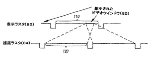
表示フィールド110内(2つの表示vsync信号112の間)では、縮小されたビデオウインドウ80が示されている。破線の対角線は、縮小されたビデオウインドウ80のコンテンツ/タイミングを、捕捉フィールド120(2つのvsync信号114の間)のコンテンツ/タイミングと、マップする。図6Aでは、表示フィールド110は、捕捉フィールド120と奇数と偶数フィールドに関して、同じ極性であると仮定される。
Within the display field 110 (between the two display vsync signals 112), a reduced video window 80 is shown. The dashed diagonal line maps the content / timing of the reduced video window 80 with the content / timing of the capture field 120 (between two vsync signals 114). In FIG. 6A, the
縮小されたビデオウインドウ80は、表示ラスタ82の上部近くにある(例えば、表示フィールド110の左)。表示ラスタ82と捕捉ラスタ84の示された整列により、縮小されたビデオウインドウ80は、このように、全体的に捕捉フィールド120のタイミング内にある。縮小されたビデオウインドウ80が表示されるのが開始されるときに、キャプチャエンジンは、約半分のフィールドコンテンツを捕捉している。縮小されたビデオウインドウ80は小さいので、非常に速く、縮小されたビデオウインドウ80の表示はキャプチャエンジンに”追いつき”そして、キャプチャエンジンを”通過”しさえする(垂直の破線86)。結果は、古いデータが、縮小されたビデオウインドウ80の下部(例えば、右部分)に表示され、これにより、水平のずれ(又は、引き裂き)線を生成する。
The reduced video window 80 is near the top of the display raster 82 (eg, to the left of the display field 110). Due to the illustrated alignment of
図6Bでは、縮小されたビデオウインドウ80は、表示ラスタ82の下部に近い(例えば、表示フィールド110の右端に近い)。しかしながら、図6Aと異なる、表示ラスタ82と捕捉ラスタ84の示された整列により、縮小されたビデオウインドウ80は、図6Aと同じ捕捉ラスタ84のタイミング関係を有する。従って、(再び垂直の破線86での)同じ水平ずれ線問題が発生する。図6Bは、従って、縮小されたビデオウインドウ80の相対的なタイミングは、単純に表示ラスタ82の位置でなく、画像ずれが発生するかどうかに関連することを示す。
In FIG. 6B, the reduced video window 80 is near the bottom of the display raster 82 (eg, near the right edge of the display field 110). However, due to the illustrated alignment of
図6Cでは、縮小されたビデオウインドウ80は、図6Bのように、表示ラスタ82の下部(例えば、表示フィールド110の端の右)に向かう。しかしながら、表示ラスタ82と捕捉ラスタ84の示された整列により、これは、図6Bに示された整列と異なり、縮小されたビデオウインドウ80は、全体的に、捕捉ラスタ84のタイミング内でない。この効果は、縮小されたビデオウインドウ80が、キャプチャエンジンを”通過する”点はないことである。このように、図6Cでは、垂直の破線はなく、そして、画像ずれはテレビジョンモニタ20上には発生しない。
In FIG. 6C, the reduced video window 80 is directed to the bottom of the display raster 82 (eg, to the right of the edge of the display field 110), as in FIG. 6B. However, due to the illustrated alignment of the
図6A−6Cの情報を使用して、一実施例では、システム100のタイミング調整器500は、周期的に、捕捉ラスタ84と表示ラスタ82内の縮小されたビデオウインドウ80のタイミング関係を監視(モニタ)する。必要な場合には、タイミング調整器500は、表示ラスタ82を図6Cに似た捕捉ラスタ84との関係にするために、画素クロック発生器72を修正する。言いかえると、タイミング調整器500は、縮小されたビデオウインドウ80のタイミングが、部分的に又は完全に捕捉フィールド120のアクティブ部分のタイミングの”外側”であるように、表示ラスタ82を、修正する。
6A-6C, in one embodiment, the
例えば、タイミング調整器500が、縮小されたビデオウインドウ80と捕捉ラスタ84のタイミング関係を検出する場合には(図6B参照)、タイミング調整器500は、表示ラスタ82が捕捉ラスタ84に対して僅かに速く又は遅く移動するように、画素クロック70の周波数を変更する。これは、縮小されたビデオウインドウ80と捕捉ラスタ84の相対的なタイミングが、図6Cに示されたのと同様なタイミングに徐々にシフトする。
For example, if the
当業者は、画素クロック発生器72を修正するのを超える、他の技術も表示レートを変更するのに使用されうることを認識する。例えば、水晶発振器60の周波数は、基準としての電圧制御発振器を使用して、同様に修正される。他の例として、他のPLLが基準周波数チェイン内である場合には、それも修正されうる。他の例として、走査線又は画素は、表示ラスタに追加又はそこから除去されうるが、実験はこれは通常は表示にジャンプを発生することが示された。
Those skilled in the art will recognize that other techniques can be used to change the display rate beyond modifying the
一実施例では、タイミング調整器500は、”中間点の”しきい値に対して相対位置を比較することにより、縮小されたビデオウインドウ80と捕捉ラスタ84の望ましいタイミング関係を達成する最も近い経路を見つける。結果に依存して、タイミング調整器500は、PLLレジスタを、画素クロック70の周波数を増加する又は減少させるように調整する。この方法で、タイミング調整器500は、迅速に望ましいタイミングを達成する。観測者に対しては、これは、画像ずれがなくなるまで、水平ずれ線を、ビデオウインドウの最も近いエッジに向かって上方に又は下方に移動するように見える。
In one embodiment, the
一実施例では、画素クロック70の周波数は、画像ずれが、例えば10秒以内に素早く除去されるように、劇的に修正される。カラーバースト信号96は、システム100により正確に発生されるべき画素クロック70に依存することを思い出してほしい。残念ながら、画素クロック70の劇的な調整は、カラーバースト信号96を、テレビジョンモニタ20による正確なカラー表示の範囲の外にする。さらに中程度の調整は、カラーバーストを許容できる範囲に保持しうるが、1分又はそれ以上のような、比較的長い時間の期間の後にのみ画像ずれを除去する。視聴者はテレビジョンモニタ20上の画像ずれを容易く見ることができるので、そのような中程度の調整は望ましくない。
In one embodiment, the frequency of the
従って、一実施例では、タイミング調整器500は、カラーバースト周波数96がテレビジョンモニタ20による正確なカラー表示の範囲内に維持されるように、カラーバースト信号96を補償する。カラーバースト信号96を補償することは、公称値からの画素クロック70の非常に大きな偏差を可能とする。この結果は、カラーバースト96に悪影響なしに、水平ずれ線が、縮小されたビデオウインドウ80の外へ非常に素早く移動される。更に、相対ラスタ位置を周期的にモニタすることにより、画像ずれの後続の発生が予想され且つ避けられる。
Thus, in one embodiment, the
全体的な動作
一実施例に従った、必要なときに捕捉ラスタ84のタイミング関係をモニタし且つ調整する、システム100の動作は、図7にフロー図が示されている。動作の第1段階では、システム100は、画像ずれ問題を避けるために、必要なときに、表示ラスタ82を素早く進め又は遅らせる(ブロック202とダイアモンド204)。この動作は”画像ずれを検出し且つ避ける”と題するセクションと図8,9及び10で、以下に更に詳細に説明する。
Overall Operation The operation of the
一旦、ずれのない表示が達成されると、ずれのない表示は、必要により、表示ラスタ82をゆっくり進め又は遅らせることにより維持される(ブロック206)。
Once a display without deviation is achieved, the display without deviation is maintained by slowly advancing or delaying the
更に、一実施例では、システム100は、ドリフトを連続して分析し、表示ラスタ82のゆっくりした遅れ又は進みとなる画素クロック設定を割当て(ブロック208)、一実施例に従って、基準クロックの不正確さを補償する。これらの動作を、”ずれのない表示と良好なカラーバーストを維持する”と題するセクションと図11、12及び13で、以下に更に詳細に説明する。
Further, in one embodiment, the
画像ずれを検出し且つ避ける
図8では、フロー図は、(図7のブロック202のような)カラーバースト信号96に悪影響を及ぼすことなしに画像ずれを素早く除去する、タイミング調整器500の動作を示すフロー図である。一実施例では、図8の動作は、毎秒(第1のサンプリングレート)のような、周期的に実行される。捕捉ラスタ84と表示ラスタ82の両方に対する現在の走査線数のサンプルは、タイミング調整器500により受信される(ブロック282)。
Detecting and Avoiding Image Shift In FIG. 8, the flow diagram illustrates the operation of the
捕捉及び表示ハードウェアから利用できる場合には、フィールド極性情報も受信される。フィールド情報を含むことは、ずれのない画像表示に受け入れられると考えられる非常に大きな範囲の相対ラスタタイミング位置を提供する。フィールド極性情報がないと、最悪の場合が仮定され、これは、そうでなければ表示ラスタ82の不必要な高速の補正を起こしうる。
Field polarity information is also received if available from the capture and display hardware. Including field information provides a very large range of relative raster timing positions that would be acceptable for a consistent image display. Without field polarity information, the worst case is assumed, which could otherwise cause unnecessary fast correction of the
捕捉処理中に垂直に縮小するときには、捕捉走査線カウントは、実際に捕捉された走査線の数を示しうる。縮小するときには、走査線は、垂直縮小比に従って、落とされる。従って、サンプル値は、入力ビデオ信号38の未スケーリングラスタの走査線カウントに対して、垂直縮小比の逆数により減じられうる。
When shrinking vertically during the capture process, the capture scan line count may indicate the number of scan lines actually captured. When shrinking, the scan line is dropped according to the vertical reduction ratio. Thus, the sample value can be reduced by the inverse of the vertical reduction ratio relative to the unscaled raster scan line count of the
例えば、2:1の比で縮小するときには、入力ビデオ信号38がアクティブビデオの100番目の走査線に達するときに、サンプルされた値は、”50”を示しうる。タイミング調整器500は、縮小比により捕捉走査線サンプル値を乗算することにより補償し、未スケーリングの入力ビデオ信号38の現在のラスタタイミングを示す値となる。
For example, when scaling down at a 2: 1 ratio, when the
同様に、表示処理で拡大するときには、捕捉されたビデオの走査線は複製され、タイミング調整器500による表示走査線カウントの補償となる。当業者は、捕捉ラスタ84と表示ラスタ82の他の形式の補償は、この2つの間のタイミング関係を測定する意味のある方法で補償されることが可能な値を発生しうることは、認識する。
Similarly, when zooming in the display process, the captured video scan lines are duplicated to compensate for the display scan line count by the
例えば、表示ハードウェアが、半分の走査線に関する表示ラスタ位置を示し、一方、捕捉ハードウェアが、全体の走査線に関する捕捉位置を示しうる。他の例としては、表示ハードウェアが垂直帰線消去期間中に発生するインアクティブなビデオ走査線を含むように表示ラスタを示し、一方、捕捉ハードウェアは、アクティブに捕捉された走査線のカウントのみを示しうる。 For example, the display hardware may indicate the display raster position for half the scan lines, while the capture hardware may indicate the capture position for the entire scan line. As another example, a display raster is shown so that the display hardware includes inactive video scan lines that occur during the vertical blanking interval, while the capture hardware counts the actively captured scan lines. Can only show.
他の例としては、表示ハードウェアは、一時に全フレームの、順次走査画像を表示し、そして、それに従って、表示走査線を示し、一方、捕捉ハードウェアは、インターレースされたラスタの単一のフィールド内で捕捉されたインターレースされた走査線のカウントを示しうる。そのような指示は、同等にするために、当業者には明らかな、適する補償を必要とする。 As another example, the display hardware displays a progressive scan image, all frames at a time, and accordingly displays display scan lines, while the capture hardware is a single interlaced raster. A count of interlaced scan lines captured in the field may be indicated. Such instructions require suitable compensation, which will be apparent to those skilled in the art, in order to be equivalent.
捕捉ラスタ84は、”デッド”ゾーンを有し、これは、本質的に、捕捉ラスタ84の垂直帰線消去期間であり、その間に走査線が捕捉されない。この時間の間は、捕捉ハードウェアは、捕捉ラスタ84の正確な位置を決定する機構を提供しない。このゾーン内での排他的な繰返しのサンプリングを避けるために、一実施例では、捕捉ラスタ84と表示ラスタ82をサンプリングする期間は、フィールド時間の正確な倍数ではない。
The
図8に戻ると、一実施例では、タイミング調整器500は、表示ラスタ82内で縮小されたビデオウインドウ80の上部又は下部エッジを示す情報を受信する。この情報とそして、表示ラスタの現在のサンプルと捕捉ラスタタイミング位置から、タイミング調整器500は、捕捉ラスタ84に対する縮小されたビデオウインドウ80のタイミング関係を計算する(ブロック284)。
Returning to FIG. 8, in one embodiment, the
この情報から、図6Aと6Bの垂直線86により示されているように、画像ずれが発生するかどうかを決定することが可能である。タイミング調整器500は、図6Aと6Bに示されたように、縮小されたビデオウインドウ80が、捕捉フィールド120の開始後に開始しそして、捕捉フィールド120の終了の前に終了するかどうかを決定する(ダイアモンド286)。当業者は、縮小されたビデオ80の上部と下部のエッジに関する情報が異なる形式で受信され得、そして、異なる形式で捕捉されたビデオと比較されうることを、認識する。
From this information, it is possible to determine whether image misalignment occurs, as indicated by the
例えば、上部エッジ座標と高さが示され又は、代わりに、上部エッジと下部エッジについての別の座標が示されうる。当業者は、上部及び下部エッジに関する情報は、順次走査ラスタ内の位置を示す形式で受信され、一方インターレースラスタが表示されることを、認識する。そのような場合には、タイミング調整器500は、分析中に情報を変換しうる。
For example, the upper edge coordinates and height can be shown, or alternatively, different coordinates for the upper and lower edges can be shown. Those skilled in the art will recognize that information about the upper and lower edges is received in a form that indicates the position in the progressive scan raster, while an interlaced raster is displayed. In such cases, the
縮小されたビデオウインドウが、捕捉ラスタ84のタイミング内にある場合(ダイアモンド286の”yes”側)には、一実施例に従って、システム100は素早く画像ずれを表示ラスタ82から移動する(ブロック288)。この動作は、図9のフロー図に示されている。
If the reduced video window is within the timing of capture raster 84 (the “yes” side of diamond 286),
代わりに、縮小されたビデオウインドウが捕捉ラスタ84のタイミング内にない場合(ダイアモンド286の”no”側)には、一実施例に従って、システム100は、ゆっくりドリフトするように、画素クロック70とカラーバースト発生器102を設定する(ブロック290)。この動作は、図10のフロー図に示されている。
Alternatively, if the reduced video window is not within the timing of the capture raster 84 (the “no” side of the diamond 286), according to one embodiment, the
図9では、フロー図は、表示ラスタ82から画像ずれを素早く移動するための、一実施例に従った、タイミング調整器500の動作を示す。一実施例では、動作は、約200msecごとに実行される(第2のサンプリングレート)。タイミング調整器500は、最初に、表示ラスタ82を既に素早く進めているか又は遅らせているかどうかを決定する(ダイアモンド302)。そうである場合には、タイミング調整器500により、更なる動作はとられない。
In FIG. 9, a flow diagram illustrates the operation of the
そうでない場合には、タイミング調整器500により、表示ラスタ82を速くするか又は遅くするかのいずれが、縮小されたビデオウインドウ80から画像ずれ線86を移動する(図6Aと6B参照)、最も早い方法を提供するかに関する決定がなされる。タイミング調整器500は、縮小されたビデオウインドウ80の垂直の中心のタイミングを、捕捉されたビデオラスタ84の垂直中心のタイミングと比較する(ダイアモンド304)。縮小されたビデオウインドウ80の中心が捕捉されたビデオラスタ84の中心よりも後である場合(ダイアモンド304の”yes”側)には、タイミング調整器500は、画素クロック70の周波数を減少させる。それにより、これは、表示ラスタ82を遅らせ、画像ずれ線86を縮小されたビデオウインドウ80の下部に向かって移動する(ブロック306)。
Otherwise, the
逆に、縮小されたビデオウインドウ80の中心が、捕捉されたビデオラスタ84の中心よりも早い場合(ダイアモンド304の”no”側)には、タイミング調整器500は、画素クロック70の周波数を増加させ、それにより、表示ラスタ82を進め、画像ずれ線86を縮小されたビデオウインドウ80の上部に向かって移動する(ブロック308)。
Conversely, if the center of the reduced video window 80 is earlier than the center of the captured video raster 84 (the “no” side of the diamond 304), the
画像ずれを避けるために、一実施例に従って、縮小されたビデオウインドウ80の1つのエッジのみを、捕捉ラスタ84のタイミングの外側へ、移動すれば十分である。タイミング調整器500は、そのようなタイミングのしきい値で正確に、ずれ線の高速な移動を停止し、そして、すぐにずれのない表示を達成する。
To avoid image misalignment, it is sufficient to move only one edge of the reduced video window 80 out of the timing of the
一実施例では、しかしながら、特別なヒステリシスゾーンが設けられ、そこでは、高速な移動が、ビデオウインドウエッジが捕捉ラスタ84のタイミングを過ぎる幾つかの走査線(例えば、10)まで、継続する。ゆっくりしたラスタ移動に戻るときには(以下を参照)、タイミング調整器500は水晶発振器66の特性を詳しく知る必要はない。自己較正が発生する前に(以下を参照)、何のPLL設定が表示ラスタ82をゆっくり進めるか又は遅らせるかは、正確に知られない。ヒステリシスゾーンは、ラスタ移動を、タイミング調整器500がそれ自身を水晶発振器66の特性に較正するまで、しばらくの間、高速な移動の反対方向へ進めることを許す。
In one embodiment, however, a special hysteresis zone is provided, where fast movement continues until several scan lines (eg, 10) where the video window edge passes the
表示ラスタ82を能動的に移動するときに、タイミング調整器500は、一実施例に従って、第1のサンプリングレートよりも更に頻繁にラスタ位置をサンプルする(図8のブロック282参照)。一実施例では、加速されたサンプリングレート(第2のサンプリングレート)は、望ましいラスタタイミングが達成された後に、オーバーシュートを最小化する。一旦、ずれのないラスタタミングが達成されると、タイミング調整器500は、第1のサンプリングレートに戻る。一実施例では、第1のサンプリングレートは、フィールド時間の正確な倍数ではない。より短いサンプリング期間(第2のサンプリングレート)は、より長いサンプリング期間(第1のサンプリングレート)の約5倍の頻度である。
When actively moving the
一実施例では、タイミング調整器500は、分子、分母、及び乗算値を含む、予め定められたPLLパラメータのテーブルを使用する。テーブルに含まれるのは、表示ラスタ82の高速な進みを発生する予め定められたエントリ、表示ラスタ82の高速な遅れを発生する予め定められたエントリ、表示ラスタ82のゆっくりした移動を発生する予め定められたエントリである。
In one embodiment, the
一実施例では、ゆっくりした動きの正確な性質は、タイミング調整器500がラスタ移動対入力ビデオ信号を較正するまで知られない(以下を参照)。非常に正確な基準クロック周波数が与えられた正確な所定のPLL設定については、水晶発振器66の公差は、セットトップボックス100の一例では表示ラスタ82のゆっくりした進みを生じ、一方、他の例では、表示ラスタ82のゆっくりした遅れを生じる。
In one embodiment, the exact nature of the slow motion is not known until the
図9に戻ると、画素クロック70を調整した後に、タイミング調整器500は、カラーバースト信号96(図3B参照)が適切に発生されるように、カラーバースト発生器102を調整する(ブロック310)。一実施例では、予め定められたPLLパラメータのテーブルは、較正データと結合され且つカラーバースト調整がそれから計算される周波数誤差情報も含む。
Returning to FIG. 9, after adjusting the
一実施例では、タイミング調整器500は、画素クロック発生器72を新たなパラメータに再ロックしながら、視覚的なアーティファクトを最小化するために、表示ラスタ82の垂直帰線消去期間(VBI)中に、画素クロック発生器72とカラーバースト発生器102レジスタセットを変更する。一実施例では、画素クロック発生器72とカラーバースト発生器102は、割り込みサービスルーチンで調整され、これは、垂直帰線消去期間でグラフィックス/オーディオコントローラ14により発生されたハードウェア割り込みに応答して実行される。
In one embodiment, the
図8に戻ると、システム100は、図9の動作に従って、最も早い方向へビデオウインドウから画像ずれを移動する(ブロック288)。
Returning to FIG. 8, the
一旦、タイミング調整器500が、縮小されたビデオウインドウが捕捉ラスタ84のタイミング内には完全にはなく(第1モンド286の”no”側)、そして、従って、画像ずれを示さないことを決定すると、タイミング調整器500は、表示ラスタ82がゆっくりドリフトするように、画素クロック70とカラーバースト発生器102を設定する(ブロック290)。これらの動作は、図10に記載されている。
Once the
最初に、実施例に従って、タイミング調整器500は、ずれを高速に移動することの残り効果として、表示ラスタ82を高速に進めているか又は遅らせているかを決定する(ダイアモンド322)。高速に進めている場合には、画素クロック70は表示ラスタ82をゆっくり進めるように調整される(ブロック326)。高速に遅らせている場合には、画素クロック70は表示ラスタ82をゆっくり遅らせるように調整される(ブロック328)。
Initially, according to the embodiment, the
高速に進めるか又は高速に遅らせるかのいずれでもない場合には、処理の先頭で画像はずれがなくそして、そらすことは必要ない。この場合には、画素クロック70はそのまま残り(ブロック324)、現在の方向へ、表示ラスタのゆっくりしたドリフトを続ける。
If it is neither fast forward nor slow fast, there is no misalignment at the beginning of the process and there is no need to deflect it. In this case, the
一旦、画素クロック70を調整するかどうかの決定がなされると、カラーバースト発生器102は、一実施例に従って、公称設定に調整される(ブロック330)。
Once a determination is made whether to adjust the
許容されるタイミング範囲内でゆっくりドリフトするときには、タイミング調整器500は、カラーバースト発生器102を公称の省略時設定へ設定し、非常に正確な水晶発振器66を仮定する。省略時設定は、画素クロックPLL設定が変更されても維持され、それにより、カラーバースト周波数を変更する。たとえ、カラーバースト周波数変更が、それ自身で望ましくなくても、カラーバースト発生器102の省略時設定は、表示信号42の水平同期信号へのカラーバーストの位相ロックを維持する。一実施例では、カラーバーストを水平同期信号へロックすることは、”クローリングドット”のような視覚的な異常を最小化する。以下に記載の処理は、TVモニタ20による連続する表示のために、カラーバースト信号を受け入れられる許容範囲内に保持する。
When slowly drifting within the allowed timing range, the
このように、ゆっくりドリフトさせるために、画素クロック70とカラーバースト発生器102を設定する動作は、完了する。
In this way, the operation of setting the
ずれのない表示と良好なカラーバースト周波数を維持する
図7に戻ると、画像ずれ問題を解決した後に、システム100は、ずれの無い表示を維持する(ダイアモンド204の”no”側を参照)。一旦、ずれの無いラスタタイミング位置が初期的に達成又は検出されると、タイミング調整器500は、表示ラスタ82にラスタタイミング位置の許容範囲内でゆっくりドリフトするようにすることにより、ずれの無い状態を維持する。一実施例では、タイミング調整器500は、進行中の周期に基づいて、捕捉ラスタ84、表示ラスタ82及び縮小されたビデオウインドウ80の位置をモニタする。
Maintaining no misalignment and good color burst frequency Returning to FIG. 7, after resolving the image misalignment problem, the
モニタされている情報から、タイミング調整器500は、ずれの無い表示のために、許容できるラスタタイミング関係を維持するために、必要により、周波数比を僅かに高く又は低く調整するように、画素クロック発生器72を調整する。一実施例では、調整は、表示ラスタ82を、捕捉ラスタ84に対してゆっくり交互に進める又は遅らせるようにする。ラスタタイミング位置がずれの無い表示のために許容できるタイミング範囲に達するときに、タイミング調整器500は、ドリフトの方向を逆にする。
From the information being monitored, the
一実施例に従った、ずれの無い表示を維持するタイミング調整器500の動作は、図11のフロー図に示されている。タイミング調整器は、有効ならば、捕捉ラスタ84及び表示ラスタ82の極性とともに、捕捉及び表示走査線番号をサンプルする(ブロック342)。この情報を使用して、タイミング調整器500は、捕捉ラスタ84に対して縮小されたビデオウインドウのタイミング関係を計算する(ブロック344)。
The operation of the
タイミング関係に依存して、タイミング調整器500は、表示ラスタ82がゆっくり遅れるように(ブロック350)、表示ラスタ82をゆっくり進めるように(ブロック352)又は、画素クロック70がそのままであるように(ブロック348)、画素クロック70を調整する。
Depending on the timing relationship, the
捕捉ラスタ84と縮小されたビデオウインドウ80の相対的なタイミング位置をモニタしながら、タイミング調整器500は、現在のPLL設定のために、捕捉ラスタ84に対する表示ラスタ82のドリフトの全体的なレートも、モニタする。較正に基づいて、タイミング調整器500は、水晶発振器66の公差から生じるラスタドリフトとカラーバーストの不正確さの両方を最小化する、新たなPLL設定を選択しうる。
While monitoring the relative timing positions of the
上述のように、一実施例では、画素クロック発生器72周波数の各ステップは、分子、分母及び乗算値の幾つかの組の1つである。これらの値は、画素クロック発生器72についての密に配置された離散周波数の可能性のグループを構成する。その値は、上述のように、PLL設定のテーブルに示されている。一実施例では、捕捉ラスタ84と表示ラスタ82の間の最小の相対的な移動を生じるPLL値は、水晶発振器66が非常に正確であると仮定すると、画素クロック発生器72についての初期省略時値であると考えられる。
As described above, in one embodiment, each step of the
タイミング調整器500は、テーブル内の2つ又は3つの隣接PLL値の組みのグループを選択する。一実施例では、3つのPLL値の組、上方設定、中間設定及び下方設定が、選択され、中間設定は初期省略時設定として、指定される。上方設定は、中間と下方設定に対してより高い周波数値を含む。最初に、ずれの無い表示の維持を開始するときに、タイミング調整器500は、ゆっくり表示ラスタ82を進める上方設定値又は、ゆっくり表示ラスタ82を遅らせる下方設定値を使用する。
The
一実施例では、PLL設定のテーブルは、各設定の周波数誤差対理想的な画素クロック周波数に関する情報を含み、非常に正確な水晶発振器66を仮定する。当業者は、この情報は多くの形式をとり、そして、表示ラスタ82対入力ビデオ信号38の捕捉ラスタ84の予想されるドリフトレートに対応することを認識する。
In one embodiment, the PLL settings table contains information about the frequency error of each setting versus the ideal pixel clock frequency, assuming a very
ずれの無い表示を維持するためにゆっくりドリフトしながら、タイミング調整器500は、周期的に、ドリフトの実際のレートをモニタしそして推定する。タイミング調整器500は、更に、テーブル内の周波数誤差情報に基づいて、ドリフトのこの推定されたレートを最もよく補償するPLL設定について検索する。獲得されたPLL設定は、新たな省略時設定となりそして、タイミング調整器500は、表示ラスタ82を進める又は遅らせるために、その上方又は下方値設定を使用する。
The
一実施例では、タイミング調整器500は、省略時設定が、表示ラスタ82を明確に進める(又は、逆に、遅らせる)ことを決定し得る。この場合には、省略時設定は、タイミング調整器500がそれで表示ラスタ82を進める(又は、逆に、遅らせる)設定としても働く。この決定は、推定された実際のドリフトを補償する新たな省略時画素クロック発生器72設定を使用するとき期待される周波数誤差に基づいてなされる。
In one embodiment, the
画素クロック発生器72は、離散的な周波数を発生するので、正確な画素クロック70を発生する最も近い一致は、非常に正確な画素クロック70を発生しないようである。ある場合には、最も近い一致の推定された周波数誤差は、ドリフトの実際のレートの測定値の予め定められた不確定性を覆うほど十分に大きい。当業者は、これらの不確定性は、モニタリング期間の正確な時間期間、捕捉及び表示ラスタの測定値の量子化(特に、縮小中のラインドロッピングによ量子化が悪化されうる、捕捉ラスタ)、及び同様な関係の不確定性から生じることを認識する。
Since
タイミング調整器500の動作は、一実施例に従って、ドリフトの実際のレートをモニタしそして2つ又は3つのPLL設定のグループを選択するときに、図12のフロー図で示されている。一実施例では、図12の動作は毎秒1回実行されうる。
The operation of the
捕捉ラスタ84の現在の走査線と表示ラスタ82の現在の走査線が、引き出される(ブロック362)。この動作は、画像ずれの防止のために捕捉ラスタ84と表示ラスタ82をモニタするときと同じ動作である(図8のブロック282参照)。ハードウェアから読まれた実際の値は、捕捉及び表示値が比較されるために、上述のように、補償が必要である。引き出された走査線の間の差が計算される(ブロック364)。この情報、捕捉ラスタ84と表示ラスタ82の間のタイミング関係は、タイミング調整器500によりメモリ16内に又は、グラフィックス/オーディオコントローラ14内のローカルメモリに記憶される。
The current scan line of the
一実施例では、メモリ16に記憶されている、前の位置の差が引き出されそして、差の差の結果を生じるために、現在の位置の差と比較され(ブロック366)、これは、捕捉ラスタ84に対する表示ラスタ82のドリフトレートを表す。差の差の計算は、そして、蓄積されそして、前の差の差の計算と共に記憶される(ブロック368)。繰返しカウンタ(ブロック370)は、蓄積されているサンプルの数を示す。
In one embodiment, the previous position difference stored in
一実施例では、複数の位置の差が記憶され、各々は幾つかのサンプリング/モニタリング期間にわたる。これは、複数の差の差の計算がなされるのを可能とする。一実施例では、4つの位置の差が記憶され、4サンプリング/モニタリング期間にわたる。これは、ドリフトレートの推定に更なる精度を供給する。 In one embodiment, multiple position differences are stored, each over several sampling / monitoring periods. This allows a difference calculation of multiple differences to be made. In one embodiment, four position differences are stored and span four sampling / monitoring periods. This provides additional accuracy for drift rate estimation.
一実施例では、十分な数の計算が蓄積されたかどうかを決定するために、チェックがなされる(ダイアモンド372)。一実施例では、8サンプルが十分であると考えられる。一旦、十分な数のサンプルが利用できると、画素クロック70が変更されうるように、データが分析される(ブロック374)。図12の動作は、毎秒1回のように、周期的に繰返される。
In one embodiment, a check is made (diamond 372) to determine if a sufficient number of calculations have been accumulated. In one example, 8 samples are considered sufficient. Once a sufficient number of samples are available, the data is analyzed so that the
蓄積されたサンプルの分析(図12のブロック374)は、図13のように、タイミング調整器500により実行される。変化の平均レートが、計算される(ブロック382)。変化の平均レートは、捕捉ラスタ84と表示ラスタ82の、位置の差又はドリフトの1次微分に等しい。一実施例では、メモリ16又はローカルメモリに記憶された、蓄積された差の差は、既にタイミング調整器500により記憶された、繰返しカウント数により除算される(図12のブロック370参照)。
The analysis of the accumulated sample (block 374 of FIG. 12) is performed by the
一実施例では、タイミング調整器500はそして、ドリフト推定値を、実際の画素周波数対ドリフトのない画素クロック70の理想周波数の誤差の推定値に、変換する(ブロック384)。例えば、一実施例では、ドリフト推定値は、4つのモニタリング期間をわたり半分の走査線に関して計算され、ここで、各モニタリング期間は1010msecの継続時間である。
In one embodiment, the
ここで、表示ラスタ82は、フェーズアルターネートライン(PAL)であり、そして、”正方形” 画素を使用し、例えば、表示ラスタ82についての画素クロック周波数は、一実施例では、29.500MHzであり、実際の画素表示レートは14.750MHzである。これらの特性で、走査線当り944画素(768アクティブ/可視及び176インアクティブ/ブランクの画素)又は、半走査線当り944画素ロック期間がある。以下の式は、”HSL”は”半走査線”を意味し、ドリフトレート推定値をヘルツに変換する:

一実施例では、タイミング調整器500は、現在のPLL設定についてのテーブル内の周波数誤差情報を考慮する。周波数誤差は、非常に正確な水晶発振器66で、PLL設定についてHzで誤差を示すことを思い出してほしい。例えば、あるPLL設定が、正確に24.576000MHzの水晶発振器66を使用して、29.500384MHzの周波数を生成する場合には、テーブルは値384を含む。画素クロック70の誤差は、次のように計算される:
最も近い一致についての検索では、タイミング調整器500は、−ErrorInHzと、新たな省略時画素クロック発生器72についてのテーブルエントリ内の誤差値の間の差の絶対値を計算する。この値が、予め定められたしきい値よりも大きい場合には、周期的なラスタサンプリング内の不確定性をおおい、そして、新たな省略時画素クロック発生器72エントリが、表示ラスタ82を明確に進める又は遅らせると考えられうる(ダイアモンド388)。
In the search for the closest match, the
一実施例では、タイミング調整器500は、PLL設定を、ずれの無い表示のための捕捉ラスタ84と表示ラスタ82の間の受け入れられるタイミング関係を維持するときに使用される、ゆっくり進める、省略時、及びゆっくり遅らせる設定として割当てる。
In one embodiment, the
省略時設定が明確に表示ラスタ82を進める場合には、省略時及びゆっくり進める設定は同じである(ブロック390)。他の端では、省略時設定が明確に表示ラスタ82を遅らせる場合には、省略時及びゆっくり遅らせる設定は同じである(ブロック400)。
If the default setting clearly advances the
捕捉ラスタ84と表示ラスタ82の間のドリフトを最小化するために画素クロック70を調整することにより、画素クロック発生器72は、合理的に正確な画素クロック70を発生しうる(ブロック402)。図12と13の方法を使用して、画素クロック70は本質的に入力ビデオ信号38を参照する。システム100は代わりにテレビジョンモニタ20上に表示される画像の完全性を維持する。
By adjusting the
特に、コストに敏感なセットトップボックスについては、タイミング調整器500は、システム100の使用できる動作のより広い温度範囲を許すと共に、水晶発振器66のより広い公差と、そして、それゆえに、よりやすい発振器部品コストを可能とする。
In particular, for cost-sensitive set-top boxes, the
図12と13に示された処理は、システム100に有効な入力ビデオ信号38が受信される限り継続する。入力ビデオ信号38についてのソースが変更の時又はビデオキャプチャ動作のない期間の後にビデオキャプチャを開始又は再開始するときのような、平均化処理をリセットした後に、1次微分の正確な表現を保証するために毎回十分な数のサンプルがとられる。一実施例では、12サンプルが十分な数と考えられる。
The process illustrated in FIGS. 12 and 13 continues as long as a valid
有効な入力ビデオ信号38がなくそして、タイミング調整器500が”最も良い”省略時PLL設定を選択する機会を有しない場合には、予め定められた省略時PLL設定がタイミング調整器500により使用される。一実施例では、タイミング調整器500が新たな省略時PLL設定を選択するのに十分長く、有効なビデオ信号が存在する場合には、新たな省略時設定は、有効な入力ビデオ信号38が失われる場合及びときに、使用される。これは、ビデオが存在しないときでさえも、正確なカラーバースト信号についての最良の推定値を保存する。
If there is no valid
本発明を制限された数の実施例に関して説明したが、当業者は、それからの多くの修正と変形があることは、理解しよう。添付の請求項は、そのような修正と変形を、本発明の精神と範囲内であるようにカバーすることが意図されている。 Although the present invention has been described with respect to a limited number of embodiments, those skilled in the art will appreciate that there are many modifications and variations therefrom. The appended claims are intended to cover such modifications and variations as fall within the spirit and scope of the invention.
Claims (25)
ビデオウインドウが完全に捕捉ラスタのタイミング内ではない場合に、表示ラスタがドリフトするように画素クロックを設定することによって、ビデオウインドウのずれを避けるために画素クロックを調整し、
前記ビデオウインドウが前記捕捉ラスタのタイミング内にある場合には、前記ビデオウインドウが完全に前記捕捉ラスタのタイミング内ではない場合の表示ラスタのドリフトに対して素早く、ずれを前記ビデオウインドウから移動させる、方法。Determine the timing relationship between the video window and the capture raster, the video window is in the display raster,
Adjust the pixel clock to avoid video window drift by setting the pixel clock so that the display raster drifts when the video window is not completely within the timing of the capture raster ,
When said video window is in the timing of the acquisition raster quickly relative drift of the display raster when the video window is not within the time of completely the acquisition raster Before moving the shift from the video window ,Method.
ビデオウインドウから画像ずれを移動することを、
更に有する、請求項1に記載の方法。Determine that the video window is within the timing of the capture raster,
Move the image shift from the video window,
The method of claim 1 further comprising:
更に有する、請求項1に記載の方法。Setting the color burst generator to phase lock within the display raster,
The method of claim 1 further comprising:
ビデオウインドウが捕捉されたラスタよりも遅いことを決定し、
表示ラスタを遅らせるように画素クロックを調整することを、
有する、請求項2に記載の方法。Moving the image shift from the video window further
Determine that the video window is slower than the captured raster,
Adjusting the pixel clock to delay the display raster,
The method of claim 2 comprising:
更に有する、請求項5に記載の方法。Adjusting the color burst generator to maintain the image visible on the display raster,
6. The method of claim 5, further comprising:
その周波数誤差情報を使用してカラーバースト調整を計算することを、
更に有する、請求項6に記載の方法。Search frequency error information from a table of predetermined phase lock loop parameters,
Using that frequency error information to calculate the color burst adjustment,
The method of claim 6 further comprising:
ビデオウインドウが捕捉ラスタよりも早いことを決定し、
表示ラスタを進めるために画素クロックを調整し、
表示ラスタ上に見える画像を維持するためにカラーバースト発生器を調整することを、
有する、請求項2に記載の方法。Moving the image shift from the video window further
Determine that the video window is faster than the capture raster,
Adjust the pixel clock to advance the display raster,
Adjusting the color burst generator to maintain the image visible on the display raster,
The method of claim 2 comprising:
画素クロックが表示ラスタを進めることを決定し、
表示ラスタを進めるように画素クロックを設定することを、
有する、請求項1に記載の方法。Setting the pixel clock so that the display raster drifts further
The pixel clock decides to advance the display raster,
Setting the pixel clock to advance the display raster,
The method of claim 1, comprising:
画素クロックが表示ラスタを遅らせていることを決定し、
表示ラスタを遅らせるように画素クロックを設定することを、
有する、請求項1に記載の方法。Setting the pixel clock so that the display raster drifts further
Determine that the pixel clock is delaying the display raster,
Set the pixel clock to delay the display raster,
The method of claim 1, comprising:
捕捉ラスタフィールド極性を決定し、
表示ラスタフィールド極性を決定することを、
有する、請求項12に記載の方法。Furthermore,
Determine the capture raster field polarity,
To determine the display raster field polarity,
13. The method according to claim 12, comprising:
捕捉ラスタと表示ラスタを周期的にモニタすることを、
有する、請求項1に記載の方法。Determining the timing relationship between the video window and the capture raster is further
Periodically monitoring the capture and display rasters,
The method of claim 1, comprising:
垂直帰線消去期間を識別し、
画素クロックを調整する割り込みサービスルーチンを呼出すことを、
有する、請求項1に記載の方法。Adjusting the pixel clock to avoid video window drift further
Identify the vertical blanking interval,
Calling the interrupt service routine to adjust the pixel clock,
The method of claim 1, comprising:
ビデオウインドウが捕捉ラスタのタイミング内ではない場合に、表示ラスタがドリフトするように、ビデオウインドウのずれを避けるために画素クロックを調整し、
前記ビデオウインドウが前記捕捉ラスタのタイミング内にある場合には、前記ビデオウインドウが完全に前記捕捉ラスタのタイミング内ではない場合の表示ラスタのドリフトに対して素早く、ずれを前記ビデオウインドウから移動させる、
ことをシステムに、実行された場合に可能とするプログラムを記憶するコンピュータ読み取り可能な記憶媒体。Calculate the timing relationship between the video window and the capture raster, the video window is in the display raster,
Adjust the pixel clock to avoid video window drift so that the display raster drifts when the video window is not within the capture raster timing ,
When said video window is in the timing of the acquisition raster quickly relative drift of the display raster when the video window is not within the time of completely the acquisition raster Before moving the shift from the video window ,
A computer-readable storage medium for storing a program that enables the system to execute the operation.
ビデオウインドウは捕捉ラスタのタイミング内であることを決定し、
ビデオウインドウから画像のずれを移動する、
ことを可能とする、請求項17に記載のコンピュータ読み取り可能な記憶媒体。Said instructions further to the system:
Determine that the video window is within the timing of the capture raster,
Move image displacement from the video window,
The computer-readable storage medium according to claim 17, which makes it possible.
カラーバースト発生器を表示ラスタに位相ロックさせるように設定する、
ことを可能とする、請求項17に記載のコンピュータ読み取り可能な記憶媒体。The instructions further instruct the system:
Set the color burst generator to phase lock to the display raster,
The computer-readable storage medium according to claim 17, which makes it possible.
カラーバースト発生器を予め定められた公称設定に設定する、
ことを可能とする、請求項19に記載のコンピュータ読み取り可能な記憶媒体。The instructions further instruct the system:
Set the color burst generator to a predetermined nominal setting;
20. A computer readable storage medium according to claim 19, which makes it possible.
ビデオウインドウが捕捉ラスタよりも遅いことを決定し
表示ラスタを遅らせるように画素クロックを調整する、
ことを可能とする、請求項17に記載のコンピュータ読み取り可能な記憶媒体。The instructions further instruct the system:
Determine that the video window is slower than the capture raster and adjust the pixel clock to delay the display raster,
The computer-readable storage medium according to claim 17, which makes it possible.
表示ラスタ上に見える画像を維持するためにカラーバースト発生器を調整する、
ことを可能とする、請求項21に記載のコンピュータ読み取り可能な記憶媒体。The instructions further instruct the system:
Adjust the color burst generator to keep the image visible on the display raster,
The computer-readable storage medium of claim 21, wherein:
ビデオウインドウが捕捉ラスタよりも前であることを決定し、
表示ラスタを進めるために画素クロックを調整し、
表示ラスタ上に見える画像を維持するためにカラーバースト発生器を調整する、
ことを可能とする、請求項17に記載のコンピュータ読み取り可能な記憶媒体。The instructions further instruct the system:
Determine that the video window is before the capture raster,
Adjust the pixel clock to advance the display raster,
Adjust the color burst generator to keep the image visible on the display raster,
The computer-readable storage medium according to claim 17, which makes it possible.
画素クロックが表示ラスタを進めることを決定し、
表示ラスタを進めるように画素クロックを設定する、
ことを可能とする、請求項17に記載のコンピュータ読み取り可能な記憶媒体。The instructions further instruct the system:
The pixel clock decides to advance the display raster,
Set the pixel clock to advance the display raster,
The computer-readable storage medium according to claim 17, which makes it possible.
画素クロックが表示ラスタを遅らせていることを決定し、
表示ラスタを遅らせるように画素クロックを設定する、
ことを可能とする、請求項17に記載のコンピュータ読み取り可能な記憶媒体。The instructions further instruct the system:
Determine that the pixel clock is delaying the display raster,
Set the pixel clock to delay the display raster,
The computer-readable storage medium according to claim 17, which makes it possible.
Applications Claiming Priority (2)
| Application Number | Priority Date | Filing Date | Title |
|---|---|---|---|
| US09/881,304 US6943844B2 (en) | 2001-06-13 | 2001-06-13 | Adjusting pixel clock |
| PCT/US2002/012172 WO2002102063A1 (en) | 2001-06-13 | 2002-04-19 | Adjusting pixel clock |
Publications (2)
| Publication Number | Publication Date |
|---|---|
| JP2004530167A JP2004530167A (en) | 2004-09-30 |
| JP4072120B2 true JP4072120B2 (en) | 2008-04-09 |
Family
ID=25378202
Family Applications (1)
| Application Number | Title | Priority Date | Filing Date |
|---|---|---|---|
| JP2003504667A Expired - Fee Related JP4072120B2 (en) | 2001-06-13 | 2002-04-19 | How to adjust the pixel clock |
Country Status (7)
| Country | Link |
|---|---|
| US (2) | US6943844B2 (en) |
| EP (1) | EP1405507A1 (en) |
| JP (1) | JP4072120B2 (en) |
| KR (1) | KR100647167B1 (en) |
| CN (1) | CN100403780C (en) |
| TW (1) | TW588550B (en) |
| WO (1) | WO2002102063A1 (en) |
Families Citing this family (32)
| Publication number | Priority date | Publication date | Assignee | Title |
|---|---|---|---|---|
| US6943844B2 (en) * | 2001-06-13 | 2005-09-13 | Intel Corporation | Adjusting pixel clock |
| US7046254B2 (en) * | 2002-01-28 | 2006-05-16 | International Business Machines Corporation | Displaying transparent resource aids |
| US7136109B2 (en) * | 2002-03-22 | 2006-11-14 | Pelco | Self-adjusting pixel clock and method therefor |
| US7120814B2 (en) * | 2003-06-30 | 2006-10-10 | Raytheon Company | System and method for aligning signals in multiple clock systems |
| KR100580176B1 (en) * | 2003-09-17 | 2006-05-15 | 삼성전자주식회사 | Display Synchronization Signal Generator in Digital Broadcasting Receiving System |
| KR100580177B1 (en) * | 2003-09-22 | 2006-05-15 | 삼성전자주식회사 | Apparatus and decoder for display synchronization signal generation in digital broadcasting reception system and method thereof |
| US8146497B2 (en) * | 2004-05-04 | 2012-04-03 | Sys Tec S.R.L. | Method and machine for aligning flexographic printing plates on printing cylinders |
| US7827424B2 (en) * | 2004-07-29 | 2010-11-02 | Ati Technologies Ulc | Dynamic clock control circuit and method |
| JP2006094415A (en) * | 2004-09-27 | 2006-04-06 | Toshiba Corp | Video image apparatus and video image streaming method |
| TWI244342B (en) * | 2004-10-12 | 2005-11-21 | Beyond Innovation Tech Co Ltd | Method and apparatus for image timing convert |
| US7461939B2 (en) * | 2004-11-19 | 2008-12-09 | Hewlett-Packard Development Company, L.P. | Automatic zoom for screen fitting |
| US20060150071A1 (en) * | 2005-01-05 | 2006-07-06 | Microsoft Corporation | Software-based video rendering |
| US7519845B2 (en) * | 2005-01-05 | 2009-04-14 | Microsoft Corporation | Software-based audio rendering |
| KR100622351B1 (en) * | 2005-01-07 | 2006-09-19 | 삼성전자주식회사 | Video pixel clock generation method and video pixel clock generation device using same |
| KR100706625B1 (en) * | 2005-01-18 | 2007-04-11 | 삼성전자주식회사 | Video pixel clock generation method and video pixel clock generation device using same |
| US7800621B2 (en) * | 2005-05-16 | 2010-09-21 | Ati Technologies Inc. | Apparatus and methods for control of a memory controller |
| JP5161426B2 (en) * | 2006-01-31 | 2013-03-13 | 株式会社ジャパンディスプレイセントラル | Display control device |
| US20080062311A1 (en) * | 2006-09-13 | 2008-03-13 | Jiliang Song | Methods and Devices to Use Two Different Clocks in a Television Digital Encoder |
| US20080062312A1 (en) * | 2006-09-13 | 2008-03-13 | Jiliang Song | Methods and Devices of Using a 26 MHz Clock to Encode Videos |
| TWI355199B (en) * | 2007-03-26 | 2011-12-21 | Realtek Semiconductor Corp | Display control device and method |
| US8300056B2 (en) | 2008-10-13 | 2012-10-30 | Apple Inc. | Seamless display migration |
| TWI408947B (en) | 2009-02-13 | 2013-09-11 | Mstar Semiconductor Inc | Image adjusting apparatus and image adjusting method |
| TWI470934B (en) * | 2009-10-06 | 2015-01-21 | Mstar Semiconductor Inc | Portable control apparatus and method thereof |
| US8797334B2 (en) | 2010-01-06 | 2014-08-05 | Apple Inc. | Facilitating efficient switching between graphics-processing units |
| US8648868B2 (en) | 2010-01-06 | 2014-02-11 | Apple Inc. | Color correction to facilitate switching between graphics-processing units |
| US8368702B2 (en) | 2010-01-06 | 2013-02-05 | Apple Inc. | Policy-based switching between graphics-processing units |
| US8799685B2 (en) | 2010-08-25 | 2014-08-05 | Advanced Micro Devices, Inc. | Circuits and methods for providing adjustable power consumption |
| US9515604B2 (en) | 2014-05-19 | 2016-12-06 | Texas Instruments Incorporated | Driving crystal oscillator startup at above, below and operating frequency |
| CN105681699A (en) * | 2016-01-15 | 2016-06-15 | 四川长虹电器股份有限公司 | Control method and device of LVDS (Low-Voltage Differential Signaling) data clock of liquid crystal display television |
| CN109429014A (en) * | 2017-09-04 | 2019-03-05 | 扬智科技股份有限公司 | Video encoding circuit, video output system and related video signal conversion method |
| US11699408B2 (en) | 2020-12-22 | 2023-07-11 | Ati Technologies Ulc | Performing asynchronous memory clock changes on multi-display systems |
| CN115941856A (en) * | 2022-11-18 | 2023-04-07 | 海宁奕斯伟集成电路设计有限公司 | Data stream clock signal generation circuit, method, electronic device and storage medium |
Family Cites Families (30)
| Publication number | Priority date | Publication date | Assignee | Title |
|---|---|---|---|---|
| EP0180450B1 (en) | 1984-10-31 | 1991-05-22 | Rca Licensing Corporation | Television display apparatus having character generator with non-line-locked clock |
| US4623925A (en) * | 1984-10-31 | 1986-11-18 | Rca Corporation | Television receiver having character generator with non-line locked clock oscillator |
| US4595953A (en) * | 1984-10-31 | 1986-06-17 | Rca Corporation | Television receiver having character generator with burst locked pixel clock and correction for non-standard video signals |
| JPS63165922A (en) * | 1986-12-27 | 1988-07-09 | Nec Corp | Input/output timing generator for subscreen |
| US4791488A (en) * | 1987-08-12 | 1988-12-13 | Rca Licensing Corporation | Line-locked clock signal generation system |
| US4847678A (en) * | 1988-01-11 | 1989-07-11 | Eastman Kodak Company | Dual mode gen-lock system which automatically locks to color burst or to sync information |
| US5371513A (en) * | 1990-05-24 | 1994-12-06 | Apple Computer, Inc. | Apparatus for generating programmable interrupts to indicate display positions in a computer |
| GB2250668B (en) * | 1990-11-21 | 1994-07-20 | Apple Computer | Tear-free updates of computer graphical output displays |
| JP3423327B2 (en) | 1991-09-19 | 2003-07-07 | オリンパス光学工業株式会社 | Video signal input / output device |
| JP2718311B2 (en) * | 1991-12-27 | 1998-02-25 | 日本ビクター株式会社 | Time axis correction device |
| US5446496A (en) * | 1994-03-31 | 1995-08-29 | Hewlett-Packard Company | Frame rate conversion with asynchronous pixel clocks |
| WO1996007175A1 (en) * | 1994-08-31 | 1996-03-07 | S3 Incorporated | Apparatus for correction of video tearing |
| US5731843A (en) * | 1994-09-30 | 1998-03-24 | Apple Computer, Inc. | Apparatus and method for automatically adjusting frequency and phase of pixel sampling in a video display |
| US5600379A (en) * | 1994-10-13 | 1997-02-04 | Yves C. Faroudia | Television digital signal processing apparatus employing time-base correction |
| US5668594A (en) * | 1995-01-03 | 1997-09-16 | Intel Corporation | Method and apparatus for aligning and synchronizing a remote video signal and a local video signal |
| US5719511A (en) * | 1996-01-31 | 1998-02-17 | Sigma Designs, Inc. | Circuit for generating an output signal synchronized to an input signal |
| JP3823420B2 (en) * | 1996-02-22 | 2006-09-20 | セイコーエプソン株式会社 | Method and apparatus for adjusting a dot clock signal |
| US5805233A (en) * | 1996-03-13 | 1998-09-08 | In Focus Systems, Inc. | Method and apparatus for automatic pixel clock phase and frequency correction in analog to digital video signal conversion |
| JP3283448B2 (en) * | 1997-09-02 | 2002-05-20 | 松下電器産業株式会社 | Video overlay equipment |
| US6177959B1 (en) * | 1997-12-31 | 2001-01-23 | Telecruz Technology, Inc. | Circuit and method for generating a clock signal synchronized with time reference signals associated with television signals |
| US6288699B1 (en) * | 1998-07-10 | 2001-09-11 | Sharp Kabushiki Kaisha | Image display device |
| US6304297B1 (en) * | 1998-07-21 | 2001-10-16 | Ati Technologies, Inc. | Method and apparatus for manipulating display of update rate |
| AU1910800A (en) * | 1998-11-09 | 2000-05-29 | Broadcom Corporation | Graphics display system |
| KR100312710B1 (en) * | 1999-07-15 | 2001-11-03 | 윤종용 | Clock pulse generator for digital imaging system |
| US6636269B1 (en) * | 1999-08-18 | 2003-10-21 | Webtv Networks, Inc. | Video timing system and method |
| US6522365B1 (en) * | 2000-01-27 | 2003-02-18 | Oak Technology, Inc. | Method and system for pixel clock recovery |
| US6316974B1 (en) * | 2000-08-26 | 2001-11-13 | Rgb Systems, Inc. | Method and apparatus for vertically locking input and output signals |
| US6573946B1 (en) * | 2000-08-31 | 2003-06-03 | Intel Corporation | Synchronizing video streams with different pixel clock rates |
| US7119815B1 (en) * | 2000-10-31 | 2006-10-10 | Intel Corporation | Analyzing alpha values for flicker filtering |
| US6943844B2 (en) * | 2001-06-13 | 2005-09-13 | Intel Corporation | Adjusting pixel clock |
-
2001
- 2001-06-13 US US09/881,304 patent/US6943844B2/en not_active Expired - Lifetime
-
2002
- 2002-04-19 KR KR1020037016283A patent/KR100647167B1/en not_active IP Right Cessation
- 2002-04-19 WO PCT/US2002/012172 patent/WO2002102063A1/en active Application Filing
- 2002-04-19 JP JP2003504667A patent/JP4072120B2/en not_active Expired - Fee Related
- 2002-04-19 EP EP02778921A patent/EP1405507A1/en not_active Withdrawn
- 2002-04-19 CN CNB028119991A patent/CN100403780C/en not_active Expired - Fee Related
- 2002-04-25 TW TW091108566A patent/TW588550B/en not_active IP Right Cessation
-
2005
- 2005-07-05 US US11/174,929 patent/US7277133B2/en not_active Expired - Fee Related
Also Published As
| Publication number | Publication date |
|---|---|
| US20050264695A1 (en) | 2005-12-01 |
| JP2004530167A (en) | 2004-09-30 |
| KR20040010701A (en) | 2004-01-31 |
| US20020196366A1 (en) | 2002-12-26 |
| TW588550B (en) | 2004-05-21 |
| EP1405507A1 (en) | 2004-04-07 |
| CN100403780C (en) | 2008-07-16 |
| WO2002102063A1 (en) | 2002-12-19 |
| US6943844B2 (en) | 2005-09-13 |
| US7277133B2 (en) | 2007-10-02 |
| KR100647167B1 (en) | 2006-11-17 |
| CN1516956A (en) | 2004-07-28 |
Similar Documents
| Publication | Publication Date | Title |
|---|---|---|
| JP4072120B2 (en) | How to adjust the pixel clock | |
| US6906755B2 (en) | Method and apparatus for synchronizing audio and video data | |
| JP4947874B2 (en) | Method and apparatus for interface progressive video conversion | |
| US6636269B1 (en) | Video timing system and method | |
| US5155595A (en) | Genlock frequency generator | |
| US20100201874A1 (en) | Image display apparatus and method of adjusting clock phase | |
| KR100860174B1 (en) | Video display device and its operation method | |
| US6359654B1 (en) | Methods and systems for displaying interlaced video on non-interlaced monitors | |
| KR930001447B1 (en) | TV receiver with character generator | |
| US20050237429A1 (en) | Sequence adaptive synchronization signal generator | |
| US6919929B1 (en) | Method and system for implementing a video and graphics interface signaling protocol | |
| US20130271650A1 (en) | Video display apparatus and video processing method | |
| US20090135301A1 (en) | Multi-slicing Horizontal Synchronization Signal Generating Apparatus and Method | |
| US6043848A (en) | Television system for recovering digital data encoded in a television signal | |
| WO2002047373A2 (en) | Apparatus and method for correcting signal and color degradation in a video image using known icons from video image | |
| US7508449B1 (en) | Film mode judder elimination circuit and method | |
| US20110298977A1 (en) | Video processing device | |
| US7778789B2 (en) | Digital phase calibration method and system | |
| EP2495963A2 (en) | Video display apparatus and video processing method | |
| US20100157161A1 (en) | Gamma Correction Apparatus and Method | |
| US8102471B2 (en) | H-sync phase locked loop device and method for a TV video signal | |
| US7298418B2 (en) | Method and system for processing in a non-line locked system | |
| KR20040013092A (en) | Method for obtaining line synchronization information items from a video signal, and apparatus for carrying out the method | |
| JP3459608B2 (en) | Pixel-compatible display device | |
| JP2002016819A (en) | Video decoder |
Legal Events
| Date | Code | Title | Description |
|---|---|---|---|
| A131 | Notification of reasons for refusal |
Free format text: JAPANESE INTERMEDIATE CODE: A131 Effective date: 20070403 |
|
| A521 | Request for written amendment filed |
Free format text: JAPANESE INTERMEDIATE CODE: A523 Effective date: 20070702 |
|
| A131 | Notification of reasons for refusal |
Free format text: JAPANESE INTERMEDIATE CODE: A131 Effective date: 20070731 |
|
| A521 | Request for written amendment filed |
Free format text: JAPANESE INTERMEDIATE CODE: A523 Effective date: 20071030 |
|
| TRDD | Decision of grant or rejection written | ||
| A01 | Written decision to grant a patent or to grant a registration (utility model) |
Free format text: JAPANESE INTERMEDIATE CODE: A01 Effective date: 20080108 |
|
| A61 | First payment of annual fees (during grant procedure) |
Free format text: JAPANESE INTERMEDIATE CODE: A61 Effective date: 20080118 |
|
| R150 | Certificate of patent or registration of utility model |
Free format text: JAPANESE INTERMEDIATE CODE: R150 |
|
| FPAY | Renewal fee payment (event date is renewal date of database) |
Free format text: PAYMENT UNTIL: 20110125 Year of fee payment: 3 |
|
| FPAY | Renewal fee payment (event date is renewal date of database) |
Free format text: PAYMENT UNTIL: 20120125 Year of fee payment: 4 |
|
| FPAY | Renewal fee payment (event date is renewal date of database) |
Free format text: PAYMENT UNTIL: 20130125 Year of fee payment: 5 |
|
| FPAY | Renewal fee payment (event date is renewal date of database) |
Free format text: PAYMENT UNTIL: 20130125 Year of fee payment: 5 |
|
| R250 | Receipt of annual fees |
Free format text: JAPANESE INTERMEDIATE CODE: R250 |
|
| R250 | Receipt of annual fees |
Free format text: JAPANESE INTERMEDIATE CODE: R250 |
|
| R250 | Receipt of annual fees |
Free format text: JAPANESE INTERMEDIATE CODE: R250 |
|
| R250 | Receipt of annual fees |
Free format text: JAPANESE INTERMEDIATE CODE: R250 |
|
| LAPS | Cancellation because of no payment of annual fees |