JP4068366B2 - Coordinate input device - Google Patents
Coordinate input device Download PDFInfo
- Publication number
- JP4068366B2 JP4068366B2 JP2002054982A JP2002054982A JP4068366B2 JP 4068366 B2 JP4068366 B2 JP 4068366B2 JP 2002054982 A JP2002054982 A JP 2002054982A JP 2002054982 A JP2002054982 A JP 2002054982A JP 4068366 B2 JP4068366 B2 JP 4068366B2
- Authority
- JP
- Japan
- Prior art keywords
- receiver
- ultrasonic
- pen
- input device
- receivers
- Prior art date
- Legal status (The legal status is an assumption and is not a legal conclusion. Google has not performed a legal analysis and makes no representation as to the accuracy of the status listed.)
- Expired - Fee Related
Links
Images


Description
【0001】
【発明の属する技術分野】
この発明は、専用のぺんで用紙上に文字や図形を手書きした時の軌跡をコンピュータに文字データ或は図形データとして入力するための座標入力装置に関し、特に、死角となるエリアが少なく、かつ、操作性および可搬性の良い超音波利用型の座標入力装置に関する。
【0002】
【従来の技術】
最近のパーソナルコンピュータの普及に伴って、鉛筆などを使って用紙に文字を手書きするよりもキーボードを使って電子文書を入力することが多くなってきているが、簡単なメモ書きをおこなう場合には、キーボード入力するよりも実際に文字などを用紙に手書きする方が簡便である。
【0003】
このため、会議などをおこなう場合には各自メモ帳などを持参し、鉛筆などを使ってメモ帳などに手書き入力するのが依然として一般的であるが、作成したメモを他人に配布したり管理することを考えると、かかるメモは電子化されていることが望ましい。特に、手書き文字をイメージスキャナなどで読み取ることとすると電子化に要する処理が煩雑であり、タッチパネルやタブレットなどを利用すると持ち運びに不便であるので、簡易に手書き文字を電子データとして入力することが望まれている。
【0004】
これらのことから、従来、一対の超音波受信機を用紙上に配設し、ぺんから発信する超音波をこれらの超音波受信機で受信して、その超音波の伝播時間から三角測量により座標入力する座標入力装置が知られている。たとえば、特開平8−36462号公報や特開2000−298547号公報には、机上や基台などに受信機を構成する2個の受信器を配設し、これらの受信器に超音波が伝播する伝播時間からぺんと受信器との距離を連続的に測定し、三角測量法を利用することによって机上に対するぺん座標を求める技術が開示されている。なお、ぺんから超音波が発生した時の時間同期をとるために机上に赤外線受信器を設け、この赤外線受信器によりぺんからの赤外線を受信することとしている。
【0005】
【発明が解決しようとする課題】
しかしながら、かかる三角測量を採用した従来技術を用いた場合には、用紙の一部に死角となるエリアが発生し、座標入力ができなくなったり、たとえ入力ができても結果的に分解能が悪くなるという問題がある。また、かかる死角を回避しようとすると、装置の大型化やコストアップを招いてしまうという問題が生ずる。
【0006】
図17は、従来の座標入力装置の構成の一例を示す図である。同図(a)に示すように、三角測量では受信機を構成する2個の受信器間隔Wが広いほど識別度合いである座標分解能が良くなるため、2個の超音波受信器130と1個の赤外線受信器131とを有する受信機132を長尺状にした座標入力装置が知られている。そして、かかる長尺状の受信機132は、用紙の上辺とほぼ平行となる位置に配置されるのが通常である。
【0007】
ところが、一般に超音波受信器や赤外線受信器の指向性は±45〜60度程度であるので、用紙の上端部左右側には死角となるエリアが生じてしまうという不具合いがある。つまり、たとえばぺんの位置(筆記位置)が図中A点にある場合には、超音波及び赤外線の指向性上の制限から座標入力ができなくなったり、たとえ入力できても分解能が著しく劣化してしまうという問題が生ずる。
【0008】
かかる超音波及び赤外線の指向性に起因する死角を解消するためには、図17(b)に示すように、治具などを用いて受信機132を用紙から離隔して固定する必要があるが、この場合には装置の占有エリアが広くなってしまう。また、受信器130を複数個配置したり、反射板を付設して指向性を拡大することも考えられるが、この場合には装置が大型化してコストアップを招くうえ、やはり広い場所が必要になってしまう。
【0009】
このため、図17(c)に示すように、受信機132を用紙の角部に配置することも考えられるが、この場合にも受信機132が長尺状であるので、やはり装置が占有するエリアが広くなり使い難いという操作性の点での問題が生ずる。なお、図17(d)に示すように、受信機132を用紙の角部よりも内側に配置して装置の占有エリアを減らそうとすれば、B点やC点の部分が死角になってしまうという問題が生ずる。
【0010】
これらのことから、死角となるエリアが少なく、かつ、操作性および可搬性の良い超音波利用型の座標入力装置をいかに実現するかが極めて重要な課題となっている。
【0011】
本発明は、上述した従来技術による問題点を解決するためになされたものであり、死角となるエリアが少なく、かつ、操作性および可搬性の良い超音波利用型の座標入力装置を提供することを目的とする。
【0012】
【課題を解決するための手段】
上述した課題を解決し、目的を達成するために請求項1に係る座標入力装置は、超音波を発信するぺんと、該ぺんから発信された超音波を複数の超音波受信器で受信する受信機とを有し、前記受信機の各超音波受信器でそれぞれ受信した超音波の伝播時間に基づいて前記ぺんの座標位置を入力する座標入力装置であって、前記受信機は、前記ぺんから発信された超音波を受信する複数の超音波受信器と、所定の用紙の角部を挟持する挟持手段と、前記挟持手段によって挟持される前記用紙の角部が当接されるほぼ90度からなるエッジ部と、を有し、前記複数の超音波受信器は、前記エッジ部に前記用紙の角部が当接された際の当該用紙の上辺と前記複数の超音波受信器同士を結ぶ直線とのなす角度が30度から60度の範囲となるように配置されることを特徴とする。
【0013】
この請求項1の発明によれば、受信機に設けた複数の超音波受信器は、エッジ部に用紙の角部が当接された際に、用紙の上辺と複数の超音波受信器同士を結ぶ直線とのなす角度が30度から60度の範囲となるように配置されるので、用紙をエッジ部に沿って挿入することにより自動的に用紙に対する超音波受信器の配置角度を最大の指向性となる45度の傾斜位置に配置させることができ、これによって、紙面全範囲をカバーすることが可能となるため、死角領域が発生することなく、座標入力装置の構成を小型化とすることが可能となり、操作性及び可搬性がよく携帯用として利用することができる。また、ぺんから見かけ上の受信器間隔が狭くなることが防止でき、分解能が劣化する問題を回避することができる。
【0014】
また、請求項2の発明に係る座標入力装置は、請求項1の発明において、前記挟持手段は、前記ぺんにより筆記を行なう用紙を載置する平板状のボード(図12、13のボード802に対応する)に固着されたことを特徴とする。
【0015】
この請求項2の発明によれば、予め受信機は挟持手段によりボードの角部に配置固定されているので、±45の指向性を有すれば紙面全範囲をカバーすることが可能となるため、死角が生じず、用紙を載置するボードが下敷きとして機能することから筆記時の操作性及び可搬性がよく携帯用の装置として利用することができる。
【0016】
また、請求項3に係る座標入力装置は、請求項1または2に記載の発明において、前記ぺんは赤外線パルスを発信する赤外線発信器を有し、前記受信機は、前記赤外線発信器から発信された赤外線パルスを同期信号として受信する赤外線受信器(図3の赤外線受信器305に対応する)をさらに備えたことを特徴とする。
【0017】
この請求項3の発明によれば、ぺんを有線により接続することなく受信機に赤外線パルスの同期信号を発信することができる。
【0022】
【発明の実施の形態】
以下に添付図面を参照して、この発明に係る座標入力装置の好適な実施の形態を詳細に説明する。
【0023】
(実施の形態1)
まず、本実施の形態1にかかる座標入力装置の構成について説明する。図1は座標入力装置の適用例であるパーソナルコンピュータとのシステム構成図を、図2は受信機の配置例を示す説明図、図3は受信機の構成図(上視図、正面図、側面図)をそれぞれ示している。
【0024】
すなわち、図1に示すようにこの発明の座標入力装置100は、2個の超音波受信器304(図3)と赤外線受信器305(図3)とを有する受信機101と筆記手段としての専用ぺん102とにより構成されており、受信機101の接続ケーブル103をパーソナルコンピュータのUSBポートなどに接続することにより使用するものである。従来と同様、この座標入力装置100の場合、ぺん102により用紙上に文字や図形を手書きした際にはその軌跡がデータとしてコンピュータ104側に入力され、文字データや図形データとして利用することができる。
【0025】
ここで、図2(a)(b)は受信機101の配置例を示す説明図で、この図2(a)(b)に示すように本実施の形態では受信機101をコンパクト(小型化)に構成することにより受信器の死角を無くした「用紙の角部」に配置できるようにしたことに大きな特徴がある。すなわち、図2(a)(b)に示すように、本実施の形態1において受信機101の配置としては用紙面の左右何れかの角部に設定されるものであり、例えば右利きの人の場合には受信機101を右上(図2(a))に置くことが好ましい。これは、左手で用紙を押さえたときに、この左手でぺんから送出され超音波及び赤外線が遮られてしまうことを防止するためである。これとは逆に、左利きの人の場合には受信機101を左側(図2(b))に配置して使用する。以下、本実施の形態1の特徴部分を中心に説明する。
【0026】
図3は受信機の構成図であって、(a)上視図(b)正面図(c)側面図をそれぞれ示している。また、図4(a)(b)は受信機による用紙に対する固定手順を説明する図である。以下、これら図3,4を参照して受信機の構成について説明する。すなわち、図3に示すように受信機101は厚肉状の上半部302と薄肉状の下半部303とを有する所謂クリップ型に構成されており、上半部302の所定位置には互いに離隔する2個の超音波受信器304と、これら超音波受信器304のほぼ中央に配置される1個の赤外線受信器305とがそれぞれ実装されている。このうち超音波受信器304はポリフッ化ビニリデン製の円筒状の圧電フィルムから構成されている。
【0027】
また、これら上半部302及び下半部303の基端部側(図で右側)は枢軸306により枢支されているため、上半部302と下半部303とは枢軸306を基点として開閉(図4(a))することができ、用紙の所定位置を挟持すると共に、固定できるようになっている(図4(b))。そして、このように構成される受信機101を用紙の角部に対して配置させ固定するものとなる。
【0028】
ここで、従来の課題で説明したように受信機101を用紙に対してほぼ平行に配置した場合には、超音波受信器304や赤外線受信器305に死角が生じたり見かけ上の間隔が狭くなることが判明している。このため、図5に示すように本実施の形態1では受信器304の見かけ上の間隔の観点から受信機101の固定位置は2個の受信器304を結ぶ直線と用紙の上辺とのなす角度が30度〜60度となるように傾斜させて配置し固定することを特徴としている。
【0029】
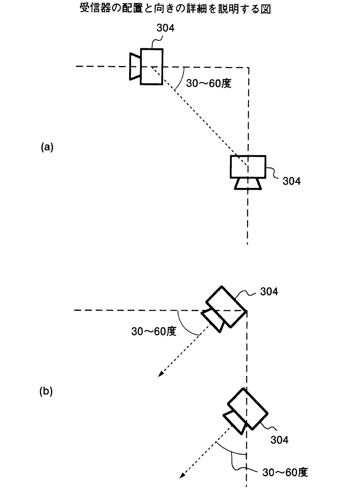
つまり、図7(a)に詳示するように図5における受信器304の場合には2個の受信器304を並べる方法を、2個の受信器304を結ぶ直線と用紙の上辺とのなす角度が30度〜60度となるように制限するものである。この場合、受信器304の向き自体は特に考慮していない。
【0030】
そして、さらに戻って、図6に示すように2個の受信器304の向きが、この受信器304の最大感度方向(矢印の向き)である用紙の上端部に対して30〜60度の向き(方向)となるように、受信器304を固定することが指向性の観点から適当であるといえる。
【0031】
すなわち、図7(b)に詳示するように図6における受信器304の場合には2個の受信器304の向き(方向)を最大感度方向である用紙の上端部に対して30〜60度の向きとして制限するものである。この場合、2個の受信器304の並べ方自体は特に考慮していない。
【0032】
そして、図8に示すように、より好ましくは2個の受信器304を結ぶ直線と用紙の上辺とのなす角度が45度で、かつ受信器304の最大感度方向を2個の受信器304を結ぶ直線と90度、すなわち用紙の上辺とのなす角度を45度になるように固定する。このようにするためには、戻って図3に示すように受信機101を構成する下半部303の表面にほぼ90度の角度(傾斜部)に設定されたエッジ部307を形成する。これにより、用紙の角部を受信機101により固定する際には、用紙をエッジ部307に沿って挿入することにより自動的に用紙に対する受信機101の配置角度を最大の指向性となる45度の傾斜位置に配置させることができる。
【0033】
なお、この例ではエッジ部307の形成位置を下半部303側としているが、このエッジ部307を上半部302側に形成しても、同様に受信機101の配置角度を最大の指向性となる45度の傾斜位置に配置させることができるという作用効果を得ることができる。
【0034】
ここで、前述したように本発明の特徴は受信機101に備えている2個の超音波受信器304の死角を無くし見かけ上の間隔を狭くしないために、この受信機101の配置位置が用紙の角部となるように構成としたことにある。そして、このように受信機101を用紙の角部に配置するためには2個の受信器間隔Wを小さくし、受信機101自体の大きさをコンパクトにし小型化とする必要がある。これは、前述したよう受信器間隔Wが大きいと良好な分解能を得ることはできるがその反面、死角が生じたり、装置が大型化するという不具合を招くためである。
【0035】
つまり、超音波による距離測定のばらつきは、超音波が伝播する空気中の温度揺らぎと受信器のセンサアンプノイズとに起因しているが、これらは何れも受信器304とぺんポイント(ぺん102による筆記位置)との間隔である距離Lに比例して大きくなる。さらに、三角測量での座標ばらつきeは距離Lに比例し、2個の受信器304同士の受信器間隔Wに反比例することが判明している。このため、本発明者は必要な分解能を維持できる上、可能な限り小さい選定値の受信器間隔Wを得るべく、図9に示すような実験を行った(距離と誤差との関係図)。
【0036】
以下、図9の実験結果と前記図6の受信機の配置を説明する原理図を参照して説明する。この実験では受信器間隔Wを25mmに選定し、距離と座標ばらつきとの関係を実験により求めるもので、具体的には超音波受信器304からぺん102を徐々に離隔させた時に測定距離のばらつきがどの程度生じるかの実験を行った。ここで、図中の横軸は実際の距離値(mm)を、縦軸は誤差(mm)、黒点は超音波受信器で得た距離の測定値を、グラフは算出式により算出された計算値による推移をそれぞれ示している。この測定結果から、三角測量での座標ばらつきeは、
e=0.0002L2/W
の算定式から凡その値として求めることができる。
【0037】
そして、上述した算定式から逆算して使用する用紙の大きさ(用紙の対角線の長さ)と必要な分解能が決まれば、必要とする最小となる受信器間隔Wを得ることができる。つまり、受信機101を用紙の角部に固定する場合、対角線の長さが最も離隔した距離となり、この距離が受信器304とぺんポイントが最も離れている距離となる。また、実際の通常の筆記の場合には±0.1〜1mmの分解能が必要であることから、対角線の長さP(ぺんのぺんポイント位置である距離LをPに置き換える)とすると、受信器間隔Wは、
W=0.0002P2〜0.002P2
の算定式から求めることができる。
【0038】
そして、この算定式に基いて、本実施の形態1の発明では用紙における対角線の長さをPとした場合に、2個の受信器同304同士の配置間隔Wの設定値を0.0002P2よりも大きく、且つ0.002P2よりも小さくなるようにするものとしている。そして、このように設定した受信器間隔Wに基いて受信器304を配置させて受信機101を構成した場合には、受信機101を小型化にすることが可能となり、最大の指向性を得ることができる用紙の角部に、この受信機101を配置することが可能となる。
【0039】
上述してきたように、本実施の形態1における受信機101は、一対の超音波受信器304と赤外線受信器305とを有する上半部302と、この上半部の基端部に枢支される下半部303とからなる用紙の角部を挟持し固定自在な固定部材として構成されると共に、受信機101による用紙に対する固定位置は一対の超音波受信器304同士を結ぶ直線と用紙の上辺とのなす角度が30度から60度の範囲となる位置に設定される構成としたので、受信器304の死角が無く、この受信器304の見かけ上の間隔を狭くしないうえ、これにより装置の構成を小型化とすることが可能となり、操作性及び可搬性がよく携帯用として利用することができる。
【0040】
次に、図10を参照して本発明に適用される専用ぺんの構成を説明する。すなわち、図10に示すように、ぺん102の先端部には筆記用のボールペン芯702が取り付けられており、ぺん102の内部にはボールペン芯702と用紙の筆記面との接触を検知するための接触検知スイッチ703が設けられている。また、このぺん102の先端側には円筒状の超音波送信器704と赤外線送信器705とが設けられており、このうち超音波送信器704はポリフッ化ビニリデン製の圧電フィルム(PVDF)から構成されている。この圧電フィルムは電圧が印加された際に振動して超音波を発生する機能がある。
【0041】
ここで、超音波送信器704の形状は超音波の指向性を360度とすることができる円筒状となっている。このため、筆記時にぺん102が回転しても発信した超音波パルスを正確に受信器304まで到達させることができる。また、赤外線送信器705も指向性が120度のものが3個均等に配置されており、やはり筆記時にぺん102が回転しても発信した赤外線パルスを正確に受信器304まで到達させることができる。
【0042】
また、708は駆動回路部で、この駆動回路部708は単4の電池709により駆動される。具体的には手書きによる筆記をおこなう際、ぺん102の先端が用紙の筆記面に接触した時だけ、接触検知スイッチ703がONとなり、超音波及び赤外線の送信が行われるものとなる。このように、ぺん102による筆記時以外の時には超音波及び赤外線の送信を防止することにより省電力化を図っている。
【0043】
図11は上述した専用のぺん102に適用される駆動回路部708の回路構成を示すブロック図である。すなわち、図11に示すように駆動回路部708はタイマ710と赤外線駆動回路711と超音波駆動回路712とからなり、ぺん102の芯702と用紙の筆記面とが接触し、この接触が接触検知スイッチ703により検知されると、タイマ710による赤外線駆動回路711と超音波駆動回路712との作動により一定周期(50Hz〜100Hz)赤外線送信器705から赤外線パルスが、超音波送信器704から超音波パルスが発生する。なお、ここでの周期は人間の手によるぺん102の動きが安定して検出できればよいため50Hz程度の一定周期となるように設定されている。
【0044】
(実施の形態2)
次に、図12を参照して本実施の形態2に係る座標入力装置801の構成について説明する。このうち、図12(a)は平面図を、図12(b)は側面図をそれぞれ示している。ここで、この実施の形態2において、前述した本実施の形態1と相違する点は受信機803を構成する上半部302の下方に平板状のボード802(下半部303に相当する)を設け、このボード802の上部に用紙を載置するようにしたことに特徴がある。
【0045】
すなわち、これら上半部302及びボード802の基端部側(図で右側)は枢軸306により枢支されており、上半部302はボード802に対して枢軸306を基点として開閉自在(図12(b))となっているため、ボード802に用紙の角部を挟持するとともに、固定できるようになっている。
【0046】
また、このボード802の板厚は薄肉の厚さに選定されているとともに、用紙の大きさ(例えば、A4サイズ)とほぼ同寸法に選定された寸法となっている。
【0047】
また、ボード802に対する受信機803の固着位置は、ボード802の角部であるとともに、ボード802の上辺との角度が30度から60度の範囲となるように選定されるもので、具体的には用紙に対する指向性が最大となる45度の向きになっている。
【0048】
さらに、前述したように本実施の形態2で採用するボード802は薄肉の板厚に選定されているため、用紙に対する下敷きとして機能するうえ、タブレットのように持ち運びに適さないものではなく、これにより携帯に便利な座標入力装置として利用することができる。そして、このボード802の大きさは使用頻度が多いA4サイズなどに限定されるものではなく、B5サイズなどの小さいサイズに寸法を選定した場合には、より携帯に適した座標入力装置801として使用することができる。
【0049】
上述してきたように、本実施の形態2における座標入力装置801は、受信機803を構成する上半部302の下方に下半部303に相当する平板状のボード802を設け、このボード802の上部に用紙を載置するようにし、この用紙の角部をボード801の上辺との角度が30度から60度の範囲となるように選定し、固定する構成としたので、受信器304の死角が発生せず、しかも受信器304の見かけ上の間隔が狭くならず、ボード802が下敷きとして機能するためぺん102による筆記時の操作性及び可搬性がよく携帯用として利用することができる。
【0050】
また、図13は受信機803と挟持手段であるクリップ809を別体として、このクリップ809をボード802の上部に設け、このクリップ809により用紙を挟むようにした座標入力装置805を示すものである。そして、この場合もボード802に対する上半部302の固定位置は、ボード802の角部であるとともに、このボード802の上辺との角度が30度から60度の範囲となるように選定されるもので、具体的には用紙に対する受信器304の指向性が最大となる45度の向きになっている。
【0051】
この場合、クリップ809によって用紙を固定することができるため、前述したように上半部302には枢軸306を設けるなどの、用紙を挟む機構を備える必要がなくなる。
【0052】
図14は本実施の形態1、2に適用することのできる受信機の電気回路である内部ブロック図の一例を、図15は超音波受信器により受信された超音波パルスの波形(タイミングチャート)をそれぞれ示している。
【0053】
すなわち、図14に示すように内部回路は超音波受信器に受信した超音波パルスを増幅する入力アンプ111a,111b、比較用のコンパレータ112a,112b、零クロスコンパレータ113a,113b、FF114a,114b(フリップフロップ)、タイマ115a,115b、マイクロコントローラ116とにより構成されている。そして、このように構成される電気構成により超音波伝播時間T1,T2を検出することができる。
【0054】
まず、最初に赤外線送信器705(図10)から発信された赤外線パルスを赤外線受信器305(図3)が受信することによりタイマ115a(115b)がスタート(Start信号)する。次いで、2個の超音波受信器304により受信された超音波パルスは、それぞれ入力アンプ111aにより適度な大きさに増幅される(図15参照)。以下、入力アンプ111aにより増幅後の超音波パルスのうちコンパレータ112aでシュレッシュホールドとしての閾値rt1を取り出し、この閾値rt1よりも超音波パルスが大きい場合にはFF114a(フリップフロップ)がONされる。さらに、零クロスコンパレータ113aで零クロス(Z点)を検出し、これら両者の論理積(アンド)によりタイマ115aをストップ(Stop信号)させる。この時、閾値rt1を超えた次の零クロス位置を検出する。この零クロス位置が検出された時刻が受信器に対する超音波パルスの到着時刻となる。
【0055】
そこで、赤外線発信器705からの赤外線同期信号に基いて超音波パルスの到着までの超音波伝播時間T1をタイマで検出する。以下、他方の超音波受信器304に関しても同様のシーケンスにより伝播時間T2を検出し、このようにして検出した伝播時間T1,T2をマイクロコンピュータ116に入力する。後述するように、このように検出された伝播時間T1,T2に基いて筆記位置であるペンポイントから受信器304までの距離を算出することができる。
【0056】
図16はマイクロコンピュータとパソコン内部での処理を示したフローチャートである。このフローチャートを参照して、検出した超音波伝播時間T1,T2からパソコン上での座標を算出する方法を説明する。すなわち、図12に示すように先ずマイクロコントローラ116の処理としては、タイマ115a,115bから伝播時間T1,T2をそれぞれ読み出す処理を行う(ステップ:S120)。これら読み出した伝播時間T1,T2をパソコンに対してUSBポートを経由して転送する(ステップ:S121)。
【0057】
以下は、パソコン内部での処理であるが、このパソコン内部では伝播時間T1,T2をマイクロコントローラ116から読み出す処理が行われ(ステップ:S122)、次いで、これら伝播時間T1,T2からペンポイントと2個の受信器304までの距離である距離L1,距離L2を算出する距離計算を行う(ステップ:S123)。すなわち、音速をV,受信器との受信器間距離をWとすると、距離L1,距離L2は、
L1=V×T1
L2=V×T2
の算出式により算出することができる。
【0058】
次いで、前記(ステップ:S123)の算出式により算出された距離L1,距離L2に基いてパソコン上での座標位置を算出する座標計算処理が行われる(ステップ:S124)。つまり、2個の受信機304のうち一方の受信器304の位置を原点とし、もう一方の受信器304の位置を(W,0)となる座標系として取ると、所定のぺんの座標(x,y)は、
x2+y2=L12
(x−W)2+y2=L22
であるから、これらの算定式によりx,yについて解法すると、その座標は、
【数1】
【0059】
さらに、パソコン上ではパソコン画面でのマウス座標計算が必要となるため、マウスカーソル位置を特定する座標計算を行う(ステップ:S125)。すなわち、マウス座標を(X,Y)とすると、この座標は、
X=a11x+a12y+b1
Y=a21x+a22y+b2
の算定式から求めることができる。ここで、座標変換の係数a11、a12、a21、a22、b1、b2は前もって内部構成としてのキャリブレーションにより決めておくものとする。
【0060】
次いで、上述した(ステップ:S125)により求められたマウス座標(X,Y)に基いて、マウスカーソルを移動する処理を行う(ステップ:S126)。以降、(ステップ:S120)〜(ステップ:S126)の処理を繰り返して行うことにより所望の座標入力を行うことができる。なお、実際にパソコン画面上にぺんによる軌跡を表すものとしては例えば、ペイントブラシなどの汎用アプリケーションソフトを使用することができる。また、具体的に手書きにより用紙に筆記された文字などはパソコン内部にビットマップデータにより保存されるものとなる。
【0061】
(付記1)超音波を発信するぺんと、該ぺんから発信された超音波を複数の超音波受信器で受信する受信機とを有し、前記受信機の各超音波受信器でそれぞれ受信した超音波の伝播時間に基づいて前記ぺんの座標位置を入力する座標入力装置であって、
前記受信機は、
前記ぺんから発信された超音波を受信する複数の超音波受信器と、
所定の用紙の角部を挟持する挟持手段と、
を有することを特徴とする座標入力装置。
【0062】
(付記2)前記挟持手段は、前記ぺんにより筆記を行なう用紙を載置する平板状のボードに固着されたことを特徴とする付記1に記載の座標入力装置。
【0063】
(付記3)前記ぺんは、赤外線パルスを発信する赤外線発信器を有し、前記受信機は、前記赤外線発信器から発信された赤外線パルスを同期信号として受信する赤外線受信器をさらに備えたことを特徴とする付記1または付記2に記載の座標入力装置。
【0064】
(付記4)前記受信機は前記複数の超音波受信器同士を結ぶ直線と前記用紙の上辺とのなす角度が30度から60度の範囲となる位置に前記用紙を固定することを特徴とする付記1,2または付記3に記載の座標入力装置。
【0065】
(付記5)前記第1,2の挟持手段のいずれかの用紙に対する挟持面には当該用紙の角部を突き当て自在なほぼ90度の向きに設定されたエッジ部が形成されていることを特徴とする付記1〜4のいずれか一つに記載の座標入力装置。
【0066】
(付記6)前記一対の超音波受信器同士の配置間隔をWとし、筆記手段による筆記範囲である用紙における対角線の長さをPとした場合に、受信器の配置間隔Wは0.0002P2よりも大きく0.002P2よりも小さくなるように設定されることを特徴とする付記1〜5のいずれか一つに記載の座標入力装置。
【0067】
(付記7)前記超音波受信器の最大感度方向が用紙における筆記範囲の上辺とのなす角度が30度から60度の範囲になるように設定されていることを特徴とする付記1〜5のいずれか一つに記載の座標入力装置。
【0068】
【発明の効果】
以上説明したように、請求項1の発明によれば、受信機は、ぺんから発信された超音波を受信する複数の超音波受信器と、所定の用紙の角部を挟持する挟持手段とを有するので、受信器の死角が発生せず、この受信器の見かけ上の間隔が狭くなることを防止でき、用紙の角部に配置させて、固定することができるため、座標入力装置の構成を小型化とすることが可能となり、操作性及び可搬性がよく携帯用として利用することができるという効果を奏する。
【0069】
また、請求項2の発明によれば、挟持手段は、ぺんにより筆記を行なう用紙を載置する平板状のボードに固着されているので、予め受信機は挟持手段によりボードの角部に配置固定されていることから、受信器の死角が発生せず、この受信器の見かけ上の間隔が狭くなることを防止できるうえ、用紙を載置するボードが下敷きとして機能することから筆記時の操作性及び可搬性がよく携帯用の装置として利用することができるという効果を奏する。
【0070】
また、請求項3の発明によれば、ぺんは赤外線パルスを発信する赤外線発信器を有し、受信機は、前記赤外線発信器から発信された赤外線パルスを同期信号として受信する赤外線受信器をさらに備えたので、ぺんを有線により接続することなく受信機に赤外線パルスの同期信号を発信することができるという効果を奏する。
【0071】
また、請求項4の発明によれば、受信機は前記複数の超音波受信器同士を結ぶ直線と前記用紙の上辺とのなす角度が30度から60度の範囲となる位置に前記用紙を固定するので、受信器の死角が発生せず、この受信器の見かけ上の間隔が狭くなることを防止できるうえ、操作性及び可搬性がよく携帯用の装置として利用することができるという効果を奏する。
【0072】
また、請求項5の発明によれば、挟持手段のいずれかの用紙に対する挟持面には当該用紙の角部を突き当て自在なほぼ90度の向きに設定されたエッジ部が形成されているので、用紙をエッジ部に沿って挿入することにより自動的に用紙に対する受信機の配置角度を最大の指向性となる45度の傾斜位置に配置させることができ、さらに低価格化を図ることができるという効果を奏する。
【図面の簡単な説明】
【図1】実施の形態1にかかる座標入力装置の適用例である全体構成を説明するための図である。
【図2】受信機の配置を説明するための図である。
【図3】受信機の構成(上視図、正面図、側面図)を説明するための図である。
【図4】受信機による用紙の挟持手順を説明するための図である。
【図5】受信器の配置を説明するための図である。
【図6】受信器の向きを説明するための図である。
【図7】受信器の配置と向きの詳細を説明するための図である。
【図8】受信器の最大感度方向を説明するための図である。
【図9】距離と誤差の関係図である実験結果を説明するための図である。
【図10】専用ぺんの内部構成を説明するための図である。
【図11】駆動回路部の内部ブロックを説明するための図である。
【図12】実施の形態2に係る座標入力装置の適用例である全体構成を説明するための図である。
【図13】受信機とクリップを別体とした座標入力装置の全体構成を説明するための図である。
【図14】受信機の電気回路部である内部ブロック図の一例を説明するための図である。
【図15】超音波受信器により受信された超音波パルスの波形(タイミングチャート)を説明する図である。
【図16】マイクロコントローラおよびパソコンソフトの処理フローチャートである。
【図17】従来の座標処理装置の構成を説明する図である。
【符号の説明】
100,801,805 座標入力装置
101,803 受信機
102 ぺん
104 コンピュータ
111a,b 入力アンプ
112a,112b コンパレータ
113a,113b 零クロスコンパレータ
114a,114b FF
115a,115b,710 タイマ
116 マイクロコントローラ
304 超音波受信器
305 赤外線受信器
307 エッジ部
704 超音波送信器
705 赤外線送信器
711 赤外線駆動回路
712 超音波駆動回路
802 ボード[0001]
BACKGROUND OF THE INVENTION
The present invention relates to a coordinate input device for inputting, as character data or graphic data, a trajectory when a character or graphic is handwritten on a paper with a dedicated pen, and in particular, there are few areas that are blind spots, and The present invention relates to a coordinate input device using ultrasonic waves with good operability and portability.
[0002]
[Prior art]
With the recent spread of personal computers, it is becoming more common to input electronic documents using the keyboard rather than handwriting characters on paper using a pencil, etc. It is easier to actually hand-write characters on a sheet than to input with a keyboard.
[0003]
For this reason, it is still common to bring your own memo pad, etc. to a meeting, etc., and use a pencil to write by hand into the memo pad, but distribute and manage your memos to others. Considering this, it is desirable that such memos be digitized. In particular, if handwritten characters are read by an image scanner or the like, the processing required for digitization is complicated, and using a touch panel or tablet is inconvenient to carry. Therefore, it is desirable to easily input handwritten characters as electronic data. It is rare.
[0004]
For these reasons, conventionally, a pair of ultrasonic receivers are arranged on a sheet, ultrasonic waves transmitted from the pen are received by these ultrasonic receivers, and coordinates are obtained by triangulation from the propagation time of the ultrasonic waves. A coordinate input device for inputting is known. For example, in JP-A-8-36462 and JP-A-2000-298547, two receivers constituting a receiver are arranged on a desk or a base, and ultrasonic waves propagate to these receivers. A technique is disclosed in which the distance between the pen and the receiver is continuously measured from the propagation time to obtain the pen coordinates on the desk by using the triangulation method. In order to synchronize the time when ultrasonic waves are generated from the pen, an infrared receiver is provided on the desk, and infrared rays from the pen are received by the infrared receiver.
[0005]
[Problems to be solved by the invention]
However, when the conventional technology using such triangulation is used, an area that becomes a blind spot occurs in a part of the paper, and it becomes impossible to input coordinates, or even if input is possible, the resolution deteriorates as a result. There is a problem. Further, when trying to avoid such a blind spot, there arises a problem that the apparatus is increased in size and cost.
[0006]
FIG. 17 is a diagram illustrating an example of a configuration of a conventional coordinate input device. As shown in FIG. 5A, in triangulation, the larger the distance between two receivers constituting the receiver, the better the coordinate resolution, which is the degree of discrimination. Therefore, two
[0007]
However, since the directivity of the ultrasonic receiver and the infrared receiver is generally about ± 45 to 60 degrees, there is a problem that an area that becomes a blind spot is generated on the left and right sides of the upper end of the sheet. In other words, for example, when the pen position (writing position) is at point A in the figure, it becomes impossible to input coordinates due to restrictions on the directivity of ultrasonic waves and infrared rays, and even if it can be input, the resolution is significantly degraded. Problem arises.
[0008]
In order to eliminate the blind spot due to the directivity of the ultrasonic waves and infrared rays, it is necessary to fix the
[0009]
For this reason, as shown in FIG. 17C, it is conceivable to arrange the
[0010]
For these reasons, it is an extremely important issue how to realize a coordinate input device using ultrasonic waves with few blind spots and good operability and portability.
[0011]
The present invention has been made to solve the above-described problems caused by the prior art, and provides an ultrasound-based coordinate input device that has a small number of blind spots and that has good operability and portability. With the goal.
[0012]
[Means for Solving the Problems]
In order to solve the above-described problems and achieve the object, a coordinate input device according to
[0013]
According to the invention of
[0014]
According to a second aspect of the present invention, there is provided the coordinate input device according to the first aspect of the invention, wherein the clamping means is a flat board (on the
[0015]
According to the second aspect of the present invention, since the receiver is arranged and fixed in advance at the corner of the board by the clamping means, it is possible to cover the entire area of the sheet with a directivity of ± 45. Since the blind spot does not occur and the board on which the paper is placed functions as an underlay, the operability and portability at the time of writing are good and can be used as a portable device.
[0016]
According to a third aspect of the present invention, there is provided the coordinate input device according to the first or second aspect, wherein the pen includes an infrared transmitter that transmits an infrared pulse, and the receiver is transmitted from the infrared transmitter. And an infrared receiver (corresponding to the
[0017]
According to the third aspect of the invention, an infrared pulse synchronization signal can be transmitted to the receiver without connecting the pen by wire.
[0022]
DETAILED DESCRIPTION OF THE INVENTION
Exemplary embodiments of a coordinate input device according to the present invention will be explained below in detail with reference to the accompanying drawings.
[0023]
(Embodiment 1)
First, the configuration of the coordinate input device according to the first embodiment will be described. 1 is a system configuration diagram with a personal computer which is an application example of a coordinate input device, FIG. 2 is an explanatory diagram showing an example of the arrangement of a receiver, and FIG. 3 is a configuration diagram of the receiver (top view, front view, side view). Respectively).
[0024]
That is, as shown in FIG. 1, the coordinate
[0025]
Here, FIGS. 2A and 2B are explanatory views showing examples of arrangement of the
[0026]
FIG. 3 is a block diagram of the receiver, showing (a) a top view, (b) a front view, and (c) a side view. FIGS. 4A and 4B are diagrams for explaining a fixing procedure for a sheet by the receiver. Hereinafter, the configuration of the receiver will be described with reference to FIGS. That is, as shown in FIG. 3, the
[0027]
Further, since the base end side (right side in the figure) of the
[0028]
Here, as described in the conventional problem, when the
[0029]
That is, as shown in detail in FIG. 7A, in the case of the
[0030]
Then, returning further, as shown in FIG. 6, the orientation of the two
[0031]
That is, as shown in detail in FIG. 7B, in the case of the
[0032]
As shown in FIG. 8, more preferably, the angle between the straight line connecting the two
[0033]
In this example, the
[0034]
Here, as described above, the feature of the present invention is that the arrangement position of the
[0035]
In other words, the variation in distance measurement by ultrasonic waves is caused by temperature fluctuations in the air through which the ultrasonic waves propagate and sensor amplifier noise of the receiver, both of which depend on the
[0036]
Hereinafter, description will be made with reference to the experimental results of FIG. 9 and the principle diagram illustrating the arrangement of the receivers of FIG. In this experiment, the receiver interval W is selected to be 25 mm, and the relationship between the distance and the coordinate variation is obtained by experiment. Specifically, when the
e = 0.0002L2/ W
It can be calculated as an approximate value from the above formula.
[0037]
Then, if the size of the paper to be used (the length of the diagonal line of the paper) and the necessary resolution are determined by calculating backward from the above-described calculation formula, the minimum required receiver interval W can be obtained. That is, when the
W = 0.0002P2~ 0.002P2
It can be calculated from the following formula.
[0038]
Based on this calculation formula, in the invention of the first embodiment, when the length of the diagonal line on the sheet is P, the setting value of the arrangement interval W between the two
[0039]
As described above, the
[0040]
Next, the configuration of the dedicated pen applied to the present invention will be described with reference to FIG. That is, as shown in FIG. 10, a
[0041]
Here, the shape of the
[0042]
[0043]
FIG. 11 is a block diagram showing a circuit configuration of the
[0044]
(Embodiment 2)
Next, the configuration of the coordinate
[0045]
That is, the
[0046]
The thickness of the
[0047]
In addition, the position where the
[0048]
Furthermore, as described above, since the
[0049]
As described above, the coordinate
[0050]
FIG. 13 shows a coordinate
[0051]
In this case, since the paper can be fixed by the
[0052]
FIG. 14 is an example of an internal block diagram that is an electric circuit of a receiver that can be applied to the first and second embodiments. FIG. 15 is a waveform (timing chart) of an ultrasonic pulse received by the ultrasonic receiver. Respectively.
[0053]
That is, as shown in FIG. 14, the internal circuit has
[0054]
First, when the infrared receiver 305 (FIG. 3) receives the infrared pulse transmitted from the infrared transmitter 705 (FIG. 10), the
[0055]
Therefore, the ultrasonic propagation time T1 until the arrival of the ultrasonic pulse is detected by a timer based on the infrared synchronization signal from the
[0056]
FIG. 16 is a flowchart showing processing in the microcomputer and the personal computer. A method for calculating coordinates on the personal computer from the detected ultrasonic propagation times T1 and T2 will be described with reference to this flowchart. That is, as shown in FIG. 12, first, as a process of the
[0057]
The following is processing in the personal computer. In this personal computer, processing for reading out the propagation times T1 and T2 from the
L1 = V × T1
L2 = V × T2
It can be calculated by the following formula.
[0058]
Next, coordinate calculation processing for calculating a coordinate position on the personal computer based on the distance L1 and the distance L2 calculated by the calculation formula of (Step: S123) is performed (Step: S124). In other words, if the position of one of the two
x2+ Y2= L12
(X-W)2+ Y2= L22
Therefore, when solving for x and y by these formulas, the coordinates are
[Expression 1]
[0059]
Furthermore, since it is necessary to calculate mouse coordinates on the personal computer screen on the personal computer, coordinate calculation for specifying the mouse cursor position is performed (step: S125). That is, if the mouse coordinate is (X, Y), this coordinate is
X = a11x + a12y + b1
Y = a21x + a22y + b2
It can be calculated from the following formula. Here, it is assumed that the coefficients a11, a12, a21, a22, b1, and b2 for coordinate conversion are determined in advance by calibration as an internal configuration.
[0060]
Next, a process of moving the mouse cursor is performed based on the mouse coordinates (X, Y) obtained in the above (Step: S125) (Step: S126). Thereafter, the desired coordinate input can be performed by repeating the processes of (Step: S120) to (Step: S126). For example, general-purpose application software such as a paint brush can be used to actually represent a pen trajectory on a personal computer screen. In addition, specifically, characters written on paper by handwriting are stored in the personal computer as bitmap data.
[0061]
(Additional remark 1) It has the pen which transmits an ultrasonic wave, and the receiver which receives the ultrasonic wave transmitted from this pen with a some ultrasonic receiver, Each received by each ultrasonic receiver of the said receiver A coordinate input device for inputting the coordinate position of the pen based on the propagation time of ultrasonic waves,
The receiver
A plurality of ultrasonic receivers for receiving ultrasonic waves transmitted from the pen;
Clamping means for clamping a corner of a predetermined sheet;
A coordinate input device comprising:
[0062]
(Supplementary note 2) The coordinate input device according to
[0063]
(Supplementary Note 3) The pen includes an infrared transmitter that transmits an infrared pulse, and the receiver further includes an infrared receiver that receives the infrared pulse transmitted from the infrared transmitter as a synchronization signal. The coordinate input device according to
[0064]
(Supplementary Note 4) The receiver fixes the sheet at a position where an angle formed between a straight line connecting the plurality of ultrasonic receivers and an upper side of the sheet is in a range of 30 degrees to 60 degrees. The coordinate input device according to
[0065]
(Supplementary Note 5) An edge portion set at an angle of about 90 degrees is formed on the clamping surface of any one of the first and second clamping means with respect to the paper so that the corner of the paper can be abutted. 5. The coordinate input device according to any one of
[0066]
(Supplementary note 6) When the arrangement interval between the pair of ultrasonic receivers is W and the length of the diagonal line in the paper which is the writing range by the writing means is P, the arrangement interval W of the receiver is 0.0002P.2Larger than 0.002P2The coordinate input device according to any one of
[0067]
(Additional remark 7) The maximum sensitivity direction of the said ultrasonic receiver is set so that the angle made with the upper side of the writing range in a paper may be set to the range of 30 to 60 degree | times, The additional notes 1-5 characterized by the above-mentioned The coordinate input device according to any one of the above.
[0068]
【The invention's effect】
As described above, according to the first aspect of the present invention, the receiver includes a plurality of ultrasonic receivers that receive the ultrasonic waves transmitted from the pen, and the clamping means that clamps the corners of a predetermined sheet. As a result, the blind spot of the receiver does not occur, the apparent interval between the receivers can be prevented from being narrowed, and the receiver can be arranged and fixed at the corners of the paper. It is possible to reduce the size, and the operability and portability are good, and there is an effect that it can be used for portable use.
[0069]
According to the second aspect of the present invention, since the holding means is fixed to the flat board on which the paper to be written is placed with a pen, the receiver is arranged and fixed in advance at the corner of the board by the holding means. Therefore, the blind spot of the receiver does not occur, the apparent interval between the receivers can be prevented from being narrowed, and the board on which the paper is placed functions as an underlay, so operability during writing In addition, there is an effect that it is portable and can be used as a portable device.
[0070]
According to a third aspect of the present invention, the pen has an infrared transmitter that transmits an infrared pulse, and the receiver further includes an infrared receiver that receives the infrared pulse transmitted from the infrared transmitter as a synchronization signal. Since it is provided, it is possible to transmit an infrared pulse synchronization signal to the receiver without connecting the pen by wire.
[0071]
According to a fourth aspect of the present invention, the receiver fixes the sheet at a position where an angle between a straight line connecting the plurality of ultrasonic receivers and the upper side of the sheet is in a range of 30 degrees to 60 degrees. As a result, the blind spot of the receiver does not occur, the apparent interval between the receivers can be prevented from becoming narrow, and the operability and portability can be improved and the apparatus can be used as a portable device. .
[0072]
According to the invention of claim 5, since the clamping surface of any one of the clamping means with respect to the sheet is formed with an edge part set at an angle of approximately 90 degrees so that the corner of the sheet can be abutted. By inserting the paper along the edge portion, the receiver can be automatically placed at an inclined position of 45 degrees with the maximum directivity with respect to the paper, and the cost can be further reduced. There is an effect.
[Brief description of the drawings]
FIG. 1 is a diagram for explaining an overall configuration as an application example of a coordinate input apparatus according to a first embodiment;
FIG. 2 is a diagram for explaining the arrangement of receivers;
FIG. 3 is a diagram for explaining a configuration (upper view, front view, side view) of a receiver.
FIG. 4 is a diagram for explaining a paper nipping procedure by a receiver;
FIG. 5 is a diagram for explaining the arrangement of receivers;
FIG. 6 is a diagram for explaining the orientation of a receiver.
FIG. 7 is a diagram for explaining details of the arrangement and orientation of a receiver.
FIG. 8 is a diagram for explaining a maximum sensitivity direction of a receiver.
FIG. 9 is a diagram for explaining an experimental result which is a relationship diagram between a distance and an error.
FIG. 10 is a diagram for explaining an internal configuration of a dedicated pen.
FIG. 11 is a diagram for explaining an internal block of a drive circuit unit;
12 is a diagram for explaining an overall configuration as an application example of a coordinate input apparatus according to Embodiment 2. FIG.
FIG. 13 is a diagram for explaining an overall configuration of a coordinate input device in which a receiver and a clip are separated.
FIG. 14 is a diagram for explaining an example of an internal block diagram that is an electric circuit unit of a receiver;
FIG. 15 is a diagram illustrating a waveform (timing chart) of an ultrasonic pulse received by an ultrasonic receiver.
FIG. 16 is a processing flowchart of a microcontroller and personal computer software;
FIG. 17 is a diagram illustrating a configuration of a conventional coordinate processing apparatus.
[Explanation of symbols]
100, 801, 805 Coordinate input device
101,803 receiver
102
104 computer
111a, b Input amplifier
112a, 112b Comparator
113a, 113b Zero cross comparator
114a, 114b FF
115a, 115b, 710 timer
116 Microcontroller
304 Ultrasonic receiver
305 Infrared receiver
307 Edge
704 Ultrasonic transmitter
705 Infrared transmitter
711 Infrared drive circuit
712 Ultrasonic drive circuit
802 board
Claims (3)
前記受信機は、
前記ぺんから発信された超音波を受信する複数の超音波受信器と、
所定の用紙の角部を挟持する挟持手段と、
前記挟持手段によって挟持される前記用紙の角部が当接されるほぼ90度からなるエッジ部と、
を有し、
前記複数の超音波受信器は、前記エッジ部に前記用紙の角部が当接された際の当該用紙の上辺と前記複数の超音波受信器同士を結ぶ直線とのなす角度が30度から60度の範囲となるように配置されることを特徴とする座標入力装置。Propagation of ultrasonic waves received by each ultrasonic receiver of the receiver, having a pen for transmitting ultrasonic waves and a receiver for receiving ultrasonic waves transmitted from the pens by a plurality of ultrasonic receivers A coordinate input device for inputting the coordinate position of the pen based on time,
The receiver
A plurality of ultrasonic receivers for receiving ultrasonic waves transmitted from the pen;
Clamping means for clamping a corner of a predetermined sheet;
An edge portion of approximately 90 degrees with which a corner portion of the paper held by the holding means comes into contact;
Have
In the plurality of ultrasonic receivers, an angle formed between an upper side of the sheet and a straight line connecting the plurality of ultrasonic receivers when a corner portion of the sheet comes into contact with the edge portion is 30 degrees to 60 degrees. The coordinate input device is arranged so as to be in a range of degrees .
Priority Applications (5)
| Application Number | Priority Date | Filing Date | Title |
|---|---|---|---|
| JP2002054982A JP4068366B2 (en) | 2002-02-28 | 2002-02-28 | Coordinate input device |
| KR1020020079608A KR100893114B1 (en) | 2002-01-31 | 2002-12-13 | Ultrasonic distance measuring device and method for coordinate input |
| CNB031017568A CN100347519C (en) | 2002-01-31 | 2003-01-21 | Ultrasonic length measuring device and method for coordinate input |
| EP03250585A EP1347365A3 (en) | 2002-01-31 | 2003-01-30 | Ultrasonic length measuring apparatus and method for coordinate input |
| US10/354,196 US6944557B2 (en) | 2002-01-31 | 2003-01-30 | Ultrasonic length measuring apparatus and method for coordinate input |
Applications Claiming Priority (1)
| Application Number | Priority Date | Filing Date | Title |
|---|---|---|---|
| JP2002054982A JP4068366B2 (en) | 2002-02-28 | 2002-02-28 | Coordinate input device |
Publications (2)
| Publication Number | Publication Date |
|---|---|
| JP2003256126A JP2003256126A (en) | 2003-09-10 |
| JP4068366B2 true JP4068366B2 (en) | 2008-03-26 |
Family
ID=28665937
Family Applications (1)
| Application Number | Title | Priority Date | Filing Date |
|---|---|---|---|
| JP2002054982A Expired - Fee Related JP4068366B2 (en) | 2002-01-31 | 2002-02-28 | Coordinate input device |
Country Status (1)
| Country | Link |
|---|---|
| JP (1) | JP4068366B2 (en) |
Families Citing this family (3)
| Publication number | Priority date | Publication date | Assignee | Title |
|---|---|---|---|---|
| US8431841B2 (en) * | 2009-01-29 | 2013-04-30 | Pegasus Technologies Ltd. | Rangefinder pivotable between obverse and reverse positions |
| JP5262761B2 (en) * | 2009-01-29 | 2013-08-14 | ぺんてる株式会社 | Handwriting input system |
| KR200471137Y1 (en) | 2012-09-10 | 2014-02-10 | 주식회사 피엔에프 | Information input apparatus |
Family Cites Families (5)
| Publication number | Priority date | Publication date | Assignee | Title |
|---|---|---|---|---|
| JPH01172140U (en) * | 1988-05-20 | 1989-12-06 | ||
| CA2074077A1 (en) * | 1990-01-19 | 1991-07-20 | Robert Butler | Position determining apparatus and method |
| EP0655674B1 (en) * | 1993-11-30 | 2000-03-08 | Hewlett-Packard Company | Data input apparatus |
| JPH11237950A (en) * | 1998-02-24 | 1999-08-31 | Fujitsu General Ltd | Ultrasonic digitizer device |
| JP2000347796A (en) * | 1999-06-01 | 2000-12-15 | Ricoh Co Ltd | Writing device and information processing system |
-
2002
- 2002-02-28 JP JP2002054982A patent/JP4068366B2/en not_active Expired - Fee Related
Also Published As
| Publication number | Publication date |
|---|---|
| JP2003256126A (en) | 2003-09-10 |
Similar Documents
| Publication | Publication Date | Title |
|---|---|---|
| US6944557B2 (en) | Ultrasonic length measuring apparatus and method for coordinate input | |
| US9684411B1 (en) | Method and apparatus of position tracking and detection of user input information | |
| US7683890B2 (en) | Touch location determination using bending mode sensors and multiple detection techniques | |
| JP4590114B2 (en) | Coordinate input device, control method therefor, and recording medium | |
| US5308936A (en) | Ultrasonic pen-type data input device | |
| US9250742B1 (en) | Method and apparatus of position tracking and detection of user input information | |
| US9213424B1 (en) | Stylus devices with eraser | |
| JP5705548B2 (en) | Ultrasonic digitizer and host | |
| JPH0746301B2 (en) | Coordinate input device | |
| JPH07160408A (en) | Piezoelectric sensor and coordinate input device using the same | |
| JP4068366B2 (en) | Coordinate input device | |
| GB2385125A (en) | Using vibrations generated by movement along a surface to determine position | |
| JPH0618029B2 (en) | Image processing device | |
| JP4145095B2 (en) | Coordinate input device | |
| KR101630658B1 (en) | Digitizer system for implementing a erasing function using gradient of stylus pen | |
| JP2002373053A (en) | Coordinate input device and coordinate input method | |
| JPH06318271A (en) | Information processing equipment | |
| JP2004157671A (en) | Coordinate output device | |
| JP3822867B2 (en) | Stylus for ultrasonic detector | |
| JP2654396B2 (en) | Coordinate input device | |
| JP2008250581A (en) | Handwriting input device | |
| JPH08179872A (en) | Input device and its input method | |
| JP2612055B2 (en) | Coordinate input device | |
| JP2654397B2 (en) | Coordinate input device | |
| CN117075759A (en) | Handwriting input method and device based on ultrasonic guided wave |
Legal Events
| Date | Code | Title | Description |
|---|---|---|---|
| A621 | Written request for application examination |
Free format text: JAPANESE INTERMEDIATE CODE: A621 Effective date: 20050127 |
|
| A977 | Report on retrieval |
Free format text: JAPANESE INTERMEDIATE CODE: A971007 Effective date: 20070806 |
|
| A131 | Notification of reasons for refusal |
Free format text: JAPANESE INTERMEDIATE CODE: A131 Effective date: 20070904 |
|
| A521 | Written amendment |
Free format text: JAPANESE INTERMEDIATE CODE: A523 Effective date: 20071102 |
|
| TRDD | Decision of grant or rejection written | ||
| A01 | Written decision to grant a patent or to grant a registration (utility model) |
Free format text: JAPANESE INTERMEDIATE CODE: A01 Effective date: 20080108 |
|
| A61 | First payment of annual fees (during grant procedure) |
Free format text: JAPANESE INTERMEDIATE CODE: A61 Effective date: 20080110 |
|
| FPAY | Renewal fee payment (event date is renewal date of database) |
Free format text: PAYMENT UNTIL: 20110118 Year of fee payment: 3 |
|
| R150 | Certificate of patent or registration of utility model |
Free format text: JAPANESE INTERMEDIATE CODE: R150 |
|
| FPAY | Renewal fee payment (event date is renewal date of database) |
Free format text: PAYMENT UNTIL: 20110118 Year of fee payment: 3 |
|
| FPAY | Renewal fee payment (event date is renewal date of database) |
Free format text: PAYMENT UNTIL: 20120118 Year of fee payment: 4 |
|
| FPAY | Renewal fee payment (event date is renewal date of database) |
Free format text: PAYMENT UNTIL: 20130118 Year of fee payment: 5 |
|
| FPAY | Renewal fee payment (event date is renewal date of database) |
Free format text: PAYMENT UNTIL: 20130118 Year of fee payment: 5 |
|
| FPAY | Renewal fee payment (event date is renewal date of database) |
Free format text: PAYMENT UNTIL: 20140118 Year of fee payment: 6 |
|
| LAPS | Cancellation because of no payment of annual fees |