JP4040913B2 - Noninvasive arteriovenous oxygen saturation measuring device - Google Patents
Noninvasive arteriovenous oxygen saturation measuring device Download PDFInfo
- Publication number
- JP4040913B2 JP4040913B2 JP2002167666A JP2002167666A JP4040913B2 JP 4040913 B2 JP4040913 B2 JP 4040913B2 JP 2002167666 A JP2002167666 A JP 2002167666A JP 2002167666 A JP2002167666 A JP 2002167666A JP 4040913 B2 JP4040913 B2 JP 4040913B2
- Authority
- JP
- Japan
- Prior art keywords
- oxygen saturation
- value
- output
- wavelength
- minimum value
- Prior art date
- Legal status (The legal status is an assumption and is not a legal conclusion. Google has not performed a legal analysis and makes no representation as to the accuracy of the status listed.)
- Expired - Fee Related
Links
- QVGXLLKOCUKJST-UHFFFAOYSA-N atomic oxygen Chemical compound [O] QVGXLLKOCUKJST-UHFFFAOYSA-N 0.000 title claims description 137
- 229910052760 oxygen Inorganic materials 0.000 title claims description 137
- 239000001301 oxygen Substances 0.000 title claims description 137
- 239000008280 blood Substances 0.000 claims description 149
- 210000004369 blood Anatomy 0.000 claims description 148
- 230000010349 pulsation Effects 0.000 claims description 70
- 238000001514 detection method Methods 0.000 claims description 41
- 238000004364 calculation method Methods 0.000 claims description 38
- 238000011088 calibration curve Methods 0.000 claims description 18
- 238000010521 absorption reaction Methods 0.000 claims description 14
- 239000000203 mixture Substances 0.000 claims description 13
- 230000005540 biological transmission Effects 0.000 claims description 8
- 238000009792 diffusion process Methods 0.000 claims description 8
- 238000013500 data storage Methods 0.000 claims description 7
- 230000001678 irradiating effect Effects 0.000 claims description 4
- 230000000241 respiratory effect Effects 0.000 description 18
- 238000005259 measurement Methods 0.000 description 16
- 238000000034 method Methods 0.000 description 15
- 210000001367 artery Anatomy 0.000 description 14
- 210000003462 vein Anatomy 0.000 description 12
- 238000005070 sampling Methods 0.000 description 11
- 102000001554 Hemoglobins Human genes 0.000 description 9
- 108010054147 Hemoglobins Proteins 0.000 description 9
- 238000004088 simulation Methods 0.000 description 7
- 238000012545 processing Methods 0.000 description 6
- 230000001360 synchronised effect Effects 0.000 description 5
- 238000010586 diagram Methods 0.000 description 4
- 238000000691 measurement method Methods 0.000 description 4
- 230000003287 optical effect Effects 0.000 description 4
- 238000011160 research Methods 0.000 description 3
- 230000029058 respiratory gaseous exchange Effects 0.000 description 3
- 238000004458 analytical method Methods 0.000 description 2
- 210000004204 blood vessel Anatomy 0.000 description 2
- 230000000694 effects Effects 0.000 description 2
- 238000000862 absorption spectrum Methods 0.000 description 1
- 230000003321 amplification Effects 0.000 description 1
- 230000015572 biosynthetic process Effects 0.000 description 1
- 230000036772 blood pressure Effects 0.000 description 1
- 230000006835 compression Effects 0.000 description 1
- 238000007906 compression Methods 0.000 description 1
- 238000007796 conventional method Methods 0.000 description 1
- 238000013461 design Methods 0.000 description 1
- 210000000624 ear auricle Anatomy 0.000 description 1
- 238000003199 nucleic acid amplification method Methods 0.000 description 1
- 230000008557 oxygen metabolism Effects 0.000 description 1
- 230000002093 peripheral effect Effects 0.000 description 1
- 210000001147 pulmonary artery Anatomy 0.000 description 1
- 230000002685 pulmonary effect Effects 0.000 description 1
- 210000000115 thoracic cavity Anatomy 0.000 description 1
- 238000002834 transmittance Methods 0.000 description 1
Images


Landscapes
- Investigating Or Analysing Materials By Optical Means (AREA)
- Measurement Of The Respiration, Hearing Ability, Form, And Blood Characteristics Of Living Organisms (AREA)
Description
【0001】
【発明の属する技術分野】
本発明は、動脈及び静脈の血中酸素飽和度を、無侵襲的に計測する動静脈酸素飽和度測定装置に関する。
【0002】
【従来の技術】
生体組織の酸素飽和度を計測することは、患者の全身状態を知る上で非常に重要であり、連続した測定や、生体の他の測定値と組み合わせることにより多くの情報を得ることができる。さらに、動脈血だけでなく静脈血も同時に計測できれば、酸素代謝量などの組織の活動状態を知ることができる。
【0003】
現在、動脈血或いは、静脈血の酸素飽和度の測定には、採血を行う侵襲的に計測をする方法と、体表から光学的手法により無侵襲的に計測する方法とが、通常行われる。
【0004】
無侵襲的に動脈血の酸素飽和度を計測する方法としては、心臓の拍動により動脈のみが脈動することを利用して、動脈の脈動成分を利用したパルスオキシメータ法が広く用いられている。一方、静脈血酸素飽和度を計測する方法は侵襲的な方法しかなく、無侵襲的に静脈血酸素飽和度を計測する方法が確立されていない。
【0005】
組織あるいは動静脈血の酸素飽和度を同時測定する試みは、従来から幾つか行われ、静脈血と動脈血を分離して測定することができず、組織全体としての酸素飽和度しか測定できないもの(特開2000−107157)、気管支カテーテルの先に光学センサを取り付け、侵襲的に肺動脈の混合静脈血を測定するもの(特開平11−244264)などが考案されている。また、カフを使用して容積振動法や容積補償法によるもの(特開平2−305555、特開平6−63024、特開平1−146524)では、被験者に加圧負荷や鬱血などの侵襲性を伴う他、カフ装着のため測定部位が限定されることや、加圧用ポンプを備える必要が有るなどのため、連続な計測には適用できない問題点が有る。
【0006】
非観血的に動脈血の酸素飽和度を計測する、従来の方法として広く適用されているパルスオキシメータ法は、ランバート・ベア(Lambert−Bear)の法則による測定法であり、その原理とするところを以下に説明する。
【0007】
図5に示すように、体表から生体内に放射されて、体内で散乱して再び体表で検出される光は、組織層、静脈血、及び動脈血層を透過し、透過率は式1で示される。
【数1】
【0008】
図5の動脈の拍動による検出光強度の変化分ΔIdIaに着目して、その透過の変化率は式2で表される。
【数2】
【0009】
一方、図6に示すように、血液中で酸素の吸着・脱酸を行うヘモグロビンの酸素化ヘモグロビン(酸素飽和度100%)と脱酸素化ヘモグロビン(酸素飽和度0%)の吸収スペクトルは、波長800nm(付近の等吸収点)で交差する特性曲線になる。
【0010】
この等吸収点吸収波長より短い波長λ1、及び長い波長λ2で観測される式2の脈波成分/オフセット成分の比を採って、式3に示すように、これを比Rと表わす。
【数3】
【数4】
![]()
【0011】
【発明が解決しようとする課題】
上に述べたように、従来の酸素飽和度測定は、非観血測定の対象となるのは動脈血であり、静脈血においては観血的な手法によるものが主であった。、静脈血の非観血的測定には、カフなどによる静脈圧迫を要し、鬱血が伴うなどの測定状況を異にする方法で、測定部位も限定されるなど同時測定を行うには問題があった。
【0012】
また、非観血的な酸素飽和度の計測方法であるパルスオキシメータ法による血中酸素飽和度測定装置では、測定の特性に関係する装置の定数A及びBを、基準となる酸素飽和度測定器により並行計測おこなって、校正する必要があった。
【0013】
この発明は上記の問題点に鑑みてなされたもので、動脈血及び静脈血をカフ等の補助機構によらず、同一のセンサにより、非観血的に生理的にはほぼ同時に、動脈血及び静脈血の酸素飽和度の測定を可能とし、また、標準の酸素飽和度測定装置を用いる測定値の校正を必要としない非観血動静脈酸素飽和度測定装置を提供することを目的とする。
【0014】
【課題を解決するための手段】
本発明の非観血動静脈酸素飽和度測定装置は、異なる第1及び第2の波長の光を生体に照射するための光源と、前記生体を透過し、または前記生体で散乱した光を検出する受光器と、この受光器の出力信号が供給され、前記第1の波長に関わる第1の出力信号及び前記第2の波長に関わる第2の出力信号を出力する検波手段と、この検波手段の前記第1の出力信号が供給され、その出力信号の最大値及び最小値を出力する第1の最大値/最小値検出手段と、この第1の最大値/最小値検出手段の出力値が入力され、脈動率を演算する第1の脈動率演算手段と、前記検波手段の第2の出力信号が供給され、その出力信号の最大値及び最小値を出力する第2の最大値/最小値検出手段と、この第2の最大値/最小値検出手段の出力値が入力され、脈動率を演算する第2の脈動率演算手段と、前記第1の脈動率演算手段からの出力値と前記第2の脈動率演算手段からの出力値の比が入力され、これらの値から動脈血の酸素飽和度を算定する第1の酸素飽和度算定手段と、前記検波手段の第1の出力信号から高周波成分を除去した信号が供給され、その最大値及び最小値を出力する第3の最大値/最小値検出手段と、この第3の最大値/最小値検出手段の出力値が入力され、変動率を演算する第1の変動率演算手段と、前記検波手段の第2の出力信号から高周波成分を除去した信号が供給され、その最大値及び最小値を出力する第4の最大値/最小値検出手段と、この第4の最大値/最小値検出手段の出力値が入力され、変動率を演算する第2の変動率演算手段と、前記第1の変動率演算手段からの出力値と前記第2の変動率演算手段からの出力値の比が入力され、これらの値から静脈血の酸素飽和度を出力する第2の酸素飽和度算定手段とを備えたことを特徴とするものである。
【0015】
また、本発明の非観血動静脈酸素飽和度測定装置は、異なる第1及び第2の波長の光を生体に照射するための光源と、前記生体を透過し、または前記生体で散乱した光を検出する受光器と、この受光器の出力信号が供給され、前記第1の波長に関わる第1の出力信号及び前記第2の波長に関わる第2の出力信号を出力する検波手段と、この検波手段の前記第1の出力信号が供給され、その出力信号の最大値及び最小値を出力する第1の最大値/最小値検出手段と、この第1の最大値/最小値検出手段の出力値が入力され、脈動率を演算する第1の脈動率演算手段と、前記検波手段の第2の出力信号が供給され、その出力信号の最大値及び最小値を出力する第2の最大値/最小値検出手段と、この第2の最大値/最小値検出手段の出力値が入力され、脈動率を演算する第2の脈動率演算手段と、前記検波手段の第1の出力信号から高周波成分を除去した信号が供給され、その最大値及び最小値を出力する第3の最大値/最小値検出手段と、この第3の最大値/最小値検出手段の出力値が入力され、変動率を演算する第1の変動率演算手段と、前記検波手段の第2の出力信号から高周波成分を除去した信号が供給され、その最大値及び最小値を出力する第4の最大値/最小値検出手段と、この第4の最大値/最小値検出手段の出力値が入力され、変動率を演算する第2の変動率演算手段と、前記第1の脈動率演算手段からの出力値と前記第2の脈動率演算手段からの出力値の比が入力され、これらの値から動脈血の酸素飽和度を算定する第1の酸素飽和度算定手段と、前記第1の変動率演算手段からの出力値と前記第2の変動率演算手段からの出力値の比が入力され、これらの値から静脈血の酸素飽和度を出力する第2の酸素飽和度算定手段とを備え、前記第1の酸素飽和度算定手段は、光拡散方程式から求めた酸素飽和度検量関係式を備え、前記第1の脈動率演算手段からの出力値と前記第2の脈動率演算手段からの出力値の比に対する動脈血の酸素飽和度を、前記酸素飽和度検量関係式により算定して出力し、前記第2の酸素飽和度算定手段は、前記第1の変動率演算手段からの出力値と前記第2の変動率演算手段からの出力値の比に対する静脈血の酸素飽和度を、前記酸素飽和度検量関係式により算定して出力することを特徴とするものである。
【0016】
さらに、本発明の非観血動静脈酸素飽和度測定装置においては、前記酸素飽和度検量関係式は、予め設定された複数の酸素飽和度に対し、前記第1及び第2の波長毎に、生体組織・血液構成比及び動脈血・静脈血構成比に依存する透過吸収係数、及び光源と受光器間の距離を変数とする光拡散方程式から求めた散乱透過光強度の最大値・最小値を、動脈血液量または静脈血液量の最大・最小に対応して算出し、この算出値から動脈の脈動率または静脈の変動率を算出し、それぞれの波長の脈動率の比、または変動率の比から酸素飽和度を算定する式であることを特徴とするものである。
【0017】
さらに、本発明の非観血動静脈酸素飽和度測定装置においては、前記第1及び第2の酸素飽和度算定手段は、予め設定された複数の酸素飽和度に対し、前記第1及び第2の波長毎に、生体組織・血液構成比及び動脈血・静脈血構成比に依存する透過吸収係数、及び光源と受光器間の距離を変数とする光拡散方程式から求めた散乱透過光強度の最大値・最小値を、動脈血液量または静脈血液量の最大・最小に対応して算出し、この算出値から動脈の脈動率及び静脈の変動率を算出し、それぞれの波長の脈動率の比、または変動率の比と前記酸素飽和度とを、酸素飽和度検量線データとして、参照データの形式でデータ記憶手段に蓄積して成ることを特徴とするものである。
【0018】
さらに、本発明の非観血動静脈酸素飽和度測定装置においては、前記第1及び第2の酸素飽和度算定手段は、散乱透過光強度の算出に適用する前記生体条件の、生体組織・血液構成比である生体組織:血液=α:(1−α)において、αを95%〜98%のいずれかの値に、動脈血・静脈血構成比である動脈血:静脈血=β:(1−β)において、βを20%〜40%のいずれかの値にし、動脈血液量、または静脈血液量を変化して、酸素飽和度検量線の算出したことを特徴とするものである。
【0019】
さらに、本発明の非観血動静脈酸素飽和度測定装置においては、前記光源は、前記第1の波長を発光する第1の光源と、前記第2の波長の発光をする第2の光源とから成り、前記第1の波長は、800nm付近の等吸収波長より短い波長であり、前記第2の波長は、800nm付近の等吸収波長より長い波長であり、前記受光器は、前記第1及び第2の光源から等距離の位置に設けられたことを特徴とするものである。
【0020】
【発明の実施の形態】
まず、本実施形態であって、この異なる波長の光が、体内に放射され、再び体表で検知されることに関わり、血液の酸素飽和度を測定する形態の原理について説明する。
【0021】
従来の光を用いる酸素飽和度測定装置では、生体に放射された光の性状を後方散乱光として取扱っていた。発明者等は、生体内での光の性状をより厳密に理論的展開を図る散乱光の解析に着目して、光拡散方程式より理論的に解を求めて、散乱反射光強度を得る手法に関して研究を重ねた。
【0022】
この散乱光の解析(文献:Thomas J.Farrell & Michael S.Patterson:Medical Physics,Vol.19,No.4,pp879-888,Jul./Aug.1992)では、体表で放射された光が生体に入射して後、生体組織の各部で散乱して、発光素子から距離ρ離れて位置する受光素子に検知され散乱反射光強度Irefは、光拡散方程式の解を求めて、式5に示す式で得られる。
【数5】
【0023】
発明者等は、式5に対し、さらに研究と考察を重ねて、生体に放射され、再び体表で検出される光の性状に関して、生体の光学的特性と諸条件を加味した、以下に説明するシミュレーションを行い、好適な諸条件と酸素飽和度測定装置を見出すに至った。
【0024】
生体の組織と血液の構成比を、組織:血液=α:(1−α)と表わすと、生体の吸収係数μaは、μat及びμabを組織及び血液におけるそれぞれの吸収係数として、式6で表わすことができる。
【数6】
【数7】
![]()
【0025】
シミュレーションでは、動脈の拍動成分が、動脈血に対し約30%程度であるので、式7の動脈血比率βは、30%βから39%1.3βまで増加して、式5の散乱反射光強度Irefが脈動するとした。
【0026】
動脈における酸素化ヘモグロビン比率(酸素飽和度:SaO2)が50%から100%まで変化すると想定して、その各値に対し、予め設定したそれそれそれぞれの波長λ1及び波長λ2について、先の動脈血比率30%βと39%1.3βにおける、式5の散乱反射光強度Iref 30%β、Iref 39%1.3βと、その変動分ΔIref(=Iref 30%β−Iref 39%1.3β)をそれぞれ演算する。
【0027】
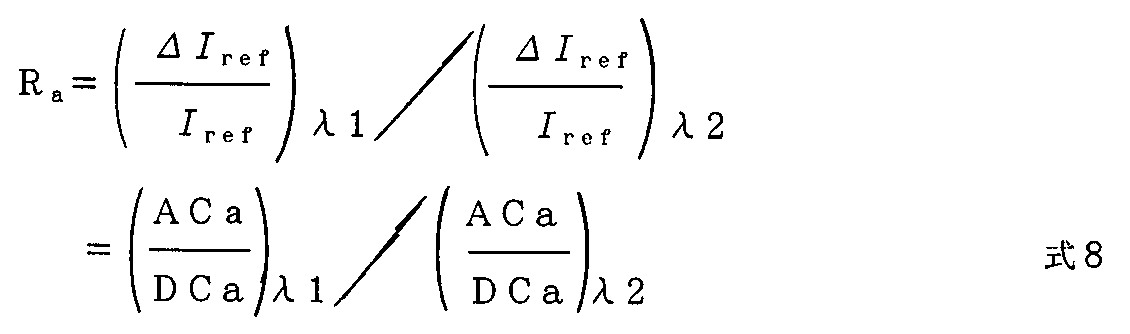
酸素化ヘモグロビン比率(酸素飽和度:SaO2)の各値に対し、この演算結果を、前述の式3を動脈に適用した式8に示すそれぞれの波長λ1及び波長λ2における脈動成分(AC)/オフセット成分(DC)に適用した比Raが算出される。
【数8】
【0028】
式7の静脈血比率(1−β)は、(1−β)70%から1.1(1−β)77%まで増加して、式5の散乱反射光強度Irefが変動する。
【0029】
静脈における酸素化ヘモグロビン比率(酸素飽和度:SvO2)が、動脈より少し低い40%から90%まで変化すると想定して、動脈の場合と同様に、それぞれの酸素飽和度(SvO2)各値に対し、散乱反射光強度Iref と、変動分ΔIrefをそれぞれ演算する。
【0030】
酸素化ヘモグロビン比率(酸素飽和度:SvO2)の各値に対し、この演算結果を、前述の式3に適用した式9に示す比Rvが、同様に算出される。
【数9】
【数10】
【0031】
図1は、本発明の非観血動静脈酸素飽和度測定装置の一実施形態の構成を示すブロック図である。
【0032】
本実施形態は、大きくは、センサ部1と、動脈血処理部2と、静脈血処理部3と、酸素飽和度算定部4と、本発明の非観血動静脈酸素飽和度測定装置の各処理のタイミングと制御を行う制御部5とから構成される。
【0033】
センサ部1は、例えば指先または耳朶などの体表11に装着される2個の発光素子12a、12bと受光素子13とを有するセンサ14と、制御部5のタイミング発生手段からのタイミング信号により発光素子12a、12bを駆動するLED駆動手段15とから成る。
【0034】
動脈血処理部2は、受光素子13に接続される増幅器16と、この増幅器16の出力が入力され、前記タイミング信号により2との出力をする同期検波手段17と、この2つの出力をそれぞれの入力とし、前記タイミング信号の1/2に分周する手段22からのタイミングでこの入力をサンプリングする、2つの脈動サンプリング・ホールド手段18−1、18−2と、この脈動サンプリング・ホールド手段に接続される2つの脈動最大・最小値検出手段19−1、19−2と、この脈動最大・最小値検出手段に接続される2つの脈動率演算手段20−1、20−2と、この2つの脈動率演算手段のそれぞれの出力を入力とする脈動率比Ra演算手段21とから構成される。また、静脈処理部3は、脈動サンプリング・ホールド手段18−1、18−2の出力をそれぞれの入力とする2つの脈波除去ローパスフィルタ23−1、23−2と、この脈波除去ローパスフィルタに接続される2つの変動最大・最小値検出手段24−1、24−2と、この変動最大・最小値検出手段に接続される2つの変動率演算手段25−1、25−2と、この2つの変動率演算手段のそれぞれの出力を入力とする変動率比Rv演算手段26とから構成される。
【0035】
酸素飽和度算出部4は、酸素飽和度検量線算出手段27により予め算出された動脈血・静脈血酸素飽和度検量線データの蓄積手段28と、これに接続されて、前記脈動率比Ra演算手段21の出力、及び前記変動率比Rv演算手段26の出力が入力される酸素飽和度算定手段29と、算出した動脈血、及び静脈血の酸素飽和度31、32の表示手段30とにより構成される。
【0036】
さらに、制御部5は、本実施形態の各手段の連携を制御し、また、本実施形態が検知したり、演算した結果をデータ記憶手段33に書き込む制御を行うシステム制御手段34と、この制御手段より制御されるタイミング発生手段35とから構成される。
【0037】
上述の構成による、本実施形態の動作を図を用いて詳細に説明する。
図2(a)は、本実施形態で使用するセンサを生体に装着する面から見た正面図であり、同図(b)は、このセンサの何れかの発行素子を点灯して、受光素子が検知する散乱光強度を模式的に示す図である。
【0038】
図1に示すセンサ14に内蔵される発行素子12a、12b及び受光素子13は、図2(a)に示すように、発行素子12a、12bのそれぞれが、受光素子13に対し等距離ρとなるように配置されて、生体に装着される。この等距離ρは、生体内各所からの散乱光が再び体表まで透過するのに十分な距離であり、かつ発光素子からの直接の光が受光素子に検知されないように隔てる距離であり、例えば本実施形態では5mmとしている。また発光素子12a、12bは、図6に示す血中ヘモグロビンの吸光特性の等吸点(波長約800nm)より短い波長λ1と長い波長λ2の発光をするもの、またはフィルタにより前記波長が設定されたものである。本実施形態では、発光素子12aが波長λ1:750nmに、発光素子12bが波長λ2:830nmに設定される。
【0039】
タイミング発生手段35からのLED駆動信号F0(周波数f0)が、LED駆動手段15を介して、発光素子12a、12bを交互に駆動する。すなわち、発光素子12a、12bはそれぞれT0(=1/f0)秒間交互に点灯して、その点灯周波数はf0/2である。なお、周波数f0は、概ね20Hzから50Hzの範囲に設定される。
【0040】
この発光素子12a、12bから交互に生体に放射されたそれぞれ波長λ1またはλ2の光が、生体組織、静脈血、及び動脈血で散乱、透過して受光素子13に検知され、散乱光受光信号として増幅手段16で電気的増幅して出力される。
【0041】
図2(b)に、この出力を模式的に示した。この図において、散乱光の透過の様子を理解しやすくするため、透過する領域を区分して示したが、検知し散乱光受光信号ではそれらが混在しており、心拍に同期する動脈の拍動が、呼吸により圧迫される静脈の呼吸性変動に重畳した波形として検知される。特に、同図には静脈の信号成分として表示する区分線は、拍動成分を除去したエンベロープ(包絡線)成分として検出されるものを模式的に示す。また同図では、煩雑になるので微細な表示をしないが、この散乱光受光信号は、前述のそれぞれ波長λ1またはλ2の透過光が交互に検知され連続するものであり、それぞれの波長における透過吸光係数が微小に異なるので、T0(=1/f0)秒間毎の段差を有する波形であるが、これも模式的にこの段差を省略して図示している。
【0042】
増幅手段16から出力される散乱光受光信号は、同期検波手段17に入力されて、この同期検波手段17において、散乱光受光信号をLED駆動信号F0及びこの信号F0の位相を反転(T0こ位相遅れ)した信号F0'により直交検波して、波長λ1に関わる散乱光受光信号S1、及び波長λ2に関わる散乱光受光信号S2の2つの矩形波信号に分離される。
【0043】
次に、分離された散乱光受光信号S1、及び散乱光受光信号S2をそれぞれの点灯周波数と同じf0/2でサンプルホールドするサンプリングホールド手段18−1,18−2に入力して、波長λ1光に関わる脈波信号SP1、及び波長λ2光に関わる脈波信号SP2の2つの連続する階段状波形の脈波信号をそれぞれのサンプリングホールド手段が出力する。この脈波信号SP1及び脈波信号SP2は、動脈の拍動に依り生じる脈波であり、図2(b)の動脈の信号成分に対応する。
【0044】
次に、この脈波信号SP1及び脈波信号SP2は、それぞれの最大値/最小値検出手段19−1、19−2に入力される。入力された脈波信号SP1、または脈波信号SP2の大きさが、この最大値/最小値検出手段19−1、19−2において逐次比較されて、図2(b)の時刻t−a1、及び時刻t−a2に対応した、脈波信号SP1及び脈波信号SP2のそれぞれの最大値、最小値が検出されて、波長λ1光に関わる脈波信号SP1の最大値PS1max及び最小値PS1minが脈動率演算手段20−1へ、波長λ2光に関わる脈波信号SP2の最大値PS2max及び最小値PS2minが脈動率演算手段20−2へ入力される。
【0045】
脈動率演算手段20−1、20−2では、それぞれ入力された最大値、最小値の値から、ΔIa=最大値−最小値、及びI0Ia max=最小値とし、式8に示す脈動における変化率が演算される。すなわち、脈動率演算手段20−1から波長λ1光の脈動率値が、脈動率演算手段20−2から波長λ2光の脈動率値がそれぞれ出力される。
【0046】
脈動率演算手段20−1、20−2の出力は、脈動率比Ra演算手段21にそれぞれ入力されて、式3に示す動脈血の比Raが演算され、出力される。
【0047】
なお、このサンプリングホールド手段18−1、18−2が出力する脈波信号SP1及び脈波信号SP2の最大値/最小値は、1心拍動毎にそれらが検出されるので、脈動率比Ra演算手段21からは、前記比Raが心拍動と同じ頻度で出力される。
【0048】
一方、サンプリング・ホールド手段18−1、18−2の出力である、波長λ1光に関わる脈波信号SP1、及び波長λ2光に関わる脈波信号SP2は、脈波除去ローパスフィルタ23−1、23−2にそれぞれ入力されて、概ね0.5Hz以上の脈波成分を除去する。脈波除去ローパスフィルタ23−1、23−2は、波長λ1に関わる散乱光受光信号S1、及び波長λ2に関わる散乱光受光信号S2の基線の変動、すなわち呼吸により圧迫されてその流量が変動する静脈血の変動をそれぞれ抽出して、波長λ1に関わる呼吸性変動信号SR1、及び波長λ2に関わる呼吸性変動信号SR2としてそれぞれ出力する。
【0049】
脈波除去ローパスフィルタ23−1、23−2から出力された呼吸性変動信号SR1、及び呼吸性変動信号SR2は、呼吸性変動信号の変動最大・最小値検出手段24−1、24−2にそれぞれ入力される。入力された呼吸性変動信号SR1、及び呼吸性変動信号SR2の大きさが、それぞれの変動最大値・最小値検出手段24−1、24−2において逐次比較されて、図2(b)の時刻t−v1、及び時刻t−v2に対応した、呼吸性変動信号SR1、及び呼吸性変動信号SR2のそれぞれの最大値、最小値が検出されて、波長λ1光に関わる呼吸性変動信号SR1の最大値SR1max及び最小値SR1minが変動率演算手段25−1へ、波長λ2光に関わる呼吸性変動信号SR2の最大値SR2max及び最小値SR2minが変動率演算手段25−2へ入力される。
【0050】
変動率演算手段25−1、25−2では、それぞれ入力された最大値、最小値の値から、ΔIV=最大値−最小値、及びI0IV max=最小値とし、式9に示す呼吸性静脈変動における変化率が演算される。すなわち、変動率演算手段25−1から波長λ1光の変動率値が、変動率演算手段25−2から波長λ2光の変動率値がそれぞれ出力される。
【0051】
変動率演算手段25−1、25−2の出力は、変動率比Rv演算手段26にそれぞれ入力されて、式3に示す静脈血の比Rvが演算され、出力される。
【0052】
なお、この脈波除去ローパスフィルタ23−1、23−2が出力する呼吸性変動信号SR1、及び呼吸性変動信号SR2は呼吸性の変動をするため、脈動率比Ra演算手段21から出力の頻度に比べて、変動率比Rv演算手段26からの出力は1/5から1/10の頻度になる。
【0053】
酸素飽和度算出部4の酸素飽和度検量線算出手段27では、式5に示す理論的散乱反射光強度を、本実施形態のセンサ形状、放射光の波長、及び生体の組織/血液、動脈血/静脈血の構成比等のデータに基いて予めシミュレーションし、算定された動脈血・静脈血酸素飽和度検量線データ28が、システム制御手段34の制御の下にデータ記憶手段33に記憶される。酸素飽和度算定手段29は、脈動率比Ra演算手段21から動脈血の比Raが出力されと、データ記憶手段33に記憶された酸素飽和度検量線データ28の動脈血データを参照して、比Raに対応する酸素飽和度値を読み出して表示装置30に出力する。同じく、酸素飽和度算定手段29は、変動率比Rv演算手段26から静脈血の比Rvが出力されと、酸素飽和度検量線データ28の静脈血データを参照して、比Rvに対応する酸素飽和度値を読み出して表示装置30に出力する。表示手段30は、動脈血酸素飽和度値31及び静脈血酸素飽和度値32を表示器に表示する。
【0054】
なお、検量線データが式4に示す関係式、または他の関係式の係数として記憶されている時は、比Rの値をその関係式に算入して酸素飽和度を算定しても良い。
【0055】
前述のように、動脈血の比Raの出力頻度が、静脈血の比Rvの出力頻度より多いため、動脈血酸素飽和度値の表示のタイミングを静脈血酸素飽和度値の表示に合わせて、次回の表示タイミングまでに逐次算出された動脈血酸素飽和度値を蓄積し、平均値算出などの処理をして表示することは、当業者の設計の範囲で行われる。
【0056】
また、サンプリングホールド手段18−1、18−2が出力する脈波信号SP1及び脈波信号SP2の最大値/最小値を検出して、動脈血の比Raが出力されるまでの手順、動脈血の比Raの演算と同様に、呼吸性変動信号SR1、及び呼吸性変動信号SR2の最大値/最小値を検出した後、動脈血の比Raが出力されるまでの手順も、前述のようにそれぞれの手段で行う以外に、検知した最大値及び最小値のデータを、システム制御手段34が制御するデータ記憶手段33に記憶させて、その記憶したデータを基に、システム制御手段34の備える演算機能により演算しても良い。
【0057】
上述のように、本実施形態によれば、体表に発光素子と受光素子を備えるセンサを装着して、従来使用されていたカフ等の圧迫を行うこと無く、無侵襲的かつ非観血的に、動脈血と静脈血の酸素飽和度をそれぞれほぼ同時に、測定し表示することができる。
【0058】
図4は、本実施形態の酸素飽和度検量線算定手段27における検量線シミュレーションと実測した酸素飽和度の関係を示すグラフであり、同図(a)は動脈血について、同図(b)は静脈血について示してある。
【0059】
式5に示す理論的散乱反射光強度を、生体の組織/血液の構成比を組織:血液=97:3(%)に、動脈血/静脈血の構成比を動脈:静脈=30:70(%)に設定し、動脈の拍動成分が、動脈血に対し30%、静脈における変動は、静脈血に対し10%として、式5の散乱光透過光強度Iref及びΔIrefを算出して、脈動率比Ra(動脈血)及び変動率比Rv(静脈血)をシミューレーションした。図4は、シミュレーション結果(図4の実線:ただし散乱係数μs'の変化範囲0.8〜1.4mm−1)と実測した酸素飽和度(図4の白丸印)データが、動脈血及び静脈血のいずれにおいても、両者の一致が良く、校正を必要としない適正な生体側条件の設定が成された事を示している。
すなわち、従来の光学的酸素飽和度測定装置においては、検量線特性を他の基準のとなる酸素飽和度測定装置と並行測定を行って校正する必要があったが、本発明の非観血動静脈酸素飽和度測定装置では、センサ形状、使用波長、生体の条件を基に、理論的散乱光透過光強度をシミュレーションし、検量線データを作成することにより、校正を不要とすることができる。
【0060】
【発明の効果】
以上、説明したように本発明の非観血動静脈酸素飽和度測定装置は、動脈血及び静脈血をカフ等の補助機構によらず、同一のセンサにより、非観血的に生理的には略同時に、動脈血及び静脈血のそれぞれの酸素飽和度を測定できる。また、標準の酸素飽和度測定装置による測定値の校正を必要としない。
【図面の簡単な説明】
【図1】本発明の一実施形態の構成を示すブロック図。
【図2】本実施形態で使用するセンサの正面図とセンサの受光素子が検知する散乱光強度を模式的に示す図。
【図3】動脈血の酸素飽和度SaO2と比Ra及び静脈血の酸素飽和度SvO2と比Rvとの関係のシミュレーション結果を示すグラフ。
【図4】本実施形態の検量線シミュレーションと実測酸素飽和度の関係を示すグラフ。
【図5】生体内の組織層、静脈血、及び動脈血層を透過する光強度を示す模式図。
【図6】血中ヘモグロビンの吸収係数特性を示すグラフ。
【符号の説明】
1・・・センサ部、
2・・・動脈血処理部、
3・・・静脈血処理部、
4・・・酸素飽和度算出部、
5・・・制御部、
11・・・生体、
12a、12b・・・発光素子、
13・・・受光素子、
14・・・センサ、
15・・・LED駆動手段、
16・・・増幅手段、
17・・・同期検波手段、
18―1、18−2・・・サンプリング・ホールド手段、
19−1、19−2・・・最大値/最小値検出手段、
20−1、20−2・・・脈動率演算手段、
21・・・脈動率比Ra演算手段、
22・・・1/2分周手段、
23−1、23−2・・・脈波除去ローパスフィルタ、
24−1、24−2・・・変動最大・最小値検出手段、
25−1、25−2・・・変動率演算手段、
26・・・変動率比Rv演算手段、
27・・・酸素飽和度検量線算出手段、
28・・・酸素飽和度検量線データ、
29・・・酸素飽和度算定手段、
30・・・表示手段、
31・・・動脈血酸素飽和度、
32・・・静脈血酸素飽和度、
33・・・データ記憶手段、
34・・・システム制御手段、
35・・・タイミング発生手段。[0001]
BACKGROUND OF THE INVENTION
The present invention relates to an arteriovenous oxygen saturation measuring apparatus that noninvasively measures blood oxygen saturation in arteries and veins.
[0002]
[Prior art]
Measuring the oxygen saturation of a living tissue is very important for knowing the general condition of the patient, and a lot of information can be obtained by combining it with continuous measurements or other measured values of the living body. Furthermore, if not only arterial blood but also venous blood can be measured simultaneously, it is possible to know the activity state of the tissue such as oxygen metabolism.
[0003]
At present, for the measurement of arterial blood or venous blood oxygen saturation, an invasive measurement method for collecting blood and a non-invasive measurement method using an optical technique from the body surface are usually performed.
[0004]
As a method for noninvasively measuring the oxygen saturation of arterial blood, a pulse oximeter method using a pulsating component of an artery is widely used by utilizing the fact that only the artery pulsates due to the pulsation of the heart. On the other hand, there is only an invasive method for measuring venous blood oxygen saturation, and a method for noninvasively measuring venous blood oxygen saturation has not been established.
[0005]
Several attempts have been made to measure the oxygen saturation of tissue or arteriovenous blood at the same time, and venous blood and arterial blood cannot be measured separately, and only the oxygen saturation of the entire tissue can be measured ( JP 2000-107157), an optical sensor attached to the tip of a bronchial catheter, and invasively measuring mixed venous blood in the pulmonary artery (JP 11-244264) has been devised. In addition, according to the volume vibration method or the volume compensation method using a cuff (JP-A-2-305555, JP-A-6-63024, JP-A-1-146524), the subject is accompanied by invasiveness such as pressurization load and congestion. In addition, there is a problem that is not applicable to continuous measurement because the measurement site is limited due to the cuff attachment, or a pressurization pump needs to be provided.
[0006]
The pulse oximeter method widely applied as a conventional method for noninvasively measuring the oxygen saturation of arterial blood is a measurement method based on Lambert-Bear's law, and its principle is used. Is described below.
[0007]
As shown in FIG. 5, the light emitted from the body surface into the living body, scattered in the body, and detected again on the body surface passes through the tissue layer, venous blood, and arterial blood layer, and the transmittance is expressed by
[Expression 1]
[0008]
Change ΔI of detected light intensity due to arterial pulsation in FIG.dIaPaying attention to the above, the rate of change in transmission is expressed by
[Expression 2]
[0009]
On the other hand, as shown in FIG. 6, the absorption spectra of oxygenated hemoglobin (
[0010]
Wavelength λ shorter than this absorption point absorption wavelength1, And long wavelength λ2Taking the ratio of the pulse wave component / offset component of equation (2) observed in (3), this is expressed as ratio R as shown in equation (3).
[Equation 3]
[Expression 4]
![]()
[0011]
[Problems to be solved by the invention]
As described above, in conventional oxygen saturation measurement, arterial blood is the target of non-invasive measurement, and venous blood is mainly based on an invasive technique. However, non-invasive measurement of venous blood requires venous compression with a cuff, etc., and there is a problem in performing simultaneous measurement, such as by limiting the measurement site by using different methods such as congestion. there were.
[0012]
Further, in the blood oxygen saturation measuring apparatus by the pulse oximeter method which is a noninvasive oxygen saturation measuring method, the constants A and B of the apparatus related to the measurement characteristics are used as the reference oxygen saturation measurement. It was necessary to carry out parallel measurement with a measuring instrument and calibrate.
[0013]
The present invention has been made in view of the above-described problems, and arterial blood and venous blood are non-invasively and physiologically almost simultaneously with the same sensor regardless of an auxiliary mechanism such as a cuff. It is an object of the present invention to provide a noninvasive arteriovenous oxygen saturation measuring device that can measure the oxygen saturation of the blood vessel and does not require calibration of the measured value using a standard oxygen saturation measuring device.
[0014]
[Means for Solving the Problems]
The noninvasive arteriovenous oxygen saturation measuring device of the present invention detects a light source for irradiating a living body with light having different first and second wavelengths, and light transmitted through or scattered by the living body. And a detector that is supplied with an output signal of the receiver and outputs a first output signal related to the first wavelength and a second output signal related to the second wavelength, and the detector The first output value of the first maximum value / minimum value detection means for outputting the maximum value and the minimum value of the output signal, and the output value of the first maximum value / minimum value detection means The first pulsation rate calculating means for calculating the pulsation rate, and the second output signal of the detection means are supplied, and the second maximum value / minimum value for outputting the maximum value and the minimum value of the output signal. The detection means and the output value of the second maximum value / minimum value detection means are input, A second pulsation rate calculating means for calculating the pulsation rate, and a ratio between the output value from the first pulsation rate calculating means and the output value from the second pulsation rate calculating means, and from these values, arterial blood The first oxygen saturation calculating means for calculating the oxygen saturation of the first output signal, and a signal obtained by removing a high frequency component from the first output signal of the detecting means are supplied, and a third maximum is outputted. From the value / minimum value detection means, the first fluctuation rate calculation means for calculating the fluctuation rate by inputting the output value of the third maximum value / minimum value detection means, and the second output signal of the detection means A signal from which a high frequency component is removed is supplied, and a fourth maximum value / minimum value detecting means for outputting the maximum value and the minimum value thereof, and an output value of the fourth maximum value / minimum value detecting means are inputted and fluctuated. A second variation rate computing means for computing a rate, and the first variation rate computing means And a second oxygen saturation calculating means for outputting the oxygen saturation of venous blood from these values. It is a feature.
[0015]
The noninvasive arteriovenous oxygen saturation measuring device of the present invention includes a light source for irradiating a living body with light having different first and second wavelengths, and light transmitted through the living body or scattered by the living body. And a detector for outputting a first output signal relating to the first wavelength and a second output signal relating to the second wavelength, to which an output signal of the light receiver is supplied, and First maximum / minimum value detection means for supplying the maximum value and minimum value of the output signal to which the first output signal of the detection means is supplied, and the output of the first maximum / minimum value detection means The first pulsation rate calculating means for calculating the pulsation rate and the second output signal of the detection means are supplied, and the maximum / minimum value of the output signal is output. The minimum value detection means and the output value of the second maximum value / minimum value detection means are input. The second pulsation rate calculating means for calculating the pulsation rate, and the third maximum value for supplying the maximum value and the minimum value, which are supplied with a signal obtained by removing a high frequency component from the first output signal of the detection means. / Minimum value detecting means, a first fluctuation rate calculating means for calculating the fluctuation rate by inputting the output value of the third maximum value / minimum value detecting means, and a second output signal of the detecting means, the high frequency The fourth maximum value / minimum value detection means for supplying a signal from which the component is removed and outputting the maximum value and the minimum value, and the output value of the fourth maximum value / minimum value detection means are input, and the variation rate The ratio of the output value from the second fluctuation rate calculating means, the first pulsation rate calculating means and the output value from the second pulsation rate calculating means is input, and from these values, the oxygen of arterial blood A first oxygen saturation calculating means for calculating saturation; and the first variation rate A ratio of an output value from the calculating means and an output value from the second fluctuation rate calculating means is input, and a second oxygen saturation calculating means for outputting the oxygen saturation of venous blood from these values, The first oxygen saturation calculating means includes an oxygen saturation calibration relational expression obtained from a light diffusion equation, and an output value from the first pulsation rate calculating means and an output from the second pulsation rate calculating means. The oxygen saturation of arterial blood with respect to the ratio of the values is calculated and output by the oxygen saturation calibration relational expression, and the second oxygen saturation calculating means outputs the output value from the first fluctuation rate calculating means and the The oxygen saturation level of venous blood relative to the ratio of the output values from the second fluctuation rate calculating means is calculated by the oxygen saturation calibration relational expression and output.
[0016]
Furthermore, in the noninvasive arteriovenous oxygen saturation measuring apparatus of the present invention, the oxygen saturation calibration relational expression is set for each of the first and second wavelengths with respect to a plurality of preset oxygen saturations. Transmission absorption coefficient depending on biological tissue / blood composition ratio and arterial blood / venous blood composition ratio, and maximum / minimum value of scattered transmitted light intensity obtained from light diffusion equation with the distance between light source and light receiver as a variable, Calculate according to the maximum or minimum of arterial blood volume or venous blood volume, calculate the pulsation rate of arteries or variability of veins from this calculated value, and from the ratio of pulsation rate of each wavelength or the ratio of variability It is a formula for calculating oxygen saturation.
[0017]
Furthermore, in the noninvasive arteriovenous oxygen saturation measuring device of the present invention, the first and second oxygen saturation calculation means are configured to perform the first and second oxygen saturations with respect to a plurality of preset oxygen saturations. The maximum value of the scattered transmitted light intensity obtained from the light diffusion equation with the variable of the distance between the light source and the receiver, and the transmission / absorption coefficient depending on the tissue / blood composition ratio and the arterial / venous blood composition ratio for each wavelength -Calculate the minimum value corresponding to the maximum or minimum of arterial blood volume or venous blood volume, calculate the pulsation rate of the artery and the fluctuation rate of the vein from this calculated value, the ratio of the pulsation rate of each wavelength, or The variation rate ratio and the oxygen saturation are accumulated in the data storage means in the form of reference data as oxygen saturation calibration curve data.
[0018]
Furthermore, in the noninvasive arteriovenous oxygen saturation measuring device of the present invention, the first and second oxygen saturation calculating means are the biological tissue / blood of the biological condition applied to the calculation of the scattered transmitted light intensity. In the biological tissue: blood = α: (1−α) as the component ratio, α is set to any value between 95% and 98%, and arterial blood: venous blood = β: (1−− In β), β is set to any value between 20% and 40%, and the arterial blood volume or venous blood volume is changed to calculate the oxygen saturation calibration curve.
[0019]
Furthermore, in the noninvasive arteriovenous oxygen saturation measuring device of the present invention, the light source includes a first light source that emits light of the first wavelength, and a second light source that emits light of the second wavelength. The first wavelength is shorter than the isosbestic wavelength near 800 nm, the second wavelength is longer than the isosbestic wavelength near 800 nm, and the receiver is It is provided at a position equidistant from the second light source.
[0020]
DETAILED DESCRIPTION OF THE INVENTION
First, in this embodiment, the principle of a mode of measuring the oxygen saturation level of blood in relation to the light of different wavelengths being emitted into the body and detected again on the body surface will be described.
[0021]
In a conventional oxygen saturation measuring device using light, the property of light emitted to the living body is handled as backscattered light. The inventors have focused on the analysis of scattered light, which aims to theoretically develop the properties of light in the living body, and find a theoretical solution from the light diffusion equation to obtain the scattered reflected light intensity. Repeated research.
[0022]
In the analysis of this scattered light (reference: Thomas J. Farrell & Michael S. Patterson: Medical Physics, Vol.19, No.4, pp879-888, Jul./Aug.1992), the light emitted from the body surface After being incident on the living body, the light is scattered by each part of the living tissue, detected by the light receiving element located at a distance ρ from the light emitting element, and scattered reflected light intensity IrefIs obtained by the equation shown in
[Equation 5]
[0023]
The inventors conducted further research and consideration on the
[0024]
When the composition ratio of the living tissue and blood is expressed as tissue: blood = α: (1−α), the absorption coefficient μ of the living bodyaIsLet μat and μab be the respective absorption coefficients in tissue and blood,It can be expressed by Equation 6.
[Formula 6]
[Expression 7]
![]()
[0025]
In the simulation, the arterial pulsation component is about 30% of the arterial blood, so the arterial blood ratio β in Equation 7 increases from 30% β to 39% 1.3β, and the scattered reflected light intensity in
[0026]
Oxygenated hemoglobin ratio in the artery (oxygen saturation: SaO2) Varies from 50% to 100%, and for each of the values, a predetermined wavelength λ is set.1And wavelength λ2For the above arterial blood ratios of 30% β and 39% 1.3β, the scattered reflected light intensity I of
[0027]
Oxygenated hemoglobin ratio (oxygen saturation: SaO2) For the respective values of λ), the calculation result is expressed as the wavelength λ shown in Equation 8 obtained by applying Equation 3 to the artery.1And wavelength λ2Ratio R applied to pulsation component (AC) / offset component (DC)aIs calculated.
[Equation 8]
[0028]
The venous blood ratio (1-β) in Equation 7 increases from (1-β) 70% to 1.1 (1-β) 77%, and the scattered reflected light intensity I in
[0029]
Oxygenated hemoglobin ratio in the vein (oxygen saturation: SvO2) Vary from 40% to 90%, which is slightly lower than the artery, and as with the artery, the respective oxygen saturation (SvO)2) For each value, scattered light intensity Iref When,Variation ΔIrefAre respectively calculated.
[0030]
Oxygenated hemoglobin ratio (oxygen saturation: SvO2) For each value, the ratio R shown in Equation 9 applied to Equation 3 above.vAre similarly calculated.
[Equation 9]
[Expression 10]
[0031]
FIG. 1 is a block diagram showing a configuration of an embodiment of a noninvasive arteriovenous oxygen saturation measuring apparatus according to the present invention.
[0032]
In the present embodiment, the processing of the
[0033]
The
[0034]
The arterial
[0035]
The oxygen saturation calculation unit 4 is connected to the arterial blood / venous blood oxygen saturation calibration curve data accumulating means 28 calculated in advance by the oxygen saturation calibration curve calculating means 27, and is connected to the pulsation rate ratio R.aThe output of the calculation means 21 and the fluctuation rate ratio RvIt comprises an oxygen saturation calculation means 29 to which the output of the calculation means 26 is inputted, and a display means 30 for the calculated oxygen saturation 31 and 32 of arterial blood and venous blood.
[0036]
Further, the
[0037]
The operation of the present embodiment having the above-described configuration will be described in detail with reference to the drawings.
FIG. 2A is a front view of the sensor used in the present embodiment as viewed from the surface where the sensor is attached to the living body, and FIG. It is a figure which shows typically the scattered light intensity which detects.
[0038]
The
[0039]
LED drive signal F from timing generator 350(Frequency f0) Alternately drive the
[0040]
Wavelengths λ emitted from the
[0041]
FIG. 2 (b) schematically shows this output. In this figure, in order to make it easy to understand the state of transmission of scattered light, the transmission region is shown separately. However, the detected and scattered light reception signals are mixed, and the pulsation of the artery synchronized with the heartbeat Is detected as a waveform superimposed on the respiratory change of the vein compressed by respiration. In particular, in the same figure, the dividing line displayed as the signal component of the vein schematically shows what is detected as the envelope (envelope) component from which the pulsation component is removed. Also, in this figure, since the display becomes complicated, fine display is not performed.1Or λ2Are transmitted and detected alternately, and the transmission / absorption coefficient at each wavelength is slightly different.0(= 1 / f0) Although the waveform has a step every second, this step is also schematically omitted.
[0042]
The scattered light receiving signal output from the amplifying means 16 is input to the synchronous detecting means 17, and the synchronous detecting means 17 converts the scattered light receiving signal into the LED drive signal F.0And this signal F0Invert the phase of (T0This phase lag) signal F0Waveform λ by quadrature detection with '1Scattered light reception signal S1 and wavelength λ related to2Is separated into two rectangular wave signals of the scattered light receiving signal S2 related to the.
[0043]
Next, the separated scattered light reception signal S1 and scattered light reception signal S2 are set to the same lighting frequency as f.0Input to the sampling and holding means 18-1 and 18-2 for sampling and holding at / 2,1Pulse wave signal SP1 related to light and wavelength λ2Each sampling and holding means outputs two continuous stepped pulse wave signals of the pulse wave signal SP2 related to light. The pulse wave signal SP1 and the pulse wave signal SP2 are pulse waves generated by the pulsation of the artery and correspond to the signal components of the artery in FIG.
[0044]
Next, the pulse wave signal SP1 and the pulse wave signal SP2 are input to the respective maximum value / minimum value detecting means 19-1 and 19-2. The magnitudes of the input pulse wave signal SP1 or pulse wave signal SP2 are sequentially compared in the maximum value / minimum value detecting means 19-1 and 19-2, and time t-a1, FIG. And the maximum and minimum values of the pulse wave signal SP1 and the pulse wave signal SP2 corresponding to the time t-a2 are detected, and the wavelength λ1The maximum value PS1max and the minimum value PS1min of the pulse wave signal SP1 related to light are transmitted to the pulsation rate calculating means 20-1 at the wavelength λ.2The maximum value PS2max and the minimum value PS2min of the pulse wave signal SP2 related to light are input to the pulsation rate calculating means 20-2.
[0045]
In the pulsation rate calculating means 20-1, 20-2, ΔI is calculated from the input maximum value and minimum value.a= Maximum value-minimum value and I0Ia max= Minimum value, and the rate of change in pulsation shown in Equation 8 is calculated. That is, from the pulsation rate calculating means 20-1, the wavelength λ1The light pulsation rate value is calculated from the pulsation rate calculating means 20-2 by the wavelength λ.2Light pulsation rate values are output.
[0046]
The output of the pulsation rate calculating means 20-1, 20-2 is the pulsation rate ratio RaThe arterial blood ratio R shown in Equation 3 is input to the calculation means 21.aIs calculated and output.
[0047]
Since the maximum value / minimum value of the pulse wave signal SP1 and the pulse wave signal SP2 output by the sampling hold means 18-1 and 18-2 are detected for each heartbeat, the pulsation rate ratio RaFrom the calculation means 21, the ratio RaIs output at the same frequency as heartbeat.
[0048]
On the other hand, the wavelength λ, which is the output of the sampling and holding means 18-1, 18-2.1Pulse wave signal SP1 related to light and wavelength λ2The pulse wave signal SP2 related to light is input to the pulse wave removal low-pass filters 23-1 and 23-2, respectively, and removes a pulse wave component of approximately 0.5 Hz or more. The pulse wave removal low-pass filters 23-1, 23-2 have a wavelength λ1Scattered light reception signal S1 and wavelength λ related to2The fluctuations of the baseline of the scattered light reception signal S2 related to the light, that is, the fluctuations of venous blood whose flow rate is changed by being compressed by respiration are respectively extracted, and the wavelength λ1Respiratory change signal SR1 and wavelength λ related to2Are respectively output as the respiratory change signal SR2 related to.
[0049]
The respiratory fluctuation signal SR1 and the respiratory fluctuation signal SR2 output from the pulse wave removal low-pass filters 23-1 and 23-2 are supplied to the fluctuation maximum / minimum value detection means 24-1 and 24-2 of the respiratory fluctuation signal. Each is entered. The magnitudes of the input respiratory change signal SR1 and the respiratory change signal SR2 are sequentially compared in the respective fluctuation maximum value / minimum value detecting means 24-1 and 24-2, and the time shown in FIG. The maximum value and the minimum value of the respiratory fluctuation signal SR1 and the respiratory fluctuation signal SR2 corresponding to t-v1 and time t-v2 are detected, and the wavelength λ1The maximum value SR1max and the minimum value SR1min of the respiratory change signal SR1 related to light are transmitted to the change rate calculation means 25-1 at the wavelength λ.2The maximum value SR2max and the minimum value SR2min of the respiratory change signal SR2 related to light are input to the fluctuation rate calculation means 25-2.
[0050]
In the fluctuation rate calculation means 25-1 and 25-2, ΔI is calculated from the input maximum and minimum values.V= Maximum value-minimum value and I0IV max= Minimum value, and the rate of change in respiratory venous fluctuation shown in Equation 9 is calculated. That is, from the fluctuation rate calculating means 25-1, the wavelength λ1The light fluctuation rate value is changed from the fluctuation rate calculating means 25-2 to the wavelength λ.2Light fluctuation rate values are output respectively.
[0051]
The output of the fluctuation rate calculation means 25-1, 25-2 is the fluctuation rate ratio RvThe venous blood ratio R shown in Equation 3 is input to the calculation means 26, respectively.vIs calculated and output.
[0052]
Note that the respiratory fluctuation signal SR1 and the respiratory fluctuation signal SR2 output by the pulse wave removal low-pass filters 23-1 and 23-2 have a respiratory fluctuation, and therefore the pulsation rate ratio RaCompared to the frequency of output from the computing means 21, the fluctuation rate ratio RvThe output from the computing means 26 has a frequency of 1/5 to 1/10.
[0053]
In the oxygen saturation calibration curve calculating means 27 of the oxygen saturation calculating unit 4, the theoretical scattered reflected light intensity shown in
[0054]
When the calibration curve data is stored as a relational expression shown in Expression 4 or a coefficient of another relational expression, the value of the ratio R may be included in the relational expression to calculate the oxygen saturation.
[0055]
As mentioned above, arterial blood ratio RaOutput frequency is venous blood ratio RvSince the output frequency of the arterial blood oxygen saturation value is the same as the venous blood oxygen saturation value display timing, the arterial blood oxygen saturation value calculated sequentially until the next display timing is accumulated and averaged. Display by performing processing such as calculation is performed within the scope of design by those skilled in the art.
[0056]
Further, the maximum value / minimum value of the pulse wave signal SP1 and the pulse wave signal SP2 output by the sampling hold means 18-1 and 18-2 are detected, and the arterial blood ratio R is detected.aProcedure until blood pressure is output, arterial blood ratio RaIn the same manner as in the calculation of the arterial blood ratio R, after detecting the maximum value / minimum value of the respiratory fluctuation signal SR1 and the respiratory fluctuation signal SR2.aAs described above, the procedure until the signal is output is also performed by the respective means as described above, and the detected maximum value and minimum value data are stored in the data storage means 33 controlled by the system control means 34 and stored. Based on the obtained data, the calculation may be performed by a calculation function provided in the system control unit 34.
[0057]
As described above, according to the present embodiment, a sensor including a light emitting element and a light receiving element is attached to the body surface, and a non-invasive and non-invasive method is performed without compressing a conventionally used cuff or the like. In addition, the oxygen saturation levels of arterial blood and venous blood can be measured and displayed almost simultaneously.
[0058]
FIG. 4 is a graph showing the relationship between the calibration curve simulation in the oxygen saturation calibration curve calculating means 27 of this embodiment and the actually measured oxygen saturation. FIG. 4A shows arterial blood and FIG. 4B shows vein. Shown about blood.
[0059]
The theoretical scattered / reflected light intensity shown in
That is, in the conventional optical oxygen saturation measuring device, it was necessary to calibrate the calibration curve characteristics by performing parallel measurement with the oxygen saturation measuring device as another reference. In the venous oxygen saturation measuring device, calibration can be made unnecessary by simulating the theoretical scattered light transmitted light intensity based on the sensor shape, the wavelength used, and the condition of the living body, and creating calibration curve data.
[0060]
【The invention's effect】
As described above, the non-invasive arteriovenous oxygen saturation measuring device of the present invention is substantially non-invasively physiologically non-invasively using the same sensor for arterial blood and venous blood without using an auxiliary mechanism such as a cuff. At the same time, the respective oxygen saturation levels of arterial blood and venous blood can be measured. Moreover, calibration of the measured value by a standard oxygen saturation measuring device is not required.
[Brief description of the drawings]
FIG. 1 is a block diagram showing a configuration of an embodiment of the present invention.
FIG. 2 is a front view of a sensor used in the present embodiment, and a diagram schematically showing scattered light intensity detected by a light receiving element of the sensor.
FIG. 3 Arterial oxygen saturation SaO2And ratio RaAnd venous blood oxygen saturation SvO2And ratio RvIn relation toGraph showing simulation results.
FIG. 4 is a graph showing the relationship between the calibration curve simulation of this embodiment and the actually measured oxygen saturation.
FIG. 5 is a schematic diagram showing the intensity of light transmitted through a tissue layer, venous blood, and arterial blood layer in a living body.
FIG. 6 is a graph showing absorption coefficient characteristics of blood hemoglobin.
[Explanation of symbols]
1 ... sensor part,
2 ... Arterial blood treatment part,
3 ... Venous blood treatment part,
4 ... oxygen saturation calculation unit,
5 ... Control unit,
11 ... living body,
12a, 12b ... light emitting element,
13: Light receiving element,
14 ... sensor,
15 ... LED driving means,
16: Amplifying means,
17 ... Synchronous detection means,
18-1, 18-2 ... Sampling and holding means,
19-1, 19-2 ... Maximum value / minimum value detection means,
20-1, 20-2 ... pulsation rate calculating means,
21 ... Pulsation rate ratio RaComputing means,
22 ... 1/2 frequency dividing means,
23-1, 23-2 ... Pulse wave removal low-pass filter,
24-1, 24-2 ... Fluctuation maximum / minimum value detecting means,
25-1, 25-2 ... Fluctuation rate calculating means,
26: Fluctuation ratio RvComputing means,
27 ... oxygen saturation calibration curve calculating means,
28 ... Oxygen saturation calibration curve data,
29 ... oxygen saturation calculating means,
30 ... display means,
31 ... arterial blood oxygen saturation,
32 ... Venous blood oxygen saturation,
33 Data storage means
34 ... System control means,
35: Timing generating means.
Claims (7)
前記生体を透過し、または前記生体で散乱した光を検出する受光器と、
この受光器の出力信号が供給され、前記第1の波長に関わる第1の出力信号及び前記第2の波長に関わる第2の出力信号を出力する検波手段と、
この検波手段の前記第1の出力信号が供給され、その出力信号の最大値及び最小値を出力する第1の最大値/最小値検出手段と、
この第1の最大値/最小値検出手段の出力値が入力され、脈動率を演算する第1の脈動率演算手段と、
前記検波手段の第2の出力信号が供給され、その出力信号の最大値及び最小値を出力する第2の最大値/最小値検出手段と、
この第2の最大値/最小値検出手段の出力値が入力され、脈動率を演算する第2の脈動率演算手段と、
前記第1の脈動率演算手段からの出力値と前記第2の脈動率演算手段からの出力値の比が入力され、これらの値から動脈血の酸素飽和度を算定する第1の酸素飽和度算定手段と、
前記検波手段の第1の出力信号から高周波成分を除去した信号が供給され、その最大値及び最小値を出力する第3の最大値/最小値検出手段と、
この第3の最大値/最小値検出手段の出力値が入力され、変動率を演算する第1の変動率演算手段と、
前記検波手段の第2の出力信号から高周波成分を除去した信号が供給され、その最大値及び最小値を出力する第4の最大値/最小値検出手段と、
この第4の最大値/最小値検出手段の出力値が入力され、変動率を演算する第2の変動率演算手段と、
前記第1の変動率演算手段からの出力値と前記第2の変動率演算手段からの出力値の比が入力され、これらの値から静脈血の酸素飽和度を出力する第2の酸素飽和度算定手段とを備えたことを特徴とする非観血動静脈酸素飽和度測定装置。A light source for irradiating the living body with light of different first and second wavelengths;
A light receiver that detects light transmitted through the living body or scattered by the living body;
A detector that is supplied with an output signal of the light receiver and outputs a first output signal related to the first wavelength and a second output signal related to the second wavelength;
First maximum / minimum value detecting means for supplying the first output signal of the detection means and outputting the maximum value and the minimum value of the output signal;
An output value of the first maximum value / minimum value detection means, and a first pulsation rate calculating means for calculating a pulsation rate;
Second maximum value / minimum value detection means for supplying a second output signal of the detection means and outputting a maximum value and a minimum value of the output signal;
Second pulsation rate calculating means for inputting the output value of the second maximum value / minimum value detecting means and calculating the pulsation rate;
The ratio of the output value from the first pulsation rate calculating means and the output value from the second pulsation rate calculating means is inputted, and the first oxygen saturation calculation for calculating the oxygen saturation of arterial blood from these values Means,
A third maximum value / minimum value detection means for receiving a signal obtained by removing a high frequency component from the first output signal of the detection means and outputting the maximum value and the minimum value;
An output value of the third maximum value / minimum value detecting means is inputted, and a first fluctuation rate calculating means for calculating the fluctuation rate;
A fourth maximum value / minimum value detection means for supplying a signal obtained by removing a high frequency component from the second output signal of the detection means and outputting a maximum value and a minimum value thereof;
A second fluctuation rate calculating means for inputting the output value of the fourth maximum value / minimum value detecting means and calculating the fluctuation rate;
A ratio of an output value from the first fluctuation rate calculation means and an output value from the second fluctuation rate calculation means is input, and a second oxygen saturation level that outputs the oxygen saturation level of venous blood from these values. A non-invasive arteriovenous oxygen saturation measuring device comprising a calculating means.
前記生体を透過し、または前記生体で散乱した光を検出する受光器と、
この受光器の出力信号が供給され、前記第1の波長に関わる第1の出力信号及び前記第2の波長に関わる第2の出力信号を出力する検波手段と、
この検波手段の前記第1の出力信号が供給され、その出力信号の最大値及び最小値を出力する第1の最大値/最小値検出手段と、
この第1の最大値/最小値検出手段の出力値が入力され、脈動率を演算する第1の脈動率演算手段と、
前記検波手段の第2の出力信号が供給され、その出力信号の最大値及び最小値を出力する第2の最大値/最小値検出手段と、
この第2の最大値/最小値検出手段の出力値が入力され、脈動率を演算する第2の脈動率演算手段と、
前記検波手段の第1の出力信号から高周波成分を除去した信号が供給され、その最大値及び最小値を出力する第3の最大値/最小値検出手段と、
この第3の最大値/最小値検出手段の出力値が入力され、変動率を演算する第1の変動率演算手段と、
前記検波手段の第2の出力信号から高周波成分を除去した信号が供給され、その最大値及び最小値を出力する第4の最大値/最小値検出手段と、
この第4の最大値/最小値検出手段の出力値が入力され、変動率を演算する第2の変動率演算手段と、
前記第1の脈動率演算手段からの出力値と前記第2の脈動率演算手段からの出力値の比が入力され、これらの値から動脈血の酸素飽和度を算定する第1の酸素飽和度算定手段と、
前記第1の変動率演算手段からの出力値と前記第2の変動率演算手段からの出力値の比が入力され、これらの値から静脈血の酸素飽和度を出力する第2の酸素飽和度算定手段とを備え、
前記第1の酸素飽和度算定手段は、光拡散方程式から求めた酸素飽和度検量関係式を備え、前記第1の脈動率演算手段からの出力値と前記第2の脈動率演算手段からの出力値の比に対する動脈血の酸素飽和度を、前記酸素飽和度検量関係式により算定して出力し、前記第2の酸素飽和度算定手段は、前記第1の変動率演算手段からの出力値と前記第2の変動率演算手段からの出力値の比に対する静脈血の酸素飽和度を、前記酸素飽和度検量関係式により算定して出力することを特徴とする非観血動静脈酸素飽和度測定装置。A light source for irradiating the living body with light of different first and second wavelengths;
A light receiver that detects light transmitted through the living body or scattered by the living body;
A detector that is supplied with an output signal of the light receiver and outputs a first output signal related to the first wavelength and a second output signal related to the second wavelength;
First maximum / minimum value detecting means for supplying the first output signal of the detection means and outputting the maximum value and the minimum value of the output signal;
An output value of the first maximum value / minimum value detection means, and a first pulsation rate calculating means for calculating a pulsation rate;
Second maximum value / minimum value detection means for supplying a second output signal of the detection means and outputting a maximum value and a minimum value of the output signal;
Second pulsation rate calculating means for inputting the output value of the second maximum value / minimum value detecting means and calculating the pulsation rate;
A third maximum value / minimum value detection means for receiving a signal obtained by removing a high frequency component from the first output signal of the detection means and outputting the maximum value and the minimum value;
An output value of the third maximum value / minimum value detecting means is inputted, and a first fluctuation rate calculating means for calculating the fluctuation rate;
A fourth maximum value / minimum value detection means for supplying a signal obtained by removing a high frequency component from the second output signal of the detection means and outputting a maximum value and a minimum value thereof;
A second fluctuation rate calculating means for inputting the output value of the fourth maximum value / minimum value detecting means and calculating the fluctuation rate;
The ratio of the output value from the first pulsation rate calculating means and the output value from the second pulsation rate calculating means is inputted, and the first oxygen saturation calculation for calculating the oxygen saturation of arterial blood from these values Means,
The ratio of the output value from the first fluctuation rate calculation means and the output value from the second fluctuation rate calculation means is inputted, and the second oxygen saturation that outputs the oxygen saturation of venous blood from these values A calculation means,
The first oxygen saturation calculating means includes an oxygen saturation calibration relational expression obtained from a light diffusion equation, and an output value from the first pulsation rate calculating means and an output from the second pulsation rate calculating means. The oxygen saturation of arterial blood with respect to the ratio of the values is calculated and output by the oxygen saturation calibration relational expression, and the second oxygen saturation calculating means outputs the output value from the first fluctuation rate calculating means and the A non-invasive arteriovenous oxygen saturation measuring apparatus which calculates and outputs the oxygen saturation of venous blood with respect to the ratio of the output values from the second fluctuation rate calculating means by the oxygen saturation calibration relational expression .
Priority Applications (1)
| Application Number | Priority Date | Filing Date | Title |
|---|---|---|---|
| JP2002167666A JP4040913B2 (en) | 2002-06-07 | 2002-06-07 | Noninvasive arteriovenous oxygen saturation measuring device |
Applications Claiming Priority (1)
| Application Number | Priority Date | Filing Date | Title |
|---|---|---|---|
| JP2002167666A JP4040913B2 (en) | 2002-06-07 | 2002-06-07 | Noninvasive arteriovenous oxygen saturation measuring device |
Publications (2)
| Publication Number | Publication Date |
|---|---|
| JP2004008572A JP2004008572A (en) | 2004-01-15 |
| JP4040913B2 true JP4040913B2 (en) | 2008-01-30 |
Family
ID=30434846
Family Applications (1)
| Application Number | Title | Priority Date | Filing Date |
|---|---|---|---|
| JP2002167666A Expired - Fee Related JP4040913B2 (en) | 2002-06-07 | 2002-06-07 | Noninvasive arteriovenous oxygen saturation measuring device |
Country Status (1)
| Country | Link |
|---|---|
| JP (1) | JP4040913B2 (en) |
Families Citing this family (44)
| Publication number | Priority date | Publication date | Assignee | Title |
|---|---|---|---|---|
| US6018673A (en) | 1996-10-10 | 2000-01-25 | Nellcor Puritan Bennett Incorporated | Motion compatible sensor for non-invasive optical blood analysis |
| US6675031B1 (en) | 1999-04-14 | 2004-01-06 | Mallinckrodt Inc. | Method and circuit for indicating quality and accuracy of physiological measurements |
| US7006856B2 (en) | 2003-01-10 | 2006-02-28 | Nellcor Puritan Bennett Incorporated | Signal quality metrics design for qualifying data for a physiological monitor |
| US7016715B2 (en) | 2003-01-13 | 2006-03-21 | Nellcorpuritan Bennett Incorporated | Selection of preset filter parameters based on signal quality |
| US7190985B2 (en) | 2004-02-25 | 2007-03-13 | Nellcor Puritan Bennett Inc. | Oximeter ambient light cancellation |
| US7534212B2 (en) | 2004-03-08 | 2009-05-19 | Nellcor Puritan Bennett Llc | Pulse oximeter with alternate heart-rate determination |
| US7194293B2 (en) | 2004-03-08 | 2007-03-20 | Nellcor Puritan Bennett Incorporated | Selection of ensemble averaging weights for a pulse oximeter based on signal quality metrics |
| US7392075B2 (en) | 2005-03-03 | 2008-06-24 | Nellcor Puritan Bennett Incorporated | Method for enhancing pulse oximetry calculations in the presence of correlated artifacts |
| US7865223B1 (en) * | 2005-03-14 | 2011-01-04 | Peter Bernreuter | In vivo blood spectrometry |
| US7590439B2 (en) | 2005-08-08 | 2009-09-15 | Nellcor Puritan Bennett Llc | Bi-stable medical sensor and technique for using the same |
| US7657294B2 (en) | 2005-08-08 | 2010-02-02 | Nellcor Puritan Bennett Llc | Compliant diaphragm medical sensor and technique for using the same |
| US7725146B2 (en) | 2005-09-29 | 2010-05-25 | Nellcor Puritan Bennett Llc | System and method for pre-processing waveforms |
| US7486979B2 (en) | 2005-09-30 | 2009-02-03 | Nellcor Puritan Bennett Llc | Optically aligned pulse oximetry sensor and technique for using the same |
| US20070100220A1 (en) | 2005-10-28 | 2007-05-03 | Baker Clark R Jr | Adjusting parameters used in pulse oximetry analysis |
| US7706852B2 (en) | 2006-01-30 | 2010-04-27 | Nellcor Puritan Bennett Llc | System and method for detection of unstable oxygen saturation |
| US8123695B2 (en) | 2006-09-27 | 2012-02-28 | Nellcor Puritan Bennett Llc | Method and apparatus for detection of venous pulsation |
| US8068890B2 (en) | 2006-09-29 | 2011-11-29 | Nellcor Puritan Bennett Llc | Pulse oximetry sensor switchover |
| US8417305B2 (en) * | 2007-05-02 | 2013-04-09 | St. Vincents Hospital (Melbourne) Limited | Non-invasive measurement of blood oxygen saturation |
| US8204567B2 (en) | 2007-12-13 | 2012-06-19 | Nellcor Puritan Bennett Llc | Signal demodulation |
| US8750953B2 (en) | 2008-02-19 | 2014-06-10 | Covidien Lp | Methods and systems for alerting practitioners to physiological conditions |
| US8140272B2 (en) | 2008-03-27 | 2012-03-20 | Nellcor Puritan Bennett Llc | System and method for unmixing spectroscopic observations with nonnegative matrix factorization |
| US8364224B2 (en) | 2008-03-31 | 2013-01-29 | Covidien Lp | System and method for facilitating sensor and monitor communication |
| US8292809B2 (en) | 2008-03-31 | 2012-10-23 | Nellcor Puritan Bennett Llc | Detecting chemical components from spectroscopic observations |
| USD626561S1 (en) | 2008-06-30 | 2010-11-02 | Nellcor Puritan Bennett Llc | Circular satseconds indicator and triangular saturation pattern detection indicator for a patient monitor display panel |
| US9895068B2 (en) | 2008-06-30 | 2018-02-20 | Covidien Lp | Pulse oximeter with wait-time indication |
| USD626562S1 (en) | 2008-06-30 | 2010-11-02 | Nellcor Puritan Bennett Llc | Triangular saturation pattern detection indicator for a patient monitor display panel |
| US8968193B2 (en) | 2008-09-30 | 2015-03-03 | Covidien Lp | System and method for enabling a research mode on physiological monitors |
| US8386000B2 (en) | 2008-09-30 | 2013-02-26 | Covidien Lp | System and method for photon density wave pulse oximetry and pulse hemometry |
| US8433382B2 (en) | 2008-09-30 | 2013-04-30 | Covidien Lp | Transmission mode photon density wave system and method |
| JP5196323B2 (en) | 2009-02-23 | 2013-05-15 | 日本光電工業株式会社 | Blood oxygen saturation measuring device |
| US8494786B2 (en) | 2009-07-30 | 2013-07-23 | Covidien Lp | Exponential sampling of red and infrared signals |
| US8494604B2 (en) | 2009-09-21 | 2013-07-23 | Covidien Lp | Wavelength-division multiplexing in a multi-wavelength photon density wave system |
| US8788001B2 (en) | 2009-09-21 | 2014-07-22 | Covidien Lp | Time-division multiplexing in a multi-wavelength photon density wave system |
| US8798704B2 (en) | 2009-09-24 | 2014-08-05 | Covidien Lp | Photoacoustic spectroscopy method and system to discern sepsis from shock |
| US8515511B2 (en) | 2009-09-29 | 2013-08-20 | Covidien Lp | Sensor with an optical coupling material to improve plethysmographic measurements and method of using the same |
| US8376955B2 (en) | 2009-09-29 | 2013-02-19 | Covidien Lp | Spectroscopic method and system for assessing tissue temperature |
| US8401608B2 (en) | 2009-09-30 | 2013-03-19 | Covidien Lp | Method of analyzing photon density waves in a medical monitor |
| US8930145B2 (en) | 2010-07-28 | 2015-01-06 | Covidien Lp | Light focusing continuous wave photoacoustic spectroscopy and its applications to patient monitoring |
| US8521246B2 (en) | 2010-07-29 | 2013-08-27 | Covidien Lp | Cable cross talk suppression |
| US9833146B2 (en) | 2012-04-17 | 2017-12-05 | Covidien Lp | Surgical system and method of use of the same |
| US10470716B2 (en) * | 2016-08-05 | 2019-11-12 | Analog Devices, Inc. | Signal analyzer system for monitoring bio-media, analysis of motion-induced signal modulation |
| JP7262987B2 (en) * | 2018-12-10 | 2023-04-24 | 浜松ホトニクス株式会社 | Concentration measuring device and method of operating the concentration measuring device |
| CN112903609A (en) * | 2020-10-09 | 2021-06-04 | 重庆大学 | Dual-wavelength venous blood oxygen saturation measuring method without correction |
| CN115266851B (en) * | 2022-07-25 | 2023-09-19 | 深圳市康立生物医疗有限公司 | Continuous arterial and venous blood-qi combined test method |
-
2002
- 2002-06-07 JP JP2002167666A patent/JP4040913B2/en not_active Expired - Fee Related
Also Published As
| Publication number | Publication date |
|---|---|
| JP2004008572A (en) | 2004-01-15 |
Similar Documents
| Publication | Publication Date | Title |
|---|---|---|
| JP4040913B2 (en) | Noninvasive arteriovenous oxygen saturation measuring device | |
| JP3350521B2 (en) | Apparatus for generating a perfusion index for a patient | |
| JPH01500493A (en) | Multi-pulse oxygen concentration measurement method and device | |
| US6709402B2 (en) | Apparatus and method for monitoring respiration with a pulse oximeter | |
| JP3625475B2 (en) | Non-intrusive system for monitoring hematocrit values | |
| CN100425197C (en) | Venous pulse oximetry | |
| JP3925945B2 (en) | A method for measuring oxygen saturation in tissues that are supplied with blood without damaging the specimen | |
| US9591976B2 (en) | Method and apparatus for measuring blood volume | |
| KR20110071007A (en) | Non-invasive measurement system and apparatus of blood pressure | |
| JP5039123B2 (en) | Finger artery elasticity measurement program, finger artery elasticity measurement device, and finger artery elasticity measurement method | |
| JP2002516689A (en) | Stereo pulse oximeter | |
| JP2003505115A (en) | Digital oximeter and method for calculating oxygenation level | |
| JP3107630B2 (en) | Pulse oximeter | |
| US20080221462A1 (en) | Detection of oximetry sensor sites based on waveform characteristics | |
| JP2010512208A (en) | Apparatus for continuous noninvasive measurement of arterial pressure and its use | |
| JP5504477B2 (en) | Fingertip pulse wave analyzer and vascular endothelial function evaluation system using the same | |
| WO1991011137A1 (en) | Enhanced arterial oxygen saturation determination and arterial blood pressure monitoring | |
| US8336391B2 (en) | Method and system for non-invasively monitoring fluid flow in a subject | |
| JP2693958B2 (en) | Oximeter and method for measuring blood components in arteries | |
| US10772544B2 (en) | Methods and systems for determining physiological information based on distortion information | |
| US20130030265A1 (en) | Systems & method for determining blood component concentration | |
| EP2281504A1 (en) | Apparatus and method for determining a physiological parameter | |
| EP2339957A1 (en) | Method and system for non-invasively monitoring fluid flow in a subject | |
| CN118766449A (en) | Blood oxygen saturation measurement method and system based on light source adjustment | |
| RU2233620C1 (en) | Pulse oxymeter |
Legal Events
| Date | Code | Title | Description |
|---|---|---|---|
| A621 | Written request for application examination |
Free format text: JAPANESE INTERMEDIATE CODE: A621 Effective date: 20050517 |
|
| RD04 | Notification of resignation of power of attorney |
Free format text: JAPANESE INTERMEDIATE CODE: A7424 Effective date: 20050603 |
|
| A977 | Report on retrieval |
Free format text: JAPANESE INTERMEDIATE CODE: A971007 Effective date: 20070402 |
|
| TRDD | Decision of grant or rejection written | ||
| A01 | Written decision to grant a patent or to grant a registration (utility model) |
Free format text: JAPANESE INTERMEDIATE CODE: A01 Effective date: 20071016 |
|
| A61 | First payment of annual fees (during grant procedure) |
Free format text: JAPANESE INTERMEDIATE CODE: A61 Effective date: 20071108 |
|
| FPAY | Renewal fee payment (event date is renewal date of database) |
Free format text: PAYMENT UNTIL: 20101116 Year of fee payment: 3 |
|
| R150 | Certificate of patent or registration of utility model |
Free format text: JAPANESE INTERMEDIATE CODE: R150 |
|
| FPAY | Renewal fee payment (event date is renewal date of database) |
Free format text: PAYMENT UNTIL: 20101116 Year of fee payment: 3 |
|
| FPAY | Renewal fee payment (event date is renewal date of database) |
Free format text: PAYMENT UNTIL: 20111116 Year of fee payment: 4 |
|
| FPAY | Renewal fee payment (event date is renewal date of database) |
Free format text: PAYMENT UNTIL: 20121116 Year of fee payment: 5 |
|
| FPAY | Renewal fee payment (event date is renewal date of database) |
Free format text: PAYMENT UNTIL: 20131116 Year of fee payment: 6 |
|
| R250 | Receipt of annual fees |
Free format text: JAPANESE INTERMEDIATE CODE: R250 |
|
| LAPS | Cancellation because of no payment of annual fees |