JP4039415B2 - Dot arrangement determination method and apparatus, threshold matrix generation method, program, and image forming apparatus - Google Patents
Dot arrangement determination method and apparatus, threshold matrix generation method, program, and image forming apparatus Download PDFInfo
- Publication number
- JP4039415B2 JP4039415B2 JP2004289162A JP2004289162A JP4039415B2 JP 4039415 B2 JP4039415 B2 JP 4039415B2 JP 2004289162 A JP2004289162 A JP 2004289162A JP 2004289162 A JP2004289162 A JP 2004289162A JP 4039415 B2 JP4039415 B2 JP 4039415B2
- Authority
- JP
- Japan
- Prior art keywords
- dot
- evaluation value
- dots
- image
- arrangement
- Prior art date
- Legal status (The legal status is an assumption and is not a legal conclusion. Google has not performed a legal analysis and makes no representation as to the accuracy of the status listed.)
- Expired - Fee Related
Links
Images


Classifications
-
- H—ELECTRICITY
- H04—ELECTRIC COMMUNICATION TECHNIQUE
- H04N—PICTORIAL COMMUNICATION, e.g. TELEVISION
- H04N1/00—Scanning, transmission or reproduction of documents or the like, e.g. facsimile transmission; Details thereof
- H04N1/40—Picture signal circuits
- H04N1/405—Halftoning, i.e. converting the picture signal of a continuous-tone original into a corresponding signal showing only two levels
Landscapes
- Engineering & Computer Science (AREA)
- Multimedia (AREA)
- Signal Processing (AREA)
- Facsimile Image Signal Circuits (AREA)
- Image Processing (AREA)
- Ink Jet (AREA)
- Particle Formation And Scattering Control In Inkjet Printers (AREA)
- Color, Gradation (AREA)
Description
本発明は疑似階調画像の生成に好適なドット配置決定方法及び装置、閾値マトリクスの作成方法、更には、その機能をコンピュータによって実現するためのプログラム並びに閾値マトリクスを利用する画像形成装置に係り、特にインクジェット記録装置その他の画像形成装置に好適なハーフトーン化処理技術に関する。 The present invention relates to a dot arrangement determining method and apparatus suitable for generating a pseudo gradation image, a threshold matrix creating method, a program for realizing the function by a computer, and an image forming apparatus using the threshold matrix. In particular, the present invention relates to a halftone processing technique suitable for an ink jet recording apparatus and other image forming apparatuses.
インクジェット記録装置は、記録ヘッド(印字ヘッドともいう。)のノズルからインク滴を吐出させることによって記録紙等の記録媒体にインクを付着させ、その付着インクのドットにより文字や画像(以下、これらを包括して「画像」という。)の記録を行っているが、様々な要因によりノズルからインクを吐出できなくなる状況が発生し得る。例えば、ノズル群中の特定のノズルが不吐出になった場合、そのノズルによって本来打滴されるべきはずのドットが欠落するため、記録媒体上の記録画像に意図せぬスジ状の欠陥(スジムラ)が発生し、画像品質が低下する。 An ink jet recording apparatus causes ink to adhere to a recording medium such as recording paper by ejecting ink droplets from the nozzles of a recording head (also referred to as a print head). In general, “image” is recorded. However, there are cases where ink cannot be ejected from the nozzles due to various factors. For example, when a specific nozzle in a nozzle group fails to eject, dots that should have been ejected by that nozzle are lost, so an unintended streak-like defect (straight line irregularity) appears in the recorded image on the recording medium. ) Occurs and the image quality deteriorates.
かかる課題に対して、従来、ノズルの不吐出、或いは吐出方向異常による着弾位置ずれなどに起因する記録画像の画質低下を防止し得る打滴配置(ドット配置)を実現する方法が提案されている(特許文献1,2)。また、粒状性を向上させ、且つ写真画像に適し、階調再現性に優れた疑似階調処理を行う技術(特許文献3)や、低解像度領域での画像品質の低下を防止するドット配置を得るための閾値マトリクス(特許文献4)なども提案されている。
しかしながら、従来提案されている技術は、ノズルの不吐出等によるドットの欠落(いわゆる「ドット抜け」)によって発生するムラ(すじ状のムラ或いは濃度ムラ)の低減技術に関して、視覚特性の観点から検討がなされておらず、視覚特性に基づいた最適なドット配置が求められていない。 However, the conventionally proposed technique is examined from the viewpoint of visual characteristics regarding a technique for reducing unevenness (streaky unevenness or density unevenness) caused by missing dots (so-called “dot missing”) due to nozzle ejection failure or the like. No optimal dot arrangement based on visual characteristics is required.
また、特許文献2,3は、画像処理によって実現されるドット配置の特性について述べているが、その作成方法では最適化手法を用いていない。 Patent Documents 2 and 3 describe the characteristics of dot arrangement realized by image processing, but the creation method does not use an optimization method.
本発明はこのような事情に鑑みてなされたもので、視覚特性に基づいた評価関数と最適化手法とを組み合わせて用い、ドット抜けによって発生するムラの低減効果を有するドット配置の決定方法及び装置並びに閾値マトリクスの作成方法を提供することを目的とするとともに、併せて、その方法をコンピュータによって実現するためのプログラム並びにその方法で作成された閾値マトリクスを適用した画像処理装置を提供することを目的とする。 The present invention has been made in view of such circumstances, and uses a combination of an evaluation function based on visual characteristics and an optimization method, and a dot arrangement determination method and apparatus having an effect of reducing unevenness caused by missing dots An object of the present invention is to provide a threshold matrix creation method, and also to provide a program for realizing the method by a computer and an image processing apparatus to which the threshold matrix created by the method is applied. And
前記目的を達成するために、請求項1に係る発明は、所定の画素領域にm個(ただし、mは1以上の整数)のドットを配置する際の配置パターンを決定するドット配置決定方法であって、前記m個のドットを前記所定の画素領域内の画素位置に重複なく配置させる配置パターンを可変設定する設定工程と、前記設定工程で設定された配置パターンに従って前記所定の画素領域内にm個のドットを配置させて成る網点画像についての粒状性及び異方性のうち少なくとも1つを評価する値を含んで構成される画像評価値を演算する第1の画像評価値演算工程と、前記所定の画素領域のうち任意の画素列がドット形成不能となった場合に前記設定工程の設定に係る前記配置パターンに従って実現される網点画像についての前記画像評価値を演算する第2の画像評価値演算工程と、前記第1及び第2の画像評価値演算工程の演算結果から、前記ドット形成不能の発生によって生じる前記画像評価値の変動を表す変動評価値を算出する変動評価値演算工程と、前記第1の画像評価値演算工程から得られる前記画像評価値と前記変動評価値演算工程から得られる前記変動評価値を含んで構成される評価値を算出する評価値演算工程と、前記評価値演算工程から得られる評価値によって前記設定工程の設定に係る前記配置パターンの画像品質及びドット抜け発生時の画質低下の程度を評価しながら、前記m個のドットを前記所定の画素領域内の画素位置に重複なく配置させる配置パターンの中から最適な配置パターンを決定する組合せ最適化問題を近似的に解くことにより、前記評価値が最良となる配置パターンを求めるドット配置演算工程と、を含むことを特徴とする。 In order to achieve the above object, the invention according to claim 1 is a dot arrangement determining method for determining an arrangement pattern when m dots (where m is an integer of 1 or more) are arranged in a predetermined pixel area. A setting step for variably setting an arrangement pattern for arranging the m dots at pixel positions in the predetermined pixel region without overlapping, and a setting pattern in the predetermined pixel region according to the arrangement pattern set in the setting step. a first image evaluation value calculating step for calculating an image evaluation value including a value for evaluating at least one of graininess and anisotropy for a halftone image formed by arranging m dots; any pixel column among the predetermined pixel region computing the image evaluation values for the halftone image that is realized in accordance with the arrangement pattern according to the setting of the setting step when it becomes impossible dot formation And second image evaluation value calculating step, the calculation result of the first and second image evaluation value calculating step, change evaluation to calculate the change evaluation value representing the variation of the image evaluation value generated by the dot formation inability generation A value calculation step, and an evaluation value calculation step for calculating an evaluation value including the image evaluation value obtained from the first image evaluation value calculation step and the variation evaluation value obtained from the variation evaluation value calculation step And evaluating the image quality of the arrangement pattern according to the setting of the setting step and the degree of image quality deterioration when dot missing occurs according to the evaluation value obtained from the evaluation value calculation step, by solving combination optimization problem to determine the optimum placement pattern among the arrangement patterns to be arranged without overlapping the pixel position of the pixel within the region approximately, the evaluation value is ne best A dot arrangement calculation step of obtaining the arrangement pattern, characterized in that it comprises a.
本発明によれば、ドット形成不能が発生していない場合のドット配置による網点画像の視覚的な品質を評価する画像評価値を第1の画像評価演算工程によって求めるとともに、ドット形成不能が発生したと仮定した場合の画像評価値を第2の画像評価演算工程によって求め、これらの画像評価値と最適化手法とを用いて最適なドット配置を求めるようにしているため、画像記録素子の欠陥などに起因するドット抜けに対して画質低下が少ないドット配置を得ることができる。
ドットパターンの評価指標として、粒状性や異方性を考慮する態様が好ましい。また、変動評価値を考慮することにより、ドット抜けによる画像評価値の変動が少ないドット配置を求めることができる。
According to the present invention, an image evaluation value for evaluating the visual quality of a halftone image based on dot arrangement when no dot formation failure has occurred is obtained by the first image evaluation calculation step, and dot formation failure has occurred. In this case, the image evaluation value is calculated by the second image evaluation calculation process, and the optimum dot arrangement is obtained by using these image evaluation values and the optimization method. Thus, it is possible to obtain a dot arrangement with little deterioration in image quality due to missing dots caused by the above.
As an evaluation index of the dot pattern, an aspect in which granularity and anisotropy are considered is preferable. Further, by considering the fluctuation evaluation value, it is possible to obtain a dot arrangement with little fluctuation in the image evaluation value due to missing dots.
請求項2に係る発明は、請求項1記載のドット配置決定方法の一態様に係り、前記組合せ最適化問題を近似的に解く最適化手法として、シミュレーテッド・アニーリング(SA)法が用いられることを特徴とする。 The invention according to claim 2 relates to an aspect of the dot arrangement determination method according to claim 1, wherein a simulated annealing (SA) method is used as an optimization method for approximately solving the combination optimization problem. It is characterized by.
SAを利用することにより、局所最適解に陥ることなく最適解に到達でき、実用的な時間で近似解を演算することができる。なお、SAに代えて、遺伝的アルゴリズム(Genetic Algorithm ;GA)など、他の最適化手法を用いる態様も可能である。 By using SA, the optimal solution can be reached without falling into the local optimal solution, and the approximate solution can be calculated in a practical time. It should be noted that, instead of SA, other optimization methods such as a genetic algorithm (GA) may be used.
ドットパターンの評価指標として、粒状性や異方性を考慮する態様が好ましい。 As an evaluation index of the dot pattern, an aspect in which granularity and anisotropy are considered is preferable.
請求項3に係る発明は、請求項1又は2記載のドット配置決定方法の一態様に係り、前記画像評価値は、粒状性評価関数と異方性評価関数の線形結合から成るドット評価関数を用いて計算されることを特徴とする。 The invention according to claim 3 relates to an aspect of the dot arrangement determination method according to claim 1 or 2 , wherein the image evaluation value is a dot evaluation function including a linear combination of a granularity evaluation function and an anisotropy evaluation function. It is calculated using.
粒状性と異方性の両方を考慮することで一層好ましい評価を行うことができる。 A more preferable evaluation can be performed by considering both graininess and anisotropy.
変動評価値を考慮することにより、ドット抜けによる画像評価値の変動が少ないドット配置を求めることができる。 By considering the fluctuation evaluation value, it is possible to obtain a dot arrangement with little fluctuation in the image evaluation value due to missing dots.
請求項4に係る発明は、請求項1乃至3の何れか1項に記載のドット配置決定方法の一態様に係り、前記評価値演算工程は、前記第1の画像評価値演算工程から得られる画像評価値と前記変動評価値演算工程から得られる変動評価値の線形結合から成る評価値を算出することを特徴とする。 The invention according to a fourth aspect relates to an aspect of the dot arrangement determination method according to any one of the first to third aspects, wherein the evaluation value calculation step is obtained from the first image evaluation value calculation step. It characterized the Turkey to calculate the evaluation value consisting of a linear combination of change evaluation values obtained image evaluation value from the change evaluation value calculation step.
ドット抜けが無い場合の画像評価値とドット抜けによる変動評価値の線形結合による評価値を用いることにより、ドット抜けが無い場合において良好な画像品質を得られると同時に、ドット抜け発生時においても画質低下の少ない最適なドット配置を決定することができる。 By using the evaluation value based on the linear combination of the image evaluation value when there is no missing dot and the fluctuation evaluation value due to missing dot, good image quality can be obtained when there is no missing dot, and at the same time, the image quality even when dot missing occurs It is possible to determine an optimal dot arrangement with little reduction.
請求項5に係る発明は、請求項1乃至4の何れか1項記載のドット配置決定方法の一態様に係り、既に決定されているドット配置のドット数よりも多いドット数のドット配置を決める場合、前記既に決定されているドット配置を維持しつつ、当該決定済みのドット配置におけるドット未配置の画素位置に追加ドット数分のドットを新たに配置する配置パターンが求められる一方、既に決定されているドット配置のドット数よりも少ないドット数のドット配置を決める場合、前記既に決定されているドット配置のドット数と、これから決めようとするドット数との差に相当するドット数分のドットを、前記既に決定されているドット配置の中から削減した配置パターンが求められることを特徴とする。 The invention according to claim 5 relates to an aspect of the dot arrangement determination method according to any one of claims 1 to 4 , and determines a dot arrangement having a number of dots larger than the number of dots already determined. In this case, while maintaining the already determined dot arrangement, an arrangement pattern for newly arranging the number of additional dots for the number of additional dots at the pixel position where the dot is not arranged in the determined dot arrangement is obtained, while the arrangement pattern is already decided. When deciding the number of dots that is smaller than the number of dots in the existing dot arrangement, the number of dots corresponding to the difference between the number of dots in the already determined dot arrangement and the number of dots to be determined from now on Is obtained from the already determined dot arrangement.
かかる態様により、ドット数の大きいドット配置がそれよりもドット数の小さいドット配置を常に包含する関係を維持して、各ドット数のドット配置を決定することが可能である。 According to this aspect, it is possible to determine the dot arrangement for each number of dots while maintaining the relationship in which the dot arrangement with a large number of dots always includes a dot arrangement with a smaller number of dots.
請求項6に係る発明は、請求項5記載のドット配置決定方法を利用して閾値マトリクスを作成する方法を提供する。すなわち、請求項6に係る閾値マトリクスの作成方法は、請求項5記載のドット配置決定方法を用いて、最小ドット数から最大ドット数までの各ドット数について、それぞれのドット配置を決定し、これら各ドット数のドット配置を要素とするドット配列集合を生成するドット配列集合生成工程と、前記ドット配列集合生成工程で得られた前記各ドット数のドット配置を基に、新規にドットが追加配置される画素位置に対応するマトリクス内の画素位置に閾値を順次割り当てることによって閾値マトリクスを作成する閾値マトリクス作成工程と、を含むことを特徴とする。 The invention according to claim 6 provides a method of creating a threshold value matrix using the dot arrangement determination method according to claim 5 . That is, the threshold matrix creating method according to claim 6 uses the dot arrangement determining method according to claim 5 to determine the dot arrangement for each number of dots from the minimum number of dots to the maximum number of dots. Based on the dot arrangement set generation process that generates a dot arrangement set whose elements are the dot arrangement of each number of dots and the dot arrangement of each number of dots obtained in the dot arrangement set generation process, new dots are newly arranged And a threshold value matrix creating step of creating a threshold value matrix by sequentially assigning threshold values to pixel positions in the matrix corresponding to the pixel positions to be performed.
本発明によれば、最適化手法を利用して求まる最適なドット配置に基づいて閾値マトリクスを作成するため、高速処理が可能で且つドット抜けに強いスクリーニングが可能である。 According to the present invention, the threshold value matrix is created based on the optimum dot arrangement obtained using the optimization method, so that high-speed processing is possible and screening that is resistant to missing dots is possible.
請求項7に係る発明は、請求項1乃至5の何れか1項記載のドット配置決定方法における各工程をコンピュータに実行させるためのプログラムを提供する。 The invention according to claim 7 provides a program for causing a computer to execute each step in the dot arrangement determination method according to any one of claims 1 to 5 .
また、請求項8に係る発明は、請求項6記載の閾値マトリクスの作成方法における各工程をコンピュータに実行させるためのプログラムを提供する。 The invention according to claim 8 provides a program for causing a computer to execute each step in the threshold value matrix creating method according to claim 6 .
本発明に係るドット配置決定処理用のプログラムや閾値マトリクス作成用のプログラムは、パソコンなどのコンピュータシステムに適用することが可能である。また、本発明に係るプログラムは、単独のアプリケーションソフトウエアとして構成されてもよいし、画像編集ソフトウエアなど、他のアプリケーションの一部として組み込まれてもよい。なお、閾値マトリクス作成用のプログラムはドット配置決定処理用のプログラムを包含して構成される。 The dot arrangement determination processing program and the threshold matrix creation program according to the present invention can be applied to a computer system such as a personal computer. Further, the program according to the present invention may be configured as a single application software, or may be incorporated as a part of another application such as an image editing software. Note that the threshold matrix creation program includes a dot arrangement determination processing program.
本発明によるプログラムをCD−ROMや磁気ディスクその他の情報記憶媒体(外部記憶装置)に記録し、該情報記憶媒体を通じて当該プログラムを第三者に提供したり、インターネットなどの通信回線を通じて当該プログラムのダウンロードサービスを提供したりすることも可能である。 The program according to the present invention is recorded on a CD-ROM, magnetic disk or other information storage medium (external storage device), and the program is provided to a third party through the information storage medium, or the program is recorded through a communication line such as the Internet. It is also possible to provide a download service.
請求項9に係る発明は、前記目的を達成するドット配置決定装置を提供する。すなわち、請求項9に係る発明は、所定の画素領域にm個(ただし、mは1以上の整数)のドットを配置する際の配置パターンを決定する演算を実施するドット配置決定装置であって、前記m個のドットを前記所定の画素領域内の画素位置に重複なく配置させる配置パターンを可変設定する設定手段と、前記設定手段で設定された配置パターンに従って前記所定の画素領域内にm個のドットを配置させて成る網点画像についての粒状性及び異方性のうち少なくとも1つを評価する値を含んで構成される画像評価値を演算する第1の画像評価値演算手段と、前記所定の画素領域のうち任意の画素列がドット形成不能となった場合に前記設定手段の設定に係る前記配置パターンに従って実現される網点画像についての前記画像評価値を演算する第2の画像評価値演算手段と、前記第1及び第2の画像評価値演算手段の演算結果から、前記ドット形成不能の発生によって生じる前記画像評価値の変動を表す変動評価値を算出する変動評価値演算手段と、前記第1の画像評価値演算手段から得られる前記画像評価値と前記変動評価値演算手段から得られる前記変動評価値を含んで構成される評価値を算出する評価値演算手段と、前記評価値演算手段から得られる評価値によって前記設定手段の設定に係る前記配置パターンの画像品質及びドット抜け発生時の画質低下の程度を評価しながら、前記m個のドットを前記所定の画素領域内の画素位置に重複なく配置させる配置パターンの中から最適な配置パターンを決定する組合せ最適化問題を近似的に解くことにより、前記評価値が最良となる配置パターンを求めるドット配置演算手段と、を備えることを特徴とする。 The invention which concerns on Claim 9 provides the dot arrangement | positioning determination apparatus which achieves the said objective. That is, the invention according to claim 9 is a dot arrangement determination device that performs an operation for determining an arrangement pattern when m dots (where m is an integer of 1 or more) are arranged in a predetermined pixel area. Setting means for variably setting an arrangement pattern for arranging the m dots at pixel positions in the predetermined pixel area without overlapping, and m pieces in the predetermined pixel area according to the arrangement pattern set by the setting means a first image evaluation value calculating means for calculating a composed image evaluation value contains a value that evaluates at least one of is arranged dot graininess and anisotropy of the halftone image formed by the the arbitrary pixel rows of the predetermined pixel area computing the image evaluation values for the halftone image that is realized in accordance with the arrangement pattern according to the setting of the setting means when it becomes impossible dot formation An image evaluation value calculating means, the calculation result of the first and second image evaluation value computing means, change evaluation value for calculating a change evaluation value representing the variation of the image evaluation value generated by the dot formation inability generation A calculation means; and an evaluation value calculation means for calculating an evaluation value including the image evaluation value obtained from the first image evaluation value calculation means and the fluctuation evaluation value obtained from the fluctuation evaluation value calculation means; The m dots are set to the predetermined pixels while evaluating the image quality of the arrangement pattern according to the setting of the setting unit and the degree of image quality deterioration when dot missing occurs according to the evaluation value obtained from the evaluation value calculating unit. by solving combination optimization problem to determine the optimum placement pattern among the arrangement patterns to be arranged without overlapping the pixel position within the region approximately, the evaluation value becomes the best Characterized in that it comprises a dot arrangement calculating means for calculating the location pattern.
また、請求項10に係る発明は、請求項6記載の閾値マトリクスの作成方法によって作成された閾値マトリクスを用いてデジタルハーフトーニングを行う画像処理手段と、前記画像処理手段で生成されたドットデータに基づいて駆動される複数の画像記録素子が配列された画像記録素子列を有する記録ヘッドと、前記記録ヘッド及び記録媒体のうち少なくとも一方を搬送して前記記録ヘッドと前記記録媒体を相対移動させる搬送手段と、を備えた画像形成装置を提供する。 According to a tenth aspect of the present invention, there is provided image processing means for performing digital halftoning using the threshold value matrix created by the threshold value matrix creating method according to claim 6, and dot data generated by the image processing means. A recording head having an image recording element array in which a plurality of image recording elements driven on the basis of the recording head are arranged, and transport for relatively moving the recording head and the recording medium by transporting at least one of the recording head and the recording medium And an image forming apparatus.
本発明の画像形成装置における記録ヘッドの構成例として、記録媒体の全幅に対応する長さにわたって複数の画像記録素子(ドットを形成するための記録素子)を配列させた画像記録素子列を有するフルライン型のヘッドを用いることができる。この場合、記録媒体の全幅に対応する長さに満たない画像記録素子列を有する比較的短尺の記録ヘッドモジュールを複数個組み合わせ、これらを繋ぎ合わせることで全体として記録媒体の全幅に対応する長さの画像記録素子列を構成する態様がある。 As a configuration example of the recording head in the image forming apparatus of the present invention, a full image recording element array in which a plurality of image recording elements (recording elements for forming dots) are arranged over a length corresponding to the entire width of the recording medium. A line-type head can be used. In this case, a combination of a plurality of relatively short recording head modules having image recording element arrays less than the length corresponding to the entire width of the recording medium, and connecting them together, the length corresponding to the entire width of the recording medium as a whole. There is a mode in which the image recording element array is configured.
フルライン型のヘッドは、通常、記録媒体の相対的な送り方向(相対的搬送方向)と直交する方向に沿って配置されるが、搬送方向と直交する方向に対して、ある所定の角度を持たせた斜め方向に沿って吐出ヘッドを配置する態様もあり得る。 A full-line type head is usually arranged along a direction perpendicular to the relative feeding direction (relative conveyance direction) of the recording medium, but has a certain angle with respect to the direction perpendicular to the conveyance direction. There may be a mode in which the ejection head is arranged along the oblique direction.
「記録媒体」は、記録ヘッドの作用によって画像の記録を受ける媒体(被画像形成媒体、被記録媒体、記録媒体、受像媒体、インクジェット記録装置の場合の吐出媒体、被吐出媒体など呼ばれ得るもの)であり、連続用紙、カット紙、シール用紙、OHPシート等の樹脂シート、フイルム、布、中間転写媒体、インクジェット記録装置によって配線パターンが印刷されるプリント基板、その他材質や形状を問わず、様々な媒体を含む。 “Recording medium” refers to a medium that receives an image recorded by the action of a recording head (an image forming medium, a recording medium, a recording medium, an image receiving medium, an ejection medium in the case of an inkjet recording apparatus, an ejection medium, etc. ), Resin sheets such as continuous paper, cut paper, sticker paper, OHP sheet, film, cloth, intermediate transfer medium, printed circuit board on which a wiring pattern is printed by an ink jet recording apparatus, and other various materials and shapes Media.
「搬送手段」は、停止した(固定された)記録ヘッドに対して記録媒体を搬送する態様、停止した記録媒体に対して記録ヘッドを移動させる態様、或いは、記録ヘッドと記録媒体の両方を移動させる態様の何れをも含む。 “Conveyance means” means a mode in which the recording medium is transported to a stopped (fixed) recording head, a mode in which the recording head is moved relative to the stopped recording medium, or a movement of both the recording head and the recording medium Any of the embodiments are included.
記録ヘッドの一形態であるインクジェットヘッド場合、画像記録素子はインク液を吐出するノズルを含む液滴吐出素子である。インクジェットヘッドによって、カラー画像を形成する場合は、複数色のインク(記録液)の色別に記録ヘッドを配置してもよいし、1つの記録ヘッドから複数色のインクを吐出可能な構成としてもよい。 In the case of an ink jet head which is a form of a recording head, the image recording element is a droplet discharge element including a nozzle for discharging an ink liquid. When a color image is formed by an inkjet head, a recording head may be arranged for each color of a plurality of colors (recording liquids), or a configuration in which a plurality of colors of ink can be discharged from one recording head may be adopted. .
本発明によれば、ドット配置による網点画像の視覚的な品質を評価する画像評価値と組合せ最適化問題の近似解法を利用して最適なドット配置を求めるようにしているため、画像記録素子の欠陥などに起因するドット抜けに対して画質低下が少ないドット配置を決定することできる。また、このドット配置決定のアルゴリズムを活用することで、閾値マトリクスを作成することができるため、当該閾値マトリクスを用いてデジタルハーフトーニングを行うことにより、ドット抜けに強い疑似階調画像への変換が可能となる。 According to the present invention, since an optimum dot arrangement is obtained by using an image evaluation value for evaluating the visual quality of a halftone image by dot arrangement and an approximate solution of the combination optimization problem, the image recording element It is possible to determine a dot arrangement with little image quality deterioration due to dot omission caused by a defect or the like. In addition, since the threshold matrix can be created by utilizing this dot arrangement determination algorithm, digital halftoning using the threshold matrix can convert the image into a pseudo gradation image that is resistant to missing dots. It becomes possible.
以下添付図面に従って本発明の好ましい実施の形態について詳説する。 Hereinafter, preferred embodiments of the present invention will be described in detail with reference to the accompanying drawings.
〔ドット配置決定方法の説明〕
まず、シミュレーテッド・アニーリング(Simulated Annealing :SA)を活用してドット配置を決定する方法の基本的なフローについて説明する。
[Description of how to determine dot placement]
First, a basic flow of a method for determining dot arrangement using simulated annealing (SA) will be described.
SAは、組合せ最適化問題のための近似解法の1つであり、特に、焼き鈍し(高温状態から徐々に温度を下げて安定した結晶構造を作る方法)の物理現象を数学的に模した手法である。いわゆる山登り法に代表される局所探索法は、「局所最適解」に陥り、真の「最適解」に到達できない場合があることが知られている。この点、SAは、ある確率でエネルギー的に悪くなる方向の解を選ぶ仕組みを有しており、温度が高いほどエネルギー的に悪くなる方向の解を選ぶ確率が高く、温度が低くなるにつれてその確率が低下する。このように、SAはエネルギー的に悪くなる方向の解を選ぶ可能性が与えられているため局所最適解からの脱出が可能となり、温度の低下とともに悪い解を選ぶ確率が小さくなっていくことで、最終的には最適解に収束することが期待される。 SA is an approximate solution for combinatorial optimization problems. In particular, it is a method that mathematically mimics the physical phenomenon of annealing (a method of creating a stable crystal structure by gradually lowering the temperature from a high temperature state). is there. It is known that a local search method represented by a so-called hill-climbing method falls into a “local optimal solution” and cannot reach a true “optimal solution”. In this regard, the SA has a mechanism for selecting a solution in a direction in which the energy becomes worse with a certain probability, and the higher the temperature, the higher the probability of selecting a solution in the direction in which the energy becomes worse. Probability decreases. As described above, since SA has a possibility of selecting a solution in a direction in which energy becomes worse, it is possible to escape from the local optimum solution, and the probability of selecting a bad solution decreases as the temperature decreases. Finally, it is expected to converge to an optimal solution.
図1は、SAを利用したドット配置決定方法の基本アルゴリズムを示したフローチャートである。なお、本実施形態においては、ドットの配置による疑似階調画像を出力する手段(画像出力装置)として、記録媒体の全幅に対応する長さにわたって複数のノズル(画像記録素子に相当)が配列されたノズル列を有するフルライン型のインクジェット記録ヘッドを用い、1回の副走査方向の記録媒体搬送のみで画像を形成するシングルパス印字方式のインクジェット記録装置への適用を例に説明する。 FIG. 1 is a flowchart showing a basic algorithm of a dot arrangement determination method using SA. In the present embodiment, a plurality of nozzles (corresponding to image recording elements) are arranged over a length corresponding to the entire width of the recording medium as means (image output device) for outputting a pseudo gradation image by dot arrangement. An example of application to a single-pass printing ink jet recording apparatus that uses a full line ink jet recording head having a nozzle row and forms an image only by transporting the recording medium in one sub-scanning direction will be described.
図1に示したように、本アルゴリズムの処理がスタートすると、まず、デジタル画像平面における2次元的なドット配置Dの初期値Ds を設定する(ステップS110)。ここでいう「ドット配置D」は、所定の2次元画像サイズ(例えば、I画素×J画素、ただし、I,Jは任意の正の整数)におけるM個(ただし、Mは1以上の整数)のドットの2次元的な配置分布(配置パターン)を表すものである。 As shown in FIG. 1, when the processing of this algorithm is started, first, an initial value Ds of a two-dimensional dot arrangement D on the digital image plane is set (step S110). The “dot arrangement D” here is M (where M is an integer equal to or greater than 1) in a predetermined two-dimensional image size (for example, I pixel × J pixel, where I and J are arbitrary positive integers). Represents a two-dimensional arrangement distribution (arrangement pattern) of dots.
初期値Ds の決め方は特に限定されず、例えば、乱数的にM個のドットを任意に配置させたものとする。 The method for determining the initial value Ds is not particularly limited. For example, it is assumed that M dots are arbitrarily arranged randomly.
次いで、温度Tの初期値Ts を設定する(ステップS112)。この初期値Ts の決め方も特に限定されず、例えば、Ts =1000度又はTs =2000度という具合に適宜の値を定めておく。 Next, an initial value Ts of the temperature T is set (step S112). There is no particular limitation on how to determine the initial value Ts. For example, an appropriate value is set such that Ts = 1000 degrees or Ts = 2000 degrees.
こうして、ドット配置D及び温度Tの状態をそれぞれ初期値Ds 、Ts に初期化し、このドット配置D=Ds について評価値Eを計算する(ステップS114)。 Thus, the dot arrangement D and the temperature T are initialized to the initial values Ds and Ts, respectively, and the evaluation value E is calculated for the dot arrangement D = Ds (step S114).
ドット配置Dに対する評価値Eの計算方法については後述するが、評価値Eはドット配置Dの粒状性及び異方性を考慮した画質評価用の評価関数(Est(D))を用いて計算される。 The calculation method of the evaluation value E for the dot arrangement D will be described later. The evaluation value E is calculated using an evaluation function (Est (D)) for image quality evaluation that takes into account the granularity and anisotropy of the dot arrangement D. The
次いで、演算回数をカウントするためのカウンタCntを初期化し(ステップS116)、初期値「0」とする(Cnt=0)。 Next, a counter Cnt for counting the number of operations is initialized (step S116), and an initial value “0” is set (Cnt = 0).
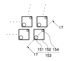
次に、与えられたドット配置DにおいてランダムにドットONの位置P1 とドットOFFの位置P2 を選択する(ステップS118)。図2にその概念図を示す。図2は、画像平面におけるドットの形成が可能な画素点(画素位置)を正方格子状の矩形の枡目セル(メッシュ)で表した模式図である。同図中、黒塗りで表示された画素位置は、ドットONの位置(ドットが配置された位置)を表し、図中白抜きで表示された画素位置は、ドットOFFの位置(ドットが配置されていない位置)を表す。なお、実際の装置では、画素位置(i,j)を示す正方形領域よりも大きな略円形に近いドットが形成され、ベタ画像を印字した場合にドット間に隙間が発生しないようになっている。 Next, in the given dot arrangement D, a dot ON position P1 and a dot OFF position P2 are selected at random (step S118). The conceptual diagram is shown in FIG. FIG. 2 is a schematic diagram in which pixel points (pixel positions) at which dots can be formed on the image plane are represented by square grid-like rectangular grid cells (mesh). In the figure, the pixel position displayed in black represents the dot ON position (position where the dot is arranged), and the pixel position displayed in white in the figure is the dot OFF position (dot is arranged). Position). In an actual apparatus, dots that are close to a substantially circular shape that is larger than the square area indicating the pixel position (i, j) are formed, and no gap is generated between dots when a solid image is printed.
図2のように、I画素×J画素(ただし、I,Jは任意の正の整数)の画素領域内にM個のドットを配置した状態(あるドット配置Dの状態)で、ランダムにドットONの位置P1 とドットOFFの位置P2 をそれぞれ1つずつ選択する(図1のステップS118)。 As shown in FIG. 2, in a state where M dots are arranged in a pixel area of I pixels × J pixels (where I and J are arbitrary positive integers) (state of a certain dot arrangement D), random dots One ON position P1 and one dot OFF position P2 are selected (step S118 in FIG. 1).
そして、これら選択したドットONの位置P1 をドットOFFに、ドットOFFの位置P2 をドットONに変更したドット配置Dx を求め、この変更した結果のドット配置Dx についての評価値Ex (ただし、Ex =Est(Dx ))を計算する(ステップS120)。 Then, a dot arrangement Dx in which the selected dot ON position P1 is changed to dot OFF and the dot OFF position P2 is changed to dot ON is obtained, and the evaluation value Ex (ex = Est (Dx)) is calculated (step S120).
次いで、ドット配置Dの評価値Eと、変更後のドット配置Dx の評価値Ex との差(評価値ΔE)を計算する(ステップS122)。すなわち、評価値差ΔE=Ex −Eを計算する。 Next, a difference (evaluation value ΔE) between the evaluation value E of the dot arrangement D and the evaluation value Ex of the changed dot arrangement Dx is calculated (step S122). That is, the evaluation value difference ΔE = Ex−E is calculated.
こうして求めた評価値差ΔEからポテンシャルPを計算する(ステップS124)。ポテンシャルPは、評価値差ΔEに応じて定義され、ΔE<0の場合はP=1、ΔE≧0の場合はP=exp(−ΔE/T)の式で定義される。このポテンシャルPの定義は、次ステップS126における乱数と、ステップS128における不等式の判定との関係から定められている。 The potential P is calculated from the evaluation value difference ΔE thus obtained (step S124). The potential P is defined according to the evaluation value difference ΔE. When ΔE <0, P = 1, and when ΔE ≧ 0, P = exp (−ΔE / T). The definition of the potential P is determined from the relationship between the random number in the next step S126 and the determination of the inequality in step S128.
ステップS126では、0以上1以下の範囲で乱数Ranを発生させている。続くステップS128では乱数RanとポテンシャルPの大小関係を判断し、Ran≦Pの不等式を満たすか否かが判定される。 In step S126, a random number Ran is generated in the range of 0 to 1. In the following step S128, the magnitude relationship between the random number Ran and the potential P is determined, and it is determined whether or not the inequality Ran ≦ P is satisfied.
乱数Ranは0から1の範囲の数なので、ポテンシャルP=1であれば、ステップS128の不等式判定で必ずYESとなる。つまり、評価値差ΔEが負となる方向では、必ずYESが選択され、ステップS130に進むことを意味する。 Since the random number Ran is a number in the range of 0 to 1, if the potential P = 1, the inequality determination in step S128 is always YES. That is, in the direction in which the evaluation value difference ΔE is negative, it means that YES is always selected and the process proceeds to step S130.
その一方、評価値差ΔEが0以上のときは、ポテンシャルPは、P=exp(−ΔE/T)で定義されるため、このときPは、0<P≦1の範囲の値をとることになる。温度Tが高い時にはPの値は「1」に近い値となり、温度Tが低くなるにつれてPの値は次第に「0」に近い値となる。 On the other hand, when the evaluation value difference ΔE is greater than or equal to 0, the potential P is defined by P = exp (−ΔE / T). At this time, P takes a value in the range of 0 <P ≦ 1. become. When the temperature T is high, the value of P becomes close to “1”, and as the temperature T becomes low, the value of P gradually becomes close to “0”.
乱数Ranは確率的に0.5付近の値を取り易いため、温度Tが高いほど高い確率でステップS128の不等式判定がYESになる。また、温度Tが低くなるほどステップS128の不等式判定がNOになる確率が高くなる。 Since the random number Ran is probable to take a value near 0.5 in terms of probability, the higher the temperature T, the higher the inequality determination in step S128 becomes YES. In addition, the lower the temperature T, the higher the probability that the inequality determination in step S128 is NO.
ステップS128でYESの場合は、ステップS130に進み、ドット配置DをDx に変更するとともに、評価値EをEx に変更する。これは、位置P1 とP2 のON/OFFを入れ換えたドット配置Dx を採用して、これをドット配置Dと読み替え、評価値Ex を評価値Eに読み替えることを意味する。 If YES in step S128, the process proceeds to step S130, where the dot arrangement D is changed to Dx, and the evaluation value E is changed to Ex. This means that the dot arrangement Dx in which the positions P1 and P2 are switched ON / OFF is adopted, this is read as the dot arrangement D, and the evaluation value Ex is read as the evaluation value E.
ステップS130の後は、ステップS132に進み、カウンタCntの値を「+1 」カウントアップする。また、ステップS128でNOの場合は、評価値Ex 、ドット配置Dx を破棄して、ステップS132に進む。 After step S130, the process proceeds to step S132, and the value of the counter Cnt is incremented by “+1”. If NO in step S128, the evaluation value Ex and the dot arrangement Dx are discarded, and the process proceeds to step S132.
次いで、カウンタCntの計数値が所定の繰り返し規定値Cnte を超えたか否かを判定する(ステップS134)。この繰り返し規定値Cnte は、温度Tの低減演算を毎ループ実行すると計算が複雑になることに配慮して、所定の繰り返し回数(Cnte 回)だけ同じ温度で演算を繰り返し、Cnte 回カウントを回したら一定量の温度を下げるという処理を行うために設定されている。 Next, it is determined whether or not the count value of the counter Cnt has exceeded a predetermined repeated specified value Cnte (step S134). This repetitive specified value Cnte is calculated by repeating the calculation at the same temperature for a predetermined number of repetitions (Cnte times) in consideration of the fact that the calculation becomes complicated when the temperature T reduction calculation is executed every loop. It is set to perform a process of lowering a certain amount of temperature.
すなわち、ステップS134でNOならば、温度Tが最終温度Te よりも低くなったか否かを判定し( ステップS138)、NOならばステップS118に戻って、新しいP1 ,P2 を選び、上記の処理を繰り返す。 That is, if NO in step S134, it is determined whether or not the temperature T has become lower than the final temperature Te (step S138). If NO, the process returns to step S118 to select new P1 and P2, and perform the above processing. repeat.
その一方、ステップS134でカウンタCntの計数値が所定の繰り返し規定値Cnte を超えるとステップS136に進み、カウンタCntを初期化(Cnt=0)するとともに、現在の温度Tに所定の低減率k(ただし、kは1より小さい正の数)を乗じて、温度Tを「T=kT」に更新する(ステップS136)。ステップS136の後は、ステップS138に進み、最終温度Te との比較判定を行う。ステップS138でNOならば、ステップS118に戻る。 On the other hand, when the count value of the counter Cnt exceeds the predetermined prescribed repeat value Cnte in step S134, the process proceeds to step S136, the counter Cnt is initialized (Cnt = 0), and the current temperature T is increased to a predetermined reduction rate k ( However, k is multiplied by a positive number smaller than 1 to update the temperature T to “T = kT” (step S136). After step S136, the process proceeds to step S138, and a comparison with the final temperature Te is performed. If NO in step S138, the process returns to step S118.
ステップS118〜S138の処理を繰り返し、ステップS138で温度Tが最終温度Te よりも低くなったら、処理を終了する。こうして、評価値Eが低くなったドット配置を得ることができる。 The processes in steps S118 to S138 are repeated. When the temperature T becomes lower than the final temperature Te in step S138, the process ends. In this way, a dot arrangement with a low evaluation value E can be obtained.
次に、評価値Eの計算例について説明する。 Next, a calculation example of the evaluation value E will be described.
ドット配置Dは、図2で説明したように、I×Jの画素領域におけるドットの2次元配置パターンであるとし、これをドット配置D(i,j)(0≦i,i<I,0≦j,j<J:ただし、ここでは、フルライン型の記録ヘッドによるシングルパス印字の主走査方向を変数iで表し、副走査方向を変数jで表す。)と表記する。このドット配置D(i,j)に対する評価値Eの計算方法の一例として、ドット評価関数EDot を以下のように定義する。 As described with reference to FIG. 2, the dot arrangement D is a two-dimensional arrangement pattern of dots in the I × J pixel region, and this is the dot arrangement D (i, j) (0 ≦ i, i <I, 0 ≦ j, j <J: Here, the main scanning direction of single-pass printing by a full-line type recording head is represented by a variable i, and the sub-scanning direction is represented by a variable j). As an example of a method for calculating the evaluation value E for the dot arrangement D (i, j), a dot evaluation function EDot is defined as follows.
ドット評価関数EDot は、粒状性評価関数と異方性評価関数の線形結合とし、次式(式A)によって表される。 The dot evaluation function EDot is a linear combination of the granularity evaluation function and the anisotropy evaluation function, and is expressed by the following equation (Equation A).
EDot(D) =wg ×粒状性評価関数(D)+wa ×異方性評価関数(D)…(式A)
ただし、wg ,wa は重み係数である
粒状性評価関数及び異方性評価関数としては、Robert,Ulichneyが提唱したドット明度分布の極座標パワースペクトラムの平均指標(Radially Averaged Power Spectrum; R.A.P.S)と分散指標(Anisotropy)」を用いることができる。
EDot (D) = wg × granularity evaluation function (D) + wa × anisotropic evaluation function (D) (formula A)
However, wg and wa are weighting factors. Graininess evaluation function and anisotropy evaluation function are the average index (Radially Averaged Power Spectrum; RAPS) and dispersion index of dot brightness distribution proposed by Robert and Ulichney. (Anisotropy) "can be used.
デジタルハーフトーニングの結果としてドットパターンが得られ、このドットパターン(ドット配置)の評価法としては、Robert,Ulichneyが提唱した方法が一般的に知られている(『Digital Halftoning』; The MIT Press出版)。 A dot pattern is obtained as a result of digital halftoning, and a method proposed by Robert and Ulichney is generally known as a method for evaluating this dot pattern (dot arrangement) ("Digital Halftoning"; published by The MIT Press) ).
すなわち、ドット配置によって得られる網点画像の2次元パワースペクトラムを極座標に変換して、図3のように、極座標の半径に対応する空間周波数fr について全角度のスペクトラムの平均と分散に相当する指標を用いる。 That is, the two-dimensional power spectrum of the halftone image obtained by dot arrangement is converted into polar coordinates, and an index corresponding to the average and variance of the spectrum at all angles with respect to the spatial frequency fr corresponding to the radius of the polar coordinates as shown in FIG. Is used.
極座標パワースペクトラムの平均指標を「R.A.P.S 」とよび、次式で表す。 The average index of the polar coordinate power spectrum is called “R.A.P.S” and is expressed by the following equation.

図4には、ある好ましい条件で計算されたR.A.P.S の例が示されている。図4においてσg は、次式で表される。 FIG. 4 shows an example of RAPS calculated under certain favorable conditions. In FIG. 4, σ g is expressed by the following equation.
![]()
![]()
図4に示したグラフでは視覚特性は考慮されていなが、これに、図5のような、公知の視覚特性(VTF)を考慮すると(掛け合わせると)、全体にエネルギーが低く抑えられたものになる。なお、R.A.P.S やAnisotropyを計算する際のVTFには、Dooly&Shawが提唱するものに限定されず、公知のものを使うことができる。 In the graph shown in FIG. 4, the visual characteristic is not taken into consideration, but when the known visual characteristic (VTF) as shown in FIG. 5 is taken into consideration (when multiplied), the energy is kept low overall. become. The VTF for calculating R.A.P.S and Anisotropy is not limited to the one proposed by Dooly & Shaw, and a known one can be used.
また、図6には、ある好ましい条件で計算されたAnisotropy の一例が示されている。Robert Ulichney によると、Anisotropyが−10デシベル〔dB〕以下であれば、ドットの異方性は目立たないとされている。 FIG. 6 shows an example of Anisotropy calculated under certain preferable conditions. According to Robert Ulichney, the anisotropy of dots is inconspicuous if Anisotropy is -10 dB [dB] or less.
本実施形態では、上述したR.A.P.S を粒状性評価関数(D)に利用し、Anisotropyを異方性評価関数(D)に利用してドット評価関数EDot(D) が上述の(式A)で定義される。 In this embodiment, the dot evaluation function EDot (D) is defined by the above (formula A) using the above-described RAPS as the graininess evaluation function (D) and the Anisotropy as the anisotropy evaluation function (D). Is done.
このドット評価関数EDot(D) は、次のように使用される。まず、ノズル不吐出がない状態でのEDot を計算し、その計算結果をEDotAとする。次に、i番目の画素位置にドットを形成するノズル(以下、i番目のノズルという。)が不吐出の状態でのEDot を計算し、その計算結果をEDotiとする。i番目のノズルが不吐出になると、当該ノズルでドットを形成することができないため、ドット配置Dのうちiの位置についてドットOFFにしてEDot を計算する。なお、EDot は値が小さいほど評価が良いと仮定する。 This dot evaluation function EDot (D) is used as follows. First, EDot in a state where there is no nozzle non-ejection is calculated, and the calculation result is taken as EDotA. Next, EDot is calculated when a nozzle that forms a dot at the i-th pixel position (hereinafter referred to as the i-th nozzle) is not ejected, and the calculation result is EDoti. When the i-th nozzle is not ejected, dots cannot be formed by the nozzle, and therefore, the dot is turned off at the position i in the dot arrangement D and EDot is calculated. It is assumed that EDot is evaluated better as the value is smaller.
続いて、ノズル不吐出による変動評価値EDelta を計算する。この変動評価値EDelta は、ノズル不吐出によるドット評価関数EDot の悪化を計算している。変動評価値EDelta の計算例を以下に示す。 Subsequently, a fluctuation evaluation value EDelta due to nozzle non-ejection is calculated. This fluctuation evaluation value EDelta calculates the deterioration of the dot evaluation function EDot due to nozzle non-ejection. A calculation example of the fluctuation evaluation value EDelta is shown below.
(計算例1):EDelta =Σ{EDoti−EDotA} (0≦i,i<I)
(計算例2):EDelta =MAX(EDoti−EDotA) (0≦i,i<I)
上記の(計算例1)は、何も欠陥のない状態(EDotA)に対して、全てのノズルについて順次1ノズルずつ不吐出だったと仮定してEDotiを計算し、EDotAからの差分を計算することで、不吐出によってEDot が悪くなった量を求め、その悪化量を全ノズルについて積算している。つまり、(計算例1)は、ノズル不吐出によるドット評価関数EDot の悪化の平均値に相当する値を計算していることになる。
(Calculation Example 1): EDelta = Σ {EDoti−EDotA} (0 ≦ i, i <I)
(Calculation Example 2): EDelta = MAX (EDoti−EDotA) (0 ≦ i, i <I)
In the above (Calculation Example 1), EDoti is calculated on the assumption that there was no ejection one by one for all nozzles in the state without any defects (EDotA), and the difference from EDotA is calculated. Thus, the amount by which EDot deteriorates due to non-ejection is obtained, and the amount of deterioration is integrated for all nozzles. That is, (Calculation Example 1) calculates a value corresponding to the average value of the deterioration of the dot evaluation function EDot due to nozzle non-ejection.
一方、(計算例2)は、何も欠陥のない状態(EDotA)に対して、不吐出によるドット評価関数EDot が最も悪くなった場合の値(最悪値)に相当する値を計算していることになる。 On the other hand, (Calculation Example 2) calculates a value corresponding to a value (worst value) when the dot evaluation function EDot due to non-ejection becomes worst with respect to a state without any defects (EDotA). It will be.
上記例示した(計算例1)又は(計算例2)の何れかの定義に従って計算される変動評価値EDelta は、不吐出による変動が悪くなったことを示す指標である。求めたいものはノズルの不吐出が発生した場合に、そのドット抜けによるムラが目立たないものであるから、上記の変動評価値EDelta が最も小さいもの(不吐出による変動が最も少ないドット配置)が望ましいドット配置である。 The fluctuation evaluation value EDelta calculated according to the definition of either (Calculation Example 1) or (Calculation Example 2) exemplified above is an index indicating that fluctuation due to non-ejection has deteriorated. What is desired is that the nonuniformity due to missing dots is inconspicuous when nozzle non-ejection occurs. Therefore, it is desirable that the above-mentioned fluctuation evaluation value EDelta is the smallest (dot arrangement with the smallest fluctuation due to non-ejection). Dot arrangement.
以上から、最終的に図1で説明した評価値Eは、次式(式B)に示すように、変動評価値EDelta と、不吐出の無い状態でのドット評価値EDotAの線形結合で定義される。 From the above, the evaluation value E finally explained with reference to FIG. 1 is defined by a linear combination of the fluctuation evaluation value EDelta and the dot evaluation value EDotA in the absence of non-ejection, as shown in the following equation (Formula B). The
E=Est(D)=wdelta ×EDelta +wdot ×EDotA …(式B)
ただし、wdelta ,wdot は重み係数である。
E = Est (D) = wdelta × EDelta + wdot × EDotA (Formula B)
Here, wdelta and wdot are weighting factors.
上記の(式B)のように、評価値EをEDelta とEDotAの線形結合で定義することにより、ドット抜けがある場合にはその変動が少なく、更に、ドット抜けが無い場合にも粒状性が良く、且つ異方性の少ない良好なドット配置が求められる。 By defining the evaluation value E as a linear combination of EDelta and EDotA as in (Equation B) above, there is little fluctuation when there is a missing dot, and there is no graininess even when there is no missing dot. A good dot arrangement with good anisotropy is required.
上述した演算フローを利用することにより、ドットがM個のときの良好なドット配置(ドット抜けによるムラが目立ちにくく、且つドット抜けが無い場合にも良好な画像品質が得られるドット配置)を計算することができる。 By using the calculation flow described above, it is possible to calculate a good dot arrangement when there are M dots (dot arrangement that makes it difficult to notice unevenness due to missing dots and provides good image quality even when there are no missing dots). can do.
上述の方法によって求めたM個の最適なドット配置を基にして、ドットの数を増やした場合のドット配置、或いはドットの数を減らした場合のドット配置を求める方法を説明する。なお、本実施形態において最終的に目指すものは、最小ドット数から最大ドット数までの各ドット数についての最適なドット配置を決定し、これらドット配置から閾値マトリクスを決定することである。 A method for obtaining the dot arrangement when the number of dots is increased or the dot arrangement when the number of dots is reduced based on the M optimum dot arrangements obtained by the above-described method will be described. In the present embodiment, the final goal is to determine the optimum dot arrangement for each number of dots from the minimum number of dots to the maximum number of dots, and to determine the threshold matrix from these dot arrangements.
[ 手順1] まず、図1で説明したSAの基本フローチャートを使って、適当なドット数Mでの最適なドット配置DP(M) を決定する。 [Procedure 1] First, the optimal dot arrangement DP (M) with an appropriate number of dots M is determined using the SA basic flowchart described in FIG.
[ 手順2] 次に、このドット配置DP(M) に対して適当なドット数Qだけ更にドットONしたドット配置DP(M+Q)を、図7に示すフローチャートを使って求める(図7については後述する)。つまり、既に確定しているM個のドット配置を変えずに、それ以外の位置にQ個のドットを追加して計算を行う。 [Procedure 2] Next, a dot arrangement DP (M + Q) in which dots are further turned ON by an appropriate number Q of dots is obtained for this dot arrangement DP (M) using the flowchart shown in FIG. 7 (FIG. 7 will be described later). To do). That is, the calculation is performed by adding Q dots at other positions without changing the M dot arrangements that have already been determined.
[ 手順3] また、同様の考え方によって、ドット配置DP(M) から適当なドット数RだけドットOFFしたドット配置DP(M−R)を求めることができる(図8については後述する)。 [Procedure 3] Also, based on the same concept, it is possible to obtain a dot arrangement DP (M-R) in which dots are OFF by an appropriate number of dots R from the dot arrangement DP (M) (FIG. 8 will be described later).
上記の手順2,3と同様の計算を繰り返し行うことによって、図9に示すように、ドットONの数(ドット数)が異なるドット配置を決定することができる。図9は、ドット配置DP(M) からスタートして、ドット数を増加又は減少させながら順次、図面の下方向に向かってドット配置を決定して行く様子を模式的に示した概念図である。すなわち、ドット配置DP(M) からドット配置DP(M+Q),DP(M−R)が求められ、更に、DP(M+Q)からドット数をQ1 個減らしたDP(M+Q−Q1 )と、DP(M+Q)にドット数をQ2 個追加したDP(M+Q+Q2 )とが求められる。また、DP(M−R)からドット数をR1 個減らしたDP(M−R−R1 )と、DP(M−R)にドット数をR2 個追加したDP(M−R+R2 )とが求められる。 By repeatedly performing the same calculation as in steps 2 and 3, dot arrangements having different numbers of dot ONs (dot numbers) can be determined as shown in FIG. FIG. 9 is a conceptual diagram schematically showing how the dot arrangement is determined in the downward direction of the drawing starting from the dot arrangement DP (M) and sequentially increasing or decreasing the number of dots. . That is, the dot arrangement DP (M + Q) and DP (M−R) are obtained from the dot arrangement DP (M), and DP (M + Q−Q1) and DP (M) are obtained by reducing the number of dots by Q1 from DP (M + Q). DP (M + Q + Q2) is obtained by adding Q2 dots to M + Q). Further, DP (MR-R1) obtained by reducing the number of dots by R1 from DP (MR) and DP (MR-R2) obtained by adding R2 dots to DP (MR) are obtained. .
ただし、例えば、DP ( M−R+R2 ) を決める場合、R2 個のドットONは、DP(M−R)においてドットOFF且つDP(M+Q)においてドットONであるドット位置に制約する必要がある。同様に、DP ( M+Q−Q1 )を決める場合、Q1 個のドットOFFは、DP(M−R)においてドットOFF且つDP(M+Q)においてドットONであるドット位置に制約する必要がある。 However, for example, when determining DP (M-R + R2), it is necessary to constrain R2 dots ON to dot positions that are dot OFF in DP (MR) and dot ON in DP (M + Q). Similarly, when determining DP (M + Q-Q1), it is necessary to constrain Q1 dots OFF to dot positions that are dot OFF in DP (MR) and dot ON in DP (M + Q).
このように、これからドット配置を決めようとするあるドット数(X個)について上記のような、制約を与えるドット配置について以下のように定義する。 As described above, the dot arrangement that gives the constraints as described above is defined as follows for a certain number of dots (X) for which the dot arrangement is to be determined.
すなわち、既に決定されたあるドット配置に対してドットONの位置を追加する(ドット数を増加させる)方向のドット数のドット配置を求めようとする場合には、当該求めようとするドット数X個から見てドット数が減少する方向でドット数が最も近く、且つ既にドット配置が決定されているものを「Ds 」(初期配置)とする。また、ドット数X個から見てドット数が増加する方向でドット数が最も近く、且つ既にドット配置が決定されているものを「Dr 」(参照ドット配置)とする。 That is, when trying to obtain the dot arrangement of the number of dots in the direction of adding the dot ON position (increasing the number of dots) to a certain already determined dot arrangement, the number of dots X to be obtained X “Ds” (initial arrangement) is the one in which the number of dots is the closest in the direction of decreasing the number of dots as viewed from the individual and the dot arrangement has already been determined. Further, “Dr” (reference dot arrangement) is the one in which the number of dots is closest in the direction in which the number of dots increases as viewed from the number of dots X and the dot arrangement has already been determined.
つまり、Dr のドットON位置の集合とDs のドットON位置の集合の差集合の中から、(X−Ds )個のドットのON位置(Ds からの追加分のドットの位置) が決定される。このような制約の下で最適なドット配置を決定するフローチャートが図7に示されている。 That is, the ON position of (X−Ds) dots (the position of the additional dots from Ds) is determined from the difference set between the set of the dot ON positions of Dr and the set of the dot ON positions of Ds. . FIG. 7 shows a flowchart for determining the optimum dot arrangement under such constraints.
或いはまた、既に決定されたあるドット配置に対してドットONの位置を減らす(ドット数を減少させる)方向のドット数のドット配置を求めようとする場合には、当該求めようとするドット数X個から見てドット数が増加する方向でドット数が最も近く、且つ既にドット配置が決定されているものを「Ds 」(初期配置)とする。また、ドット数X個から見てドット数が減少する方向でドット数が最も近く、且つ既にドット配置が決定されているものを「Dr 」(参照ドット配置)とする。 Alternatively, when the dot arrangement of the number of dots in the direction of decreasing the dot ON position (decreasing the number of dots) with respect to a certain dot arrangement already determined is to be obtained, the number of dots X to be obtained X “Ds” (initial arrangement) is the one in which the number of dots is closest in the direction in which the number of dots increases as viewed from the individual and the dot arrangement has already been determined. Further, “Dr” (reference dot arrangement) is the one in which the number of dots is closest in the direction in which the number of dots decreases as viewed from the number of dots X and the dot arrangement has already been determined.
つまり、Ds のドットON位置の集合とDr のドットON位置の集合の差集合の中から、(Ds −X) 個のドットのOFF位置(Ds からの減少分のドットの位置)が決定される(実際の演算では結果的に、Dr に対して追加されるドットONの位置が決定される) 。このような制約の下で最適なドット配置を決定するフローチャートが図8に示されている。 That is, the OFF position of (Ds−X) dots (the position of the dot corresponding to the decrease from Ds) is determined from the difference set between the set of Ds dot ON positions and the set of Dr dot ON positions. (The actual calculation results in the determination of the position of the dot ON added to Dr.) FIG. 8 shows a flowchart for determining the optimum dot arrangement under such restrictions.
図9に示した演算結果からから更に、上記同様の処理を進めて、図10のように、ドット配置DP ( M−R+R2 −R3 ) ,DP ( M−R+R2 +R4) ,DP ( M+Q−Q1 −Q3 ) ,DP ( M+Q−Q1 +Q4 ) が求められる。例えば、DP (M−R+R2 )からドット数をR4 個増やしてDP ( M−R+R2 +R4)を求める際には、DP ( M−R+R2 ) が初期配置Ds となり、DP ( M+Q−Q1 )が参照ドット配置Dr となる。また、DP ( M+Q−Q1 )からドット数をQ3 個減らしてDP ( M+Q−Q1 −Q3 ) を求める場合には、DP ( M+Q−Q1 )が初期配置Ds となり、DP ( M−R+R2 ) が参照ドット配置Dr となる。 From the calculation results shown in FIG. 9, the same processing as described above is further performed, and as shown in FIG. 10, dot arrangement DP (MR-R2-R3), DP (MR-R2 + R4), DP (M + Q-Q1- Q3) and DP (M + Q-Q1 + Q4) are obtained. For example, when DP (M-R + R2 + R4) is obtained by increasing the number of dots by R4 from DP (M-R + R2), DP (M-R + R2) becomes the initial arrangement Ds, and DP (M + Q-Q1) is the reference dot. Arrangement Dr. When DP (M + Q-Q1-Q3) is obtained by reducing the number of dots by Q3 from DP (M + Q-Q1), DP (M + Q-Q1) is the initial arrangement Ds, and DP (M-R + R2) is referred to. The dot arrangement Dr is obtained.
こうして、上記の処理を繰り返すことにより、ドット数の大きいドット配置がそれよりもドット数の小さいドット配置を常に包含する関係を維持して、各ドット数のドット配置が決定される。 In this way, by repeating the above processing, the dot arrangement of each dot number is determined while maintaining the relationship in which the dot arrangement having a large number of dots always includes the dot arrangement having a smaller number of dots.
最終的には、最小ドット数(1個)から最大ドット数(I×J個)までドットONのドット数が1つずつ増加したドット数ごとのドット配置を決定できる。つまり、上記の[ 手順2] 及び[ 手順3] の処理では、元になったドット配置を基準にして、当該ドット配置に対してドットをON若しくはOFFにする画素位置を決定するため、ドットONのドット数が1だけ違うドット配置を比較すると、ドットONの位置が1つだけ異なることが保証される。 Finally, it is possible to determine the dot arrangement for each number of dots in which the number of dots ON is increased by one from the minimum number of dots (1) to the maximum number of dots (I × J). In other words, in the processes of [Procedure 2] and [Procedure 3], the dot ON is determined in order to determine the pixel position where the dot is turned ON or OFF with respect to the original dot arrangement. Comparing dot arrangements in which the number of dots is different by 1 ensures that the dot ON position is different by one.
このように、最小ドット数(1個)から最大ドット数(I×J個)までドットONのドット数が1つずつ増加したドット数ごとのドット配置に基づき、新規にドットONになるドット位置に対して閾値を順次(1ずつ増加させて)割り当てることによって、閾値マトリクスを作成することができる。なお、求めようとする閾値マトリクスの画素サイズによって、画素数I,Jを設定すればよい。 Thus, based on the dot arrangement for each number of dots in which the number of dots ON is increased by one from the minimum number of dots (1) to the maximum number of dots (I × J), the dot position where the dot is newly turned on By sequentially assigning thresholds to (incremented by 1), a threshold matrix can be created. The number of pixels I and J may be set according to the pixel size of the threshold matrix to be obtained.
次に、図7のフローチャートを説明する。図7は、基準となるドット配置からドットを増やす場合のドット配置の決定手順を示したフローチャートである。同図中図のフローチャートと同一又は類似する工程には同一の符号を付し、その説明は省略する。 Next, the flowchart of FIG. 7 will be described. FIG. 7 is a flowchart showing a procedure for determining the dot arrangement when the number of dots is increased from the reference dot arrangement. Steps that are the same as or similar to those in the flowchart in the figure are given the same reference numerals, and descriptions thereof are omitted.
図7に示したフローチャートは、図1のフローチャートにおけるステップS110とステップS118とがそれぞれ、図7のようにステップS110A、ステップS118Aに置き換えられている。 In the flowchart shown in FIG. 7, step S110 and step S118 in the flowchart of FIG. 1 are respectively replaced with step S110A and step S118A as shown in FIG.
ステップS110Aでは、ドット配置Dの初期値(この場合、図9及び図10で説明した初期配置Ds )を設定するとともに、参照ドット配置Dr を設定する。そして、ドット配置Ds においてドットOFF且つ参照ドット配置Dr においてドットONの位置の中からN個のドットをドットONにする。 In step S110A, the initial value of the dot arrangement D (in this case, the initial arrangement Ds described with reference to FIGS. 9 and 10) is set, and the reference dot arrangement Dr is set. Then, N dots are turned ON from the dot OFF positions in the dot arrangement Ds and the dot ON positions in the reference dot arrangement Dr.
すなわち、「初期値Ds のドット数」と、「求めるドット数」(ドット配置を決定しようとしているドット数)、及び参照ドット配置Dr のドット数を比較すると、以下に示す関係、
(Ds のドット数)<(求めるドット数)<(Dr のドット数)…(関係式1)
を有しており、
(求めるドット数)=(Ds のドット数)+N …(関係式2)
である。
That is, when the “number of dots of the initial value Ds” is compared with the “number of dots to be obtained” (the number of dots about to determine the dot arrangement) and the number of dots of the reference dot arrangement Dr,
(Number of dots of Ds) <(Number of dots to be obtained) <(Number of dots of Dr) ... (Relational expression 1)
Have
(Number of dots to be obtained) = (Number of dots of Ds) + N (Relational formula 2)
It is.
図7のステップS118Aにおいて、P1 とP2 を選択する際には、ドット配置Ds でドットOFF且つ参照ドット配置Dr でドットONであるようなドット配置からランダムにドットONの位置P1 と、ランダムにドットOFFの位置P2 を選ぶ。以後の処理は図1で説明したとおりである。 When P1 and P2 are selected in step S118A in FIG. 7, the dot placement Ds is dot OFF and the reference dot placement Dr is dot ON. Select the OFF position P2. The subsequent processing is as described in FIG.
このように、ドットONの可能性のあるドット位置に制約を設けて演算を行うことにより、初期配置Ds と参照ドット配置Dr の両配置に対してドット数の増減によるドット配置の包含関係を維持するようなドット配置を決定することができる。 In this way, by performing the calculation with restrictions on the dot positions where there is a possibility of dot ON, the inclusive relationship of dot arrangements by increasing or decreasing the number of dots is maintained for both the initial arrangement Ds and the reference dot arrangement Dr. The dot arrangement can be determined.
図8は、基準となるドット配置からドットを減らす場合のドット配置の決定手順を示したフローチャートである。同図中図1のフローチャートと同一又は類似する工程には同一の符号を付し、その説明は省略する。 FIG. 8 is a flowchart showing a procedure for determining the dot arrangement when the number of dots is reduced from the reference dot arrangement. In the figure, the same or similar steps as those in the flowchart of FIG. 1 are denoted by the same reference numerals, and the description thereof is omitted.
図8に示したフローチャートは、図1のフローチャートにおけるステップS110とステップS118とがそれぞれ、図8のようにステップS110B、ステップS118Bに置き換えられている。 In the flowchart shown in FIG. 8, step S110 and step S118 in the flowchart of FIG. 1 are replaced with step S110B and step S118B, respectively, as shown in FIG.
ステップS110Bでは、ドット配置Dの初期値(この場合、図9及び図10で説明した初期配置Ds )を設定するとともに、参照ドット配置Dr を設定する。そして、ドット配置Ds においてドットON且つ参照ドット配置Dr においてドットOFFの位置の中からN個のドットをドットOFFにする。 In step S110B, the initial value of the dot arrangement D (in this case, the initial arrangement Ds described with reference to FIGS. 9 and 10) is set, and the reference dot arrangement Dr is set. Then, N dots are turned off from the positions of dot ON in the dot arrangement Ds and dot OFF in the reference dot arrangement Dr.
すなわち、「初期値Ds のドット数」と、「求めるドット数」(ドット配置を決定しようとしているドット数)、及び参照ドット配置Dr のドット数を比較すると、以下に示す関係、
(Dr のドット数)<(求めるドット数)<(Ds のドット数)…(関係式3)
を有しており、
(求めるドット数)=(Ds のドット数)−N …(関係式2)
である。
That is, when the “number of dots of the initial value Ds” is compared with the “number of dots to be obtained” (the number of dots about to determine the dot arrangement) and the number of dots of the reference dot arrangement Dr,
(Number of dots of Dr) <(Number of dots to be obtained) <(Number of dots of Ds) (Relational expression 3)
Have
(Number of dots to be obtained) = (Number of dots of Ds) −N (Relational expression 2)
It is.
図8のステップS118Bにおいて、P1 とP2 を選択する際には、ドット配置Ds でドットON且つ参照ドット配置Dr でドットOFFであるようなドット配置からランダムにドットONの位置P1 と、ランダムにドットOFFの位置P2 を選ぶ。以後の処理は図1で説明したとおりである。 When P1 and P2 are selected in step S118B of FIG. 8, the dot ON position P1 is randomly changed from the dot arrangement in which the dot arrangement Ds is dot ON and the reference dot arrangement Dr is dot OFF. Select the OFF position P2. The subsequent processing is as described in FIG.
このように、ドットOFFの可能性のあるドット位置に制約を設けて演算を行うことにより、初期配置Ds と参照ドット配置Dr の両配置に対してドット数の増減によるドット配置の包含関係を維持するようなドット配置を決定することができる。 In this way, by performing the calculation with restrictions on the dot positions where there is a possibility of dot OFF, the inclusive relation of the dot arrangement by maintaining the dot number with respect to both the initial arrangement Ds and the reference dot arrangement Dr is maintained. The dot arrangement can be determined.
上述の手法によって、最終的に、ドットONのドット数が1つずつ増加したドット数ごとのドット配置が決定され、このドット数毎のドット配置から閾値マトリクスが作成される。 By the above-described method, finally, the dot arrangement for each dot number in which the number of dots ON increases by one is determined, and a threshold matrix is created from the dot arrangement for each dot number.
次に、閾値マトリクスを計算する手順について説明する。 Next, a procedure for calculating the threshold matrix will be described.
まず、閾値マトリックスを計算する際の順序(すなわち、ドット配置を決める計算を実行していくドット数の順番)を決定する方法について説明する。具体的には、計算を実行する順番にドット数を並べた数列(序列集合R)を作成することになる。 First, a method for determining the order for calculating the threshold matrix (that is, the order of the number of dots for performing the calculation for determining the dot arrangement) will be described. Specifically, a numerical sequence (ordered set R) in which the number of dots is arranged in the order in which the calculation is executed is created.
例えば、図10においてドット配置の計算(決定)順が、ドット数M→(M+Q)→(M−R)→(M+Q+Q2) →…であるとすると、序列集合Rは、このドット数を順番に並べた数列{M,M+Q,M−R,M+Q+Q2 ,…}で表される。 For example, if the dot arrangement calculation (determination) order in FIG. 10 is the number of dots M → (M + Q) → (MR) → (M + Q + Q2) →... It is represented by a sequence of numbers {M, M + Q, MR, M + Q + Q2,.
以下、図11を参照して、閾値マトリクスを決定する際の順序決定方法の例を説明する。順番の決定方針は、同図(a)に示したように、最もノズル不吐の影響が大きいドット数を一番最初とし、次に一定の自由度(ドット配置を決定する自由度)を確保したドット数だけドットを増加したドットを2番目とする。 Hereinafter, with reference to FIG. 11, an example of an order determination method when determining a threshold matrix will be described. As shown in Fig. 6A, the order determination policy is to ensure the first number of dots that has the greatest influence of nozzle ejection failure, and then to ensure a certain degree of freedom (the degree of freedom to determine the dot arrangement). The number of dots increased by the number of dots set is the second.
続いて、ドット数を増加させる方向で更に一定の自由度(ドット配置を決定する自由度)を確保したドット数だけドットを増やしたドット数を3番目にする(同(b))。 Subsequently, the number of dots increased by the number of dots for which a certain degree of freedom (the degree of freedom for determining the dot arrangement) is further secured in the direction of increasing the number of dots is set to the third position ((b)).
同様にして、ドット数を増加させる(同(c))。そして、ドット数が最大ドット数まで到達したら、今度は1番目の(最初の)ドット数に対してドット数を減少させる方向でドットを減らしていく。 Similarly, the number of dots is increased ((c)). When the number of dots reaches the maximum number of dots, this time, the number of dots is decreased in the direction of decreasing the number of dots with respect to the first (first) number of dots.
すなわち、同(d)に示すように、1番目のドット数に対して一定の自由度(ドット配置を決定する自由度)を確保したドット数だけドットを減少させたドット数を次(ここでは「5番目」)にする。ドット数を減少させる方向で更に一定の自由度(ドット配置を決定する自由度)を確保したドット数だけドットを減少させたドット数を次にする(図(e))。同様にして、ドット数を減少させ、最小ドット数まで到達したら、今度は既に数列に出てきたドット数を仮にドット数が増加する方向に並べて、飛び飛びになっているドット数のおおよそ中間のドット数を次々に数列に加えて行く(同(f))。 That is, as shown in (d), the number of dots obtained by decreasing the number of dots by a number of dots that secures a certain degree of freedom (degree of freedom for determining the dot arrangement) with respect to the number of first dots (here, "5th"). Next, the number of dots in which the number of dots has been reduced by the number of dots for which a certain degree of freedom (the degree of freedom for determining the dot arrangement) has been secured in the direction of decreasing the number of dots is shown next (FIG. 5E). Similarly, when the number of dots is decreased and the minimum number of dots is reached, this time, the dots already appearing in the sequence are arranged in the direction in which the number of dots is increased, and approximately halfway between the skipped dots. Numbers are added to the sequence one after another ((f)).
この処理(同(f))を一巡した後に、もう一度、既に数列に出てきたドット数を仮にドット数が増加する方向に並べて、飛び飛びになっているドット数のおおよそ中間のドットを順次数列に加えていく。この作業を全て(最小ドット数から最大ドット数の間)選択するまで繰り返す。 After completing this process (same (f)), once again arrange the number of dots that have already appeared in the sequence in the direction in which the number of dots increases, and sequentially place dots that are approximately in the middle of the number of skipped dots in the sequence. I will add. This operation is repeated until all of the operations (between the minimum dot number and the maximum dot number) are selected.
こうして、得られた序列集合Rの順番に沿ってドット配置を計算していく。 Thus, the dot arrangement is calculated along the order of the obtained order set R.
図12は閾値マトリクスの計算手順を示したフローチャートである。図示のように、まず、閾値マトリクスを計算する際の順序決定方法(例えば、図11で例示した方法)を用いて、ドット数の順序集合Rを作成する(図12のステップS210)。 FIG. 12 is a flowchart showing a threshold matrix calculation procedure. As shown in the drawing, first, an order set R of the number of dots is created using the order determination method (for example, the method illustrated in FIG. 11) when calculating the threshold matrix (step S210 in FIG. 12).
次いで、順序集合Rの最初のドット数N0 に基づいて、SAの基本フローチャート(図1で説明済み)を使ってドット配置を決定する(図12のステップS212)。そして、この計算結果(つまり、決定されたドット数N0 のドット配置)をドット配列集合RDに格納する(ステップS214)。 Next, based on the first number of dots N0 of the ordered set R, the dot arrangement is determined using the SA basic flowchart (explained in FIG. 1) (step S212 in FIG. 12). Then, the calculation result (that is, the determined dot arrangement of the number of dots N0) is stored in the dot arrangement set RD (step S214).
こうして、ドット配置が決定されたら計算済みのドット数N0 を序列集合Rから削除する(ステップS216)。続いて、序列集合Rの中に次のドット数(ドット配置を求めるべきドット数)が残っているか否かを判断し(ステップS218)、残っていれば(YESならば)、序列集合Rの中から次のドット数Nx を取り出す(ステップS220)。 When the dot arrangement is determined in this way, the calculated dot number N0 is deleted from the ordered set R (step S216). Subsequently, it is determined whether or not the next number of dots (the number of dots for which the dot arrangement should be obtained) remains in the order set R (step S218). The next dot number Nx is extracted from the inside (step S220).
続いて、ドット配列集合RDの中からNx より小さい中で最も大きいドット数に対応するドット配置Du と、Nx より大きい中で最も小さいドット数に対応するドット配置Dv を選ぶ(ステップS222)。このとき、もし、Nx より小さいドット数が存在しない場合は、ドット数がゼロに対応するドット配置( 要するに全てドットOFF) をDu とする。また、もし、Nx より大きいドット数が存在しない場合は、全てのドットがONに相当するドット配置をDu とする。 Subsequently, the dot arrangement Du corresponding to the largest number of dots smaller than Nx and the dot arrangement Dv corresponding to the smallest number of dots larger than Nx are selected from the dot array set RD (step S222). At this time, if there is no dot number smaller than Nx, the dot arrangement corresponding to zero dot number (in short, all dots OFF) is set to Du. If there is no dot number larger than Nx, the dot arrangement corresponding to all dots being ON is set to Du.
次に、ステップS224に進む。ステップS224では、上記のステップS222で選択されたドット配置Du を「Ds 」、ドット配置Dv を「Dr 」とみなし、{Nx −(ドット配置Du のドット数)}をNとみなして、図7で説明したフローチャートを用いて、ドット数Nx のときのドット配置DNxを決定する。 Next, the process proceeds to step S224. In step S224, the dot arrangement Du selected in step S222 is regarded as “Ds”, the dot arrangement Dv is regarded as “Dr”, and {Nx− (the number of dots in the dot arrangement Du)} is regarded as N. FIG. The dot arrangement DNx when the number of dots is Nx is determined using the flowchart described in the above.
ただし、このステップS224は、次のような工程内容に置き換えることができる。すなわち、『ドット配置Du を「Dr 」、ドット配置Dv を「Ds 」とみなし、{(ドット配置Dv のドット数)−Nx }をNとみなして、図8で説明したフローチャートを用いて、ドット数Nx のときのドット配置DNxを決定する。』
そして、ステップS224の計算結果(つまり、決定されたドット数Nx のドット配置)をドット配列集合RDに格納し(ステップS226)、計算済みのドット数Nx を序列集合Rから削除する(ステップS228)。
However, this step S224 can be replaced with the following process contents. In other words, “dot arrangement Du is regarded as“ Dr ”, dot arrangement Dv is regarded as“ Ds ”, {(number of dots of dot arrangement Dv) −Nx} is regarded as N, and the dot described using the flowchart described in FIG. The dot arrangement DNx for the number Nx is determined. ]
Then, the calculation result of step S224 (that is, the dot arrangement of the determined number of dots Nx) is stored in the dot array set RD (step S226), and the calculated number of dots Nx is deleted from the order set R (step S228). .
ステップS228の後は、ステップS218に戻る。序列集合R内の全てのドット数についてドット配置が決定されるまで、ステップS218〜S228の工程が繰り返される。全てのドット数についてドット配置が決定され、序列集合Rから全ての要素(ドット数)が削除されると、ステップS218でNOとなり、処理を終了する。 After step S228, the process returns to step S218. Steps S218 to S228 are repeated until the dot arrangement is determined for all the numbers of dots in the ordered set R. When the dot arrangement is determined for all the dot numbers and all the elements (dot numbers) are deleted from the order set R, NO is determined in step S218, and the process ends.
こうして得られたドット配列集合RDの要素(ドット配置)をドット数順に並べ、新規にドットONになるドット位置に対して閾値を順次(1ずつ増加させて)割り当てることによって、閾値マトリクスを作成する。 The threshold matrix is created by arranging the elements (dot arrangement) of the dot array set RD thus obtained in the order of the number of dots and sequentially assigning the thresholds to the dot positions where the dots are newly turned on (incrementing by 1). .
上述したドット配置決定方法並びに閾値マトリクスの作成方法はコンピュータを用いて実現することができる。 The dot arrangement determination method and the threshold matrix creation method described above can be realized using a computer.
すなわち、上述したドット配置決定方法並びに閾値マトリクスの作成方法のアルゴリズムをコンピュータに実行させるプログラム(ドット配置決定処理プログラム、或いは、閾値マトリクス作成プログラム)を作成し、このプログラムによってコンピュータを動作させることにより、当該コンピュータをドット配置決定装置並びに閾値マトリクスの作成装置として機能させることができる。 That is, by creating a program (dot placement determination processing program or threshold matrix creation program) that causes a computer to execute the above-described dot placement determination method and threshold matrix creation method algorithm, and operating the computer with this program, The computer can function as a dot arrangement determination device and a threshold matrix creation device.
図13はコンピュータのシステム構成例を示すブロック図である。コンピュータ10は、本体12と、ディスプレイ(表示手段)14及びキーボードやマウスなど入力装置(各種の指示を入力するための入力手段)16から構成される。本体12内には中央演算処理装置(CPU)20、RAM22、ROM24、入力装置16からの信号入力を制御する入力制御部26、ディスプレイ14に対して表示用の信号を出力する表示制御部28、ハードディスク装置30、通信インターフェース32、及びメディアインターフェース34などを有し、これら各回路はバス36を介して相互に接続されている。
FIG. 13 is a block diagram illustrating a system configuration example of a computer. The
CPU20は、全体の制御装置及び演算装置(演算手段)として機能する。RAM22は、データの一時記憶領域やCPU20によるプログラム実行時の作業用領域として利用される。ROM24は、CPU20を動作させるブートプログラムや各種設定値・ネットワーク接続情報などを記憶する書き換え可能な不揮発性の記憶手段である。ハードディスク装置30には、オペレーティングシステム(OS)や各種のアプリケーションソフト(プログラム)やデータ等が格納される。
The
通信インターフェース32は、USBやLAN、Bluetooth など所定の通信方式に従って外部機器や通信ネットワークに接続するための手段である。メディアインターフェース34は、メモリカードや磁気ディスク、光磁気ディスク、光ディスクに代表される外部記憶装置38の読み書き制御を行う手段である。
The
本発明の実施形態に係るドット配置決定処理プログラムや閾値マトリクス作成プログラムは、ハードディスク装置30、或いは外部記憶装置38に格納されており、必要に応じて当該プログラムが読み出され、RAM22に展開されて実行される。或いは、通信インターフェース32を介して接続される不図示のネットワーク上に設置されたサーバによってプログラムが提供される態様も可能であるし、インターネット上のサーバによって本プログラムによる演算処理サービスを提供するという態様も考えられる。
The dot arrangement determination processing program and the threshold matrix creation program according to the embodiment of the present invention are stored in the
オペレータは、ディスプレイ14上に表示される不図示のアプリケーションウインドウを見ながら入力装置16を操作して所望のマトリクスサイズや各種初期値(計算を始めるドット数、初期温度など)の設定を入力することができるとともに、演算結果をディスプレイ14上で確認することができる。
The operator operates the
次に、上述した閾値マトリクス作成方法によって作成された閾値マトリクスが適用されるインクジェット記録装置の例を説明する。 Next, an example of an ink jet recording apparatus to which the threshold matrix created by the threshold matrix creating method described above is applied will be described.
〔インクジェット記録装置の全体構成〕
図14は、本発明に係る画像形成装置の一実施形態を示すインクジェット記録装置の全体構成図である。同図に示すように、このインクジェット記録装置110は、黒(K),シアン(C),マゼンタ(M),イエロー(Y)の各インクに対応して設けられた複数のインクジェット記録ヘッド(以下、ヘッドという。)112K,112C,112M,112Yを有する印字部112と、各ヘッド112K,112C,112M,112Yに供給するインクを貯蔵しておくインク貯蔵/装填部114と、記録媒体たる記録紙116を供給する給紙部118と、記録紙116のカールを除去するデカール処理部120と、前記印字部112のノズル面(インク吐出面)に対向して配置され、記録紙116の平面性を保持しながら記録紙116を搬送するベルト搬送部122と、印字部112による印字結果を読み取る印字検出部124と、記録済みの記録紙(プリント物)を外部に排紙する排紙部126とを備えている。
[Overall configuration of inkjet recording apparatus]
FIG. 14 is an overall configuration diagram of an ink jet recording apparatus showing an embodiment of an image forming apparatus according to the present invention. As shown in the figure, the ink
インク貯蔵/装填部114は、各ヘッド112K,112C,112M,112Yに対応する色のインクを貯蔵するインクタンクを有し、各タンクは所要の管路を介してヘッド112K,112C,112M,112Yと連通されている。また、インク貯蔵/装填部114は、インク残量が少なくなるとその旨を報知する報知手段(表示手段、警告音発生手段)を備えるとともに、色間の誤装填を防止するための機構を有している。
The ink storage / loading unit 114 includes ink tanks that store inks of colors corresponding to the
図14では、給紙部18の一例としてロール紙(連続用紙)のマガジンが示されているが、紙幅や紙質等が異なる複数のマガジンを併設してもよい。また、ロール紙のマガジンに代えて、又はこれと併用して、カット紙が積層装填されたカセットによって用紙を供給してもよい。 In FIG. 14, a magazine for rolled paper (continuous paper) is shown as an example of the paper supply unit 18, but a plurality of magazines having different paper widths, paper quality, and the like may be provided side by side. Further, instead of the roll paper magazine or in combination therewith, the paper may be supplied by a cassette in which cut papers are stacked and loaded.
複数種類の記録媒体(メディア)を利用可能な構成にした場合、メディアの種類情報を記録したバーコード或いは無線タグなどの情報記録体をマガジンに取り付け、その情報記録体の情報を所定の読取装置によって読み取ることで、使用される記録媒体の種類(メディア種)を自動的に判別し、メディア種に応じて適切なインク吐出を実現するようにインク吐出制御を行うことが好ましい。 When a plurality of types of recording media (media) can be used, an information recording body such as a barcode or a wireless tag that records media type information is attached to a magazine, and information on the information recording body is read by a predetermined reader. It is preferable to automatically determine the type of recording medium to be used (media type) and to perform ink ejection control so as to realize appropriate ink ejection according to the media type.
給紙部118から送り出される記録紙116はマガジンに装填されていたことによる巻きクセが残り、カールする。このカールを除去するために、デカール処理部120においてマガジンの巻きクセ方向と逆方向に加熱ドラム130で記録紙116に熱を与える。このとき、多少印字面が外側に弱いカールとなるように加熱温度を制御するとより好ましい。
The
ロール紙を使用する装置構成の場合、図14のように、裁断用のカッター(第1のカッター)128が設けられており、該カッター128によってロール紙は所望のサイズにカットされる。なお、カット紙を使用する場合には、カッター128は不要である。 In the case of an apparatus configuration using roll paper, a cutter (first cutter) 128 is provided as shown in FIG. 14, and the roll paper is cut to a desired size by the cutter 128. Note that the cutter 128 is not necessary when cut paper is used.
デカール処理後、カットされた記録紙116は、ベルト搬送部122へと送られる。ベルト搬送部122は、ローラ131、132間に無端状のベルト133が巻き掛けられた構造を有し、少なくとも印字部112のノズル面及び印字検出部124のセンサ面に対向する部分が水平面(フラット面)をなすように構成されている。
After the decurling process, the
ベルト133は、記録紙116の幅よりも広い幅寸法を有しており、ベルト面には多数の吸引穴(不図示)が形成されている。図14に示したとおり、ローラ131、132間に掛け渡されたベルト133の内側において印字部112のノズル面及び印字検出部124のセンサ面に対向する位置には吸着チャンバ134が設けられており、この吸着チャンバ134をファン135で吸引して負圧にすることによって記録紙116がベルト133上に吸着保持される。
The
ベルト133が巻かれているローラ131、132の少なくとも一方にモータ(図19中符号188)の動力が伝達されることにより、ベルト133は図1上の時計回り方向に駆動され、ベルト133上に保持された記録紙116は図14の左から右へと搬送される。
When the power of the motor (
縁無しプリント等を印字するとベルト133上にもインクが付着するので、ベルト133の外側の所定位置(印字領域以外の適当な位置)にベルト清掃部136が設けられている。ベルト清掃部136の構成について詳細は図示しないが、例えば、ブラシ・ロール、吸水ロール等をニップする方式、清浄エアーを吹き掛けるエアーブロー方式、或いはこれらの組合せなどがある。清掃用ロールをニップする方式の場合、ベルト線速度とローラ線速度を変えると清掃効果が大きい。
Since ink adheres to the
なお、ベルト搬送部122に代えて、ローラ・ニップ搬送機構を用いる態様も考えられるが、印字領域をローラ・ニップ搬送すると、印字直後に用紙の印字面をローラが接触するので画像が滲み易いという問題がある。したがって、本例のように、印字領域では画像面を接触させない吸着ベルト搬送が好ましい。 Although a mode using a roller / nip conveyance mechanism in place of the belt conveyance unit 122 is also conceivable, if the roller / nip conveyance is performed in the printing area, the image is likely to blur because the roller contacts the printing surface of the sheet immediately after printing. There's a problem. Therefore, as in this example, suction belt conveyance that does not bring the image surface into contact with each other in the print region is preferable.
ベルト搬送部122により形成される用紙搬送路上において印字部112の上流側には、加熱ファン140が設けられている。加熱ファン140は、印字前の記録紙116に加熱空気を吹き付け、記録紙116を加熱する。印字直前に記録紙116を加熱しておくことにより、インクが着弾後乾き易くなる。
A heating fan 140 is provided on the upstream side of the
印字部112の各ヘッド112K,112C,112M,112Yは、当該インクジェット記録装置110が対象とする記録紙116の最大紙幅に対応する長さを有し、そのノズル面には最大サイズの記録媒体の少なくとも一辺を超える長さ(描画可能範囲の全幅)にわたりインク吐出用のノズルが複数配列されたフルライン型のヘッドとなっている(図15参照)。
Each of the
ヘッド112K,112C,112M,112Yは、記録紙116の送り方向に沿って上流側から黒(K)、シアン(C)、マゼンタ(M)、イエロー(Y)の色順に配置され、それぞれのヘッド112K,112C,112M,112Yが記録紙116の搬送方向と略直交する方向に沿って延在するように固定設置される。
The
吸着ベルト搬送部122により記録紙116を搬送しつつ各ヘッド112K,112C,112M,112Yからそれぞれ異色のインクを吐出することにより記録紙116上にカラー画像を形成し得る。
A color image can be formed on the
このように、紙幅の全域をカバーするノズル列を有するフルライン型のヘッド112K,112C,112M,112Yを色別に設ける構成によれば、紙送り方向(副走査方向)について記録紙116と印字部112を相対的に移動させる動作を1回行うだけで(すなわち1回の副走査で)、記録紙116の全面に画像を記録することができる。これにより、記録ヘッドが紙搬送方向と直交する方向に往復動作するシャトル型ヘッドに比べて高速印字が可能であり、生産性を向上させることができる。
As described above, according to the configuration in which the full-line heads 112K, 112C, 112M, and 112Y having nozzle rows that cover the entire width of the paper are provided for each color, the
本例では、KCMYの標準色(4色)の構成を例示したが、インク色や色数の組合せについては本実施形態に限定されず、必要に応じて淡インク、濃インク、特別色インクを追加してもよい。例えば、ライトシアン、ライトマゼンタなどのライト系インクを吐出するインクジェットヘッドを追加する構成も可能である。また、各色ヘッドの配置順序も特に限定はない。 In this example, the configuration of KCMY standard colors (four colors) is illustrated, but the combination of ink colors and the number of colors is not limited to this embodiment, and light ink, dark ink, and special color ink are used as necessary. May be added. For example, it is possible to add an ink jet head that discharges light ink such as light cyan and light magenta. Also, the arrangement order of the color heads is not particularly limited.
図14に示した印字検出部124は、印字部112の打滴結果を撮像するためのイメージセンサ(ラインセンサ又はエリアセンサ)を含み、該イメージセンサによって読み取った打滴画像からノズルの目詰まりや着弾位置ずれなどの吐出不良をチェックする手段として機能する。各色のヘッド112K,112C,112M,112Yにより印字されたテストパターン又は実技画像が印字検出部124により読み取られ、各ヘッドの吐出判定が行われる。吐出判定は、吐出の有無、ドットサイズの測定、ドット着弾位置の測定などで構成される。
The
印字検出部124の後段には後乾燥部142が設けられている。後乾燥部142は、印字された画像面を乾燥させる手段であり、例えば、加熱ファンが用いられる。印字後のインクが乾燥するまでは印字面と接触することは避けたほうが好ましいので、熱風を吹き付ける方式が好ましい。
A post-drying unit 142 is provided following the
多孔質のペーパーに染料系インクで印字した場合などでは、加圧によりペーパーの孔を塞ぐことでオゾンなど、染料分子を壊す原因となるものと接触することを防ぐことで画像の耐候性がアップする効果がある。 When printing on porous paper with dye-based ink, the weather resistance of the image is improved by preventing contact with ozone or other things that cause dye molecules to break by pressurizing the paper holes with pressure. There is an effect to.
後乾燥部142の後段には、加熱・加圧部144が設けられている。加熱・加圧部144は、画像表面の光沢度を制御するための手段であり、画像面を加熱しながら所定の表面凹凸形状を有する加圧ローラ145で加圧し、画像面に凹凸形状を転写する。 A heating / pressurizing unit 144 is provided following the post-drying unit 142. The heating / pressurizing unit 144 is a means for controlling the glossiness of the image surface, and pressurizes with a pressure roller 145 having a predetermined uneven surface shape while heating the image surface, and transfers the uneven shape to the image surface. To do.
こうして生成されたプリント物は排紙部126から排出される。本来プリントすべき本画像(目的の画像を印刷したもの)とテスト印字とは分けて排出することが好ましい。このインクジェット記録装置110では、本画像のプリント物と、テスト印字のプリント物とを選別してそれぞれの排出部126A、126Bへと送るために排紙経路を切り換える不図示の選別手段が設けられている。なお、大きめの用紙に本画像とテスト印字とを同時に並列に形成する場合は、カッター(第2のカッター)148によってテスト印字の部分を切り離す。また、図14には示さないが、本画像の排出部126Aには、オーダー別に画像を集積するソーターが設けられる。
The printed matter generated in this manner is outputted from the paper output unit 126. It is preferable that the original image to be printed (printed target image) and the test print are discharged separately. The ink
〔ヘッドの構造〕
次に、ヘッドの構造について説明する。色別の各ヘッド112K,112C,112M,112Yの構造は共通しているので、以下、これらを代表して符号150によってヘッドを示すものとする。
[Head structure]
Next, the structure of the head will be described. Since the structures of the
図16(a) はヘッド150の構造例を示す平面透視図であり、図16(b) はその一部の拡大図である。また、図16(c) はヘッド150の他の構造例を示す平面透視図、図17は1つの液滴吐出素子(1つのノズル151に対応したインク室ユニット)の立体的構成を示す断面図(図16(a) 中の17−17線に沿う断面図)である。
FIG. 16A is a plan perspective view showing a structural example of the
記録紙116上に印字されるドットピッチを高密度化するためには、ヘッド150におけるノズルピッチを高密度化する必要がある。本例のヘッド150は、図16(a),(b) に示したように、インク吐出口であるノズル151と、各ノズル151に対応する圧力室152等からなる複数のインク室ユニット(液滴吐出素子)153を千鳥でマトリクス状に(2次元的に)配置させた構造を有し、これにより、ヘッド長手方向(紙送り方向と直交する方向)に沿って並ぶように投影される実質的なノズル間隔(投影ノズルピッチ)の高密度化を達成している。
In order to increase the dot pitch printed on the
記録紙116の送り方向と略直交する方向に記録紙116の全幅に対応する長さにわたり1列以上のノズル列を構成する形態は本例に限定されない。例えば、図16(a) の構成に代えて、図16(c) に示すように、複数のノズル151が2次元に配列された短尺のヘッドモジュール150’を千鳥状に配列して繋ぎ合わせることで記録紙116の全幅に対応する長さのノズル列を有するラインヘッドを構成してもよい。
The configuration in which one or more nozzle rows are formed over a length corresponding to the entire width of the
各ノズル151に対応して設けられている圧力室152は、その平面形状が概略正方形となっており(図16(a),(b) 参照)、対角線上の両隅部の一方にノズル151への流出口が設けられ、他方に供給インクの流入口(供給口)154が設けられている。なお、圧力室152の形状は、本例に限定されず、平面形状が四角形(菱形、長方形など)、五角形、六角形その他の多角形、円形、楕円形など、多様な形態があり得る。
The
図17に示したように、各圧力室152は供給口154を介して共通流路155と連通されている。共通流路155はインク供給源たるインクタンク(不図示)と連通しており、インクタンクから供給されるインクは共通流路155を介して各圧力室152に分配供給される。
As shown in FIG. 17, each
圧力室152の一面(図17において天面)を構成している加圧板(共通電極と兼用される振動板)156には個別電極157を備えたアクチュエータ158が接合されている。個別電極157と共通電極間に駆動電圧を印加することによってアクチュエータ158が変形して圧力室152の容積が変化し、これに伴う圧力変化によりノズル151からインクが吐出される。なお、アクチュエータ158には、チタン酸ジルコン酸鉛やチタン酸バリウムなどの圧電体を用いた圧電素子が好適に用いられる。インク吐出後、アクチュエータ158の変位が元に戻る際に、共通流路155から供給口154を通って新しいインクが圧力室152に供給される。
An
上述した構造を有するインク室ユニット153を図18に示す如く主走査方向に沿う行方向及び主走査方向に対して直交しない一定の角度θを有する斜めの列方向とに沿って一定の配列パターンで格子状に多数配列させることにより、本例の高密度ノズルヘッドが実現されている。
As shown in FIG. 18, the
すなわち、主走査方向に対してある角度θの方向に沿ってインク室ユニット153を一定のピッチdで複数配列する構造により、主走査方向に並ぶように投影されたノズルのピッチPはd× cosθとなり、主走査方向については、各ノズル151が一定のピッチPで直線状に配列されたものと等価的に取り扱うことができる。このような構成により、主走査方向に並ぶように投影されるノズル列が1インチ当たり2400個(2400ノズル/インチ)におよぶ高密度のノズル構成を実現することが可能になる。
That is, with a structure in which a plurality of
なお、印字可能幅の全幅に対応した長さのノズル列を有するフルラインヘッドで、ノズルを駆動する時には、(1)全ノズルを同時に駆動する、(2)ノズルを片方から他方に向かって順次駆動する、(3)ノズルをブロックに分割して、ブロックごとに片方から他方に向かって順次駆動する等が行われ、用紙の幅方向(用紙の搬送方向と直交する方向)に1ライン(1列のドットによるライン又は複数列のドットから成るライン)を印字するようなノズルの駆動を主走査と定義する。 When the nozzles are driven by a full line head having a nozzle row having a length corresponding to the entire printable width, (1) all the nozzles are driven simultaneously, (2) the nozzles are sequentially moved from one side to the other. (3) The nozzles are divided into blocks, and the nozzles are sequentially driven from one side to the other for each block, etc., and one line (1 in the width direction of the paper (direction perpendicular to the paper conveyance direction)) Driving a nozzle that prints a line of dots in a row or a line consisting of dots in a plurality of rows is defined as main scanning.
特に、図18に示すようなマトリクス状に配置されたノズル151を駆動する場合は、上記(3)のような主走査が好ましい。すなわち、ノズル151-11 、151-12 、151-13 、151-14 、151-15 、151-16 を1つのブロックとし(他にはノズル151-21 、…、151-26 を1つのブロック、ノズル151-31 、…、151-36 を1つのブロック、…として)、記録紙116の搬送速度に応じてノズル151-11 、151-12 、…、151-16 を順次駆動することで記録紙116の幅方向に1ラインを印字する。
In particular, when driving the
一方、上述したフルラインヘッドと用紙とを相対移動することによって、上述した主走査で形成された1ライン(1列のドットによるライン又は複数列のドットから成るライン)の印字を繰り返し行うことを副走査と定義する。 On the other hand, by relatively moving the above-mentioned full line head and the paper, printing of one line (a line formed by one line of dots or a line composed of a plurality of lines) formed by the above-described main scanning is repeatedly performed. This is defined as sub-scanning.
そして、上述の主走査によって記録される1ライン(或いは帯状領域の長手方向)の示す方向を主走査方向といい、上述の副走査を行う方向を副走査方向という。すなわち、本実施形態では、記録紙116の搬送方向が副走査方向であり、それに直交する方向が主走査方向ということになる。
The direction indicated by one line (or the longitudinal direction of the belt-like region) recorded by the main scanning is referred to as a main scanning direction, and the direction in which the sub scanning is performed is referred to as a sub scanning direction. In other words, in the present embodiment, the conveyance direction of the
本発明の実施に際してノズルの配置構造は図示の例に限定されない。また、本実施形態では、ピエゾ素子(圧電素子)に代表されるアクチュエータ158の変形によってインク滴を飛ばす方式が採用されているが、本発明の実施に際して、インクを吐出させる方式は特に限定されず、ピエゾジェット方式に代えて、ヒータなどの発熱体によってインクを加熱して気泡を発生させ、その圧力でインク滴を飛ばすサーマルジェット方式など、各種方式を適用できる。
〔制御系の説明〕
図19は、インクジェット記録装置110のシステム構成を示すブロック図である。同図に示したように、インクジェット記録装置110は、通信インターフェース170、システムコントローラ172、画像メモリ174、ROM175、モータドライバ176、ヒータドライバ178、プリント制御部180、画像バッファメモリ182、ヘッドドライバ184等を備えている。
In implementing the present invention, the nozzle arrangement structure is not limited to the illustrated example. In this embodiment, a method of ejecting ink droplets by deformation of an
[Explanation of control system]
FIG. 19 is a block diagram illustrating a system configuration of the
通信インターフェース170は、ホストコンピュータ186から送られてくる画像データを受信するインターフェース部である。通信インターフェース170にはUSB(Universal Serial Bus)、IEEE1394、イーサネット(登録商標)、無線ネットワークなどのシリアルインターフェースやセントロニクスなどのパラレルインターフェースを適用することができる。この部分には、通信を高速化するためのバッファメモリ(不図示)を搭載してもよい。
The
ホストコンピュータ186から送出された画像データは通信インターフェース170を介してインクジェット記録装置110に取り込まれ、一旦画像メモリ174に記憶される。画像メモリ174は、通信インターフェース170を介して入力された画像を格納する記憶手段であり、システムコントローラ172を通じてデータの読み書きが行われる。画像メモリ174は、半導体素子からなるメモリに限らず、ハードディスクなど磁気媒体を用いてもよい。
Image data sent from the
システムコントローラ172は、中央演算処理装置(CPU)及びその周辺回路等から構成され、所定のプログラムに従ってインクジェット記録装置110の全体を制御する制御装置として機能するとともに、各種演算を行う演算装置として機能する。すなわち、システムコントローラ172は、通信インターフェース170、画像メモリ174、モータドライバ176、ヒータドライバ178等の各部を制御し、ホストコンピュータ186との間の通信制御、画像メモリ174及びROM175の読み書き制御等を行うとともに、搬送系のモータ188やヒータ189を制御する制御信号を生成する。
The
ROM175には、システムコントローラ172のCPUが実行するプログラム及び制御に必要な各種データなどが格納されている。ROM175は、書換不能な記憶手段であってもよいし、EEPROMのような書換可能な記憶手段であってもよい。画像メモリ174は、画像データの一時記憶領域として利用されるとともに、プログラムの展開領域及びCPUの演算作業領域としても利用される。
The
モータドライバ176は、システムコントローラ172からの指示に従って搬送系のモータ188を駆動するドライバ(駆動回路)である。ヒータドライバ178は、システムコントローラ172からの指示に従って後乾燥部142等のヒータ189を駆動するドライバである。
The
プリント制御部180は、システムコントローラ172の制御に従い、画像メモリ174内の画像データ(元画像のデータ) から印字制御用の信号を生成するための各種加工、補正などの処理を行う信号処理機能を有し、生成した印字データ(ドットデータ)をヘッドドライバ184に供給する制御部である。
The
プリント制御部180には画像バッファメモリ182が備えられており、プリント制御部180における画像データ処理時に画像データやパラメータなどのデータが画像バッファメモリ182に一時的に格納される。なお、図19において画像バッファメモリ182はプリント制御部180に付随する態様で示されているが、画像メモリ174と兼用することも可能である。また、プリント制御部180とシステムコントローラ172とを統合して1つのプロセッサで構成する態様も可能である。
The
画像入力から印字出力までの処理の流れを概説すると、印刷すべき画像のデータは、通信インターフェース170を介して外部から入力され、画像メモリ174に蓄えられる。この段階では、例えば、RGBの画像データが画像メモリ174に記憶される。
An outline of the flow of processing from image input to print output is as follows. Image data to be printed is input from the outside via the
インクジェット記録装置110では、インク(色材) による微細なドットの打滴密度やドットサイズを変えることによって、人の目に疑似的な連続階調の画像を形成するため、入力されたデジタル画像の階調(画像の濃淡)をできるだけ忠実に再現するようなドットパターンに変換する必要がある。そのため、画像メモリ174に蓄えられた元画像(RGB)のデータは、システムコントローラ172を介してプリント制御部180に送られ、該プリント制御部180において閾値マトリクスを用いたハーフトーン化処理によってインク色ごとのドットデータに変換される。
In the ink
すなわち、プリント制御部180は、入力されたRGB画像データをK,C,M,Yの4色のドットデータに変換する処理を行う。本発明を適用して作成された閾値マトリクスはプリント制御部180に組み込まれ、上述の元画像からドットデータへの変換処理に使用される。こうして、プリント制御部180で生成されたドットデータは、画像バッファメモリ182に蓄えられる。
That is, the
ヘッドドライバ184は、プリント制御部180から与えられる印字データ(すなわち、画像バッファメモリ182に記憶されたドットデータ)に基づき、ヘッド150の各ノズル151に対応するアクチュエータ158を駆動するための駆動信号を出力する。ヘッドドライバ184にはヘッドの駆動条件を一定に保つためのフィードバック制御系を含んでいてもよい。
The
ヘッドドライバ184から出力された駆動信号がヘッド150に加えられることによって、該当するノズル151からインクが吐出される。記録紙116の搬送速度に同期してヘッド150からのインク吐出を制御することにより、記録紙116上に画像が形成される。
When the drive signal output from the
上記のように、プリント制御部180における所要の信号処理を経て生成されたドットデータに基づき、ヘッドドライバ184を介して各ノズルからのインク液滴の吐出量や吐出タイミングの制御が行われる。これにより、所望のドットサイズやドット配置が実現される。
As described above, the ejection amount and ejection timing of ink droplets from each nozzle are controlled via the
印字検出部124は、図14で説明したように、イメージセンサを含むブロックであり、記録媒体116に印字された画像を読み取り、所要の信号処理などを行って印字状況(吐出の有無、打滴のばらつき、光学濃度など)を検出し、その検出結果をプリント制御部180に提供する。なお、この印字検出部124に代えて、又はこれと組み合わせて他の吐出検出手段(吐出異常検出手段に相当)を設けてもよい。
As described with reference to FIG. 14, the
他の吐出検出手段としては、例えば、ヘッド150の各圧力室152内又はその近傍に圧力センサを設け、インク吐出時或いは圧力測定用のアクチュエータ駆動時などに、この圧力センサから得られる検出信号から吐出異常を検出する態様(内部検出方法)、或いは、レーザ発光素子などの光源と受光素子から成る光学検出系を用い、ノズルから吐出された液滴にレーザ光等の光を照射し、その透過光量(受光量)によって飛翔液滴を検出する態様(外部検出方法)などがあり得る。
As another ejection detection means, for example, a pressure sensor is provided in or near each
プリント制御部180は、必要に応じて印字検出部124或いは図示しない他の吐出検出手段から得られる情報に基づいてヘッド150に対する各種補正を行うとともに、必要に応じて予備吐出や吸引、ワイピング等のクリーニング動作(ノズル回復動作)を実施する制御を行う。このクリーニング動作については更に後述する。
The
上記構成のインクジェット記録装置110によれば、ノズル不吐出が発生した場合にも、ドット抜けによる画質低下の少ない良好な画像を得ることができる。
According to the
上記実施形態では、フルライン型の印字ヘッドを用いたインクジェット記録装置を例示したが、本発明の適用範囲はこれに限定されない。例えば、図20(a),(b)に示したように、記録媒体(記録紙116その他の印字媒体)216の幅Wm に足りない長さのラインヘッド(以下、印字ヘッド250という。)を用いて、複数回走査して画像形成する場合にも本発明は適用可能である。
In the above embodiment, an ink jet recording apparatus using a full line type print head has been exemplified, but the scope of application of the present invention is not limited to this. For example, as shown in FIGS. 20A and 20B, a line head (hereinafter referred to as a print head 250) having a length that is insufficient for the width Wm of the recording medium (
なお、図20(a),(b)の印字ヘッド250内に描いた両向き矢印250Aはノズル並び方向とノズル列の長さを模式的に表しており、白抜き矢印252は印字ヘッド走査方向を表している。図20(a)は、1回目の走査の様子を示し、同(b)は走査位置を変えて実施されるN回目(Nは2以上の整数)の走査の様子を示している。
20A and 20B, the
図示のとおり、印字ヘッド250は、その長手方向(ノズル並び方向)が記録媒体216の幅方向に沿って配置され、不図示のヘッド走査手段(キャリッジ、走行ガイドなどの支持機構及びこれを駆動するためのモータ等の駆動手段を含む。)によって印字ヘッド走査方向(白抜き矢印252方向)及び記録媒体216の幅方向(図20において横方向)に移動可能に支持されている。
As shown in the figure, the
記録媒体216の幅方向に対する印字ヘッド250の位置(走査位置)を変えながら、印字ヘッド走査方向252に複数回の走査を実施することによって、記録媒体216上に画像が形成される。
An image is formed on the
なお、ここでは、印字ヘッド250を移動させる例を説明するが、記録媒体216に対して印字ヘッド250を相対的に移動させて走査を行えばよく、記録媒体216側を移動させる態様、或いは印字ヘッド250と記録媒体216の両方の移動を組み合わせて走査を行う態様も可能である。
Although an example in which the
図20(a),(b)に示したとおり、各走査において、印字ヘッド250はそれぞれ異なる位置を走査するが、これら各走査によって相対的に記録媒体216上を移動したノズルを、図21に示すように、仮想的な記録媒体幅(Wm)のラインヘッド255上の対応する位置のノズルとみなすことによって、印字ヘッド250を記録媒体216の幅Wm に対応する長さのノズル列255Aを有する仮想的なラインヘッド255の一部とみなすことができる。すなわち、この仮想的なラインヘッド(フルライン型ヘッド)255について、既述のフルライン型のヘッド150の実施形態と同様に本発明を適用可能である。
As shown in FIGS. 20A and 20B, in each scan, the
また、図22(a),(b)に示すように、印字ヘッド250をシャトルスキャンして画像を形成する場合も同様に、仮想的なラインヘッドに変換可能であり、本発明のアルゴリズムを適用可能である。
Further, as shown in FIGS. 22A and 22B, when the
図22(a),(b)中、図20(a),(b)と同一又は類似する構成には同一の符号を付し、その説明は省略する。 22 (a) and 22 (b), the same or similar components as those in FIGS. 20 (a) and 20 (b) are denoted by the same reference numerals, and description thereof is omitted.
図22(a),(b)において、印字ヘッド250は、その長手方向(ノズル並び方向)が記録媒体216の送り方向(白抜き矢印254で示したメディア送り方向)に沿って配置され、メディア送り方向と略直交する方向に印字ヘッド250が走査される。
22A and 22B, the
印字ヘッド250による走査と、記録媒体216の移動との組み合わせによって、記録媒体216と印字ヘッド250との相対位置を変えながら、複数回の走査を行うことにより、記録媒体216上に画像が形成される。
An image is formed on the
上記実施の形態では画像記録装置の一例としてインクジェット記録装置を説明したが、本発明の適用範囲はこれに限定されない。インクジェット方式以外では、ラインヘッドを有する熱転写記録装置(サーマル素子を画像記録素子とする装置)、LED電子写真プリンタ、LEDライン露光ヘッドを有する銀塩写真方式プリンタ(LED素子を画像記録素子とする装置)など各種方式の画像形成装置についても本発明を適用することが可能である。 In the above embodiment, an inkjet recording apparatus has been described as an example of an image recording apparatus, but the scope of application of the present invention is not limited to this. Other than the ink jet system, a thermal transfer recording apparatus having a line head (an apparatus using a thermal element as an image recording element), an LED electrophotographic printer, a silver salt photographic printer having an LED line exposure head (an apparatus using an LED element as an image recording element) The present invention can also be applied to various types of image forming apparatuses.
10…コンピュータ、12…本体、16…入力装置、14…ディスプレイ、20…CPU、22…RAM、30…ハードディスク装置、110…インクジェット記録装置(画像形成装置に相当)、112…印字部、112K,112C,112M,112Y…ヘッド(記録ヘッドに相当)、116…記録紙(記録媒体に相当)、122…ベルト搬送部(搬送手段に相当)、150…ヘッド、150A…ノズル面、151…ノズル(画像記録素子に相当)、172…システムコントローラ、175…ROM、180…プリント制御部(画像処理手段に相当)
DESCRIPTION OF
Claims (10)
前記m個のドットを前記所定の画素領域内の画素位置に重複なく配置させる配置パターンを可変設定する設定工程と、
前記設定工程で設定された配置パターンに従って前記所定の画素領域内にm個のドットを配置させて成る網点画像についての粒状性及び異方性のうち少なくとも1つを評価する値を含んで構成される画像評価値を演算する第1の画像評価値演算工程と、
前記所定の画素領域のうち任意の画素列がドット形成不能となった場合に前記設定工程の設定に係る前記配置パターンに従って実現される網点画像についての前記画像評価値を演算する第2の画像評価値演算工程と、
前記第1及び第2の画像評価値演算工程の演算結果から、前記ドット形成不能の発生によって生じる前記画像評価値の変動を表す変動評価値を算出する変動評価値演算工程と、
前記第1の画像評価値演算工程から得られる前記画像評価値と前記変動評価値演算工程から得られる前記変動評価値を含んで構成される評価値を算出する評価値演算工程と、
前記評価値演算工程から得られる評価値によって前記設定工程の設定に係る前記配置パターンの画像品質及びドット抜け発生時の画質低下の程度を評価しながら、前記m個のドットを前記所定の画素領域内の画素位置に重複なく配置させる配置パターンの中から最適な配置パターンを決定する組合せ最適化問題を近似的に解くことにより、前記評価値が最良となる配置パターンを求めるドット配置演算工程と、
を含むことを特徴とするドット配置決定方法。 A dot arrangement determining method for determining an arrangement pattern for arranging m (where m is an integer of 1 or more) dots in a predetermined pixel area,
A setting step for variably setting an arrangement pattern in which the m dots are arranged without overlapping at pixel positions in the predetermined pixel region;
Configured to include a value for evaluating at least one of granularity and anisotropy of the halftone image composed by arranging the m-number of dots in the predetermined pixel area in accordance with the arrangement pattern set by the setting step A first image evaluation value calculation step of calculating the image evaluation value to be performed;
Second image arbitrary pixel row among the predetermined pixel region computing the image evaluation values for the halftone image that is realized in accordance with the arrangement pattern according to the setting of the setting step when it becomes impossible dot formation An evaluation value calculation process;
A fluctuation evaluation value calculation step for calculating a fluctuation evaluation value representing a fluctuation of the image evaluation value caused by the occurrence of the dot formation failure from the calculation results of the first and second image evaluation value calculation steps ;
An evaluation value calculation step of calculating an evaluation value including the image evaluation value obtained from the first image evaluation value calculation step and the fluctuation evaluation value obtained from the variation evaluation value calculation step;
While evaluating the image quality of the arrangement pattern according to the setting in the setting step and the degree of image quality deterioration when dot missing occurs, the m dots are set to the predetermined pixel region by the evaluation value obtained from the evaluation value calculating step. A dot placement calculation step for obtaining a placement pattern with the best evaluation value by approximately solving a combination optimization problem for determining an optimum placement pattern from among placement patterns to be placed without overlapping at pixel positions in
A dot arrangement determining method characterized by comprising:
既に決定されているドット配置のドット数よりも少ないドット数のドット配置を決める場合、前記既に決定されているドット配置のドット数と、これから決めようとするドット数との差に相当するドット数分のドットを、前記既に決定されているドット配置の中から削減した配置パターンが求められることを特徴とする請求項1乃至4の何れか1項記載のドット配置決定方法。 When deciding a dot arrangement with a larger number of dots than the already determined dot arrangement, it is added to the pixel positions in the already determined dot arrangement while maintaining the already determined dot arrangement. While an arrangement pattern that newly arranges dots for the number of dots is required,
When deciding the number of dots that is smaller than the number of dots already determined, the number of dots corresponding to the difference between the number of dots already determined and the number of dots to be determined the minute dots, the already claims 1 to any one dot arrangement determination method according to 4 arrangement pattern and reduced from the dot arrangement being determined, characterized in that sought.
前記ドット配列集合生成工程で得られた前記各ドット数のドット配置を基に、新規にドットが追加配置される画素位置に対応するマトリクス内の画素位置に閾値を順次割り当てることによって閾値マトリクスを作成する閾値マトリクス作成工程と、
を含むことを特徴とする閾値マトリクスの作成方法。 Using the dot arrangement determining method according to claim 5, the dot arrangement is determined for each dot number from the minimum dot number to the maximum dot number, and a dot arrangement set having the dot arrangement of each dot number as an element is obtained. A dot array set generation step to be generated; and
A threshold matrix is created by sequentially assigning threshold values to pixel positions in the matrix corresponding to pixel positions where new dots are additionally arranged based on the dot arrangement of each number of dots obtained in the dot array set generation step. Creating a threshold matrix;
A threshold value matrix creation method characterized by comprising:
前記m個のドットを前記所定の画素領域内の画素位置に重複なく配置させる配置パターンを可変設定する設定手段と、
前記設定手段で設定された配置パターンに従って前記所定の画素領域内にm個のドットを配置させて成る網点画像についての粒状性及び異方性のうち少なくとも1つを評価する値を含んで構成される画像評価値を演算する第1の画像評価値演算手段と、
前記所定の画素領域のうち任意の画素列がドット形成不能となった場合に前記設定手段の設定に係る前記配置パターンに従って実現される網点画像についての前記画像評価値を演算する第2の画像評価値演算手段と、
前記第1及び第2の画像評価値演算手段の演算結果から、前記ドット形成不能の発生によって生じる前記画像評価値の変動を表す変動評価値を算出する変動評価値演算手段と、
前記第1の画像評価値演算手段から得られる前記画像評価値と前記変動評価値演算手段から得られる前記変動評価値を含んで構成される評価値を算出する評価値演算手段と、
前記評価値演算手段から得られる評価値によって前記設定手段の設定に係る前記配置パターンの画像品質及びドット抜け発生時の画質低下の程度を評価しながら、前記m個のドットを前記所定の画素領域内の画素位置に重複なく配置させる配置パターンの中から最適な配置パターンを決定する組合せ最適化問題を近似的に解くことにより、前記評価値が最良となる配置パターンを求めるドット配置演算手段と、
を備えることを特徴とするドット配置決定装置。 A dot arrangement determination device that performs an operation for determining an arrangement pattern when arranging m (where m is an integer of 1 or more) dots in a predetermined pixel area,
Setting means for variably setting an arrangement pattern for arranging the m dots without overlapping at pixel positions in the predetermined pixel region;
Configured to include a value for evaluating at least one of granularity and anisotropy for the predetermined in a pixel region of m is arranged dots comprising the dot image in accordance with the arrangement pattern set by the setting means First image evaluation value calculation means for calculating an image evaluation value to be performed ;
Second image arbitrary pixel row among the predetermined pixel region computing the image evaluation values for the halftone image that is realized in accordance with the arrangement pattern according to the setting of the setting means when it becomes impossible dot formation Evaluation value calculation means;
Fluctuation evaluation value calculation means for calculating a fluctuation evaluation value representing a fluctuation of the image evaluation value caused by the occurrence of the dot formation failure from the calculation results of the first and second image evaluation value calculation means ;
Evaluation value calculation means for calculating an evaluation value configured to include the image evaluation value obtained from the first image evaluation value calculation means and the fluctuation evaluation value obtained from the fluctuation evaluation value calculation means;
While evaluating the image quality of the arrangement pattern according to the setting of the setting means and the degree of image quality deterioration when a missing dot occurs, the m dots are assigned to the predetermined pixel area by the evaluation value obtained from the evaluation value calculating means. A dot arrangement calculation means for obtaining an arrangement pattern with the best evaluation value by approximately solving a combination optimization problem for determining an optimum arrangement pattern from among arrangement patterns to be arranged without overlapping at pixel positions in
A dot arrangement determining apparatus comprising:
前記画像処理手段で生成されたドットデータに基づいて駆動される複数の画像記録素子が配列された画像記録素子列を有する記録ヘッドと、
前記記録ヘッド及び記録媒体のうち少なくとも一方を搬送して前記記録ヘッドと前記記録媒体を相対移動させる搬送手段と、
を備えた画像形成装置。 Image processing means for performing digital halftoning using the threshold matrix created by the threshold matrix creating method according to claim 6 ;
A recording head having an image recording element array in which a plurality of image recording elements driven based on dot data generated by the image processing means are arranged;
Conveying means for conveying at least one of the recording head and the recording medium to relatively move the recording head and the recording medium;
An image forming apparatus.
Priority Applications (2)
| Application Number | Priority Date | Filing Date | Title |
|---|---|---|---|
| JP2004289162A JP4039415B2 (en) | 2004-09-30 | 2004-09-30 | Dot arrangement determination method and apparatus, threshold matrix generation method, program, and image forming apparatus |
| US11/237,968 US7724395B2 (en) | 2004-09-30 | 2005-09-29 | Dot arrangement determination method, program and apparatus, threshold matrix creating method and program, and image forming apparatus |
Applications Claiming Priority (1)
| Application Number | Priority Date | Filing Date | Title |
|---|---|---|---|
| JP2004289162A JP4039415B2 (en) | 2004-09-30 | 2004-09-30 | Dot arrangement determination method and apparatus, threshold matrix generation method, program, and image forming apparatus |
Publications (2)
| Publication Number | Publication Date |
|---|---|
| JP2006103005A JP2006103005A (en) | 2006-04-20 |
| JP4039415B2 true JP4039415B2 (en) | 2008-01-30 |
Family
ID=36125216
Family Applications (1)
| Application Number | Title | Priority Date | Filing Date |
|---|---|---|---|
| JP2004289162A Expired - Fee Related JP4039415B2 (en) | 2004-09-30 | 2004-09-30 | Dot arrangement determination method and apparatus, threshold matrix generation method, program, and image forming apparatus |
Country Status (2)
| Country | Link |
|---|---|
| US (1) | US7724395B2 (en) |
| JP (1) | JP4039415B2 (en) |
Families Citing this family (21)
| Publication number | Priority date | Publication date | Assignee | Title |
|---|---|---|---|---|
| JP5364286B2 (en) * | 2008-03-31 | 2013-12-11 | 富士フイルム株式会社 | Image recording apparatus and image recording method |
| KR102118940B1 (en) * | 2011-12-06 | 2020-06-04 | 캐논 가부시끼가이샤 | Gear unit |
| JP6062832B2 (en) * | 2013-08-30 | 2017-01-18 | 富士フイルム株式会社 | Inkjet printing system, undischarge correction method and program thereof |
| JP6018994B2 (en) * | 2013-08-30 | 2016-11-02 | 富士フイルム株式会社 | Inkjet printing system, undischarge correction method and program thereof |
| JP6062979B2 (en) * | 2014-03-27 | 2017-01-18 | 富士フイルム株式会社 | Image processing apparatus and method, inkjet printing system, and program |
| WO2015147152A1 (en) * | 2014-03-27 | 2015-10-01 | 富士フイルム株式会社 | Printing system, halftone processing rule generation method, characteristic parameter acquisition method, image processing device and method, halftone processing rule, halftone image, printed matter production method, inkjet printing system, and program |
| EP3125521B1 (en) | 2014-03-27 | 2019-03-13 | Fujifilm Corporation | Printing system, halftone processing rule generation method, characteristic parameter acquisition method, image processing device and method, halftone processing rule, halftone image, printed matter production method, inkjet printing system, and program |
| DE102018213105A1 (en) * | 2017-09-05 | 2019-03-07 | Heidelberger Druckmaschinen Ag | Compensation pattern for failed pressure nozzles |
| US11305550B2 (en) | 2019-02-27 | 2022-04-19 | Ricoh Company, Ltd. | Ink deposition uniformity compensation mechanism |
| US11216710B1 (en) | 2020-08-18 | 2022-01-04 | Ricoh Company, Ltd. | Iterative uniformity compensation mechanism |
| US11570311B2 (en) | 2021-03-05 | 2023-01-31 | Ricoh Company, Ltd. | Defective nozzle correction mechanism using missing neighbor threshold lowering function |
| US11368592B1 (en) * | 2021-03-05 | 2022-06-21 | Ricoh Company, Ltd. | Defective nozzle compensation mechanism |
| US11758074B2 (en) | 2021-03-05 | 2023-09-12 | Ricoh Company, Ltd. | Color uniformity compensation mechanism |
| US11734536B2 (en) | 2021-03-05 | 2023-08-22 | Ricoh Company, Ltd. | Color uniformity compensation mechanism |
| US11338591B1 (en) | 2021-03-05 | 2022-05-24 | Ricoh Company, Ltd. | Defective nozzle correction mechanism |
| US11443152B1 (en) | 2021-03-05 | 2022-09-13 | Ricoh Company, Ltd. | Secondary color uniformity compensation mechanism |
| US11539857B2 (en) | 2021-03-05 | 2022-12-27 | Ricoh Company, Ltd. | Uniformity compensation mechanism using missing neighbor thresholds |
| US11632487B1 (en) | 2022-03-01 | 2023-04-18 | Ricoh Company, Ltd. | Secondary color uniformity compensation mechanism |
| US11630975B1 (en) | 2022-03-01 | 2023-04-18 | Ricoh Company, Ltd. | Secondary color uniformity compensation mechanism |
| US11900189B1 (en) | 2023-02-21 | 2024-02-13 | Ricoh Company, Ltd. | Automatic tuning compensation system that determines optimal compensation target values for each of plurality of tint levels |
| US11900187B1 (en) | 2023-03-02 | 2024-02-13 | Ricoh Company, Ltd. | Automatic tuning compensation mechanism |
Family Cites Families (11)
| Publication number | Priority date | Publication date | Assignee | Title |
|---|---|---|---|---|
| JP3498571B2 (en) * | 1997-04-08 | 2004-02-16 | セイコーエプソン株式会社 | Dot recording method and dot recording apparatus, and recording medium recording program for the same |
| US6714320B1 (en) * | 1999-06-14 | 2004-03-30 | Toshiba Tec Kabushiki Kaisha | Image processor and color image processor |
| JP4220654B2 (en) | 1999-06-14 | 2009-02-04 | 東芝テック株式会社 | Image processing apparatus and color image processing apparatus |
| JP4132585B2 (en) | 1999-06-14 | 2008-08-13 | 東芝テック株式会社 | Image processing apparatus and color image processing apparatus |
| US6215557B1 (en) * | 1999-07-01 | 2001-04-10 | Lexmark International, Inc. | Entry of missing nozzle information in an ink jet printer |
| JP2001088328A (en) | 1999-09-22 | 2001-04-03 | Canon Inc | Recording method and recording device |
| AUPQ766300A0 (en) * | 2000-05-22 | 2000-06-15 | Canon Kabushiki Kaisha | Defective nozzle compensation |
| JP4232335B2 (en) * | 2000-06-08 | 2009-03-04 | コニカミノルタビジネステクノロジーズ株式会社 | Image processing apparatus and image processing method |
| WO2003028362A1 (en) * | 2001-09-21 | 2003-04-03 | Ricoh Company, Ltd. | Threshold value matrix creating method, image output system, storage medium, gradation reproducing method, threshold value matrix, image processing method, image processing apparatus, image forming apparatus and printer driver |
| JP3840144B2 (en) | 2002-06-11 | 2006-11-01 | 株式会社リコー | Threshold matrix, image processing apparatus, image forming apparatus, and printer driver |
| US7139101B2 (en) * | 2002-10-31 | 2006-11-21 | Xerox Corporation | Anisotropic stochastic screen |
-
2004
- 2004-09-30 JP JP2004289162A patent/JP4039415B2/en not_active Expired - Fee Related
-
2005
- 2005-09-29 US US11/237,968 patent/US7724395B2/en not_active Expired - Fee Related
Also Published As
| Publication number | Publication date |
|---|---|
| US20060072160A1 (en) | 2006-04-06 |
| US7724395B2 (en) | 2010-05-25 |
| JP2006103005A (en) | 2006-04-20 |
Similar Documents
| Publication | Publication Date | Title |
|---|---|---|
| JP4039415B2 (en) | Dot arrangement determination method and apparatus, threshold matrix generation method, program, and image forming apparatus | |
| JP4670696B2 (en) | Image processing method and apparatus, threshold matrix creating method, image forming apparatus, sub-matrix creating method, and program | |
| JP5131931B2 (en) | Image recording apparatus, image processing apparatus, image processing method, and program | |
| JP5117423B2 (en) | Image recording apparatus, image processing apparatus, image processing method, and program | |
| JP4868937B2 (en) | Image recording apparatus and method, and density correction coefficient determination method | |
| JP4721118B2 (en) | Image processing apparatus and method, and image forming apparatus and method | |
| JP4126384B2 (en) | Image recording apparatus and image correction method | |
| JP4810618B2 (en) | Image processing method and image recording apparatus | |
| JP5101008B2 (en) | Image recording apparatus and method | |
| JP2010083007A (en) | Apparatus, method and program for processing image, and image recording apparatus | |
| JP5398300B2 (en) | Image recording apparatus, image processing apparatus, image processing method, and program | |
| JP2008092191A (en) | Image processing method and device, and image formation method and device | |
| JP2007237398A (en) | System and method for recording image | |
| JP2012066516A (en) | Image recording apparatus, and device, method, and program for calculating correction value | |
| JP2006021387A (en) | Image forming device | |
| JP4596174B2 (en) | Image processing method and image recording apparatus | |
| JP5183086B2 (en) | Image forming method and image forming apparatus | |
| JP5117242B2 (en) | Image recording apparatus and method, and image processing program | |
| JP5363262B2 (en) | Image recording apparatus and image recording method | |
| JP2010082989A (en) | Apparatus, method and program for processing image, and image recording apparatus | |
| JP2009078390A (en) | Image recording apparatus, method, determining method of density correction coefficient, and program | |
| JP2005096443A (en) | Inkjet recording apparatus and image forming method | |
| JP2012066457A (en) | Image forming apparatus, correction value calculator, test chart for density measurement, and correction value calculation method | |
| JP2009226800A (en) | Image processing method and image forming apparatus | |
| JP2009241271A (en) | Image recorder, method for recording image and image processing program |
Legal Events
| Date | Code | Title | Description |
|---|---|---|---|
| A621 | Written request for application examination |
Free format text: JAPANESE INTERMEDIATE CODE: A621 Effective date: 20060719 |
|
| A711 | Notification of change in applicant |
Free format text: JAPANESE INTERMEDIATE CODE: A712 Effective date: 20061226 |
|
| A871 | Explanation of circumstances concerning accelerated examination |
Free format text: JAPANESE INTERMEDIATE CODE: A871 Effective date: 20061226 |
|
| A975 | Report on accelerated examination |
Free format text: JAPANESE INTERMEDIATE CODE: A971005 Effective date: 20070115 |
|
| A131 | Notification of reasons for refusal |
Free format text: JAPANESE INTERMEDIATE CODE: A131 Effective date: 20070418 |
|
| A521 | Written amendment |
Free format text: JAPANESE INTERMEDIATE CODE: A523 Effective date: 20070613 |
|
| TRDD | Decision of grant or rejection written | ||
| A01 | Written decision to grant a patent or to grant a registration (utility model) |
Free format text: JAPANESE INTERMEDIATE CODE: A01 Effective date: 20071016 |
|
| A61 | First payment of annual fees (during grant procedure) |
Free format text: JAPANESE INTERMEDIATE CODE: A61 Effective date: 20071029 |
|
| FPAY | Renewal fee payment (event date is renewal date of database) |
Free format text: PAYMENT UNTIL: 20101116 Year of fee payment: 3 |
|
| R150 | Certificate of patent or registration of utility model |
Free format text: JAPANESE INTERMEDIATE CODE: R150 |
|
| FPAY | Renewal fee payment (event date is renewal date of database) |
Free format text: PAYMENT UNTIL: 20111116 Year of fee payment: 4 |
|
| FPAY | Renewal fee payment (event date is renewal date of database) |
Free format text: PAYMENT UNTIL: 20121116 Year of fee payment: 5 |
|
| FPAY | Renewal fee payment (event date is renewal date of database) |
Free format text: PAYMENT UNTIL: 20121116 Year of fee payment: 5 |
|
| FPAY | Renewal fee payment (event date is renewal date of database) |
Free format text: PAYMENT UNTIL: 20131116 Year of fee payment: 6 |
|
| R250 | Receipt of annual fees |
Free format text: JAPANESE INTERMEDIATE CODE: R250 |
|
| R250 | Receipt of annual fees |
Free format text: JAPANESE INTERMEDIATE CODE: R250 |
|
| LAPS | Cancellation because of no payment of annual fees |