JP4035568B2 - Atmospheric pressure large area plasma generator - Google Patents
Atmospheric pressure large area plasma generator Download PDFInfo
- Publication number
- JP4035568B2 JP4035568B2 JP2004344205A JP2004344205A JP4035568B2 JP 4035568 B2 JP4035568 B2 JP 4035568B2 JP 2004344205 A JP2004344205 A JP 2004344205A JP 2004344205 A JP2004344205 A JP 2004344205A JP 4035568 B2 JP4035568 B2 JP 4035568B2
- Authority
- JP
- Japan
- Prior art keywords
- microwave
- plasma
- atmospheric pressure
- circuit
- output
- Prior art date
- Legal status (The legal status is an assumption and is not a legal conclusion. Google has not performed a legal analysis and makes no representation as to the accuracy of the status listed.)
- Expired - Fee Related
Links
Images


Landscapes
- Plasma Technology (AREA)
Description
本発明は、マイクロ波励振によって大気圧のガスをプラズマガスに変換し、サーマルプラズマガスを発生する大気圧プラズマ発生装置、さらに詳しく言えば、多数のプラズマ発生源を並列的に組み合わせ、それぞれにフィードバックコントロールを行って、駆動することにより、大気圧で大面積のプラズマの発生を可能にする大気圧大面積プラズマ発生装置に関する。 The present invention relates to an atmospheric pressure plasma generator for generating a thermal plasma gas by converting an atmospheric gas into a plasma gas by microwave excitation. More specifically, a plurality of plasma generation sources are combined in parallel and fed back to each other. The present invention relates to an atmospheric pressure / large area plasma generation apparatus that enables generation of a large area plasma at atmospheric pressure by performing control and driving.
サーマルプラズマは大気圧プラズマと略同義に用いられている。1970年代に、工業的応用のための開発が盛んになった。応用分野は、工業素材の溶融、溶断加工、接合、精製、治金、スプレイなどの工業素材の加工分野、プラズマの発生する光を利用するディスプレイのための光源などの照明分野、微粒子生成、誘導プラズマをイオン化の手段とする微量試料成分の化学分析の分析分野、半導体プロセスの材料における表面処理の洗浄分野であり、広い分野にわたっている。 Thermal plasma is used almost synonymously with atmospheric pressure plasma. In the 1970s, development for industrial applications became active. Applications include industrial materials melting, fusing, joining, refining, metallurgy, spraying, and other industrial materials processing, lighting fields such as light sources for displays that use plasma-generated light, fine particle generation, induction This is a field of chemical analysis of trace sample components using plasma as a means of ionization, and a field of cleaning surface treatment of semiconductor process materials.
1980年代には、大気汚染の原因物質の除去に利用することで注目された。テプラ(TePLA )社のRFプラズマ源と、アリオス(ARIOS )社の大気圧プラズマ源が開発され、利用されている。前者はガスをプラズマ状態に励起する高周波が13.56MHzと比較的低いのでプラズマ変換効率が低い。また周波数の関係から装置が大形になっている。 In the 1980s, it was noticed by using it for removing the causative substances of air pollution. Tepla RF plasma source and ARIOS atmospheric pressure plasma source have been developed and used. The former has a low plasma conversion efficiency because the high frequency for exciting the gas into the plasma state is relatively low at 13.56 MHz. In addition, the apparatus has become large due to the frequency relationship.
図17を参照して、アリオス(ARIOS )社の大気圧プラズマ源を説明する。この装置はプラズマ源に、励振周波数は2.45GHz の近くで発振するマイクロ波を用いている。プラズマガスを発生するマイクロ波プラズマ源1701の内部にあるプラズマキャビティにマイクロ波を供給する手段としてマイクロ波導波管1710を用いている。マイクロ波発振器1707から負荷側を見たインピーダンスはプラズマが点灯する前とプラズマ点灯後では大きく変化する。プラズマ源に適切な電力を供給するために導波管1710の途中にスタブチューナ1711を設け、このスタブチューナ1711を自動的に制御して電力を安定供給するようにしてある。しかしながら、導波管を用いるために、装置が大きくなる。そのため、プラズマキャビティの径が15cmと比較的大きい。また、スタブチューナ1711を自動制御するために機械的制御をするパルスモータを必要としている。
With reference to FIG. 17, the atmospheric pressure plasma source of ARIOS will be described. In this apparatus, a microwave that oscillates near an excitation frequency of 2.45 GHz is used as a plasma source. A
前記の装置は、1つの大形のマグネトロンを使って、1KWから5KWの発振電力を出力するマイクロ波発振器であるので、その電源は大きな電力供給を必要とする。従って電源装置が大形になる。
またマイクロ波発生源からのマイクロ波の供給に、導波管を使用するので、プラズマ源(処理装置)とマイクロ波源との位置関係は機械的に固定されてしまう。そのため、装置の配置の変更が容易ではない。
また負荷側の周波数をマグネトロンの発振周波数に合わせる必要があり、複雑で高価なチューニング機構が必要になる。
マイクロ波発生源では、連続発振するマイクロ波の電力による発熱が大きいため、水冷冷却方式を用いている。この冷却により装置が大形になる。また、常に綿密なメンテナンスが必要となる。下記の文献に示された発明は、いずれも導波管を用いてマイクロ波電力を供給するものである。
In addition, since a waveguide is used to supply microwaves from the microwave generation source, the positional relationship between the plasma source (processing apparatus) and the microwave source is mechanically fixed. For this reason, it is not easy to change the arrangement of the apparatus.
Moreover, it is necessary to match the frequency on the load side with the oscillation frequency of the magnetron, and a complicated and expensive tuning mechanism is required.
The microwave generation source uses a water-cooled cooling method because it generates a large amount of heat due to microwave power that oscillates continuously. This cooling increases the size of the device. In addition, careful maintenance is always required. All of the inventions shown in the following documents supply microwave power using a waveguide.
最近、広い領域を均一に洗浄するためにプラズマ分布を広い領域で均一に維持できる装置が求められている。
そのため、前述のような装置とか、同一のマイクロ波発生源からのマイクロ波を、円盤等に形成された多数のアンテナから容器内に放出し、容器内にプラズマを発生させようとする数多くの提案がなされている。しかしながら、特許文献3記載のように円盤等のスロットアンテナの配置や形状に種々の配慮をしても、プラズマ分布を広い領域で均一に維持することは極めて困難である。
特にマイクロ波を使ったプラズマ発生装置で大きな問題になるのは以下の2点である。
1)プラズマができる前後で装置内(チェンバ、または共振器)における電磁波(マイクロ波)のモードが大きく変わり、したがって見掛けのインピーダンスが変わり、電磁波が反射してしまう。そのために高価で複雑なインピーダンス自動整合装置が必要になる。
2)プラズマができる前にチェンバ内の電磁波をどんなに一様にしても一旦プラズマができると一様でなくなる。
この原因は、1.波長に比べてはるかに大きなチェンバを使用することと、2.プラズマによる電磁波の境界条件が大きく変わることによる装置内(チェンバ、または共振器)のモードが複雑なパターンになることである。これらの原因により、波長より十分大きな装置内(チェンバ、または共振器)では、一様なプラズマを作ることが困難である。
Therefore, many proposals to generate plasma in the container by emitting microwaves from the same microwave generation source as described above to the container from many antennas formed on a disk etc. Has been made. However, even if various considerations are given to the arrangement and shape of slot antennas such as disks as described in
In particular, the following two points are serious problems in a plasma generator using microwaves.
1) The electromagnetic wave (microwave) mode in the apparatus (chamber or resonator) changes greatly before and after the plasma is generated, so that the apparent impedance changes and the electromagnetic wave is reflected. Therefore, an expensive and complicated automatic impedance matching device is required.
2) No matter how uniform the electromagnetic wave in the chamber is before plasma is generated, once the plasma is generated, it becomes non-uniform.
The cause of this is as follows. 1. Use a chamber that is much larger than the wavelength; A mode in the device (chamber or resonator) due to a significant change in the boundary condition of the electromagnetic wave due to plasma is a complicated pattern. For these reasons, it is difficult to produce a uniform plasma in an apparatus (chamber or resonator) sufficiently larger than the wavelength.
前述したように、プラズマ分布を広い領域で均一に維持できる装置を実現するためには、従来の方法では困難である。そこで、本発明では、複数のプラズマ発生源またはプラズマ発生箇所(アンテナ)を準備して、これらのプラズマ発生源またはプラズマ発生箇所に供給するマイクロ波電力を個々的にまたは同様に制御できるようなシステムを提供しようとするものである。
本発明の主たる目的は、同軸共振器のみならず、他の形態の共振器についても利用できる、取り扱いが容易な大気圧大面積プラズマ発生装置を提供することにある。
本発明の他の目的は、大気圧で動作するプラズマを、安定して、しかも小形の装置で発生させ、複数個のプラズマ発生装置を組み合わせて、広い領域の一様なプラズマ分布を供給する大気圧大面積プラズマ発生装置を提供することにある。
なお本発明で用いる大気圧の意味は厳密に標準大気圧を意味するものではなく、極端な減圧を必要としないという意味で用いているものである。
本発明の他の目的は、同軸共振器を用いてプラズマ発生部(プラズマヘッド)をいっそう小形にすることにより、プラズマヘッドの配置等を自在に移動させることができるマイクロ波プラズマ発生装置を提供することにより、広い領域の一様なプラズマ分布を供給する大気圧大面積プラズマ発生装置を提供することにある。
本発明の他の目的は、前述した装置内に生ずるプラズマの一様化の問題を解決するために、アンテナの方向と形状とチェンバの構造を最適化することでプラズマの発生前後でのインピーダンス変換を起こすことが自動的に可能な構造とすることにある。
また本発明の他の目的は、前述の多数のアンテナを設け、それぞれのアンテナ部分にプラズマ検出プローブを配置して、各アンテナに供給する電力を時間と空間の両方で独立的に制御することにより、プラズマの一様性を保持することにある。
As described above, it is difficult for the conventional method to realize an apparatus capable of maintaining the plasma distribution uniformly in a wide region. Therefore, in the present invention, a system capable of preparing a plurality of plasma generation sources or plasma generation locations (antennas) and individually or similarly controlling the microwave power supplied to these plasma generation sources or plasma generation locations. Is to provide.
A main object of the present invention is to provide an atmospheric pressure large-area plasma generator that can be used not only for a coaxial resonator but also for other types of resonators and is easy to handle.
Another object of the present invention is to generate a plasma operating at atmospheric pressure stably and with a small apparatus, and combine a plurality of plasma generators to supply a uniform plasma distribution over a wide area. An object of the present invention is to provide an atmospheric pressure large area plasma generator.
The meaning of atmospheric pressure used in the present invention does not strictly mean standard atmospheric pressure, but is used to mean that extreme pressure reduction is not required.
Another object of the present invention is to provide a microwave plasma generator capable of freely moving the arrangement of the plasma head and the like by further reducing the size of the plasma generator (plasma head) using a coaxial resonator. Accordingly, an object of the present invention is to provide an atmospheric pressure and large area plasma generator that supplies a uniform plasma distribution over a wide area.
Another object of the present invention is to convert the impedance before and after the generation of the plasma by optimizing the direction and shape of the antenna and the structure of the chamber in order to solve the problem of the uniformity of the plasma generated in the apparatus described above. It is to make it a structure that can automatically cause.
Another object of the present invention is to provide the above-mentioned many antennas, dispose a plasma detection probe in each antenna portion, and independently control the power supplied to each antenna in both time and space. It is to maintain the uniformity of the plasma.
前記目的を達成するために、本発明による請求項1記載の大気圧大面積プラズマ発生装置は、
大気圧下でプラズマ生成用ガスを励起するマイクロ波励起プラズマガス発生装置であって、
発振周波数が可変なVCO回路を含むマイクロ波発振器と、
前記マイクロ波発振器に接続され、前記マイクロ波発振器によって出力されるマイクロ波の発振継続時間および発振間隔を可変とするパルス回路とアイソレータと増幅器を含むマイクロ波変調器と、
前記マイクロ波変調器の出力に接続されているユニット化した複数のマイクロ波電力増幅器と、
空洞内または、空洞の一部にプラズマ生成用ガスが導入され、マイクロ波電力増幅器からの電力を前記空洞に供給する複数の結合アンテナが空洞壁に配置されている空洞共振器と、
前記空洞共振器の複数のアンテナとプラズマガス生成位置に関連して配置されている複数のプラズマセンサと、
複数のマイクロ波プラズマ発生源に入射する進行波と前記マイクロ波プラズマ発生源が反射する反射波の位相を測定して前記マイクロ波発振器の発振周波数が前記複数のマイクロ波プラズマ発生源のうちの1つのマイクロ波プラズマ発生源の共振周波数と一致するように制御する共振維持制御部、前記プラズマセンサの出力または指定された値のいずれかに従ってマイクロ波の発振継続時間と発振間隔を調整する前記パルス回路を制御して全体の出力電圧を維持する電圧維持制御部、および前記マイクロ波プラズマ発生源に関連して配置されたプラズマセンサの測定結果に従って前記マイクロ波電力増幅器を制御し、特定の空間のプラズマ状況に応じて前記マイクロ波変調器によって出力されたマイクロ波の振幅を増幅する電力調整制御部を設けた制御装置と、から構成されている。
本発明による請求項2記載の大気圧大面積プラズマ発生装置は、請求項1記載の大気圧大面積プラズマ発生装置において、
前記アンテナは、前記空洞の壁に隣接するアンテナ間の距離が励起マイクロ波の管内波長の4分の1程度の距離を保って二次元配置されている。
In order to achieve the above object, an atmospheric pressure large area plasma generator according to
A microwave-excited plasma gas generator for exciting a plasma generating gas under atmospheric pressure,
A microwave oscillator including a VCO circuit having a variable oscillation frequency;
A microwave modulator including a pulse circuit, an isolator, and an amplifier connected to the microwave oscillator and configured to vary the oscillation duration and the oscillation interval of the microwave output by the microwave oscillator;
A plurality of unitized microwave power amplifiers connected to the output of the microwave modulator;
A cavity resonator in which a plasma generating gas is introduced into the cavity or a part of the cavity, and a plurality of coupled antennas for supplying power from the microwave power amplifier to the cavity are disposed on the cavity wall;
A plurality of antennas and a plurality of plasma sensors arranged in relation to plasma gas generation positions of the cavity resonator;
Wherein the traveling wave incident microwave plasma source of several microwave plasma generating source by measuring the phase of the reflected wave reflected oscillation frequency of the microwave oscillator of the plurality of microwave plasma source Resonance maintenance control section that controls to match the resonance frequency of one microwave plasma generation source, and the pulse that adjusts the oscillation duration and the oscillation interval of the microwave according to either the output of the plasma sensor or a specified value voltage maintenance control unit to maintain the overall output voltage by controlling the circuit, and the microwave power amplifier control according to the measurement results of plasma sensors arranged in connection with the microwave plasma source, the space specific A power adjustment control unit for amplifying the amplitude of the microwave output by the microwave modulator according to the plasma state of A control unit digits, and a.
The atmospheric pressure large area plasma generator according to
The antennas are two-dimensionally arranged such that the distance between the antennas adjacent to the cavity wall is about a quarter of the in-tube wavelength of the excitation microwave.
本発明による請求項3記載の大気圧大面積プラズマ発生装置は、An atmospheric pressure large area plasma generator according to
大気圧下でプラズマ生成用ガスを励起するマイクロ波励起プラズマガス発生装置であって、A microwave-excited plasma gas generator for exciting a plasma generating gas under atmospheric pressure,
発振周波数が可変なVCO回路を含むマイクロ波発振器と、A microwave oscillator including a VCO circuit having a variable oscillation frequency;
前記マイクロ波発振器に接続され、前記マイクロ波発振器によって出力されるマイクロ波の発振継続時間および発振間隔を可変とするパルス回路とアイソレータと増幅器を含むマイクロ波変調器と、A microwave modulator including a pulse circuit, an isolator, and an amplifier connected to the microwave oscillator and configured to vary the oscillation duration and the oscillation interval of the microwave output by the microwave oscillator;
前記マイクロ波変調器の出力に接続されているユニット化した複数のマイクロ波電力増幅器と、A plurality of unitized microwave power amplifiers connected to the output of the microwave modulator;
対向する細長いギャップで結合する一対の空洞よりなり、前記ギャップ間に前記ギャップに直交する方向にプラズマ生成用ガスを通過させる誘電体通路をもち、マイクロ波電力増幅器からの電力を前記空洞に供給する複数の結合アンテナが空洞壁に配置されている空洞共振器と、It is composed of a pair of cavities coupled by opposing elongated gaps, and has a dielectric passage for passing a plasma generating gas in a direction perpendicular to the gap between the gaps, and supplies power from the microwave power amplifier to the cavities. A cavity resonator in which a plurality of coupled antennas are disposed on the cavity wall;
前記誘電体通路のプラズマガス排出口に配置されている複数のプラズマセンサと、A plurality of plasma sensors arranged at the plasma gas outlet of the dielectric passage;
前記プラズマセンサの出力が接続されており、The output of the plasma sensor is connected;
複数のマイクロ波プラズマ発生源に入射する進行波と前記マイクロ波プラズマ発生源が反射する反射波の位相を測定して前記マイクロ波発振器の発振周波数が前記複数のマイクロ波プラズマ発生源のうちの1つのマイクロ波プラズマ発生源の共振周波数と一致するように制御する共振維持制御部、前記プラズマセンサの出力または指定された値のいずれかに従ってマイクロ波の発振継続時間と発振間隔を調整する前記パルス回路を制御して全体の出力電圧を維持する電圧維持制御部、および前記マイクロ波プラズマ発生源に関連して配置されたプラズマセンサの測定結果に従って前記マイクロ波電力増幅器を制御し、特定の空間のプラズマ状況に応じて前記マイクロ波変調器によって出力されたマイクロ波の振幅を増幅する電力調整制御部を設けた制御装置と、から構成されている。The phase of the traveling wave incident on the plurality of microwave plasma generation sources and the reflected wave reflected by the microwave plasma generation source are measured, and the oscillation frequency of the microwave oscillator is one of the plurality of microwave plasma generation sources. Resonance maintenance control unit that controls to match the resonance frequency of two microwave plasma generation sources, and the pulse circuit that adjusts the oscillation duration and interval of the microwave according to either the output of the plasma sensor or a specified value A voltage maintaining controller that controls the entire output voltage by controlling the microwave power amplifier according to a measurement result of a plasma sensor disposed in association with the microwave plasma generation source, and plasma in a specific space A power adjustment control unit that amplifies the amplitude of the microwave output by the microwave modulator according to the situation. A control unit digits, and a.
本発明による請求項4記載の大気圧大面積プラズマ発生装置は、請求項3記載の大気圧大面積プラズマ発生装置において、The atmospheric pressure large area plasma generator according to claim 4 of the present invention is the atmospheric pressure large area plasma generator according to
前記複数の結合アンテナが前記ギャップの方向に沿って空洞壁に配置されている。The plurality of coupled antennas are disposed on the cavity wall along the direction of the gap.
本発明による請求項5記載の大気圧大面積プラズマ発生装置は、請求項1または3記載の大気圧大面積プラズマ発生装置において、The atmospheric pressure large area plasma generator according to
前記マイクロ波発振器は固体半導体発振器を用いるものである。The microwave oscillator uses a solid-state semiconductor oscillator.
本発明による請求項6記載の大気圧大面積プラズマ発生装置は、請求項1または3記載の大気圧大面積プラズマ発生装置において、The atmospheric pressure large area plasma generator according to
前記マイクロ波電力増幅器は、回路中に交流電源を含んで構成されている。The microwave power amplifier includes an AC power supply in the circuit.
本発明による請求項7記載の大気圧大面積プラズマ発生装置は、請求項1または3記載の大気圧大面積プラズマ発生装置において、The atmospheric pressure large area plasma generator according to
前記プラズマを計測するプラズマセンサはラングミュアプローブである。The plasma sensor for measuring the plasma is a Langmuir probe.
本発明によれば、複数のプラズマ発生源または、複数のプラズマ励起点(アンテナ)へのマイクロ波電力を同時的にまたは個別に制御できる。その結果、均一で大面積のプラズマ発生領域を得ることができる。またその使用環境、目的に対応してプラズマの強度の制御も可能である。このような均一性の確保や制御は従来の装置では不可能であった。 According to the present invention, microwave power to a plurality of plasma generation sources or a plurality of plasma excitation points (antennas) can be controlled simultaneously or individually. As a result, a uniform and large-area plasma generation region can be obtained. In addition, the intensity of the plasma can be controlled according to the use environment and purpose. Such a uniformity cannot be ensured or controlled by a conventional apparatus.
以下、図面等を参照して、本発明による大気圧大面積プラズマ発生装置の実施形態を説明する。図1Aは、複数のそれぞれ独立したプラズマヘッドを組み合わせて構成した本発明の大気圧大面積プラズマ発生装置のブロック図である。なお本件発明者は、特開2004−172044号として前記プラズマヘッドとして利用できるマイクロ波プラズマ発生装置を提案している。図1Bは、複数のそれぞれ独立したプラズマアンテナ(マイクロ波供給源)を組み合わせて用いた本発明の大気圧大面積プラズマ発生装置のブロック図である。 Hereinafter, an embodiment of an atmospheric pressure large area plasma generator according to the present invention will be described with reference to the drawings. FIG. 1A is a block diagram of an atmospheric pressure large area plasma generator of the present invention configured by combining a plurality of independent plasma heads. The present inventor has proposed a microwave plasma generator that can be used as the plasma head in Japanese Patent Application Laid-Open No. 2004-172044. FIG. 1B is a block diagram of an atmospheric pressure large area plasma generator of the present invention using a plurality of independent plasma antennas (microwave supply sources) in combination.
まず最初に、図1Aに示す本発明の大気圧大面積プラズマ発生装置について説明する。前記大気圧大面積プラズマ発生装置は、マイクロ波発振器1、マイクロ波変調回路2、電力増幅装置3、プラズマ発生装置群4、制御回路5と手動操作用キーボード6から構成する。さらに、電力増幅装置3は、31 ,32 ,33 ,・・・,3N-1 ,3N の番号のついたN個の複数の電力増幅器を含んでいる。
First, the atmospheric pressure large area plasma generator of the present invention shown in FIG. 1A will be described. The atmospheric pressure large area plasma generator comprises a
図2は、マイクロ波発振器1の内部の回路を示している。図2に示すようにマイクロ波発振器1は、発振回路13、増幅器15を含んでいる。発振回路13は、固体半導体素子で構成し、プラズマ励起用に使用する高い周波数のマイクロ波を発生する。発振回路13はVCO回路で構成されており、このマイクロ波発振周波が、端子14に接続される周波数制御信号CFT(図4Aに示すCFT1信号3Eなどである)により変化させられる。
FIG. 2 shows an internal circuit of the
図3に、マイクロ波変調回路2を示す。マイクロ波変調回路2は変調器22、アイソレータ23、増幅器25を含んでいる。変調器22はPINダイオードで構成される変調回路であり、端子24に印加される制御信号CTPTにより変調される。図7にCTPT信号を示す。CTPT信号は、パルス信号であり、そのパルス信号のパルス幅はt、繰り返し時間はTである。このCTPT信号のパルス幅tと周期時間Tを変化させることでマイクロ波の発振継続時間および発振間隔を可変とする。
このパルス信号が変調器22に印加されると、図8に示すように、マイクロ波の波形は、発振している時間tと繰り返す時間T(周期時間間隔)である出力信号に変換される。
このパルス変調されたマイクロ波はアイソレータ23、増幅器25を通り、出力端26に出力される。この変調されたマイクロ波の出力が図4Aに示す電力増幅器31の入力端31に加えられる。次にアイソレータ23は、プラズマ状態の形成の前後における大きい負荷変動による反射電力を遮断するために用いられる。これにより、マイクロ波発振器1の発振周波数は、負荷の影響を受けず、安定した発振を持続する。
FIG. 3 shows the
When this pulse signal is applied to the
The pulse-modulated microwave passes through the isolator 23 and the amplifier 25 and is output to the output terminal 26. The output of the modulated microwave is applied to the
この安定化した周波数の出力信号は、電力増幅装置3(各電力増幅器31 〜3N )に接続される。
図4Aに、電力増幅器31 の入力端31に接続されている状態を示す。各電力増幅器31 〜3N の出力は、プラズマ発生装置群4のうちの対応する発生装置(41S〜4NS)に接続される。電力増幅器31 〜3N は同一の構成であり、マイクロ波の振幅電圧を調整する減衰器32、増幅器34,35、アイソレータ36、方向性結合器37、減衰器32をコントロールする制御回路39、電力増幅器で消費する直流電圧を供給する交流直流電圧変換回路3A、マイクロ波周波数安定用帰還回路3Dを含む。前記電力増幅器はマイクロ波用LDMOS(Laterally Diffused Metal Oxide Semiconductor)などの固体半導体素子で構成し、小形化と高い信頼性を有する。
The output signal having the stabilized frequency is connected to the power amplifying device 3 (the
Figure 4A, shows a state of being connected to an
減衰器32は、PINダイオードで構成されており、マイクロ波の振幅電圧を調整する。減衰器32は、CPUを内蔵する制御回路39の制御信号により、伝達するマイクロ波の振幅電圧の減衰量を制御する。直流電圧を減衰器32のPINダイオードに印加して、マイクロ波の交流信号に対して減衰量を制御する。増幅器34,35は、マイクロ波の信号を増幅し、プラズマ発生装置で必要とする電力を供給する。また、アイソレータ36は前述したとおり、負荷側からの反射電力を遮断する。
The
方向性結合器37を用いたマイクロ波周波数安定用帰還回路3Dの動作を説明する。
方向性結合器37のa端子とb端子にはそれぞれ進行波と反射波が出力される。反射波は位相器を通して3db結合器に加えられる。この反射波を位相器で調整することにより、共振周波数において反射波と進行波の位相差が零になるように設定できる。一方進行波は3db結合器に加わり、この結合器の出力端子から検出器に供給され、直流電圧に変換される。進行波から変換された直流電圧と、反射波から変換された直流電圧とが差動増幅器の入力部に供給される。共振周波数において反射波と進行波の位相差が零になるときに、この2つの直流電圧が等しくなるので、差動増幅器の出力電圧は零になる。なお、この動作については前述した特開2004−172044号にさらに詳しく説明している。
The operation of the microwave frequency
A traveling wave and a reflected wave are output to the a terminal and the b terminal of the
この差動増幅器の出力電圧は、図4Aに示す制御信号3E(CFT1)などであり、マイクロ波周波数の安定化に利用する。
前述した共振周波数では、制御信号CFT1は零になり、たとえば、共振周波数より高い時には、制御信号CFT1はプラスに、共振周波数より低い時には、制御信号CFT1はマイナスになる。このように、このネガティブフィードバック(負帰還)の作用により、発振回路13の発振周波数は、常に共振周波数を維持するようになる。
The output voltage of this differential amplifier is the
At the above-described resonance frequency, the control signal CFT1 becomes zero. For example, when the frequency is higher than the resonance frequency, the control signal CFT1 is positive. When the frequency is lower than the resonance frequency, the control signal CFT1 is negative. As described above, the oscillation frequency of the oscillation circuit 13 always maintains the resonance frequency by the action of this negative feedback (negative feedback).
マイクロ波プラズマ発生装置群4の任意の同軸キャビティ(4K)内の中心部で、ガスがプラズマ状態でないときに、共振周波数で動作するように設定する。ガスがプラズマ状態に転換したときに、同軸キャビティ(4K)内の電界分布が変化し、大きく負荷状態が変化し、同軸キャビティ(4K)の共振周波数も変動するが、キャビティの寸法設計の最適化を計ることにより、プラズマ化の前後の周波数変化を充分に少なくできる。
この負荷状態が変わる場合、前記の最適化により、この周波数は、キャビティの固有の共振周波数とは少し異なる周波数になるが、この周波数の差異は少なくなる。
When the gas is not in a plasma state at a central portion in an arbitrary coaxial cavity (4K) of the microwave plasma generator group 4, it is set to operate at a resonance frequency. When the gas changes to the plasma state, the electric field distribution in the coaxial cavity (4K) changes, the load state changes greatly , and the resonant frequency of the coaxial cavity (4K) also fluctuates , but the dimensional design of the cavity is optimized. By measuring this, the frequency change before and after the plasma formation can be sufficiently reduced.
If this load condition changes, the above optimization causes this frequency to be slightly different from the inherent resonant frequency of the cavity, but this frequency difference is reduced.
各電力増幅器は交流電源を内蔵している。たとえば電力増幅器31 は、この交流電圧を直流電圧に変換して、電力増幅器31 で使用される最大消費直流電力まで供給することができる。
一つの電力増幅器内に交流電源を内蔵する手段により、広い領域のプラズマ応用の要望に対してプラズマ発生装置の増設すなわち電力増幅器31 ・・の増設が必要になるときに、交流電源の新設は不要である。
多様なプラズマ洗浄に対して、プラズマ発生装置は、規格化された電力増幅器ユニットを挿入するだけの簡単な操作で対応できる大きな利点がある。
Each power amplifier contains an AC power supply. For example, the
When it is necessary to increase the number of plasma generators, that is, to increase the
The plasma generator has a great advantage that it can cope with various plasma cleaning by a simple operation by inserting a standardized power amplifier unit.
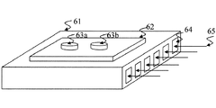
図9は電力増幅器の冷却機構を示す斜視図である。
電力増幅器のアンプ回路チップ63a,63bから熱が発生する。アンプ回路チップ63a,63bに密着した冷却フィン61には側面に空気溝64が設けられている。
この空気溝64に冷却用空気65を送って、冷却する。冷却機構は水冷方式ではなく、空冷方式にすることにより、装置の信頼性と簡便性を向上させる。
FIG. 9 is a perspective view showing a cooling mechanism of the power amplifier.
Heat is generated from the
Cooling
各電力増幅器31 〜3N は、それぞれ対応する一つのプラズマ発生装置41〜4Nを励起するので、広い領域をプラズマで洗浄する場合、多数のプラズマ発生装置41〜4Nを組み合わせて配置する。
この多数のプラズマヘッドの発生装置を励起するために、図1Aに示すとおり、電力増幅器31 〜3N を並列に構成する。
Each of the
In order to excite the multiple plasma head generators, the
以上説明したとおり、洗浄領域の大きさに対応するプラズマ発生装置の数および組み合わせの選択は極めて容易である。
図5にプラズマ発生装置群4をプラズマ発生装置41からプラズマ発生装置4Nまでの組み合わせで配置した例を示す。各プラズマ発生装置41〜4Nの同軸の上方からプラズマガスが供給されている。そして、各プラズマ発生装置41〜4Nの同軸の側面からマイクロ波が入力される。プラズマガスの洗浄の対象である試料400は、均一にプラズマガスに接触される。プラズマガスの中にプラズマの強度を検出する検出器41S〜4NSが配置されている。検出器は二本の深針の簡単な構造のラングミュア(Langmuir)プローブを用いる。この深針間に直流電圧を印加して、流れる電流を測定する。前記深針間に流れる電流を電圧に変換する。たとえば、プラズマ発生装置41に配置する検出器41Sから変換された電圧をD1とする。
As described above, it is very easy to select the number and combination of plasma generators corresponding to the size of the cleaning region.
FIG. 5 shows an example in which the plasma generator group 4 is arranged in combination from the
図6に制御回路5を示す。前記電圧D1は制御回路5でディジタル信号に変換され、制御信号CTDとCTPTに変換される。電圧D1は増幅器52で増幅され、マルチプレキサー53に入力される。このマルチプレキサー53により、D1からDNの電圧を直列の電圧列に並び替え、A/D変換器54に入力する。D1からDNの電圧をディジタルデータに変換する。
CPU56はこれらのディジタルデータを演算し、このディジタルデータをD/A変換器57により、アナログ電圧CTD1に変換する。このアナログ電圧CTD1は、図4Aに示す電力増幅器31 の入力端子3Bに入力され、これにより個別的にマイクロ波電力の強度を制御する。
FIG. 6 shows the
The
次に、この実施例においてはCTPT信号は、図1Aに示すように、全ての電力増幅装置3に対して同じ信号になる。図1AのCTPT信号は、マイクロ波変調回路2に接続されている。また、この実施例では、CTPT信号は、プラズマ発生装置全体の平均電力を規定することになる。その平均電力の制御は、プラズマ発生装置を使用する環境により、また、装置起動時および定常動作時等の電力制御の際に有効である。
一般的には、次の制御方法を選択する。
1)D1からDNの平均値からCTPT信号を決定する。

以上、図1Aに示したプラズマ発生装置の一例を説明した。
Next, in this embodiment, the CTPT signal is the same signal for all the
In general, the following control method is selected.
1) The CTPT signal is determined from the average value of D1 to DN.
The example of the plasma generator shown in FIG. 1A has been described above.
先に、マイクロ波発振器1の周波数制御について簡単に説明したが、最後にシステム全体の周波数制御について説明する。
図1A,図4Aで示す電力増幅器の各回路に方向性結合器が内蔵されている。
よってこの回路から周波数制御信号CFT1,,CFTnが出力される。図6に示す制御回路5の下部に示す回路がこのCFT1などの信号を処理する回路である。
この回路は、マルチプレキサー5E,増幅回路5F,D/A変換回路5G,制御用CPU5H,アナログスイッチ5Iと増幅回路5Jで構成される。
以下、この回路の動作について図16を参照して説明する。制御の方法は次の3通りがある。
1)プラズマ発生の条件を調査研究するために、周波数を細かく設定し、プラズマの発生を研究する段階でキー入力して実施する方法。この処理は図16に示す1の処理である。
2)CFT1からCFTnの信号の内のどれかを選択する方法。この処理は図16に示す2の処理である。
CFT1の入力端5Cから増幅器5Dにこの信号が入力される。マルチプレキサー5Eは、CPU5Hの制御信号SELAにより、CFT1からCFTnの信号の内の一つの信号を出力する。増幅回路5Fを通り、アナログスイッチ5Iに入力する。CPU5Hからの制御信号により、アナログスイッチ5Iは増幅回路5Fの出力信号をアナログスイッチ5Iの出力に伝達する。
この信号が増幅回路5Jをとおり、出力端5KにCFT制御信号を出力する。この制御信号CFTがマイクロ波発振器1の入力端14に印加され、発振周波数を制御する。
この負帰還制御により、一定の周波数に保持することができる。
CFT1からCFTnの信号のどれを選択するかはCPUまたはキーボードから決定できる。
3)CPUが一定のプログラムに従って周波数を制御する方法。この処理は図16に示す3の処理である。
プラズマ発生時の周波数とプラズマ発生後の温度変化により、周波数の変移を見込んで周波数をシフトし、発振の効果をあげる。
周波数のシフトはあらかじめ実験テストで測定しておき、プログラムにそのデータをプログラムする方法をとる。
この場合、CPU5HはD/A変換回路5Gにディジタルデータを転送し、D/A変換回路5Gの出力端にアナログ電圧を出力する。同時にCPU5Hからの制御信号SELBにより、アナログスイッチ5IはD/A変換回路5Gの出力信号をアナログスイッチ5Iの出力に伝達する。このCFT制御信号がマイクロ波発振器1の発振周波数を変える。
このようにCPUの制御を利用して、使用状態に対応した柔軟かつ複雑な制御を実行して、発振効率を上げることが可能になる。
First, the frequency control of the
A directional coupler is built in each circuit of the power amplifier shown in FIGS. 1A and 4A.
Therefore, frequency control signals CFT1, CFTn are output from this circuit. The circuit shown at the bottom of the
This circuit includes a multiplexer 5E, an
The operation of this circuit will be described below with reference to FIG. There are the following three control methods.
1) A method in which the frequency is set finely and key input is performed at the stage of studying plasma generation in order to investigate and study the conditions of plasma generation. This process is the
2) A method for selecting one of the signals from CFT1 to CFTn. This process is
This signal is input to the
This signal passes through the
By this negative feedback control, a constant frequency can be maintained.
Which of the CFT1 to CFTn signals is selected can be determined from the CPU or the keyboard.
3) A method in which the CPU controls the frequency according to a certain program. This process is the
The frequency is shifted in anticipation of the frequency shift by the frequency at the time of plasma generation and the temperature change after the plasma generation, thereby improving the oscillation effect.
The frequency shift is measured in advance by an experimental test, and the data is programmed in a program.
In this case, the
As described above, it is possible to increase the oscillation efficiency by executing the flexible and complicated control corresponding to the use state by using the control of the CPU.
次に本発明の第2の実施形態である図1Bに示した大気圧大面積プラズマ発生装置について説明する。この実施形態も図1Aに示した大気圧下でプラズマ生成用ガスを励起するマイクロ波励起プラズマガス発生装置と共通の目的と同様な機能をもつプラズマガス発生装置である。
マイクロ波発振器1は、発振周波数が可変なVCO回路を含むものである。
マイクロ波変調回路2もマイクロ波発振器1に接続されているマイクロ波の発振継続時間および発振間隔を可変とする変調器22とアイソレータ23と増幅器25とを含んでいる。
マイクロ波電力増幅装置3は、マイクロ波変調器2の出力に接続されている、ユニット化した複数のマイクロ波電力増幅器31 〜3N を含んでいる。
空洞共振器8は、図10,11に示されているように対向する細長いギャップで結合する一対の空洞8a,8bよりなり、前記ギャップ間に、前記ギャップに直交する方向にプラズマ生成用ガスを通過させる誘電体通路をもち、マイクロ波電力増幅器3 1 〜3 N からの電力を前記空洞に供給する結合アンテナ81〜8Nが前記ギャップの方向に沿って一方の空洞8aの空洞壁に配置されている。
また複数のプラズマセンサ81S〜8NSが、前記誘電体通路のプラズマガス排出口に配置されている。
制御回路5には前記プラズマセンサの出力が接続されており、マイクロ波の発振継続時間と発振周期を制御してマイクロ波変調器2の出力を制御する。制御回路5は、供給電力を制御するプログラムを有し、前記プログラムにしたがって制御信号をマイクロ波発振器1,マイクロ波変調器2またはマイクロ波電力増幅器3 1 〜3 N に接続する。
Next, the atmospheric pressure / large area plasma generator shown in FIG. 1B according to the second embodiment of the present invention will be described. This embodiment is also a plasma gas generator having the same function as the microwave-excited plasma gas generator that excites the plasma generating gas under the atmospheric pressure shown in FIG. 1A.
The microwave
As shown in FIGS. 10 and 11, the
A plurality of
The
制御回路5は、図1Aの実施形態で説明した回路と殆ど同じである。しかし若干相違する点があるので、以下相違点について補足する。
図1Bに示すプラズマアンテナで構成したマイクロ波プラズマ発生装置は、図1Aの電力増幅装置3と一部が異なる。
図4Bの回路には、位相制御回路33が付加されている。CPUを内蔵する制御回路39の制御信号により、位相制御回路33が働き、マイクロ波の位相を変化させる。
この装置の特徴は、プラズマ発生装置のエレメントが一列に配列されており、その間隔は、マイクロ波の導波管(チェンバ)内におけるマイクロ波管内波長の4分の1の長さ
(λg /4)に設定されている。当然エレメントの列の長さはマイクロ波管内波長λg に対して充分な長さになっている。
The
The microwave plasma generator configured by the plasma antenna shown in FIG. 1B is partially different from the
A
The characteristic of this apparatus is that the elements of the plasma generator are arranged in a line, and the distance between them is a length (λ g / 4) of the wavelength in the microwave tube in the microwave waveguide (chamber). 4). Naturally, the length of the row of elements is sufficiently long with respect to the wavelength λ g in the microwave tube.
前記プラズマ発生装置におけるプラズマ発生の前後のモードは、図11A,11Bと図12A,12Bに示されている。まず、プラズマが発生する前の電界モードでは、図11Aに示すように、電界はチェンバのスリット間に発生する。チェンバ内のQは高いので、電界に対して直角方向のアンテナで励起することで、カップリングを1に近くする。このことにより最大電力が供給され、プラズマ化を促進する。 The modes before and after plasma generation in the plasma generator are shown in FIGS. 11A and 11B and FIGS. 12A and 12B . First, an electric field mode before plasma is generated, as shown in FIG. 11 A, an electric field is generated between chambers slit. Since Q in the chamber is high, the coupling is brought close to 1 by exciting with an antenna perpendicular to the electric field. As a result, the maximum power is supplied and the plasma is promoted.
次にプラズマが発生した後の電界モードでは、図12Aに示すように、電界はアンテナ側とチェンバのスリット間に発生する。プラズマが発生しているので、チェンバ内のQは低くなる。この電界はアンテナと同じ方向で励起されるので、カップリングはまたほぼ1に近くなる。このことにより電力がアンテナから充分供給され、強いプラズマが維持される。
前記プラズマ発生装置におけるプラズマ発生前の等価回路は、図11Bに示す回路で表される。チェンバ内のQは非常に高く、コンダクタンスG1 は極めて小さい。このときの共振周波数はω1 で、QはQ1 である。アンテナ出力がチェンバに電力を供給するときの結合係数はk1 である。プラズマ発生後の等価回路は、図12Bに示す回路で表される。プラズマが発生すると、チェンバ内のコンダクタンスG2 は大きくなる。このときの共振周波数はω2 で、QはQ2 となる。
本発明では、条件(ω1 ≒ω2 )と条件(k2 /k1 )≒(G2 /G1 )を満足するように、アンテナの形状とチェンバの形状を最適化することが重要である。
この回路条件の最適化で、プラズマ発生の前後で共振周波数が一定に保たれ、プラズマが安定に維持される。プラズマ発生前後で、前述した電界モードが変化することにより、条件が満足させられる。
このようにこのプラズマ発生装置の構造は、プラズマ発生に適した構造であることが特徴である。
Next, in the electric field mode after the plasma is generated, an electric field is generated between the antenna side and the slit of the chamber, as shown in FIG. 12A. Since plasma is generated, the Q in the chamber becomes low. Since this electric field is excited in the same direction as the antenna, the coupling is also close to unity. As a result, sufficient electric power is supplied from the antenna, and strong plasma is maintained.
The equivalent circuit before plasma generation in the plasma generator is represented by the circuit shown in FIG. 11B. The Q in the chamber is very high and the conductance G 1 is very small. At this time, the resonance frequency is ω 1 and Q is Q 1 . The coupling coefficient when the antenna output supplies power to the chamber is k 1 . The equivalent circuit after plasma generation is represented by the circuit shown in FIG. 12B. When plasma is generated, the conductance G 2 in the chamber increases. The resonance frequency at this time is ω 2 and Q is Q 2 .
In the present invention, it is important to optimize the antenna shape and the chamber shape so that the condition (ω 1 ≈ω 2 ) and the condition (k 2 / k 1 ) ≈ (G 2 / G 1 ) are satisfied. Oh Ru.
By optimizing the circuit conditions, the resonance frequency is kept constant before and after plasma generation, and the plasma is maintained stably. The condition is satisfied by changing the electric field mode described above before and after the plasma generation.
Thus, the structure of this plasma generator is characterized by a structure suitable for plasma generation.
図4Bは本発明による第2の実施形態である大気圧大面積プラズマ発生装置における電力増幅装置を示す回路図である。この回路は図4Aに示されている回路の他に位相制御回路33が付加されている。図6に示したCPUを内蔵する制御回路39の制御信号により、位相制御回路33が働き、マイクロ波の位相を変化させる。この装置の特徴は、図13上段に示すように、プラズマアンテナが一列に配列しており、その間隔は、マイクロ波のチェンバ内におけるマイクロ波波長の4分の1の長さλg /4に設定する。この間隔により、チェンバ内部の定在波の波形は、図13下段に示すように、隣同士のアンテナの定在波の位相差は90度になるので隣同士のアンテナの干渉の影響を抑えることができる。しかし、プラズマ発生前後におけるチェンバ内のインピーダンスの変化により定在波の位相が変わるので、これを制御するために位相制御回路33により位相調整を実行する。また一定時間の電界の平均は、チェンバの長さ方向(エレメントの列の長さ方向)に対して一定になる特徴がある。このことは、チェンバの長さ方向に対して電力が一定になることを示し、試料に一様な照射が可能になる。
当然アンテナエレメントの列の長さはマイクロ波波長λg に対して充分な長さになっている。よって壁側からの反射波は少なくなる。
前記プラズマ発生装置に使用するアンテナは、モノポールアンテナ、誘電体ホーンアンテナ、パッチアンテナ、ヘリカルアンテナなど使用できる。
FIG. 4B is a circuit diagram showing a power amplifying device in the atmospheric pressure / large area plasma generator according to the second embodiment of the present invention. In this circuit, a
Of course the length of the row of antenna elements has a sufficient length to microwave wavelength lambda g. Therefore, the reflected wave from the wall side is reduced.
The antenna used for the plasma generator can be a monopole antenna, a dielectric horn antenna, a patch antenna, a helical antenna, or the like.
(第1の実施形態の利用例)図14は、本発明の第1の実施形態(図1A)である広い領域を短時間でプラズマ洗浄するマイクロ波プラズマ発生源に応用した例の斜視図である。図15Aは他の応用例を示す斜視図である。
各応用例において、複数のマイクロ波プラズマ発生源(同軸共振器)41・・・を支持構造7により特定の空間に向けて配列してある。
図14に示す先の例では導波管状の支持構造7で、複数のマイクロ波プラズマ発生源(同軸共振器)41,42・・を直線上に配置してある。
図15Aに示す例では、複数のマイクロ波プラズマ発生源(同軸共振器)41・・を支持構造7により円盤状に配置し、広い領域を同時に洗浄するプラズマ発生装置を形成している。この場合、大規模なエレメントを必要とするが、短時間で洗浄できるプラズマ発生装置が構築できる。
図15Bに示す例では、複数プラズマアンテナで構成するマイクロ波プラズマ発生源(同軸共振器)41・・を支持構造7により円盤状に配置し、各プラズマアンテナ間の距離をほぼ管内波長の4分の1の長さλg /4に配置して、広い領域を同時に洗浄するプラズマ発生装置を形成している。この場合、大規模なエレメントを必要とするが、短時間で洗浄できるプラズマ発生装置が構築できる。
(Application Example of the First Embodiment) FIG. 14 is a perspective view of an example applied to a microwave plasma generation source that cleans a wide area in a short time according to the first embodiment (FIG. 1A) of the present invention. is there. FIG. 15A is a perspective view showing another application example.
In each application example, a plurality of microwave plasma generation sources (coaxial resonators) 41... Are arranged by a
In the previous example shown in FIG. 14, a plurality of microwave plasma generation sources (coaxial resonators) 41, 42,...
In the example shown in FIG. 15A, a plurality of microwave plasma generation sources (coaxial resonators) 41... Are arranged in a disk shape by the
In the example shown in FIG. 15B, microwave plasma generation sources (coaxial resonators) 41... Constituted by a plurality of plasma antennas are arranged in a disk shape by the
以上詳しく説明した2つの実施形態に係る装置は、装置を小形化で携帯性に優れた構成とすることができるので、広範囲の応用が可能になる。 The devices according to the two embodiments described in detail above can be applied to a wide range of applications because the devices can be downsized and have excellent portability.
本発明のマイクロ波プラズマ発生装置において、マイクロ波発生源は固体素子を利用することができ、小形化、高い信頼性、長い寿命のマイクロ波プラズマ発生装置が得られる。またマイクロ波用LDMOSなどの固体素子で回路構成するので、高い変換効率で動作させることができる。機械的な付属回路もなく、小形で高出力であり、広い分野に利用できる。
特にプラズマ励起用マイクロ波電力は、固体素子で構成する電力増幅器から供給することにより、マイクロ波発振器の発振出力電力は数ミリワット台の少ない電力で済み、安定した発振が得られる。
前記マイクロ発生源は固体発振器とすることもできるから、装置を一層小形にすることができ、全体を可搬形に構成することもできる。
大気圧に近いガスをマイクロ波で励起させプラズマガスを発生するマイクロ波プラズマ発生装置であって、取り扱いが容易であり、安定した動作ができる。
In the microwave plasma generation apparatus of the present invention, a solid-state element can be used as the microwave generation source, and a microwave plasma generation apparatus having a small size, high reliability, and a long lifetime can be obtained. In addition, since the circuit is composed of a solid-state element such as a microwave LDMOS, it can be operated with high conversion efficiency. There is no mechanical ancillary circuit, and it is small and has high output and can be used in a wide range of fields.
In particular, when the microwave power for plasma excitation is supplied from a power amplifier composed of a solid state device, the oscillation output power of the microwave oscillator can be as low as several milliwatts, and stable oscillation can be obtained.
Since the micro-generation source can be a solid-state oscillator, the apparatus can be further miniaturized and the whole can be configured to be portable.
A microwave plasma generator that generates a plasma gas by exciting a gas close to atmospheric pressure with a microwave, is easy to handle, and can operate stably.
次に、電力増幅器31 では、交流電源を内蔵し、この交流電圧を直流電圧に変換して、電力増幅器31 で使用される最大消費直流電力を供給している。
一つの電力増幅器31 内に交流電源を内蔵するので、広い領域のプラズマ洗浄の要望にたいしてプラズマ発生装置の増設すなわち電力増幅器31 ・・の増設が必要になるときに、交流電源の新設は不要である。
多様なプラズマ洗浄にたいして、プラズマ発生装置は、規格化された電力増幅器ユニットを挿入するだけの簡単な操作で対応できるという利点がある。
Next, the
Since an AC power supply is built into one
For various types of plasma cleaning, the plasma generator has the advantage that it can be handled with a simple operation by simply inserting a standardized power amplifier unit.
一つの電力増幅器内に交流電源を内蔵する手段により、広い領域のプラズマ洗浄の要望にたいしてプラズマ発生装置の増設すなわち電力増幅器の増設が必要になるときに、交流電源の新設は不要である。
洗浄領域の大きさにより、プラズマ発生装置の数を増加しても、それに伴う電力増幅器のユニット数だけ増やして簡単に対応できる特徴がある。
When it is necessary to increase the number of plasma generators, that is, to increase the number of power amplifiers in response to the demand for plasma cleaning in a wide area by means of incorporating an AC power source in one power amplifier, it is not necessary to newly install an AC power source.
Depending on the size of the cleaning region, even if the number of plasma generators is increased, the number of power amplifier units associated therewith can be easily increased.
本発明による大気圧大面積プラズマ発生装置は、工業素材の溶融、溶断加工、接合、精製、治金、スプレイなどの工業素材の加工分野、プラズマの発生する光を利用するディスプレイのための光源などの照明分野、微粒子生成、誘導プラズマをイオン化の手段とする微量試料成分の化学分析の分析分野、半導体プロセスの材料における表面処理の洗浄分野に広く利用できる。 The atmospheric pressure large area plasma generator according to the present invention is a processing field of industrial materials such as melting, fusing, joining, refining, metallurgy, and spraying of industrial materials, a light source for a display using light generated by plasma, etc. It can be widely used in the field of illumination, the generation of fine particles, the field of chemical analysis of trace sample components using induced plasma as ionization means, and the field of surface treatment cleaning in semiconductor process materials.
1 マイクロ波発振器
2 マイクロ波変調回路
3 電力増幅装置
4 プラズマ発生装置群
5 制御回路
6 手動操作用キーボード
7 支持構造
8 空洞共振器
8a,8b 上空洞,下空洞
81〜8N 空洞励起アンテナ
81S〜8NS 検出器(プラズマセンサ)
13 発振回路
14 周波数制御信号CFTの入力端
15 増幅器
16 出力端
21 マイクロ波変調回路の入力端
23 アイソレータ
25 増幅器
26 マイクロ波変調回路の出力端
31 電力増幅器の入力端
32 減衰器
33 位相制御回路
34,35 増幅器
36 アイソレータ
37 方向性結合器
38 電力増幅器の出力端
39 制御回路
3A 交流直流電圧変換回路
3B 制御信号CTDの入力端
3C 交流電圧の入力端
3D マイクロ波周波数の制御回路
3E CFT制御信号出力端
40 プラズマガス供給装置
41,42,・・・,4N プラズマ発生装置
41S,42S,・・・,4NS 検出器(プラズマセンサ)
400 試料
51 D1信号入力端
52 増幅器
53 マルチプレキサー
54 A/D変換回路
55 CPU内蔵の制御回路
56 CPU
57 D/A変換回路
59 CTPT信号出力端
5A バッファ
5B CTD1の出力端
5C CFT1の入力端
5D 増幅器
5E マルチプレキサー
5F 増幅器
5G D/A変換回路
5H CPU
5I アナログスイッチ回路
5J 増幅器
5K CFT出力端
61 冷却フィン
62 電力増幅器
63a,63b アンプ回路チップ
64 空気溝
65 冷却用空気
1707 マイクロ波発振器
1708 アイソレータ
1710 マイクロ波導波管
1711 パルスモータ制御の3スタブチューナ
DESCRIPTION OF
DESCRIPTION OF SYMBOLS 13
400
53 Multiplexer
54 A / D conversion circuit
55 Control circuit with built-in CPU
56 CPU
57 D / A converter circuit
59
5I
Claims (7)
発振周波数が可変なVCO回路を含むマイクロ波発振器と、
前記マイクロ波発振器に接続され、前記マイクロ波発振器によって出力されるマイクロ波の発振継続時間および発振間隔を可変とするパルス回路とアイソレータと増幅器を含むマイクロ波変調器と、
前記マイクロ波変調器の出力に接続されているユニット化した複数のマイクロ波電力増幅器と、
空洞内または、空洞の一部にプラズマ生成用ガスが導入され、マイクロ波電力増幅器からの電力を前記空洞に供給する複数の結合アンテナが空洞壁に配置されている空洞共振器と、
前記空洞共振器の複数のアンテナとプラズマガス生成位置に関連して配置されている複数のプラズマセンサと、
複数のマイクロ波プラズマ発生源に入射する進行波と前記マイクロ波プラズマ発生源が反射する反射波の位相を測定して前記マイクロ波発振器の発振周波数が前記複数のマイクロ波プラズマ発生源のうちの1つのマイクロ波プラズマ発生源の共振周波数と一致するように制御する共振維持制御部、前記プラズマセンサの出力または指定された値のいずれかに従ってマイクロ波の発振継続時間と発振間隔を調整する前記パルス回路を制御して全体の出力電圧を維持する電圧維持制御部、および前記マイクロ波プラズマ発生源に関連して配置されたプラズマセンサの測定結果に従って前記マイクロ波電力増幅器を制御し、特定の空間のプラズマ状況に応じて前記マイクロ波変調器によって出力されたマイクロ波の振幅を増幅する電力調整制御部を設けた制御装置と、
から構成する大気圧大面積プラズマ発生装置。 A microwave-excited plasma gas generator for exciting a plasma generating gas under atmospheric pressure,
A microwave oscillator including a VCO circuit having a variable oscillation frequency;
A microwave modulator including a pulse circuit, an isolator, and an amplifier connected to the microwave oscillator and configured to vary the oscillation duration and the oscillation interval of the microwave output by the microwave oscillator;
A plurality of unitized microwave power amplifiers connected to the output of the microwave modulator;
A cavity resonator in which a plasma generating gas is introduced into the cavity or a part of the cavity, and a plurality of coupled antennas for supplying power from the microwave power amplifier to the cavity are disposed on the cavity wall;
A plurality of antennas and a plurality of plasma sensors arranged in relation to plasma gas generation positions of the cavity resonator;
Wherein the traveling wave incident microwave plasma source of several microwave plasma generating source by measuring the phase of the reflected wave reflected oscillation frequency of the microwave oscillator of the plurality of microwave plasma source Resonance maintenance control section that controls to match the resonance frequency of one microwave plasma generation source, and the pulse that adjusts the oscillation duration and the oscillation interval of the microwave according to either the output of the plasma sensor or a specified value voltage maintenance control unit to maintain the overall output voltage by controlling the circuit, and the microwave power amplifier control according to the measurement results of plasma sensors arranged in connection with the microwave plasma source, the space specific A power adjustment control unit for amplifying the amplitude of the microwave output by the microwave modulator according to the plasma state of And a control device digits,
An atmospheric pressure large area plasma generator.
発振周波数が可変なVCO回路を含むマイクロ波発振器と、
前記マイクロ波発振器に接続され、前記マイクロ波発振器によって出力されるマイクロ波の発振継続時間および発振間隔を可変とするパルス回路とアイソレータと増幅器を含むマイクロ波変調器と、
前記マイクロ波変調器の出力に接続されているユニット化した複数のマイクロ波電力増幅器と、
対向する細長いギャップで結合する一対の空洞よりなり、前記ギャップ間に前記ギャップに直交する方向にプラズマ生成用ガスを通過させる誘電体通路をもち、マイクロ波電力増幅器からの電力を前記空洞に供給する複数の結合アンテナが空洞壁に配置されている空洞共振器と、
前記誘電体通路のプラズマガス排出口に配置されている複数のプラズマセンサと、
前記プラズマセンサの出力が接続されており、
複数のマイクロ波プラズマ発生源に入射する進行波と前記マイクロ波プラズマ発生源が反射する反射波の位相を測定して前記マイクロ波発振器の発振周波数が前記複数のマイクロ波プラズマ発生源のうちの1つのマイクロ波プラズマ発生源の共振周波数と一致するように制御する共振維持制御部、前記プラズマセンサの出力または指定された値のいずれかに従ってマイクロ波の発振継続時間と発振間隔を調整する前記パルス回路を制御して全体の出力電圧を維持する電圧維持制御部、および前記マイクロ波プラズマ発生源に関連して配置されたプラズマセンサの測定結果に従って前記マイクロ波電力増幅器を制御し、特定の空間のプラズマ状況に応じて前記マイクロ波変調器によって出力されたマイクロ波の振幅を増幅する電力調整制御部を設けた制御装置と、
から構成する大気圧大面積プラズマ発生装置。 A microwave-excited plasma gas generator for exciting a plasma generating gas under atmospheric pressure,
A microwave oscillator including a VCO circuit having a variable oscillation frequency;
A microwave modulator including a pulse circuit, an isolator, and an amplifier connected to the microwave oscillator and configured to vary the oscillation duration and the oscillation interval of the microwave output by the microwave oscillator;
A plurality of unitized microwave power amplifiers connected to the output of the microwave modulator;
It is composed of a pair of cavities coupled by opposing elongated gaps, and has a dielectric passage for passing a plasma generating gas in a direction perpendicular to the gap between the gaps, and supplies power from the microwave power amplifier to the cavities. A cavity resonator in which a plurality of coupled antennas are disposed on the cavity wall;
A plurality of plasma sensors arranged at the plasma gas outlet of the dielectric passage;
The output of the plasma sensor is connected;
The phase of the traveling wave incident on the plurality of microwave plasma generation sources and the reflected wave reflected by the microwave plasma generation source are measured, and the oscillation frequency of the microwave oscillator is one of the plurality of microwave plasma generation sources. Resonance maintenance control unit that controls to match the resonance frequency of two microwave plasma generation sources, and the pulse circuit that adjusts the oscillation duration and interval of microwaves according to either the output of the plasma sensor or a specified value A voltage maintaining controller that controls the entire output voltage by controlling the microwave power amplifier according to a measurement result of a plasma sensor disposed in association with the microwave plasma generation source, and plasma in a specific space A power adjustment control unit that amplifies the amplitude of the microwave output by the microwave modulator according to the situation. And a control device digits,
An atmospheric pressure large area plasma generator.
Priority Applications (1)
| Application Number | Priority Date | Filing Date | Title |
|---|---|---|---|
| JP2004344205A JP4035568B2 (en) | 2004-11-29 | 2004-11-29 | Atmospheric pressure large area plasma generator |
Applications Claiming Priority (1)
| Application Number | Priority Date | Filing Date | Title |
|---|---|---|---|
| JP2004344205A JP4035568B2 (en) | 2004-11-29 | 2004-11-29 | Atmospheric pressure large area plasma generator |
Publications (2)
| Publication Number | Publication Date |
|---|---|
| JP2006156100A JP2006156100A (en) | 2006-06-15 |
| JP4035568B2 true JP4035568B2 (en) | 2008-01-23 |
Family
ID=36634124
Family Applications (1)
| Application Number | Title | Priority Date | Filing Date |
|---|---|---|---|
| JP2004344205A Expired - Fee Related JP4035568B2 (en) | 2004-11-29 | 2004-11-29 | Atmospheric pressure large area plasma generator |
Country Status (1)
| Country | Link |
|---|---|
| JP (1) | JP4035568B2 (en) |
Cited By (1)
| Publication number | Priority date | Publication date | Assignee | Title |
|---|---|---|---|---|
| KR101044314B1 (en) * | 2008-11-25 | 2011-06-29 | 포항공과대학교 산학협력단 | Hemostatic device using low temperature plasma |
Families Citing this family (13)
| Publication number | Priority date | Publication date | Assignee | Title |
|---|---|---|---|---|
| JP5278639B2 (en) * | 2006-12-14 | 2013-09-04 | 凸版印刷株式会社 | Plasma assisted deposition system |
| JP4609440B2 (en) * | 2007-02-21 | 2011-01-12 | パナソニック株式会社 | Atmospheric pressure plasma generator and ignition method |
| JP2008210598A (en) * | 2007-02-26 | 2008-09-11 | Nagano Japan Radio Co | Matching device for plasma processing apparatus, plasma processing apparatus, and matching method |
| DE102007020419A1 (en) * | 2007-04-27 | 2008-11-06 | Forschungsverbund Berlin E.V. | Electrode for plasma generator |
| JP5026169B2 (en) * | 2007-07-04 | 2012-09-12 | 長野日本無線株式会社 | Plasma processing equipment |
| WO2009012735A1 (en) * | 2007-07-23 | 2009-01-29 | Hüttinger Elektronik Gmbh + Co. Kg | Plasma supply device |
| KR101479374B1 (en) | 2008-09-20 | 2015-01-12 | 트럼프 헛팅거 게엠베하 + 코 카게 | Plasma power supply arrangement |
| GB0902784D0 (en) | 2009-02-19 | 2009-04-08 | Gasplas As | Plasma reactor |
| NO339087B1 (en) | 2010-08-17 | 2016-11-14 | Gasplas As | Apparatus, system and method for producing hydrogen |
| CN103607835A (en) * | 2013-11-19 | 2014-02-26 | 安徽理工大学 | Atmospheric pressure low power pulse microwave cold plasma jet flow generating device |
| US10748745B2 (en) * | 2016-08-16 | 2020-08-18 | Applied Materials, Inc. | Modular microwave plasma source |
| KR102469600B1 (en) * | 2018-12-03 | 2022-11-22 | 가부시키가이샤 아루박 | Film formation device and film formation method |
| CN114867180B (en) * | 2022-05-23 | 2024-12-17 | 安徽工业大学 | Dual-channel atmospheric pressure microwave plasma jet device |
-
2004
- 2004-11-29 JP JP2004344205A patent/JP4035568B2/en not_active Expired - Fee Related
Cited By (1)
| Publication number | Priority date | Publication date | Assignee | Title |
|---|---|---|---|---|
| KR101044314B1 (en) * | 2008-11-25 | 2011-06-29 | 포항공과대학교 산학협력단 | Hemostatic device using low temperature plasma |
Also Published As
| Publication number | Publication date |
|---|---|
| JP2006156100A (en) | 2006-06-15 |
Similar Documents
| Publication | Publication Date | Title |
|---|---|---|
| JP4035568B2 (en) | Atmospheric pressure large area plasma generator | |
| CN110383944B (en) | Microwave applicator with solid state generator power source | |
| KR102346036B1 (en) | Plasma processing device and plasma processing method | |
| Hornstein et al. | Continuous-wave operation of a 460-GHz second harmonic gyrotron oscillator | |
| KR101560122B1 (en) | Surface wave plasma processing apparatus | |
| KR101490572B1 (en) | Electromagnetic-radiation power-supply mechanism and microwave introduction mechanism | |
| JP5208547B2 (en) | Power combiner and microwave introduction mechanism | |
| US10510513B2 (en) | Plasma processing device and high-frequency generator | |
| Lawson et al. | Performance characteristics of a high-power X-band two-cavity gyroklystron | |
| JP2006128075A (en) | High-frequency heating device, semiconductor manufacturing device, and light source device | |
| JP2004055614A (en) | Plasma processing apparatus | |
| KR102024973B1 (en) | Plasma processing apparatus and high frequency generator | |
| JP2006287817A (en) | Microwave generating device, microwave supplying device, plasma treatment device and microwave generating method | |
| JP3839395B2 (en) | Microwave plasma generator | |
| JP3787297B2 (en) | Plasma processing equipment | |
| JP4022590B2 (en) | Microwave plasma generator | |
| JP2004200113A (en) | Microwave plasma generation device | |
| JP3856153B1 (en) | Magnetron oscillator | |
| US20030214651A1 (en) | Method and apparatus for atomic emission spectroscopy | |
| JP2007082172A (en) | Magnetron oscillation device | |
| KR100500360B1 (en) | High efficient-atmospheric microwave plasma system | |
| Marz et al. | Microwave excitation of a diffusion-cooled CO2 laser | |
| JP2007299652A (en) | Plasma generator, and work processor | |
| US20020122445A1 (en) | Laser with substantially uniform microwave excitation | |
| Einat et al. | Anomalous free electron laser interaction |
Legal Events
| Date | Code | Title | Description |
|---|---|---|---|
| A977 | Report on retrieval |
Free format text: JAPANESE INTERMEDIATE CODE: A971007 Effective date: 20061127 |
|
| A131 | Notification of reasons for refusal |
Free format text: JAPANESE INTERMEDIATE CODE: A131 Effective date: 20061205 |
|
| A521 | Written amendment |
Free format text: JAPANESE INTERMEDIATE CODE: A523 Effective date: 20070205 |
|
| A131 | Notification of reasons for refusal |
Free format text: JAPANESE INTERMEDIATE CODE: A131 Effective date: 20070612 |
|
| A521 | Written amendment |
Free format text: JAPANESE INTERMEDIATE CODE: A523 Effective date: 20070809 |
|
| TRDD | Decision of grant or rejection written | ||
| A01 | Written decision to grant a patent or to grant a registration (utility model) |
Free format text: JAPANESE INTERMEDIATE CODE: A01 Effective date: 20070904 |
|
| A61 | First payment of annual fees (during grant procedure) |
Free format text: JAPANESE INTERMEDIATE CODE: A61 Effective date: 20070910 |
|
| R150 | Certificate of patent or registration of utility model |
Free format text: JAPANESE INTERMEDIATE CODE: R150 |
|
| FPAY | Renewal fee payment (event date is renewal date of database) |
Free format text: PAYMENT UNTIL: 20101109 Year of fee payment: 3 |
|
| FPAY | Renewal fee payment (event date is renewal date of database) |
Free format text: PAYMENT UNTIL: 20111109 Year of fee payment: 4 |
|
| FPAY | Renewal fee payment (event date is renewal date of database) |
Free format text: PAYMENT UNTIL: 20121109 Year of fee payment: 5 |
|
| FPAY | Renewal fee payment (event date is renewal date of database) |
Free format text: PAYMENT UNTIL: 20131109 Year of fee payment: 6 |
|
| R250 | Receipt of annual fees |
Free format text: JAPANESE INTERMEDIATE CODE: R250 |
|
| R250 | Receipt of annual fees |
Free format text: JAPANESE INTERMEDIATE CODE: R250 |
|
| R250 | Receipt of annual fees |
Free format text: JAPANESE INTERMEDIATE CODE: R250 |
|
| LAPS | Cancellation because of no payment of annual fees |