JP4029134B2 - Projection exposure equipment - Google Patents
Projection exposure equipment Download PDFInfo
- Publication number
- JP4029134B2 JP4029134B2 JP1764897A JP1764897A JP4029134B2 JP 4029134 B2 JP4029134 B2 JP 4029134B2 JP 1764897 A JP1764897 A JP 1764897A JP 1764897 A JP1764897 A JP 1764897A JP 4029134 B2 JP4029134 B2 JP 4029134B2
- Authority
- JP
- Japan
- Prior art keywords
- mark
- reference mark
- position detection
- detection system
- optical system
- Prior art date
- Legal status (The legal status is an assumption and is not a legal conclusion. Google has not performed a legal analysis and makes no representation as to the accuracy of the status listed.)
- Expired - Fee Related
Links
Images


Landscapes
- Exposure Of Semiconductors, Excluding Electron Or Ion Beam Exposure (AREA)
Description
【0001】
【発明の属する技術分野】
本発明は基板用投影露光装置に関し、特にステージ座標系に基準マークを備えた、大型の液晶パネル等の製造に用いられる基板用投影露光装置に関する。
【0002】
【従来の技術】
大型液晶パネル等の露光装置の基準位置は、基板ステージ上に配置した基準マークにより定められ、その基準マークにより、投影光学系を通してレチクル即ち原版のアライメントマークと照合され、ステージ座標系における投影光学系を介したレチクルの位置が求められる。
【0003】
更に、露光装置はプレートアライメント系を有しており、プレート即ち感光性基板に2層目以上を露光する際には、1層目に露光されたプレートの位置を検出するため、基準マークを用いて、そのプレートアライメント系の位置を検出する。
【0004】
このようにして、いわゆる露光装置におけるプレートアライメント系のベースラインが求まる。ベースラインとは、対象物あるいは対象の系の位置を、ステージ座標系の座標で表示したものであり、投影光学系の基準位置に対するベクトル表示の一種である。
【0005】
一般には露光前に上記工程を経て、基板ステージ上に搬入されたプレート上のプレートアライメントマークをプレートアライメント系で観察しその位置を計測し、上記ベースラインの値を用いてプレートの位置合わせを行い、2層目以降の露光を開始する。しかし特に大きな、しかも角形の基板の露光装置では、プレートを載置する基板ステージの位置に上下動する基準マークを設け、プレートが載置されていないときにその基準マークを上にアップさせてベースラインを計測し、載置されているときは下に退避させるようにしている。この構造により、ステージの大型化を避け、コストを低減し精度を高めることができる。
【0006】
また特に複数枚のレチクルにて1画面を構成する液晶パネル等の露光装置では、その複数枚のレチクルの位置を、レチクルを交換しながら、各レチクル毎にアップした基準マークを用いて計測し、先に述べたプレートアライメント系の位置と各レチクルの位置をステージ座標系にて検出し、いわゆる各レチクル毎のベースラインを求めている。
【0007】
各レチクルの位置を検出する方法は、例えば、特開昭61−143760のように、ステージ上に設けられた基準マークとその下方に設けられた受光センサとにより、レチクル上の位置検出用のレチクルマークとの相対位置を検出したり、特開昭63−284814のように、基準マーク上のスリットマークをステージ側より発光し、投影光学系を介して、レチクル上のスリットマークとの相対位置を照明光学系内にある受光センサにて検出する方法などがある。
【0008】
【発明が解決しようとする課題】
しかしながら上記従来の技術において、例えば4枚のレチクルを用いる場合は、レチクルを交換する時間とプレートアライメント系の位置を検出する時間とがかかり、更に、レチクル上の異物検査等の時間を加えるとかなりの時間を要する。加えて最近は、デバイスの最適化、パネルの大型化等により、レチクル枚数も4枚が普通であったものが、6枚が必要になり、さらに多く必要とするようになりつつある。そこで、基準マークをアップしてレチクルマーク、プレートアライメント系等の位置を検出する場合に、各レチクルの位置とプレートアライメント系の位置とを計測する時間がかなり長くなり、基準マーク自体が上下動する機構であるためにステージの移動等により力が加わったり、ステージの移動等による熱的な要因を受け、基準マーク自体がドリフトを生じ、計測値が時間が経てば経つほど変化してしまうと言った問題を生じてしまった。
【0009】
また、この種の露光装置は、基板の端に位置する端子部にプレートアライメントマークを配置し、更に露光装置のスループットを上げるために概ねアライメントマークの位置する近傍に複数のいわゆるオフアクシスのプレートアライメント系を有する構成をとる。例えば、アライメントマークを基板の4隅に設けた場合、そのアライメントマーク間の寸法と同じ寸法にて、4つのプレートアライメント系の間隔を設定すればステージの移動を伴わずに、アライメントを完了することが可能になり、装置のスループットに有利となる。この場合にステージストロークを決定するものは、各プレートアライメント系の位置に対して、基準マークを移動させる場合となる。この場合には、基準マークを2個以上ステージ上に配置することによりステージストロークを小さくすることも可能になる。従来、この2つの基準マークの位置(間隔)を計測する場合は、1つのレチクルの同一マークを用いて検出されていた。このレチクルは、ステージの移動によって生ずるヨーイングの影響を補正するように、ステージの回転量を計測する、いわゆるヨーイング干渉計にて計測された値だけ回転され、その回転は、独立したレチクルのアライメント系にフィードバックされ、レチクルアライメント系にて制御される。また、近年では、レチクルステージ上の位置を計測するようなレチクル干渉計によって制御を行う場合もある。このような場合、2つの基準マークの計測には、レチクルのアライメントを行った時の計測誤差、制御誤差を発生することになる。
【0010】
以上のように本発明は、複数のレチクルにおいてベースラインを計測する場合に経時的に生じ得る基準マークの変化、いわゆるドリフト量を、無視または影響をごく小さくすることを目的とする。
【0011】
【課題を解決するための手段】
上記目的を達成するために、請求項1に係る発明による投影露光装置は、図2に示されるように、所定のパターンが形成された原版121を露光光によって照明する露光用照明系100と、該露光用照明系によって照明された前記原版上のパターン像を感光性基板202(図1)上に形成する投影光学系112とを備え、前記原版上のパターンを前記感光性基板上に露光する投影露光装置において;前記感光性基板を載置すると共に前記投影光学系の像面に沿って移動する基板ステージ201と;前記基板ステージに設けられた基準マーク141と;前記感光性基板の位置を検出すると共に前記基準マークに対する位置を検出する第1の位置検出系131(図1)と;前記基準マーク141と前記原版121との相対位置を検出する第2の位置検出系と;パターンの投影のために前記原版が載置される位置と前記投影光学系との間に固設された固定マーク151と;前記基準マークと前記固定マークとの相対位置を検出する第3の位置検出系と;前記第3の位置検出系にて得られる前記基準マークと前記固定マークとの相対位置に関する情報に基づいて、前記第1の位置検出系から出力される基準マークと感光性基板との相対位置に関する第1の基準マーク検出信号と、前記第2の位置検出系から出力される前記基準マークと前記原版との相対位置に関する第2の基準マーク検出信号との少なくとも一方を補正する信号補正系と;を備えたことを特徴とする。
【0012】
このように構成すると、固定マーク、第3の位置検出系及び信号補正系を備えるので、基準マークのドリフトによる測定誤差が補正される。
【0013】
請求項2に係る発明による投影露光装置は、請求項1に記載の装置に加えて、前記投影光学系の物体面に複数の前記原版を順次設定する原版交換装置をさらに設け;前記信号補正系は、前記原版交換装置を介して前記複数の原版が順次設定される毎に、前記第3の位置検出系にて得られる前記基準マークと前記固定マークとの相対位置に関する複数の情報に基づいて補正量を算出し、該補正量に基づいて前記第2の位置検出系にて前記各原版毎に得られる前記第2の基準マーク出力信号と前記第1の位置検出系にて得られる前記第1の基準マーク出力信号との少なくとも一方を補正することを特徴とする。
【0014】
この発明では、図6のグラフに示されるように、信号補正系が第3の位置検出系にて得られる複数の情報に基づいて算出された補正量に基づいて、各原版毎に得られる第2の基準マーク出力信号または第1の基準マーク出力信号を補正するので、基準マークのドリフトによる測定誤差が、さらに細かく補正される。即ち、原版である各レチクル毎に固定マークを用いてキャリブレーションを行うことにより、その複数枚のレチクルにてベースラインを計測した場合のドリフトの影響は、レチクル1枚分の、しかも固定マークと基準マークの計測とそのレチクルにて計測される最後の計測の間の極短期間しか影響を受けないことになる。また、固定マークの位置を計測した値を用いて、その間を補間することができ、更に詳細なドリフト量を推定し補正できる。
【0015】
さらに請求項3に記載の発明に係る投影露光装置のように、基準マークは、投影光学系の像面から退避して前記基板ステージ内部に収納されるように構成してもよい(図1参照)。
【0016】
このように構成すると、基板が載置されるべき基板ステージの位置に基準マークを設けることができるので、ステージの大型化ひいては装置全体の大型化を避けることができる。
【0017】
請求項4に係る発明による投影露光装置は、図2または図11に示されるように、請求項1乃至請求項3の装置に加えて、第3の位置検出系は、前記第2の位置検出系と共用する前記基準マーク照明系を有し;該基準マーク照明系は、前記第2の位置検出系にて前記基準マークと前記原版との相対位置を検出する際には、露光波長を持つ光によって前記原版上に形成された原版マークを前記投影光学系を介して照明し;前記第3の位置検出系にて前記基準マークと前記固定マークとの相対位置を検出する際には、露光波長を持つ光によって前記固定マークを前記投影光学系を介して照明することを特徴とする。
【0018】
請求項5に係る発明による投影露光装置では、図2に示されるように、請求項4に記載の発明に対して、前記第3の位置検出系は、前記第2の位置検出系と共用する前記露光用照明系100内部に設けられた光電検出器105を有し;前記光電検出器は、前記投影光学系を介して前記固定マーク上に形成される前記基準マークの像と前記固定マークとからの光を、前記露光用照明系の1部を介して受光することを特徴とする。
【0019】
以上のように構成すると、基準マークを投影光学系を介して観測するので、投影光学系も含めたドリフトを補正することができる。
【0020】
請求項6に係る発明による投影露光装置では、図7あるいは図8に示されるように、前記露光用照明系は、前記原版上に形成される原版マークと、前記投影光学系を介して前記基準マークとを照明すると共に、前記固定マークと、前記投影光学系を介して前記基準マークとを照明し;前記第3の位置検出系は、前記第2位置検出系と共用する光電検出器を有し;前記光電検出器は、前記第2位置検出系にて前記基準マークと前記原版との相対位置を検出する際には、前記投影光学系を介して前記基準マーク上に形成される前記原版マークの像と前記基準マークとからの光を受光し;前記第3の位置検出系にて前記基準マークと前記固定マークとの相対位置を検出する際には、前記投影光学系を介して前記基板マーク上に形成される前記固定マークの像と前記基準マークとからの光を受光することを特徴とする。
【0021】
以上のように構成すると、原版マークと固定マークを投影光学系を介して観測するので、投影光学系も含めたドリフトを補正することができる。
【0022】
請求項7に係る発明による投影露光装置では、図12に示されるように、前記露光用照明系は、前記原版上に形成される原版マークと前記投影光学系を介して前記基準マークとを照明し;前記第3の位置検出系は、前記固定マークと前記投影光学系を介して前記基準マークとを照明する固定マーク照明系とを有し;前記第3の位置検出系は、前記第2位置検出系と共用する光電検出器を有し、前記光電検出器は、前記第2位置検出系にて前記基準マークと前記原版との相対位置を検出する際には、前記投影光学系を介して前記基準マーク上に形成される前記原版マークの像と前記基準マークとからの光を受光し;前記第3の位置検出系にて前記基準マークと前記固定マークとの相対位置を検出する際には、前記投影光学系を介して前記基板マーク上に形成される前記固定マークの像と前記基準マークとからの光を受光することを特徴とする。
【0023】
このように構成すると、固定マーク照明系を有するので、照明面積の増加に伴う照度の低下を防止できる。
【0024】
請求項8に係る発明による投影露光装置では、図7、8、12に示されるように、前記第3の位置検出系は、前記基準マークと前記光電検出器との間に配置された前記第2位置検出系と共用するライトガイド部材を有することを特徴とする。
【0025】
このように構成すると、光電検出素子の発熱の影響を低減できる。
【0026】
請求項9に係る発明による投影露光装置では、図8に示されるように、請求項8の発明に対して、前記ライトガイド部材は、前記投影光学系を介して前記基板マーク上に形成される前記固定マークの像と前記基準マークとの各拡大像を前記光電検出器の受光面上に形成する拡大光学系を有することを特徴とする。
【0027】
このように構成すると、拡大光学系を備えるので、マークの像の検出精度が高くなる。
【0028】
請求項10に係る発明による液晶表示装置の製造方法では、以上の請求項1乃至請求項9のいずれかに記載の投影露光装置を用いて、前記原版上のパターンを前記投影光学系を介して前記感光性基板上に露光する工程を含む。
【0029】
このように構成すると、特に大型の液晶表示装置を製造する際は複数のレチクルを用いるが、各レチクルにおいてベースラインを計測する場合に、基準マークの経時変化、いわゆるドリフト量を生ずる場合であっても、そのドリフト量を無視、または影響を極小さくすることができるので、高い品質の液晶表示装置を製造することができる。
【0030】
【発明の実施の形態】
以下、本発明の実施の形態について、図面を参照して説明する。なお、各図において互いに同一あるいは相当する部材には同一符号を付し、重複した説明は省略する。
【0031】
図1は、本発明による露光装置の概略構成図である。この実施の形態では、超高圧水銀ランプ等の光源101、反射鏡102、コリメートレンズ103、オプティカルインテグレーター104、ハーフミラー107、リレーレンズ108、レチクルブラインド109、レチクルブラインド結像光学系110及び反射鏡111を含む照明光学系100、そして投影光学系112、プレートステージ201が、光源101の光路中に以上の順に配置されている。さらに、反射鏡102とコリメートレンズ103の間には、シャッター301が設けられており、必要に応じて光源101の光束を照明光学系100の外部に取り出すことができるようになっている。取り出した光束は集光レンズ302により、光ファイバー303の入射端に集光されるように構成されている。
【0032】
ハーフミラー107は、やはり照明光学系内の光束を外部に導くためのもので、導き出された光束は結像光学系のレンズ106を介して、基板202の面と共役な結像面を有する例えば光電変換素子のような受光素子105の受光面に結像されるように構成されている。
【0033】
また、反射鏡111と投影光学系112との間には、投影すべきパターンの形成されたレチクル121、122、123、124を順次載置できる原版ステージ(図示せず)が設けられている。
【0034】
そして、上記レチクルが載置されるべき位置と投影光学系112との間には、固定マーク152、151(図中で、151はレチクル121に隠れている)が、原版ステージに対して固定的に設けられている。具体的にいえば、x、y、θに移動可能な原版ステージを支えているベース等に配置され、原版ステージの移動とは独立に固定されているものである。
【0035】
さらに投影光学系112の周囲には、プレートステージをその真下に設定したときに、ほぼその四隅の僅かに内側に位置するように4個のプレートアライメント系が配置されている(131、132、133の3個のみ図示)。
【0036】
また、プレートステージの位置を座標系で計測するために、プレート干渉計203が設けられている。
【0037】
基板を載置するように表面が平坦に形成されたプレートステージ201には、基板が載置されていないときにステージの表面から突出し、基板が載置されるときには基板載置の邪魔にならないようにステージの内部に退避するように構成された2個の基準マーク141、142が設けられている。両者の間隔は、ここではプレートアライメント系131と132の間隔とほぼ同一に設定されている。このように、基準マークを複数設け、またそれらの間隔を適切に設定すると、基準マークを用いてプレートアライメント系131、132、133の位置をプレート干渉計203により計測するときに、プレートステージ201を移動する距離を小さくでき、装置のスループットを高めることができる。
【0038】
また、投影光学系112とプレートステージ201との間には、投影光学系用のオートフォーカス系204が設けられている。
【0039】
この装置でレチクル121、122、123、124上のパターンをプレートステージ上に載置されたプレート(感光性基板)に投影露光する場合には、光源101の光を露光用の波長(例えばg線、h線、i線)に不図示の干渉フィルタ等により選択し、前記照明光学系100を介して、レチクルステージ上に載置されたレチクル121等を照明し、そのレチクル上のパターンは、投影光学系112により、プレートステージ201上に載置されたプレート202上(点線で図示)に転写される。この露光動作を複数例えば4枚のレチクル121、122、123、124を用いて、継ぎ露光を行うことにより、大きな液晶パネルが形成されることとなる。
【0040】
この露光装置におけるベースラインの計測をする際には、まずプレート202がプレートステージ201上に無い状態にて、基準マーク141と基準マーク142をアップさせる。このとき、基準マーク141、142の面が、ほぼ投影光学系112の焦点面になるようにアップする。基準マークが複数、この実施の形態では2つ有り、かつ上下動するので、先に述べたようにステージの大型化を避けることができる。
【0041】
次に、固定マーク152、151の位置を基準マーク141、142を用いて計測する。図2の第1の実施の形態において、基準マーク141、142を用いた固定マーク152、151の位置の計測の説明をする。まず、前述のメイン照明系内のシャッター301にて反射された光を光ファイバー303にてプレートステージ201上の基準マーク141、142に導き、これを照明する。不図示ではあるが、照明光は、干渉フィルタ等により、露光波長に選択されている。照明された基準マーク141、142の像は、投影光学系112を介して、投影光学系112の焦点面に配置されたプリズム状の固定マーク152、151上に結像する。
【0042】
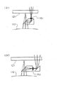
固定マークは、例えば図3の(a)、(b)に例示するような構造を有する。
(a)に示す固定マークは、投影光学系112を介してプレートステージ側から進行して来た光をプリズムにより先ず投影光学系112の光軸に直角な方向に全反射させて横に振り、さらに同プリズム内で再び全反射させて前記光軸に平行な方向、かつレチクル121の方向に向ける。その方向のプリズムの出射面にマーク151が形成されている。このマーク151は、基準マーク141と共役な位置にくるように配置されている。したがって露光光を用いれば、基準マーク141は投影光学系112を介して固定マーク151の上に重なって結像される。
【0043】
更に、固定マーク151を通過した光は、図4に示されるようなレチクル121、122、123、124のパターンを避けた周辺部に形成された窓121c、121dを通過し、更に前記照明光学系の一部を介して、光電変換素子105(図2参照)にて受光される。ここで、基準マーク141のパターンと固定マーク151のパターンは、例えば、図5(a)に示されているようなスリットマークである。ここで基準マークは、円形の視野中のスリット、固定マークは正方形の視野中の、基準マークと同一形状のスリットとして示されている。プレートステージ201を走査することにより、両スリットが重なり再び離れる際の受光素子105にて検出される信号は、図5の(b)に示されるような左右対称の山型の信号になる。この山型の信号のある高さで水平に切ったスライスレベルによる中点の検出等を行うことにより、干渉計203にてステージの位置座標を計測することができる。
【0044】
このように固定マーク151、152の基準マーク141、142を用いた計測を行う。ここで、固定マークを2つ設けているのは、2つの固定マークを投影光学系112の光軸対称に配置することにより、投影光学系112の光軸の位置を固定点と考えられるようにしたためであり、固定マークは、1つであっても構わない。
【0045】
更に、本実施の形態では、固定マーク152、151を2つの独立した部材で構成したが、例えば図13に示すように、1つの正方形の環状部材150に2つの固定マーク156、157を配置し、その部材150にて2つの固定マーク156、157の間の距離が変化しないようにしてもよい。
【0046】
次に、基準マーク141を用いて、プレートアライメント系131、132の位置を計測する。さらに基準マーク142でプレートアライメント系131、132のいずれか一方を計測することにより、基準マーク142の基準マーク141に対する相対位置が計測される。このようにして基準マーク141との相対的関係が把握された基準マーク142を用いて、プレートアライメント系133、134(図1においてアライメント系134は投影光学系112に隠れている)の位置を計測する。この計測は、通常プレートのアライメントを行うマークと同様のマークを基準マーク141、142に配置しておけば、例えば、画像処理、レーザ光による回折光検出等の通常の信号処理を行うことにより、プレートアライメント系の位置を計測することができる。
【0047】
続いて、まずレチクル121をレチクルを載置するレチクルステージ上に載置し、レチクルアライメントマーク121e、121fをレチクルアライメント系を用いてレチクルアライメント系基準でレチクル121の位置合わせを行う。レチクルアライメント系の基準は、不図示ではあるが、例えばレチクルアライメント系内に設けられた指標板を基準として用いられている。
【0048】
次に、レチクルマーク121a、121bの位置を基準マーク141と、上述した固定マーク151と基準マーク141の検出系を用いて複数点検出する。ここで、レチクルマーク121a、121bは、実パターン近傍に配置されたマークであり、実パターン近傍に配置してあるのは、レチクル描画誤差も実パターンとレチクルマークでほぼ同様となるようにし、描画誤差をも計測、補正するためである。
【0049】
このレチクルマークを複数点検出することにより、レチクルアライメント系を基準にとったときのレチクルマークの投影光学系を介したステージ座標系での位置が基準マークを用いて計測される。以上より、レチクル121を用いたときのベースラインが求まることとなる。
【0050】
次に、レチクル121をレチクル122と交換し、まず、固定マーク151の位置を基準マーク141を用いて検出し、更に、固定マーク152の位置を基準マーク141を用いて検出することにより、先に基準マーク141を用いて計測された、固定マーク151、152の位置との差が、求まり、この差分が基準マーク141のドリフト量として計測されることとなる。この差分がゼロとなるようにオフセット制御すれば、良いことになる。
【0051】
続いてレチクル122の複数のレチクルマークを基準マーク141を用いて計測する。このときレチクルアライメントマークを用いてレチクルアライメント系を基準にとった位置にてレチクル122はセットされ、複数のレチクルマーク計測により、レチクル121とレチクル122のずれを求めることができる。このずれ分をレチクルアライメント系にオフセットとして加え、制御することによりレチクル121とレチクル122の実パターンが同じ関係になるように配置される。レチクル122をレチクル123と交換し、同様のことを行えば、はじめに計測した固定マーク151、152の位置との差を求めることができる。以下レチクル124でも同様である。
【0052】
こうして、得られた各レチクルに対応したドリフト量を表したのが、図6のグラフである。横軸は時間であるが、固定マーク、各レチクルマーク、プレートアライメント系を計測している時間に対応するところに、S1〜S5、R11〜R42、P1〜P2を記してある(P3、P4も適宜固定マーク計測の間に計測するが、図6では不図示)。このようなデータにより、各計測点でのドリフト量を例えば直線近似、2次近似等の補間により求めることも可能であり、ドリフトに適した補間方法を行えば、基準マーク141、142にドリフトが生じてもごく小さな影響のみにとどめることが可能となる。更に、固定マーク151、152等での計測の間隔を短くすれば、より正確なオフセット量を求めることができる。
【0053】
なお、信号補正系は、例えば図2の光電変換素子105からの位置信号と図1のプレート干渉計からの出力信号を受信して、図6のグラフに示すような補間による補正を行う不図示の制御系である。
【0054】
図7、図8は、本発明の第2の実施の形態を示す。この実施の形態では、固定マーク151、152と基準マーク141、142、レチクルマーク121a、121b(図4)と基準マーク141、142、を検出する系の構成として、照明光学系100内のメイン照明光を用いていることが特徴である。
【0055】
図7は、照明光学系100のメイン照明光にて、固定マーク151、152を照明し、固定マーク151、152の投影光学系112による光学像と基準マーク141、142を通過する光を光電変換素子161に光ファイバー304にて導く構成である。光電変換素子161は、プレートステージ201中でも構わないが、本実施の形態では、受光素子161自身の発熱による熱膨張を小さくするために、熱の影響を受けない場所に光ファイバー304にて導くこととした。受光方式としては、スリット開口を利用する、いわゆるスリットスキャン方式や、パターンのエッヂを利用するナイフエッジ方式等が考えられる。
【0056】
図8は、受光センサ部にステージに埋設されたCCD等の撮像素子162を用い、基準マーク141、142の像を拡大して撮像素子162へ導く拡大光学系171を設けている。この場合には、例えば基準マーク141、142に図9(a)に示すような正方形の環状枠、固定マーク151、152、レチクルマーク121a、121bに図9(b)に示すような十文字の各枝が3本の線(各線の太さは(a)の枠の幅とほぼ同一で、十文字の枝の全長は(a)の枠の一辺の長さより長い)で形成されたような上下、左右対称のマークを配置すれば、撮像素子162に映し出される合成像は、図9(c)のように、両者を重ね合わせた像になる。
【0057】
この像を図10(a)の点線に示されている領域、即ち3本の十文字の線と正方形の環状枠とに挟まれた、図9(b)の十文字の枝の全長をカバーする領域にて画像処理を行うことにより、基準マーク141、142と固定マーク151、152、または基準マーク141、142とレチクルマーク121a、121bの相対位置を検出することが可能となる。図10(a)、(b)は、画像処理したときの長さ方向と信号レベルの関係を示している。基準マーク、固定マーク、レチクルマークの各線に対応する信号レベルの急変する箇所の間隔を調べれば、各マークの相対的関係が検出できる。
【0058】
また、メイン照明光を用いる場合には、照射による熱膨張を避ける為、レチクルブラインド109(図1)により、各計測ポイントの領域に照射エリアを絞ることが望ましい。
【0059】
図11は、先の第2の実施の形態の変形例であり、固定マーク153等と基準マーク141、142の相対位置検出系とレチクルマーク121a、121bと基準マーク141、142の相対位置検出系で基準マーク141等を照明する照明部分と投影光学系112を介するところまでが共通であり、受光部163、164を別に配置した例である。この場合には、レチクル121に窓等をあけるような工夫をする必要がなくなる。図11では、固定マーク153の後方に受光センサ163を設けているが、熱的な影響等が大きい場合には、光ファイバー(図示せず)により受光光を伝達することも可能である。
【0060】
図12は、図11同様に、先の第2の実施の形態の変形例であり、図11とは異なり、固定マーク153等と基準マーク141等の相対位置検出系と、レチクルマーク121a、121bと基準マーク141等の相対位置検出系で、固定マーク153等を照明する照明部とレチクルマークを照明する照明部が異なり、固定マーク153等の方は、独立照明系181を有し、レチクルマーク121a、121bの方は、メイン照明光学系100を用いる構成とした。このように配置構成することにより、メイン照明光学系100で固定マーク153等まで照明する図7、図8の構成に対して、照明エリア増加に伴う照度低下を防ぐことができる。また、この構成にて図8のように、受光系164に撮像素子を用いることも当然可能である。
【0061】
ステージの大型化を避けるために、複数個の基準マークを設けた場合には、各基準マーク間の位置計測に対しても、動的なレチクルを用いることなく、装置固有の固定マークを用いることによって、レチクルアライメント系の計測に依らず、投影光学系を介したステージ座標系の位置を正確に計測することが可能になる。加えて、例えば固定マークに対する変動をモニタできるため、リミット値を設けることにより、上下動する基準マークの駆動部の不良を容易に発見できるメリットもある。更には、本発明による装置は固定マークを加えることにより製造可能であり、コスト的な問題は生じない。
【0062】
また本発明は、基準マークのドリフトに限らず例えば投影光学系のドリフトにも対処できる。
【0063】
さらに、例えば基準マークのドリフト量が安定したところで、2カ所に配置された固定マークを基準マークを用いて計測することにより、投影光学系の倍率のキャリブレーションに用いることもできる。
【0064】
さらには、固定マークと基準マークとの計測系を用いて、プレートステージの上下動による信号強度の変化を計測し、投影光学系のピント位置を求め、斜入射型のオートフォーカス系の較正を行うことも可能になる。
【0065】
【発明の効果】
以上のように本発明によれば、固定マークは交換されるレチクルとは別のマークとして装置に固定されているので、たとえ基準マークが上下動できる構造のためにドリフトしたとしても、相対的な位置関係の計測に実質的に影響を与えない構成をとることが可能になる。
【図面の簡単な説明】
【図1】本発明による装置の概略を示す斜視図である。
【図2】本発明の第1の実施の形態の概略構成図である。
【図3】本発明に用いる固定マークの例を、レチクルと投影光学系の一部と共に示す図である。
【図4】本発明に用いるレチクルの窓を示す図である。
【図5】本発明に用いる基準マークのパターンと固定マークのパターンの例及びそれらを走査したときに受光素子で検出される信号の例を示す図である。
【図6】各レチクルに対応するドリフト量を表すグラフを示す線図である。
【図7】本発明の第2の実施の形態の概略構成図である。
【図8】図7の実施の形態の変形例であり、拡大光学系を含む例を示す図である。
【図9】本発明に用いる基準マーク、固定マーク、レチクルマークのパターンの例及びそれらを重ね合わせた合成像を示す図である。
【図10】図9に示すパターンの合成像とそれを画像処理した場合の説明図である。
【図11】図7に示す実施の形態の別の変形例であり、固定マークとレチクルマークの受光部を別に配置した例を示す図である。
【図12】図7に示す実施の形態のさらに別の変形例であり、固定マークが独立の照明系を有する場合の例を示す図である。
【図13】本発明に用いる固定マークを一体の枠上に形成した例を、投影光学系の一部と共に示す図である。
【符号の説明】
100 照明光学系
105、161〜154 受光素子
112 投影光学系
121、122、123、124 レチクル
131、132、133、134 プレートアライメント系
141、142 基準マーク
151、152 固定マーク
201 プレートステージ
202 基板
211 レチクルアライメント系
301 シャッター
303 光ファイバー[0001]
BACKGROUND OF THE INVENTION
The present invention relates to a projection exposure apparatus for a substrate, and more particularly to a projection exposure apparatus for a substrate having a reference mark in a stage coordinate system and used for manufacturing a large liquid crystal panel or the like.
[0002]
[Prior art]
A reference position of an exposure apparatus such as a large liquid crystal panel is determined by a reference mark placed on the substrate stage, and is collated with a reticle, that is, an original alignment mark through the projection optical system, and the projection optical system in the stage coordinate system. The position of the reticle via is determined.
[0003]
Further, the exposure apparatus has a plate alignment system, and when exposing the second layer or more on the plate, that is, the photosensitive substrate, a reference mark is used to detect the position of the plate exposed on the first layer. Then, the position of the plate alignment system is detected.
[0004]
In this way, the baseline of the plate alignment system in the so-called exposure apparatus is obtained. The baseline is a type of vector display with respect to the reference position of the projection optical system, in which the position of the object or the system of the object is displayed in the coordinates of the stage coordinate system.
[0005]
In general, the plate alignment mark on the plate carried on the substrate stage is observed with the plate alignment system through the above steps before exposure, the position is measured, and the plate is aligned using the above baseline value. The exposure for the second and subsequent layers is started. However, in a particularly large and square substrate exposure apparatus, a reference mark that moves up and down is provided at the position of the substrate stage on which the plate is placed, and the base mark is raised upward when the plate is not placed. The line is measured, and when it is placed, it is retracted downward. With this structure, it is possible to avoid an increase in the size of the stage, reduce costs, and increase accuracy.
[0006]
In particular, in an exposure apparatus such as a liquid crystal panel that forms one screen with a plurality of reticles, the position of the plurality of reticles is measured using a reference mark that is raised for each reticle while exchanging the reticles. The position of the plate alignment system and the position of each reticle described above are detected by the stage coordinate system, and a so-called baseline for each reticle is obtained.
[0007]
A method for detecting the position of each reticle is, for example, a reticle for position detection on a reticle using a reference mark provided on a stage and a light receiving sensor provided below the reference mark as disclosed in JP-A-61-143760. The relative position with respect to the mark is detected, or the slit mark on the reference mark is emitted from the stage side as in JP-A-63-284814, and the relative position with respect to the slit mark on the reticle is determined via the projection optical system. There is a method of detecting by a light receiving sensor in the illumination optical system.
[0008]
[Problems to be solved by the invention]
However, in the above conventional technique, for example, when four reticles are used, it takes time to replace the reticle and time to detect the position of the plate alignment system. Takes time. In addition, recently, due to device optimization, panel enlargement, and the like, the number of reticles is usually four, but six are required, and more and more. Therefore, when the position of the reticle mark, the plate alignment system, etc. is detected by raising the reference mark, the time for measuring the position of each reticle and the position of the plate alignment system becomes considerably long, and the reference mark itself moves up and down. Because it is a mechanism, force is applied due to movement of the stage, etc., or due to thermal factors due to movement of the stage etc., the reference mark itself drifts, and the measured value changes over time Has caused problems.
[0009]
In this type of exposure apparatus, a plate alignment mark is arranged at a terminal portion located at the end of the substrate, and a plurality of so-called off-axis plate alignments are generally provided near the position of the alignment mark in order to further increase the throughput of the exposure apparatus. A configuration having a system is taken. For example, when alignment marks are provided at the four corners of the substrate, alignment can be completed without moving the stage by setting the distance between the four plate alignment systems with the same dimensions as the alignment marks. Which is advantageous for the throughput of the apparatus. In this case, the stage stroke is determined when the reference mark is moved with respect to the position of each plate alignment system. In this case, the stage stroke can be reduced by arranging two or more reference marks on the stage. Conventionally, when the positions (intervals) of these two reference marks are measured, they are detected using the same mark on one reticle. This reticle is rotated by a value measured by a so-called yawing interferometer that measures the amount of rotation of the stage so as to correct the influence of yawing caused by the movement of the stage, and the rotation is performed by an independent reticle alignment system. And is controlled by the reticle alignment system. In recent years, control may be performed by a reticle interferometer that measures the position on the reticle stage. In such a case, measurement of two reference marks causes a measurement error and a control error when the reticle is aligned.
[0010]
As described above, an object of the present invention is to neglect or minimize the influence of a so-called drift amount, which is a change in a reference mark that can occur over time when measuring a baseline in a plurality of reticles.
[0011]
[Means for Solving the Problems]
In order to achieve the above object, a projection exposure apparatus according to a first aspect of the present invention includes an
[0012]
With this configuration, since the fixed mark, the third position detection system, and the signal correction system are provided, the measurement error due to the drift of the reference mark is corrected.
[0013]
According to a second aspect of the present invention, there is provided a projection exposure apparatus according to the first aspect of the present invention, further comprising: an original plate exchanging apparatus that sequentially sets a plurality of the original plates on the object plane of the projection optical system; Is based on a plurality of pieces of information relating to the relative positions of the reference mark and the fixed mark obtained by the third position detection system each time the plurality of original plates are sequentially set via the original plate exchanging apparatus. A correction amount is calculated, and the second reference mark output signal obtained for each original in the second position detection system based on the correction amount and the first position detection system obtained by the first position detection system. It is characterized in that at least one of the one reference mark output signal is corrected.
[0014]
In the present invention, as shown in the graph of FIG. 6, the signal correction system is obtained for each original plate based on the correction amount calculated based on a plurality of pieces of information obtained by the third position detection system. Since the second reference mark output signal or the first reference mark output signal is corrected, the measurement error due to the drift of the reference mark is further finely corrected. That is, by performing calibration using a fixed mark for each reticle as an original, the effect of drift when measuring the baseline with a plurality of reticles is the same as that for a single reticle, and the fixed mark. Only the very short period between the measurement of the reference mark and the last measurement measured with the reticle will be affected. Further, the value obtained by measuring the position of the fixed mark can be interpolated, and a more detailed drift amount can be estimated and corrected.
[0015]
Further, as in the projection exposure apparatus according to the third aspect of the present invention, the reference mark may be configured to be retracted from the image plane of the projection optical system and stored in the substrate stage (see FIG. 1). ).
[0016]
With this configuration, since the reference mark can be provided at the position of the substrate stage on which the substrate is to be placed, the increase in the size of the stage and the increase in the size of the entire apparatus can be avoided.
[0017]
As shown in FIG. 2 or FIG. 11, the projection exposure apparatus according to the fourth aspect of the invention includes the third position detection system in addition to the apparatus of the first to third aspects. The reference mark illumination system shared with the system; the reference mark illumination system has an exposure wavelength when the relative position between the reference mark and the original plate is detected by the second position detection system. An original mark formed on the original plate by light is illuminated through the projection optical system; when the relative position between the reference mark and the fixed mark is detected by the third position detection system, exposure is performed. The fixed mark is illuminated with light having a wavelength via the projection optical system.
[0018]
In the projection exposure apparatus according to the fifth aspect of the present invention, as shown in FIG. 2, the third position detection system is shared with the second position detection system as compared with the fourth aspect of the present invention. A
[0019]
If comprised as mentioned above, since a reference mark is observed via a projection optical system, drift including a projection optical system can be corrected.
[0020]
In the projection exposure apparatus according to the sixth aspect of the present invention, as shown in FIG. 7 or FIG. 8, the exposure illumination system includes an original mark formed on the original and the reference optical system via the projection optical system. And illuminating the fixed mark and the reference mark via the projection optical system; the third position detection system includes a photoelectric detector shared with the second position detection system. And the photoelectric detector detects the relative position between the reference mark and the original plate by the second position detection system, and the original plate formed on the reference mark via the projection optical system. Receiving light from the image of the mark and the reference mark; when detecting the relative position of the reference mark and the fixed mark by the third position detection system, the projection optical system passes through the projection optical system. The fixed matrix formed on the substrate mark Characterized by receiving the light from the image and the reference mark of click.
[0021]
With the configuration described above, since the original mark and the fixed mark are observed through the projection optical system, drift including the projection optical system can be corrected.
[0022]
In the projection exposure apparatus according to the seventh aspect of the present invention, as shown in FIG. 12, the exposure illumination system illuminates the original mark formed on the original and the reference mark via the projection optical system. The third position detection system includes a fixed mark illumination system that illuminates the fixed mark and the reference mark via the projection optical system; and the third position detection system includes the second position detection system. A photoelectric detector shared with a position detection system, and the photoelectric detector uses the projection optical system to detect the relative position between the reference mark and the original plate in the second position detection system. Receiving light from the original mark image formed on the reference mark and the reference mark; and detecting a relative position between the reference mark and the fixed mark by the third position detection system. Includes a substrate mask through the projection optical system. Characterized by receiving the light from the image and the reference mark of the fixing marks are formed on the click.
[0023]
If comprised in this way, since it has a fixed mark illumination system, the fall of the illumination intensity accompanying the increase in an illumination area can be prevented.
[0024]
In the projection exposure apparatus according to the eighth aspect of the present invention, as shown in FIGS. 7, 8, and 12, the third position detection system is arranged between the reference mark and the photoelectric detector. It has a light guide member shared with the two-position detection system.
[0025]
If comprised in this way, the influence of the heat_generation | fever of a photoelectric detection element can be reduced.
[0026]
In the projection exposure apparatus according to the ninth aspect of the present invention, as shown in FIG. 8, the light guide member is formed on the substrate mark via the projection optical system. An enlarged optical system is provided that forms enlarged images of the fixed mark image and the reference mark on the light receiving surface of the photoelectric detector.
[0027]
If comprised in this way, since an expansion optical system is provided, the detection accuracy of the image of a mark becomes high.
[0028]
In a method for manufacturing a liquid crystal display device according to a tenth aspect of the present invention, a pattern on the original plate is transferred via the projection optical system using the projection exposure apparatus according to any one of the first to ninth aspects. Exposing the photosensitive substrate.
[0029]
With such a configuration, a plurality of reticles are used particularly when manufacturing a large-sized liquid crystal display device. However, when a baseline is measured in each reticle, a change in reference mark with time, that is, a so-called drift amount is generated. However, since the drift amount can be ignored or the influence can be minimized, a high-quality liquid crystal display device can be manufactured.
[0030]
DETAILED DESCRIPTION OF THE INVENTION
Embodiments of the present invention will be described below with reference to the drawings. In addition, in each figure, the same code | symbol is attached | subjected to the mutually same or equivalent member, and the overlapping description is abbreviate | omitted.
[0031]
FIG. 1 is a schematic block diagram of an exposure apparatus according to the present invention. In this embodiment, a
[0032]
The
[0033]
Further, an original stage (not shown) on which the
[0034]
Between the position where the reticle is to be placed and the projection
[0035]
Further, around the projection
[0036]
A
[0037]
The
[0038]
In addition, an
[0039]
In this apparatus, when the pattern on the
[0040]
When measuring the baseline in the exposure apparatus, first, the
[0041]
Next, the positions of the fixed
[0042]
The fixed mark has a structure as illustrated in FIGS. 3A and 3B, for example.
The fixed mark shown in (a) is the light that has traveled from the plate stage side via the projection
[0043]
Furthermore, the light that has passed through the fixed
[0044]
In this way, measurement is performed using the reference marks 141 and 142 of the fixed
[0045]
Further, in the present embodiment, the fixed
[0046]
Next, the positions of the
[0047]
Subsequently, the
[0048]
Next, the positions of the reticle marks 121a and 121b are detected at a plurality of points using the
[0049]
By detecting a plurality of reticle marks, the position of the reticle mark on the stage coordinate system via the projection optical system when the reticle alignment system is taken as a reference is measured using the reference mark. From the above, the baseline when the
[0050]
Next, the
[0051]
Subsequently, a plurality of reticle marks on the
[0052]
FIG. 6 is a graph showing the drift amount corresponding to each reticle thus obtained. The horizontal axis represents time, but S1 to S5, R11 to R42, and P1 to P2 are written in the positions corresponding to the measurement time of the fixed mark, each reticle mark, and the plate alignment system (also P3 and P4) It is measured during the fixed mark measurement as appropriate, but not shown in FIG. 6). With such data, the drift amount at each measurement point can also be obtained by interpolation such as linear approximation and quadratic approximation. If an interpolation method suitable for drift is performed, the reference marks 141 and 142 have drift. Even if it occurs, it is possible to limit only a very small influence. Furthermore, if the measurement interval at the
[0053]
The signal correction system receives, for example, the position signal from the
[0054]
7 and 8 show a second embodiment of the present invention. In this embodiment, the main illumination in the illumination
[0055]
7 illuminates the fixed
[0056]
In FIG. 8, an enlargement
[0057]
The area indicated by the dotted line in FIG. 10 (a), that is, the area covering the entire length of the cross in FIG. 9 (b) sandwiched between three cross-shaped lines and a square annular frame. It is possible to detect the relative positions of the reference marks 141 and 142 and the
[0058]
When main illumination light is used, it is desirable to limit the irradiation area to the area of each measurement point with the reticle blind 109 (FIG. 1) in order to avoid thermal expansion due to irradiation.
[0059]
FIG. 11 shows a modification of the second embodiment, and a relative position detection system for the
[0060]
FIG. 12, like FIG. 11, is a modification of the second embodiment. Unlike FIG. 11, the relative position detection system such as the
[0061]
When multiple reference marks are provided in order to avoid an increase in the size of the stage, a fixed mark unique to the device should be used for position measurement between the reference marks without using a dynamic reticle. Thus, it is possible to accurately measure the position of the stage coordinate system via the projection optical system, regardless of the measurement of the reticle alignment system. In addition, for example, since fluctuations with respect to the fixed mark can be monitored, there is an advantage that a defect in the drive unit of the reference mark moving up and down can be easily found by providing a limit value. Furthermore, the device according to the invention can be manufactured by adding a fixed mark, so that no cost problems arise.
[0062]
Further, the present invention can cope with not only the drift of the reference mark but also the drift of the projection optical system, for example.
[0063]
Furthermore, for example, when the drift amount of the reference mark is stabilized, the fixed marks arranged at two positions are measured using the reference mark, and can be used for calibration of the magnification of the projection optical system.
[0064]
Furthermore, using the measurement system for fixed marks and reference marks, the change in signal intensity due to the vertical movement of the plate stage is measured, the focus position of the projection optical system is obtained, and the oblique incidence type autofocus system is calibrated. It becomes possible.
[0065]
【The invention's effect】
As described above, according to the present invention, since the fixed mark is fixed to the apparatus as a mark different from the reticle to be exchanged, even if the reference mark drifts due to the structure that can move up and down, It is possible to adopt a configuration that does not substantially affect the measurement of the positional relationship.
[Brief description of the drawings]
FIG. 1 is a perspective view schematically showing an apparatus according to the present invention.
FIG. 2 is a schematic configuration diagram of a first embodiment of the present invention.
FIG. 3 is a diagram showing an example of a fixed mark used in the present invention together with a reticle and a part of a projection optical system.
FIG. 4 is a view showing a reticle window used in the present invention;
FIG. 5 is a diagram illustrating an example of a reference mark pattern and a fixed mark pattern used in the present invention, and an example of a signal detected by a light receiving element when they are scanned.
FIG. 6 is a diagram showing a graph representing a drift amount corresponding to each reticle.
FIG. 7 is a schematic configuration diagram of a second embodiment of the present invention.
8 is a diagram showing an example including a magnifying optical system, which is a modification of the embodiment of FIG.
FIG. 9 is a diagram showing examples of patterns of reference marks, fixed marks, and reticle marks used in the present invention, and a composite image obtained by superimposing them.
FIG. 10 is an explanatory diagram when the combined image of the pattern shown in FIG. 9 and image processing thereof are performed.
11 is a diagram showing another modification of the embodiment shown in FIG. 7, in which a fixed mark and a reticle mark light receiving portion are separately arranged.
12 is a diagram showing still another modified example of the embodiment shown in FIG. 7 and showing an example in which a fixed mark has an independent illumination system. FIG.
FIG. 13 is a diagram showing an example in which a fixed mark used in the present invention is formed on an integral frame together with a part of a projection optical system.
[Explanation of symbols]
100 Illumination optical system
105, 161-154 Light receiving element
112 Projection optical system
121, 122, 123, 124 reticle
131, 132, 133, 134 Plate alignment system
141, 142 fiducial mark
151, 152 Fixed mark
201 Plate stage
202 substrate
211 Reticle alignment system
301 Shutter
303 optical fiber
Claims (10)
前記感光性基板を載置すると共に前記投影光学系の像面に沿って移動する基板ステージと;
前記基板ステージに設けられた基準マークと;
前記感光性基板の位置を検出すると共に前記基準マークに対する位置を検出する第1の位置検出系と;
前記基準マークと前記原版との相対位置を検出する第2の位置検出系と;
パターンの投影のために前記原版が載置される位置と前記投影光学系との間に固設された固定マークと;
前記基準マークと前記固定マークとの相対位置を検出する第3の位置検出系と;
前記第3の位置検出系にて得られる前記基準マークと前記固定マークとの相対位置に関する情報に基づいて、前記第1の位置検出系から出力される基準マークと感光性基板との相対位置に関する第1の基準マーク検出信号と、前記第2の位置検出系から出力される前記基準マークと前記原版との相対位置に関する第2の基準マーク検出信号との少なくとも一方を補正する信号補正系と;
を備えたことを特徴とする投影露光装置。An exposure illumination system that illuminates the original on which the predetermined pattern is formed with exposure light, and a projection optical system that forms a pattern image on the original that is illuminated by the exposure illumination system on a photosensitive substrate, In a projection exposure apparatus that exposes a pattern on the original onto the photosensitive substrate;
A substrate stage for mounting the photosensitive substrate and moving along the image plane of the projection optical system;
A reference mark provided on the substrate stage;
A first position detection system for detecting a position of the photosensitive substrate and detecting a position relative to the reference mark;
A second position detection system for detecting a relative position between the reference mark and the original plate;
A fixed mark fixed between a position where the original is placed for pattern projection and the projection optical system;
A third position detection system for detecting a relative position between the reference mark and the fixed mark;
The relative position between the reference mark output from the first position detection system and the photosensitive substrate based on the information regarding the relative position between the reference mark and the fixed mark obtained by the third position detection system. A signal correction system for correcting at least one of a first reference mark detection signal and a second reference mark detection signal related to a relative position between the reference mark and the original plate output from the second position detection system;
A projection exposure apparatus comprising:
前記信号補正系は、前記原版交換装置を介して前記複数の原版が順次設定される毎に、前記第3の位置検出系にて得られる前記基準マークと前記固定マークとの相対位置に関する複数の情報に基づいて補正量を算出し、該補正量に基づいて前記第2の位置検出系にて前記各原版毎に得られる前記第2の基準マーク出力信号と前記第1の位置検出系にて得られる前記第1の基準マーク出力信号との少なくとも一方を補正することを特徴とする、請求項1記載の投影露光装置。An original plate exchange device for sequentially setting a plurality of the original plates on the object plane of the projection optical system;
The signal correction system includes a plurality of relative positions of the reference mark and the fixed mark obtained by the third position detection system each time the plurality of originals are sequentially set via the original exchange device. A correction amount is calculated based on the information, and the second reference mark output signal obtained for each original in the second position detection system based on the correction amount and the first position detection system. The projection exposure apparatus according to claim 1, wherein at least one of the obtained first reference mark output signal is corrected.
該基準マーク照明系は、前記第2の位置検出系にて前記基準マークと前記原版との相対位置を検出する際には、露光波長を持つ光によって前記原版上に形成された原版マークを前記投影光学系を介して照明し;
前記第3の位置検出系にて前記基準マークと前記固定マークとの相対位置を検出する際には、露光波長を持つ光によって前記固定マークを前記投影光学系を介して照明することを特徴とする請求項1乃至請求項3のいずれかに記載の投影露光装置。The third position detection system includes the reference mark illumination system shared with the second position detection system;
When the relative position between the reference mark and the original plate is detected by the second position detection system, the reference mark illumination system converts the original mark formed on the original plate with light having an exposure wavelength. Illuminate via projection optics;
When the relative position between the reference mark and the fixed mark is detected by the third position detection system, the fixed mark is illuminated through the projection optical system with light having an exposure wavelength. The projection exposure apparatus according to any one of claims 1 to 3.
前記光電検出器は、前記投影光学系を介して前記固定マーク上に形成される前記基準マークの像と前記固定マークとからの光を、前記露光用照明系の1部を介して受光することを特徴とする請求項4記載の投影露光装置。The third position detection system includes a photoelectric detector provided in the exposure illumination system shared with the second position detection system;
The photoelectric detector receives light from the image of the reference mark formed on the fixed mark and the fixed mark via the projection optical system via a part of the illumination system for exposure. The projection exposure apparatus according to claim 4.
前記第3の位置検出系は、前記第2位置検出系と共用する光電検出器を有し;
前記光電検出器は、前記第2位置検出系にて前記基準マークと前記原版との相対位置を検出する際には、前記投影光学系を介して前記基準マーク上に形成される前記原版マークの像と前記基準マークとからの光を受光し;
前記第3の位置検出系にて前記基準マークと前記固定マークとの相対位置を検出する際には、前記投影光学系を介して前記基板マーク上に形成される前記固定マークの像と前記基準マークとからの光を受光することを特徴とする、請求項1乃至請求項3のいずれかに記載の投影露光装置。The exposure illumination system illuminates the original mark formed on the original, the reference mark via the projection optical system, the fixed mark, and the reference mark via the projection optical system. Illuminate;
The third position detection system has a photoelectric detector shared with the second position detection system;
When the photoelectric detector detects the relative position between the reference mark and the original plate by the second position detection system, the photoelectric detector detects the original mark formed on the reference mark via the projection optical system. Receiving light from the image and the fiducial mark;
When the relative position between the reference mark and the fixed mark is detected by the third position detection system, the image of the fixed mark formed on the substrate mark via the projection optical system and the reference 4. The projection exposure apparatus according to claim 1, wherein the projection exposure apparatus receives light from the mark.
前記第3の位置検出系は、前記固定マークと前記投影光学系を介して前記基準マークとを照明する固定マーク照明系とを有し;
前記第3の位置検出系は、前記第2位置検出系と共用する光電検出器を有し、前記光電検出器は、前記第2位置検出系にて前記基準マークと前記原版との相対位置を検出する際には、前記投影光学系を介して前記基準マーク上に形成される前記原版マークの像と前記基準マークとからの光を受光し;
前記第3の位置検出系にて前記基準マークと前記固定マークとの相対位置を検出する際には、前記投影光学系を介して前記基板マーク上に形成される前記固定マークの像と前記基準マークとからの光を受光することを特徴とする、請求項1ないし請求項3のいずれかに記載の投影露光装置。The exposure illumination system illuminates the original mark formed on the original and the reference mark via the projection optical system;
The third position detection system includes a fixed mark illumination system that illuminates the fixed mark and the reference mark via the projection optical system;
The third position detection system includes a photoelectric detector shared with the second position detection system, and the photoelectric detector determines a relative position between the reference mark and the original plate in the second position detection system. When detecting, light from the image of the original mark formed on the reference mark and the reference mark is received via the projection optical system;
When the relative position between the reference mark and the fixed mark is detected by the third position detection system, the image of the fixed mark formed on the substrate mark via the projection optical system and the reference 4. The projection exposure apparatus according to claim 1, wherein the projection exposure apparatus receives light from the mark.
Priority Applications (4)
| Application Number | Priority Date | Filing Date | Title |
|---|---|---|---|
| JP1764897A JP4029134B2 (en) | 1997-01-17 | 1997-01-17 | Projection exposure equipment |
| TW086117483A TW357396B (en) | 1997-01-17 | 1997-11-22 | Exposure device |
| KR1019980000329A KR19980070407A (en) | 1997-01-17 | 1998-01-09 | Exposure equipment |
| US09/009,365 US5978069A (en) | 1997-01-17 | 1998-01-20 | Exposure apparatus and methods |
Applications Claiming Priority (1)
| Application Number | Priority Date | Filing Date | Title |
|---|---|---|---|
| JP1764897A JP4029134B2 (en) | 1997-01-17 | 1997-01-17 | Projection exposure equipment |
Publications (2)
| Publication Number | Publication Date |
|---|---|
| JPH10208991A JPH10208991A (en) | 1998-08-07 |
| JP4029134B2 true JP4029134B2 (en) | 2008-01-09 |
Family
ID=11949684
Family Applications (1)
| Application Number | Title | Priority Date | Filing Date |
|---|---|---|---|
| JP1764897A Expired - Fee Related JP4029134B2 (en) | 1997-01-17 | 1997-01-17 | Projection exposure equipment |
Country Status (1)
| Country | Link |
|---|---|
| JP (1) | JP4029134B2 (en) |
Families Citing this family (2)
| Publication number | Priority date | Publication date | Assignee | Title |
|---|---|---|---|---|
| JP5681065B2 (en) * | 2011-08-26 | 2015-03-04 | 株式会社大日本科研 | Substrate positioning method |
| JP6116457B2 (en) * | 2013-09-26 | 2017-04-19 | 株式会社Screenホールディングス | Drawing device |
-
1997
- 1997-01-17 JP JP1764897A patent/JP4029134B2/en not_active Expired - Fee Related
Also Published As
| Publication number | Publication date |
|---|---|
| JPH10208991A (en) | 1998-08-07 |
Similar Documents
| Publication | Publication Date | Title |
|---|---|---|
| US5783833A (en) | Method and apparatus for alignment with a substrate, using coma imparting optics | |
| KR970072024A (en) | Projection exposure equipment | |
| CN112639623B (en) | Apparatus and method for measuring position of alignment mark | |
| JPH10294268A (en) | Projection aligner and positioning method | |
| JPS5994032A (en) | Apparatus for measuring characteristics of image forming optical system | |
| US5978069A (en) | Exposure apparatus and methods | |
| JP5137526B2 (en) | Shape measuring apparatus, shape measuring method, and exposure apparatus | |
| US5929978A (en) | Projection exposure apparatus | |
| JP2002231616A (en) | Instrument and method for measuring position aligner and method of exposure, and method of manufacturing device | |
| JPH09219354A (en) | Position sensing apparatus, and aligner with the same | |
| JP3506155B2 (en) | Projection exposure equipment | |
| JP3551570B2 (en) | Scanning exposure apparatus and exposure method | |
| JP3218631B2 (en) | Projection exposure equipment | |
| JP4029134B2 (en) | Projection exposure equipment | |
| JP3369266B2 (en) | Stage position control accuracy measurement method | |
| JP3109107B2 (en) | Position detecting apparatus, exposure apparatus and exposure method | |
| JPH11251218A (en) | Method and device for detecting position and aligner equipped with the same | |
| JPH05118957A (en) | Method for inspecting projecting optical system | |
| JP2005175383A (en) | Aligner, method of alignment and device manufacturing method | |
| JPH06349707A (en) | Alignment method | |
| JP3163669B2 (en) | Detection apparatus, exposure apparatus, and exposure method | |
| JP2934726B2 (en) | Projection exposure method | |
| JPH0754794B2 (en) | Projection type exposure system | |
| JP3031321B2 (en) | Projection exposure apparatus and method | |
| JPH09171956A (en) | Exposure system |
Legal Events
| Date | Code | Title | Description |
|---|---|---|---|
| A621 | Written request for application examination |
Effective date: 20040119 Free format text: JAPANESE INTERMEDIATE CODE: A621 |
|
| A977 | Report on retrieval |
Effective date: 20051125 Free format text: JAPANESE INTERMEDIATE CODE: A971007 |
|
| TRDD | Decision of grant or rejection written | ||
| A01 | Written decision to grant a patent or to grant a registration (utility model) |
Free format text: JAPANESE INTERMEDIATE CODE: A01 Effective date: 20070904 |
|
| A61 | First payment of annual fees (during grant procedure) |
Free format text: JAPANESE INTERMEDIATE CODE: A61 Effective date: 20070917 |
|
| R150 | Certificate of patent (=grant) or registration of utility model |
Free format text: JAPANESE INTERMEDIATE CODE: R150 |
|
| FPAY | Renewal fee payment (prs date is renewal date of database) |
Year of fee payment: 3 Free format text: PAYMENT UNTIL: 20101026 |
|
| FPAY | Renewal fee payment (prs date is renewal date of database) |
Year of fee payment: 3 Free format text: PAYMENT UNTIL: 20101026 |
|
| FPAY | Renewal fee payment (prs date is renewal date of database) |
Free format text: PAYMENT UNTIL: 20131026 Year of fee payment: 6 |
|
| FPAY | Renewal fee payment (prs date is renewal date of database) |
Year of fee payment: 6 Free format text: PAYMENT UNTIL: 20131026 |
|
| S531 | Written request for registration of change of domicile |
Free format text: JAPANESE INTERMEDIATE CODE: R313531 |
|
| FPAY | Renewal fee payment (prs date is renewal date of database) |
Free format text: PAYMENT UNTIL: 20131026 Year of fee payment: 6 |
|
| R350 | Written notification of registration of transfer |
Free format text: JAPANESE INTERMEDIATE CODE: R350 |
|
| FPAY | Renewal fee payment (prs date is renewal date of database) |
Year of fee payment: 6 Free format text: PAYMENT UNTIL: 20131026 |
|
| LAPS | Cancellation because of no payment of annual fees |