JP4023565B2 - Manufacturing method for paper containers - Google Patents
Manufacturing method for paper containers Download PDFInfo
- Publication number
- JP4023565B2 JP4023565B2 JP34418797A JP34418797A JP4023565B2 JP 4023565 B2 JP4023565 B2 JP 4023565B2 JP 34418797 A JP34418797 A JP 34418797A JP 34418797 A JP34418797 A JP 34418797A JP 4023565 B2 JP4023565 B2 JP 4023565B2
- Authority
- JP
- Japan
- Prior art keywords
- container
- flange portion
- paper
- clearance
- paperboard
- Prior art date
- Legal status (The legal status is an assumption and is not a legal conclusion. Google has not performed a legal analysis and makes no representation as to the accuracy of the status listed.)
- Expired - Fee Related
Links
Images


Landscapes
- Making Paper Articles (AREA)
- Containers Having Bodies Formed In One Piece (AREA)
Description
【0001】
【発明の属する技術分野】
本発明は、フランジ部に蓋材を熱接着させて密封するトレイ状の紙製容器の製造方法に関するものである。
【0002】
【従来の技術】
トレー状の紙製容器としては、例えば実公昭61−14437号公報に記載されているように、表面にプラスチックフィルム層を有する厚紙をプレス成形あるいは貼着して構成したものが知られている。この紙製トレイは、従来から量販店等で利用されている肉,魚等を収納する発泡トレイの代わりに使用するものである。他に、特公昭56−48300号公報,実開平6−80615号公報,特開昭63−176130号公報等にもプレス成形による同様の紙製容器が示されており、これらプレス成形により構成する紙製容器の場合、容器材料である板紙ブランクには、成形時にシワになる部分に放射状に溝状の折り罫が設けられている。また、上記実公昭61−14437号公報には、ポリオレフィン混抄紙を材料として成形したトレイがあることも記載されている。そのほか、プレス成形したものでは、使い捨ての紙皿等も従来から知られている。
【0003】
【発明が解決しようとする課題】
上記従来の紙製トレイあるいはポリオレフィン混抄紙等を材料としたトレイは、内容物を入れてストレッチ包装することによりある程度の密封性を得ることができるが、その場合の密封性は損なわれやすく、運搬性にも問題がある。また、上記従来の紙皿を利用してストレッチ包装した場合も同様の問題がある。そこで、表面に熱接着性樹脂層を設けた板紙をプレス成形してトレイ状で上端にフランジ部を有する容器とし、内容物を入れ、フィルム状の蓋材をフランジ部に熱接着させることによって密封することが考えられる。しかしながら、板紙をプレス成形してそのようなトレイ状の容器を形成した場合、従来設備を用い通常の紙成形金型を用いたプレス成形では、その容器は、フランジ部および側面部にできる紙シワのためにフランジ部の平滑性が損なわれ、蓋材を熱接着させた時に隙間ができてシール抜けを生ずるだけでなく、容器自体も、紙シワに起因してフランジ部表面にフランジ部内縁からフランジ部外縁へ連通するトンネル状の連通孔ができやすく、密封性を確保することが難しい。プレス圧を高くすればそのような問題をある程度解決できるが、そのためには大型で高価な設備が必要となる。また、成形温度を高くし材料表面の樹脂の溶融によってフランジ部表面の平滑化を図ることも考えられが、そうすると、成形後の容器の金型からの離型性が損なわれてしまう。
【0004】
したがって、板紙からプレス成形により形成しフランジ部に蓋材を熱接着させるトレイ状の紙製容器の密封性を向上させることが課題である。
【0005】
【課題を解決するための手段】
本発明は、表面に熱接着性樹脂層を有する板紙からプレス成形により形成される上端に蓋材を熱接着させるフランジ部を備えたトレイ状の容器であって、前記フランジ部が、成形時の紙シワにより生ずる該フランジ部表面のフランジ部内縁からフランジ部外縁へのトンネル状連通孔を閉塞した紙製容器を製造するものである。この紙製容器は、成形時の紙シワにより生ずるフランジ部表面のフランジ部内縁からフランジ部外縁へのトンネル状連通孔が閉塞されたものであるため、内容物を収納し蓋材をフランジ部に熱接着させたときの密封性が向上する。
【0006】
すなわち、本発明による紙製容器の製造方法は、表面に熱接着性樹脂層を有する板紙からプレス成形により形成される上端に蓋材を熱接着させるフランジ部を備えたトレイ状の容器の製造方法であって、型締めされた際の雄型と雌型のクリアランスが偏在しフランジ部にあたる部分のクリアランスが容器側面部にあたる部分のクリアランスより小さくて該フランジ部に集中的にプレス圧がかかる設定の成形金型を用いることを特徴とする。この方法によれば、成形金型に容器材料である板紙がセットされ、型締めされた際に、雄型と雌型のクリアランスが偏在しフランジ部のクリアランスが小さくてフランジ部に集中的にプレス圧がかかり、その結果、成形時にできるフランジ部表面の紙シワがつぶれたものとなってフランジ部の平滑性が向上し、蓋材を熱接着させたときの密封性が向上する。一方、容器側面部は、フランジ部に集中的にプレス圧がかかるため、紙シワのつぶれ度合が小さくなるが、保形性には問題を生じない。フランジ部と容器側面部のクリアランス差は、容器形状,容器材料の厚さ等により異なるものとする。
【0007】
本発明の製造方法は、また、容器外面側にあたる雌型の温度を容器内面側の熱接着性樹脂の融点よりも高く設定し、容器内面およびフランジ部の表面にあたる雄型の温度を前記融点よりも低く設定することを特徴とする。その場合、雌型と雄型の温度に差をつけるため必要に応じて加熱または冷却を行ってもよい。上記プレス圧の設定に加えて金型の温度条件をこのように設定することにより、容器材料である板紙の表面の熱接着性樹脂を溶融させて、この溶融した樹脂により、紙シワにより生ずるフランジ部表面のフランジ部内縁からフランジ部外縁へのトンネル状連通孔を閉塞するようにでき、その上で蓋材をフランジ部に熱接着させることによって密封性が一層向上する。また、この場合、熱接着性樹脂にあたることになる雄型の方からは積極的に加熱しないので、成形後の容器の金型からの離型性は損なわれない。
【0008】
容器材料である板紙は、成形時に紙シワが生ずる部位に紙シワを誘発する折り罫を設けたものとするのがよく、そうすることにより成形性が向上する。
【0009】
【発明の実施の形態】
以下、図面に基づいて本発明の実施の形態を説明する。
【0010】
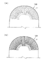
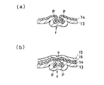
図1は本発明の実施の形態の一例の紙製容器を片側断面で示す正面図、図2の(a)および(b)は板紙ブランクの一例の片側表面図および片側裏面図、図3の(a)および(b)は板紙ブランクの他の例の片側表面図および片側裏面図、図4は成形金型の模式図、図5の(a)および(b)は容器本体および蓋材シール後の状態を図1のA−A断面で示す断面図、図6は図1のB−B線断面図、図7の(a)および(b)は図5の(a)および(b)に対応する比較例の断面図、図8は図6に対応する比較例の断面図である。
【0011】
容器本体1は、長円トレイ状で、図1に示すように底面部2の周縁に湾曲して傾斜状に立ち上がる側面部3を有し、側面部3の上端には、長円環状で略水平なフランジ部4を有する。また、フランジ部4の外周には下方傾斜状に余り部5が延びている。図1において、6は蓋材である。容器本体1には、内容物収納後、図1に二点鎖線で示すように蓋材6がかぶせられ、フランジ部4に熱接着される。
【0012】
上記容器本体1は、例えば図2あるいは図3に示すような長円形状の板紙ブランク10A,10Bからプレス成形によって形成される。板紙ブランク10A,10Bは、プレス成形時に紙シワが生ずる部位に板紙ブランク10A,10Bの表面側(容器内側)から予め所定のパターンで折り罫11が設けられたものである。折り罫11のパターンは容器形状や容器材料の板紙厚等により異ならせる。
【0013】
板紙ブランク10A,10Bの材料は、紙を基材として、表面(容器内面側)に熱可塑性樹脂(熱接着性樹脂)を積層し、裏面(容器外面側)は紙層のままあるいは表面の樹脂よりも融点の高い樹脂を積層したものであり、例えば、ポリプロピレン(PP)/紙、ポリプロピレン(PP)/紙/ポリエステル(PET)等、紙とプラスチックフィルムのラミネート品である。同様にコーティング加工紙でも良い。
【0014】
蓋材6は、ポリエステル(PET)等のプラスチックフィルムであり、イージーピール性を付与するため裏面にピールレジンを積層するのが良い。
【0015】
プレス成形に使用する成形金型20は、図4に示すように、容器内面にあたる内側型部21aとフランジ部4の表面にあたる外側型部21bとに分割された雄型21と、容器外面側にあたる雌型22と、雄型21を支持する固定台23および雌型22を支持する可動台24と、雄型21の側型部21bに対向して可動台24側からスプリング付勢状態で設置されたプレスリング25とからなっている。
【0016】
上記成形金型20は、型締めされプレスリング25により規制された状態で雄型21と雌型22のクリアランスが偏在し、側面部3にあたる部分のクリアランスC1に対しフランジ部4にあたる部分のクリアランスC2が小さくなるよう金型設計される。
【0017】
また、成形温度は、容器外面側にあたる雌型22の温度が、容器内面側の熱接着性樹脂の融点よりも高く、容器内面およびフランジ部4の表面にあたる雄型21の温度が同融点よりも低くなる設定とされる。
【0018】
図2あるいは図3の板紙ブランク10A,10Bを材料とし、上記金型設計の成形金型20を使用して、上記温度条件のもとでプレス成形を行うことにより、図1に示す構成の容器本体1が形成される。
【0019】
その際、容器本体1の側面部3およびフランジ部4には、折り罫11に沿って図1に示すような紙シワfができる。そして、その紙シワfは、成形金型20の型締め時のクリアランス差に起因してフランジ部4に集中的にプレス圧がかかることにより、フランジ部4ではつぶれたものとなり、側面部3ではつぶれ度合の小さいものとなる。
【0020】
図5および図6は、容器本体1が紙13の表面に熱接着性樹脂14を積層したもので、蓋材6がプラスチックフィルム15にピールレジン16を積層したものである場合を示している。この場合、成形された容器本体1のフランジ部4では、図5の(a)に示されるように紙シワfがつぶれ、しかも、熱接着性樹脂14の融点よりも温度の高い雌型22により容器内面側から加熱されて熱接着性樹脂14が溶融し、フランジ部4表面でトンネル状連通孔となる部分を閉塞する。一方、側面部3の紙シワfは、図6に示されるように、つぶれ度合が小さい。それに対し、クリアランス差がなく温度差のない条件でプレス成形した比較例の場合は、図7および図8に示すようにフランジ部4でも側面部3でも同程度に紙シワfがつぶれるが、そのつぶれ度合が比較的小さいために平滑性に欠け、また、フランジ部4表面には図7の(a)に示されるようなトンネル状連通孔pができる。
【0021】
こうして図5の(a)に示されるように紙シワfがつぶれてフランジ部4表面の平滑性が向上するとともに、熱接着性樹脂14によってトンネル状連通孔が閉塞された状態となるため、図5の(b)に示すように、蓋材6はシール温度により溶融した熱接着性樹脂によってフランジ部4に隙間なく熱接着させることができ、また、トンネル状連通孔により密封性が損なわれるのを防止できる。それに対し、上記比較例の場合は、平滑性に欠けるとともに、トンネル状連通孔pができるため、図7の(b)に示すように、シール時に隙間sができてシール抜けが生ずる恐れがあり、また、トンネル状連通孔pが残って密封性が損なわれる恐れがある。
【0022】
この紙製容器は、高い保存性を必要とする食品のマスセール用容器として、また、そのまま食器になる食品のテイクアウト用容器として、また、トイレタリー,日用品等の容器として、また、小型工業製品用等の防湿性を要する容器として、その他、様々な用途の容器として利用できるものである。容器形状や材料はそれぞれの用途に応じて変更可能である。
【0023】
また、プレス成形の金型設計や温度条件も適宜変更することができるものである。
【0024】
【実施例】
容器本体1の材料である板紙ブランク10は、秤量320g/m2の紙の表面に厚さ15μのポリエチレンの接着層を介して厚さ30μのポリプロピレンを積層したものとし、蓋材6は、厚さ12μのポリエステルの裏面にポリエチレンの接着層を介して厚さ30μのピールレジンを積層したものとした。
【0025】
そして、成形金型20は、フランジ部4にあたる部分と側面部3にあたる部分のクリアランス差が約300μ(平均)となる設計とし、成形温度は、雌型が約200℃、雄型が約40〜120℃とした。
【0026】
蓋材6を熱接着させる際のシール条件は、シール温度が200℃、シール時間が2秒×2回、エアー元圧が0.4Mpa、エアーシリンダーボア径が80mmとした。そして、単発式エアーシリンダー駆動シール機を使用し、シールヘッドは2mm巾リングシールとした。
【0027】
成形した容器本体1に浸透性チェック液を入れ、蓋材6を熱接着させた状態で、密封性および浸透性を評価したところ、チェック液の漏れはなく、浸透もなかった。
【0028】
【発明の効果】
本発明によれば、板紙からプレス成形により形成しフランジ部に蓋材を熱接着させるトレイ状の紙製容器の密封性を向上させて従来にない密封性の高い紙製容器を得ることができる。また、製造工程を増やさずに付加価値の高い紙製容器を製造でき、しかも、従来設備を用いて製造できる。また、材料にガスバリアー性の高いものを複合することにより付加価値をより一層高めることができ、蓋材にピール性樹脂を複合することにより容易にイージーピール性を付与できる。
【図面の簡単な説明】
【図1】本発明による紙製容器を片側断面で示す正面図である。
【図2】板紙ブランクの一例の片側表面図(a)およびる片側裏面図(b)である。
【図3】板紙ブランクの他の例の片側表面図(a)および片側裏面図(b)である。
【図4】成形金型の模式図である。
【図5】容器本体および蓋材シール後の状態を図1のA−A断面で示す断面図である。
【図6】図1のB−B線断面図である。
【図7】図5の(a)および(b)に対応する比較例の断面図である。
【図8】図6に対応する比較例の断面図である。
【符号の説明】
1 容器本体
3 側面部
4 フランジ部
6 蓋材
10A,10B 板紙ブランク
11 折り罫
13 紙
14 熱接着性樹脂
20 成形金型
21 雄型
22 雌型
C1 クリアランス(側面部側)
C2 クリアランス(フランジ部側)
f 紙シワ
p トンネル状連通孔
s 隙間[0001]
BACKGROUND OF THE INVENTION
The present invention relates to a method for manufacturing a tray-shaped paper container in which a lid member is thermally bonded to a flange portion and sealed.
[0002]
[Prior art]
As a tray-like paper container, for example, as described in Japanese Utility Model Publication No. 61-14437, a container formed by pressing or sticking cardboard having a plastic film layer on its surface is known. This paper tray is used in place of a foam tray for storing meat, fish, and the like conventionally used in mass retailers. In addition, Japanese Patent Publication No. 56-48300, Japanese Utility Model Laid-Open No. 6-80615, Japanese Patent Laid-Open No. 63-176130, etc. also show similar paper containers formed by press molding. In the case of a paper container, a paperboard blank, which is a container material, is provided with groove-shaped creases radially in the wrinkled portion during molding. In addition, the Japanese Utility Model Publication No. 61-14437 discloses that there is a tray formed from a polyolefin mixed paper as a material. In addition, a disposable paper plate or the like is conventionally known as a press-molded one.
[0003]
[Problems to be solved by the invention]
The above-mentioned conventional paper trays or trays made of polyolefin mixed paper, etc. can obtain a certain level of sealing performance by putting the contents and stretch wrapping. There is also a problem with sex. The same problem occurs when stretch packaging is performed using the conventional paper tray. Therefore, a paperboard with a heat-adhesive resin layer on the surface is press-molded to form a tray-like container with a flange at the top, and the contents are put in. Sealed by thermally bonding a film-like lid to the flange It is possible to do. However, when such a tray-like container is formed by press-molding paperboard, the container is formed into a paper wrinkle that can be formed into a flange part and a side part in press molding using a conventional paper molding die using conventional equipment. As a result, the smoothness of the flange portion is impaired, and when the lid is thermally bonded, a gap is formed and a seal is lost, and the container itself is also formed on the flange surface from the inner edge of the flange portion due to paper wrinkles. A tunnel-like communication hole communicating with the outer edge of the flange portion is easily formed, and it is difficult to ensure sealing performance. Such a problem can be solved to some extent by increasing the press pressure, but this requires a large and expensive facility. In addition, it is conceivable to increase the molding temperature and to smooth the flange surface by melting the resin on the surface of the material. However, if this is done, the releasability of the molded container from the mold will be impaired.
[0004]
Therefore, it is a problem to improve the sealing performance of a tray-like paper container formed by press molding from paperboard and thermally bonding a lid material to the flange portion.
[0005]
[Means for Solving the Problems]
The present invention is a tray-like container having a flange portion for thermally bonding a lid material to an upper end formed by press molding from a paperboard having a heat-adhesive resin layer on the surface, the flange portion at the time of molding A paper container in which a tunnel-like communication hole from the inner edge of the flange portion to the outer edge of the flange portion on the surface of the flange portion caused by paper wrinkles is closed is manufactured . In this paper container, the tunnel-shaped communication hole from the inner edge of the flange portion to the outer edge of the flange portion on the surface of the flange portion caused by paper wrinkles at the time of molding is closed, so the contents are stored and the lid material is used as the flange portion. The sealing performance when thermally bonded is improved.
[0006]
That is , the method for producing a paper container according to the present invention is a method for producing a tray-like container having a flange portion for thermally bonding a lid material to the upper end formed by press molding from a paperboard having a heat-adhesive resin layer on the surface. The clearance between the male mold and the female mold when the mold is clamped is unevenly distributed so that the clearance of the portion corresponding to the flange portion is smaller than the clearance of the portion corresponding to the side surface portion of the container and the pressing pressure is concentrated on the flange portion. It is characterized by using a molding die. According to this method, when the paperboard as the container material is set in the molding die and the mold is clamped, the clearance between the male mold and the female mold is unevenly distributed and the clearance of the flange section is small, so that the flange section is pressed intensively. As a result, paper wrinkles on the surface of the flange portion formed during molding are crushed and the smoothness of the flange portion is improved, and the sealing performance when the lid member is thermally bonded is improved. On the other hand, the side wall of the container is intensively pressed by the flange, so that the degree of crushing of the paper is reduced, but there is no problem in shape retention. The clearance difference between the flange portion and the container side surface portion depends on the container shape, the thickness of the container material, and the like.
[0007]
The manufacturing method of the present invention also sets the temperature of the female mold corresponding to the outer surface of the container to be higher than the melting point of the thermoadhesive resin on the inner surface of the container, and sets the temperature of the male mold corresponding to the inner surface of the container and the surface of the flange portion from the melting point. and setting is also low. In that case, heating or cooling may be performed as necessary to make a difference in temperature between the female mold and the male mold. By setting the temperature condition of the mold in this way in addition to the setting of the press pressure, the heat-adhesive resin on the surface of the paperboard as the container material is melted, and the molten resin causes a flange caused by paper wrinkles. The tunnel-shaped communication hole from the inner edge of the flange portion to the outer edge of the flange portion can be closed, and the sealing performance is further improved by thermally bonding the lid member to the flange portion. Further, in this case, since the male mold that is to be the heat-adhesive resin is not heated positively, the releasability of the molded container from the mold is not impaired.
[0008]
The paperboard that is the container material is preferably provided with a crease that induces paper wrinkles at the site where the paper wrinkles occur during molding, and this improves the moldability.
[0009]
DETAILED DESCRIPTION OF THE INVENTION
Hereinafter, embodiments of the present invention will be described with reference to the drawings.
[0010]
FIG. 1 is a front view showing a paper container as an example of an embodiment of the present invention in one side cross section, and FIGS. 2 (a) and 2 (b) are one side front view and one side back view of an example of a paperboard blank. (A) and (b) is a one-side front view and one-side back view of another example of a paperboard blank, FIG. 4 is a schematic diagram of a molding die, and FIGS. 5 (a) and (b) are container main bodies and lid seals. 1 is a cross-sectional view taken along the line AA of FIG. 1, FIG. 6 is a cross-sectional view taken along line BB of FIG. 1, and FIGS. 7A and 7B are FIGS. FIG. 8 is a cross-sectional view of a comparative example corresponding to FIG. 6.
[0011]
The
[0012]
The said container
[0013]
The
[0014]
The
[0015]
As shown in FIG. 4, the molding die 20 used for press molding corresponds to a
[0016]
In the molding die 20, the clearance between the
[0017]
The molding temperature is such that the temperature of the female mold 22 corresponding to the outer surface of the container is higher than the melting point of the thermoadhesive resin on the inner surface of the container, and the temperature of the
[0018]
By using the
[0019]
At that time, a paper wrinkle f as shown in FIG. 1 is formed along the
[0020]
5 and 6 show a case where the container
[0021]
Thus, as shown in FIG. 5 (a), the paper wrinkle f is crushed to improve the smoothness of the surface of the flange portion 4, and the tunnel-like communication hole is closed by the thermal
[0022]
This paper container is used as a mass-sales container for foods that require high storage stability, as a take-out container for foods that are used as tableware, as a container for toiletries and daily necessities, and for small industrial products. It can be used as a container for various purposes as a container requiring moisture resistance such as the above. The container shape and material can be changed according to each application.
[0023]
Moreover, the die design and temperature conditions of press molding can be changed as appropriate.
[0024]
【Example】
The paperboard blank 10 which is the material of the
[0025]
The molding die 20 is designed so that the clearance difference between the portion corresponding to the flange portion 4 and the portion corresponding to the
[0026]
The sealing conditions for thermally bonding the
[0027]
When the permeable check solution was put into the molded
[0028]
【The invention's effect】
According to the present invention, an unprecedented highly sealed paper container can be obtained by improving the sealing performance of a tray-shaped paper container formed by press molding from paperboard and thermally bonding a lid to the flange portion. . In addition, a high value-added paper container can be manufactured without increasing the number of manufacturing steps, and it can be manufactured using conventional equipment. Further, by adding a material having a high gas barrier property to the material, the added value can be further increased, and an easy peel property can be easily imparted by combining a peelable resin with the cover material.
[Brief description of the drawings]
FIG. 1 is a front view showing a paper container according to the present invention in a cross section on one side.
FIG. 2 is a one-side surface view (a) and a one-side back view (b) of an example of a paperboard blank.
FIG. 3 is a one-side front view (a) and a one-side back view (b) of another example of a paperboard blank.
FIG. 4 is a schematic view of a molding die.
FIG. 5 is a cross-sectional view showing a state after sealing the container body and the lid material, taken along the line AA in FIG. 1;
6 is a cross-sectional view taken along line BB in FIG.
7 is a cross-sectional view of a comparative example corresponding to (a) and (b) of FIG.
8 is a cross-sectional view of a comparative example corresponding to FIG.
[Explanation of symbols]
1
C 2 clearance (flange side)
f Paper wrinkle p Tunnel-shaped communication hole s Clearance
Claims (2)
Priority Applications (1)
| Application Number | Priority Date | Filing Date | Title |
|---|---|---|---|
| JP34418797A JP4023565B2 (en) | 1997-11-28 | 1997-11-28 | Manufacturing method for paper containers |
Applications Claiming Priority (1)
| Application Number | Priority Date | Filing Date | Title |
|---|---|---|---|
| JP34418797A JP4023565B2 (en) | 1997-11-28 | 1997-11-28 | Manufacturing method for paper containers |
Publications (2)
| Publication Number | Publication Date |
|---|---|
| JPH11165725A JPH11165725A (en) | 1999-06-22 |
| JP4023565B2 true JP4023565B2 (en) | 2007-12-19 |
Family
ID=18367310
Family Applications (1)
| Application Number | Title | Priority Date | Filing Date |
|---|---|---|---|
| JP34418797A Expired - Fee Related JP4023565B2 (en) | 1997-11-28 | 1997-11-28 | Manufacturing method for paper containers |
Country Status (1)
| Country | Link |
|---|---|
| JP (1) | JP4023565B2 (en) |
Families Citing this family (5)
| Publication number | Priority date | Publication date | Assignee | Title |
|---|---|---|---|---|
| JP4580505B2 (en) * | 2000-05-19 | 2010-11-17 | 大日本印刷株式会社 | Method for producing sealed paper tray container |
| JP4580504B2 (en) * | 2000-05-19 | 2010-11-17 | 大日本印刷株式会社 | Method for producing sealed paper tray container |
| JP2002225156A (en) * | 2001-01-30 | 2002-08-14 | Toppan Printing Co Ltd | Method for producing paper container and paper container produced by this method |
| FI117933B (en) | 2005-09-29 | 2007-04-30 | Stora Enso Oyj | Process for making cardboard mold, molding and form produced by the manufacture |
| JP5372693B2 (en) * | 2009-10-13 | 2013-12-18 | 東罐興業株式会社 | Container and container manufacturing method |
-
1997
- 1997-11-28 JP JP34418797A patent/JP4023565B2/en not_active Expired - Fee Related
Also Published As
| Publication number | Publication date |
|---|---|
| JPH11165725A (en) | 1999-06-22 |
Similar Documents
| Publication | Publication Date | Title |
|---|---|---|
| US4337116A (en) | Contoured molded pulp container with polyester liner | |
| US7464856B2 (en) | Blank for a disposable thermally insulated container | |
| FI74677C (en) | A packaging container, which is provided with a lid. | |
| US4008347A (en) | Receptacle of foamed plastic lined with unoriented polyolefin film | |
| US4036675A (en) | Film-lined foam plastic receptacles and laminated materials and methods for making the same | |
| WO2015009518A1 (en) | Sealable paperboard container and method for manufacturing the same | |
| JP2006513108A (en) | Containers with rims or other features encapsulated by or molded from injection molding material | |
| CA2440177A1 (en) | Method for producing biodegradable packaging from biaxially drawn film | |
| CA1130245A (en) | Contoured molded pulp container with polyester liner | |
| JPH06135459A (en) | Cup-shaped packing material with plastic cover film | |
| BR112021009150A2 (en) | manufacturing process for producing airtight single-use food containers, such as coffee capsules, which includes a creasing step and an airtight single-use food container manufactured by this process | |
| JP2001328617A (en) | Sealed paper tray container and manufacturing method thereof | |
| JP4023565B2 (en) | Manufacturing method for paper containers | |
| CN113165274A (en) | Method for producing an airtight disposable food container using a sealing head with a specific profile with ribs | |
| JPWO2003101839A1 (en) | Drawing paper container and manufacturing method thereof | |
| JPH10218235A (en) | Composite container and method for producing the same | |
| JP2000033927A (en) | Manufacturing method of deep drawing paper tray | |
| JPS63176130A (en) | Manufacture of deep drawn vessel made of paper | |
| JP4678804B2 (en) | Paper packaging container and molding method and apparatus thereof | |
| JP2004262484A (en) | Manufacturing method of draw-formed paper container | |
| JP2003155018A (en) | Draw-formed paper container | |
| JP2556395B2 (en) | Container manufacturing method | |
| JP2022122638A (en) | Paper tray and its manufacturing method | |
| TW202432436A (en) | Packaging and methods of production thereof | |
| JP4022949B2 (en) | Liquid paper container with drinking mouth |
Legal Events
| Date | Code | Title | Description |
|---|---|---|---|
| A621 | Written request for application examination |
Free format text: JAPANESE INTERMEDIATE CODE: A621 Effective date: 20041122 |
|
| A977 | Report on retrieval |
Free format text: JAPANESE INTERMEDIATE CODE: A971007 Effective date: 20070530 |
|
| A131 | Notification of reasons for refusal |
Free format text: JAPANESE INTERMEDIATE CODE: A131 Effective date: 20070619 |
|
| A521 | Written amendment |
Free format text: JAPANESE INTERMEDIATE CODE: A523 Effective date: 20070814 |
|
| TRDD | Decision of grant or rejection written | ||
| A01 | Written decision to grant a patent or to grant a registration (utility model) |
Free format text: JAPANESE INTERMEDIATE CODE: A01 Effective date: 20070911 |
|
| A61 | First payment of annual fees (during grant procedure) |
Free format text: JAPANESE INTERMEDIATE CODE: A61 Effective date: 20070926 |
|
| R150 | Certificate of patent or registration of utility model |
Free format text: JAPANESE INTERMEDIATE CODE: R150 |
|
| FPAY | Renewal fee payment (event date is renewal date of database) |
Free format text: PAYMENT UNTIL: 20101012 Year of fee payment: 3 |
|
| FPAY | Renewal fee payment (event date is renewal date of database) |
Free format text: PAYMENT UNTIL: 20111012 Year of fee payment: 4 |
|
| FPAY | Renewal fee payment (event date is renewal date of database) |
Free format text: PAYMENT UNTIL: 20121012 Year of fee payment: 5 |
|
| FPAY | Renewal fee payment (event date is renewal date of database) |
Free format text: PAYMENT UNTIL: 20131012 Year of fee payment: 6 |
|
| LAPS | Cancellation because of no payment of annual fees |