JP4018717B2 - Receiving device for receiving functional elements - Google Patents
Receiving device for receiving functional elements Download PDFInfo
- Publication number
- JP4018717B2 JP4018717B2 JP2005501725A JP2005501725A JP4018717B2 JP 4018717 B2 JP4018717 B2 JP 4018717B2 JP 2005501725 A JP2005501725 A JP 2005501725A JP 2005501725 A JP2005501725 A JP 2005501725A JP 4018717 B2 JP4018717 B2 JP 4018717B2
- Authority
- JP
- Japan
- Prior art keywords
- layer
- receiving
- intermediate layer
- air distribution
- paddokoa
- Prior art date
- Legal status (The legal status is an assumption and is not a legal conclusion. Google has not performed a legal analysis and makes no representation as to the accuracy of the status listed.)
- Expired - Fee Related
Links
- 239000010410 layer Substances 0.000 claims description 235
- 238000010438 heat treatment Methods 0.000 claims description 82
- 238000009826 distribution Methods 0.000 claims description 68
- 239000004020 conductor Substances 0.000 claims description 62
- 239000002344 surface layer Substances 0.000 claims description 37
- 239000000463 material Substances 0.000 claims description 28
- 238000004891 communication Methods 0.000 claims description 13
- 239000004033 plastic Substances 0.000 claims description 6
- 229920003023 plastic Polymers 0.000 claims description 6
- 230000007704 transition Effects 0.000 claims description 4
- 230000003750 conditioning effect Effects 0.000 claims description 2
- 239000003570 air Substances 0.000 description 123
- 239000006260 foam Substances 0.000 description 40
- 238000007664 blowing Methods 0.000 description 29
- 125000006850 spacer group Chemical group 0.000 description 17
- 238000009423 ventilation Methods 0.000 description 13
- 230000006870 function Effects 0.000 description 11
- OKTJSMMVPCPJKN-UHFFFAOYSA-N Carbon Chemical compound [C] OKTJSMMVPCPJKN-UHFFFAOYSA-N 0.000 description 9
- 239000004744 fabric Substances 0.000 description 9
- 239000004753 textile Substances 0.000 description 9
- 230000004048 modification Effects 0.000 description 8
- 238000012986 modification Methods 0.000 description 8
- 239000000853 adhesive Substances 0.000 description 7
- 230000001070 adhesive effect Effects 0.000 description 7
- 239000008187 granular material Substances 0.000 description 7
- 238000004378 air conditioning Methods 0.000 description 6
- 238000005266 casting Methods 0.000 description 6
- 230000000694 effects Effects 0.000 description 6
- 239000007788 liquid Substances 0.000 description 6
- 238000004519 manufacturing process Methods 0.000 description 6
- 238000005485 electric heating Methods 0.000 description 5
- 239000000945 filler Substances 0.000 description 5
- 238000005187 foaming Methods 0.000 description 5
- 239000011796 hollow space material Substances 0.000 description 5
- 238000000034 method Methods 0.000 description 5
- 230000008569 process Effects 0.000 description 5
- 229920001169 thermoplastic Polymers 0.000 description 5
- 239000004416 thermosoftening plastic Substances 0.000 description 5
- 238000010792 warming Methods 0.000 description 5
- 230000006835 compression Effects 0.000 description 4
- 238000007906 compression Methods 0.000 description 4
- 238000013461 design Methods 0.000 description 4
- 238000010586 diagram Methods 0.000 description 4
- 229920001971 elastomer Polymers 0.000 description 4
- 239000012530 fluid Substances 0.000 description 4
- 238000002347 injection Methods 0.000 description 4
- 239000007924 injection Substances 0.000 description 4
- 230000000670 limiting effect Effects 0.000 description 4
- 239000004745 nonwoven fabric Substances 0.000 description 4
- 230000035515 penetration Effects 0.000 description 4
- 238000011084 recovery Methods 0.000 description 4
- 239000004065 semiconductor Substances 0.000 description 4
- 238000000926 separation method Methods 0.000 description 4
- 239000006096 absorbing agent Substances 0.000 description 3
- 238000004026 adhesive bonding Methods 0.000 description 3
- 239000011248 coating agent Substances 0.000 description 3
- 238000000576 coating method Methods 0.000 description 3
- 238000000151 deposition Methods 0.000 description 3
- 244000144992 flock Species 0.000 description 3
- 238000009940 knitting Methods 0.000 description 3
- 239000005871 repellent Substances 0.000 description 3
- 230000004044 response Effects 0.000 description 3
- 238000012546 transfer Methods 0.000 description 3
- 239000002759 woven fabric Substances 0.000 description 3
- 208000008454 Hyperhidrosis Diseases 0.000 description 2
- 239000004793 Polystyrene Substances 0.000 description 2
- JRPBQTZRNDNNOP-UHFFFAOYSA-N barium titanate Chemical compound [Ba+2].[Ba+2].[O-][Ti]([O-])([O-])[O-] JRPBQTZRNDNNOP-UHFFFAOYSA-N 0.000 description 2
- 229910002113 barium titanate Inorganic materials 0.000 description 2
- 239000000919 ceramic Substances 0.000 description 2
- 239000002131 composite material Substances 0.000 description 2
- 238000001816 cooling Methods 0.000 description 2
- 238000007791 dehumidification Methods 0.000 description 2
- 238000006073 displacement reaction Methods 0.000 description 2
- 238000004049 embossing Methods 0.000 description 2
- 239000000835 fiber Substances 0.000 description 2
- 238000005286 illumination Methods 0.000 description 2
- 238000009413 insulation Methods 0.000 description 2
- 239000008258 liquid foam Substances 0.000 description 2
- 238000003801 milling Methods 0.000 description 2
- 230000035699 permeability Effects 0.000 description 2
- 230000035479 physiological effects, processes and functions Effects 0.000 description 2
- 229920002223 polystyrene Polymers 0.000 description 2
- 239000004814 polyurethane Substances 0.000 description 2
- 239000000843 powder Substances 0.000 description 2
- 238000004080 punching Methods 0.000 description 2
- 230000005855 radiation Effects 0.000 description 2
- XLYOFNOQVPJJNP-UHFFFAOYSA-N water Substances O XLYOFNOQVPJJNP-UHFFFAOYSA-N 0.000 description 2
- 229920000049 Carbon (fiber) Polymers 0.000 description 1
- 241001499740 Plantago alpina Species 0.000 description 1
- 229920005830 Polyurethane Foam Polymers 0.000 description 1
- 239000011358 absorbing material Substances 0.000 description 1
- 230000001133 acceleration Effects 0.000 description 1
- 230000009471 action Effects 0.000 description 1
- 230000001464 adherent effect Effects 0.000 description 1
- 239000012790 adhesive layer Substances 0.000 description 1
- 239000003463 adsorbent Substances 0.000 description 1
- 230000002411 adverse Effects 0.000 description 1
- 238000005273 aeration Methods 0.000 description 1
- WYTGDNHDOZPMIW-RCBQFDQVSA-N alstonine Natural products C1=CC2=C3C=CC=CC3=NC2=C2N1C[C@H]1[C@H](C)OC=C(C(=O)OC)[C@H]1C2 WYTGDNHDOZPMIW-RCBQFDQVSA-N 0.000 description 1
- 239000012080 ambient air Substances 0.000 description 1
- 238000004873 anchoring Methods 0.000 description 1
- 238000005452 bending Methods 0.000 description 1
- 230000005540 biological transmission Effects 0.000 description 1
- 230000036760 body temperature Effects 0.000 description 1
- 229910052799 carbon Inorganic materials 0.000 description 1
- 239000004917 carbon fiber Substances 0.000 description 1
- 230000008859 change Effects 0.000 description 1
- 210000000078 claw Anatomy 0.000 description 1
- 239000000110 cooling liquid Substances 0.000 description 1
- 230000008878 coupling Effects 0.000 description 1
- 238000010168 coupling process Methods 0.000 description 1
- 238000005859 coupling reaction Methods 0.000 description 1
- 238000002788 crimping Methods 0.000 description 1
- 230000003247 decreasing effect Effects 0.000 description 1
- 230000008021 deposition Effects 0.000 description 1
- 230000000994 depressogenic effect Effects 0.000 description 1
- 238000001514 detection method Methods 0.000 description 1
- 238000010410 dusting Methods 0.000 description 1
- 238000010097 foam moulding Methods 0.000 description 1
- 230000001771 impaired effect Effects 0.000 description 1
- 238000007373 indentation Methods 0.000 description 1
- 239000011810 insulating material Substances 0.000 description 1
- 238000005304 joining Methods 0.000 description 1
- 210000003127 knee Anatomy 0.000 description 1
- 238000003475 lamination Methods 0.000 description 1
- 230000013011 mating Effects 0.000 description 1
- 239000000155 melt Substances 0.000 description 1
- 238000002844 melting Methods 0.000 description 1
- 230000008018 melting Effects 0.000 description 1
- 229910052751 metal Inorganic materials 0.000 description 1
- 239000002184 metal Substances 0.000 description 1
- 238000002156 mixing Methods 0.000 description 1
- 239000000203 mixture Substances 0.000 description 1
- 230000003287 optical effect Effects 0.000 description 1
- 229920002635 polyurethane Polymers 0.000 description 1
- 239000011496 polyurethane foam Substances 0.000 description 1
- 238000012545 processing Methods 0.000 description 1
- 239000000047 product Substances 0.000 description 1
- 230000009467 reduction Effects 0.000 description 1
- 230000002829 reductive effect Effects 0.000 description 1
- 230000000717 retained effect Effects 0.000 description 1
- 238000009958 sewing Methods 0.000 description 1
- 230000035939 shock Effects 0.000 description 1
- 238000001179 sorption measurement Methods 0.000 description 1
- 239000007921 spray Substances 0.000 description 1
- 238000003892 spreading Methods 0.000 description 1
- 230000007480 spreading Effects 0.000 description 1
- 238000003860 storage Methods 0.000 description 1
- 238000006467 substitution reaction Methods 0.000 description 1
- 239000013589 supplement Substances 0.000 description 1
- 239000000725 suspension Substances 0.000 description 1
- 230000035900 sweating Effects 0.000 description 1
- 208000013460 sweaty Diseases 0.000 description 1
- 230000002123 temporal effect Effects 0.000 description 1
- 239000012815 thermoplastic material Substances 0.000 description 1
- 235000013311 vegetables Nutrition 0.000 description 1
- 238000013022 venting Methods 0.000 description 1
- 230000000007 visual effect Effects 0.000 description 1
- 239000002699 waste material Substances 0.000 description 1
- 238000009941 weaving Methods 0.000 description 1
- 210000002268 wool Anatomy 0.000 description 1
Images


Classifications
-
- B—PERFORMING OPERATIONS; TRANSPORTING
- B60—VEHICLES IN GENERAL
- B60N—SEATS SPECIALLY ADAPTED FOR VEHICLES; VEHICLE PASSENGER ACCOMMODATION NOT OTHERWISE PROVIDED FOR
- B60N2/00—Seats specially adapted for vehicles; Arrangement or mounting of seats in vehicles
- B60N2/70—Upholstery springs ; Upholstery
- B60N2/7094—Upholstery springs
-
- B—PERFORMING OPERATIONS; TRANSPORTING
- B60—VEHICLES IN GENERAL
- B60N—SEATS SPECIALLY ADAPTED FOR VEHICLES; VEHICLE PASSENGER ACCOMMODATION NOT OTHERWISE PROVIDED FOR
- B60N2/00—Seats specially adapted for vehicles; Arrangement or mounting of seats in vehicles
- B60N2/02—Seats specially adapted for vehicles; Arrangement or mounting of seats in vehicles the seat or part thereof being movable, e.g. adjustable
- B60N2/0224—Non-manual adjustments, e.g. with electrical operation
- B60N2/0244—Non-manual adjustments, e.g. with electrical operation with logic circuits
- B60N2/0264—Non-manual adjustments, e.g. with electrical operation with logic circuits characterised by the type of electrical connection, e.g. wiring, plugs or USB
-
- B—PERFORMING OPERATIONS; TRANSPORTING
- B60—VEHICLES IN GENERAL
- B60N—SEATS SPECIALLY ADAPTED FOR VEHICLES; VEHICLE PASSENGER ACCOMMODATION NOT OTHERWISE PROVIDED FOR
- B60N2/00—Seats specially adapted for vehicles; Arrangement or mounting of seats in vehicles
- B60N2/56—Heating or ventilating devices
- B60N2/5607—Heating or ventilating devices characterised by convection
- B60N2/5621—Heating or ventilating devices characterised by convection by air
-
- B—PERFORMING OPERATIONS; TRANSPORTING
- B60—VEHICLES IN GENERAL
- B60N—SEATS SPECIALLY ADAPTED FOR VEHICLES; VEHICLE PASSENGER ACCOMMODATION NOT OTHERWISE PROVIDED FOR
- B60N2/00—Seats specially adapted for vehicles; Arrangement or mounting of seats in vehicles
- B60N2/56—Heating or ventilating devices
- B60N2/5678—Heating or ventilating devices characterised by electrical systems
- B60N2/5685—Resistance
-
- B—PERFORMING OPERATIONS; TRANSPORTING
- B60—VEHICLES IN GENERAL
- B60N—SEATS SPECIALLY ADAPTED FOR VEHICLES; VEHICLE PASSENGER ACCOMMODATION NOT OTHERWISE PROVIDED FOR
- B60N2/00—Seats specially adapted for vehicles; Arrangement or mounting of seats in vehicles
- B60N2/70—Upholstery springs ; Upholstery
- B60N2/7017—Upholstery springs ; Upholstery characterised by the manufacturing process; manufacturing upholstery or upholstery springs not otherwise provided for
Landscapes
- Engineering & Computer Science (AREA)
- Aviation & Aerospace Engineering (AREA)
- Transportation (AREA)
- Mechanical Engineering (AREA)
- Manufacturing & Machinery (AREA)
- Chair Legs, Seat Parts, And Backrests (AREA)
- Seats For Vehicles (AREA)
- Resistance Heating (AREA)
- Vehicle Interior And Exterior Ornaments, Soundproofing, And Insulation (AREA)
Description
本発明は、請求項1の前文に記載された機能要素を受容するための受容装置に関するものである。このような機能要素は、車室および特に車両シートの特にパッド(クッション)要素もしくはライニング要素とすることができる。 The present invention relates to receiving apparatus for receiving a functional element according to the preamble of claim 1. Such a functional element can be a passenger compartment and in particular a vehicle seat, in particular a pad (cushion) element or a lining element.
US1541213BおよびUS2922466Bにより、1平面に多数並べて配置される螺旋体がシートと利用者との間にスペーサー層を形成するシートクッションがそれぞれ公知である。これは利用者の過度な発汗を防止するとされる。その際、水分搬出の実際的コントロールはなされていない。 US Pat. No. 1,541,213B and US Pat. No. 2,922,466B each disclose a seat cushion in which a large number of spirals arranged in one plane form a spacer layer between the seat and the user. This is supposed to prevent excessive sweating by the user. At that time, there is no practical control of moisture removal.
US2992604Bによりシートから分離可能なシートクッションが公知であり、同シートにおいては空気が送風器を通して移送され、シート上にある螺旋体マットに吹き込まれる。しかし、特に冬のように寒い天候のとき、このようなクッションは既存のシートヒーターを作動させることができるようにするために撤去されねばならない。さもないとシートクッションは、シートヒーターにより発生された熱を乗員から過度に強く遮蔽して、シートヒーターを殆ど無効としてしまうであろう。 U.S. Pat. No. 2,992,604 discloses a seat cushion that is separable from a seat, in which air is transferred through a blower and blown into a spiral mat on the seat. However, especially when, as in the winter cold weather, such cushion must be removed in order to be able to operate the existing seat heater. Otherwise, the seat cushion will shield the heat generated by the seat heater too strongly from the occupant , making the seat heater almost ineffective.
DE10228406A1により、シートを暖めるためにプラスチック製螺旋体内に加熱導体を組み込むことが公知である。しかし、シート上の乗員までの距離が非常に大きいので、このような配置の効率は比較的限定されている。 From DE 10228406 A1, it is known to incorporate a heating conductor in a plastic helix to warm the sheet. However, since the distance to the occupant on the seat is very large, the efficiency of such an arrangement is relatively limited.
本発明の課題は、機械的な力を受ける車室の領域内に機能ユニットを受容するための選択的装置を提供することである。 It is an object of the present invention to provide a selective device for receiving a functional unit in the region of a passenger compartment that is subjected to mechanical forces .
この課題は、独立請求項の主題により解決される。本発明の有利な諸構成の特徴は従属請求項に見られる。 This problem is solved by the subject matter of the independent claims. Advantageous features of the invention can be found in the subclaims.
請求項1の特徴を有する、少なくとも時々機械的負荷を受ける車室の領域内に機能要素を受容するための受容装置は、凹部内に挿入可能であり、基層、中間層及び表層を有しており、これらの層が互いに少なくとも部分的に覆い合わせて配置されており、前記中間層が前記基層と前記表層との間で機械的荷重を伝達するための帯状プラスチック材料のコイルばねの形態の少なくとも1つの支持要素を有しており、更に、固定具により前記支持要素に固着される送風手段を有しており、前記基層と前記表層との間に前記支持要素に加えて他の電気的機能要素が配置されている。本発明による受容装置は、きわめて多様にかつ汎用的に受容装置を構成する可能性と多様に利用し応用する可能性とを結果的にもたらす。 A receiving device for receiving a functional element in the region of the passenger compartment , at least sometimes subjected to a mechanical load , having the features of claim 1 is insertable into the recess and comprises a base layer, an intermediate layer and a surface layer. At least partially in the form of a coil spring in the form of a strip of plastic material for the mechanical layer to transmit mechanical load between the base layer and the surface layer. A support element, and further a blower unit fixed to the support element by a fixture, and other electrical functions in addition to the support element between the base layer and the surface layer. The element is placed . Receiving apparatus according to the present invention provide a possibility to come Wamete variously and diversely utilize applications and may constitute a generic acceptable device consequently.
本発明の一実施形態は、車両シートが乗員を支持するためのパッドコアと車両シートを空調するための装置とを有している。特に、本発明に係る受容装置は、車両シートのパッドコアと素材接合式に結合しておくことができる。 One embodiment of the invention, the vehicle seat is closed and a device for conditioning the Paddokoa the vehicle seat for supporting an occupant. In particular, the receiving device according to the present invention can be connected to the pad core of the vehicle seat in a material joining manner.
本発明の有利な一実施形態では、受容装置が空気分配手段もしくは空気分配層を備えているようにすることができる。例えば上側空気分配手段はパッドコアの乗員に向き合う前面に設け、また下側空気分配手段はパッドコアの乗員から離れた方の裏面に設けておくことができる。さらに、上側空気分配手段と下側空気分配手段との間で空気を移送するための連絡手段を、例えば単数もしくは複数の空気案内通路の態様で設けておくことができる。前記3つの手段(上側および下側空気分配手段、連絡手段)の少なくとも1つは細長い空洞を有することができる。この細長い空洞は、少なくとも中間層の一部分で形成されている。さらに、この空洞の空気案内横断面内に少なくとも1つの支持要素を設けておくようにすることができる。 In an advantageous embodiment of the present invention, the receiving apparatus can be made to have an air distributor means or air distribution layer. For example, the upper air distribution means can be provided on the front surface facing the occupant of the pad core, and the lower air distribution means can be provided on the back surface of the pad core away from the occupant. Furthermore, the communication means for transferring air between the upper air distribution means and the lower air distribution means can be provided, for example, in the form of one or a plurality of air guide passages. At least one of the three means (upper and lower air distribution means, communication means) can have an elongated cavity . The elongated cavity is formed by at least a part of the intermediate layer. Furthermore, at least one support element can be provided in the air guiding cross section of the cavity .
本発明の第1変更態様において、機能要素は、支持要素の直下に配置しておくことのできるセンサとすることができる。このセンサは例えば圧力、温度、距離、湿度、加速度、空気伝搬音または固体伝搬音もしくは振動の検出に利用することができる。 In the first modified embodiment of the present invention, the functional element can be a sensor that can be arranged directly below the support element. This sensor can be used for detecting pressure, temperature, distance, humidity, acceleration, air-borne sound, solid-borne sound or vibration, for example.
本発明の他の変更態様によれば、機能要素は、伝導手段、特に光導波路、フラットケーブル、丸ケーブル、加熱導体、空気圧管路または流体案内ホースとすることができる。流体として例えば冷却液等が考慮の対象となる。機能要素は、選択的に、例えばマッサージ手段、操作要素、調整手段またはサーモスタットのようなアクチュエータとすることもできる。 According to another variant of the invention, the functional element can be a conducting means, in particular an optical waveguide, a flat cable, a round cable, a heating conductor, a pneumatic line or a fluid guide hose. For example, a cooling liquid or the like is considered as a fluid. Functional elements can be selectively, for example massage means, the operating element, also be an actuator, such as adjusting means or thermostat.
機能要素は、選択的に、成形充填体または無定形充填体のような受動的非電気的手段とすることもできる。充填体は、特にポリスチレン等の断熱材料または活性炭等の吸水性材料を有することができる。充填体は、ウール、天然繊維、再生フォーム屑および/またはゴム引き布(Gummihaar)等の編織布成分または編織布類似成分を有することができ、また、フロックまたは粒質物等の態様を有することができる。 The functional element can optionally be a passive non-electrical means such as a shaped or amorphous filler . The filler can in particular have a heat insulating material such as polystyrene or a water absorbing material such as activated carbon. Filling body, wool, natural fibers, it can have a textile component or textile similar components such as reproduction foam waste and / or rubber coated fabric (Gummihaar), also having a mode such as flock or granulates Can do.
本発明の一実施形態によれば、支持要素は、ばね、特に螺旋状または蛇行状に巻いたばねを有することができ、このばねは、帯状プラスチック材料で構成することができる。支持要素14は、しっかりしてはいるが柔軟な材料で形成することもできる。支持要素は、ばねを支持する支持層、開放保持される大きな空気容積を有するスペーサー織物、特にけば立てた外形の表面構造を有するフォーム、および/または例えば不織布材料から造られるか又は不織布材料をもつ剛毛付きゴム引きマットに設けられる複数のばねを含むのが好ましい。
According to an embodiment of the present invention, the support element, the spring may have a spring wound in a spiral or serpentine In particular, this spring may be configure by zonal plastic material. The
場合によっては、支持要素はさらに、特に活性炭等の粉付けもしくは被覆によって貯湿表面を有することができる。 In some cases , the support element can further have a moisture storage surface, in particular by dusting or coating such as activated carbon.
本発明の他の好ましい実施形態では、空気が中間層内を移送されるようにする少なくとも1つの送風手段が装置に接続されている。送風ユニットから本発明に係る装置内への空気の移送は、中間層に対して垂直または一直線に並べて行うことができる。さらに、空気の移送は、層厚を高められた中間層の領域内に行われる。さらに、空気の移送は、一方の末端が厚肉円形横断面を有し、他方の末端が扁平な幅広横断面を有する中間層の領域内へ行われるのが好ましい。 In another preferred embodiment of the invention, at least one blower means is connected to the device which allows air to be transported through the intermediate layer. Transfer of air into the device according to the blowing unit or we present invention can be carried out side by side vertically or straight relative to the middle tier. Furthermore, the transfer of the air takes place in the region of the intermediate layer at elevated layer thickness. Furthermore, the transfer of air, one end has a thick circular cross-section, the other end is preferably divided rows into the region of the intermediate layer having a Bian flat wide cross-section.
送風手段は、特にパッドコアの乗員に向き合う前面に接続しておくことができる。しかし、送風手段は、随意であるが、パッドコアの乗員から離れた方の裏面にも接続しておくことができる。 Blowing means may be tied to the front, especially facing the occupant Paddokoa. However , the air blowing means is optional, and can also be connected to the back surface of the pad core away from the occupant.
連絡手段はパッドコア内に主に少なくとも1つの凹部を有することができ、この凹部は特に垂直に配置しておくことができる。パッドコア内の凹部は、上側空気分配手段の中間層および/または下側空気分配手段の中間層に、空気の通過を許容するように連絡されている。 The connecting means can have mainly at least one recess in the pad core, which can be arranged in particular vertically. Recess in Paddokoa is the middle layer of the intermediate layer contact and / or the lower air distribution means of the upper air distribution means, it is contacted to permit the passage of air.
上側空気分配手段の中間層または下側空気分配手段の中間層の少なくとも一部は、パッドコアの前面からその裏面へと、その側方で該パッドコアを囲んで引き回されており、少なくとも一部内に電導手段を収容しておくことができる。さらに、乗員のひざおよび/またはシートバックの方を向くパッドコア側にこの中間層の一部が配置されていると有利である。 At least a portion of the intermediate layer of the upper air distribution means or the intermediate layer of the lower air distribution means is routed around the pad core on its side from the front surface of the pad core to the back surface thereof, Conductive means can be accommodated. Furthermore, it is advantageous if part of the intermediate layer Paddokoa side pointing towards the occupant's knee and / or the seat back is located.
本発明の他の好ましい変更態様では、パッドコアは複数の凹部を有し、これらの凹部が、該パッドコア上に配置される中間層または上側空気分配手段の複数の相互に離間した個別区域を、パッドコアの下に配置される中間層または下側空気分配手段と連絡する。複数の個別区域は相互に分離されかつ離間している。 In another preferred variant of the present invention, Paddokoa has a plurality of recesses, these recesses, a plurality of mutually spaced separate zones of the intermediate layer or upper air distribution means is disposed on the Paddokoa, Paddokoa In communication with the intermediate layer or the lower air distribution means located underneath. A plurality of separate areas are mutually separated and separated phases.
基層として特に編織布層が考慮の対象となる。基層のこの編織布層は特に不織布、フォームおよび/またはフィルムを有することができる。基層は、支持要素および/または機能要素が透けて見える(Durchzeichnen)のを防止するために十分に厚いことが好ましい。さらに基層は少なくとも部分的に半透明もしくは透明とすることができる。さらに、基層が蒸気不透過性、撥水性であると有利である。基層は、例えば、車両シートのパッドコアによって、中間層の圧縮領域によって、シート表皮によって、および/または平面的加熱素子によって形成することができる。 In particular, a woven fabric layer is considered as a base layer. This textile layer of the base layer can in particular have a nonwoven, foam and / or film. The base layer is preferably thick enough to prevent the support element and / or functional elements is visible through the (Durchzeichnen). Furthermore, the base layer can be at least partially translucent or transparent. Furthermore, the base layer is vapor impermeable, it is advantageous to have water-repellent. The base layer, for example, by Paddokoa of the vehicle seat, by compression region of the intermediate layer, the seat skin, and / or can be formed by planar heating element.
表層として特に編織布層が考慮の対象となる。表層のこの編織布層は特に不織布、フォームおよび/またはフィルムを有することができる。表層は支持要素および/または機能要素が透けて見えるのを防止するために十分に厚い。さらに表層は少なくとも部分的に半透明もしくは透明とすることができる。さらに、表層が蒸気不透過性、撥水性であると有利である。表層は例えば車両シートのパッドコアによって、中間層の圧縮領域によって、シート表皮によって、および/または平面的加熱素子によって形成することができる。 In particular, a woven fabric layer is considered as a surface layer. This knitted fabric layer of the surface layer can in particular have a nonwoven fabric, foam and / or film. Surface layer thick enough to prevent the show through the supporting elements and / or functional elements. Furthermore, the surface layer can be at least partially translucent or transparent. Further, the surface layer is vapor impermeable, it is advantageous to have water-repellent. Surface layer by Paddokoa vehicle seat for example, by compression region of the intermediate layer, the seat skin, and / or can be formed by planar heating element.
本発明の他の好ましい一実施形態によれば、基層は、パッドコアと素材同士が結合されている。本発明に係る受容装置は、パッドコアの製造時に発泡注入によってパッドコアと結合することができる。 According to another preferred embodiment of the present invention, the base layer, Paddokoa and materials to each other are coupled. The receiving device according to the present invention can be combined with the pad core by foam injection during manufacture of the pad core.
中間層および/または基層は、実質的に液不透過性の層を有することができ、この層は、中間層のパッドコアに向き合う側に配置され、パッドコアと同じ材料からなる。この層およびパッドコア用の材料として特にポリウレタンが考慮の対象となる。液不透過性層は実質的に基層を形成することができる。 Intermediate layer and / or the base layer may have a substantially liquid-impermeable layer, this layer is arranged on the side facing the Paddokoa intermediate layer, made of the same material as the Paddokoa. Polyurethane is a particular consideration as a material for this layer and pad core. The liquid impermeable layer can substantially form a base layer.
さらに、基層および/または表層は窪んだ表面領域および/または隆起した表面領域を有することができる。これにより通路状領域を形成することができる。支持要素の少なくとも幾つかは窪んだ表面領域内に配置しておくことができる。好ましくは、すべての支持要素が窪んだ表面領域内に配置される。この場合、隆起した表面領域は、支持要素を有する窪んだ領域とほぼ同じ高さレベルを有するのが好ましい。 Furthermore, the base layer and / or the surface layer can have a recessed surface area and / or a raised surface area. It can be formed by Ri passing path like region thereto. At least some of the support elements can be placed in a recessed surface area. Preferably, all support elements are arranged in a recessed surface area. In this case, the raised surface region is preferably that having a substantially the same height level as the recessed region having a support element.
本発明に係る受容装置および/またはその部材は、パッドコアの凹部に入れ、そこに例えば接着結合、フック、ファスナー等によって固着しておくことができる。 The receiving device and / or member thereof according to the present invention can be placed in the recess of the pad core and secured thereto by , for example, adhesive bonding, hooks, fasteners or the like.
本発明の他の変更態様では、平面的な電気加熱素子が中間層、基層および/または表層の表面または内部に配置されている。加熱素子は特にこれら3つの層の1つを形成することができる。平面的電気加熱素子は、電気加熱可能な編織布を有するのが好ましく、この編織布は、好ましくは中間層の乗員に向き合う側に配置されている。加熱素子の電気加熱可能な編織布材料は、炭素フィラメント、および/または導電性フィルム、および/または少なくとも1つの蛇行状に配置されもしくは布設される加熱リッツを有することができる。 In another variant of the invention, a planar electric heating element is arranged on or in the surface of the intermediate layer, the base layer and / or the surface layer. The heating element can in particular form one of these three layers . Planar electric heating element is preferably that having a electrically heatable textile, the textile is preferably arranged on the side facing the occupant of the intermediate layer. Electrical heatable textile material of the heating element can have carbon filament, and / or conductive film, and / or at least one is arranged in a meandering shape or heating Ritz to be laid.
さらに、導体、特に加熱導体を設けておくことができ、これは、中間層にある少なくとも2つの支持要素の間の少なくとも1つの空洞内に配置されるか、または中間層の1支持要素によって形成される空洞内に配置されている。 Further, the conductor can be kept particularly provided with a heating conductor, which is disposed in at least one cavity between at least two support elements in the intermediate layer Luke, or first support element in the middle tier Arranged in a cavity formed by
支持要素によって複数の細長い実質的に平行な中間スペースを形成しておくことができる。1つの加熱導体、好ましくは1つの絶縁された加熱導体を少なくとも2つのこのような中間スペース内に配置しておくことができる。少なくとも1つの加熱導体は、1つの中間スペースからから別の中間スペースへの移行部で基層または表層に選択的に固着されていることができる。加熱導体のこの固着は、例えば、中間スペースに対して実質的に垂直に配置される付着性材料によってなすことができる。 A plurality of elongated substantially parallel intermediate spaces can be formed by the support element. One heating conductor, preferably one insulated heating conductor, can be placed in at least two such intermediate spaces . At least one heating conductor can be selectively secured to the base layer or the surface layer at the transition from the one intermediate space to another intermediate space. The heating conductor secured, for example, it can be made depending on substantially vertically arranged are adherent materials for the intermediate space.
中間層と平面的加熱素子は互いに貼り合わせておくことができ、その場合、接着不織布を担体として利用することができる。さらに、少なくとも部分的に熱可塑性プラスチックで形成される支持要素は、加熱素子上に融解し、特に圧着により該加熱素子と結合されることができる。 Intermediate layer and the planar heating element can be kept in conjunction Ri bonded to each other, in which case, it is possible to use an adhesive nonwoven fabric as the carrier. Furthermore, the support element formed by at least partially thermoplastic melts on heating element, it is the this coupled with the heating element in particular by crimping.
本発明の他の一実施形態では、パッドコアが同様に少なくとも1つの支持要素を有する。このパッドコアは、基本的に複数の支持要素から構成することができる。 In another embodiment of the present invention, Paddokoa has at least one supporting element as well. This Paddokoa may consist essentially of a plurality of support elements.
加熱素子および/または加熱導体をスイッチオンすると、中間層内で中間層に沿って空気流が引き起こされることがある。中間層内のこのような空気流は、特に日光の入射によってまたはシート上の乗員によって生じるシートの別の加温によっても誘発されることがある。 Switching on the heating element and / or the heating conductor may cause an air flow along the intermediate layer in the intermediate layer. Such airflow in the intermediate layer can also be induced, particularly by the incidence of sunlight or by another warming of the seat caused by the occupant on the seat.
各支持要素内の自由空間内にまたは複数の支持要素間の自由空間内に、破損されることなくまたは乗員を邪魔することなく、機械的に敏感ではあるが剛な付加的機能要素を配置しておくことができる。本発明の利用によって、時間的応答挙動(感熱性)、熱分布および温度制御に関して既存シート加熱素子の効率を向上させることができる。本発明は、設計可変の平面加熱素子の高度に自動化された製造を可能とする。通気によって加熱の応答特性はさらに高めることができる。加熱構成要素としてのPTC半導体モジュールによって製品は付加的電子制御器なしに自動過熱保護もしくは自動温度制御の機能を維持する。PTCは正の温度係数を意味する。PTC導体はポジスター、もしくは温度に伴ってその電気抵抗が増す導体である。 The free space between the free space or a plurality of support elements in each supporting element, without disturbing without or passenger being damaged, there the mechanically sensitive but placing additional functional elements rigid I can keep it. By the use of the present invention, the temporal response behavior (heat-sensitive), it is possible to make increase the efficiency of existing sheet heating element with respect to the heat distribution and temperature control. The present invention enables highly automated manufacturing of variable design planar heating elements. The response characteristics of heating can be further enhanced by ventilation. With the PTC semiconductor module as a heating component, the product maintains automatic overheat protection or automatic temperature control without an additional electronic controller. PTC means a positive temperature coefficient . The PTC conductor is a positive star or a conductor whose electrical resistance increases with temperature.
以下、添付図面を参考に好ましい実施例に基づいて本発明が詳しく説明される。 Hereinafter, the present invention will be described in detail based on preferred embodiments with reference to the accompanying drawings.
図1は、パッドを例に本発明に係る機能要素受容装置の基本的構造を概略的な斜視図で示している。複合部材として示されたパッドは、下側パッドコア22と、該パッドコア22の上に置かれてこれに結合された基層8とを含み、この基層は液不透過性層76として構成されるのが好ましい。比較的薄い基層8上に置かれているのは中間層10であり、これには表層12が付着され施蓋されている。同じ関係が図2にも示してあるが、ここでは表層12は省かれている。
Figure 1 shows the basic structure of the functional elements receiving apparatus according to the present invention a pad as an example in a schematic perspective view. Pads shown as a composite member, a
パッドコア22は、例えば、ポリウレタンフォーム(PUソフトフォーム)またはゴム引き布で構成することができる。分配層として機能する中間層10は、部材表面に対して横方向及び垂直方向の双方に高い空気透過性であることを特徴とするスペーサー材料によって形成されている。後続の図で明らかとなるように、中間層10は空気を流通させることができる。
図3の概略的な斜視図は、並置された複数のストリップを有することのできる基層8のさまざまな構成可能性を示している。基層8の上方に中間層10がある。第1ストリップは、例えば充填体48の形を取ることのできる機能要素18を有する。その横に配置される第2ストリップは、そこに設けられた支持要素14を含み、この支持要素は例えば渦巻ばね等の形を取ることができる。基層8のこの中央区域上にさらにセンサ40および/またはアクチュエータ46の態様の機能要素18を被着しておくことができる。センサ40は例えば温度センサとして実施することができる。第3ストリップは、抵抗線等の形の伝導手段42と、蛇行した支持要素14とを有する。その上には表層12が単に示されている。
Schematic perspective view of Figure 3 shows various configurations possibilities of the
図4の概略的な斜視図は、車両シート20の可能な一構造を例示している。このシートは、U形の基層8により覆われた内側パッドコア22を有する。液不透過性層76として実施された基層8は、パッドコア22の上面、正面および下面を取り囲んでいる。基層8に沿って延設される中間層10は、伝導手段42の態様の機能要素18を有し、この伝導手段は表層12上にある平面的加熱素子74に至る電気接続線路として機能する。
The schematic perspective view of FIG. 4 illustrates one possible structure of the
図示実施例において、パッドコア22の上/前面27にある中間層10の領域は中空スペース37もしくは上側空気分配手段25として機能する。パッドコア22の裏面30にある中間層10の領域は、やはり中空スペース37を形成すると共に、下側空気分配手段32として機能する。パッドコア22の正面にある中間層10の前側領域は中空スペース37を形成し、これは上側空気分配手段25と下側空気分配手段32との間の連絡手段35として機能する。
In the illustrated embodiment, the region of the
図5〜図8は、パッド下面からパッド上面へと空気を送るさまざまな選択的可能性を例示している。 5-8 illustrate from the pad bottom surface to the pad top surface various selection possibilities feeding air.
図5は、図4に相当する車両シート20の構造を略断面図で再度例示している。パッドコア22のフォームコア全体にわたり連続的に延びる空気分配層は、パッド上面と下面との間に空気連絡を与える。これは、上側分配層25、下側分配層32および空気連絡手段35が単一の連続した部材になるようにパッドコア22の前面または後方側面全体にわたり覆われるマット状の層によって達成することができる。人の着座時であっても送風層が折れ曲がらないような方法でパッドコア22が丸くされていることが好ましく、さもないと折れ曲がりのため空気流が妨げられるかまたは中断される。
Figure 5 illustrates again the structure of the
他の一実施形態によれば、パッド上面とパッド下面は、パッド層22内で垂直に延びる単数または複数の空気通路を介して連絡しておくことができる。
According to another embodiment, the pad top surface and the pad bottom surface may have been contacted through the one or more air passages extending vertically within the
図6は、車両シートのパッドコア22の可能な実施形態を概略的な断面図で例示しており、このパッドコアは、下側空気分配手段32と上側空気分配手段25との間で連絡手段35としてそれぞれ機能する複数の垂直に配置される凹部68を有する。パッドコア22にある垂直な凹部68は、下側中間層10と上側中間層10との間の連絡部となる。下側中間層10は下側空気分配手段32として機能し、上側中間層10は上側空気分配手段25として機能する。液不透過性層76として構成される基層8は、いずれの場合にもパッドコア22と中間層10との間に配置しておくことができる。
FIG. 6 illustrates in a schematic cross-sectional view a possible embodiment of a
パッド上面の通気領域が、例えば表層にある横方向スティッチ(transverse stitching)によって形成される溝によって複数の区画に分けられていれば、各区画は少なくとも1つの空気通路を備えていなければならない。図7は、このためパッドコア22の代替的な構成を例示している。その際、垂直凹部68、68’がパッドコア22内に同様に設けられ、連絡手段35として機能する。上側空気分配手段25として機能する上側中間層10は中間層10の個別区域70、70’にセグメント化されている。その上にパッドコア22の薄層があり、この層がシート表皮72で覆われる。下側空気分配手段32として構成される下側中間層10は、図6と同様の方法で連続的容積要素(volume element)として構成されている。
If the ventilation area on the top surface of the pad is divided into a plurality of compartments , for example by grooves formed by transverse stitching in the surface , each compartment must have at least one air passage. Figure 7 illustrates an alternative arrangement of the for
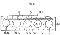
図8は、中間層10の可能な実施形態の概略的な断面図を例示しており、この実施形態は、管状ばね50として実施されている一連の支持要素14を有している。該管状ばね50は、それらが囲むスペース38が中空であるので、上側空気分配手段25として役立つ。それらの上方に配置されているのは加熱素子74であり、これは薄いパッド層で覆われている。その上にあるシート表皮72が同時に表層12を形成する。
FIG. 8 illustrates a schematic cross-sectional view of a possible embodiment of the
図9に略示されたばね50は支持要素14として機能する。このばね50は螺旋状に巻かれている。図10に示された代替例のばね50は、同様に支持要素14を形成する。このばね50は蛇行状に構成されている。
The spring 50 schematically shown in FIG. 9 functions as the
図11と図12は下側空気分配層32の2つの異なる変形例を示している。
11 and 12 show two different variants of the lower
図11は、互いに隣接して平行に担持層52に配置された一連のばね50を例示している。螺旋状のばね50は、担持層52にある支持要素14を形成する。従って、図11は平面的材料から形成される下側空気分配層32の第1変形実施形態を例示している。これにより、代表的には約5mm〜15mmとすることができる比較的に小さい奥行で、空気の案内および分配のための大きな横断面が得られる。この層は、編織担持媒体(担持層52)上に螺旋体を付着することによって得られる螺旋体マットとすることができる。担体はフォームコアまたはシート構造体の方を向くことが有利である。
FIG. 11 illustrates a series of springs 50 disposed on the carrier layer 52 adjacent and parallel to each other . Helical spring 50 forms a supporting
図12は、中間層10の他の可能な実施形態を概略的な斜視図で例示しており、この中間層には、通路状領域84として実施された窪んだ表面領域80が組み入れられている。これらの領域は、隆起した表面領域82によって互いに隔てられている。窪んだ表面領域80の内部にあるばね50がそれぞれ支持要素14として機能する。その結果、単数または複数の通路状溝がフォーム下面に形成され、フォーム下面と平行に延びる。螺旋体は、人がそこに着座するときに通路状溝が崩壊しないように、該通路状溝に支持を提供する。これら通路は、互いに平行に延びていてよく、或いは、送風手段60もしくはファンのある中心から出発して種々のパッド領域へと星形の形状になって外方に延びていてよい。通路の形状は、必要に応じて、選択的に半円形、長方形または台形にすることができる。
FIG. 12 illustrates in a schematic perspective view another possible embodiment of the
乗員に向き合う上側空気分配層25については多数の設計上の選択の余地がある。この層は例えば、編織担持媒体上に螺旋体を付着することによって得られる螺旋構造体マットの形を取ることができる。担体はフォームコアまたはシート構造体の方を向くことができる。 There are many design choices for the upper air distribution layer 25 facing the occupant. This layer can take the form of, for example, a spiral structure mat obtained by depositing a spiral on a textile carrier medium. The carrier can face the foam core or sheet structure.
代案として、層は単数または複数のスペーサー編物層によって形成することもできる。編物は、所要輪郭の通気区画を打ち抜くことによって製造される。上側空気分配層25は選択的に、平面的に成形されるゴム引き布体、剛毛マット、またはその他の空気透過性材料で構成することができる。 As an alternative , the layer can also be formed by one or more spacer knitted layers. The knitted fabric is manufactured by punching out a vent section of the required contour . The upper air distribution layer 25 selectively, it is possible to configure rubberized fabric body to be molded in a planar manner, with bristles mat or other air permeable materials.
他の代替的な構成では、パッドコアは、構造化されたけば立て表面を有することができる。構造化された表面を有する付加的注型発泡部品をフォーム体上に接着しておくこともできる。注型発泡部品は、網状(開放気泡、空気透過性)フォームから製造することができる。構造体はその場合フォームコアの方を向くこともできる。これにより表皮表面で構造体の透通しの減少が達成される。構造体はフォームのエンボス加工または材料除去(フライス加工)によって製造することができる。 In another alternative configuration, Paddokoa may have a structured napping surface. Additional cast foam parts having a structured surface can also be glued onto the foam body. Casting foaming component can be produced reticulated (open cell, air-permeable) from the form. The structure can then face the foam core. This achieves a reduced penetration of the structure on the surface of the skin. Structure can be produced by embossing or material removal form (milling).
図13は、隆起した表面構造54を有する表層12の他の可能な構成例を示している。
FIG. 13 shows another possible configuration example of the
上述したパッドコアを利用したシート接触面の通気はさまざまな仕方で実施することができる。 Aeration of the sheet contact surface using the pad core described above can be performed in various ways.
車両シート20の通気可能な構成例は、図14の略断面図に明らかにされている。車両シートはパッド層22とこの層を少なくとも3つの側面で包む中間層10とを有する。液不透過性層76として構成された基層8は、少なくとも上側空気分配手段25とパッド層22との間に配置されている。その際、車両シートの下方に送風手段60が配置され、これが中間層10内への空気供給をもたらす。送風手段60は、空気を下側空気分配手段32に吹き込むことができ、すると空気は連絡手段35を介して上側空気分配手段25内に移送される。送風手段は、シート構造体またはパッド部品自体に固着しておくことができる。下側通気層はこのため空気流入穴を有する。
An example of a configuration in which the
図15は、車両シートの他の代替実施形態を示しており、該車両シートでは中間層10の短辺面に送風手段60が配置されている。この実施形態において、送風手段60は上側空気分配手段25に通じている。
Figure 15 shows another alternative embodiment of a vehicle seat, in the vehicle seat
図16と図17は、中間層10に送り込まれる空気流の異なる流路を示す。図16は加熱手段なしの車両シートを示すが、図17の図示では平面的加熱素子74が上側空気分配手段25上に配置されている。
16 and 17 show a different channel-air flow is Ru fed into the
図16の実施形態では、下側空気分配手段32が空気流入穴を有しているが、上側空気分配手段25は覆われた空気流出穴を有する。この空気流出穴は、着座乗員が見ることも気付くこともなくシートバックとシートクッションとの間に設けることができ、または該空気流出穴は、シートバックカバーに設けることができ、従って、後部座席乗員に向けておくことができる。シート接触面下の空気流は、暖炉のような方法で空気の加温によって上側空気分配手段もしくは層内に生じる自然対流によって発生する。この加温は乗員の体温がシートパッドに移ることによって起きる。 In the embodiment of FIG. 16, the lower air distribution means 32 has air inflow holes, whereas the upper air distribution means 25 has covered air outflow holes. The air outlet holes may be provided between the seat back and the seat cushion without also notice be seen by the occupant or the air outlet hole, can Rukoto provided in the seat back cover, therefore, the rear Can be pointed at the seat occupant. The air flow under the sheet contact surface is generated by natural convection generated in the upper air distribution means or layers by warming the air in a fireplace- like manner . This warming occurs when the passenger's body temperature is transferred to the seat pad.
図17によれば、上側空気分配層25内での空気の加温は、この上側空気分配層内に設けられる加熱媒体によって行うことができる。空気の加温は、周囲空気との温度差を大きくし、従って対流を強める。それに加えて、暖かい空気は、水分を吸収する高い能力を有する。 According to FIG. 17, heating the air in the upper air distribution layer 25 can be performed by heating medium which is provided in the upper air distribution layer. Warming of air, to increase the temperature difference between the ambient air and thus enhance convection. In addition, warm air has a high ability to absorb moisture .
上側空気分配層25における空気の加温は、選択的にではあるが、車両駐車時の太陽熱の放射によるシート表面の加温によっても生じうる。結果的生じる空気循環は、パッドコア22が過度に加温されるのを防止する。加えて、上側空気分配層25は断熱作用を有している。太陽に照らされたパッドコア22の付加的加温は、熱がフォームおよびシート構造体の熱質量から長時間にわたって身体に熱が供給されるので、走行運転時の乗員にとって熱生理学的に不利に作用するであろう。
The heating of the air in the upper air distribution layer 25 can be caused by the heating of the seat surface by the radiation of solar heat when the vehicle is parked , although it is optional . The resulting air circulation prevents the
図18〜図20は、車両シートに設けられる送風手段60のそれぞれ異なる実施形態を示している。図18は、軸流ファンとして構成された送風手段60を例示しており、この軸流ファンは、中間層10の平面的な広がりに対して垂直に空気を中間層に吹き込む。下側空気分配層32の下面にはスペーサー媒体内への空気入口穴がある。この穴の断面積は軸流ファンの空気出口穴に対応している。螺旋構造体マットにある穴は、表層の切り取りによって結果的に生じる。随意であるが、この表層はファンロータを保護するための枠または格子によって支えられる。
FIGS. 18-20 has each shown different embodiment of the ventilation means 60 provided in a vehicle seat. FIG. 18 illustrates a blowing means 60 configured as an axial fan, and this axial fan blows air into the intermediate layer perpendicular to the planar extent of the
図19は、空気を中間層10の平面的な広がりに沿って該中間層に吹き込むラジアルファンを示している。従って、送風手段60は空気分配層の正面に取り付けられている。アダプタは、ファン出口の横断面形状を空気分配層の平面状入口に適合させている。流体工学上の理由から利用されるのが好ましいラジアルファンは、軸流ファンよりも狭い出口を有し、下から吸込んだ空気を90°転向させて吹き出す。
Figure 19 shows a radial fan blowing on the middle layer along a planar spread between
図20は、中間層10の領域62を図示しており、この領域の一方の末端64に軸流ファンの態様の送風手段60が配置されており、このファンは領域62を通して中間層10の他方の末端66へと空気を移送する。図21は、一方の末端64に送風手段60を有する中間層10の領域62を例示している。他方の末端66は空気を中間層10全体に送る。図20と図21に示す実施形態では、螺旋構造体マットは拡張された連絡通路に通じており、この通路は直径の増大する円形螺旋体によって支えられる。通路末端の流入穴は横断面においてファンの空気出口穴に一致している。通路は、螺旋構造体マットからの延長部、拡張部、および螺旋体の絡み合わせによって選択的に形成しておくこともできる。
FIG. 20 illustrates a
図22は、基層8と、組み入れられた伝導手段42および加熱導体44とを略平面図で例示している。これに加えて、支持要素14が設けられていて、該当加熱導体44を所定位置に保持している。
FIG. 22 illustrates the
図23の略平面図は、基層8に固定された加熱導体44を例示している。加熱導体は基層8上にヘリカル状に布設されている。この実施形態では、互いに平行な若干数もしくは多数の細長い中間スペース88、88’が支持要素14によって形成されている。絶縁された加熱導体44の態様の伝導手段42が中間スペース88、88’内に延設されている。加熱導体44は基層8の一方のスペース88から他方のスペース88’への移行部92に固定されている。図示実施例においてこの固定は付着性材料からなる帯板94によって行われ、これらの帯板はそれぞれ中間スペース88、88’に垂直に配置されている。帯板94を電極として構成しておくことも予定することができる。
Schematic plan view of FIG. 23 illustrates the heating conductor 44 fixed to the
図24は、送風手段60とパッドコア22の周りに配置される中間層10の連絡手段35との間の可能な連絡を例示している。
Figure 24 illustrates a possible contact between the contact means 35 of the
最後に、図25は、パッドコア22の凹部86に挿入することのできる空調装置2を例示している。
Finally, FIG. 25 illustrates the air conditioner 2 that can be inserted into the
図26は特別好ましい実施形態を示している。基層8(或いは表層12)が例示されており、その上に複数の支持要素14が配置されている。本実施形態において、支持要素14は細長い螺旋体の形状を有し、該螺旋体はそれらの長手方向軸線に関して互いにほぼ平行に並置されている。
FIG. 26 shows a particularly preferred embodiment . Group layer 8 (or the surface layer 12) is illustrated, a plurality of
各支持要素14の長手方向軸線に沿って1つの電気導体43が延設されている。この導体43は支持要素14を巻き付けられており、これにより外力の作用から十分に保護されている。電気導体43は加熱ケーブルとすることができる。しかし、ここではフラットケーブル、好ましくは2心ケーブルである。
One
各電気導体43上に少なくとも1つの電気加熱モジュール47が配置されていることが好ましい。各電気導体43上に複数の加熱モジュール47が、好ましくは等間隔で取り付けられているのが有利である。これらは、例えばチタン酸バリウムの半導体セラミックであるPTC素子であることが好ましい。電気導体43の加熱モジュール47は、電気的に互いに並列にボンディング、即ち結合されていることが好ましい。図27は、図26の配置の電気的等価回路図を示す。
Preferably , at least one
複数の電気導体43は、共通の母線45を介して電源に接続されていて、櫛状の導体構造を形成している。母線45は、基層8もしくは表層12の縁のところで電気導体43にほぼ垂直に延びている。
A plurality of
図28は、車両シートに組み付けられた図26の配置を示している。表層12はシート表皮72の下に配置されている。支持要素14は、その中に組み入れられた電気導体43および加熱モジュール47と共に、中間層10内で表層12に沿って延びる。送風手段60は中間層10と流体透過式に連絡されている。
Figure 28 shows the arrangement of Figure 26 attached not assembled to the vehicle seat. The
運転時、加熱モジュール47は抵抗加熱によって暖められる。温度上昇に伴うPTCモジュールの加熱抵抗が特徴的な増加を示す結果として、加熱モジュールの温度制限になるか又は加熱モジュールの熱出力の自己調節になり、従って、この特徴的な増加が加熱モジュールの最終温度を決定する。熱は、主として伝導により、中間層10に閉じ込められた空気を介し、また、乗員96と加熱モジュール47との間にあるシート表皮72に閉じ込められた空気を介して、乗員の身体へと達する。中間層10における空気の層は、対流混合による熱分配に寄与する。送風手段60の付加的な利用により、空気は、中間層10および空気透過性シート表皮72内を移送され、乗員96への対流による熱輸送を生じさせる。この作用は、システム運転についての迅速な認識を高めると同時に、熱分配を改善する。
During operation, the
加熱モジュールの種類、数、密度および寸法の適切な選択に加えて、加熱モジュールの電流レベル、電源投入時間およびPTC効果の調節も熱出力を制御するために利用することができる。 In addition to the proper selection of the type, number, density and dimensions of the heating module, adjustment of the heating module current level , power-on time and PTC effect can also be utilized to control the heat output .
さらに、送風手段60の空気流の調節によって熱出力を制御することが有利である。空気流が増えると、PTCモジュールの対流冷却が高まり、従って、抵抗を低くすることにより、発生される熱出力が増加する。生理学的に有効な熱出力は、特定の空気流量範囲において同様に増加する。 Furthermore, it is advantageous to control the heat output by adjustment of the air flow feed air means 60. As the air flow increases, the convective cooling of the PTC module increases, and thus the generated heat output increases by lowering the resistance. Physiology effective heat output is likewise increased in particular airflow range.
さらに、PTCモジュールの予熱段階後に送風手段の電源投入の時間遅延を予定しておくことができる。これもまた、車両シートヒーターの主観的に知覚される応答特性の向上に寄与することができる。同時に、これは、シート内の初期の冷たい空気を乗員に吹き付けることを回避する。PTCモジュールの大きな投入電流は、車両搭載電気系統が過負荷を受けることのないように、電流制限のために構造ユニット(例えばNTC半導体モジュール)を直列接続することを必要とするかもしれない。 Furthermore, it is possible to schedule a time delay for turning on the air supply means after the preheating stage of the PTC module. This can also contribute to improving the subjectively perceived response characteristics of the vehicle seat heater . At the same time, this avoids blowing the initial cold air in the seat to the occupant. Large making current of the PTC module, car both mounted electrical system so as not to receive the overload, may require to be connected in series structural unit (e.g., NTC semiconductor module) for current limiting.
図28は、中間層10に対する送風手段60の固着の詳細を示している。パッドコア22上には中間層10、表層12およびシート表皮72が配置されている。パッドコア22のほぼ中央に凹部68が設けられており、この凹部は、乗員96から離れた方のパッドコア22の側から中間層10に至るまで、パッドコア22を貫通している。乗員96から離れた方のパッドコア22の側から中間層10に空気を供給するために、凹部68内に送風手段60が配置されている。
Figure 28 shows the details of the fixation of the blowing means 60 to the
送風手段60を中間層10に固着するために固定具97が設けられている。この固定具は、送風手段に設けられる固着手段100と、中間層10に設けられる保持手段98とを有する。
A fixture 97 is provided to fix the blowing means 60 to the
この場合、固着手段100は、送風手段60を中間層に結縛するために、中間層10にある少なくとも1つの支持要素14の数巻きに係合するケーブル結縛具である。この固着方式は、同時に頑丈で、安価であり、機械的荷重に対して十分に可撓性である。しかしケーブル結縛具の代わりに、フックまたはクリップも送風手段60を支持要素14または対応する構造要素に固定するために考えられよう。
In this case, the fixing means 100 is a cable tie that engages several turns of at least one
保持手段98はこの場合、少なくとも1つの支持要素14に固着‐好ましくは溶接‐される短い嵌合管である。この嵌合管は、組立時に送風手段60を案内して所定の位置に入れ、同送風手段をその最終位置に嵌合する。しかし、嵌合管の代わりにフランジまたは類似の機械的装着インタフェースを設けておくこともできる。
The holding means 98 is in this case a short fitting tube which is fixed— preferably welded—to at least one
固定具97は振動減衰器99をも有することが好ましい。この振動減衰器は、上述した実施形態と同様に適当に緩いケーブル結縛具の形を取ることができる。しかし、板または栓の態様のゴム製振動吸収器が利用されることが好ましく、該振動吸収器は好ましくは送風手段60と中間層10との間に配置される。
Fixture 97 preferably has also a dynamic attenuator 99 vibration. This vibration attenuator can take the form of a suitably loose cable tie as in the embodiment described above . However, it is preferable that rubber vibration absorber aspect of the plate or plug is utilized, the vibration absorber is preferably arranged between the blowing means 60 and the
シート表面の除湿は、上側スペーサー媒体内、例えば上側表層12の領域内の水分中間緩衝器によって改善することができる。このような除湿は、シート接触面にたまる水分もしくは水蒸気がパッドによって迅速に吸収され得るので、ひどく汗かきな人が乗車する場合に特に有利に作用することがある。パッドの通気および加熱によって緩衝器は連続的に空にされ除湿される。緩衝器はさまざまな仕方で層中に導入することができる。例えば、螺旋体の空隙および/または螺旋体に囲まれた容積には、水分吸着粒質物、例えば活性炭を充填することができる。螺旋体表面に水分吸着粉末を吹き付けることもできる。粉末の付着は、例えば螺旋体表面上への融解または接着剤被覆の使用によって確実にすることができる。螺旋体マットは水分吸収性の不織布表層を備えることもできる。
Dehumidification of the sheet surface can be improved in the upper spacer medium, for example, by moisture intermediate buffer in the region of the
表皮組立(椅子張り)時およびシート使用時に層の位置ずれを防止するために、空気分配層(中間層10)はパッドコア22としっかり結合されねばならない。この結合は、基本的にさまざまな仕方で実現することができる。例えば、空気分配層は注型発泡プロセスで取り込むことができる(発泡注入)。これにより層の全面的付着が達成される。フィルムまたは密な編織布からなる分離層は、製造プロセス中に液体フォームの浸透を防止し、通路(螺旋体通路)を開口保持する。空気分離層は、選択的に、螺旋体マットの下向き担持層を完全にまたは部分的に補うことができる。
To prevent displacement of the layer at the time of skin assembly (upholstery) and seat use, air distribution layer (intermediate layer 10) must be tightly coupled with
これに対する代案として、空気分配層は、フォームコアの窪みに挿入されるマットの態様で取り込むことができる。窪みはマット外側形状の雌形を形成する。嵌め合い結合によってマットの位置ずれは防止される。 As an alternative to this, air distribution layer can be Komu taken in the manner of a mat which is inserted into the recess of the foam core. The indentation forms a female outer shape of the mat. The mat displacement is prevented by the mating connection.
他の変更態様では、爪、フックまたはベルクロファスナーの態様の取付具がフォームコアに固着されている。これらの取付具は、注型発泡プロセス中にフォームコアに固着されまたは周囲に発泡成形されるのが好ましい。取付具は、空気分配層の微細構造または支持要素に係合する。 In other variations, a fixture in the form of a claw, hook or velcro fastener is secured to the foam core. These fixtures are preferably foamed molded secured to or around the foam core during the casting foaming process. The fixture engages the microstructure or support element of the air distribution layer.
随意であるが、空気分配層は接着結合によってフォームコアに固着することができる。 Optionally, the air distribution layer can be secured to the foam core by adhesive bonding.
最後に、フォーム表面を向く担持層は、スペーサー媒体をこえる形状重複部分を有することができる。編織布層またはフィルム層の重複する縁は接着剤によりフォームコアと結合される。 Finally, the support layer facing the foam surface can have overlapping shapes beyond the spacer medium. Duplicate edges of the textile layer or film layer is combined with the foam core by an adhesive.
シート接触面の領域に快適層を有する注型発泡部品はさまざまな仕方で造形しておくことができる。例えば、加熱媒体はスペーサー媒体と面結合しておくことができる。この複合体は、乗員に向き合う注型フォームコアの上面を覆う。加熱媒体は表面の方を向く外側層を形成する。快適複合体は、製造プロセスの注入発泡成形中に取り込まれるのが好ましく、これにより接着剤のない安定した全面的結合を実現することができる。随意であるが、加熱媒体はスペーサー媒体の一体構成要素とすることもできる。 A cast foam part having a comfort layer in the area of the seat contact surface can be shaped in various ways. For example , the heating medium can be surface bonded to the spacer medium. This complex covers the upper surface of the casting foam core facing the squared members. The heating medium forms an outer layer facing the surface. Comfortable complex can be preferably incorporated into the injection foam molding of the manufacturing process, thereby realizing a stable full binding adhesive-free. Optionally, the heating medium can be an integral component of the spacer medium.
スペーサー媒体についての可能性には、乗員の着座時にパッドに限定的な自由空間が残るように、顕著な圧縮硬さと顕著な回復特性とを有すると共に比較的に軽く曲がる材料がある。それにもかかわらず、乗員の着座快適性が媒体によって損なわれることのないように、媒体は、フォームの各輪郭に比較的容易に適合可能であると共に、著しい広がりなしに圧縮荷重をフォームに伝達可能でなければならない。 The potential for spacer medium, as an occupant limiting free space pad when sitting the left, there is lightly bent material relatively with having a pronounced compression hardness and the remarkable recovery properties. Nevertheless, so as not to seating comfort of the occupant is impaired by the media, the media, as well as a possible relatively easily adapted to each contour of the form, capable of transmitting compressive load to the form without significant broadening It is must in.
例えば、層は、構造化された螺旋体マットの形を取ることもできる。この螺旋体マットは螺旋体(支持要素14)を編織担持媒体(担持層52、図13参照)上に貼り付けることによって得られる。担体はフォームコアまたはシート構造体の方を向くことができる。選択的に、層は、単数または複数のスペーサー編物の層によって形成することもできる。この編物は打抜きによって通気区画の所要の輪郭に製造することができる。 For example, the layer can take the form of a structured spiral mat. This spiral mat is obtained by sticking the spiral body (supporting element 14) onto a woven support medium (supporting layer 52, see FIG. 13). The carrier can face the foam core or sheet structure. Optionally, the layer may be formed by a layer of one or more spacers knitting. This knitted fabric can be manufactured to the required contour of the ventilation section by punching.
これに対する代案として、層は、平面的に成形されたゴム引き布体、剛毛マットまたはその他の空気透過性の材料で構成することができる。 As an alternative to this, the layer may be rubberized fabric body molded in a plan view, consist of bristle mat or other air permeable materials.
パッドコア22は、構造化したけば立て表面を有することができる。随意であるが、構造化した表面を有する追加の注型発泡部品を必要に応じてフォーム体に接着しておくこともできる。注型発泡部品は、特に、網状(開放気泡、空気透過性)フォームから製造することができる。この構造体は、必要に応じてフォームコアの方を向くことができる。これにより表皮表面での構造体の透き通しの減少が達成される。構造化は、フォームのエンボス加工または材料除去(例えばフライス加工)によってもたらすことができる。
The
平面的加熱媒体は、貼合せプロセスにおいて接着層によってスペーサー媒体と接合することができる。加熱により活性化される又は過熱蒸気で活性化される接着不織布が使用されるのが好ましい。平面的加熱媒体は、平面状の担体に布設または接着される加熱導体で構成することができる。これはまた、縫製/編製プロセスにおいて編織担体に付着される平行な炭素繊維の網状組織で形成することもできる。加熱媒体は、随意であるが、担体フィルム上の金属被覆から構成しておくこともできる。最後に、加熱媒体の代替変形例は伝導性プラスチック層を含むことができる。このプラスチックは、温度の増加に伴って比導電率が低下することを特徴としている(PTC)。加熱電流は、パッド表面に垂直な2つの電極層の間に流れる。従って、熱出力は、熱の除去の関数として地域的に異なることがある。 Planar pressurized heating medium can be joined to the spacer medium by an adhesive layer in lamination process. Adhesive nonwovens that are activated by heating or activated by superheated steam are preferably used . Planar heating medium may be composed of a heating conductor which is laid or glued to a planar carrier. It can also be formed of a network of parallel carbon fibers that are attached to the woven carrier in a sewing / knitting process. Heating medium is a optionally may be so constituted of a metal coating on the carrier film. Finally, alternative variations of the heating medium can include a conductive plastic layer. This plastic has a specific conductivity with increasing temperature is characterized by decreased (PTC). A heating current flows between two electrode layers perpendicular to the pad surface . Thus, the heat output can vary locally as a function of heat removal .
ホースは、転向点における接着点によって担体に固定することができ、または担体の張り出した縁にある接着ストリップ上に保持することができる。 The hose can be secured to the carrier by an adhesive point at the turning point, or can be held on an adhesive strip at the overhanging edge of the carrier .
他の代替変形例は、熱可塑性プラスチックの螺旋体の熱可塑性表面を加熱によって融解することを可能としている。加熱は、例えば、照射、熱風、または導体自体の加熱によって行うことができる。これにより、導体が螺旋体に接触する箇所に接着点が形成され、これらの接着点は熱可塑性プラスチックの硬化後に機械的結合をもたらす。 Another alternative modification, it is made possible to melt the thermoplastic surface of the spiral of thermoplastics by heating. The heating can be performed, for example , by irradiation, hot air, or heating of the conductor itself. This creates bond points where the conductor contacts the helix, which provides a mechanical bond after the thermoplastic is cured.
また、加熱導体の各々は、摩耗保護材として役立つ絶縁ジャケットを有することができる。 Each of the heating conductors can also have an insulating jacket that serves as a wear protection.
フォームに対するスペーサー媒体の結合は、以下の如くに実施することができる。空気分配層は、注型発泡プロセス中に混入(発泡注入)することができる。これにより層の全面的付着が達成される。フィルムまたは密な編織布からなる空気分離層は、製造プロセス中の液体フォームの浸透を防止すると共に、通路(螺旋体通路)を開口保持する。空気分離層は螺旋体マットの上向き担持層を完全にまたは部分的に補うことができる。空気分離層の張り出し端部は、スペーサー媒体の側縁を同様に保護する。この張り出し端部は、スペーサー媒体の周りに巻き付けられてその上面に固定することができる。 The binding of the spacer medium to the foam can be carried out as follows. The air distribution layer can be incorporated (foam injection) during the casting foaming process. This achieves full adhesion of the layer. Air separation layer consisting of a film or dense textile serves to prevent the penetration of liquid foam during the manufacturing process, opening holds a passage (spiral path). The air separation layer can fully or partially supplement the upwardly carrying layer of the spiral mat. The overhanging end of the air separation layer similarly protects the side edges of the spacer medium. This overhang end can be wrapped around the spacer medium and secured to its upper surface.
充填された中間スペースを有する構造化された螺旋体マットについての可能な実施形態を以下に詳しく説明する(図11と図12も参照)。シート接触面の領域に快適層を有する注型発泡部品は、以下の如くに構成しておくことができる。快適層は、構造化された螺旋体マットからなる。該螺旋体マットは、螺旋体を編織担持媒体に貼り付けることによって得られる。担体はフォームコア22またはシート構造体の方を向くことができる。担体への螺旋体の貼り付けは、熱可塑性材料の帯材の融解により行うことができる。
Possible embodiments for structured spiral mats with filled intermediate spaces are described in detail below (see also FIGS. 11 and 12). Note foaming component having a comfort layer in a region of the sheet contact surface, may have been constructed as follows. Comfort layer is made of a structured helix mat. The spiral mat is obtained by pasting the helix to knitting or weaving bearing media. The carrier can face the
構造化された螺旋体マット自体は、軽く曲がると共に、高い圧縮硬さと大きな回復特性とを有するスペーサー媒体であるので、乗員の着座時に限定的な自由空間が維持される。それにもかかわらず、媒体は、フォーム内の各輪郭に容易に適合可能であると共に、広がることなく圧縮荷重をフォームに伝えることができる。その結果、媒体がパッドの着座快適性を損なうことはない。 Structured helix mat itself, together with bend lightly, because a spacer medium having a high compression hardness and large recovery properties, limiting the free space is maintained at the passenger seating. Nevertheless, the medium can be conveyed easily with adaptable to each contour in the form, the compressive load without spreading to form. As a result, the medium does not impair the seating comfort of the pad .
螺旋体マットにある自由空間には、快適性を強化する材料を充填することができる。これらの自由空間は、随意であるが、導体を引き回すために、また、センサおよび/またはアクチュエータを収容するために利用することもできる。未充填のスペーサー材料のパッド特性は十分に維持されねばならず、それが利用可能な容積の一部のみが充填される理由である。この充填物は、例えば玉、フロックまたは顆粒で構成することができる。例えば断熱性スチロフォームもしくはポリスチレンからなる小玉が充填材料として考慮の対象となる。この充填材料は、車両駐車時の日射によるフォームコアの加温が僅かとなる。パッドコアに蓄えられた熱は、走行運転時に乗員にとって熱生理的に不利に作用する。上側層は冬季条件のときにも断熱作用を有するので、冷たい車両シートのフォームコアに伝達される体熱が少なくなる。 The free space in the spiral mat can be filled with a material that enhances comfort. These free space, but is optional, for routing the conductors, can also be utilized to accommodate the sensor and / or actuator. The pad properties of the unfilled spacer material must be maintained well, which is why only a portion of the available volume is filled. The filling can be composed of balls, flocks or granules , for example. For example Kodama consisting heat insulation Suchiro foam or polystyrene is subject to consideration as a filling material. This filling material slightly heats the foam core due to solar radiation when the vehicle is parked . Heat stored in the Paddokoa is thermally physiologically adversely acting to occupant during a driving operation. Since the upper layer has a heat insulating effect even when winter conditions, body heat is less transmitted to the foam core of the cold vehicle seat.
充填物は、例えば、シート環境の快適性を向上させる効果を有することのできる例えば活性炭のような、水分吸着性粒質物で構成することもできる。 The filling can also be composed of a moisture-adsorbing granulate , such as activated carbon, which can have the effect of improving the comfort of the seat environment , for example.
良好なパッド快適性と十分な回復特性とをもたらすことのできる再生発泡フロックも充填物として適している。 Recycled foam flocks that can provide good pad comfort and sufficient recovery properties are also suitable as fillers.
充填物としての粒質物/発泡フロック混合物は、良好なパッド快適性、十分な回復特性および改良されたシート空調快適性をもたらす。 Granulate / foam floc mixture as fillers leads to good pad comfort, adequate recovery properties and improved seat air conditioning comfort.
最後に、充填物は、シート空調快適性および熱的快適性の向上をやはりもたらすことのできる動物性および/または植物性天然繊維で構成することもできる。 Finally, the filling can also be composed of animal and / or vegetable natural fibers that can also provide improved seat air conditioning comfort and thermal comfort.
螺旋体マット内の自由空間はセンサを収容するのに利用することができる。これに適しているのは、例えば、いわゆるシート占有検知用の圧力センサである。これらセンサがフィルム状に構成されている場合、該センサは螺旋体マットの下に配置されることが好ましい。螺旋体マットは、圧力情報を下向きにさらに伝える性質を有する。これにより、センサが表皮近傍もしくは表面近傍に組み付けられると仮定したらシート利用によって発生し得る破損からシートが保護される。 Free space in the spiral mat can be used to accommodate the sensor. Suitable for this is , for example, a so-called sheet occupancy detection pressure sensor. If these sensors are configured in the form of a film, the sensor is Rukoto disposed below the screw旋体mat is preferred. The spiral mat has a property of further transmitting pressure information downward. Thus, the sensor sheet is Ru are protected against damage that obtained caused by the seat utilizing Once assembled saw lighted Ru and assumed near the skin near or surface.
考えられるその他のセンサには、シート暖房および/または空調制御のための温度センサ、シート空調手段を制御するための水分センサ、シートヒーターのためのサーモスタット、および/またはシート調整部およびその他の電気機械的快適性要素を操作するための操作スイッチまたは圧力センサがある。螺旋体マット内の自由空間は、随意であるが、のためのアクチュエータを収容するのに利用することができる。 Other possible sensors include temperature sensors for seat heating and / or air conditioning control, moisture sensors for controlling seat air conditioning means , thermostats for seat heaters , and / or seat adjusters and other electrical machines There are operating switches or pressure sensors for operating the physical comfort element. Free space in the spiral mat is optional, but can be utilized to accommodate an actuator for.
もちろん、螺旋体マット内の自由空間は、導体(伝導手段42、加熱導体44)を収容するのにも利用することができる。このような方法で、導体は、組立時およびシート使用時に破損から保護される。さらに、ラインもしくは導体は、利用者により気付かれることがなく、また、使用中に内張り面に跡をつけることもない。考えられるこのような導体には、特に、加熱導体、シートヒーターおよび/またはシート調整部に給電するための丸形ケーブル、シートヒーターおよび/またはシート調整部に給電するためのリボンケーブル、空圧式シート調整部用の供給ホース、および/またはシートヒーターおよび/またはシート冷却手段用の送液ホースがある。 Of course, the free space in the spiral mat can also be used to accommodate the conductors (conducting means 42, heating conductor 44). In this way, the conductors are protected from damage during assembly and during sheet used. Further, the line or conductor, without withering care-by the user, also, nor put a trace lining surface during use. This is considered such conductors, in particular, the heating conductor, seat heater and / or the seat adjuster round cables for supplying power to, seat heater and / or ribbon cables for supplying power to the seat adjuster, pneumatic seat supply hose for adjusting unit, and / or there is a seat heater and / or liquid feed hose sheet cooling means.
快適層と称される、フォームコア全体にわたり連続的に広がる層は、パッド上面とパッド下面との間の結合を行っている。これは、パッドコア22の前面または後方側面を包むマット状構造の部材(中間層10)によって達成することができる。パッドコア22は、乗員がそこに座っても、この層に引き回された導体を損傷させうる層の折れ曲がりができないような方法で、丸められている。さらに、こうして導体の引き回しが隠されるので、その後、利用者は見ることも気付くこともできない(例えば図4も参照)。
Called comfort layer, a layer that extends continuously over the entire foam core is to bond between the pad top surface and the pad bottom surface. This can be achieved by a mat-like structure member (intermediate layer 10) that wraps around the front or rear side surface of the
螺旋媒体用の担持層は以下の性質を有することができる。表層は、編織媒体またはフォームによって形成することができるので、充填粒質物、導体、センサまたは螺旋体自体のパッド表面上の透き通しを防止することができる。この表層は広メッシュまたは開放気泡とすることができる。しかしながら、粒質物は、シートの使用中であっても、表層を貫通することがあってはならない。 The support layer for the spiral medium can have the following properties. Surface layer, can be formed by knitted woven medium or foam, it is possible to prevent filling granulate, conductor, the show-through on the pad surface of the sensor or helix itself. This surface layer can be a wide mesh or open cells. However, granulates, even during use of the sheet, it shall not be possible to penetrate the surface.
さらに、表層は、この層の下にある媒体および部材を液体の浸入から保護しかつ同時にシート環境の快適性を保つために、蒸気透過性、撥水性とすることができる。 Further, the surface layer, the medium and the member under this layer in order to maintain the comfort suitability of protected and simultaneously seat environment from penetration of the liquid, can be vapor-permeable, water-repellent to.
表層については、シートのパッド特性とパッド表面の触覚性とを付加的に向上させる多種の材料が考えられる。かかる材料は、不織布、編織布、フォームまたはフィルムとすることができる。螺旋体媒体への接着剤結合の実施は選択を制限する効果をもつことができる。 For the surface layer, various materials makes additionally improve the tactile pad characteristics and the pad surface of the sheet is considered. Such a material can be a nonwoven fabric, a knitted fabric, a foam or a film. Implementation of adhesive bonding to the helical media can have the effect of limiting the choice .
また、表層は、パッド表面の照明が可能であるように、穿孔された表皮面に関連する光透過性フィルムとシート内の発光媒体とを有することができる。この照明は、操作要素の位置、センサ位置および/または快適性要素の機能状態を視覚化するのに利用することができる。 Further, the surface layer, as is possible illumination of the pad surface may have a light emitting medium of the light transmissive film and the sheet associated with the perforated skin surface. This illumination can be used to visualize the position of the operating element, the sensor position and / or the functional state of the comfort element.
それに加えて、このような照明によってシートデザインの視覚的価値上昇を達成することができる。 In addition, such lighting can achieve an increased visual value of the sheet design.
螺旋構造体の幾何学的および設計上の自由度は、フォームコア全体の選択的な代用を可能とする。複数の螺旋体層、大きな螺旋体横断面積および/または互いに絡み合った螺旋体の使用により、容積の大きい成形体の構成が達成される。表面プロフィルの加工は、熱塑性の変形性のため最終製造ステップとして行うことができる。 Geometric and design freedom of the helical structure, and possible selective substitution of the entire foam core. Through the use of multiple spiral layers, large spiral cross-sectional areas and / or intertwined spirals, a high volume compact configuration is achieved. The processing of the surface profile can be performed as a final manufacturing step due to thermoplastic deformability .
表皮材と裏当てとの複合体自体は螺旋媒体の担持層として使用することができる。その結果、パッドコアと表皮と懸架ばねとからなるシートパッド全体は、単一の構造ユニットと取り替えられる。 The composite of the skin material and the backing itself can be used as a support layer for the spiral medium . As a result , the entire seat pad consisting of the pad core, the skin and the suspension spring is replaced with a single structural unit.
車両の車室用空調装置は、基層8と、この基層8に少なくとも部分的に覆い合わせて配置されると共に乗員96に向き合う表層12と、基層8および表層12の間に配置される中間層10とを有し、この中間層がうず巻きばねの態様の少なくとも1つの支持要素14を有し、この支持要素が基層8と表層12とを離間保持して両者間に中空スペース37を空けておき、この中空スペース37内に配置される少なくとも1つの電気導体43を有する。
Cabin air-conditioning system of a vehicle, a
空調装置が少なくとも1つの電気加熱素子49を有すると共に、電気導体43および/または電気加熱素子49が加熱導体44から構成されるようにすることができる。
With air conditioning system having at least one electrical heating element 49,
電気導体43が、少なくとも部分的に支持要素14に沿って、好ましくは支持要素14の螺旋体に囲まれたスペース3の内側および/または外側に延びる、ように設備することができる。
複数の電気導体38または導体区域41、41’を設け、これらを、電気的に互いに並列に接続しおよび/または互いにほぼ平行に引き回すと共に、少なくとも1つの共通する母線45を介して、および/または一方の導体区域41の末端を隣接する導体区域41’の各一方の末端と交互に結合することによって、互いに結合する、ように設備することができる。
A plurality of
少なくとも1つの導体43が、好ましくはPTC特性の加熱抵抗を有する少なくとも1つの加熱モジュール47、好ましくはチタン酸バリウムを有する半導体セラミックを備える、ように設備することができる。
At least one
少なくとも1つの導体43が、好ましくは電気的に互いに並列に接続される複数の加熱モジュール47を備える、ように設備することができる。
At least one
電気導体43がフラットケーブルおよび/またはフラット導体によって形成される、ように設備することができる。
装置が、間接的または直接的な固定具97を介して支持要素14に固着される送風手段60を有する、ように設備することができる。
Device has a blowing means 60 which is fixed indirectly or supporting
固定具が少なくとも1つの支持要素14に保持手段98‐特に溶接された保持板または案内嵌め管‐を有し、この案内嵌め管に送風手段60を組み立てることができ、送風手段60が固着手段100‐特にフック、クリップまたはケーブル結縛具‐を有し、この固着手段によって送風手段60が少なくとも1つの支持要素14に固着可能であり、および/または固定具97が少なくとも1つの振動減衰器99’を有し、主にゴム栓の態様のこの振動減衰器が送風手段60から支持要素14への振動伝達を減衰する、ように設備することができる。
The fixture has holding means 98 on the at least one
加熱素子49の熱出力の調節は加熱素子49のPTC特性および/または送風手段60の体積流量により行う、ように設備することができる。 Regulation of the heat output of the heating element 49 is performed by the volumetric flow rate of the PTC characteristics and / or blowing means 60 of the heating element 49, it can be accommodated as.
2 受容装置
3 装置
8 基層
10 中間層
12 表層
14 支持要素
18 機能要素
20 車両シート
22 パッドコア
25 上側空気分配手段
27 パッドコアの前側
30 パッドコアの裏側
32 下側空気分配手段
35 連絡手段
37 スペース
38 スペース
40 センサ
41、41’ 線路区域
42 伝導手段
43 電気導体
44 加熱導体
45 母線
46 アクチュエータ
47 加熱モジュール
48 充填体
49 電気加熱素子
50 ばね
52 担持層
54 表面構造体
60 送風手段、‐ユニット
62 中間層の領域
64 領域の一方の末端
66 領域の他方の末端
68 パッドコアの凹部
70 中間層の個別区域
72 シート表皮
74 加熱素子
76 液不透過性層
80 窪んだ表面領域
82 隆起した表面領域
84 通路状領域
86 パッドコアの凹部
88 支持要素の間のスペース
90 中間層内のスペース
92 移行部
94 帯板
96 乗員
97 固定具
98 保持手段
99 振動減衰器
100 固着手段
2 receiving device 3
18
Claims (14)
Applications Claiming Priority (3)
| Application Number | Priority Date | Filing Date | Title |
|---|---|---|---|
| DE10311861 | 2003-03-17 | ||
| DE20320371U DE20320371U1 (en) | 2003-03-17 | 2003-06-10 | Arrangement for accommodating functional elements in parts of a vehicle interior, comprises an intermediate layer with at least one support element for load transfer between base and cover layers |
| PCT/DE2004/000540 WO2004082989A2 (en) | 2003-03-17 | 2004-03-17 | Device for receiving functional elements |
Publications (2)
| Publication Number | Publication Date |
|---|---|
| JP2006514571A JP2006514571A (en) | 2006-05-11 |
| JP4018717B2 true JP4018717B2 (en) | 2007-12-05 |
Family
ID=33030899
Family Applications (1)
| Application Number | Title | Priority Date | Filing Date |
|---|---|---|---|
| JP2005501725A Expired - Fee Related JP4018717B2 (en) | 2003-03-17 | 2004-03-17 | Receiving device for receiving functional elements |
Country Status (4)
| Country | Link |
|---|---|
| US (1) | US7695062B2 (en) |
| JP (1) | JP4018717B2 (en) |
| DE (1) | DE112004000883D2 (en) |
| WO (1) | WO2004082989A2 (en) |
Families Citing this family (34)
| Publication number | Priority date | Publication date | Assignee | Title |
|---|---|---|---|---|
| US6893086B2 (en) | 2002-07-03 | 2005-05-17 | W.E.T. Automotive Systems Ltd. | Automotive vehicle seat insert |
| US6857697B2 (en) | 2002-08-29 | 2005-02-22 | W.E.T. Automotive Systems Ag | Automotive vehicle seating comfort system |
| DE10259621B4 (en) | 2002-12-18 | 2005-12-01 | W.E.T. Automotive Systems Ag | Vehicle seat and associated air conditioning device |
| DE10259648B4 (en) | 2002-12-18 | 2006-01-26 | W.E.T. Automotive Systems Ag | Air-conditioned seat and air conditioning device for a ventilated seat |
| US7356912B2 (en) | 2003-09-25 | 2008-04-15 | W.E.T. Automotive Systems, Ltd. | Method for ventilating a seat |
| US7274007B2 (en) | 2003-09-25 | 2007-09-25 | W.E.T. Automotive Systems Ltd. | Control system for operating automotive vehicle components |
| US7425034B2 (en) | 2003-10-17 | 2008-09-16 | W.E.T. Automotive Systems Ag | Automotive vehicle seat having a comfort system |
| US7370911B2 (en) | 2003-10-17 | 2008-05-13 | W.E.T. Automotive Systems, Ag | Automotive vehicle seat insert |
| US7461892B2 (en) | 2003-12-01 | 2008-12-09 | W.E.T. Automotive Systems, A.C. | Valve layer for a seat |
| US8288693B2 (en) | 2004-03-08 | 2012-10-16 | W.E.T. Automotive Systems Ag | Flat heating element |
| DE102005018445B3 (en) | 2005-04-20 | 2006-06-29 | W.E.T. Automotive Systems Ag | Air conditioning device for e.g. vehicle seat has air-conditioning zones, which are connected to recess by connecting device whereby recess allows the air to pass through it partially in transverse direction inspite of cover |
| US7478869B2 (en) | 2005-08-19 | 2009-01-20 | W.E.T. Automotive Systems, Ag | Automotive vehicle seat insert |
| US9241373B2 (en) | 2007-10-18 | 2016-01-19 | Gentherm Gmbh | Air conditioning device for seats |
| DE102007056465B4 (en) * | 2007-11-22 | 2010-06-02 | I.G. Bauerhin Gmbh | Motor vehicle seat with seat heating |
| KR101169257B1 (en) | 2007-12-10 | 2012-08-02 | 베.에.테. 오토모티브 시스템스 아게 | Improved seat conditioning module and method |
| DE102008017965B4 (en) * | 2008-04-08 | 2011-06-01 | W.E.T. Automotive Systems Ag | aerator |
| DE202009017046U1 (en) | 2008-12-21 | 2010-05-12 | W.E.T. Automotive Systems Ag | aerator |
| US8864238B2 (en) * | 2009-03-02 | 2014-10-21 | Bridgestone Corporation | Seat pad |
| US8220869B2 (en) * | 2009-10-30 | 2012-07-17 | Ford Global Technologies, Llc | Temperature-and-humidity-controlled head restraint |
| DE102010005994B4 (en) | 2010-01-27 | 2022-07-28 | Tianjin Shenglong Fibre Co., Ltd. | Method for producing a hybrid upholstery element, in particular a seat and backrest upholstery element for use in a motor vehicle, an upholstery element and a vehicle seat with an upholstery element. |
| DE202011102425U1 (en) | 2010-07-15 | 2011-11-08 | W.E.T. Automotive Systems Ag | Electrical line |
| WO2013068578A1 (en) * | 2011-11-11 | 2013-05-16 | Sympatex Technologies Gmbh | Seat and use thereof |
| CN103832302B (en) * | 2012-11-22 | 2016-06-08 | 清华大学 | Automotive seat |
| US9168852B2 (en) | 2012-12-03 | 2015-10-27 | Ford Global Technologies, Llc | Climate comfort seat assembly |
| FR3024683B1 (en) * | 2014-08-08 | 2018-02-23 | Faurecia Sieges D'automobile | THERMAL DEVICE FOR SEAT OF MOTOR VEHICLE |
| EP3135532B1 (en) * | 2014-10-07 | 2017-09-20 | C.R.F. Società Consortile per Azioni | Motor vehicle having a seat provided with a system for supplying conditioned air |
| US11167673B2 (en) | 2017-07-25 | 2021-11-09 | Faurecia Automotive Seating, Llc | Vehicle seat |
| US10674830B1 (en) * | 2017-09-22 | 2020-06-09 | Tramec Termico Technologies, L.L.C. | Self-regulating heated seat cushion |
| US10479243B2 (en) | 2017-12-05 | 2019-11-19 | Ford Global Technologies, Llc | Air channel thermocomfort foam pad |
| CN110997403A (en) * | 2018-01-22 | 2020-04-10 | 帕德米尼维纳电子机械公司 | Flexible heat exchanger for thermal control of seat surfaces |
| US10464454B1 (en) * | 2018-07-24 | 2019-11-05 | Ford Global Technologies, Llc | Vehicle seat having moisture sensing |
| WO2020030725A1 (en) * | 2018-08-08 | 2020-02-13 | Adient Engineering and IP GmbH | Foam part, in particular for a vehicle seat, and method for producing a foam part |
| US11832728B2 (en) * | 2021-08-24 | 2023-12-05 | Sleep Number Corporation | Controlling vibration transmission within inflation assemblies |
| DE102021127989B4 (en) * | 2021-10-27 | 2024-04-04 | Faurecia Autositze Gmbh | Seat element, in particular the headrest of a vehicle seat |
Family Cites Families (22)
| Publication number | Priority date | Publication date | Assignee | Title |
|---|---|---|---|---|
| US1541213A (en) | 1922-12-11 | 1925-06-09 | Erskine P Harley | Seat cushion |
| US2922466A (en) | 1958-06-02 | 1960-01-26 | Oliver F Marston | Seat cushion |
| US2992604A (en) | 1958-06-09 | 1961-07-18 | Trotman | Forced air under body ventilating device |
| US3576040A (en) * | 1968-10-21 | 1971-04-27 | Conwed Corp | Spring cushion structures |
| SE463090B (en) * | 1986-09-17 | 1990-10-08 | Scandmec Mecania Ab | Procedure for producing a heated cushion having one or more resilient layers provided with heating cable |
| DE3820095A1 (en) * | 1988-06-13 | 1989-12-21 | Gore W L & Ass Gmbh | COVER MATERIAL FOR UPHOLSTERED BEDS AND SEATS |
| DE4014550A1 (en) * | 1989-05-16 | 1990-11-22 | Volkswagen Ag | Upholstered car seat with air induction fan for perspiration removal - uses internal negative pressure source and simple seat modification for searching aeration of porous upholstery |
| US5002336A (en) * | 1989-10-18 | 1991-03-26 | Steve Feher | Selectively cooled or heated seat and backrest construction |
| US4997230A (en) * | 1990-01-30 | 1991-03-05 | Samuel Spitalnick | Air conditioned cushion covers |
| DE19703516C1 (en) * | 1997-01-31 | 1998-05-07 | Daimler Benz Ag | Vehicle seat with upholstery heating and cooling |
| US6229123B1 (en) * | 1998-09-25 | 2001-05-08 | Thermosoft International Corporation | Soft electrical textile heater and method of assembly |
| DE19805174C1 (en) * | 1998-02-10 | 1999-06-02 | Daimler Chrysler Ag | Motor vehicle heated seat with seat and backrest cushions containing air passages and electric fans |
| DE19847384C1 (en) * | 1998-10-14 | 2000-06-21 | Daimler Chrysler Ag | Upholstery for seat part and / or backrest of a vehicle seat |
| FR2790430B1 (en) * | 1999-03-01 | 2001-05-18 | Faure Bertrand Equipements Sa | VEHICLE SEAT THERMAL REGULATION METHOD AND SYSTEM |
| SE514578C2 (en) * | 2000-03-02 | 2001-03-12 | Lear Corp | Vehicle seat and procedure for its comfort ventilation |
| DE10195699D2 (en) * | 2000-12-23 | 2003-12-04 | Lindner Manfred K | Surface heating and process for its manufacture, and heatable object |
| US6489595B1 (en) * | 2001-03-12 | 2002-12-03 | Check Corporation | Electric heater for a seat assembly |
| US6505886B2 (en) * | 2001-04-04 | 2003-01-14 | Visteon Global Technologies, Inc. | Climatized seat with vortex tube |
| DE10228406B4 (en) | 2001-06-25 | 2016-09-15 | Bernhard Scheuring | Use of a composite component and method for producing the composite component used |
| JP2004073429A (en) * | 2002-08-15 | 2004-03-11 | Nhk Spring Co Ltd | Breathable sheet |
| AU2003290662A1 (en) * | 2002-11-05 | 2004-06-07 | Witchie, Ronald, G. | An arrangement and method for providing an air flow within an upholstered seat |
| DE102006052935A1 (en) * | 2005-11-10 | 2007-06-14 | W.E.T. Automotive Systems Ag | Temperature-conditioned motor vehicle seat, has insert comprising cushioning layer that is arranged between cushion and outer fabric surface, and airflow arrangement provided for heating, cooling and air-conditioning function |
-
2004
- 2004-03-17 JP JP2005501725A patent/JP4018717B2/en not_active Expired - Fee Related
- 2004-03-17 US US10/549,517 patent/US7695062B2/en not_active Expired - Fee Related
- 2004-03-17 DE DE112004000883T patent/DE112004000883D2/en not_active Expired - Fee Related
- 2004-03-17 WO PCT/DE2004/000540 patent/WO2004082989A2/en active Application Filing
Also Published As
| Publication number | Publication date |
|---|---|
| US20060267260A1 (en) | 2006-11-30 |
| WO2004082989A3 (en) | 2004-12-23 |
| JP2006514571A (en) | 2006-05-11 |
| US7695062B2 (en) | 2010-04-13 |
| DE112004000883D2 (en) | 2006-02-02 |
| WO2004082989A2 (en) | 2004-09-30 |
Similar Documents
| Publication | Publication Date | Title |
|---|---|---|
| JP4018717B2 (en) | Receiving device for receiving functional elements | |
| JP4053569B2 (en) | Device for air conditioning a vehicle seat | |
| US11240882B2 (en) | Conductive convective climate controlled seat | |
| JP4926078B2 (en) | Automotive ventilation, temperature control and ergonomic comfort system | |
| US6629725B1 (en) | Seat part for a vehicle seat | |
| KR100554640B1 (en) | Automotive vehicle seat and blower module for such an automotive vehicle seat | |
| US8066324B2 (en) | Reduced power heat mat | |
| KR101054489B1 (en) | Ventilated seat with front breathable material | |
| JP2006516102A (en) | Air conditioner for vehicle compartment | |
| US20080111403A1 (en) | Module for a cushion | |
| EP3359418B1 (en) | Thermally conductive padding | |
| EP2156705A1 (en) | Heating pad for use with animals | |
| KR20160090876A (en) | Ventilation system | |
| US20110221242A1 (en) | Air conditioning device for seats | |
| CA2293340A1 (en) | Supporting part for a seat | |
| JP2005170369A (en) | Air distributor | |
| US20070245760A1 (en) | Devices for air conditioning, detecting, and seating | |
| CN1902066B (en) | Air-conditioning device for the passenger area of a vehicle | |
| DE10326445B4 (en) | Device for air conditioning a vehicle seat | |
| CN100467306C (en) | Device for receiving functional elements | |
| KR101948562B1 (en) | Multi-layer heating wire mat | |
| CN214381453U (en) | Carbon fiber heating cushion for automobile | |
| KR20200000191U (en) | Heating mat for four season with ventilating function | |
| KR200278864Y1 (en) | Electric mattress for a bed | |
| KR20230007834A (en) | the bedding in which the carbon fiber layer gets ready |
Legal Events
| Date | Code | Title | Description |
|---|---|---|---|
| RD04 | Notification of resignation of power of attorney |
Free format text: JAPANESE INTERMEDIATE CODE: A7424 Effective date: 20060327 |
|
| A977 | Report on retrieval |
Free format text: JAPANESE INTERMEDIATE CODE: A971007 Effective date: 20070205 |
|
| A131 | Notification of reasons for refusal |
Free format text: JAPANESE INTERMEDIATE CODE: A131 Effective date: 20070221 |
|
| A601 | Written request for extension of time |
Free format text: JAPANESE INTERMEDIATE CODE: A601 Effective date: 20070518 |
|
| A602 | Written permission of extension of time |
Free format text: JAPANESE INTERMEDIATE CODE: A602 Effective date: 20070525 |
|
| A601 | Written request for extension of time |
Free format text: JAPANESE INTERMEDIATE CODE: A601 Effective date: 20070619 |
|
| A602 | Written permission of extension of time |
Free format text: JAPANESE INTERMEDIATE CODE: A602 Effective date: 20070626 |
|
| A521 | Request for written amendment filed |
Free format text: JAPANESE INTERMEDIATE CODE: A523 Effective date: 20070717 |
|
| TRDD | Decision of grant or rejection written | ||
| A01 | Written decision to grant a patent or to grant a registration (utility model) |
Free format text: JAPANESE INTERMEDIATE CODE: A01 Effective date: 20070822 |
|
| A61 | First payment of annual fees (during grant procedure) |
Free format text: JAPANESE INTERMEDIATE CODE: A61 Effective date: 20070920 |
|
| R150 | Certificate of patent or registration of utility model |
Ref document number: 4018717 Country of ref document: JP Free format text: JAPANESE INTERMEDIATE CODE: R150 Free format text: JAPANESE INTERMEDIATE CODE: R150 |
|
| FPAY | Renewal fee payment (event date is renewal date of database) |
Free format text: PAYMENT UNTIL: 20100928 Year of fee payment: 3 |
|
| FPAY | Renewal fee payment (event date is renewal date of database) |
Free format text: PAYMENT UNTIL: 20100928 Year of fee payment: 3 |
|
| FPAY | Renewal fee payment (event date is renewal date of database) |
Free format text: PAYMENT UNTIL: 20110928 Year of fee payment: 4 |
|
| R250 | Receipt of annual fees |
Free format text: JAPANESE INTERMEDIATE CODE: R250 |
|
| FPAY | Renewal fee payment (event date is renewal date of database) |
Free format text: PAYMENT UNTIL: 20110928 Year of fee payment: 4 |
|
| FPAY | Renewal fee payment (event date is renewal date of database) |
Free format text: PAYMENT UNTIL: 20120928 Year of fee payment: 5 |
|
| R250 | Receipt of annual fees |
Free format text: JAPANESE INTERMEDIATE CODE: R250 |
|
| FPAY | Renewal fee payment (event date is renewal date of database) |
Free format text: PAYMENT UNTIL: 20130928 Year of fee payment: 6 |
|
| R250 | Receipt of annual fees |
Free format text: JAPANESE INTERMEDIATE CODE: R250 |
|
| R250 | Receipt of annual fees |
Free format text: JAPANESE INTERMEDIATE CODE: R250 |
|
| R250 | Receipt of annual fees |
Free format text: JAPANESE INTERMEDIATE CODE: R250 |
|
| S111 | Request for change of ownership or part of ownership |
Free format text: JAPANESE INTERMEDIATE CODE: R313111 |
|
| R350 | Written notification of registration of transfer |
Free format text: JAPANESE INTERMEDIATE CODE: R350 |
|
| R250 | Receipt of annual fees |
Free format text: JAPANESE INTERMEDIATE CODE: R250 |
|
| R250 | Receipt of annual fees |
Free format text: JAPANESE INTERMEDIATE CODE: R250 |
|
| R250 | Receipt of annual fees |
Free format text: JAPANESE INTERMEDIATE CODE: R250 |
|
| R250 | Receipt of annual fees |
Free format text: JAPANESE INTERMEDIATE CODE: R250 |
|
| R250 | Receipt of annual fees |
Free format text: JAPANESE INTERMEDIATE CODE: R250 |
|
| LAPS | Cancellation because of no payment of annual fees |