JP4018513B2 - Liquid storage device - Google Patents
Liquid storage device Download PDFInfo
- Publication number
- JP4018513B2 JP4018513B2 JP2002336459A JP2002336459A JP4018513B2 JP 4018513 B2 JP4018513 B2 JP 4018513B2 JP 2002336459 A JP2002336459 A JP 2002336459A JP 2002336459 A JP2002336459 A JP 2002336459A JP 4018513 B2 JP4018513 B2 JP 4018513B2
- Authority
- JP
- Japan
- Prior art keywords
- liquid
- ink
- negative pressure
- supply port
- liquid storage
- Prior art date
- Legal status (The legal status is an assumption and is not a legal conclusion. Google has not performed a legal analysis and makes no representation as to the accuracy of the status listed.)
- Expired - Fee Related
Links
Images


Classifications
-
- B—PERFORMING OPERATIONS; TRANSPORTING
- B41—PRINTING; LINING MACHINES; TYPEWRITERS; STAMPS
- B41J—TYPEWRITERS; SELECTIVE PRINTING MECHANISMS, i.e. MECHANISMS PRINTING OTHERWISE THAN FROM A FORME; CORRECTION OF TYPOGRAPHICAL ERRORS
- B41J2/00—Typewriters or selective printing mechanisms characterised by the printing or marking process for which they are designed
- B41J2/005—Typewriters or selective printing mechanisms characterised by the printing or marking process for which they are designed characterised by bringing liquid or particles selectively into contact with a printing material
- B41J2/01—Ink jet
- B41J2/17—Ink jet characterised by ink handling
- B41J2/175—Ink supply systems ; Circuit parts therefor
- B41J2/17503—Ink cartridges
- B41J2/17556—Means for regulating the pressure in the cartridge
Landscapes
- Ink Jet (AREA)
Description
【0001】
【発明の属する技術分野】
本発明は、例えば記録用紙等にインクを吐出することにより記録する記録装置が備える液体貯留装置に関し、特に、インク等の液体を供給するために気液分離部材を用いた液体貯留装置に関する。
【0002】
【従来の技術】
従来、インクジェット記録装置としては、インク滴を吐出するインクジェット記録ヘッドと、このインクジェット記録ヘッドに供給するためのインクを収容するメインタンクと、このメインタンクから供給されたインクを貯留するサブタンクとを備えるものが知られている。
【0003】
そして、この種のインクジェット記録装置では、インクジェット記録ヘッドにインクを供給するインク供給機構が、数多く提案されて実用化されてきた。インクジェット記録ヘッドにインクを供給するためには、インクジェット記録ヘッドのノズル自身が持つ毛管力を利用するので、通常ポンプ等の外力を必要としない。そのため、サブタンク(貯留インクタンク)からインクジェット記録ヘッドにインクを圧送する機構は、特別な例を除いて必要なかった。一方で、インクジェット記録ヘッドのノズルから安定して連続的にインク滴を飛翔させるためには、極弱い負の圧力(−)30[Pa]〜(−)2000[Pa]を加える必要があり、このことがインクジェット記録装置を設計する上で重要な課題となっている。
【0004】
これを実現するために、貯留インクタンクを有するインク貯留装置に負圧発生機構を設ける試みが多くなされてきた。従来のインク貯留装置の構造について、図面を参照して説明する。
【0005】
図19に、バネ袋方式が採用されたインク貯留装置の構造の模式図を示す。図19に示すように、このインク貯留装置では、負圧を発生するために、インク223を収容する袋221内にコイルバネ222が配置されており、金属等からなるコイルバネ222の弾性力で、袋221を矢印S1およびS2方向に膨らませる膨張力を付与することにより、インク223に負圧を発生させている。そして、このインク貯留装置は、袋221に設けられた供給口224からインク223が供給される。
【0006】
図20に、調整弁付き袋方式が採用されたインク貯留装置の構造の模式図を示す。図20に示すように、このインク貯留装置では、インク223を収容する袋221を覆う筐体230に、調圧弁231が設けられており、この調圧弁231によって外部空気233を筐体230内に流入させて、袋221の外側の内部空気232による圧力を制御することにより、袋221内のインク223に負圧を発生させている。これらのインク貯留装置のように、可撓性を有する柔らかな袋221の内圧を、何らかの機構で制御するためには、一般的に部品点数が増加し製造コストが嵩んでしまう。また、数100Pa程度の負圧を発生管理することは、技術的に困難である。また、負圧発生機構を設けることにより、使用可能なインクの貯留能力が低下してしまうという問題もあった。さらに、厚みが薄い袋は、気密性が乏しく、長期間保存されることで外気が袋内に侵入し膨れてしまったり、袋内のインクが蒸発してしまったりする問題も残っている。したがって、袋を用いたインク貯留装置で、信頼性を確保しつつ負圧を発生させる機構を付加させることは、多くの問題を解決する必要があった。
【0007】
図21に、現在主流であるスポンジを採用したインク貯留装置の構造の模式図を示す。図21に示すように、このインク貯留装置は、通気孔242および供給口243が設けられた筐体240内にスポンジ241が設けられている。スポンジ241は、スポンジ自身が有する毛管力によってインクを貯留することが可能であり、密度を選定するだけで、所望の負圧を確保することができる。このインク貯留装置は、構造が非常に簡素であり、また市販のスポンジを用いることで比較的廉価に製造することが可能である。さらに、このインク貯留装置は、小型化も可能であり、インク貯留装置の姿勢差に関係なく負圧が発生する。
【0008】
しかしながら、一般的なスポンジの製造方法で製造されたスポンジは、密度が十分でないため、ある程度圧縮して使用する必要がある。その結果、スポンジ方式には、スポンジのインクの使用効率が悪くなり、一般的にスポンジ体積の70%程度しかインクが充填できない不都合がある。
【0009】
また、一般的にインクジェット記録装置のインクが接触する部分は、金属材の場合にステンレスからなり、樹脂材の場合にポリプロピレン、ポリエチレン、フッ素樹脂等からなる。このようなインクの接触部分は、インクに触れることによって、極微量の分解物や添加物がインク中に溶け出すことがある。また、市販のスポンジは、ウレタン樹脂製が多く、化学的な安定性が比較的低い。このため、近年では、化学的により一層安定したポリプロピレン製のスポンジが採用されてきた。
【0010】
しかし、スポンジのような多孔質体は、インクに接触する面積が大きいため、インクと化学反応したり、インク中に添加物等が溶出したりし、多量の生成物がノズル近傍に悪影響を及ぼすことが多い。一方、インクジェット記録装置の用途拡大のためには、さまざまな種類のインクが使用されるが、スポンジの化学的な安定性が問題となる結果、やむなくインクの成分を変更して化学的安定性を改善し、代わりに物理特性を低下させる必要も多くあった。
【0011】
さらに、上述したようなウレタン樹脂製のスポンジや、ポリプロピレンまたはポリエチレン繊維を圧縮して製造したインク保持体は、粗密分布が比較的大きいため、インクのリフィルを繰り返したときに、粗密構造に空気泡が抱き込まれ、徐々にインクの充填率が減少していく問題が生じる。この現象は、インクをリフィルする際に、インク保持体の密な部分の毛管力が比較的大きいので先にインクが充填され、粗の部分にインクが供給されず、結果として空気泡が取り残されるために生じる。一度発生した空気泡は、インクが吸い出されたときも気泡のまま残留しやすく、リフィルを繰り返すことで、気泡の大きさ、数量が増加し、充填率が減少してゆく。
【0012】
図22に、このようなインク貯留と負圧の発生を兼ねたスポンジと同等の機能を有する他の構成を示す。図22に示すように、スポンジのような多孔質体の代わりとして、筐体250内に間隔をあけて設けられた複数の薄板251によってインクを貯留する構成が開示されており、薄板251と薄板251との狭い間隙をインク貯留部253として利用している(例えば、特許文献1,2参照。)。このような構成では、インク貯留部253によるインク貯留や負圧の発生源が、毛管力であり、古典的な式h=2TCosθ/ρgrによって表される。このように、積層した複数の薄板251を用いたインク貯留装置は、構造が比較的簡素であり、スポンジのような製造方法による管理ではなく、確実な寸法管理が可能になる。
【0013】
しかしながら、インク貯留部253からインクを確実に取り出すためには、別の毛管体255を、望ましくは積層した各薄板251を貫くように配置する必要があった。一方で、毛管体255は、毛管力をインク貯留部253の毛管力より大きくする必要があり、その結果、流路抵抗が過大なものとなってしまう。このため、特に、多量のインクを消費する高周波数でノズル数が多いインクジェット記録ヘッドに適用された場合には、インクの供給時に動的抵抗が大きくなる結果、供給口252からインクが吐出されないことがあった。
【0014】
【特許文献1】
特開平4−179553号公報
【特許文献2】
特開平3−139562号公報
【0015】
【発明が解決しようとする課題】
上述したように、インクジェット記録装置において、廉価な製造方法でインクに対して化学的に安定であり、貯留インクタンクの姿勢差にかかわらずに低い流路抵抗で負圧を発生させ、インクジェット記録装置にインクを安定的に供給するインク貯留装置が求められている。
【0016】
特に、メインタンクから供給されたインクを一時的に貯留するサブタンクにインクをリフィルしながら記録を行うインクジェット記録装置では、リフィルを繰り返すことによって、サブタンクに充填できるインクの充填率が減少していく現象が致命的な問題である。
【0017】
そこで、本発明は、比較的廉価に製造することが可能な構成で、液体に対する化学的な安定性を確保し、液体タンクの姿勢差に限らず低い流路抵抗で負圧を発生させ、液体を安定的に供給することができる液体貯留装置を提供することを目的とする。
【0018】
【課題を解決するための手段】
上述した目的を達成するため、本発明は、以下の種々の態様を包含する。
【0019】
(1)本発明に係る液体貯留装置は、液体を貯留する液体貯留室と、この液体貯留室に負圧源が接続される負圧導入部と、この負圧導入部から導入される負圧により液体貯留室内に液体を取り入れるための液体取り入れ部と、液体貯留室に設けられ液体貯留室内に貯留された液体を供給するための液体供給口と、負圧導入部に設けられ気体のみを通す気液分離部材とを有する。この液体貯留装置は、液体貯留室に貯留された液体を液体供給口から導出可能とされる。また、液体貯留装置は、液体貯留室内に対して毛管力を発生するように間隔をおいて複数の薄板を、液体供給口が設けられた内壁に複数の薄板の端部が面するように配備した液体貯留部と、液体貯留部を形成する複数の薄板の端部と液体貯留室の液体供給口が設けられた内壁との間に、液体貯留部の毛管力よりも大きな毛管力を発生する間隙で構成されて、液体供給口に直接連通する誘導部と、液体供給口が設けられた内壁に、誘導部の毛管力よりも大きな毛管力を発生し、かつ液体供給口に向かう複数の溝と、液体貯留室内に外部の空気を導入する空気取り入れ口と、を備える。
【0020】
(2)本発明に係る液体供給装置は、液体を貯留する液体貯留室と、液体貯留室に負圧源が接続される負圧導入部と、負圧導入部から導入される負圧により液体貯留室内に液体を取り入れるための液体取り入れ部と、液体貯留室に設けられ液体貯留室内に貯留された液体を供給するための液体供給口と、負圧導入部に設けられ気体のみを通す気液分離部材と、液体貯留室内に対して毛管力を発生するように間隔をおいて複数の薄板を液体供給口が設けられた内壁に複数の薄板の端部が面するように配備した液体貯留部と、液体貯留部を形成する複数の薄板の端部と液体貯留室の液体供給口が設けられた内壁との間に液体貯留部の毛管力よりも大きな毛管力を発生する間隙で構成されて液体供給口に直接連通する誘導部と、液体供給口が設けられた内壁に誘導部の毛管力よりも大きな毛管力を発生しかつ液体供給口に向かう複数の溝と、液体貯留室内に外部の空気を導入する空気取り入れ口と、を備える液体タンクと、
液体貯留室の空気を吸引して負圧を作用させる負圧発生手段と、
を備える。
【0021】
以上のように構成された本発明に係る液体貯留装置によれば、複数の薄板が相互に当接することなく対向された間隔が、液体貯留部として作用し、この液体貯留部に貯留される液体が、液体自身の毛管力により保持される。また、本発明の液体貯留装置によれば、誘導部によって、液体供給口近傍の毛管力が、液体貯留部の毛管力よりも大きくされているため、液体貯留部に保持された液体が、液体供給口から例えば液体吐出ヘッド等に供給される。そして、本発明の液体貯留装置によれば、複数の薄板のみによって液体が保持されるとともに液体が良好に供給されるため、比較的廉価に製造することが可能な構成とすることができる。また、本発明に係る液体供給装置によれば、液体に対する化学的な安定性を確保し、液体タンクの姿勢差に限らず低い流路抵抗で負圧を発生させ、液体を安定的に供給することが可能になる。
【0022】
(3) 収容部の内壁には、液体誘導部に隣接する位置に、液体誘導部の毛管力よりも大きい毛管力を発生する溝が形成されている(1)または(2)に記載の液体貯留装置。
【0023】
(4) 液体貯留部は、前各薄厚体の間隔が、液体誘導部から離間するに従って次第に大きくなる(1)ないし(3)のいずれかに記載の液体貯留装置。
【0024】
(5)液体貯留部は、複数の薄厚体同士の間隔が、0.05mm以上0.5mm以下である(1)ないし(4)のいずれかに記載の液体貯留装置。
【0025】
(6)液体貯留部の毛管力は、30Pa以上2000Pa以下である(1)ないし(5)のいずれかに記載の液体貯留装置。
【0026】
(7) 気液分離部材は、多孔質である請求項1ないし6のいずれかに記載の液体貯留装置。
【0027】
(8) 気液分離部材は、多孔質材料からなる気体透過膜である請求項1ないし6のいずれかに記載の液体貯留装置。なお、多孔質材料としては、例えば、磁器、陶器の素焼き、セラミック等またはこれらに類する材料が挙げられる。
【0028】
(9) 気液分離部材は、樹脂多孔質材料からなる気体透過膜である(1)ないし(6)のいずれかに記載の液体貯留装置。なお、樹脂多孔質材料としては、例えば、PTFE(ポリテトラフルオロエチレン)またはこれに類する材料が挙げられる。
【0029】
(10) 気液分離部材には、撥液処理が施されている(7)ないし(9)のいずれかに記載の液体貯留装置。
【0030】
(11) (1)ないし(10)のいずれかに記載の液体貯留装置を備え、記録ヘッドによってインクを吐出して記録する記録装置。
【0031】
【発明の実施の形態】
以下、本発明の具体的な実施形態について、図面を参照して説明する。
【0032】
(参考形態)
図1および図2は、参考形態のインクジェットプリンタの概略構造を示す断面図である。本参考形態のインクジェットプリンタは、インクジェットヘッドが主走査方向に移動するシリアルスキャン方式が適用されたものである。
【0033】
図1に示すように、インクジェットプリンタ(以下、単にプリンタと称する。)は、記録媒体Sを給送するための給送部1と、記録媒体Sにインクを吐出して文字や画像等を記録するための記録部2と、インクを補給するためのインク補給部3と、外筐をなすカバー4とを備えている。
【0034】
カバー4には、記録媒体Sが挿入される挿入口4aおよび記録媒体Sが排出される排出口4bがそれぞれ設けられており、挿入口4aから挿入された記録媒体Sが、記録部2によって画像等が記録された後に、排出口4bから排出される。
【0035】
給送部1は、カバー4内に設けられた側板6の内側に、複数の記録媒体Sを載置するための載置台8、記録媒体Sを給送する給送ローラ9およびガイド部材11がそれぞれ設けられている。載置台8は、コイルばね7の弾性力によって、上方に配置された給送ローラ9側に付勢されている。給送ローラ9は、載置台8上に載置された複数の記録媒体Sの最上位に位置する記録媒体Sに当接されている。ガイド部材11は、分離機構10によって分離された1枚の記録媒体Sを記録部2側に向けて案内する。また、記録媒体Sの給送路上には、ガイド部材11の下流側を通過する記録媒体Sを検出するためのフォトセンサ12が設けられている。
【0036】
また、プリンタは、給送部1から給送された記録媒体Sを一定速度で搬送する一対の搬送ローラ13と、画像等が記録された記録媒体Sを搬出する一対の搬出ローラ14とを備えている。
【0037】
記録部2は、図1および図2に示すように、記録媒体Sにインクを吐出するための記録ヘッド20aと、この記録ヘッド20aにインクを供給するための貯留インクタンク20と、これら記録ヘッド20aおよび貯留インクタンク20を保持するキャリッジ19とを有している。
【0038】
キャリッジ19は、ガイド軸15,16によって、図2中矢印m1,m2方向である主走査方向(記録媒体Sの幅方向)に移動自在に案内されている。キャリッジ19は、一対のプーリ17の間に掛け渡されたベルト18を介して、キャリッジモータ(不図示)から伝達される駆動力によって、主走査方向に移動される。キャリッジ19には、貯溜インクタンク20が着脱可能に搭載されている。記録ヘッド20aは、貯溜インクタンク20から供給されたインクを、画像等の記録情報に基づいて吐出する。
【0039】
この貯留インクタンク20は、インクを貯留するインク貯留部を有している。このインク貯留部の構成については後述する。
【0040】
本参考形態のプリンタでは、貯溜インクタンク20と記録ヘッド20aとが一体的に結合されたヘッドカートリッジを備えている。なお、これら貯留インクタンク20と記録ヘッド20aとを別体に構成し、相互に着脱可能に結合させるように構成してもよく、またキャリッジ19に対して個別に装着可能に構成してもよい。また、プリンタは、図1に示すように、カバー4の内側に配置された電気配線基板24を備えており、カバー4を貫通してカバー4の外周表面から突出された複数の操作ボタン23が設けられている。また、プリンタは、ホストコンピュータと通信を行いながらプリンタを制御するための制御回路部25を備えている。この制御回路部25は、カバー4の内側に配置された制御用電気配線基板を有しており、この制御用電気配線基板に、マイクロコンピュータやメモリなどが搭載されている。
【0041】
図6に示すように、プリンタ側に設けられた中空の配管21aおよび導管55の外周部には、コイルばね67,68によって矢印m2方向に付勢されるキャップ部材61,54が摺動可能に嵌合されている。配管21aおよび導管55には、キャップ部材61,54によって開閉される連通孔21f,55aが設けられている。配管21aおよび導管55は、先端が閉塞されており、その基端側が、図1に示した補給インクタンク22に連結されている。プリンタ内には、上下動可能に設けられた補給用キャップ部材69および回復処理用キャップ部材70がそれぞれ設けられている。回復処理用キャップ部材70は、回復処理用吸引ポンプ71を介して廃液容器(不図示)に連結されている。記録媒体Sの搬送経路上には、記録ヘッド20aによる画像等の記録位置に、記録媒体Sを案内するためのプラテン72が設けられている。
【0042】
図6に、記録ヘッド20aがそのホームポジションに移動した状態およびプリンタの電源をオフにしたときの状態を示す。この状態において、各キャップ部材69,70が上昇し、回復処理用キャップ部材70によって記録ヘッド20aの吐出口面44aが密閉される。この場合、供給キャップ部材61は、配管21aの連通孔21fを閉塞した状態で、インク取り入れ口20bを閉塞する。同時に、供給キャップ部材61は、通気孔64を閉じない位置にあるため、この状態で周囲温度の変化による貯溜インクタンク20内の圧力変動に応じて、貯溜インクタンク20の内部と外部との間で空気を導入および排出することが可能である。キャップ部材54は、導管55の連通孔55aを閉じたまま共通吸引口53を閉じる。ホームポジションにおける記録ヘッド20aに対しては、画像の記録に寄与しないインクを排出させるヘッド吐出回復処理(以下、単に回復処理と略称する)によって、インクの吐出状態を良好に保つことができる。この回復処理としては、回復処理用吸引ポンプ71によって発生させた負圧を回復処理用キャップ部材70内に導入し、記録ヘッド20aの吐出口44からインクを強制的に吸引排出させる処理や、吐出口から回復処理用キャップ部材70内に向けてインクを吐出させる処理等が含まれる。
【0043】
図7に、貯溜インクタンク20にインクを供給する状態を示す。インクの補給を行う場合、記録ヘッド20aが図6に示したホームポジションからさらに矢印m1方向に移動されて、インク補給位置に位置される。このように、記録ヘッド20aがインク補給位置に移動したとき、各キャップ部材69,70が上昇し、補給用キャップ部材69により記録ヘッド20aの吐出口面44aが覆われる。この補給用キャップ部材69は、記録ヘッド20aの吐出口44を密閉する。この場合、供給キャップ部材61は、インク取り入れ口20bを閉じたまま、配管21aとの相対移動によって連通孔21fを開く。この連通孔21fは、貯溜インクタンク20内にて開口することにより、貯溜インクタンク20と補給インクタンク22との間にインク供給路を形成する。供給キャップ部材61は、通気孔64を閉じているため、インクが貯溜インクタンク20から通気孔64に流れ込むことはない。
【0044】
キャップ部材54は、導管55との相対移動によって連通孔55aを開く。この連通孔55aは、共通吸引口53と補給用吸引ポンプ31との間に吸引経路を形成する。多孔質部材48は、この吸引経路中に組み込まれる。
【0045】
インクの補給に際しては、補給用吸引ポンプ31によって、貯溜インクタンク20内の空気を多孔質部材48を介して吸引し、この空気を廃液容器(不図示)内に排出する。これにより、貯溜インクタンク20内が負圧となり、この負圧によって補給インクタンク22内のインクが貯溜インクタンク20内に吸引される。貯溜インクタンク20内に流入したインクは、インク貯留部41に浸透し、その浸透が進むに連れてインクの液面が上昇する。
【0046】
インクの液面の上昇速度は、補給用吸引ポンプ31の吸引力に依存するため、その作動量に応じて適正な速度に設定される。インクの液面が多孔質部材48に達したとき、多孔質部材48は、インク、つまり液体分子を通さないため、インクの補給が自動的に停止する。
【0047】
このようなインクの吸引動作の終了後、記録ヘッド20aをホームポジションまたはプリント動作位置に移動させることにより、プリンタは、図6または図5に示す状態に復帰する。
【0048】
図3に、ヘッドカートリッジの斜視図を示し、図4に、ヘッドカートリッジの分解斜視図を示す。
【0049】
すわなち、記録ヘッド20aは、各色のインク毎に独立した複数のヘッド部からなり、それぞれのヘッド部には、対応する貯留インクタンク20のインク供給口42に連通する共通インク室43と、それぞれインク滴を吐出する複数の吐出口44とが設けられている。共通インク室43と吐出口44とを連通するインク通路部分には、吐出口44からインクを吐出するためのエネルギを発生する吐出エネルギ発生部(不図示)が設けられている。
【0050】
本参考形態では、貯溜インクタンク20の上面の溝と、この上面に結合される天板60とによって、各貯溜インクタンク20と共通吸引口53および通気孔64との間の通気路49〜51および52がそれぞれ形成されている。本参考形態における通気孔64は、比較的小径であるが、インク取り入れ口20b周辺に付着するインクで通気孔64が塞がれることを防止するため、これら通気路52自体の断面積を変更せずに開口端部のみ大径にしても良い。各貯溜インクタンク20には、多孔質部材48が設けられている。
【0051】
貯留インクタンク20にそれぞれ設けられる多孔質部材48は、インクを通さず、空気や水蒸気等の気体のみ透過させる気液分離部材として機能する。この多孔質部材48は、例えばPTFE(四弗化エチレン樹脂)またはそれに類する樹脂多孔質材料によって形成された薄いフィルム状をなす。貯留インクタンク20内の空気の排出経路は、図4に示すように、それぞれの多孔質部材48および通気路49を経て共通の通気路50,51から共通吸引口53に連通されている。貯留インクタンク20内の空気は、後述するように共通吸引口53が開口する面に密接されるキャップ部材54から導管55を介し、補給用吸引ポンプ31により吸い出される。つまり、上述した通気路49〜51および共通吸引口53等が本発明の負圧導入部に相当する。
【0052】
多孔質部材48は、気液分離機能を有するものであればよく、インクの種類や使用形態に応じて、種々の材質のものを用いることができる。例えば、四弗化エチレン樹脂、それに類する樹脂多孔質材料からなる気体透過膜の他、磁器、陶器の素焼き、セラミック等、またはそれに類する多孔質材料を用いてもよい。また、気体が通過するときに開き、液体が通過しようとしたときに閉じる機械的な弁を気体透過部材として用いてもよい。
【0053】
多孔質部材48の材質としては、例えば、PTFE(ポリテトラフルオロエチレン),ポリクロロトリフルオロエチレン,テトラフルオロエチレン−ヘキサフルオロプロピレン共重合体,テトラフルオロエチレン−パーフルオロアルキルビニルエーテル共重合体,テトラフルオロエチレン−エチレン共重合体等のフッ素樹脂が通気性や耐薬品性に優れているため、特に好ましい。例えば、PTFEからなるシートを一軸延伸法または二軸延伸法により多孔化した膜が特に好適である。なお、PTFE製の多孔質膜を多孔質部材48として用いる場合には、機械的強度を確保するため、通気性がある支持部材に積層して用いてもよい。この支持部材としては、不織布,織布あるいはネット等を用いることができる。
【0054】
多孔質部材48には、インクの性質に応じ、撥液処理を施してもよい。撥液処理剤としては、パーフルオロアルキル基を有する各種含フッ素ポリマーを用いることができる。含フッ素鎖を有する高分子は、繊維の表面に低表面自由エネルギの皮膜を形成し、撥液効果を発揮する。撥液処理は、多孔質部材48に対する撥液処理剤の含浸やスプレー等による塗布によって行うことができる。撥液処理剤の塗布量は、充分な撥液性が得られ、かつ多孔質部材48の通気性が妨げられないように調整することが好ましい。
【0055】
図3および図4に示すように、貯溜インクタンク20の側面には、共通吸引口53と、インク取り入れ口20bとがそれぞれ形成されている。貯溜インクタンク20には、上面に設けられた溝と、この上面の溝に結合される天板100とによって、各貯留インクタンク20Y,20M,20C,20Bkと共通吸引口53および通気孔64との間における空気の排出経路が形成されている。通気孔64は、インク供給時に密閉部材82で密閉するが、4色分の4つの通気孔64を1ヵ所にまとめて配置し、1つの密閉部材82で4つの通気孔64をまとめて密閉可能に構成されている。これら通気孔64は、貯溜インクタンク20内の圧力が変動しインクが流出したときに、流路内で混色することを避けるため4カ所に独立させている。
【0056】
上述した参考形態では、多孔質部材48が貯留インクタンク20側に取り付けられた構成にされたが、多孔質部材が、貯留インクタンクに対応するプリンタの内部に設けられた構成にも本発明を適用することができる。
【0057】
このような他の参考形態のプリンタおよび貯留インクタンクについて、図面を参照して説明する。なお、便宜上、上述したプリンタと同一部材には、同一符号を付して説明を省略する。
【0058】
このプリンタは、図8に示すように、インク補給状態で、貯留インクタンク120の共通吸引口53に対向する位置に多孔質部材128が設けられている。
【0059】
貯留インクタンク120には、貯留インクタンク120内のインクをノズル部121aから吐出可能な記録ヘッド121が設けられており、ガイド軸15、16に沿って主走査方向である矢印m1およびm2方向に移動可能に支持されている。なお、貯留インクタンク120と記録ヘッド121は、ガイド軸15、16にガイドされるキャリッジに着脱自在に搭載されるように構成されてもよい。
【0060】
貯留インクタンク120の内部には、インクを貯留するためのインク貯留部124が設けられている。インク貯留部124には、図8に示すように、後述するインクを供給するための突出部材141の先端を挿入させるための切り欠き部124aが形成されているが、切り欠き部124a以外の他の部分は図中2点鎖線で示すような外形に形成されている。また、貯留インクタンク120には、インク貯留部124にインクを取り入れるためのインク取入れ口120a、吸引口120b、通気孔120c、および記録ヘッド121に連通されるインク供給口(不図示)が形成されている。
【0061】
本参考形態の場合、貯留インクタンク120には、図9に示すように、シアン,マゼンタ,イエロー,ブラックの各色のインクを収容するためのインク収容部120C,120M,120Y,120Bkがそれぞれ形成されており、各インク収容部120C,120M,120Y,120Bkに、インク取入れ口120a、吸引口120b、通気孔120cおよびインク供給口がそれぞれ形成されている。また、ブラックインクの使用頻度が多いことを考慮して、ブラックインク用のインク収容部120Bkは、他のインク収容部120C,120M,120Yよりも大きく形成されている。記録ヘッド121のノズル部121aは、各色のインク毎に対応して設けられている。なお、貯留インクタンク120と記録ヘッド121は、結合してインクジェットカートリッジを構成するものであってもよく、また貯留インクタンク120および記録ヘッド121は、各色のインク毎に対応して分割された構造であってもよい。
【0062】
また、プリンタ内には、中空の突出部材141が設けられている。この突出部材141の外周部には、コイルばね142によって左方に付勢されるシール部材143がスライド可能にはめ合わされている。突出部材141には、シール部材143によって開閉される貫通孔141aが形成されている。突出部材141は、先端が閉塞されており、基端が補給インクタンク22に接続されている。
【0063】
アーム部材151は、プリンタ内の支持部材153に、図8中矢印r1およびr2方向に回動自在に軸支されており、ねじりコイルばね154の弾性力によって矢印r1方向に付勢されている。アーム部材151の先端側には、貯留インクタンク120の吸引口120bおよび通気孔120cを覆うためのシール部材152が取り付けられている。
【0064】
シール部材152には、吸引口120bに連通される開口152aと、吸引口120bおよび通気孔120cを閉塞可能なシール面152bとが形成されている。開口152aは、吸引管31aを介して補給用吸引ポンプ31に連結されている。本参考形態の場合、インク収容部120C,120M,120Y,120Bk毎の各開口152aは、図9に示すように、吸引管31aを介して集合されて、共通の補給用吸引ポンプ31にそれぞれ連通されている。
【0065】
さらに、開口152aには、インクを通さずに、気体のみを透過させる多孔質部材128が取り付けられている。この多孔質部材128は、上述した多孔質部材48と同一材料によって形成されており、表面にも同様な撥液処理が施されている。一方、貯留インクタンク120側には、多孔質部材128を含めて、シール部材152の下面を拭き取るためのワイピング可能なブレード156が設けられている。また、アーム部材151の先端に対向する位置には、アーム部材151の上昇位置を規制するためのストッパー部材155が設けられている。
【0066】
記録媒体Sは、搬送機構(不図示)によって、主走査方向である矢印m1およびm2方向と交差する副走査方向に搬送される。インクを吐出しながらの記録ヘッド121の主走査と、記録媒体Sの副走査方向の搬送動作とを繰り返すことによって、記録媒体S上に順次画像等が形成される。
【0067】
記録動作時において、記録ヘッド121は、図10に示したホームポジションよりも左方の位置にて矢印m1およびm2方向に移動しつつ、インクを吐出して文字や画像等を記録する。
【0068】
図10に示すように、記録ヘッド121がホームポジションに移動したとき、各キャップ部材69,70が上昇され、回復処理用キャップ部材70によって記録ヘッド121のノズル部121aがキャップされる。このとき、シール部材523は、突出部材141の貫通孔141aを閉じたたまま、インク取入れ口120aを閉じ、またシール部材152は、吸引口120bを閉じる。このように、インク取入れ口120a、吸引口120bが閉じられることによって、貯留インクタンク120内のインクの粘度が増えることが防止される。
【0069】
多孔質部材128は、吸引口120bから離間された矢印m1方向に位置されて、貯留インクタンク120内のインクとの接触が防止される。この結果、多孔質部材128とインクとの長期間の接触を避けることで、多孔質部材128の性能が劣化することが防止される。ホームポジションにおける記録ヘッド121に対しては、画像等の記録に寄与しないインクを排出させる回復処理によって、インクの吐出状態を良好に保つことができる。その回復処理としては、回復処理用吸引ポンプ71によって発生させた負圧を回復処理用キャップ部材70内に導入して、ノズル部121aの吐出口からインクを強制的に吸引排出させる処理、およびノズル部121aの吐出口から回復処理用キャップ部材70内に向かってインクを吐出させる処理が含まれる。
【0070】
インクの補給動作時は、図11に示すように、記録ヘッド121がホームポジションからさらに矢印m1方向のインク補給位置に移動する。記録ヘッド121がインク補給位置に移動したときは、各キャップ部材69,70が上昇し、補給用キャップ部材69によって記録ヘッド121のノズル部121aがキャップされる。補給用キャップ部材69は、ノズル部121aの吐出口を密閉する。このとき、シール部材152は、インク取入れ口120aを閉じたまま、突出部材141との相対移動によって貫通孔141aを開く。その貫通孔141aは、貯留インクタンク120内にて開口することによって、貯留インクタンク120と補給インクタンク22との間のインク供給系を形成する。また、シール部材152は、通気孔120cを閉じるとともに、開口152aを吸引口120bに接続して、吸引口120bと補給用吸引ポンプ31との間の空気吸引系を形成する。多孔質部材128は、その吸引系中に介在される。
【0071】
貯留インクタンク120内にインクを補給する際には、補給用吸引ポンプ31によって、貯留インクタンク120内の空気を、多孔質部材128を通して吸引し、その空気を廃液容器(不図示)内に排出する。これにより、貯留インクタンク120内が負圧になり、その負圧によって、補給インクタンク22内のインクが貯留インクタンク120内に吸引される。貯留インクタンク120内に流入したインクは、インク貯留部124に浸透し、その浸透が進むにつれてインクの液面が上昇する。インクの液面の上昇速度は、補給用吸引ポンプ31の吸引力に依存するため、その作動量に応じて適正な速度に設定される。インクの液面が多孔質部材128に達したとき、多孔質部材128がインク等の液体を通さないため、インクの補給が自動的に停止する。そして、インク収容部120C,120M,120Y,120Bkに対しては、同時にインクの補給が開始されて、先にインク充満状態になったインク収容部から順に、多孔質部材128によってインクの補給が自動的に停止される。
【0072】
このようなインクの補給動作の終了後は、記録ヘッド121をホームポジションまたは記録動作位置に移動させることによって、プリンタは、図10または図8に示す状態に復帰する。
【0073】
なお、ブレード156は、貯留インクタンク120の移動に伴って応じてシール部材152の下面に当接することにより、図8中に2点鎖線で示すように、アーム部材151を矢印r1およびr2方向に回動させつつ、多孔質部材128を含めてシール部材152の下面をワイピングする。このようなワイピング動作によって、多孔質部材128、開口152a、シール面152bに付着した増粘インク等の異物が除去されて、それらが良好な状態に保たれる。
【0074】
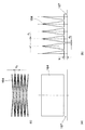
以上のように構成されたプリンタにおいて、本発明に係るインク貯留部の構造を採用した参考形態の貯留インクタンクを、図12を参照して説明する。なお、図12では、構成をわかりやすくにするために、便宜上、1色分のインク貯留部のみを図示している。多色の場合には、図4に示したように、ほぼ等しい構造のインク貯留部が複数個並んで設けられる。
【0075】
図12(a),図12(b)および図12(c)に示すように、貯留インクタンク160の筐体161には、一側面に、内部に連通された空気取り入れ口162が設けられ、底面の中央に、インク供給口165を有するインク供給管171が配置されており、インク供給口165から記録ヘッドにインクを供給し、外部から空気取り入れ口162を介して空気が取り入れられる。
【0076】
また、貯留インクタンク160の筐体161には、一側面に、筐体161内にインクを取り入れるためのインク取り入れ口170が設けられており、このインク取り入れ口170がシール部材178によって気密に封止されている。
【0077】
また、貯留インクタンク160の筐体161には、上面部に、通気路176が設けられている。この通気路176は、インク供給時に後述するインク貯留部166内に負圧を導入するためのもので、インク供給配管177によってインクが供給されて、インクの液面が多孔質部材175に到達したときに、インクの供給が自動的に停止する。シール部材178は、インク供給配管177が接続されたときに、筐体161内の気密性を確保する。
【0078】
筐体161内には、図12(a)に示すように、複数の薄厚体164が互いに間隔をあけて平行にそれぞれ配設されており、これら複数の薄厚体164の外周部が、複数の支持部材163に支持されて固定されている。各支持部材163は、筐体161内に、複数の薄厚体164の角部に臨む位置にそれぞれ設けられており、薄厚体164と筐体161の内壁との間に所定の間隔が確保されている。
【0079】
複数の薄厚体164は、略四角形をなしており、インクに対して充分な濡れ性を有する材料によって形成される、あるいは平板上に表面処理が施されている。そして、複数の薄厚体164間に隙間によってインク貯留部166が構成されている。貯留インクタンク160は、インク貯留部166にインクが充填されることで毛管力が発生し、この毛管力によってインクが保持されている。
【0080】
この毛管力は、水頭h[m]、インクの表面張力T[Nm]、インクの薄厚体に対する接触角θ、インク密度ρ[kg/m3]、重力加速度g[m/s2]、毛細管の半径r[m]とすれば、
h=2TCosθ/ρgr ・・・式1
式1によって表すことができる。
【0081】
また、この式1は、薄厚体の間隙寸法dで長さが間隙寸法dより十分長い平行平板の場合には、近似的に、
h=4TCosθ/ρgd ・・・式2
となる。
【0082】
したがって、例えば、t=0.03、cosθ=1、ρ=1063、g=9.8であれば、d=0.0001[m](=0.1[mm])のとき、h=115[mm]となる。
【0083】
同様に、薄厚体の間隙寸法dをパラメータとして算出すれば、表1に示すようになる。
【0084】
【表1】

記録ヘッドに印加すべき負圧は、記録ヘッドの仕様により異なるが、通常(−)0〜(−)200[mm]水頭程度である。当然、インク貯留タンク内のインクが持つ負圧は、記録ヘッドとインク貯留タンクとの高度差によって変動するため、この高度差分だけオフセットする必要がある。
【0086】
したがって、供給されるインクに求められる負圧は、望ましくはマイナス数十[mm]からマイナス200[mm]水頭である。この範囲より負圧が低い場合には、記録ヘッドの吐出口からのインク漏れを生じる虞がある。また、この範囲より負圧が高すぎた場合には、インク供給におけるインク切れや、不十分な供給のための印字の濃度の低下や吐出できないなどの問題を生じる。そして、この要求を満たすインク貯留部166の間隙寸法dは、表1に示した結果から、0.05[mm]以上0.5弱[mm]以下になる。
【0087】
一方、n個の薄厚体164の占有体積に対するインクの充填効率I[%]は、上述のインク貯留部66の間隙寸法dとの関係で表され、
I=(n−1)・d/{nt+(n−1)・d} ・・・式3
となり、インクの充填効率を上げるためには、薄厚体厚さtを0に近づければよい。
【0088】
薄厚体164の材質としては、インク中に分解物や添加物が溶出したり、インクと反応して反応生成物を生じたり、インクを取り込んで膨張したりしない物質を選択する必要がある。また上述したように、インク充填効率を考慮して、薄厚体を可能な限り薄くすることが望ましく、また薄くした場合であっても充分な機械的強度が確保されることが好ましい。
【0089】
このような要求を満たし、かつ安価な材料として、ステンレス薄厚体、薄いシートを容易に入手することが可能なポリプロピレンやポリエチレンやEVA(エチレン酢酸ビニル共重合体)等のオレフィン系や、PTFE(ポリテトラフルオロエチレン)等のテフロン系のプラスチックが用いられる。また、流れ性が良好であるため、薄肉厚のモールド成型が可能なポリサルフォン系のプラスチック等、インクの性質、組み立て性等から選択して採用できる。
【0090】
インク誘導部167は、薄厚体164とインク供給口165が配置された筐体161の内壁によって形成されている。インク誘導部167の毛管力は、インク貯留装置内に構成された毛管力を発生するいかなるなる部位よりも大きくなるように設定されている。薄厚体164の周りには、毛管力を発生しないバッファ168が、支持部材163によって幅aまたは幅cに形成される。このバッファ168は、例えば水を多く含んだインクが、物流中等の低温環境において凍結膨張した場合、この膨張分を吸収する空間として作用する。
【0091】
インクの凍結が解除された後、バッファ168のインクがインク貯留部166に戻るためには、バッファ168の毛管力が、インク貯留部166の毛管力よりも小さい必要がある。
【0092】
これらの条件を踏まえて、筐体161と薄厚体164のインクに対する濡れ性が同等であれば、上述の式より各間隙寸法dは、
b<d<(aまたはc) ・・・式4
を満たせばよい。
【0093】
図13に、インク貯留部166内のインクの流動状態を説明するための図を示す。インク貯留部166内のインクは、薄厚体164に対する濡れとインクの表面張力とによってメニスカス169を生じ、インク内部に負圧を発生する。そして、インクは、インク供給口165から記録ヘッドに供給されることで消費され、毛管力の力関係に応じて薄厚体164から順序よく消費される。インク供給口165近傍のインク誘導部167には、インク貯留部166より大きい毛管力を発生するため、インクが優先的に充填される。このため、プリンタにインクを供給する際には、気泡等が取り込まれずに安定されている。
【0094】
一方、インクの流動抵抗としては、インクの薄厚体164に対するせん断応力が支配的であり、その他の抵抗成分がほとんど発生しない。したがって、本参考形態の貯留インクタンクは、特に、短時間に大量のインクを消費する記録速度が比較的高速なインクジェットプリンタに適している。
【0095】
(第1の実施形態)
図14に、本発明の構造を採用した第1の実施形態の貯留インクタンクを示す。本実施形態の貯留インクタンクは、各部の構成および機能が、参考形態の貯留インクタンクと同一であるが、信頼性を更に向上させるための工夫が追加されている。なお、本実施形態の貯留インクタンクにおいて、便宜上、上述した参考形態の貯留インクタンクと同一部材には同一符号を付して説明を省略する。
【0096】
図14に示すように、インク貯留部166は、インク供給口165から離間するに従って、間隙寸法dが次第に大きくなるようなテーパー状に形成されている。
【0097】
図15に、上述したテーパー形状をなすインク貯留部166を形成するために用いられる薄厚体164の形状を説明するための図を示す。図15に示すように、各薄厚体164は、上端側に向かって間隙寸法dが次第に大きくなるとともに、筐体161の側面に臨む側端側に向かって間隙寸法dが、次第に大きくされている。
【0098】
このインク貯留部166は、テーパー形状に形成されるによって、インク貯留部166が発生する毛管力は、インク供給口165に近づくに従って大きくなり、インク供給口165にインクを更に確実に導くことができる。
【0099】
また、インク誘導部167に隣接する位置には、複数の溝180が設けられている。これら溝180は、筐体161内の底面に設けられており、これらの溝180が持つ毛管力が、インク誘導部167の毛管力と同等またはそれ以上に設定されている。このような毛管力の関係を確保することによって、インク供給口165にインクを確実に誘導することが可能になる。
【0100】
図16に、インク誘導部167に隣接して設けられた溝180の一例の平面図を示す。図16に示すように、溝180は、インク供給口165を中心とする放射線状にそれぞれ形成されており、インク誘導部167全体における毛管力が、各溝180の幅d4によって調整される。したがって、本実施形態では、図15に示すように、各部の毛管力の関係を適正に保つために、
(d1,d3)>d2>b>d4 ・・・式5
を満たすように構成されている。
【0101】
最後に、第2の実施形態のインク貯留タンクについて図面を参照して説明する。図17に、第2の実施形態のインク貯留タンクを示す。なお、本実施形態の貯留インクタンクにおいて、便宜上、上述した参考形態の貯留インクタンクと同一部材には同一符号を付して説明を省略する。
【0102】
図17に示すように、この貯留インクタンクは、筐体内に、略波形状をなす薄厚体181が配設されている。
【0103】
薄厚体181は、図18に示すように、板材によって略波形状に形成されており、水平方向に対して波形をなすように配置されている。各薄厚体181は、波形の凹凸を互いに一致させて配置されており、波形状のインク貯留部が構成されている。
【0104】
このように、薄厚体181は、波形状に形成されることで、特に、波形方向に直交する縦方向の機械的強度が増加するため、薄厚体181の厚さを極めて薄く形成しても、良好な形状が確保される。その結果、この薄厚体181によれば、筐体内に配設する薄厚体181の個数を増やすことで、インク貯留部の空間を増加させて、インクの貯留効率を向上することができる。
【0105】
上述したように、プリンタが備える貯留インクタンクによれば、互いに間隙をあけて設けられた複数の薄厚体を有するインク貯留部と、インク供給口近傍の毛管力がインク貯留部の毛管力よりも大きくなるようにインク貯留部の一端と筐体の内壁との間に間隙をあけた液体誘導部とを備えることによって、比較的廉価に製造することが可能な構成で、インクに対する化学的な安定性を確保し、貯留インクタンクの姿勢差に限らず低い流路抵抗で負圧を発生させ、インクを安定的に供給することができる。したがって、このプリンタによれば、記録媒体Sの記録品質を廉価に向上することができる。
【0106】
また、本発明に係るインク貯留タンクは、インク貯留部内に複数の薄厚体が設けられ、薄厚体の下端側にインク誘導部が設けられる構成であれば、上述した構成に限らず、例えば図3や図8に示した構成が適用されてもよいことは勿論である。
【0107】
なお、本発明は、液体の吐出を行わせるために利用されるエネルギとして熱エネルギを発生するエネルギ発生手段(例えば電気熱変換体やレーザ光等)を備え、この熱エネルギにより液体の状態変化を生起させるインクジェット方式の液体吐出ヘッドやヘッドカートリッジまたは記録装置において優れた効果が得られる。すなわち、インクジェット方式によれば、プリントの高密度化および高精細化が達成できる。
【0108】
その代表的な構成や原理については、例えば米国特許第4723129号明細書や、米国特許第4740796号明細書等に開示されている基本的な原理を用いて行うものが好ましい。この方式は、いわゆるオンデマンド型およびコンティニュアス型の何れにも適用可能であるが、特にオンデマンド型の場合には、液体が保持されているシートや流路に対応して配置される電気熱変換体に、プリント情報に対応した核沸騰を越える急速な温度上昇を与える少なくとも1つの駆動信号を印加することにより熱エネルギを発生させ、液体吐出ヘッドの熱作用面に膜沸騰を生じさせ、結果的にこの駆動信号に一対一で対応した液体内の気泡を形成できるので有効である。この気泡の成長および収縮により、吐出口を介して液体を吐出させ、少なくとも1つの液滴を形成する。この駆動信号をパルス形状とすると、即時適切に気泡の成長収縮が行われるので、特に応答性に優れた液体の吐出が達成でき、より好ましい。このパルス形状の駆動信号としては、米国特許第4463359号明細書や、米国特許第4345262号明細書等に記載されているようなものが適している。
【0109】
なお、上記熱作用面の温度上昇率に関する発明の米国特許第4313124号明細書に記載されている条件を採用することで、さらに優れたプリントを行うことができる。
【0110】
液体吐出ヘッドの構成としては、上述の各明細書に開示されているような吐出口と液路と電気熱変換体とを組み合せた構成(電気熱変換体が液路に沿って配置された直線状液路または電気熱変換体が液路を挟んで吐出口と正対する直角液路)の他に、熱作用部が屈曲する領域に配置されている構成を開示する米国特許第4558333号明細書や、米国特許第4459600号明細書等を用いた構成も本発明に含まれる。加えて、複数の電気熱変換体に対し、共通するスリットを電気熱変換体の吐出部とする構成を開示する特開昭59−123670号公報や、熱エネルギの圧力波を吸収する開孔を吐出部に対応させる構成を開示した特開昭59−138461号公報に基づいた構成としても、本発明の効果は有効である。すなわち、液体吐出ヘッドの形態がどのようなものであっても、本発明によれば記録を確実に効率良く行うことができるようになる。
【0111】
記録装置がプリントできる記録媒体Sの最大幅に対応した長さを有するフルラインタイプの液体吐出ヘッドに対しても本発明は有効に適用できる。このような液体吐出ヘッドとしては、複数の液体吐出ヘッドの組み合わせによってその長さを満たす構成や、一体的に形成された1個の液体吐出ヘッドとしての構成の何れでもよい。
【0112】
上述した実施形態のようなシリアルタイプのものでも、走査移動するキャリッジに対して一体的に固定された液体吐出ヘッドや、キャリッジに対して交換可能に装着されることでキャリッジとの電気的な接続や装置本体からの液体の供給が可能となる交換自在のチップインタイプのヘッドカートリッジ、あるいは液体吐出ヘッド自体に、液体を貯溜するタンクが一体的または着脱可能に設けられるヘッドカートリッジを用いた場合にも本発明は有効である。
【0113】
本発明の記録装置の構成としては、液体吐出ヘッドから吐出される液体の吐出状態を適正にするための回復手段や、予備的な補助手段等を付加することが、本発明の効果を一層安定させることができるので、好ましい。これらを具体的に挙げれば、液体吐出ヘッドに対するキャッピング手段、クリーニング手段、加圧あるいは吸引手段、電気熱変換体やこれとは別の加熱素子あるいはこれらの組み合わせを用いて加熱を行う予備加熱手段、記録動作とは別に吐出を行う予備吐出手段等を挙げることができる。
【0114】
搭載される液体吐出ヘッドの種類や個数についても、例えば単色のインクに対応して1個のみが設けられたものの他、プリント色や濃度(明度)を異にする複数種のインクに対応して複数個設けられるものであってもよい。すなわち、例えば、記録装置のプリントモードとしては、黒色等の主流色のみの記録モードだけではなく、液体吐出ヘッドを一体的に構成するか、複数個の組み合わせによるか何れでもよいが、異なる色の複色カラーまたは混色によるフルカラーの各記録モードの少なくとも1つを備えた記録装置にも本発明は極めて有効である。この場合、記録媒体Sの種類や記録モードに応じてインクのプリント性を調整するための処理液(プリント性向上液)を専用あるいは共通の液体吐出ヘッドから記録媒体Sに吐出することも有効である。
【0115】
本発明に係る記録装置の形態としては、例えば、コンピュータ等の情報処理機器の画像出力端末として用いられるものの他、リーダ等と組み合せた複写装置、さらには送受信機能を有するファクシミリ装置や捺染装置、あるいはエッチング装置の形態を採るもの等であってもよい。また、記録媒体としては、シート状あるいは長尺の紙やフィルム、布帛、あるいは板状をなす木材や皮革,石材,樹脂,ガラス,金属等の他に、3次元立体構造物等が適用される。
【0116】
【発明の効果】
上述したように本発明に係る液体貯留装置によれば、液体貯留室内に対して毛管力を発生するように間隙をおいて複数の薄厚体を、液体供給口が設けられた内壁に複数の薄板の端部が面するように配備した液体貯留部と、液体貯留部を形成する複数の薄板の端部と液体貯留室の液体供給口が設けられた内壁との間に、液体貯留部の毛管力よりも大きな毛管力を発生する間隙で構成されて、液体供給口に連通する誘導部と、液体供給口が設けられた内壁に、誘導部の毛管力よりも大きな毛管力を発生し、かつ液体供給口に向かう複数の溝とを備えることによって、比較的廉価に製造することが可能な構成で、液体に対して化学的に安定であり、液体タンクの姿勢差に限らず低い流路抵抗で負圧を発生させ、液体を安定的に供給することができる。
【図面の簡単な説明】
【図1】本発明に係るシリアルタイプのインクジェットプリンタを示す断面図である。
【図2】前記インクジェットプリンタを示すA−A断面図である。
【図3】前記インクジェットプリンタが備えるヘッドカートリッジを示す斜視図である。
【図4】前記ヘッドカートリッジを示す分解斜視図である。
【図5】前記インクジェットプリンタの記録中の状態を示す縦断面図である。
【図6】前記インクジェットプリンタの電源オフまたは待機中の状態を示す縦断面図である。
【図7】前記インクジェットプリンタにおけるインク補給中の状態を示す縦断面図である。
【図8】他のインクジェットプリンタにおける記録中の状態を示す横断面図である。
【図9】前記他のインクジェットプリンタが備える貯留インクタンクを示す側面図である。
【図10】前記他のインクジェットプリンタにおける電源オフまたは待機中の状態を示す横断面図である。
【図11】前記他のインクジェットプリンタにおけるインク補給中の状態を示す横断面図である。
【図12】参考形態のインク貯留部を説明するための図である。
【図13】前記インク貯留部内でインクが流動する状態を説明するための図である。
【図14】第1の実施形態のインク貯留部を説明するための図である。
【図15】前記インク貯留部を構成する薄厚体を説明するための図である。
【図16】インク誘導部に隣接する溝を示す平面図である。
【図17】第2の実施形態のインク貯留部を説明するための図である。
【図18】前記インク貯留部を構成する薄厚体を示す斜視図である。
【図19】従来のバネ袋方式のインク貯留装置の構造を説明するための模式図である。
【図20】従来の調圧弁付き袋方式のインク貯留装置の構造を説明するための模式図である。
【図21】従来のスポンジ方式のインク貯留装置の構造を説明するための模式図である。
【図22】従来の積層毛管力方式のインク貯留装置の構造を説明するための模式図である。
【符号の説明】
1 給送部
2 記録部
3 インク補給部
4 カバー
4a 挿入口
4b 排出口
6 側板
7 コイルばね
8 載置台
9 給送ローラ
10 分離機構
11 ガイド部材
12 フォトセンサ
13 搬送ローラ
14 搬出ローラ
15,16 ガイド軸
17 プーリ
18 ベルト
19 キャリッジ
20(20Y,20M,20C,20Bk) 貯溜インクタンク
20a インクジェットヘッド(記録ヘッド)
20b インク取り入れ口
21a 配管
21f 連通孔
22 補給インクタンク
23 操作ボタン
24 電気配線基板
25 制御回路部
31 補給用吸引ポンプ
41 インク貯留部
42 インク供給口
43 共通インク室
44 吐出口
44a 吐出口面
48 多孔質部材
49〜52 通気路
53 共通吸引口
54 キャップ部材
55 導管
55a 連通孔
60 天板
61 供給キャップ部材
64 通気孔
71 回復処理用吸引ポンプ
161 筐体
162 空気取り入れ口
163 支持部材
164 薄厚体
165 インク供給口
166 インク貯留部
167 インク誘導部
168 バッファ
169 メニスカス
170 インク取り入れ口
171 インク供給管
175 多孔質部材
176 通気路
177 インク供給配管
178 シール部材
180 溝
181 薄厚体
221 袋
222 コイルバネ
223 インク
224 供給口
225 バネの力
230 筐体
231 調圧弁
232 内部空気
233 外部空気
240 筐体
241 スポンジ
242 通気孔
243 インク供給口
250 筐体
251 薄板
252 インク供給口
253 インク貯留部
255 毛管体[0001]
BACKGROUND OF THE INVENTION
The present invention relates to a liquid storage device provided in a recording apparatus that records, for example, by ejecting ink onto recording paper or the like, and more particularly to a liquid storage device that uses a gas-liquid separation member to supply a liquid such as ink.
[0002]
[Prior art]
2. Description of the Related Art Conventionally, an ink jet recording apparatus includes an ink jet recording head that ejects ink droplets, a main tank that stores ink to be supplied to the ink jet recording head, and a sub tank that stores ink supplied from the main tank. Things are known.
[0003]
In this type of ink jet recording apparatus, many ink supply mechanisms for supplying ink to the ink jet recording head have been proposed and put into practical use. In order to supply ink to the ink jet recording head, the capillary force of the nozzle of the ink jet recording head itself is used, so that external force such as a pump is usually not required. Therefore, a mechanism for pumping ink from the sub tank (stored ink tank) to the ink jet recording head is not necessary except for a special example. On the other hand, in order to stably and continuously eject ink droplets from the nozzles of the inkjet recording head, it is necessary to apply a very weak negative pressure (−) 30 [Pa] to (−) 2000 [Pa]. This is an important issue in designing an ink jet recording apparatus.
[0004]
In order to realize this, many attempts have been made to provide a negative pressure generating mechanism in an ink storage device having a storage ink tank. The structure of a conventional ink storage device will be described with reference to the drawings.
[0005]
FIG. 19 shows a schematic diagram of the structure of an ink storage device employing a spring bag system. As shown in FIG. 19, in this ink storage device, in order to generate a negative pressure, a
[0006]
FIG. 20 shows a schematic diagram of the structure of an ink storage device that employs a bag system with a regulating valve. As shown in FIG. 20, in this ink storage device, a
[0007]
FIG. 21 is a schematic diagram of the structure of an ink storage device that employs a currently mainstream sponge. As shown in FIG. 21, in this ink storage device, a
[0008]
However, a sponge manufactured by a general sponge manufacturing method is insufficient in density, and thus needs to be compressed to some extent. As a result, the sponge method has a disadvantage that the use efficiency of the sponge ink is deteriorated, and generally only about 70% of the sponge volume can be filled with ink.
[0009]
In general, the portion of the ink jet recording apparatus that comes into contact with ink is made of stainless steel in the case of a metal material, and made of polypropylene, polyethylene, fluororesin, or the like in the case of a resin material. Such a contact portion of the ink may come into contact with the ink so that a very small amount of decomposition products and additives are dissolved in the ink. Moreover, many commercially available sponges are made of urethane resin and have a relatively low chemical stability. For this reason, in recent years, polypropylene sponges that are chemically more stable have been employed.
[0010]
However, since a porous body such as a sponge has a large area in contact with ink, chemical reaction with the ink, additives or the like elute in the ink, and a large amount of product adversely affects the vicinity of the nozzle. There are many cases. On the other hand, various types of ink are used to expand the application of inkjet recording devices, but the chemical stability of the sponge becomes a problem. As a result, it is unavoidable to change the components of the ink to improve the chemical stability. There was also a lot of need to improve and instead reduce physical properties.
[0011]
Furthermore, the ink carrier produced by compressing the urethane resin sponge as described above or polypropylene or polyethylene fiber has a relatively large density distribution. Therefore, when the ink refill is repeated, air bubbles are formed in the density structure. Is embraced and the ink filling rate gradually decreases. This phenomenon is caused by the fact that when the ink is refilled, the capillary force of the dense portion of the ink holding member is relatively large, so that the ink is filled first, and the ink is not supplied to the rough portion, and as a result, air bubbles are left behind. Because of. Once generated, air bubbles tend to remain as bubbles even when ink is sucked out, and by repeating refilling, the size and quantity of bubbles increase and the filling rate decreases.
[0012]
FIG. 22 shows another configuration having a function equivalent to that of a sponge that serves as both ink storage and generation of negative pressure. As shown in FIG. 22, a configuration is disclosed in which ink is stored by a plurality of
[0013]
However, in order to reliably take out the ink from the
[0014]
[Patent Document 1]
JP-A-4-179553
[Patent Document 2]
JP-A-3-139562
[0015]
[Problems to be solved by the invention]
As described above, in an ink jet recording apparatus, the ink jet recording apparatus is chemically stable with respect to ink by an inexpensive manufacturing method, and generates a negative pressure with a low flow path resistance regardless of the posture difference of the stored ink tank. There is a need for an ink storage device that stably supplies ink.
[0016]
In particular, in an ink jet recording apparatus that performs recording while refilling ink in a subtank that temporarily stores ink supplied from a main tank, a phenomenon in which the filling rate of ink that can be filled in the subtank decreases by repeating refilling. Is a fatal problem.
[0017]
Therefore, the present invention has a configuration that can be manufactured at a relatively low cost, ensures chemical stability with respect to the liquid, generates a negative pressure with a low flow resistance, not limited to a difference in the posture of the liquid tank, An object of the present invention is to provide a liquid storage device capable of stably supplying the liquid.
[0018]
[Means for Solving the Problems]
In order to achieve the above-described object, the present invention includes the following various aspects.
[0019]
(1) The liquid storage apparatus according to the present inventionStorageDoLiquid storage chamberAnd thisLiquid storage chamberNegative pressureThe source is connectedBy the negative pressure introduction part and the negative pressure introduced from this negative pressure introduction partLiquid storage chamberA liquid intake for taking in liquid, Liquid storage chamberProvided inLiquid storage chamberWithinStorageA liquid supply port for supplying the liquid and a gas-liquid separation member that is provided in the negative pressure introducing portion and allows only gas to pass therethrough.In this liquid storage device, the liquid stored in the liquid storage chamber can be led out from the liquid supply port.Also,The liquid storage device is a liquid in which a plurality of thin plates are arranged at intervals so as to generate a capillary force in the liquid storage chamber, and an end of the plurality of thin plates faces an inner wall provided with a liquid supply port. A gap that generates a capillary force that is greater than the capillary force of the liquid reservoir between the reservoir and the ends of the plurality of thin plates that form the liquid reservoir and the inner wall provided with the liquid supply port of the liquid reservoir. A plurality of grooves configured to generate a capillary force larger than the capillary force of the guide portion on the inner wall provided with the liquid supply port, and to the liquid supply port; An air intake for introducing external air into the liquid storage chamber.
[0020]
(2) The liquid supply apparatus according to the present invention supplies the liquidStorageDoLiquid storage chamberWhen,Liquid storage chamberNegative pressureThe source is connectedBy the negative pressure introduction part and the negative pressure introduced from the negative pressure introduction partLiquid storage chamberA liquid intake for taking in liquid, Liquid storage chamberProvided inLiquid storage chamberWithinStorageA liquid supply port for supplying the liquid, a gas-liquid separation member that is provided in the negative pressure introduction part and allows only gas to pass therethrough;A liquid storage section in which a plurality of thin plates are arranged at intervals so as to generate a capillary force in the liquid storage chamber, and an inner wall provided with a liquid supply port faces an end portion of the plurality of thin plates; A liquid supply port constituted by a gap that generates a capillary force larger than the capillary force of the liquid storage portion between the end portions of the plurality of thin plates forming the storage portion and the inner wall provided with the liquid supply port of the liquid storage chamber A guide section that communicates directly with the liquid supply port, a capillary force greater than the capillary force of the guide section on the inner wall where the liquid supply port is provided, and a plurality of grooves toward the liquid supply port, and external air is introduced into the liquid storage chamber An air intake portA liquid tank,
Liquid storage chamberSuck in the air and apply negative pressureNegativePressure generating means,
Is provided.
[0021]
According to the liquid storage device of the present invention configured as described above, a plurality of thin filmsBoardThe space | interval which faced without contact | abutting mutually acts as a liquid storage part, and the liquid stored by this liquid storage part is hold | maintained by the capillary force of the liquid itself. Moreover, according to the liquid storage device of the present invention,, InvitationSince the capillary force in the vicinity of the liquid supply port is made larger by the guide portion than the capillary force of the liquid storage portion, the liquid held in the liquid storage portion is supplied from the liquid supply port to, for example, a liquid discharge head or the like. . According to the liquid storage device of the present invention, a plurality of thin filmsBoardSince only the liquid is held and the liquid is supplied satisfactorily, the structure can be manufactured at a relatively low cost. In addition, according to the liquid supply apparatus of the present invention, chemical stability with respect to the liquid is ensured, and the negative pressure is generated not only with the difference in posture of the liquid tank but with a low flow path resistance, so that the liquid is stably supplied It becomes possible.
[0022]
(3) The liquid according to (1) or (2), wherein a groove that generates a capillary force larger than the capillary force of the liquid guiding part is formed in a position adjacent to the liquid guiding part on the inner wall of the housing part. Storage device.
[0023]
(4) The liquid storage device according to any one of (1) to (3), wherein the liquid storage unit gradually increases as the distance between the previous thin bodies increases from the liquid guide unit.
[0024]
(5) The liquid storage device according to any one of (1) to (4), wherein the interval between the plurality of thin bodies is 0.05 mm or more and 0.5 mm or less.
[0025]
(6) The liquid storage device according to any one of (1) to (5), wherein the capillary force of the liquid storage unit is 30 Pa or more and 2000 Pa or less.
[0026]
(7) The liquid storage device according to any one of
[0027]
(8) The liquid storage device according to any one of
[0028]
(9) The liquid storage device according to any one of (1) to (6), wherein the gas-liquid separation member is a gas permeable membrane made of a porous resin material. Examples of the resin porous material include PTFE (polytetrafluoroethylene) or a similar material.
[0029]
(10) The liquid storage device according to any one of (7) to (9), wherein the gas-liquid separation member is subjected to a liquid repellent treatment.
[0030]
(11) A recording apparatus that includes the liquid storage device according to any one of (1) to (10), and that records ink by discharging ink with a recording head.
[0031]
DETAILED DESCRIPTION OF THE INVENTION
Hereinafter, specific embodiments of the present invention will be described with reference to the drawings.
[0032]
(referenceForm)
FIG. 1 and FIG.referenceIt is sectional drawing which shows schematic structure of the inkjet printer of a form. BookreferenceThe ink jet printer according to the embodiment is one to which a serial scan method in which the ink jet head moves in the main scanning direction is applied.
[0033]
As shown in FIG. 1, an ink jet printer (hereinafter simply referred to as a printer) records a character, an image, and the like by ejecting ink onto the recording medium S and a
[0034]
The
[0035]
The
[0036]
The printer also includes a pair of
[0037]
As shown in FIGS. 1 and 2, the
[0038]
The carriage 19 is moved by an arrow m in FIG.1, M2It is guided so as to be movable in the main scanning direction (width direction of the recording medium S). The carriage 19 is moved in the main scanning direction by a driving force transmitted from a carriage motor (not shown) via a
[0039]
The
[0040]
BookreferenceThe printer according to the embodiment includes a head cartridge in which the
[0041]
As shown in FIG. 6, the outer periphery of the
[0042]
FIG. 6 shows a state in which the
[0043]
FIG. 7 shows a state in which ink is supplied to the stored
[0044]
The
[0045]
At the time of ink replenishment, the air in the stored
[0046]
Since the rising speed of the ink level depends on the suction force of the
[0047]
After the ink suction operation is completed, the printer returns to the state shown in FIG. 6 or 5 by moving the
[0048]
FIG. 3 is a perspective view of the head cartridge, and FIG. 4 is an exploded perspective view of the head cartridge.
[0049]
In other words, the
[0050]
BookreferenceIn the embodiment, the
[0051]
The
[0052]
The
[0053]
Examples of the material of the
[0054]
The
[0055]
As shown in FIGS. 3 and 4, a
[0056]
Mentioned abovereferenceIn the embodiment, the
[0057]
Other like thisreferenceThe printer and storage ink tank of the embodiment will be described with reference to the drawings. For convenience, the same members as those of the printer described above are denoted by the same reference numerals and description thereof is omitted.
[0058]
As shown in FIG. 8, this printer is provided with a
[0059]
The
[0060]
An
[0061]
BookreferenceIn the case of the embodiment, the
[0062]
A hollow projecting
[0063]
The
[0064]
The
[0065]
Further, a
[0066]
The recording medium S is moved by an arrow m indicating the main scanning direction by a transport mechanism (not shown).1And m2It is conveyed in the sub-scanning direction that intersects the direction. Images and the like are sequentially formed on the recording medium S by repeating the main scanning of the
[0067]
During the recording operation, the
[0068]
As shown in FIG. 10, when the
[0069]
The
[0070]
During the ink supply operation, as shown in FIG. 11, the
[0071]
When replenishing ink into the stored
[0072]
After the ink replenishment operation is completed, the printer returns to the state shown in FIG. 10 or FIG. 8 by moving the
[0073]
The
[0074]
In the printer configured as described above, the structure of the ink reservoir according to the present invention is adopted.referenceThe storage ink tank of the form will be described with reference to FIG. In FIG. 12, for the sake of simplicity, only one color ink storage section is shown for convenience. In the case of multiple colors, as shown in FIG. 4, a plurality of ink storage portions having substantially the same structure are provided side by side.
[0075]
As shown in FIGS. 12 (a), 12 (b), and 12 (c), the
[0076]
In addition, the
[0077]
The
[0078]
In the
[0079]
The plurality of
[0080]
This capillary force includes a water head h [m], an ink surface tension T [Nm], a contact angle θ with respect to a thin ink body, and an ink density ρ [kg / m.Three], Gravitational acceleration g [m / s2], If the capillary radius r [m],
h = 2TCosθ /
It can be represented by
[0081]
Further, this
h = 4TCosθ /
It becomes.
[0082]
Therefore, for example, if t = 0.03, cos θ = 1, ρ = 1063, and g = 9.8, when d = 0.0001 [m] (= 0.1 [mm]), h = 115 [mm].
[0083]
Similarly, when the gap dimension d of the thin body is calculated as a parameter, it is as shown in Table 1.
[0084]
[Table 1]
Although the negative pressure to be applied to the recording head varies depending on the specifications of the recording head, it is generally about (−) 0 to (−) 200 [mm] water head. Naturally, the negative pressure of the ink in the ink storage tank fluctuates due to the height difference between the recording head and the ink storage tank, so it is necessary to offset by this height difference.
[0086]
Therefore, the negative pressure required for the supplied ink is preferably minus several tens [mm] to minus 200 [mm] water head. When the negative pressure is lower than this range, ink leakage from the ejection port of the recording head may occur. Further, if the negative pressure is too high in this range, problems such as ink shortage in ink supply, a decrease in print density due to insufficient supply, and inability to discharge occur. The gap dimension d of the
[0087]
On the other hand, the ink filling efficiency I [%] with respect to the occupied volume of the n
I = (n−1) · d / {nt + (n−1) · d}
Therefore, in order to increase the ink filling efficiency, the thin body thickness t should be close to zero.
[0088]
As the material of the
[0089]
As an inexpensive material that satisfies these requirements, olefinic materials such as polypropylene, polyethylene, EVA (ethylene vinyl acetate copolymer), etc., and PTFE (polyethylene), which can easily obtain thin stainless steel sheets and thin sheets, can be obtained. Teflon plastic such as tetrafluoroethylene is used. In addition, since the flowability is good, it can be selected and adopted from the properties of the ink, assemblability, etc., such as polysulfone plastic that can be molded with a thin wall thickness.
[0090]
The
[0091]
In order for the ink in the
[0092]
Based on these conditions, if the wettability with respect to the ink of the
b <d <(a or c)
Should be satisfied.
[0093]
FIG. 13 is a diagram for explaining the flow state of ink in the
[0094]
On the other hand, as the flow resistance of the ink, the shear stress on the
[0095]
(No.1Embodiment)
FIG. 14 shows a first example adopting the structure of the present invention.1The storage ink tank of embodiment is shown. The storage ink tank of this embodiment has a configuration and function of each part.referenceAlthough it is the same as the storage ink tank of a form, the device for further improving reliability is added. In the storage ink tank of the present embodiment, the above-mentioned is described for convenience.referenceThe same members as those of the storage ink tank of the embodiment are denoted by the same reference numerals, and description thereof is omitted.
[0096]
As shown in FIG. 14, the
[0097]
FIG. 15 is a view for explaining the shape of the
[0098]
Since the
[0099]
A plurality of
[0100]
FIG. 16 shows a plan view of an example of the
(D1, DThree)> D2> B> dFour ... Formula 5
It is configured to satisfy.
[0101]
Finally, the second2The ink storage tank of this embodiment will be described with reference to the drawings. In FIG.2The ink storage tank of embodiment is shown. In the storage ink tank of the present embodiment, the above-mentioned is described for convenience.referenceThe same members as those of the storage ink tank of the embodiment are denoted by the same reference numerals, and description thereof is omitted.
[0102]
As shown in FIG. 17, the stored ink tank has a
[0103]
As shown in FIG. 18, the
[0104]
Thus, since the
[0105]
As described above, according to the storage ink tank provided in the printer, the ink storage portion having a plurality of thin bodies provided with a gap therebetween, and the capillary force in the vicinity of the ink supply port is greater than the capillary force of the ink storage portion. By providing a liquid guide part with a gap between one end of the ink storage part and the inner wall of the housing so as to be large, it can be manufactured at a relatively low cost, and is chemically stable against ink. Therefore, not only the posture difference of the stored ink tank but also a negative pressure can be generated with a low flow resistance, and ink can be supplied stably. Therefore, according to this printer, the recording quality of the recording medium S can be improved at a low cost.
[0106]
Further, the ink storage tank according to the present invention is not limited to the above-described configuration as long as a plurality of thin bodies are provided in the ink storage section and the ink guiding section is provided on the lower end side of the thin body. Of course, the configuration shown in FIG. 8 may be applied.
[0107]
The present invention includes energy generating means (for example, an electrothermal converter, a laser beam, etc.) that generates thermal energy as energy used for discharging the liquid, and changes the state of the liquid by this thermal energy. An excellent effect can be obtained in an ink jet type liquid discharge head, a head cartridge, or a recording apparatus to be generated. That is, according to the ink jet system, it is possible to achieve high density and high definition of prints.
[0108]
As the typical configuration and principle thereof, those carried out using the basic principle disclosed in, for example, US Pat. No. 4,723,129 and US Pat. No. 4,740,796 are preferable. This method can be applied to both a so-called on-demand type and a continuous type. In particular, in the case of the on-demand type, an electric circuit arranged corresponding to a sheet or a channel holding a liquid is used. Applying at least one drive signal that gives a rapid temperature rise exceeding the nucleate boiling corresponding to the print information to the thermal converter to generate thermal energy, causing film boiling on the heat acting surface of the liquid discharge head, As a result, it is effective because bubbles in the liquid corresponding to the drive signals on a one-to-one basis can be formed. Due to the growth and contraction of the bubbles, the liquid is discharged through the discharge port to form at least one droplet. It is more preferable that the drive signal has a pulse shape, since the bubble growth and contraction is performed immediately and appropriately, and thus it is possible to achieve liquid discharge with particularly excellent responsiveness. As this pulse-shaped drive signal, those described in US Pat. No. 4,463,359, US Pat. No. 4,345,262, and the like are suitable.
[0109]
Further excellent printing can be performed by adopting the conditions described in U.S. Pat. No. 4,313,124 of the invention relating to the temperature rise rate of the heat acting surface.
[0110]
As a configuration of the liquid discharge head, a configuration in which an ejection port, a liquid path, and an electrothermal converter as disclosed in each of the above-described specifications are combined (a straight line in which the electrothermal converter is disposed along the liquid path). US Pat. No. 4,558,333 which discloses a configuration in which the heat acting part is disposed in a region where the heat acting part is bent in addition to the liquid passage or the electrothermal transducer which is opposed to the discharge port across the liquid passage) In addition, configurations using US Pat. No. 4,459,600 are also included in the present invention. In addition, for a plurality of electrothermal transducers, Japanese Patent Laid-Open No. 59-123670 that discloses a configuration in which a common slit is used as a discharge portion of the electrothermal transducer, or an opening that absorbs a pressure wave of thermal energy is provided. The effect of the present invention is also effective as a configuration based on Japanese Patent Application Laid-Open No. 59-138461 which discloses a configuration corresponding to the discharge unit. That is, regardless of the form of the liquid discharge head, according to the present invention, recording can be performed reliably and efficiently.
[0111]
The present invention can also be effectively applied to a full-line type liquid discharge head having a length corresponding to the maximum width of the recording medium S that can be printed by the recording apparatus. As such a liquid discharge head, either a configuration satisfying the length by a combination of a plurality of liquid discharge heads or a configuration as a single liquid discharge head formed integrally may be used.
[0112]
Even in the serial type as in the above-described embodiment, the liquid discharge head that is integrally fixed to the carriage that is moved by scanning, or the electrical connection with the carriage by being exchangeably attached to the carriage When a replaceable chip-in type head cartridge that can supply liquid from the main body of the apparatus or a head cartridge in which a liquid storage tank is provided integrally or detachably in the liquid discharge head itself is used. The present invention is also effective.
[0113]
As a configuration of the recording apparatus of the present invention, it is possible to further stabilize the effect of the present invention by adding a recovery means for making the discharge state of the liquid discharged from the liquid discharge head appropriate or a preliminary auxiliary means. This is preferable. Specific examples thereof include a capping unit, a cleaning unit, a pressurizing or suction unit for the liquid discharge head, a preheating unit for heating using an electrothermal converter, a heating element different from this, or a combination thereof, In addition to the recording operation, a preliminary discharge unit that discharges can be used.
[0114]
As for the type and number of liquid discharge heads to be mounted, for example, only one corresponding to a single color ink is provided, and also corresponding to a plurality of types of inks having different print colors and densities (lightness). A plurality of them may be provided. That is, for example, the printing mode of the printing apparatus is not limited to a printing mode of only a mainstream color such as black, but may be configured integrally with a liquid discharge head or a combination of a plurality of different colors. The present invention is extremely effective for a recording apparatus having at least one of multicolor or mixed color full color recording modes. In this case, it is also effective to eject a processing liquid (printability improving liquid) for adjusting the printability of ink according to the type of the recording medium S and the recording mode from the dedicated or common liquid ejection head to the recording medium S. is there.
[0115]
As a form of the recording apparatus according to the present invention, for example, in addition to those used as image output terminals of information processing equipment such as computers, a copying apparatus combined with a reader or the like, a facsimile apparatus or a textile printing apparatus having a transmission / reception function, or The thing etc. which take the form of an etching apparatus may be sufficient. As the recording medium, a three-dimensional structure or the like is applied in addition to a sheet or long paper, a film, a fabric, or a plate-like wood, leather, stone, resin, glass, metal, or the like. .
[0116]
【The invention's effect】
As described above, according to the liquid storage device of the present invention,Liquid storage chamberWithinTo generate capillary force againstGapLeaveMultiple thin bodies, Deployed so that the ends of multiple thin plates face the inner wall where the liquid supply port is providedA liquid reservoir;Between the end portions of a plurality of thin plates forming the liquid storage portion and the inner wall provided with the liquid supply port of the liquid storage chamber,Greater than the capillary force of the liquid reservoirIt is composed of a gap that generates a capillary force and communicates with the liquid supply portWith inductionA plurality of grooves that generate a capillary force larger than the capillary force of the guide portion on the inner wall provided with the liquid supply port and that are directed to the liquid supply port;With a configuration that can be manufactured at a relatively low cost, it is chemically stable with respect to the liquid, generates a negative pressure with a low flow path resistance, not limited to the difference in attitude of the liquid tank, It can be supplied stably.
[Brief description of the drawings]
FIG. 1 is a cross-sectional view showing a serial type ink jet printer according to the present invention.
FIG. 2 is a cross-sectional view taken along the line AA showing the ink jet printer.
FIG. 3 is a perspective view showing a head cartridge provided in the ink jet printer.
FIG. 4 is an exploded perspective view showing the head cartridge.
FIG. 5 is a longitudinal sectional view showing a state during recording by the ink jet printer.
FIG. 6 is a longitudinal sectional view showing a state where the ink jet printer is turned off or in a standby state.
FIG. 7 is a vertical cross-sectional view showing a state during ink supply in the ink jet printer.
FIG. 8 is a cross-sectional view showing a state during recording in another ink jet printer.
FIG. 9 is a side view showing a stored ink tank provided in the other ink jet printer.
FIG. 10 is a cross-sectional view showing a state in which the other ink jet printer is powered off or waiting.
FIG. 11 is a cross-sectional view showing a state during ink supply in the other ink jet printer.
FIG.referenceIt is a figure for demonstrating the ink storage part of a form.
FIG. 13 is a diagram for explaining a state in which ink flows in the ink reservoir.
FIG. 141It is a figure for demonstrating the ink storage part of embodiment.
FIG. 15 is a diagram for explaining a thin body that constitutes the ink storage section;
FIG. 16 is a plan view showing a groove adjacent to the ink guiding portion.
FIG. 172It is a figure for demonstrating the ink storage part of embodiment.
FIG. 18 is a perspective view showing a thin body constituting the ink reservoir.
FIG. 19 is a schematic diagram for explaining the structure of a conventional spring bag type ink storage device.
FIG. 20 is a schematic view for explaining the structure of a conventional ink storage device of a bag system with a pressure regulating valve.
FIG. 21 is a schematic diagram for explaining the structure of a conventional sponge-type ink storage device.
FIG. 22 is a schematic diagram for explaining the structure of a conventional laminated capillary force type ink storage device.
[Explanation of symbols]
1 Feeding department
2 Recording section
3 Ink supply section
4 Cover
4a insertion slot
4b outlet
6 Side plate
7 Coil spring
8 Mounting table
9 Feeding roller
10 Separation mechanism
11 Guide members
12 Photosensor
13 Transport roller
14 Unloading roller
15,16 Guide shaft
17 pulley
18 belt
19 Carriage
20 (20Y, 20M, 20C, 20Bk) Storage ink tank
20a Inkjet head (recording head)
20b Ink intake
21a Piping
21f communication hole
22 Supply ink tank
23 Operation buttons
24 Electric wiring board
25 Control circuit
31 Suction pump for replenishment
41 Ink reservoir
42 Ink supply port
43 Common ink chamber
44 Discharge port
44a Discharge port surface
48 Porous material
49-52 Airway
53 Common suction port
54 Cap members
55 conduit
55a Communication hole
60 Top plate
61 Supply cap member
64 Vent
71 Suction pump for recovery process
161 housing
162 Air intake
163 Support member
164 Thin body
165 Ink supply port
166 Ink reservoir
167 Ink guide part
168 buffer
169 Meniscus
170 Ink intake
171 Ink supply pipe
175 Porous member
176 Airway
177 Ink supply piping
178 Seal member
180 grooves
181 Thin body
221 bags
222 Coil spring
223 ink
224 supply port
225 Spring force
230 housing
231 Pressure regulating valve
232 Internal air
233 Outside air
240 housing
241 sponge
242 Vent
243 Ink supply port
250 housing
251 Thin plate
252 Ink supply port
253 Ink reservoir
255 Capillary body
Claims (2)
該液体貯留室に負圧源が接続される負圧導入部と、
前記負圧導入部から導入される負圧により前記液体貯留室内に液体を取り入れるための液体取り入れ部と、
前記液体貯留室に設けられ前記液体貯留室内に貯留された液体を供給するための液体供給口と、
前記負圧導入部に設けられ気体のみを通す気液分離部材とを有し、
前記液体貯留室に貯留された液体を前記液体供給口から導出可能な液体貯留装置において、
前記液体貯留室内に対して毛管力を発生するように間隔をおいて複数の薄板を、前記液体供給口が設けられた内壁に前記複数の薄板の端部が面するように配備した液体貯留部と、
前記液体貯留部を形成する前記複数の薄板の端部と前記液体貯留室の前記液体供給口が設けられた内壁との間に、前記液体貯留部の毛管力よりも大きな毛管力を発生する間隙で構成されて、前記液体供給口に直接連通する誘導部と、
前記液体供給口が設けられた内壁に、前記誘導部の毛管力よりも大きな毛管力を発生し、かつ前記液体供給口に向かう複数の溝と、
前記液体貯留室内に外部の空気を導入する空気取り入れ口と、
を備えることを特徴とする液体貯留装置。A liquid storage chamber for storing liquid ;
A negative pressure introducing section of the negative pressure source is connected to the liquid storage chamber,
A liquid intake section for taking liquid to the negative pressure the liquid storage chamber by the negative pressure introduced from the join the club,
A liquid supply port for supplying the liquid stored in the liquid storage chamber is provided in the liquid reservoir chamber,
A gas-liquid separation member that is provided in the negative pressure introduction part and allows only gas to pass through,
In the liquid storage device capable of deriving the liquid stored in the liquid storage chamber from the liquid supply port,
A liquid storage section in which a plurality of thin plates are arranged at intervals so as to generate capillary force in the liquid storage chamber, and an end of the plurality of thin plates faces an inner wall provided with the liquid supply port. When,
A gap that generates a capillary force larger than the capillary force of the liquid storage portion between the end portions of the plurality of thin plates forming the liquid storage portion and the inner wall of the liquid storage chamber provided with the liquid supply port. And a guiding portion that directly communicates with the liquid supply port;
A plurality of grooves that generate a capillary force larger than the capillary force of the guide portion on the inner wall provided with the liquid supply port, and toward the liquid supply port;
An air intake for introducing external air into the liquid storage chamber;
A liquid storage device comprising:
前記液体貯留室の空気を吸引して負圧を作用させる負圧発生手段と、
を備えることを特徴とする液体供給装置。A liquid storage chamber for storing the liquid, a negative pressure introducing section of the negative pressure source is connected to a liquid reservoir, for introducing liquid into the liquid reservoir chamber by the negative pressure introduced from said negative pressure introducing section a liquid intake portion, and the liquid provided in the reservoir the liquid storing chamber the liquid supply port for supplying the stored liquid to a gas-liquid separating member to pass only gas provided in the negative pressure introducing section, A liquid storage section provided with a plurality of thin plates spaced from each other so as to generate a capillary force in the liquid storage chamber so that ends of the thin plates face an inner wall provided with the liquid supply port; And a gap for generating a capillary force larger than the capillary force of the liquid reservoir between the end of the plurality of thin plates forming the liquid reservoir and the inner wall of the liquid reservoir provided with the liquid supply port An induction that is configured to communicate directly with the liquid supply port And a plurality of grooves that generate a capillary force larger than the capillary force of the guide portion on the inner wall provided with the liquid supply port and that are directed to the liquid supply port, and air that introduces external air into the liquid storage chamber A liquid tank comprising an intake ;
A negative pressure generating means for Ru by applying a negative pressure by sucking the air in the liquid storage chamber,
A liquid supply apparatus comprising:
Priority Applications (4)
| Application Number | Priority Date | Filing Date | Title |
|---|---|---|---|
| JP2002336459A JP4018513B2 (en) | 2002-11-20 | 2002-11-20 | Liquid storage device |
| DE60311729T DE60311729T2 (en) | 2002-11-20 | 2003-11-14 | Device with a liquid container |
| EP03026268A EP1422064B1 (en) | 2002-11-20 | 2003-11-14 | Liquid reservoir apparatus |
| US10/714,652 US7014306B2 (en) | 2002-11-20 | 2003-11-18 | Liquid reservoir apparatus |
Applications Claiming Priority (1)
| Application Number | Priority Date | Filing Date | Title |
|---|---|---|---|
| JP2002336459A JP4018513B2 (en) | 2002-11-20 | 2002-11-20 | Liquid storage device |
Publications (3)
| Publication Number | Publication Date |
|---|---|
| JP2004167842A JP2004167842A (en) | 2004-06-17 |
| JP2004167842A5 JP2004167842A5 (en) | 2005-04-07 |
| JP4018513B2 true JP4018513B2 (en) | 2007-12-05 |
Family
ID=32212093
Family Applications (1)
| Application Number | Title | Priority Date | Filing Date |
|---|---|---|---|
| JP2002336459A Expired - Fee Related JP4018513B2 (en) | 2002-11-20 | 2002-11-20 | Liquid storage device |
Country Status (4)
| Country | Link |
|---|---|
| US (1) | US7014306B2 (en) |
| EP (1) | EP1422064B1 (en) |
| JP (1) | JP4018513B2 (en) |
| DE (1) | DE60311729T2 (en) |
Families Citing this family (23)
| Publication number | Priority date | Publication date | Assignee | Title |
|---|---|---|---|---|
| JP2004322530A (en) * | 2003-04-25 | 2004-11-18 | Canon Inc | ink cartridge |
| US7328985B2 (en) * | 2004-01-21 | 2008-02-12 | Silverbrook Research Pty Ltd | Inkjet printer cartridge refill dispenser with security mechanism |
| US7121655B2 (en) * | 2004-01-21 | 2006-10-17 | Silverbrook Research Pty Ltd | Inkjet printer cartridge refill dispenser |
| US20050157112A1 (en) * | 2004-01-21 | 2005-07-21 | Silverbrook Research Pty Ltd | Inkjet printer cradle with shaped recess for receiving a printer cartridge |
| US7425050B2 (en) * | 2004-01-21 | 2008-09-16 | Silverbrook Research Pty Ltd | Method for facilitating maintenance of an inkjet printer having a pagewidth printhead |
| US7731327B2 (en) * | 2004-01-21 | 2010-06-08 | Silverbrook Research Pty Ltd | Desktop printer with cartridge incorporating printhead integrated circuit |
| US7364263B2 (en) * | 2004-01-21 | 2008-04-29 | Silverbrook Research Pty Ltd | Removable inkjet printer cartridge |
| US7232208B2 (en) * | 2004-01-21 | 2007-06-19 | Silverbrook Research Pty Ltd | Inkjet printer cartridge refill dispenser with plunge action |
| US7097291B2 (en) | 2004-01-21 | 2006-08-29 | Silverbrook Research Pty Ltd | Inkjet printer cartridge with ink refill port having multiple ink couplings |
| US7374355B2 (en) * | 2004-01-21 | 2008-05-20 | Silverbrook Research Pty Ltd | Inkjet printer cradle for receiving a pagewidth printhead cartridge |
| US7469989B2 (en) * | 2004-01-21 | 2008-12-30 | Silverbrook Research Pty Ltd | Printhead chip having longitudinal ink supply channels interrupted by transverse bridges |
| US7645025B2 (en) * | 2004-01-21 | 2010-01-12 | Silverbrook Research Pty Ltd | Inkjet printer cartridge with two printhead integrated circuits |
| US7441865B2 (en) * | 2004-01-21 | 2008-10-28 | Silverbrook Research Pty Ltd | Printhead chip having longitudinal ink supply channels |
| US7448734B2 (en) | 2004-01-21 | 2008-11-11 | Silverbrook Research Pty Ltd | Inkjet printer cartridge with pagewidth printhead |
| US7303255B2 (en) * | 2004-01-21 | 2007-12-04 | Silverbrook Research Pty Ltd | Inkjet printer cartridge with a compressed air port |
| JP2007136746A (en) * | 2005-11-15 | 2007-06-07 | Canon Inc | Ink tank and ink jet recording apparatus |
| US7618132B2 (en) * | 2006-02-28 | 2009-11-17 | Hewlett-Packard Development Company, L.P. | Apparatus and method for preventing damage to printing systems |
| JP5016849B2 (en) * | 2006-05-24 | 2012-09-05 | キヤノン株式会社 | Ink tank for ink jet recording apparatus |
| EP2015851B1 (en) * | 2006-10-30 | 2010-09-22 | Fogtec Brandschutz GmbH & Co. KG | Frost resistant container for extinguishing fluid |
| CA2747527C (en) * | 2008-12-23 | 2018-07-31 | Intercat Equipment, Inc. | Material withdrawal apparatus and methods of regulating material inventory in one or more units |
| US20120033019A1 (en) * | 2010-08-09 | 2012-02-09 | Toshiba Tec Kabushiki Kaisha | Inkjet recording apparatus and inkjet recording method |
| US8596756B2 (en) | 2011-05-02 | 2013-12-03 | Xerox Corporation | Offset inlets for multicolor printheads |
| EP3890983B1 (en) * | 2018-12-04 | 2025-01-29 | Hewlett-Packard Development Company, L.P. | Negative pressure recovery of printing agents |
Family Cites Families (17)
| Publication number | Priority date | Publication date | Assignee | Title |
|---|---|---|---|---|
| CA1127227A (en) * | 1977-10-03 | 1982-07-06 | Ichiro Endo | Liquid jet recording process and apparatus therefor |
| US4330787A (en) | 1978-10-31 | 1982-05-18 | Canon Kabushiki Kaisha | Liquid jet recording device |
| US4345262A (en) * | 1979-02-19 | 1982-08-17 | Canon Kabushiki Kaisha | Ink jet recording method |
| US4463359A (en) * | 1979-04-02 | 1984-07-31 | Canon Kabushiki Kaisha | Droplet generating method and apparatus thereof |
| US4313124A (en) * | 1979-05-18 | 1982-01-26 | Canon Kabushiki Kaisha | Liquid jet recording process and liquid jet recording head |
| US4558333A (en) | 1981-07-09 | 1985-12-10 | Canon Kabushiki Kaisha | Liquid jet recording head |
| JPS59123670A (en) | 1982-12-28 | 1984-07-17 | Canon Inc | Ink jet head |
| JPS59138461A (en) | 1983-01-28 | 1984-08-08 | Canon Inc | liquid jet recording device |
| JP2841750B2 (en) * | 1989-07-03 | 1998-12-24 | セイコーエプソン株式会社 | On-demand type inkjet print head |
| JP2594159B2 (en) | 1989-10-24 | 1997-03-26 | 日本ポリウレタン工業株式会社 | Thermoplastic polyurethane composition for thermoforming |
| JPH04179553A (en) | 1990-11-15 | 1992-06-26 | Canon Inc | Inkjet recording device, ink supply unit for the device, and recording head cartridge with integrated ink tank |
| US5430471A (en) * | 1991-08-30 | 1995-07-04 | Canon Kabushiki Kaisha | Liquid container, recording head using same and recording apparatus using same |
| DE19603195A1 (en) * | 1996-01-30 | 1997-07-31 | Pms Gmbh Prod & Recycling | Ink cartridge for inkjet printer |
| JP2001001682A (en) * | 1999-04-22 | 2001-01-09 | Mitsubishi Pencil Co Ltd | Ink tank |
| JP3450798B2 (en) * | 1999-04-27 | 2003-09-29 | キヤノン株式会社 | Liquid supply system, liquid storage container used in the system, and ink jet head cartridge using the system |
| US20020075366A1 (en) * | 2000-12-20 | 2002-06-20 | Xerox Corporation. | Liquid ink tank with integral capillary |
| JP3658373B2 (en) * | 2002-02-22 | 2005-06-08 | キヤノン株式会社 | Liquid storage container, ink jet cartridge, and ink jet recording apparatus |
-
2002
- 2002-11-20 JP JP2002336459A patent/JP4018513B2/en not_active Expired - Fee Related
-
2003
- 2003-11-14 EP EP03026268A patent/EP1422064B1/en not_active Expired - Lifetime
- 2003-11-14 DE DE60311729T patent/DE60311729T2/en not_active Expired - Lifetime
- 2003-11-18 US US10/714,652 patent/US7014306B2/en not_active Expired - Fee Related
Also Published As
| Publication number | Publication date |
|---|---|
| JP2004167842A (en) | 2004-06-17 |
| DE60311729D1 (en) | 2007-03-29 |
| US20040135853A1 (en) | 2004-07-15 |
| US7014306B2 (en) | 2006-03-21 |
| DE60311729T2 (en) | 2007-10-25 |
| EP1422064B1 (en) | 2007-02-14 |
| EP1422064A1 (en) | 2004-05-26 |
Similar Documents
| Publication | Publication Date | Title |
|---|---|---|
| JP4018513B2 (en) | Liquid storage device | |
| JP4036934B2 (en) | Ink delivery system | |
| JP3143539B2 (en) | Ink remaining amount detecting method and apparatus, and ink jet recording apparatus | |
| JP4094709B2 (en) | Inkjet printer and inkjet printing method | |
| JP2960235B2 (en) | INK CONTAINER, PRINT HEAD UNIT USING THE SAME, AND PRINTING APPARATUS MOUNTING THE SAME | |
| AU2003264950A1 (en) | Liquid supply system, fluid communicating structure, ink supply system, and inkjet recording head utilizing the fluid communicating structure | |
| JP2001301192A (en) | Ink jet recording device | |
| WO1995031335A1 (en) | Ink jet recorder and method of cleaning recording head | |
| JP2003246077A (en) | Liquid storage container, inkjet cartridge, and inkjet recording device | |
| JP4841349B2 (en) | Liquid ejection head unit and image forming apparatus | |
| JP4047257B2 (en) | Liquid supply system | |
| CN1853937B (en) | Manufacturing method of liquid supply system and liquid supply system | |
| JPH11320901A (en) | Ink jet recording device | |
| JP3787522B2 (en) | Structure, liquid tank, ink jet recording apparatus manufacturing method, and ink jet recording apparatus | |
| JP2002200774A (en) | LIQUID TANK, LIQUID SUPPLY APPARATUS AND METHOD THEREOF, HEAD CARTRIDGE, IMAGE FORMING APPARATUS | |
| JPH0834122A (en) | INKJET CARTRIDGE AND INKJET RECORDING DEVICE HAVING THE SAME | |
| JP2000301732A (en) | Ink jet recording device | |
| JP2000301737A (en) | Ink jet recording device | |
| JP2003001846A (en) | Ink supply device and inkjet recording device | |
| JP2001301194A (en) | Ink tank, inkjet cartridge, ink supply device, inkjet recording device, and ink supply method | |
| JPH0820114A (en) | Ink jet recording device | |
| JP4557410B2 (en) | Sub ink tank, ink jet head cartridge, and ink jet recording apparatus | |
| JP2007223159A (en) | Ink storage container and ink supply system using the ink storage container | |
| JPH06246924A (en) | ink cartridge | |
| JP3577029B2 (en) | Ink filling method |
Legal Events
| Date | Code | Title | Description |
|---|---|---|---|
| A521 | Written amendment |
Free format text: JAPANESE INTERMEDIATE CODE: A523 Effective date: 20040520 |
|
| A621 | Written request for application examination |
Free format text: JAPANESE INTERMEDIATE CODE: A621 Effective date: 20040520 |
|
| RD03 | Notification of appointment of power of attorney |
Free format text: JAPANESE INTERMEDIATE CODE: A7423 Effective date: 20040520 |
|
| A977 | Report on retrieval |
Free format text: JAPANESE INTERMEDIATE CODE: A971007 Effective date: 20060524 |
|
| A131 | Notification of reasons for refusal |
Free format text: JAPANESE INTERMEDIATE CODE: A131 Effective date: 20060628 |
|
| A521 | Written amendment |
Free format text: JAPANESE INTERMEDIATE CODE: A523 Effective date: 20060825 |
|
| TRDD | Decision of grant or rejection written | ||
| A01 | Written decision to grant a patent or to grant a registration (utility model) |
Free format text: JAPANESE INTERMEDIATE CODE: A01 Effective date: 20070905 |
|
| A61 | First payment of annual fees (during grant procedure) |
Free format text: JAPANESE INTERMEDIATE CODE: A61 Effective date: 20070920 |
|
| R150 | Certificate of patent or registration of utility model |
Free format text: JAPANESE INTERMEDIATE CODE: R150 |
|
| FPAY | Renewal fee payment (event date is renewal date of database) |
Free format text: PAYMENT UNTIL: 20100928 Year of fee payment: 3 |
|
| FPAY | Renewal fee payment (event date is renewal date of database) |
Free format text: PAYMENT UNTIL: 20100928 Year of fee payment: 3 |
|
| FPAY | Renewal fee payment (event date is renewal date of database) |
Free format text: PAYMENT UNTIL: 20110928 Year of fee payment: 4 |
|
| FPAY | Renewal fee payment (event date is renewal date of database) |
Free format text: PAYMENT UNTIL: 20110928 Year of fee payment: 4 |
|
| FPAY | Renewal fee payment (event date is renewal date of database) |
Free format text: PAYMENT UNTIL: 20120928 Year of fee payment: 5 |
|
| FPAY | Renewal fee payment (event date is renewal date of database) |
Free format text: PAYMENT UNTIL: 20120928 Year of fee payment: 5 |
|
| FPAY | Renewal fee payment (event date is renewal date of database) |
Free format text: PAYMENT UNTIL: 20130928 Year of fee payment: 6 |
|
| LAPS | Cancellation because of no payment of annual fees |