JP4011309B2 - Protective film forming method, magnetic head and manufacturing method thereof, and head suspension assembly - Google Patents
Protective film forming method, magnetic head and manufacturing method thereof, and head suspension assembly Download PDFInfo
- Publication number
- JP4011309B2 JP4011309B2 JP2001211291A JP2001211291A JP4011309B2 JP 4011309 B2 JP4011309 B2 JP 4011309B2 JP 2001211291 A JP2001211291 A JP 2001211291A JP 2001211291 A JP2001211291 A JP 2001211291A JP 4011309 B2 JP4011309 B2 JP 4011309B2
- Authority
- JP
- Japan
- Prior art keywords
- protective film
- film
- magnetic head
- magnetic
- hydrogen
- Prior art date
- Legal status (The legal status is an assumption and is not a legal conclusion. Google has not performed a legal analysis and makes no representation as to the accuracy of the status listed.)
- Expired - Fee Related
Links
Images


Classifications
-
- C—CHEMISTRY; METALLURGY
- C23—COATING METALLIC MATERIAL; COATING MATERIAL WITH METALLIC MATERIAL; CHEMICAL SURFACE TREATMENT; DIFFUSION TREATMENT OF METALLIC MATERIAL; COATING BY VACUUM EVAPORATION, BY SPUTTERING, BY ION IMPLANTATION OR BY CHEMICAL VAPOUR DEPOSITION, IN GENERAL; INHIBITING CORROSION OF METALLIC MATERIAL OR INCRUSTATION IN GENERAL
- C23C—COATING METALLIC MATERIAL; COATING MATERIAL WITH METALLIC MATERIAL; SURFACE TREATMENT OF METALLIC MATERIAL BY DIFFUSION INTO THE SURFACE, BY CHEMICAL CONVERSION OR SUBSTITUTION; COATING BY VACUUM EVAPORATION, BY SPUTTERING, BY ION IMPLANTATION OR BY CHEMICAL VAPOUR DEPOSITION, IN GENERAL
- C23C28/00—Coating for obtaining at least two superposed coatings either by methods not provided for in a single one of groups C23C2/00 - C23C26/00 or by combinations of methods provided for in subclasses C23C and C25C or C25D
- C23C28/04—Coating for obtaining at least two superposed coatings either by methods not provided for in a single one of groups C23C2/00 - C23C26/00 or by combinations of methods provided for in subclasses C23C and C25C or C25D only coatings of inorganic non-metallic material
- C23C28/044—Coating for obtaining at least two superposed coatings either by methods not provided for in a single one of groups C23C2/00 - C23C26/00 or by combinations of methods provided for in subclasses C23C and C25C or C25D only coatings of inorganic non-metallic material coatings specially adapted for cutting tools or wear applications
-
- C—CHEMISTRY; METALLURGY
- C23—COATING METALLIC MATERIAL; COATING MATERIAL WITH METALLIC MATERIAL; CHEMICAL SURFACE TREATMENT; DIFFUSION TREATMENT OF METALLIC MATERIAL; COATING BY VACUUM EVAPORATION, BY SPUTTERING, BY ION IMPLANTATION OR BY CHEMICAL VAPOUR DEPOSITION, IN GENERAL; INHIBITING CORROSION OF METALLIC MATERIAL OR INCRUSTATION IN GENERAL
- C23C—COATING METALLIC MATERIAL; COATING MATERIAL WITH METALLIC MATERIAL; SURFACE TREATMENT OF METALLIC MATERIAL BY DIFFUSION INTO THE SURFACE, BY CHEMICAL CONVERSION OR SUBSTITUTION; COATING BY VACUUM EVAPORATION, BY SPUTTERING, BY ION IMPLANTATION OR BY CHEMICAL VAPOUR DEPOSITION, IN GENERAL
- C23C28/00—Coating for obtaining at least two superposed coatings either by methods not provided for in a single one of groups C23C2/00 - C23C26/00 or by combinations of methods provided for in subclasses C23C and C25C or C25D
- C23C28/04—Coating for obtaining at least two superposed coatings either by methods not provided for in a single one of groups C23C2/00 - C23C26/00 or by combinations of methods provided for in subclasses C23C and C25C or C25D only coatings of inorganic non-metallic material
- C23C28/046—Coating for obtaining at least two superposed coatings either by methods not provided for in a single one of groups C23C2/00 - C23C26/00 or by combinations of methods provided for in subclasses C23C and C25C or C25D only coatings of inorganic non-metallic material with at least one amorphous inorganic material layer, e.g. DLC, a-C:H, a-C:Me, the layer being doped or not
Landscapes
- Chemical & Material Sciences (AREA)
- Inorganic Chemistry (AREA)
- Chemical Kinetics & Catalysis (AREA)
- Engineering & Computer Science (AREA)
- Materials Engineering (AREA)
- Mechanical Engineering (AREA)
- Metallurgy (AREA)
- Organic Chemistry (AREA)
- Other Surface Treatments For Metallic Materials (AREA)
- Adjustment Of The Magnetic Head Position Track Following On Tapes (AREA)
- Chemical Vapour Deposition (AREA)
Description
【0001】
【発明の属する技術分野】
本発明は、少なくとも1つの金属の面を含む所定の面上に保護膜を形成する保護膜形成方法、保護膜が形成された磁気ヘッド及びその製造方法、並びに、このような磁気ヘッドを用いたヘッドサスペンションアセンブリに関するものである。
【0002】
【従来の技術】
従来から、金属面の耐腐食性を向上させるなどのために、少なくとも1つの金属の面を含む所定の面上に保護膜を形成することが行われている。このような保護膜を形成することが要請される用途のうちには、保護膜の厚さが非常に薄いことが要求される用途がある。このような用途の例として、ハードディスク装置などの磁気ディスク装置において用いられる磁気ヘッドを挙げることができる。
【0003】
磁気ディスク装置では、小型化及び大容量化を図るべく高記録密度化が進められている。このため、基体と該基体に薄膜技術等により形成された磁気ヘッドが、提供されている。そして、このような磁気ヘッドでは、高記録密度化の要請に応じて、再生用の磁気ヘッド素子として、AMR(異方性磁気抵抗効果)素子、GMR(巨大磁気抵抗効果)素子、TMR(トンネル接合磁気抵抗効果)素子を用いたものが、順次開発されてきている。また、このような再生用磁気ヘッド素子に、記録用磁気ヘッド素子として誘導型磁気変換素子を積層した構造を持つ複合型磁気ヘッドも、広く用いられている。
【0004】
基体と該基体に形成された磁気ヘッド素子とを有する磁気ヘッドでは、磁気ヘッド素子を構成する金属層の端面が磁気記録媒体に対向する側(すなわち、エアベアリング面(air bearing surface、以下「ABS」と略す。)側)に現れることから、その金属面の腐食を防止する必要がある。また、ヘッドクラッシュや磁気記録媒体の損傷等を生じにくくするため、ABSの摺動性を長期に渡り(すなわち、接触回数が増大しても)高めておく必要がある。特に、CSS(コンタクト・スタート・ストップ)方式を採用した磁気ディスク装置では、駆動の開始時及び終了時にディスク表面に磁気ヘッドのABSが接触することから、ABSが長期に渡り高い摺動性(低摩擦性)を持つことが要請される。そこで、従来から、前述した耐腐食性と摺動性を高めるために、ABSには保護膜が形成され、この保護膜によって磁気ヘッド素子を構成する金属層の端面が覆われている。そして、高記録密度化のため、磁気ヘッド素子を構成する金属層(特に磁性層)の端面と磁気記録媒体の磁性膜との間隔を狭めるべく、前記保護膜が可能な限り薄いことが要請される。
【0005】
従来の磁気ヘッドでは、前記保護膜は、例えば、シリコン膜又は酸化シリコン膜からなる下地膜とその上に形成されたDLC膜(Diamond-Like-Carbon)とからなる2重膜で構成されている(特開平8−297813号公報等)。DLC膜は鉄又は鉄系合金等の金属膜には付着し難いとされ、金属上に直接有機性の強いDLC膜を成膜すると密着性に難があるとされていた。このため、シリコン膜又は酸化シリコン膜からなる下地膜が、DLC膜を付着させるためのいわば接着層として用いられていた。有機性と無機性の両方を有するシリコン又はシリコン酸化物を下地とすると密着性が向上する。
【0006】
そして、この保護膜の従来の形成方法では、磁気ヘッド素子を構成する金属層の露出面に対して何ら特別な前処理を施すことなく、前記下地膜(シリコン膜又は酸化シリコン膜)をスパッタにより成膜した後、DLC膜を成膜していた。
【0007】
【発明が解決しようとする課題】
しかしながら、前記従来の保護膜形成方法により磁気ヘッドに形成された前記従来の保護膜では、保護膜の厚さ(=下地膜の厚さ+DLC膜の厚さ)は10nm程度以上でなければ、所望の耐腐食性を得ることが困難であった。より高記録密度化を図るためには、保護膜の厚さをより薄しても高耐腐食性を得ることができるようにする必要がある。
【0008】
そして、このような事情は、磁気ヘッドに形成される保護膜のみならず、他の種々の用途において、少なくとも1つの金属の面を含む所定の面上に形成される保護膜についても、同様であった。
【0009】
本発明は、このような事情に鑑みてなされたもので、少なくとも1つの金属の面を含む所定の面上に形成される保護膜を薄くしても、高い耐腐食性を得ることができる、保護膜形成方法を提供することを目的とする。
【0010】
また、本発明は、磁気記録媒体に対向する側の基体の面の少なくとも一部及び磁気記録媒体に対向する側の磁気ヘッド素子の面における少なくとも金属面に形成された保護膜を薄くしても、高耐腐食性及び長期に渡る高摺動性(低摩擦性)を得ることができる、磁気ヘッド及びその製造方法を提供することを目的とする。
【0011】
さらに、本発明は、磁気ディスク装置等の高記録密度化及び長寿命化を図ることができるヘッドサスペンションアセンブリを提供することを目的とする。
【0012】
【課題を解決するための手段】
前記課題を解決するため、本発明の第1の態様による保護膜形成方法は、少なくとも1つの金属の面を含む所定の面上に保護膜を形成する保護膜形成方法であって、前記少なくとも1つの金属の面に対して水素により処理を行う水素処理段階と、前記水素処理段階の後に、前記所定の面上に保護膜を形成する保護膜形成段階と、を備えたものである。前記保護膜は、1つの膜のみで構成してもよいし、2つ以上の膜を重ねたものであってもよい。
【0013】
本発明者らは、少なくとも金属を含む面上に保護膜を形成する前の処理として、前記金属面に対して水素により処理を行うと、前記金属面を覆う保護膜を薄くしても、前記金属面に対して高耐腐食性を得ることができることを見出した。この効果は、保護膜を1つの膜のみで構成した場合、及び、保護膜を下地膜と該下地膜上に形成したもう1つの膜とからなる2重膜で構成した場合のいずれであっても、ほぼ同様に得られた。保護膜を3重以上の膜で構成しても、同様であると考えられる。
【0014】
その理由は、水素処理によって金属と保護膜との界面の状態が改善されるためであると考えられる。その具体的な理由は、明らかではないが、次の通りであると考えられる。すなわち、金属面上に保護膜を形成する前には、金属面が大気に触れるなどにより、たとえわずかであっても酸化している。この金属面が水素処理によって還元状態とされることにより、前記金属面の酸化物の酸素が除去又は低減されて、酸化されていた部分が活性化される。このため、前記金属面上に形成される保護膜が強固に付着し、これにより、保護膜を薄くしても、前記金属面に対して高耐腐食性を得ることができるものと、考えられる。
【0015】
以上の説明からわかるように、前記第1の態様によれば、保護膜を薄くしても、前記少なくとも1つの金属の面に対する高耐腐食性を得ることができる。
【0016】
本発明の第2の態様による保護膜形成方法は、前記第1の態様において、前記保護膜形成段階は、前記水素処理段階の後に前記少なくとも1つの金属の面を大気に晒すことなく、前記水素処理段階と連続して行われるものである。
【0017】
前記第1の態様では、前記水素処理段階の後に前記少なくとも1つの金属の面を大気に晒し、その後に前記保護膜形成段階を行ってもよい。しかし、この場合、水素処理の効果が低減し、ひいては、保護膜を薄くするとさほど高耐腐食性を得ることができなくなってしまう。これに対し、前記第2の態様によれば、水素処理の効果が低減せず、ひいては、保護膜を薄くしてもより高耐腐食性を得ることができる。また、大気に晒さないので、コンタミ等が付着するおそれも低減され、好ましい。
【0018】
本発明の第3の態様による保護膜形成方法は、前記第1又は第2の態様において、前記水素処理段階は、前記少なくとも1つの金属面を含む面に対して水素プラズマ処理を行う段階を含むものである。
【0019】
前記第1及び第2の態様では、前記水素処理は、例えば、比較的高温で水素雰囲気に晒す処理であってもよい。しかし、この場合、前記金属面を有する処理対象の構造物が、例えば、基板とその上に積層した種々の物質の多数の薄膜から構成されているような場合には、各物質の膨張係数の差に起因して、当該構造体が高温になることにより変形や膜の剥離などが生ずるおそれがあり、好ましくない。これに対し、前記第3の態様のように、水素プラズマ処理を採用すれば、低温で水素処理を行うことができ、変形や膜の剥離などが生ずるおそれがなく、好ましい。
【0020】
本発明の第4の態様による保護膜形成方法は、少なくとも1つの金属の面を含む所定の面上に保護膜を形成する保護膜形成方法であって、前記少なくとも1つの金属の面に対して不動態化処理を行う不動態化処理段階と、前記不動態化処理段階の後に、前記所定の面上に保護膜を形成する保護膜形成段階と、を備えたものである。
【0021】
本発明者らは、少なくとも金属を含む面上に保護膜を形成する前の処理として、前記金属面に対して不動態化処理を行うと、前記金属面を覆う保護膜を薄くしても、前記金属面に対して高耐腐食性を得ることができることを見出した。この効果は、保護膜を1つの膜のみで構成した場合、及び、保護膜を下地膜と該下地膜上に形成したもう1つの膜とからなる2重膜で構成した場合のいずれであっても、ほぼ同様に得られた。保護膜を3重以上の膜で構成しても、同様であると考えられる。
【0022】
その理由は、不動態化処理により金属面に形成された不動態皮膜による耐腐食機能と保護膜による耐腐食機能とが合わさって、総合的に耐腐食性を発現するためであると考えられる。不動態皮膜は、極薄くても(例えば、1原子層乃至数原子層程度)、全体としての耐腐食性が向上する。
【0023】
したがって、前記第4の態様によれば、保護膜を薄くしても、前記少なくとも1つの金属の面に対する高耐腐食性を得ることができる。
【0024】
本発明の第5の態様による保護膜形成方法は、前記第4の態様において、前記保護膜形成段階は、前記不動態化処理段階の後に前記少なくとも1つの金属の面を大気に晒すことなく、前記不動態化処理段階と連続して行われるものである。
【0025】
この第5の態様によれば、大気に晒さないので、コンタミ等が付着するおそれなどが低減され、好ましい。
【0026】
本発明の第6の態様による保護膜形成方法は、前記第4又は第5の態様において、前記不動態化処理段階は、前記少なくとも1つの金属の面に対して、ハロゲンを含む化合物又はハロゲン分子のプラズマ処理(イオンビーム処理を含む)を行う段階を含むものである。
【0027】
この第6の態様のように、不動態化処理としてハロゲンを含む化合物又はハロゲン分子のプラズマ処理を採用すると、低温で不動態化処理を行うことができる。したがって、前記金属面を有する処理対象の構造物が、例えば、基板とその上に積層した種々の物質の多数の薄膜から構成されているような場合であっても、変形や膜の剥離などが生ずるおそれがなく、好ましい。もっとも、前記第4及び第5の態様では、不動態化処理は、例えば、ハロゲンを含む化合物やハロゲン分子による他の処理(例えば、ハロゲンを含む化合物やハロゲン分子の雰囲気に高温で晒す処理)であってもよい。また、不動態化処理は、必ずしも、ハロゲンを含む化合物やハロゲン分子による処理に限定されるものではない。もっとも、ハロゲンを含む化合物やハロゲン分子による不動態化処理は、酸化による不動態化処理に比べて好ましい。すなわち、酸化処理は、金属によっては徐々に進行する可能性がある。酸化による被膜は、酸素原子が金属内に移動し、大気によりO2が供給され進行してしまい、当該金属による所望の特性(例えば、磁気ヘッドに利用した場合の磁気検出感度等)が最終的に得られなくなる場合がある。特に、Coでは、その傾向が見られる。これに対し、ハロゲンを含む化合物やハロゲン分子による不動態化処理は、不動態化層が徐々に進行するようなことがなく、好ましい。
【0028】
前記第6の態様において、前記プラズマ処理は、例えば、塩素分子、臭素分子、クロロホルム、四塩化炭素、ブロモホルム、四臭化炭素等からなる群より選ばれた1種以上の、プラズマ処理(イオンビーム処理を含む)であってもよい。
【0029】
本発明の第7の態様による保護膜形成方法は、前記第1乃至第6のいずれかの態様において、前記少なくとも1つの金属が磁性材料を含むものである。
【0030】
例えば、後述する磁気ヘッドなど、磁性材料の金属面を薄い保護膜で保護する要請が多い。したがって、この第7の態様のように、前記第1乃至第6のいずれかの態様において、前記少なくとも1つの金属が磁性材料を含む場合に、本発明は特に有効である。もっとも、前記第1乃至第6の態様では、前記少なくとも1つの金属は必ずしも磁性材料を含んでいる必要はない。
【0031】
前記第1乃至第6のいずれかの態様において、前記少なくとも1つの金属は、例えば、Fe、Co、Ni、Cr、Ta、In、Mn、Al、Pt、Cu、Ru、Si、Rh、Pd、Ti、W、Ag、Au、Mo、Ir、Zr、及び、これらのいずれか1つ以上を含む合金からなる群より選ばれた1種以上であってもよい。
【0032】
本発明の第8の態様による保護膜形成方法は、前記第1乃至第7のいずれかの態様において、前記保護膜がDLC膜を含むものである。この第8の態様では、前記保護膜は、例えば、DLC膜のみで構成していてもよいし、後述する第9の態様のようにDLC膜と下地膜とで構成してもよい。DLC膜は、炭素を主成分とし、H、N、Oなどの元素を含み、一般的には気相成長法にて成膜されるものであり、例えば、いわゆる硬質炭素膜、グラッシーカーボン、i−カーボン、プラズマ重合膜などと呼ばれているものも含む。
【0033】
この第8の態様は保護膜の例としてDLC膜を用いる例を挙げたものであるが、前記第1乃至第7の態様ではこの例に限定されるものではない。
【0034】
本発明の第9の態様による保護膜形成方法は、前記第8の態様において、前記保護膜が、前記DLC膜と前記所定の面との間に形成された下地膜を含むものである。この第9の態様では、下地膜は、1つの膜のみで構成してもよいし、2つ以上の膜を重ねたものであってもよい。この第9の態様において、前記下地膜はシリコン膜又は酸化シリコン膜を含んでもよい。
【0035】
本発明者らは、金属面上に保護膜を形成する前の処理として、前記金属面に対して水素により処理を行うかあるいは前記金属面に対して不動態化処理を行うと、前記保護膜をDLC膜のみで構成した場合、及び、前記保護膜を下地膜と該下地膜上に形成したDLC膜とからなる2重膜で構成した場合のいずれであっても、保護膜を薄くしても、前記金属面に対して高耐腐食性を得ることができることを見出した。
【0036】
前記第8又は第9の態様において、前記保護膜形成段階は、プラズマCVD法又はアーク放電法で前記DLC膜を成膜する段階を含んでもよい。
【0037】
本発明の第10の態様による磁気ヘッドの製造方法は、基体と、該基体に形成された磁気ヘッド素子と、磁気記録媒体に対向する側の前記基体の面の少なくとも一部、及び、前記磁気記録媒体に対向する側の前記磁気ヘッド素子の面における少なくとも金属面に形成された保護膜と、を有する磁気ヘッドを製造する製造方法において、(a)少なくとも前記金属面を含む磁気記録媒体対向面に対して水素により処理を行う水素処理段階と、(b)前記水素処理段階の後に、前記基体の前記面の前記少なくとも一部、及び、前記金属面に、保護膜を形成する保護膜形成段階と、を備えたものである。前記保護膜は、1つの膜のみで構成してもよいし、2つ以上の膜を重ねたものであってもよい。
【0038】
この第10の態様では、基体の面の少なくとも一部及び磁気記録媒体に対向する側の前記磁気ヘッド素子の面における少なくとも金属面に保護膜を形成する前の処理として、前記金属面に対して水素により処理を行っている。したがって、前記第1の態様に関連して説明した本発明者らの知見からわかるように、この第10の態様によれば、前記保護膜を薄くしても、前記金属面に対して高耐腐食性を得ることができる。そして、保護膜を適宜選択すれば、長期に渡り摺動性を高めることもできる。このように、前記第10の態様によれば、保護膜を薄くしても、高耐腐食性及び長期に渡る高摺動性(低摩擦性)を得ることができる、磁気ヘッドを製造することができる。
【0039】
なお、前記第10の態様において、磁気ヘッド素子は、何ら限定されるものではなく、AMR素子、GMR素子、TMR素子、誘導型磁気変換素子などであってもよい。
【0040】
本発明の第11の態様による磁気ヘッドの製造方法は、前記第10の態様において、前記水素処理段階の前に、前記磁気記録媒体に対向する側の前記基体の前記面、及び、前記磁気記録媒体に対向する側の前記磁気ヘッド素子の面を、研磨する研磨段階を備えたものである。この第11の態様のように、スロートハイト、MRハイト等を設定する研磨を水素処理段階の前に行っておくことが好ましい。
【0041】
前記第11の態様において、前記研磨段階の後であって前記水素処理段階の前に、前記磁気記録媒体に対向する側の前記磁気ヘッド素子の面をドライエッチング又はウエットエッチングする段階を備えてもよい。前記第11の態様において、研磨段階後に、2つの磁性膜間等で電気的な導通が生ずるスメア現象が生ずる場合がある。スメア現象は、研磨後に金属成分(例えば、NiFeなど)の延性で薄く延びて短絡して発生する。スメア現象が生じている場合には、磁気ヘッド素子の特性を損なうことから、前記導通を除去する必要がある。スメア現象が生じている場合には、水素処理段階の前にドライエッチング又はウエットエッチング等することが好ましい。これにより、前記導通が除去される。
【0042】
本発明の第12の態様による磁気ヘッドの製造方法は、前記第10又は第11の態様において、前記保護膜形成段階は、前記水素処理段階の後に前記金属面を大気に晒すことなく、前記水素処理段階と連続して行われるものである。
【0043】
この第12の態様によれば、水素処理の効果が低減せず、ひいては、保護膜を薄くしてもより高耐腐食性を得ることができる。また、大気に晒さないので、コンタミ等が付着するおそれも低減され、好ましい。
【0044】
本発明の第13の態様による磁気ヘッドの製造方法は、前記第10乃至第12のいずれかの態様において、前記水素処理段階は、前記金属面に対して水素プラズマ処理を行う段階を含むものである。
【0045】
前記第10乃至第12の態様では、前記水素処理は、例えば、比較的高温で水素雰囲気に晒す処理であってもよい。しかし、この場合、磁気ヘッド素子は通常は積層した種々の物質の多数の薄膜から構成されるので、各物質の膨張係数の差に起因して、処理対象の構造体が高温になることにより変形や膜の剥離などが生ずるおそれがあり、好ましくない。これに対し、前記第13の態様のように、水素プラズマ処理を採用すれば、低温で水素処理を行うことができ、変形や膜の剥離などが生ずるおそれがなく、好ましい。
【0046】
本発明の第14の態様による磁気ヘッドの製造方法は、基体と、該基体に形成された磁気ヘッド素子と、磁気記録媒体に対向する側の前記基体の面の少なくとも一部、及び、前記磁気記録媒体に対向する側の前記磁気ヘッド素子の面における少なくとも金属面に形成された保護膜と、を有する磁気ヘッドを製造する製造方法であって、(a)前記金属面に対して不動態化処理を行う不動態化処理段階と、(b)前記不動態化処理段階の後に、前記基体の前記面の前記少なくとも一部、及び、前記金属面に、保護膜を形成する保護膜形成段階と、を備えたものである。
【0047】
この第14の態様では、基体の面の少なくとも一部及び磁気記録媒体に対向する側の前記磁気ヘッド素子の面における少なくとも金属面に保護膜を形成する前の処理として、前記金属面に対して不動態化処理を行っている。したがって、前記第4の態様に関連して説明した本発明者らの知見からわかるように、この第14の態様によれば、前記保護膜を薄くしても、前記金属面に対して高耐腐食性を得ることができる。そして、保護膜を適宜選択すれば、長期に渡り摺動性を高めることもできる。このように、前記第14の態様によれば、保護膜を薄くしても、高耐腐食性及び長期に渡る高摺動性(低摩擦性)を得ることができる、磁気ヘッドを製造することができる。
【0048】
本発明の第15の態様による磁気ヘッドの製造方法は、前記第14の態様において、前記不動態化処理段階の前に、前記磁気記録媒体に対向する側の前記基体の前記面、及び、前記磁気記録媒体に対向する側の前記磁気ヘッド素子の面を、研磨する研磨段階を備えたものである。この第15の態様のように、スロートハイト、MRハイト等を設定する研磨を不動態化処理段階の前に行っておくことが好ましい。
【0049】
前記第15の態様において、前記研磨段階の後であって前記不動態化処理段階の前に、前記磁気記録媒体に対向する側の前記磁気ヘッド素子の面をドライエッチング又はウエットエッチングする段階を備えてもよい。前記第15の態様において、研磨段階後に、2つの磁性膜間等で電気的な導通が生ずるスメア現象が生ずる場合がある。スメア現象が生じている場合には、不動態化処理段階の前にドライエッチング又はウエットエッチング等することが好ましい。これにより、前記導通が除去される。
【0050】
本発明の第16の態様による磁気ヘッドの製造方法は、前記第14又は第15の態様において、前記保護膜形成段階は、前記不動態化処理段階の後に前記金属面を大気に晒すことなく、前記不動態化処理段階と連続して行われるものである。この第16の態様によれば、大気に晒さないので、コンタミ等が付着するおそれが低減され、好ましい。
【0051】
本発明の第17の態様による磁気ヘッドの製造方法は、前記第14乃至第16のいずれかの態様において、前記不動態化処理段階は、前記金属面に対してハロゲンを含む化合物又はハロゲン分子のプラズマ処理(イオンビーム処理を含む)を行う段階を含むものである。
【0052】
この第17の態様のように、不動態化処理としてハロゲンを含む化合物又はハロゲン分子のプラズマ処理を採用すると、低温で不動態化処理を行うことができる。したがって、磁気ヘッド素子は通常は積層した種々の物質の多数の薄膜から構成されているにも関わらず、処理対象の構造物の変形や膜の剥離などが生ずるおそれがなく、好ましい。もっとも、前記第14乃至第16の態様では、不動態化処理は、例えば、ハロゲンを含む化合物やハロゲン分子による他の処理(例えば、ハロゲンを含む化合物やハロゲン分子の雰囲気に高温で晒す処理)であってもよい。また、不動態化処理は、必ずしも、ハロゲンを含む化合物やハロゲン分子による処理に限定されるものではない。もっとも、ハロゲンを含む化合物やハロゲン分子による不動態化処理は、酸化による不動態化処理に比べて好ましい。すなわち、酸化処理は、金属によっては徐々に進行する可能性がある。酸化による被膜は、酸素原子が金属内に移動し、大気によりO2が供給され進行してしまい、当該金属による所望の特性(例えば、磁気検出感度等)が最終的に得られなくなる場合がある。特に、Coでは、その傾向が見られる。これに対し、ハロゲンを含む化合物やハロゲン分子による不動態化処理は、不動態化層が徐々に進行するようなことがなく、好ましい。
【0053】
前記第17の態様において、前記プラズマ処理は、例えば、塩素分子、臭素分子、クロロホルム、四塩化炭素、ブロモホルム、四臭化炭素等からなる群より選ばれた1種以上の、プラズマ処理(イオンビーム処理を含む)であってもよい。
【0054】
前記第10乃至第17のいずれかの態様において、前記金属面を構成する金属は、例えば、Fe、Co、Ni、Cr、Ta、In、Mn、Al、Pt、Cu、Ru、Si、Rh、Pd、Ti、W、Ag、Au、Mo、Ir、Zr、及び、これらのいずれか1つ以上を含む合金からなる群より選ばれた1種以上であってもよい。
【0055】
本発明の第18の態様による磁気ヘッドの製造方法は、前記第10乃至第17のいずれかの態様において、前記保護膜がDLC膜を含むものである。この第18の態様では、前記保護膜は、例えば、DLC膜のみで構成していてもよいし、後述する第19の態様のようにDLC膜と下地膜とで構成してもよい。
【0056】
DLC膜は耐腐食性が比較的高いのみならず長期に渡り高摺動性(低摩擦性)を維持し得ることから、この第18の態様のように保護膜がDLC膜を含むことが好ましい。もっとも、前記第10乃至第17の態様では、保護膜は必ずしもDLC膜を含んでいなくてもよい。
【0057】
本発明の第19の態様による磁気ヘッドの製造方法は、前記第18の態様において、前記保護膜が、前記DLC膜と前記金属面との間に形成された下地膜を含むものである。この第19の態様では、下地膜は、1つの膜のみで構成してもよいし、2つ以上の膜を重ねたものであってもよい。
【0058】
本発明者らは、基体の面の少なくとも一部及び磁気記録媒体に対向する側の前記磁気ヘッド素子の面における少なくとも金属面に保護膜を形成する前の処理として、前記金属面に対して水素により処理を行うかあるいは前記金属面に対して不動態化処理を行うと、前記保護膜をDLC膜のみで構成した場合、及び、前記保護膜を下地膜と該下地膜上に形成したDLC膜とからなる2重膜で構成した場合のいずれであっても、保護膜を薄くしても、前記金属面に対して高耐腐食性を得ることができるとともに長期に渡る高摺動性(低摩擦性)を得ることができることを見出した。この第19の態様において、前記下地膜はシリコン膜又は酸化シリコン膜を含んでもよい。
【0059】
前記第18又は第19の態様において、前記保護膜形成段階は、プラズマCVD法又はアーク放電法で前記DLC膜を成膜する段階を含んでもよい。
【0060】
本発明の第20の態様による磁気ヘッドは、基体と、該基体に形成された磁気ヘッド素子と、磁気記録媒体に対向する側の前記基体の面の少なくとも一部、及び、前記磁気記録媒体に対向する側の前記磁気ヘッド素子の面における少なくとも金属面に形成された保護膜と、を備え、前記金属面に不動態部が形成されたものである。前記不動態部の厚さは、薄い方が望ましく、5原子層以下、1原子層以上が望ましい。
【0061】
この第20の態様では、磁気記録媒体に対向する側の前記磁気ヘッド素子の面における金属面に不動態皮膜等の不動態部が形成されている。したがって、前記第4の態様に関連して説明した本発明者らの知見からわかるように、この第20の態様によれば、前記保護膜を薄くしても、前記金属面に対して高耐腐食性を得ることができる。そして、保護膜を適宜選択すれば、長期に渡り摺動性を高めることもできる。
【0062】
本発明の第21の態様による磁気ヘッドは、前記第20の態様において、前記不動態部が当該金属面を構成する金属のハロゲン化物を含むものである。この第21の態様は不動態部の例を挙げたものであるが、前記第20の態様では、この例に限定されるものではない。
【0063】
前記第20又は21の態様において、前記金属面を構成する金属は、例えば、Fe、Co、Ni、Cr、Ta、In、Mn、Al、Pt、Cu、Ru、Si、Rh、Pd、Ti、W、Ag、Au、Mo、Ir、Zr、及び、これらのいずれか1つ以上を含む合金からなる群より選ばれた1種以上であってもよい。
【0064】
本発明の第22の態様による磁気ヘッドは、前記第20又は第21の態様において、前記保護膜がDLC膜を含むものである。この第22の態様では、前記保護膜は、例えば、DLC膜のみで構成していてもよいし、後述する第23の態様のようにDLC膜と下地膜とで構成してもよい。
【0065】
DLC膜は耐腐食性が比較的高いのみならず長期に渡り高摺動性(低摩擦性)を維持し得ることから、この第22の態様のように保護膜がDLC膜を含むことが好ましい。もっとも、前記第20及び第21の態様では、保護膜は必ずしもDLC膜を含んでいなくてもよい。
【0066】
本発明の第23の態様による磁気ヘッドは、前記第22の態様において、前記保護膜が、前記DLC膜と前記金属面との間に形成された下地膜を含むものである。この第23の態様では、下地膜は、1つの膜のみで構成してもよいし、2つ以上の膜を重ねたものであってもよい。この第23の態様において、前記下地膜はシリコン膜又は酸化シリコン膜を含んでもよい。
【0067】
前記第20乃至第23のいずれかの態様において、高記録密度化を図るとともに高耐食性及び長期に渡る高摺動性を得る上で、前記保護膜の全厚さは、2nm以上8nm以下であることが好ましい。保護膜の厚さは、厚いほど効果が増大するのは周知の通りである。水素処理や不動態化処理を行うことで、非常に薄い膜厚でも効果を発現することが確認できた。具体的には、保護膜の全厚さが2nm以上8nm以下の範囲で効果が確認できた。当然保護膜がこれ以上厚ければ(>10nm)、前処理(水素処理又は不動態化処理)なしでも保護効果は出る。しかし、高記録密度用磁気ヘッドでは、保護膜の厚さが8nm以下であることが望まれる。
【0068】
本発明の第24の態様による磁気ヘッドは、前記第20乃至第23のいずれかの態様において、(a)前記金属面を構成する金属がCoを含み、(b)前記保護膜の厚さが8nm以下であり、(c)当該磁気ヘッドを0.1%の硫酸水溶液に30分時間浸漬した後にX線光電子分光法(ESCA、Electro Spectroscopy for Chemical Analysis)で測定したときの炭素aの析出量に対するCoの析出量bの比(100×b/a)が、10%以下であり、(d)当該磁気ヘッドを搭載した磁気ディスク装置又はその試験器において、当該磁気ヘッドの荷重が2.5gとされて、磁気記録媒体が停止状態から3秒間で7200rpmまで立ち上がった後に7200rpmでの回転状態を3秒間継続した後に3秒間で立ち下がって停止して停止状態を3秒間継続するCSS(コンタクト・スタート・ストップ)動作を、1回のCSS動作として、当該CSS動作を1万回連続的に繰り返した後の前記保護膜の摩擦係数が2.5以下であるものである。この摩擦係数は、2.3以下であることがより好ましく、2.0以下であることがより一層好ましい。
【0069】
この第24の態様では、前記(b)の条件を具備しているので従来に比べて高記録密度化を図ることができ、前記(c)の条件を具備しているので高耐食性を得ることができ、しかも、(d)の条件を具備しているので長期に渡る高摺動性を得ることができる。
【0070】
本発明の第25の態様によるヘッドサスペンションアセンブリは、磁気ヘッドと、該磁気ヘッドが先端部付近に搭載され前記磁気ヘッドを支持するサスペンションと、を備え、前記磁気ヘッドは、基体と、該基体に形成された磁気ヘッド素子と、磁気記録媒体に対向する側の前記基体の面の少なくとも一部、及び、前記磁気記録媒体に対向する側の前記磁気ヘッド素子の面における少なくとも金属面に形成された保護膜と、を有し、前記金属面に不動態部が形成されたものである。
【0071】
この第25の態様では、磁気記録媒体に対向する側の前記磁気ヘッド素子の面における金属面に不動態皮膜等の不動態部が形成されている。したがって、前記第4の態様に関連して説明した本発明者らの知見からわかるように、この第25の態様によれば、前記保護膜を薄くしても、前記金属面に対して高耐腐食性を得ることができる。そして、保護膜を適宜選択すれば、長期に渡り摺動性を高めることもできる。このため、前記第25の態様によるヘッドサスペンションアセンブリを用いた磁気ディスク装置等では、高記録密度化及び長寿命化を図ることができる。
【0072】
【発明の実施の形態】
以下、本発明による保護膜形成方法、磁気ヘッド及びその製造方法、並びにヘッドサスペンションアセンブリについて、図面を参照して説明する。
【0073】
[第1の実施の形態]
【0074】
図1は、本発明の第1の実施の形態による磁気ヘッドを模式的に示す概略斜視図である。図2は、図1に示す磁気ヘッドのTMR素子2及び誘導型磁気変換素子3の部分を模式的に示す拡大断面図である。図3は、図2中のA−A’矢視概略図である。図4は、図2中のB部付近を更に拡大した拡大図である。理解を容易にするため、図1乃至図4に示すように、互いに直交するX軸、Y軸及びZ軸を定義する(後述する図についても同様である。)。X軸方向が磁気記録媒体の移動方向と一致している。
【0075】
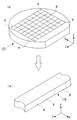
本実施の形態による磁気ヘッドは、図1に示すように、基体の一態様であるスライダ1と、再生用磁気ヘッド素子としてのTMR素子2と、記録用磁気ヘッド素子としての誘導型磁気変換素子3と、保護膜4とを備え、複合型磁気ヘッドとして構成されている。もっとも、本発明による磁気ヘッドは、例えば、TMR素子2に代えてGMR素子やAMR素子などの他の再生用磁気ヘッド素子を備えていてもよいし、再生用磁気ヘッド素子のみ又は記録用磁気ヘッド素子のみを備えていてもよい。また、本実施の形態では、素子2,3はそれぞれ1個ずつ設けられているが、その数は何ら限定されるものではない。
【0076】
スライダ1は磁気記録媒体対向面側にレール部11,12を有し、レール部11、12の表面がABSを構成している。図1に示す例では、レール部11、12の数は2本であるが、これに限らない。例えば、1〜3本のレール部を有してもよいし、ABSはレール部を持たない平面であってもよい。また、浮上特性改善等のために、ABSに種々の幾何学的形状が付されることもある。本発明による磁気ヘッドは、いずれのタイプのスライダを有していてもよい。
【0077】
本実施の形態では、保護膜4はレール部11,12の表面にのみ設けられ、保護膜4の表面がABSを構成している。もっとも、保護膜4は、スライダ1の磁気記録媒体対向面の全面に設けてもよい。保護膜4は、素子2,3の磁気記録媒体に対向する側の面の全体も覆っている。保護膜4については、後に詳述する。
【0078】
TMR素子2及び誘導型磁気変換素子3は、図1に示すように、レール部11、12の空気流出端部TRの側に設けられている。記録媒体移動方向は、図中のX軸方向と一致しており、磁気記録媒体が高速移動した時に動く空気の流出方向と一致する。空気は流入端部LEから入り、流出端部TRから流出する。スライダ1の空気流出端部TRの端面には、TMR素子2に接続されたボンディングパッド5a,5b及び誘導型磁気変換素子3に接続されたボンディングパッド5e,5dが設けられている。
【0079】
TMR素子2及び誘導型磁気変換素子3は、図2及び図3に示すように、スライダ1を構成するセラミック基体15の上に設けられたアンダーコート層16の上に、積層されている。セラミック基体15は、通常、アルチック(Al2O3−TiC)で構成される。Al2O3−TiCは導電性があるので、アンダーコート層16として、例えばAl2O3からなる絶縁膜が用いられている。
【0080】
TMR素子2は、図4に示すように、トンネルバリア層21と、トンネルバリア層21を挟むように積層された第1及び第2の強磁性層22,23とを有している。本実施の形態では、TMR素子2は、強磁性層22の下側に積層された反強磁性層(ピン層)24を有している。これにより、強磁性層22は、反強磁性層24との間の交換結合バイアス磁界によってその磁化方向が所定方向に向くピンド層となっている。一方、強磁性層23は、基本的に磁気情報である外部磁場に応答して自由に磁化の向きが変わるフリー層となっている。また、TMR素子2は、反強磁性層24の下側に積層された下地層25、及び、強磁性層23上に積層されたキャップ層(保護層)26を有している。図3では模式的に示しているが、強磁性層23のZ軸方向の両側には、磁区制御のためのバイアス磁界を付与するバイアス層(磁区制御層)27,28が形成されている。図面では省略されているが、バイアス層27,28の周りに絶縁層が形成されて、バイアス層27,28は他の層と電気的に絶縁されている。
【0081】
強磁性層22,23は、例えば、Fe、Co、Ni、FeCo、NiFe、CoZrNb又はFeCoNiなどの材料で形成される。トンネルバリア層21は、例えば、Al2O3、SiO2、NiO、GdO、MgO、Ta2O5、MoO2、TiO2又はWO2などの材料で形成される。反強磁性層24は、例えば、IrMn合金、FeMn合金、NiMn合金又はPtMn合金等のMn系材料、あるいは、Fe2O3又はNiO等の酸化物系材料で形成される。下地層25は、Ta、Hf又はNb等の材料で形成される。キャップ層26は、Ta又はNb等の材料で形成される。バイアス層27,28は、例えば、Co、TiW/CoPt(コバルト白金合金)、TiW/CoCrPt(コバルトクロム白金合金)などからなる硬磁性材料で形成される。
【0082】
図2乃至図4に示すように、TMR素子2は、NiFeなどの磁性材料からなりTMR素子2の電極を兼ねた下部磁気シールド層34及び上部磁気シールド層35との間において、ギャップ層31,32に挟まれて配置されている。下部磁気シールド層34は、アンダーコート層16上に形成されている。図面には示していないが、TMR素子2は、ギャップ層31,32及び磁気シールド層34,35をそれぞれ介して、前記ボンディングパッド5a,5bにそれぞれ電気的に接続されている。磁気シールド層34,35間には、TMR素子2が形成されていない領域において、ギャップ層31,32から連続して形成されたギャップ層33が介在している。ギャップ層31〜33は、例えば、Al2O3、SiO2、MgO又はTiO2などの材料で形成される。
【0083】
誘導型磁気変換素子3は、図2及び図3に示すように、TMR素子2に対する上部磁気シールド層を兼ねている下部磁性層35、上部磁性層36、コイル層37、アルミナ等からなるライトギャップ層38、ノボラック樹脂等の有機樹脂で構成された絶縁層39及びアルミナ等からなる保護層40などを有している。磁性層36の材質としては、例えば、NiFe又はFeNなどが用いられる。下部磁性層35及び上部磁性層36の先端部は、微小厚みのアルミナなどのライトギャップ層38を隔てて対向する下部ポール部35a及び上部ポール部36aとなっており、下部ポール部35a及び上部ポール部36aにおいて磁気記録媒体に対して情報の書き込みを行なう。下部磁性層35及び上部磁性層36は、そのヨーク部が下部ポール部35a及び上部ポール部36aとは反対側にある結合部41において、磁気回路を完成するように互いに結合されている。絶縁層38の内部には、ヨーク部の結合部41のまわりを渦巻状にまわるように、コイル層37が形成されている。コイル層37の両端は、ボンディングパッド5c,5dに導通されている。コイル層37の巻数及び層数は任意である。また、誘導型磁気変換素子3の構造も任意でよい。
【0084】
前述した保護膜4は、図1乃至図4に示すように、各層16,21〜28,31,32,34〜36,38,40のABS側の端面及びセラミック基体15のABS側の面を覆うように形成されている。この端面には、TMR素子2及び誘導型磁気変換素子3を構成する磁性金属や非磁性金属の金属面が現れており、保護膜4がないと仮定すれば、これらの金属面が露出することになる。
【0085】
本実施の形態では、保護膜4で覆われた面(前記金属面を含む)は水素プラズマ処理などの水素により処理されたものとなっている。本実施の形態では、図4に示すように、保護膜4はDLC膜61のみで構成されている。もっとも、保護膜4は、例えば、図5に示すように、DLC膜61とシリコン膜又は酸化シリコン膜などの下地膜62とから構成してもよい。この場合、下地膜62は、単一の膜のみならず、異なる材料からなる2重以上の膜であってもよい。DLC膜61に代えて他の材料の膜を保護膜4として用いることも可能である。なお、図5は、本実施の形態の変形例を示す拡大断面図であり、図4に対応している。
【0086】
保護膜4の厚さは、保護膜4が図4に示すようにDLC膜61のみで構成される場合及び図5に示すようにDLC膜61と下地膜62で構成される場合のいずれであっても、高記録密度化を図るとともに高耐食性及び長期に渡る高摺動性を得る上で、2nm以上8nm以下であることが好ましい。
【0087】
また、本実施の形態による磁気ヘッドは、前記金属面を構成する金属がCoを含んでいる場合、(a)前記保護膜の厚さが8nm以下であり、(b)当該磁気ヘッドを0.1%の硫酸水溶液に30分時間浸漬した後にESCAで測定したときの炭素aの析出量に対するCoの析出量bの比(100×b/a)が、10%以下であり、(c)当該磁気ヘッドを搭載した磁気ディスク装置又はその試験器において、当該磁気ヘッドの荷重が2.5gとされて、磁気記録媒体が停止状態から3秒間で7200rpmまで立ち上がった後に7200rpmでの回転状態を3秒間継続した後に3秒間で立ち下がって停止して停止状態を3秒間継続するCSS(コンタクト・スタート・ストップ)動作を、1回のCSS動作として、当該CSS動作を1万回連続的に繰り返した後の前記保護膜の摩擦係数が2.5以下であることが、好ましい。この摩擦係数は、2.3以下であることがより好ましく、2.0以下であることがより一層好ましい。
【0088】
本実施の形態による磁気ヘッドでは、前記金属面が水素処理されたものであるので、保護膜4を薄くしても、前記金属面に対して高耐腐食性を得ることができる。保護膜4としてDLC膜61が用いられているので、長期に渡る高摺動性(低摩擦性)を得ることができる。また、前記金属面が水素処理されたものであるので、下地膜62を介することなくDLC膜61を直接成膜することが可能となっている。
【0089】
なお、保護膜4上に潤滑剤を塗布しておいてもよいが、潤滑剤を塗布しなくても所望の高摺動性を得ることができる。
【0090】
次に、本実施の形態による磁気ヘッドの製造方法の一例について、図6及び図7を参照して説明する。図6は、この製造方法を示すフローチャートである。図7は、ウエハ工程後のバー116の切り出し工程を模式的に示す概略斜視図である。
【0091】
まず、ウエハ工程(ステップS1)を行う。すなわち、セラミック基体15となるべきAl2O3−TiC等のウエハ115を用意し、薄膜形成技術等を用いて、ウエハ115上の多数の磁気ヘッド素子のマトリクス状の形成領域にそれぞれ、前述した各層16,21〜28,31〜40及びボンディングパッド5a〜5dなど、保護膜4以外の要素を形成する。図7(a)は、このウエハ工程を経たウエハ115を示している。ただし、図7(a)では、ウエハ115に形成された要素は省略し、個々の磁気ヘッド素子の領域Rのみを示している。
【0092】
次に、図7(a)に示すウエハ115を切断して、基体上に複数の磁気ヘッドの部分が一列状に配列された各バー(バー状磁気ヘッド集合体)116をダイヤモンドカッター等で切り出す(ステップS2)。図7(b)はこのバー116を示している。このバー116の図7(b)のXZ平面に平行な上面はABS側の面であり、この面には図2中の各層16,21〜28,31,32,34〜36,38,40の端面などが現れ、また、図7(b)中のYZ平面に平行で手前に見えている面には図1中のボンディングパッド5a〜5d等が現れるが、それらの図示は省略している。
【0093】
次いで、図7(b)に示すバー116に対して、スロートハイト、MRハイト等を設定するために、そのABS側にラッピング処理(研磨)を施す(ステップS3)。この処理では、例えば、バー116を固定治具にセットして、定盤に押し当てダイヤモンド砥粒を含む懸濁液を滴下し、定盤を回転してABS側の面を研磨する。
【0094】
このラッピング処理後、図3中の磁性層31,32間等で、電気的な導通が生ずるスメア現象が生ずる場合がある。このような現象が生じているか否か抵抗計等で確認し、スメアが生じている場合には、このスメアを除去するため、ラッピング処理後のバー116のABS側の面をドライエッチングする(ステップS4)。このドライエッチングは、例えば、ミリング又は逆スパッタにより行うことができる。このドライエッチングは、スメアの原因となっている金属成分を除去することが目的である。したがって、ミリングを行う場合、水素では質量がなさ過ぎることから、スパッタと同じArガス又はArより質量のある単原子分子を用いることが、好ましい。ミリングを行う場合、例えば、チャンバーを10−5〜10−10Torrまで排気した後、ガスをミリングガンに導入して放電を発生させ、電圧が印加されたグリッドによりイオン化ガスを引き出し、イオン化ガスをバー116に照射する。このとき、加速電圧として、例えば100V〜500Vを印加する。ステップS4では、ドライエッチングに代えて、薬液によるウエットエッチング等を行うことにより、スメアを除去してもよい。
【0095】
ラッピング処理後に、スメア現象が生じていないことが確認されれば、ステップS4を行わなくてもよい。あるいは、スメア現象の発生の有無を確認することなく、常に、ラッピング処理後のバー116に対してステップS4を行うようにしてもよい。
【0096】
次に、バー116を洗浄する(ステップS5)。この洗浄として、例えば、アルコールなどで油分を拭き取ってもよいし、超音波洗浄等を行ってもよい。もっとも、これらの洗浄処理は、必ずしも必要ではない。
【0097】
その後、バー116のABS側の面に対して、水素により処理を行う(ステップS6)。この水素処理としては、例えば、比較的高温で水素雰囲気に晒す処理を行ってもよいが、水素プラズマ処理を行うことが好ましい。
【0098】
水素プラズマ処理は、単純な平行平板型、誘導型、容量型あるいはマイクロ波ECRなどのいずれのプラズマ処理装置を用いて行ってもよい。使用するプラズマ処理装置は、特に限定されるものではない。また、水素プラズマ処理に使用し得る装置はプラズマ処理装置に限らず、例えば、ミリング装置やエッチング装置などのイオン加速装置を用いて水素プラズマ処理を行ってもよい。プラズマ処理装置を用いて水素プラズマ処理を行う場合、バー116を当該処理装置にセットし、放電を発生させて処理を行う。
【0099】
水素プラズマ処理では、例えば、まず、チャンバーを10−5〜10−10Torrまで排気した後、水素ガスを所望の圧力までマスフローコントローラにて導入する。所定の圧力になったら、放電を発生させる。放電電源は、特に制限はないが、磁気ヘッド素子へのダメージを低減させるためには、高周波電源を用いることが望ましい。1kHz〜40MHz程度の周波数が好ましく、100kHz〜14MHz程度の周波数が特に好ましい。現状では、この範囲の周波数の電源が入手し易いし、放電も安定している。バー116は、処理の均一性を高めるために、処理中に回転させた方が望ましい。放電時間は、水素処理により金属面に還元状態を作るためには、ある程度の時間が必要だが、必要な時間は適宜実験で確認しておけばよい。
【0100】
前記水素処理の後、バー116のABS側の面の全体に、保護膜4を形成する(ステップS7)。この保護膜形成工程は、前記水素処理の後にバー116を大気に晒すことなく、前記水素処理と連続して行うことが好ましい。水素処理の後にバー116を大気に晒すと、水素プラズマ処理の効果が低減してしまうとともに、コンタミ等が付着するおそれがあるためである。
【0101】
この保護膜形成工程では、図4に示すように保護膜4をDLC膜61のみで構成する場合には、前記水素処理の後にDLC膜を成膜する。一方、図5に示すように保護膜4をDLC膜61と下地膜62で構成する場合には、下地膜を成膜した後に、DLC膜を成膜する。
【0102】
いずれの場合であっても、DLC膜は、例えば、プラズマCVD法又はアーク放電法により成膜することができる。
【0103】
プラズマCVD法を採用する場合は、基板処理を考慮すると、平行平板型のプラズマCVD装置かあるいはマイクロ波グロー放電のプラズマCVD装置が使い易い。また、多くの場合、ECR(electron cyclotron resonance)型で実施されるが、特に手法は限定されるものではない。いかなる手法でも、その膜質が問題になる。膜厚30nm〜60nm程度をシリコンウエハに成膜したときの当該膜の屈折率が2〜2.35となるような条件で、DLC膜を成膜することが望ましく、特に、当該膜の屈折率が2.2〜2.3となるような条件でDLC膜を成膜することが望ましい。炭素及び水素からなる物質では、屈折率と硬度との間に相関関係があり、屈折率が高いほど硬度が高くなり、屈折率を硬度の指標とすることができることが知られている。また、硬度が高いと摩擦係数が低くなる。屈折率が2を越えると摩擦係数が比較的十分に低下する。一方、屈折率を2.35を越える値にするにはより大きなパワーが必要となるにも関わらず、屈折率が2.35を越えても、屈折率が2.35の場合に比べてさほど摩擦係数が低くならない。製造バラツキ等を考慮すると、前記屈折率が2.2程度となるような条件でDLC膜を成膜することが望ましい。できるだけ緻密な膜構造となるよう手法で、DLC膜を成膜することが好ましい。
【0104】
プラズマCVD法で使用されるガスは、メタン、エタン、プロパン、ブタン、エチレン、アセチレン、プロピレンなどの、炭化水素系のガスであれば、特に制限はない。原料がベンゼン、トルエンなどの液体炭化水素でも当然問題ない。液体炭化水素を原料として用いる場合、ベーキングシステム等を使用すれば、簡単に液体原料をガス化して反応系に導入できる。プラズマCVD法で使用する周波数は、平行平板型のプラズマCVD装置を用いる場合、1kHz〜1MHz程度が望ましい。あまり高周波にすると、バイアスをかけるなどの改善が必要となるが、例えば40MHzくらいまでは問題なく使用できる。マイクロ波放電を用いる場合、ECR条件であってもなくても問題ない。この場合、ガス圧等を制御すれば、硬い膜を成膜することができる。
【0105】
他方、アーク放電法によりDLC膜を成膜する場合は、Arガスをノズルから噴出し、グラファイトターゲットに向けてアーク状態を発生させ、そのエネルギーで炭素原子をイオン化して蒸発させ、バー116に導いてDLC膜を成膜させる。この手法では、高エネルギーの炭素イオンを形成することができるので、成膜された膜はかなり硬くなり、また水素を含まない系なので反応種が均一であり薄くすることの特徴を出せる。このアーク放電法で成膜された膜は、熱伝導性も良く、硬質グラッシー膜となる。
【0106】
アーク放電法の手法の一つであるが、前記手法と異なる次の手法でDLC膜を成膜してもよい。すなわち、グラファイトロッドにストライカーにてアークを発生させて直接炭素を揮発させ、イオン化している炭素原子又はクラスターを磁場にて偏向させ、バー116に指向させる手法を採用してもよい。この手法によっても、硬度的には硬く、保護膜として適した膜を形成することができる。
【0107】
下地膜62を作製する場合において、下地膜62をシリコン膜又は酸化シリコン膜で構成する場合には、下地膜は、例えば、シリコンのスパッタかあるいは酸化シリコンのスパッタ又はCVDにより、成膜される。
【0108】
本実施の形態では、以上説明した保護膜形成工程(ステップS7)の前に、前述したステップS6の工程で、バー116のABS側の面に、水素プラズマ処理等の水素処理が施されている。このため、保護膜形成工程においてバー116のABS側の面に保護膜4を形成すると、当該面に下地膜62を介してDLC膜61を形成するときには当該面(この面に現れた金属面を含む)と下地膜62との接着が、当該面に直接DLC膜61を成膜するときは、当該面とDLC膜61との接着が、改善される。これにより、非常に薄くても保護効果の高い保護膜4の構造を得ることができる。
【0109】
ステップS7の後に、バー116のABS側の面のレール11,12領域以外の領域を選択的にエッチングして、レール11,12を形成する(ステップS8)。最後に、機械加工により切断してバー116を個々の磁気ヘッドに分離する(ステップS9)。これにより、本実施の形態による磁気ヘッドが完成する。
【0110】
[第2の実施の形態]
【0111】
図8は、本発明の第2の実施の形態による磁気ヘッドの要部を模式的に示す拡大断面図であり、前述した図4に対応している。図8において、図4中の要素と同一又は対応する要素には同一符号を付している。
【0112】
本実施の形態による磁気ヘッドが前記第1の実施の形態と異なる所は、以下に説明する点のみであるので、重複する説明は省略する。
【0113】
前記第1の態様による磁気ヘッドでは、保護膜4で覆われた面(この面には、TMR素子2及び誘導型磁気変換素子3を構成する磁性金属や非磁性金属の金属面が現れている。)は、水素プラズマ処理などの水素処理が施されたものとなっていた。これに対し、本実施の形態では、保護膜4で覆われた面(前記金属面を含む)は、水素により処理されたものではなく、ハロゲンを含む化合物又はハロゲン分子のプラズマ処理などの、不動態化処理が施されたものとなっており、前記金属面には不動態皮膜等の不動態部が形成されている。なお、図8では、図面表記の便宜上、強磁性膜22,23の面にそれぞれ形成された不動態部22a,23aのみを示しているが、他の金属面にも同様に不動態部が形成される。不動態部22aは強磁性膜22を構成する金属のハロゲン化物を含み、不動態部23aは強磁性膜23を構成する金属のハロゲン化物を含んでいる。例えば、強磁性膜22がFeで構成されている場合には、不動態部22aはFeのハロゲン化物(例えば、塩化鉄など)となる。もっとも、本発明では、金属面上の前記不動態部は、必ずしも、当該金属面を構成する金属のハロゲン化物を含んでいなくてもよい。
【0114】
前記不動態部の厚さは、例えば、1原子層乃至数原子層(例えば、1原子層乃至5原子層)程度が好ましい。例えば、不動態部22a,23aの厚さが1原子層程度であっても高耐腐食性を得ることができ、不動態部22a,23aの厚さが厚過ぎると、強磁性膜22,23が構成する磁気特性に影響を与えてしまう。
【0115】
本実施の形態では、図4に示すように、保護膜4はDLC膜61のみで構成されている。もっとも、保護膜4は、例えば、図9に示すように、DLC膜61とシリコン膜又は酸化シリコン膜などの下地膜62とから構成してもよい。この場合、下地膜62は、単一の膜のみならず、異なる材料からなる2重以上の膜であってもよい。DLC膜61に代えて他の材料の膜を保護膜4として用いることも可能である。なお、図9は、本実施の形態の変形例を示す拡大断面図であり、図8に対応している。
【0116】
保護膜4の厚さは、保護膜4が図8に示すようにDLC膜61のみで構成される場合、及び、図9に示すようにDLC膜61と下地膜62で構成される場合のいずれであっても、高記録密度化を図るとともに高耐食性及び長期に渡る高摺動性を得る上で、2nm以上8nm以下であることが好ましい。
【0117】
また、本実施の形態による磁気ヘッドは、前記金属面を構成する金属がCoを含んでいる場合、(a)前記保護膜の厚さが8nm以下であり、(b)当該磁気ヘッドを0.1%の硫酸水溶液に30分時間浸漬した後にESCAで測定したときの炭素の析出量aに対するCoの析出量bの比(100×b/a)が、10%以下であり、(c)当該磁気ヘッドを搭載した磁気ディスク装置又はその試験器において、当該磁気ヘッドの荷重が2.5gとされて、磁気記録媒体が停止状態から3秒間で7200rpmまで立ち上がった後に7200rpmでの回転状態を3秒間継続した後に3秒間で立ち下がって停止して停止状態を3秒間継続するCSS(コンタクト・スタート・ストップ)動作を、1回のCSS動作として、当該CSS動作を1万回連続的に繰り返した後の前記保護膜の摩擦係数が2.5以下であることが、好ましい。この摩擦係数は、2.3以下であることがより好ましく、2.0以下であることがより一層好ましい。
【0118】
本実施の形態による磁気ヘッドでは、前記金属面に不動態部22a,23a等が形成されているので、保護膜4を薄くしても、前記金属面に対して高耐腐食性を得ることができる。保護膜4としてDLC膜61が用いられているので、長期に渡る高摺動性(低摩擦性)を得ることができる。また、前記金属面に不動態部22a,23a等が形成されているので、下地膜62を介することなくDLC膜61を直接成膜することが可能となっている。
【0119】
なお、保護膜4上に潤滑剤を塗布しておいてもよいが、潤滑剤を塗布しなくても所望の高摺動性を得ることができる。
【0120】
次に、本実施の形態による磁気ヘッドの製造方法の一例について、図10を参照して説明する。図10は、この製造方法を示すフローチャートである。図10において、図6中のステップと同一又は対応するステップには同一符号を付し、その重複する説明は省略する。
【0121】
図10に示すように、本実施の形態による磁気ヘッドの製造方法においても、前述したステップS1〜S5を経る点、及び、ステップS4,S5は必ずしも行わなくてもよい点は、前記第1の実施の形態による磁気ヘッドの前述した製造方法と同じである。
【0122】
本実施の形態による磁気ヘッドの製造方法が前記第1の実施の形態による磁気ヘッドの前述した製造方法と異なる所は、図6中の水素処理(ステップS6)に代えて、不動態化処理(ステップS10)を行う点である。
【0123】
ステップS10では、基体上に磁気ヘッド素子が形成されているバー116(図7参照)のABS側の面に対して、不動態化処理を行う。この不動態化処理としては、例えば、ハロゲンを含む化合物やハロゲン分子の雰囲気に高温で晒す処理を行ってもよいが、ハロゲンを含む化合物又はハロゲン分子のプラズマ処理(以下、単に「ハロゲンプラズマ処理」という。)を行うことが好ましい。
【0124】
ハロゲンプラズマ処理は、単純な平行平板型、誘導型、容量型あるいはマイクロ波ECRなどのいずれのプラズマ処理装置を用いて行ってもよい。使用するプラズマ処理装置は、特に限定されるものではない。また、ハロゲンプラズマ処理に使用し得る装置はプラズマ処理装置に限らず、例えば、ミリング装置やエッチング装置などのイオン加速装置を用いてハロゲンプラズマ処理を行ってもよい。プラズマ処理装置を用いてハロゲンプラズマ処理を行う場合、バー116を当該処理装置にセットし、放電を発生させて処理を行う。
【0125】
ハロゲンプラズマ処理に用いるハロゲン分子としては、塩素、臭素、ヨウ素が好ましく、フッ素は撥水性が強いため好ましくない。ヨウ素より原子番号の大きいものは、通常は固体化しているため、使用しにくい。ハロゲンプラズマ処理に用いるハロゲン化合物としては、クロロホルム、四塩化炭素などと、それらの臭化物及びヨウ化物などを挙げることができる。
【0126】
ハロゲンプラズマ処理では、例えば、まず、チャンバーを10−5〜10−10Torrまで排気した後、前述したガスを所望の圧力までマスフローコントローラにて導入する。所定の圧力になったら、放電を発生させる。放電電源は、特に制限はないが、磁気ヘッド素子へのダメージを低減させるためには、高周波電源を用いることが望ましい。1kHz〜40MHz程度の周波数が好ましく、100kHz〜14MHz程度の周波数が特に好ましい。現状では、この範囲の周波数の電源が入手し易いし、放電も安定している。バー116は、処理の均一性を高めるために、処理中に回転させた方が望ましい。放電時間は、ハロゲンプラズマ処理により金属面にパッシベーション状態を作るためには、ある程度の時間が必要だが、必要な時間は適宜実験で確認しておけばよい。
【0127】
前記不動態化処理処理の後、バー116のABS側の面の全体に、保護膜4を形成する(ステップS11)。この保護膜形成工程は、前記不動態化処理の後にバー116を大気に晒すことなく、前記不動態化処理と連続して行うことが好ましい。不動態化処理の後にバー116を大気に晒すと、コンタミ等が付着するおそれがあるためである。
【0128】
ステップS11の保護膜形成工程では、図8に示すように保護膜4をDLC膜61のみで構成する場合には、前記不動態化処理の後にDLC膜を成膜する。一方、図9に示すように保護膜4をDLC膜61と下地膜62で構成する場合には、下地膜を成膜した後に、DLC膜を成膜する。ステップS11の保護膜形成工程では、前述した図6中の保護膜形成工程と同じ方法で保護膜4を形成することができる。
【0129】
本実施の形態では、ステップS11の保護膜形成工程の前に、前述したステップS10の工程でバー116のABS側の面にハロゲンプラズマ処理などの不動態化処理が施されている。このため、保護膜形成工程においてバー116のABS側の面に保護膜4を形成すると、当該面に下地膜62を介してDLC膜61を形成するときには当該面(この面に現れた金属面を含む)と下地膜62との接着が、当該面に直接DLC膜61を成膜するときは当該面とDLC膜61との接着が、改善される。この場合、不動態化処理により形成された不動態部22a,23a等によって耐腐食性のかなりの部分をカバーし、摺動性はDLC膜61によって確保するイメージとなる。
【0130】
ステップS11の後に、バー116のABS側の面のレール11,12領域以外の領域を選択的にエッチングして、レール11,12を形成する(ステップS12)。最後に、機械加工により切断してバー116を個々の磁気ヘッドに分離する(ステップS13)。これにより、本実施の形態による磁気ヘッドが完成する。
【0131】
[第3の実施の形態]
【0132】
図11は、本発明の第3の実施の形態によるヘッドサスペンションアセンブリを示す磁気記録媒体対向面側から見た概略平面図である。
【0133】
本実施の形態によるヘッドサスペンションアセンブリは、磁気ヘッド71と、磁気ヘッド1が先端部付近に搭載され磁気ヘッド71を支持するサスペンション72と、を備えている。磁気ヘッド71として、前述した第1及び第2の実施の形態並びにそれらの変形例に係るいずれかの磁気ヘッドが、用いられている。
【0134】
サスペンション72は、磁気ヘッド71が装着されるフレクシャ73と、フレクシャ73を支持し磁気ヘッド71のスライダ1(図11では図示せず)に押圧力(荷重)を付与するロードビーム74と、ベースプレート75と、を有している。
【0135】
フレクシャ73は、図面には示していないが、先端側から基端側にかけて、帯状に延びた薄いステンレス鋼板等からなる基板と、該基板上に形成されたポリイミド層等からなる絶縁層と、該絶縁層上に形成された信号入出力用の4本の導体パターン81a〜81dと、これらの上に形成されたポリイミド層等からなる保護層と、から構成されている。導体パターン81a〜81dは、フレクシャ73の長さ方向にほぼその全長に渡って形成されている。
【0136】
フレクシャ73の先端部には、平面視で略々コ字状の抜き溝82が形成されることによりジンバル部83が構成され、ジンバル部83に磁気ヘッド1が接着剤等により接合されている。フレクシャ73には、磁気ヘッド1のボンディングパッド5a〜5d(図1参照)と近接する箇所において、導体パターン81a〜81dの一端部がそれぞれ電気的に接続された4つのボンディングパッドが、それぞれ形成されている。これらのボンディングパッドは、金ボール等により磁気ヘッド1のボンディングパッド5a〜5dにそれぞれ電気的に接続されている。また、フレクシャ73の基端側には、導体パターン81a〜81dの他端部がそれぞれ電気的に接続された外部回路接続用のボンディングパッド84a〜84dが、形成されている。
【0137】
ロードビーム74は、比較的厚いステンレス鋼板等によって形成されている。ロードビーム74は、先端側の平面視で略三角形状の剛性部74aと、基端側のベースプレート接合部と、剛性部74aと前記接合部との間に位置し磁気ヘッド1のスライダ1に付与する押圧力を発生させる弾性部74bと、前記接合部から側方に延在しフレクシャ74の基端側部分を支持する支持部74cと、を有している。図11において、74dは剛性部74aの剛性を高めるための折り曲げ起立部、74eは弾性部74bが発生する押圧力を調整する穴である。ロードビーム74の剛性部74aには、フレクシャ73が、レーザ溶接等による複数のスポット溶接点91で固着されている。また、ロードビーム74の前記接合部には、ベースプレート75が、複数のスポット溶接点92で固着されている。フレクシャ73の基端側部分は、ベースプレート75から側方にはみ出したロードビーム74の支持部74cにより、支持されている。
【0138】
本実施の形態では、磁気ヘッド71として、前述した第1及び第2の実施の形態並びにそれらの変形例に係るいずれかの磁気ヘッドが、搭載されているので、本実施の形態によるヘッドサスペンションアセンブリを磁気ディスク装置等に用いれば、当該磁気ディスク装置等の高記録密度化及び長寿命化を図ることができる。
【0139】
【実施例】
ラッピング処理が完了した前述したバー116に相当し互いに同じ構造を持つ多数のバー(以下、「サンプルバー」という。)を、図6中のステップS1〜S3の工程に相当する方法で、作製した。これらのサンプルバーの膜構造等は、図2乃至図4に示す膜構造から説明する。主な膜構造は、基体15となるべきウエハをAlTiC基板、アンダーコート層16を厚さ5μmのアルミナ層、下部磁気シールド層34を厚さ2μmのパーマロイ、ギャップ層31を厚さ0.05μmのTa層、TMR素子2の層の全体の厚さを350Å、バイアス層27,28を厚さ350ÅのCo層、ギャップ層32を厚さ0.05μmのTa層、上部磁気シールド層(下部磁性層)35を厚さ4μmのパーマロイ、ライトギャップ層38を厚さ0.3μmのパーマロイとした。上部磁性層36は、上部磁性層36の先端部である上部ポール部36aの高さが5μm、上部ポール部36aの幅が0.5μmとなるように、パーマロイで形成した。保護層40は、アルミナを用いて、全厚が30μmとなるように成膜した。TMR素子2の層構造は次の通りとした。すなわち、下地層25は、ギャップ層31側から順に積層した、厚さ3nmのTa層、厚さ3nmのパーマロイ層、厚さ20nmの銅層、及び、厚さ3nmのパーマロイ層とした。反強磁性層24を厚さ10nmのIr−Mn層、強磁性層(ピンド層)22を厚さ4nmのCo−Fe層、トンネルバリア層21をAl酸化膜とした。強磁性層(フリー層)23は、トンネルバリア層21側から順に積層した厚さ4nmのCo−Fe層及び厚さ20nmのNi−Fe層とした。キャップ層26は、厚さ5nmのTa層とした。
【0140】
これらのサンプルバーに対して下記の表1に示す処理を施したものを、実施例1〜14及び比較例1〜4のサンプルとした。ただし、実施例1〜5,8〜12及び比較例1〜4のサンプルは、スメアが発生していなかったサンプルバーを用いた。実施例6,7,13,14のサンプルは、スメアが発生していたサンプルバーを用いた。表1において、サンプルバーに対して施した処理についてのみ○印を付している。なお、表1には示していないが、実施例1〜14及び比較例1〜4では、図6中のステップS5に相当する洗浄処理として、溶剤による超音波洗浄処理を、後述する水素プラズマ処理又はハロゲンプラズマ処理の前に(スメア除去処理を行う場合には、スメア除去後に)、サンプルバーに対して行った。
【0141】
【表1】

実施例1〜7は前記第1の実施の形態又はその変形例に対応しており、実施例8〜14は前記第2の実施の形態又はその変形例に対応している。
【0143】
実施例6,7,13,14では、最初に、図6中のステップS4に相当するスメア除去処理として、同一条件でミリングを行った。実施例1〜5,8〜12及び比較例1〜4では、このスメア除去処理は行わなかった。
【0144】
実施例1〜7では、サンプルバーに対して、最初に又はスメア除去処理後に、水素プラズマ処理を施した。この水素プラズマ処理は次のようにして行った。すなわち、チャンバー内の平行平板の電極間にサンプルバーをセットし、10−7Torrまで排気した後、水素を20sccmの流量で導入しながら、5×10⁻³Torrに圧力調整し、100kHzの周波数で放電を発生させた。この状態で、サンプルバーを回転させながら10分間処理を行った。
【0145】
実施例8〜14では、サンプルバーに対して、最初に又はスメア除去処理後に、ハロゲンプラズマ処理を施した。このハロゲンプラズマ処理は次のようにして行った。すなわち、チャンバー内の平行平板の電極間にサンプルバーをセットし、10−7Torrまで排気した後、塩素を20sccmの流量で導入しながら、5×10⁻³Torrに圧力調整し、100kHzの周波数で放電を発生させた。この状態で、サンプルバーを回転させながら10分間処理を行った。
【0146】
比較例1〜4では、サンプルバーに対して、水素プラズマ処理もハロゲンプラズマ処理も施さなかった。
【0147】
実施例4,7では、前記水素プラズマ処理と連続して、前記水素プラズマ処理の後のサンプルバーを真空条件下でスパッタ室に移動し、サンプルバーのABS側の面に、シリコン下地膜をスパッタにより成膜した。実施例11,14では、前記ハロゲンプラズマ処理と連続して、前記ハロゲンプラズマ処理の後のサンプルバーを真空条件下でスパッタ室に移動し、サンプルバーのABS側の面に、シリコン下地膜をスパッタにより成膜した。比較例2,3では、最初に、スパッタ室で、サンプルバーのABS側の面に、シリコン下地膜をスパッタにより成膜した。いずれの場合も、シリコン下地膜の成膜条件は同一とした。ただし、シリコン下地膜の厚さは、実施例4,7,11,14及び比較例2では2nm、比較例3では5nmとした。シリコン下地膜の膜厚は、予め実験により成膜のレートを確認した上で、時間管理により設定した。
【0148】
実施例5では、前記水素プラズマ処理と連続して、前記水素プラズマ処理と同一のチャンバー内で、原料ガスとしてTEOS(テトラエトキシシラン)を導入しながら酸素を等量導入して、100kHzの周波数で放電を発生させ、サンプルバーのABS側の面にSiOx下地膜(酸化シリコン膜)を成膜した。実施例12では、前記ハロゲンプラズマ処理と連続して、前記ハロゲンプラズマ処理と同一のチャンバー内で、原料ガスとしてTEOSを導入しながら酸素を等量導入して、100kHzの周波数で放電を発生させ、サンプルバーのABS側の面にSiOx下地膜(酸化シリコン膜)を成膜した。比較例4では、最初に、チャンバー内で、原料ガスとしてTEOSを導入しながら酸素を等量導入して、100kHzの周波数で放電を発生させ、サンプルバーのABS側の面にSiOx下地膜(酸化シリコン膜)を成膜した。いずれの場合も、SiOx下地膜の成膜条件は同一とした。ただし、SiOx下地膜の厚さは、実施例5,12では2nm、比較例4では5nmとした。SiOx下地膜の膜厚は、予め実験により成膜のレートを確認した上で、時間管理により設定した。
【0149】
実施例1〜3,6,8〜10,13及び比較例1では、シリコン下地膜及びSiOx下地膜のいずれも成膜しなかった。
【0150】
実施例1では、前記水素プラズマ処理と連続して、前記水素プラズマ処理と同一のチャンバー内で、メタンを導入して、100kHzの周波数で放電を発生させ、平行平板型の装置によるプラズマCVD法により、サンプルバーのABS側の面にDLC膜を成膜した。実施例8では、前記ハロゲンプラズマ処理と連続して、前記ハロゲンプラズマ処理と同一のチャンバー内で、メタンを導入して、100kHzの周波数で放電を発生させ、平行平板型の装置によるプラズマCVD法により、サンプルバーのABS側の面にDLC膜を成膜した。実施例1,8のいずれの場合も、DLC膜の成膜条件は同一とし、サンプルバーを回転させながら厚さ2nmのDLC膜を成膜した。この成膜条件は、予め実験によりDLC膜を50nm成膜してそのDLC膜の屈折率が2.2以上であること及び成膜のレートを確認した条件とした。DLC膜の膜厚は、確認されたレートに基づいて、時間管理により設定した。
【0151】
実施例2,6では水素プラズマ処理後に、実施例4,7,11,14及び比較例2,3ではシリコン下地膜の成膜後に、実施例5,12及び比較例4ではSiOx下地膜の成膜後に、実施例9,13ではハロゲンプラズマ処理後に、比較例1では最初に、ECR装置にサンプルバーを搬送して、同一条件でECRプラズマCVD法によりサンプルバーのABS側の面にDLC膜を成膜した。この成膜条件は、予め実験によりDLC膜を50nm成膜してそのDLC膜の屈折率が2.2以上であること及び成膜のレートを確認した条件とした。DLC膜の膜厚は、確認されたレートに基づいて、時間管理により設定した。DLC膜の膜厚は、実施例2,4〜7,9,11〜14及び比較例1,2では2nm、比較例3,4では5nmとした。
【0152】
実施例3では水素プラズマ処理後に、実施例10ではハロゲンプラズマ処理後に、アーク放電装置にサンプルバーを搬送して、同一条件でアーク放電法によりサンプルバーのABS側の面に厚さ2nmのDLC膜を成膜した。この成膜条件は、予め実験によりDLC膜を50nm成膜してそのDLC膜の屈折率が2.2以上であること及び成膜のレートを確認した条件とした。DLC膜の膜厚は、確認されたレートに基づいて、時間管理により設定した。
【0153】
実施例1〜14及び比較例1〜4のサンプルについて、摩擦摺動性の測定及び腐食テストを行った。その結果を下記の表2に示す。
【0154】
【表2】
摩擦摺動性の測定は、次のようにして行った。各サンプルに対して図6中のステップS8,S9の処理を行って、各サンプルから磁気ヘッドをそれぞれ作製した。そして、これらの各磁気ヘッドを交洋製作所製のCSSテスターに取り付け、磁気ディスクに2.5gの圧力で押し付け、磁気ディスクが磁気ディスクから浮上せずに接触したままとなる回転数1rpmで回転させ、サスペンションにかかる力を測定し、その力を摩擦係数に換算した。この摩擦係数の測定は、各磁気ヘッドについて、初期状態、及び、連続的に繰り返した1万回のCSS動作後の状態において、行った。
【0156】
ここで、1回のCSS動作は、次の通りとした。すなわち、当該磁気ヘッドを搭載したCSSテスターにおいて、当該磁気ヘッドの荷重が2.5gとされて、磁気記録媒体が停止状態から3秒間で7200rpmまで立ち上がった後に7200rpmでの回転状態を3秒間継続した後に3秒間で立ち下がって停止して停止状態を3秒間継続するCSS動作を、1回のCSS動作とした。
【0157】
また、腐食テストは、バー状態の各サンプルを0.1%の硫酸水溶液に30分間浸漬した後、Coの析出量とC(炭素)の析出量を、ESCAで測定し、Cの析出量aに対するCoの析出量bの比(100×b/a)を算出した。表2において、Coの析出量が確認できない場合(前記比が0%の場合)を○とし、Coの析出量が確認できたが前記比が10%未満の場合を△とし、前記比が10%以上の場合を×とした。
【0158】
表2に示すように、水素プラズマ処理又はハロゲンプラズマ処理を行った実施例1〜14では、保護膜の厚さが2nm(保護膜がDLC膜のみで構成されている場合)又は4nm(保護膜がDLC膜及び下地膜で構成されている場合)と非常に薄いにも関わらず、1万回CSS動作後の摩擦係数が低いとともに、腐食テストの結果も良好であった。このことから、水素プラズマ処理又はハロゲンプラズマ処理を行うことにより、保護膜における下地膜の有無やスメア除去処理の有無やDLC膜の製法の差異に関わらず、保護膜が薄くても、高耐腐食性及び長期に渡る高摺動性(低摩擦性)の両方を同時に得ることができることがわかる。
【0159】
これに対し、水素プラズマ処理又はハロゲンプラズマ処理も行わなかった比較例1〜4についてみると、比較例3のように保護膜の厚さを10nmと厚くしない限り、高耐腐食性及び長期に渡る高摺動性(低摩擦性)の両方を同時に得ることができないことがわかる。
【0160】
なお、実施例1,8では、腐食テストにおいてCoの析出量が確認されたが、DLC膜の成膜に用いた装置が内部電極型の装置であったので、幾分コンタミの影響が出た可能性がある。しかし、実施例1,8の場合も、腐食テストは良好であったと言える。
【0161】
以上、本発明の各実施の形態及びその変形例並びに実施例について説明したが、本発明はこれらの例に限定されるものではない。
【0162】
例えば、前述した各実施の形態等で説明した磁気ヘッドの製造方法は、本発明による保護膜形成方法を磁気ヘッドの製造方法に適用した例であったが、本発明による保護膜形成方法は他の種々の用途の保護膜形成方法にも適用することができる。
【0163】
【発明の効果】
以上説明したように、本発明によれば、少なくとも1つの金属の面を含む所定の面上に形成される保護膜を薄くしても、高い耐腐食性を得ることができる、保護膜形成方法を提供することができる。
【0164】
また、本発明によれば、磁気記録媒体に対向する側の基体の面の少なくとも一部及び磁気記録媒体に対向する側の磁気ヘッド素子の面における少なくとも金属面に形成された保護膜を薄くしても、高耐腐食性及び長期に渡る高摺動性(低摩擦性)を得ることができる、磁気ヘッド及びその製造方法を提供することができる。
【0165】
さらに、本発明によれば、磁気ディスク装置等の高記録密度化及び長寿命化を図ることができるヘッドサスペンションアセンブリを提供することができる。
【図面の簡単な説明】
【図1】本発明の第1の実施の形態による磁気ヘッドを模式的に示す概略斜視図である。
【図2】図1に示す磁気ヘッドのTMR素子及び誘導型磁気変換素子の部分を模式的に示す拡大断面図である。
【図3】図2中のA−A’矢視概略図である。
【図4】図2中のB部付近を更に拡大した拡大図である。
【図5】第1の実施の形態の変形例を示す拡大断面図である。
【図6】第1の実施の形態による磁気ヘッドの製造方法の一例を示すフローチャートである。
【図7】ウエハ工程後のバーの切り出し工程を模式的に示す概略斜視図である。
【図8】本発明の第2の実施の形態による磁気ヘッドの要部を模式的に示す拡大断面図である。
【図9】第2の実施の形態の変形例を示す拡大断面図である。
【図10】第2の実施の形態による磁気ヘッドの製造方法の一例を示すフローチャートである。
【図11】本発明の第3の実施の形態によるヘッドサスペンションアセンブリを示す概略平面図である。
【符号の説明】
1 スライダ
2 TMR素子
3 誘導型磁気変換素子
4 保護膜
61 DLC膜
62 下地膜
22a,23a 不動態部[0001]
BACKGROUND OF THE INVENTION
The present invention provides a protective film forming method for forming a protective film on a predetermined surface including at least one metal surface, a magnetic head on which a protective film is formed, a method for manufacturing the same, and such a magnetic head. The present invention relates to a head suspension assembly.
[0002]
[Prior art]
Conventionally, in order to improve the corrosion resistance of a metal surface, a protective film is formed on a predetermined surface including at least one metal surface. Among applications that require the formation of such a protective film, there are applications that require a very thin protective film. Examples of such applications include magnetic heads used in magnetic disk devices such as hard disk devices.
[0003]
In magnetic disk devices, higher recording density is being promoted in order to reduce the size and increase the capacity. For this reason, a base and a magnetic head formed on the base by thin film technology or the like are provided. In such a magnetic head, an AMR (anisotropic magnetoresistive effect) element, a GMR (giant magnetoresistive effect) element, a TMR (tunnel) is used as a reproducing magnetic head element in response to a request for higher recording density. Devices using junction magnetoresistive elements have been developed sequentially. A composite magnetic head having a structure in which an inductive magnetic conversion element is stacked as a recording magnetic head element on such a reproducing magnetic head element is also widely used.
[0004]
In a magnetic head having a base and a magnetic head element formed on the base, the end surface of the metal layer constituting the magnetic head element faces the magnetic recording medium (that is, an air bearing surface (hereinafter referred to as “ABS”). It is necessary to prevent corrosion of the metal surface. Further, in order to make it difficult to cause head crashes or damage to the magnetic recording medium, it is necessary to improve the slidability of the ABS over a long period of time (that is, even if the number of contacts increases). In particular, in a magnetic disk apparatus adopting a CSS (contact start / stop) system, the ABS of the magnetic head comes into contact with the disk surface at the start and end of driving. It is required to have (friction). Therefore, conventionally, in order to improve the above-described corrosion resistance and slidability, a protective film is formed on the ABS, and the end face of the metal layer constituting the magnetic head element is covered with this protective film. In order to increase the recording density, the protective film is required to be as thin as possible in order to reduce the distance between the end surface of the metal layer (particularly the magnetic layer) constituting the magnetic head element and the magnetic film of the magnetic recording medium. The
[0005]
In the conventional magnetic head, the protective film is composed of, for example, a double film composed of a base film made of a silicon film or a silicon oxide film and a DLC film (Diamond-Like-Carbon) formed thereon. (JP-A-8-297813, etc.). The DLC film is said to be difficult to adhere to a metal film such as iron or an iron-based alloy, and it is said that adhesion is difficult when a strong organic DLC film is formed directly on the metal. For this reason, a base film made of a silicon film or a silicon oxide film has been used as a so-called adhesive layer for attaching the DLC film. Adhesion is improved when silicon or silicon oxide having both organic and inorganic properties is used as a base.
[0006]
In the conventional method of forming the protective film, the base film (silicon film or silicon oxide film) is sputtered without performing any special pretreatment on the exposed surface of the metal layer constituting the magnetic head element. After the film formation, a DLC film was formed.
[0007]
[Problems to be solved by the invention]
However, in the conventional protective film formed on the magnetic head by the conventional protective film forming method, the thickness of the protective film (= the thickness of the base film + the thickness of the DLC film) is not more than about 10 nm. It was difficult to obtain corrosion resistance. In order to achieve higher recording density, it is necessary to obtain high corrosion resistance even if the protective film is made thinner.
[0008]
Such a situation applies not only to a protective film formed on a magnetic head but also to a protective film formed on a predetermined surface including at least one metal surface in various other applications. there were.
[0009]
The present invention has been made in view of such circumstances, and even when a protective film formed on a predetermined surface including at least one metal surface is thinned, high corrosion resistance can be obtained. An object is to provide a method for forming a protective film.
[0010]
In the present invention, the protective film formed on at least a part of the surface of the substrate facing the magnetic recording medium and at least the metal surface of the surface of the magnetic head element facing the magnetic recording medium may be thinned. It is an object of the present invention to provide a magnetic head and a method for manufacturing the same, which can obtain high corrosion resistance and long-term high slidability (low friction).
[0011]
It is another object of the present invention to provide a head suspension assembly that can achieve high recording density and long life of a magnetic disk device or the like.
[0012]
[Means for Solving the Problems]
In order to solve the above problems, a protective film forming method according to a first aspect of the present invention is a protective film forming method of forming a protective film on a predetermined surface including at least one metal surface, wherein the at least one A hydrogen treatment step of treating one metal surface with hydrogen, and a protective film formation step of forming a protective film on the predetermined surface after the hydrogen treatment step. The protective film may be composed of only one film, or may be a stack of two or more films.
[0013]
As a treatment before forming a protective film on a surface containing at least a metal, the present inventors perform the treatment on the metal surface with hydrogen, even if the protective film covering the metal surface is thinned, It has been found that high corrosion resistance can be obtained for metal surfaces. This effect is either when the protective film is composed of only one film or when the protective film is composed of a double film composed of a base film and another film formed on the base film. Was obtained almost similarly. Even when the protective film is composed of three or more layers, the same is considered.
[0014]
The reason is considered to be that the state of the interface between the metal and the protective film is improved by the hydrogen treatment. Although the specific reason is not clear, it is considered as follows. In other words, before the protective film is formed on the metal surface, the metal surface is oxidized, even if slightly, due to exposure to the atmosphere. When this metal surface is brought into a reduced state by hydrogen treatment, oxygen in the oxide on the metal surface is removed or reduced, and the oxidized portion is activated. For this reason, it is considered that the protective film formed on the metal surface is firmly attached, so that even if the protective film is thinned, high corrosion resistance can be obtained with respect to the metal surface. .
[0015]
As can be seen from the above description, according to the first aspect, even when the protective film is thin, high corrosion resistance to the at least one metal surface can be obtained.
[0016]
The protective film forming method according to a second aspect of the present invention is the protective film forming method according to the first aspect, wherein the protective film forming step includes the step of forming the hydrogen without exposing the surface of the at least one metal to the atmosphere after the hydrogen treatment step. It is performed continuously with the processing stage.
[0017]
In the first aspect, after the hydrogen treatment step, the surface of the at least one metal may be exposed to the atmosphere, and then the protective film forming step may be performed. However, in this case, the effect of the hydrogen treatment is reduced, and as a result, if the protective film is thinned, it becomes difficult to obtain a high corrosion resistance. On the other hand, according to the second aspect, the effect of the hydrogen treatment is not reduced, and as a result, even if the protective film is thinned, higher corrosion resistance can be obtained. Moreover, since it is not exposed to air | atmosphere, the possibility that a contamination etc. will adhere is also reduced and it is preferable.
[0018]
In the protective film formation method according to a third aspect of the present invention, in the first or second aspect, the hydrogen treatment step includes a step of performing a hydrogen plasma treatment on a surface including the at least one metal surface. It is a waste.
[0019]
In the first and second aspects, the hydrogen treatment may be, for example, a treatment exposed to a hydrogen atmosphere at a relatively high temperature. However, in this case, when the structure to be processed having the metal surface is composed of, for example, a substrate and a large number of thin films of various substances laminated thereon, the expansion coefficient of each substance is determined. Due to the difference, there is a possibility that deformation or peeling of the film may occur due to the high temperature of the structure, which is not preferable. On the other hand, if the hydrogen plasma treatment is employed as in the third aspect, the hydrogen treatment can be performed at a low temperature, and there is no possibility of deformation or film peeling, which is preferable.
[0020]
A protective film forming method according to a fourth aspect of the present invention is a protective film forming method for forming a protective film on a predetermined surface including at least one metal surface, wherein the protective film is formed on the at least one metal surface. A passivation treatment stage for performing a passivation treatment; and a protective film formation stage for forming a protective film on the predetermined surface after the passivation treatment stage.
[0021]
As a treatment before forming a protective film on a surface containing at least a metal, the present inventors perform a passivation treatment on the metal surface, even if the protective film covering the metal surface is thinned, It has been found that high corrosion resistance can be obtained for the metal surface. This effect is either when the protective film is composed of only one film or when the protective film is composed of a double film composed of a base film and another film formed on the base film. Was obtained almost similarly. Even when the protective film is composed of three or more layers, the same is considered.
[0022]
The reason is considered to be that the corrosion resistance function by the passivation film formed on the metal surface by the passivation treatment and the corrosion resistance function by the protective film are combined to express the corrosion resistance comprehensively. Even if the passive film is extremely thin (for example, about one atomic layer to several atomic layers), the overall corrosion resistance is improved.
[0023]
Therefore, according to the fourth aspect, even when the protective film is thin, high corrosion resistance to the at least one metal surface can be obtained.
[0024]
The protective film formation method according to a fifth aspect of the present invention is the protective film formation method according to the fourth aspect, wherein the protective film formation stage does not expose the surface of the at least one metal to the atmosphere after the passivation process stage. It is performed continuously with the passivating step.
[0025]
According to the fifth aspect, since it is not exposed to the atmosphere, the risk of contamination and the like is reduced, which is preferable.
[0026]
The method for forming a protective film according to a sixth aspect of the present invention is the method of forming a protective film according to the fourth or fifth aspect, wherein the passivating treatment step includes a halogen-containing compound or a halogen molecule with respect to the at least one metal surface. The plasma processing (including ion beam processing) is performed.
[0027]
If the plasma treatment of the halogen-containing compound or the halogen molecule is employed as the passivation treatment as in the sixth aspect, the passivation treatment can be performed at a low temperature. Therefore, even if the structure to be processed having the metal surface is composed of, for example, a substrate and a large number of thin films of various substances stacked on the substrate, deformation or peeling of the film is caused. There is no fear of occurrence, which is preferable. However, in the fourth and fifth embodiments, the passivation treatment is, for example, other treatment with a halogen-containing compound or a halogen molecule (for example, a treatment in which the halogen-containing compound or halogen molecule is exposed to an atmosphere at a high temperature). There may be. Further, the passivation treatment is not necessarily limited to treatment with a halogen-containing compound or halogen molecule. However, the passivation treatment with a halogen-containing compound or a halogen molecule is preferable to the passivation treatment with oxidation. That is, the oxidation treatment may proceed gradually depending on the metal. The film formed by oxidation moves oxygen atoms into the metal and O 2 In some cases, the desired characteristics (for example, magnetic detection sensitivity when used in a magnetic head) cannot be finally obtained. In particular, the tendency is seen in Co. On the other hand, a passivation treatment with a halogen-containing compound or a halogen molecule is preferable because the passivation layer does not progress gradually.
[0028]
In the sixth aspect, the plasma treatment is performed by, for example, one or more plasma treatments (ion beam) selected from the group consisting of chlorine molecules, bromine molecules, chloroform, carbon tetrachloride, bromoform, carbon tetrabromide and the like. Processing).
[0029]
According to a seventh aspect of the present invention, in the method for forming a protective film according to any one of the first to sixth aspects, the at least one metal includes a magnetic material.
[0030]
For example, there are many requests for protecting a metal surface of a magnetic material with a thin protective film, such as a magnetic head described later. Therefore, as in the seventh aspect, in any one of the first to sixth aspects, the present invention is particularly effective when the at least one metal includes a magnetic material. However, in the first to sixth aspects, the at least one metal does not necessarily include a magnetic material.
[0031]
In any one of the first to sixth aspects, the at least one metal is, for example, Fe, Co, Ni, Cr, Ta, In, Mn, Al, Pt, Cu, Ru, Si, Rh, Pd, It may be one or more selected from the group consisting of Ti, W, Ag, Au, Mo, Ir, Zr, and an alloy containing any one or more of these.
[0032]
The protective film forming method according to an eighth aspect of the present invention is the protective film forming method according to any one of the first to seventh aspects, wherein the protective film includes a DLC film. In the eighth aspect, the protective film may be composed of, for example, only a DLC film, or may be composed of a DLC film and a base film as in the ninth aspect described later. The DLC film contains carbon as a main component and contains elements such as H, N, and O, and is generally formed by a vapor phase growth method. For example, the DLC film is a so-called hard carbon film, glassy carbon, i -Includes what are called carbon and plasma polymerized films.
[0033]
In the eighth aspect, an example in which a DLC film is used as an example of the protective film is given. However, the first to seventh aspects are not limited to this example.
[0034]
According to a ninth aspect of the present invention, in the eighth aspect, the protective film includes the base film formed between the DLC film and the predetermined surface. In the ninth aspect, the base film may be composed of only one film, or may be a stack of two or more films. In the ninth aspect, the base film may include a silicon film or a silicon oxide film.
[0035]
As a treatment before forming the protective film on the metal surface, the present inventors perform the treatment on the metal surface with hydrogen or the passivation treatment on the metal surface. In the case where the protective film is composed only of a DLC film and the protective film is composed of a double film composed of a base film and a DLC film formed on the base film, the protective film is made thin. It was also found that high corrosion resistance can be obtained for the metal surface.
[0036]
In the eighth or ninth aspect, the protective film forming step may include a step of forming the DLC film by a plasma CVD method or an arc discharge method.
[0037]
A method of manufacturing a magnetic head according to a tenth aspect of the present invention includes a base, a magnetic head element formed on the base, at least a part of the surface of the base facing the magnetic recording medium, and the magnetic In a manufacturing method of manufacturing a magnetic head having a protective film formed on at least a metal surface of the surface of the magnetic head element facing the recording medium, (a) a magnetic recording medium facing surface including at least the metal surface And (b) a protective film forming step of forming a protective film on the at least part of the surface of the base and the metal surface after the hydrogen processing step. And. The protective film may be composed of only one film, or may be a stack of two or more films.
[0038]
In the tenth aspect, as a treatment before forming a protective film on at least a part of the surface of the substrate and at least a metal surface of the surface of the magnetic head element facing the magnetic recording medium, Treatment with hydrogen. Therefore, as can be seen from the findings of the inventors described in relation to the first aspect, according to the tenth aspect, even if the protective film is thin, the metal surface has a high resistance. Can be corrosive. And if a protective film is selected suitably, slidability can also be improved over a long period of time. Thus, according to the tenth aspect, a magnetic head is manufactured that can obtain high corrosion resistance and long-term high slidability (low friction) even if the protective film is thin. Can do.
[0039]
In the tenth aspect, the magnetic head element is not limited in any way, and may be an AMR element, a GMR element, a TMR element, an inductive magnetic transducer element, or the like.
[0040]
The method for manufacturing a magnetic head according to an eleventh aspect of the present invention is the method for producing a magnetic head according to the tenth aspect, wherein the surface of the substrate on the side facing the magnetic recording medium and the magnetic recording are performed before the hydrogen treatment step. A polishing step of polishing the surface of the magnetic head element on the side facing the medium is provided. As in the eleventh aspect, it is preferable to perform polishing for setting the throat height, MR height, etc. before the hydrogen treatment stage.
[0041]
The eleventh aspect may further include a step of dry etching or wet etching the surface of the magnetic head element facing the magnetic recording medium after the polishing step and before the hydrogen treatment step. Good. In the eleventh aspect, there may be a smear phenomenon in which electrical conduction occurs between two magnetic films after the polishing step. The smear phenomenon occurs when the metal component (for example, NiFe) is thinly stretched and short-circuited after polishing. When the smear phenomenon occurs, the characteristics of the magnetic head element are impaired, so that the conduction needs to be removed. When the smear phenomenon occurs, it is preferable to perform dry etching or wet etching before the hydrogen treatment stage. Thereby, the conduction is removed.
[0042]
The method for manufacturing a magnetic head according to a twelfth aspect of the present invention is the method according to the tenth or eleventh aspect, wherein the protective film forming step is performed without exposing the metal surface to the atmosphere after the hydrogen treatment step. It is performed continuously with the processing stage.
[0043]
According to the twelfth aspect, the effect of the hydrogen treatment is not reduced, and as a result, higher corrosion resistance can be obtained even if the protective film is made thinner. Moreover, since it is not exposed to air | atmosphere, the possibility that a contamination etc. will adhere is also reduced and it is preferable.
[0044]
In the method for manufacturing a magnetic head according to a thirteenth aspect of the present invention, in any one of the tenth to twelfth aspects, the hydrogen treatment step includes a step of performing a hydrogen plasma treatment on the metal surface.
[0045]
In the tenth to twelfth aspects, the hydrogen treatment may be, for example, a treatment exposed to a hydrogen atmosphere at a relatively high temperature. However, in this case, since the magnetic head element is usually composed of a large number of thin films of various materials stacked, the structure to be processed is deformed due to the difference in expansion coefficient between the materials. And film peeling may occur, which is not preferable. On the other hand, if the hydrogen plasma treatment is employed as in the thirteenth aspect, the hydrogen treatment can be performed at a low temperature, and there is no possibility of deformation or film peeling, which is preferable.
[0046]
A method of manufacturing a magnetic head according to a fourteenth aspect of the present invention includes a substrate, a magnetic head element formed on the substrate, at least a part of the surface of the substrate facing the magnetic recording medium, and the magnetic A manufacturing method for manufacturing a magnetic head having a protective film formed on at least a metal surface of the surface of the magnetic head element facing the recording medium, wherein (a) the passivation is performed with respect to the metal surface A passivation treatment stage for performing a treatment; and (b) a protection film formation stage for forming a protection film on the at least part of the surface of the substrate and the metal surface after the passivation treatment stage; , With.
[0047]
In the fourteenth aspect, as a treatment before forming a protective film on at least a part of the surface of the substrate and at least the metal surface of the surface of the magnetic head element facing the magnetic recording medium, Passivation processing is performed. Therefore, as can be seen from the findings of the inventors described in relation to the fourth aspect, according to the fourteenth aspect, even if the protective film is thin, the metal surface has high resistance to resistance. Can be corrosive. And if a protective film is selected suitably, slidability can also be improved over a long period of time. Thus, according to the fourteenth aspect, a magnetic head is manufactured that can obtain high corrosion resistance and long-term high slidability (low friction) even if the protective film is thin. Can do.
[0048]
The method for manufacturing a magnetic head according to a fifteenth aspect of the present invention provides the method for manufacturing a magnetic head according to the fourteenth aspect, wherein the surface of the substrate on the side facing the magnetic recording medium, and the surface before the passivation process step, A polishing step of polishing the surface of the magnetic head element facing the magnetic recording medium is provided. As in the fifteenth aspect, polishing for setting the throat height, MR height, etc. is preferably performed before the passivating step.
[0049]
The fifteenth aspect includes a step of dry etching or wet etching the surface of the magnetic head element facing the magnetic recording medium after the polishing step and before the passivation treatment step. May be. In the fifteenth aspect, there may be a smear phenomenon in which electrical conduction occurs between two magnetic films after the polishing step. When the smear phenomenon occurs, it is preferable to perform dry etching or wet etching before the passivating treatment stage. Thereby, the conduction is removed.
[0050]
In the fourteenth or fifteenth aspect of the method of manufacturing a magnetic head according to the sixteenth aspect of the present invention, the protective film forming step does not expose the metal surface to the atmosphere after the passivation treatment step. It is performed continuously with the passivating step. According to the sixteenth aspect, since it is not exposed to the atmosphere, the risk of contamination and the like is reduced, which is preferable.
[0051]
In the method of manufacturing a magnetic head according to a seventeenth aspect of the present invention, in any one of the fourteenth to sixteenth aspects, the passivation treatment step includes the step of: It includes a step of performing plasma processing (including ion beam processing).
[0052]
As in the seventeenth aspect, when a plasma treatment of a halogen-containing compound or a halogen molecule is employed as the passivation treatment, the passivation treatment can be performed at a low temperature. Therefore, although the magnetic head element is usually composed of a large number of thin films of various materials laminated, there is no possibility that the structure to be processed is deformed or the film is peeled off. However, in the fourteenth to sixteenth aspects, the passivation treatment is, for example, another treatment with a halogen-containing compound or halogen molecule (for example, a treatment in which the halogen-containing compound or halogen molecule is exposed to an atmosphere at a high temperature). There may be. Further, the passivation treatment is not necessarily limited to treatment with a halogen-containing compound or a halogen molecule. However, the passivation treatment with a halogen-containing compound or a halogen molecule is preferable to the passivation treatment with oxidation. That is, the oxidation treatment may proceed gradually depending on the metal. The film formed by oxidation moves oxygen atoms into the metal and O 2 May be supplied and proceed, and desired characteristics (for example, magnetic detection sensitivity) due to the metal may not be finally obtained. In particular, the tendency is seen in Co. On the other hand, a passivation treatment with a halogen-containing compound or a halogen molecule is preferable because the passivation layer does not progress gradually.
[0053]
In the seventeenth aspect, the plasma treatment is performed by, for example, at least one plasma treatment (ion beam) selected from the group consisting of chlorine molecules, bromine molecules, chloroform, carbon tetrachloride, bromoform, carbon tetrabromide, and the like. Processing).
[0054]
In any one of the tenth to seventeenth aspects, the metal constituting the metal surface is, for example, Fe, Co, Ni, Cr, Ta, In, Mn, Al, Pt, Cu, Ru, Si, Rh, It may be one or more selected from the group consisting of Pd, Ti, W, Ag, Au, Mo, Ir, Zr, and an alloy containing any one or more of these.
[0055]
In the method for manufacturing a magnetic head according to the eighteenth aspect of the present invention, in any one of the tenth to seventeenth aspects, the protective film includes a DLC film. In the eighteenth aspect, the protective film may be composed of only a DLC film, for example, or may be composed of a DLC film and a base film as in the nineteenth aspect described later.
[0056]
Since the DLC film has not only relatively high corrosion resistance but also can maintain high slidability (low friction) over a long period of time, it is preferable that the protective film includes a DLC film as in the eighteenth aspect. . However, in the tenth to seventeenth aspects, the protective film does not necessarily include the DLC film.
[0057]
The method for manufacturing a magnetic head according to a nineteenth aspect of the present invention is the method for manufacturing a magnetic head according to the eighteenth aspect, wherein the protective film includes a base film formed between the DLC film and the metal surface. In the nineteenth aspect, the base film may be composed of only one film, or may be a stack of two or more films.
[0058]
As a treatment before forming a protective film on at least a metal surface of at least a part of the surface of the substrate and the surface of the magnetic head element facing the magnetic recording medium, the present inventors have applied hydrogen to the metal surface. When the protective film is made up of only a DLC film, and the protective film is formed on the base film and the DLC film formed on the base film. Even when the protective film is made thin, it is possible to obtain high corrosion resistance with respect to the metal surface and long-term high slidability (low It was found that (friction) can be obtained. In the nineteenth aspect, the base film may include a silicon film or a silicon oxide film.
[0059]
In the eighteenth or nineteenth aspect, the protective film forming step may include a step of forming the DLC film by a plasma CVD method or an arc discharge method.
[0060]
A magnetic head according to a twentieth aspect of the present invention includes a base, a magnetic head element formed on the base, at least a part of the surface of the base facing the magnetic recording medium, and the magnetic recording medium. And a protective film formed on at least the metal surface of the surface of the magnetic head element on the opposite side, and a passive portion is formed on the metal surface. The thickness of the passive part is preferably thin, and is preferably 5 atomic layers or less and 1 atomic layer or more.
[0061]
In the twentieth aspect, a passive portion such as a passive film is formed on the metal surface of the surface of the magnetic head element facing the magnetic recording medium. Therefore, as can be seen from the findings of the inventors described in relation to the fourth aspect, according to the twentieth aspect, even if the protective film is thin, the metal surface has a high resistance. Can be corrosive. And if a protective film is selected suitably, slidability can also be improved over a long period of time.
[0062]
A magnetic head according to a twenty-first aspect of the present invention is the magnetic head according to the twentieth aspect, wherein the passive portion includes a metal halide constituting the metal surface. The twenty-first aspect is an example of a passive part, but the twentieth aspect is not limited to this example.
[0063]
In the twentieth or twenty-first aspect, the metal constituting the metal surface is, for example, Fe, Co, Ni, Cr, Ta, In, Mn, Al, Pt, Cu, Ru, Si, Rh, Pd, Ti, It may be one or more selected from the group consisting of W, Ag, Au, Mo, Ir, Zr, and an alloy containing any one or more of these.
[0064]
A magnetic head according to a twenty-second aspect of the present invention is the magnetic head according to the twentieth or twenty-first aspect, wherein the protective film includes a DLC film. In the twenty-second aspect, the protective film may be composed of, for example, only a DLC film, or may be composed of a DLC film and a base film as in a twenty-third aspect described later.
[0065]
Since the DLC film not only has a relatively high corrosion resistance but also can maintain a high slidability (low friction) over a long period of time, it is preferable that the protective film includes a DLC film as in the twenty-second aspect. . However, in the twentieth and twenty-first aspects, the protective film does not necessarily include a DLC film.
[0066]
A magnetic head according to a twenty-third aspect of the present invention is the magnetic head according to the twenty-second aspect, wherein the protective film includes a base film formed between the DLC film and the metal surface. In the twenty-third aspect, the base film may be composed of only one film, or may be a stack of two or more films. In the twenty-third aspect, the base film may include a silicon film or a silicon oxide film.
[0067]
In any one of the twentieth to twenty-third aspects, the total thickness of the protective film is 2 nm or more and 8 nm or less in order to achieve high recording density and high corrosion resistance and long-term slidability. It is preferable. As is well known, the effect increases as the thickness of the protective film increases. It was confirmed that the effect was exhibited even with a very thin film thickness by performing hydrogen treatment or passivation treatment. Specifically, the effect was confirmed when the total thickness of the protective film was in the range of 2 nm to 8 nm. Naturally, if the protective film is thicker (> 10 nm), the protective effect can be obtained without pretreatment (hydrogen treatment or passivation treatment). However, in the magnetic head for high recording density, it is desired that the thickness of the protective film is 8 nm or less.
[0068]
A magnetic head according to a twenty-fourth aspect of the present invention is the magnetic head according to any one of the twentieth to twenty-third aspects, wherein (a) the metal constituting the metal surface contains Co, and (b) the thickness of the protective film is (C) Amount of carbon a deposited when the magnetic head is immersed in a 0.1% sulfuric acid aqueous solution for 30 minutes and then measured by X-ray photoelectron spectroscopy (ESCA) The ratio (100 × b / a) of the precipitation amount of Co with respect to Co is 10% or less. (D) In the magnetic disk device or the tester on which the magnetic head is mounted, the load on the magnetic head is 2.5 g. Then, after the magnetic recording medium has risen to 7200 rpm in 3 seconds from the stopped state, the rotating state at 7200 rpm is continued for 3 seconds, then it falls down and stopped in 3 seconds, and the stopped state is continued for 3 seconds. The CSS (contact-start-stop) operation, as a CSS one operation, but the friction coefficient of the protective layer after repeating the CSS operation continuously 10,000 times is 2.5 or less. The coefficient of friction is more preferably 2.3 or less, and even more preferably 2.0 or less.
[0069]
In the twenty-fourth aspect, since the condition (b) is satisfied, the recording density can be increased as compared with the conventional case, and since the condition (c) is satisfied, high corrosion resistance is obtained. In addition, since the condition (d) is satisfied, high slidability over a long period of time can be obtained.
[0070]
A head suspension assembly according to a twenty-fifth aspect of the present invention includes a magnetic head, and a suspension on which the magnetic head is mounted in the vicinity of a tip portion and supports the magnetic head. The magnetic head includes a base and the base. Formed on at least a part of the surface of the base on the side facing the magnetic recording medium, and on at least the metal surface of the surface of the magnetic head element on the side facing the magnetic recording medium. And a passivation film formed on the metal surface.
[0071]
In the twenty-fifth aspect, a passive portion such as a passive film is formed on the metal surface of the surface of the magnetic head element facing the magnetic recording medium. Therefore, as can be seen from the findings of the inventors described in relation to the fourth aspect, according to the twenty-fifth aspect, even if the protective film is thin, the metal surface has high resistance to resistance. Can be corrosive. And if a protective film is selected suitably, slidability can also be improved over a long period of time. Therefore, in the magnetic disk device using the head suspension assembly according to the twenty-fifth aspect, it is possible to achieve high recording density and long life.
[0072]
DETAILED DESCRIPTION OF THE INVENTION
Hereinafter, a protective film forming method, a magnetic head and a manufacturing method thereof, and a head suspension assembly according to the present invention will be described with reference to the drawings.
[0073]
[First Embodiment]
[0074]
FIG. 1 is a schematic perspective view schematically showing a magnetic head according to a first embodiment of the present invention. FIG. 2 is an enlarged cross-sectional view schematically showing portions of the
[0075]
As shown in FIG. 1, the magnetic head according to the present embodiment includes a slider 1 which is an embodiment of a substrate, a
[0076]
The slider 1 has
[0077]
In the present embodiment, the
[0078]
As shown in FIG. 1, the
[0079]
As shown in FIGS. 2 and 3, the
[0080]
As shown in FIG. 4, the
[0081]
The
[0082]
As shown in FIGS. 2 to 4, the
[0083]
As shown in FIGS. 2 and 3, the inductive
[0084]
As shown in FIGS. 1 to 4, the
[0085]
In this embodiment, the surface covered with the protective film 4 (including the metal surface) is treated with hydrogen such as hydrogen plasma treatment. In the present embodiment, as shown in FIG. 4, the
[0086]
The thickness of the
[0087]
In the magnetic head according to the present embodiment, when the metal constituting the metal surface contains Co, (a) the thickness of the protective film is 8 nm or less; The ratio (100 × b / a) of the amount of precipitation of Co to the amount of precipitation of carbon a as measured by ESCA after being immersed in a 1% sulfuric acid aqueous solution for 30 minutes is 10% or less, (c) In a magnetic disk device equipped with a magnetic head or its tester, the load of the magnetic head is 2.5 g, and the magnetic recording medium rises to 7200 rpm in 3 seconds from the stopped state, and then rotates at 7200 rpm for 3 seconds. A CSS (contact start / stop) operation that falls after 3 seconds and stops and stops for 3 seconds is regarded as one CSS operation, and the CSS operation is 10,000. Coefficient of friction of said protective film after continuously repeated is 2.5 or less, preferably. The coefficient of friction is more preferably 2.3 or less, and even more preferably 2.0 or less.
[0088]
In the magnetic head according to the present embodiment, since the metal surface is treated with hydrogen, even if the
[0089]
Although a lubricant may be applied on the
[0090]
Next, an example of a magnetic head manufacturing method according to the present embodiment will be described with reference to FIGS. FIG. 6 is a flowchart showing this manufacturing method. FIG. 7 is a schematic perspective view schematically showing the cutting process of the
[0091]
First, a wafer process (step S1) is performed. That is, Al to be the ceramic substrate 15 2 O 3 -Prepare a
[0092]
Next, the
[0093]
Next, lapping processing (polishing) is performed on the ABS side of the
[0094]
After this lapping process, there may be a smear phenomenon that causes electrical conduction between the
[0095]
If it is confirmed that the smear phenomenon has not occurred after the lapping process, step S4 may not be performed. Or you may make it always perform step S4 with respect to the bar |
[0096]
Next, the
[0097]
Thereafter, the ABS side surface of the
[0098]
The hydrogen plasma treatment may be performed using any plasma processing apparatus such as a simple parallel plate type, induction type, capacitive type, or microwave ECR. The plasma processing apparatus to be used is not particularly limited. An apparatus that can be used for hydrogen plasma processing is not limited to the plasma processing apparatus, and for example, hydrogen plasma processing may be performed using an ion accelerator such as a milling apparatus or an etching apparatus. When hydrogen plasma processing is performed using a plasma processing apparatus, the
[0099]
In the hydrogen plasma treatment, for example, first, the chamber is set to 10. -5 -10 -10 After exhausting to Torr, hydrogen gas is introduced to a desired pressure with a mass flow controller. When a predetermined pressure is reached, a discharge is generated. The discharge power supply is not particularly limited, but it is desirable to use a high frequency power supply in order to reduce damage to the magnetic head element. A frequency of about 1 kHz to 40 MHz is preferable, and a frequency of about 100 kHz to 14 MHz is particularly preferable. At present, a power supply having a frequency in this range is easily available and discharge is stable. The
[0100]
After the hydrogen treatment, the
[0101]
In this protective film forming step, when the
[0102]
In any case, the DLC film can be formed by, for example, a plasma CVD method or an arc discharge method.
[0103]
When the plasma CVD method is employed, a parallel plate type plasma CVD apparatus or a microwave glow discharge plasma CVD apparatus is easy to use in consideration of substrate processing. In many cases, an ECR (electron cyclotron resonance) type is used, but the method is not particularly limited. In any method, the film quality becomes a problem. It is desirable to form the DLC film under such conditions that the refractive index of the film becomes 2 to 2.35 when the film thickness of about 30 nm to 60 nm is formed on the silicon wafer. It is desirable to form the DLC film under such conditions that the ratio is 2.2 to 2.3. It is known that a substance composed of carbon and hydrogen has a correlation between the refractive index and the hardness. The higher the refractive index, the higher the hardness, and the refractive index can be used as an index of hardness. Further, when the hardness is high, the friction coefficient is low. When the refractive index exceeds 2, the friction coefficient is relatively lowered. On the other hand, although a larger power is required to make the refractive index more than 2.35, even if the refractive index exceeds 2.35, the refractive index is much larger than that of 2.35. The friction coefficient does not become low. In view of manufacturing variations and the like, it is desirable to form the DLC film under the condition that the refractive index is about 2.2. It is preferable to form the DLC film by a technique so that the film structure is as dense as possible.
[0104]
The gas used in the plasma CVD method is not particularly limited as long as it is a hydrocarbon gas such as methane, ethane, propane, butane, ethylene, acetylene, and propylene. Naturally, there is no problem even if the raw material is a liquid hydrocarbon such as benzene or toluene. When liquid hydrocarbon is used as a raw material, if a baking system or the like is used, the liquid raw material can be easily gasified and introduced into the reaction system. The frequency used in the plasma CVD method is preferably about 1 kHz to 1 MHz when a parallel plate type plasma CVD apparatus is used. If the frequency is too high, an improvement such as applying a bias is required, but for example up to about 40 MHz can be used without any problem. When microwave discharge is used, there is no problem whether the ECR condition is used or not. In this case, a hard film can be formed by controlling the gas pressure or the like.
[0105]
On the other hand, when the DLC film is formed by the arc discharge method, Ar gas is ejected from the nozzle, an arc state is generated toward the graphite target, carbon atoms are ionized and evaporated by the energy, and are led to the
[0106]
Although it is one of the arc discharge methods, the DLC film may be formed by the following method different from the above method. That is, a technique may be adopted in which an arc is generated in a graphite rod by a striker to directly volatilize carbon, and ionized carbon atoms or clusters are deflected by a magnetic field and directed to the
[0107]
When forming the
[0108]
In the present embodiment, before the protective film forming step (step S7) described above, the surface of the
[0109]
After step S7, regions other than the
[0110]
[Second Embodiment]
[0111]
FIG. 8 is an enlarged cross-sectional view schematically showing the main part of the magnetic head according to the second embodiment of the present invention, and corresponds to FIG. 4 described above. In FIG. 8, elements that are the same as or correspond to those in FIG.
[0112]
Since the magnetic head according to the present embodiment is different from the first embodiment only in the points described below, the overlapping description is omitted.
[0113]
In the magnetic head according to the first aspect, the surface covered with the protective film 4 (the metal surface of the magnetic metal or nonmagnetic metal constituting the
[0114]
The thickness of the passive part is preferably about one atomic layer to several atomic layers (for example, one atomic layer to five atomic layers), for example. For example, high corrosion resistance can be obtained even if the thickness of the
[0115]
In the present embodiment, as shown in FIG. 4, the
[0116]
The thickness of the
[0117]
In the magnetic head according to the present embodiment, when the metal constituting the metal surface contains Co, (a) the thickness of the protective film is 8 nm or less; The ratio (100 × b / a) of the precipitation amount b of Co to the precipitation amount a of carbon as measured by ESCA after being immersed in a 1% sulfuric acid aqueous solution for 30 minutes is 10% or less, (c) In a magnetic disk drive equipped with a magnetic head or its tester, the load of the magnetic head is 2.5 g, and the magnetic recording medium rises to 7200 rpm in 3 seconds from the stopped state, and then rotates at 7200 rpm for 3 seconds. A CSS (contact start / stop) operation that falls after 3 seconds and stops and stops for 3 seconds is regarded as one CSS operation, and the CSS operation is 10,000. Coefficient of friction of said protective film after continuously repeated is 2.5 or less, preferably. The coefficient of friction is more preferably 2.3 or less, and even more preferably 2.0 or less.
[0118]
In the magnetic head according to the present embodiment, since the
[0119]
Although a lubricant may be applied on the
[0120]
Next, an example of a method for manufacturing a magnetic head according to the present embodiment will be described with reference to FIG. FIG. 10 is a flowchart showing this manufacturing method. 10, steps that are the same as or correspond to steps in FIG. 6 are given the same reference numerals, and redundant descriptions thereof are omitted.
[0121]
As shown in FIG. 10, in the method of manufacturing the magnetic head according to the present embodiment, the points through steps S1 to S5 described above and the steps S4 and S5 are not necessarily performed are as described above. This is the same as the above-described manufacturing method of the magnetic head according to the embodiment.
[0122]
The magnetic head manufacturing method according to the present embodiment is different from the above-described manufacturing method of the magnetic head according to the first embodiment in that a passivation process (step S6) in FIG. Step S10) is performed.
[0123]
In step S10, a passivation process is performed on the ABS side surface of the bar 116 (see FIG. 7) on which the magnetic head element is formed on the base. As this passivation treatment, for example, a treatment involving exposure to a halogen-containing compound or halogen molecule atmosphere at a high temperature may be performed, but a halogen-containing compound or halogen molecule plasma treatment (hereinafter simply referred to as “halogen plasma treatment”). It is preferable to perform.
[0124]
The halogen plasma processing may be performed using any plasma processing apparatus such as a simple parallel plate type, induction type, capacitive type, or microwave ECR. The plasma processing apparatus to be used is not particularly limited. The apparatus that can be used for the halogen plasma processing is not limited to the plasma processing apparatus, and for example, the halogen plasma processing may be performed using an ion accelerator such as a milling apparatus or an etching apparatus. In the case of performing halogen plasma processing using a plasma processing apparatus, the
[0125]
As the halogen molecule used in the halogen plasma treatment, chlorine, bromine and iodine are preferable, and fluorine is not preferable because of its strong water repellency. Those having an atomic number larger than that of iodine are usually solid and difficult to use. Examples of the halogen compound used in the halogen plasma treatment include chloroform, carbon tetrachloride, bromides and iodides thereof.
[0126]
In the halogen plasma treatment, for example, first, the chamber is set to 10. -5 -10 -10 After exhausting to Torr, the aforementioned gas is introduced to a desired pressure with a mass flow controller. When a predetermined pressure is reached, a discharge is generated. The discharge power supply is not particularly limited, but it is desirable to use a high frequency power supply in order to reduce damage to the magnetic head element. A frequency of about 1 kHz to 40 MHz is preferable, and a frequency of about 100 kHz to 14 MHz is particularly preferable. At present, a power supply having a frequency in this range is easily available and discharge is stable. The
[0127]
After the passivation process, the
[0128]
In the protective film forming step of step S11, when the
[0129]
In the present embodiment, before the protective film forming step of Step S11, the surface on the ABS side of the
[0130]
After step S11, regions other than the
[0131]
[Third Embodiment]
[0132]
FIG. 11 is a schematic plan view of a head suspension assembly according to the third embodiment of the present invention, viewed from the magnetic recording medium facing surface side.
[0133]
The head suspension assembly according to the present embodiment includes a
[0134]
The
[0135]
Although the
[0136]
A
[0137]
The
[0138]
In this embodiment, as the
[0139]
【Example】
A large number of bars (hereinafter referred to as “sample bars”) corresponding to the above-described
[0140]
Samples of Examples 1 to 14 and Comparative Examples 1 to 4 were prepared by subjecting these sample bars to the treatment shown in Table 1 below. However, the samples 1 to 5, 8 to 12 and Comparative Examples 1 to 4 used sample bars in which no smear occurred. As the samples of Examples 6, 7, 13, and 14, sample bars in which smear occurred were used. In Table 1, only the process applied to the sample bar is marked with a circle. Although not shown in Table 1, in Examples 1 to 14 and Comparative Examples 1 to 4, as the cleaning process corresponding to Step S5 in FIG. Alternatively, it was performed on the sample bar before the halogen plasma treatment (when the smear removal treatment is performed, after the smear removal).
[0141]
[Table 1]
Examples 1 to 7 correspond to the first embodiment or a modification thereof, and Examples 8 to 14 correspond to the second embodiment or a modification thereof.
[0143]
In Examples 6, 7, 13, and 14, first, milling was performed under the same conditions as the smear removal process corresponding to step S4 in FIG. In Examples 1 to 5, 8 to 12 and Comparative Examples 1 to 4, this smear removal treatment was not performed.
[0144]
In Examples 1 to 7, the hydrogen plasma treatment was performed on the sample bar first or after the smear removal treatment. This hydrogen plasma treatment was performed as follows. That is, a sample bar is set between parallel plate electrodes in a chamber, and 10 -7 After exhausting to Torr, 5 × 10 5 while introducing hydrogen at a flow rate of 20 sccm -3 The pressure was adjusted to Torr, and a discharge was generated at a frequency of 100 kHz. In this state, treatment was performed for 10 minutes while rotating the sample bar.
[0145]
In Examples 8 to 14, halogen plasma treatment was performed on the sample bar first or after smear removal treatment. This halogen plasma treatment was performed as follows. That is, a sample bar is set between parallel plate electrodes in a chamber, and 10 -7 After exhausting to Torr, 5 × 10 5 while introducing chlorine at a flow rate of 20 sccm -3 The pressure was adjusted to Torr, and a discharge was generated at a frequency of 100 kHz. In this state, treatment was performed for 10 minutes while rotating the sample bar.
[0146]
In Comparative Examples 1 to 4, neither the hydrogen plasma treatment nor the halogen plasma treatment was performed on the sample bar.
[0147]
In Examples 4 and 7, the sample bar after the hydrogen plasma treatment was moved to the sputtering chamber under vacuum conditions in succession to the hydrogen plasma treatment, and a silicon underlayer was sputtered on the ABS side surface of the sample bar. Was formed. In Examples 11 and 14, following the halogen plasma treatment, the sample bar after the halogen plasma treatment was moved to a sputtering chamber under vacuum conditions, and a silicon underlayer was sputtered on the ABS side surface of the sample bar. Was formed. In Comparative Examples 2 and 3, first, in the sputtering chamber, a silicon base film was formed on the ABS side surface of the sample bar by sputtering. In either case, the film formation conditions for the silicon underlayer were the same. However, the thickness of the silicon base film was 2 nm in Examples 4, 7, 11, 14 and Comparative Example 2, and 5 nm in Comparative Example 3. The film thickness of the silicon base film was set by time management after confirming the film formation rate by experiments in advance.
[0148]
In Example 5, an oxygen equivalent amount was introduced while introducing TEOS (tetraethoxysilane) as a source gas in the same chamber as the hydrogen plasma treatment in succession to the hydrogen plasma treatment, and at a frequency of 100 kHz. An electric discharge was generated, and a SiOx base film (silicon oxide film) was formed on the ABS side surface of the sample bar. In Example 12, the oxygen plasma is introduced in an equal amount while introducing TEOS as a raw material gas in the same chamber as the halogen plasma treatment in succession to the halogen plasma treatment, and a discharge is generated at a frequency of 100 kHz. A SiOx base film (silicon oxide film) was formed on the ABS side surface of the sample bar. In Comparative Example 4, first, an equal amount of oxygen was introduced into the chamber while introducing TEOS as a source gas to generate a discharge at a frequency of 100 kHz, and an SiOx underlayer (oxidized film) was formed on the ABS side surface of the sample bar. (Silicon film) was formed. In any case, the film forming conditions for the SiOx underlayer were the same. However, the thickness of the SiOx base film was 2 nm in Examples 5 and 12, and 5 nm in Comparative Example 4. The film thickness of the SiOx base film was set by time management after confirming the film formation rate by experiments in advance.
[0149]
In Examples 1 to 3, 6, 8 to 10, and Comparative Example 1, neither the silicon underlayer film nor the SiOx underlayer film was formed.
[0150]
In Example 1, in succession to the hydrogen plasma treatment, methane is introduced into the same chamber as the hydrogen plasma treatment to generate a discharge at a frequency of 100 kHz, and by plasma CVD using a parallel plate type apparatus. A DLC film was formed on the ABS side surface of the sample bar. In Example 8, in succession to the halogen plasma treatment, methane was introduced into the same chamber as the halogen plasma treatment to generate a discharge at a frequency of 100 kHz, and by plasma CVD using a parallel plate type apparatus. A DLC film was formed on the ABS side surface of the sample bar. In both cases of Examples 1 and 8, the DLC film was formed under the same conditions, and a DLC film having a thickness of 2 nm was formed while rotating the sample bar. The film formation conditions were such that a DLC film was deposited in a thickness of 50 nm by experiments in advance and the refractive index of the DLC film was 2.2 or more and the film formation rate was confirmed. The film thickness of the DLC film was set by time management based on the confirmed rate.
[0151]
In Examples 2 and 6, after the hydrogen plasma treatment, in Examples 4, 7, 11, 14 and Comparative Examples 2 and 3, after the formation of the silicon underlayer, in Examples 5, 12 and Comparative Example 4, the SiOx underlayer was formed. After the film formation, after the halogen plasma treatment in Examples 9 and 13, the sample bar was first transported to the ECR apparatus in Comparative Example 1, and the DLC film was formed on the ABS side surface of the sample bar by the ECR plasma CVD method under the same conditions. A film was formed. The film formation conditions were such that a DLC film was deposited in a thickness of 50 nm by experiments in advance and the refractive index of the DLC film was 2.2 or more and the film formation rate was confirmed. The film thickness of the DLC film was set by time management based on the confirmed rate. The thickness of the DLC film was 2 nm in Examples 2, 4 to 7, 9, 11 to 14 and Comparative Examples 1 and 2, and 5 nm in Comparative Examples 3 and 4.
[0152]
In Example 3, after the hydrogen plasma treatment, in Example 10, after the halogen plasma treatment, the sample bar was transported to the arc discharge device, and a DLC film having a thickness of 2 nm was formed on the ABS side surface of the sample bar by the arc discharge method under the same conditions. Was deposited. The film formation conditions were such that a DLC film was deposited in a thickness of 50 nm by experiments in advance and the refractive index of the DLC film was 2.2 or more and the film formation rate was confirmed. The film thickness of the DLC film was set by time management based on the confirmed rate.
[0153]
The samples of Examples 1 to 14 and Comparative Examples 1 to 4 were measured for frictional sliding properties and corrosion tests. The results are shown in Table 2 below.
[0154]
[Table 2]
The frictional sliding property was measured as follows. Each sample was processed in steps S8 and S9 in FIG. 6 to produce a magnetic head from each sample. Each of these magnetic heads is attached to a CSS tester manufactured by Koyo Seisakusho, pressed against the magnetic disk with a pressure of 2.5 g, and rotated at a rotational speed of 1 rpm so that the magnetic disk remains in contact with the magnetic disk without floating. The force applied to the suspension was measured, and the force was converted to the friction coefficient. The friction coefficient was measured for each magnetic head in an initial state and a state after 10,000 CSS operations repeated continuously.
[0156]
Here, one CSS operation is as follows. That is, in the CSS tester equipped with the magnetic head, the load of the magnetic head is 2.5 g, and the magnetic recording medium rises to 7200 rpm in 3 seconds from the stopped state, and then continues rotating at 7200 rpm for 3 seconds. A CSS operation that subsequently falls for 3 seconds, stops, and continues the stopped state for 3 seconds is defined as one CSS operation.
[0157]
The corrosion test was performed by immersing each sample in a bar state in a 0.1% sulfuric acid aqueous solution for 30 minutes, and then measuring the precipitation amount of Co and the precipitation amount of C (carbon) with ESCA. The ratio (100 × b / a) of the precipitation amount b of Co with respect to was calculated. In Table 2, when the precipitation amount of Co could not be confirmed (when the ratio is 0%), the result was ◯, and when the precipitation amount of Co was confirmed but the ratio was less than 10%, the result was △, and the ratio was 10 The case of% or more was taken as x.
[0158]
As shown in Table 2, in Examples 1 to 14 in which hydrogen plasma treatment or halogen plasma treatment was performed, the thickness of the protective film was 2 nm (when the protective film is composed of only a DLC film) or 4 nm (protective film) Despite being very thin), the coefficient of friction after 10,000 CSS operations was low, and the result of the corrosion test was also good. Therefore, by performing hydrogen plasma treatment or halogen plasma treatment, high corrosion resistance can be achieved even if the protective film is thin, regardless of the presence or absence of the base film in the protective film, the presence or absence of smear removal treatment, or the difference in the manufacturing method of the DLC film. It can be seen that both high-performance and long-term slidability (low friction) can be obtained simultaneously.
[0159]
On the other hand, regarding Comparative Examples 1 to 4 in which neither hydrogen plasma treatment nor halogen plasma treatment was performed, high corrosion resistance and long-term performance were obtained unless the thickness of the protective film was increased to 10 nm as in Comparative Example 3. It can be seen that both high slidability (low friction) cannot be obtained at the same time.
[0160]
In Examples 1 and 8, the amount of Co deposited was confirmed in the corrosion test. However, since the apparatus used for forming the DLC film was an internal electrode type apparatus, there was some contamination. there is a possibility. However, in Examples 1 and 8, it can be said that the corrosion test was good.
[0161]
As mentioned above, although each embodiment of the present invention, its modification, and an example were explained, the present invention is not limited to these examples.
[0162]
For example, the magnetic head manufacturing method described in each of the above-described embodiments is an example in which the protective film forming method according to the present invention is applied to the magnetic head manufacturing method, but the protective film forming method according to the present invention is not limited thereto. The present invention can also be applied to methods for forming protective films for various uses.
[0163]
【The invention's effect】
As described above, according to the present invention, a method for forming a protective film can provide high corrosion resistance even if the protective film formed on a predetermined surface including at least one metal surface is thinned. Can be provided.
[0164]
According to the present invention, the protective film formed on at least a part of the surface of the substrate facing the magnetic recording medium and at least the metal surface of the surface of the magnetic head element facing the magnetic recording medium is thinned. However, it is possible to provide a magnetic head and a method of manufacturing the magnetic head that can obtain high corrosion resistance and long-term high slidability (low friction).
[0165]
Furthermore, according to the present invention, it is possible to provide a head suspension assembly that can achieve high recording density and long life of a magnetic disk device or the like.
[Brief description of the drawings]
FIG. 1 is a schematic perspective view schematically showing a magnetic head according to a first embodiment of the invention.
2 is an enlarged cross-sectional view schematically showing portions of a TMR element and an inductive magnetic conversion element of the magnetic head shown in FIG. 1. FIG.
FIG. 3 is a schematic view taken along line AA ′ in FIG. 2;
4 is an enlarged view further enlarging the vicinity of portion B in FIG. 2;
FIG. 5 is an enlarged cross-sectional view showing a modification of the first embodiment.
FIG. 6 is a flowchart showing an example of a magnetic head manufacturing method according to the first embodiment.
FIG. 7 is a schematic perspective view schematically showing a bar cutting process after the wafer process.
FIG. 8 is an enlarged cross-sectional view schematically showing a main part of a magnetic head according to a second embodiment of the invention.
FIG. 9 is an enlarged cross-sectional view showing a modification of the second embodiment.
FIG. 10 is a flowchart showing an example of a method of manufacturing a magnetic head according to the second embodiment.
FIG. 11 is a schematic plan view showing a head suspension assembly according to a third embodiment of the present invention.
[Explanation of symbols]
1 Slider
2 TMR element
3 Inductive magnetic transducer
4 Protective film
61 DLC film
62 Underlayer
22a, 23a Passive part
Claims (12)
少なくとも前記金属面を含む磁気記録媒体対向面に対して水素により処理を行う水素処理段階と、
前記水素処理段階の後に、前記基体の前記面の前記少なくとも一部、及び、前記金属面に、厚さ2nm以上8nm以下の保護膜を形成する保護膜形成段階と、
を備えたことを特徴とする磁気ヘッドの製造方法。A base, a magnetic head element formed on the base, at least a part of the surface of the base facing the magnetic recording medium, and at least a surface of the magnetic head element facing the magnetic recording medium In a manufacturing method for manufacturing a magnetic head having a protective film formed on a metal surface,
A hydrogen treatment stage in which at least a magnetic recording medium facing surface including the metal surface is treated with hydrogen;
A protective film forming step of forming a protective film having a thickness of 2 nm or more and 8 nm or less on the at least part of the surface of the base and the metal surface after the hydrogen treatment step;
A method of manufacturing a magnetic head, comprising:
Priority Applications (1)
| Application Number | Priority Date | Filing Date | Title |
|---|---|---|---|
| JP2001211291A JP4011309B2 (en) | 2001-07-11 | 2001-07-11 | Protective film forming method, magnetic head and manufacturing method thereof, and head suspension assembly |
Applications Claiming Priority (1)
| Application Number | Priority Date | Filing Date | Title |
|---|---|---|---|
| JP2001211291A JP4011309B2 (en) | 2001-07-11 | 2001-07-11 | Protective film forming method, magnetic head and manufacturing method thereof, and head suspension assembly |
Publications (2)
| Publication Number | Publication Date |
|---|---|
| JP2003027258A JP2003027258A (en) | 2003-01-29 |
| JP4011309B2 true JP4011309B2 (en) | 2007-11-21 |
Family
ID=19046629
Family Applications (1)
| Application Number | Title | Priority Date | Filing Date |
|---|---|---|---|
| JP2001211291A Expired - Fee Related JP4011309B2 (en) | 2001-07-11 | 2001-07-11 | Protective film forming method, magnetic head and manufacturing method thereof, and head suspension assembly |
Country Status (1)
| Country | Link |
|---|---|
| JP (1) | JP4011309B2 (en) |
Families Citing this family (4)
| Publication number | Priority date | Publication date | Assignee | Title |
|---|---|---|---|---|
| JP3699716B2 (en) | 2003-09-30 | 2005-09-28 | Tdk株式会社 | Magnetic head, method of manufacturing the same, head suspension assembly, and magnetic disk apparatus |
| JP2006127619A (en) | 2004-10-28 | 2006-05-18 | Hitachi Global Storage Technologies Netherlands Bv | Magnetic recording medium and method for manufacturing the same |
| JP2011023081A (en) * | 2009-07-17 | 2011-02-03 | Showa Denko Kk | Method for manufacturing magnetic recording medium and magnetic recording and reproducing device |
| JP2011023082A (en) * | 2009-07-17 | 2011-02-03 | Showa Denko Kk | Method for manufacturing magnetic recording medium and magnetic recording and reproducing device |
-
2001
- 2001-07-11 JP JP2001211291A patent/JP4011309B2/en not_active Expired - Fee Related
Also Published As
| Publication number | Publication date |
|---|---|
| JP2003027258A (en) | 2003-01-29 |
Similar Documents
| Publication | Publication Date | Title |
|---|---|---|
| US7682711B2 (en) | Magnetic recording medium, magnetic recording and reproducing apparatus, and manufacturing method of magnetic recording medium | |
| JP3895281B2 (en) | Pattern forming method, magnetoresistive effect element and magnetic head manufacturing method using the same, head suspension assembly and magnetic disk apparatus | |
| US6884730B2 (en) | Method of etching a film of magnetic material and method of manufacturing a thin-film magnetic head | |
| JP3699716B2 (en) | Magnetic head, method of manufacturing the same, head suspension assembly, and magnetic disk apparatus | |
| JP2006179051A (en) | Magnetoresistive sensor and its manufacturing method | |
| JP2006107673A (en) | Magnetic head, manufacturing method thereof, and head suspension assembly | |
| JP3936312B2 (en) | Magnetoresistive element manufacturing method, magnetic head, head suspension assembly, and magnetic disk apparatus | |
| JP5285240B2 (en) | Magnetic head and method of manufacturing magnetic head | |
| JP4011309B2 (en) | Protective film forming method, magnetic head and manufacturing method thereof, and head suspension assembly | |
| JP3790183B2 (en) | Magnetoresistive element, method for manufacturing the same, magnetic head, and magnetic reproducing apparatus | |
| JP2001344709A (en) | Method for forming thin film pattern and method for manufacturing thin film magnetic head | |
| US7269889B2 (en) | Method of manufacturing a magnetic head | |
| JP3588093B2 (en) | Magnetoresistive element, magnetic head using the same, and head suspension assembly | |
| CN101887730B (en) | Method for manufacturing magnetic head slider | |
| JP2004355669A (en) | Magnetic recording head and its manufacturing method | |
| JP2001256619A (en) | Magnetoresistive head and magnetic recording and reproducing device using the same | |
| JP2000113428A (en) | Thin-film device, thin-film magnetic head and magneto- resistive element and their production | |
| JP4077466B2 (en) | Magnetic head manufacturing method, head suspension assembly, and magnetic disk apparatus | |
| JP3547934B2 (en) | Thin film head and manufacturing method thereof | |
| JP3643063B2 (en) | Manufacturing method of magnetic head | |
| JP2005302185A (en) | Thin-film magnetic head device, head gimbal assembly equipped with the same, magnetic disk device equipped with head gimbal assembly, and method for manufacturing thin-film magnetic head device | |
| JP3547930B2 (en) | Thin film magnetic head | |
| JP2017016724A (en) | High frequency auxiliary magnetic recording head, magnetic head assembly, and magnetic record reproducing apparatus | |
| JP2003123206A (en) | Magnetic head, manufacturing method thereof and head suspension assembly | |
| JP2003109339A (en) | Magnetic head slider, method for manufacturing the same and head slider assembly |
Legal Events
| Date | Code | Title | Description |
|---|---|---|---|
| A977 | Report on retrieval |
Free format text: JAPANESE INTERMEDIATE CODE: A971007 Effective date: 20050705 |
|
| A131 | Notification of reasons for refusal |
Free format text: JAPANESE INTERMEDIATE CODE: A131 Effective date: 20061017 |
|
| A131 | Notification of reasons for refusal |
Free format text: JAPANESE INTERMEDIATE CODE: A131 Effective date: 20070424 |
|
| A521 | Written amendment |
Free format text: JAPANESE INTERMEDIATE CODE: A523 Effective date: 20070611 |
|
| TRDD | Decision of grant or rejection written | ||
| A01 | Written decision to grant a patent or to grant a registration (utility model) |
Free format text: JAPANESE INTERMEDIATE CODE: A01 Effective date: 20070904 |
|
| A61 | First payment of annual fees (during grant procedure) |
Free format text: JAPANESE INTERMEDIATE CODE: A61 Effective date: 20070905 |
|
| R150 | Certificate of patent or registration of utility model |
Free format text: JAPANESE INTERMEDIATE CODE: R150 |
|
| FPAY | Renewal fee payment (event date is renewal date of database) |
Free format text: PAYMENT UNTIL: 20100914 Year of fee payment: 3 |
|
| FPAY | Renewal fee payment (event date is renewal date of database) |
Free format text: PAYMENT UNTIL: 20110914 Year of fee payment: 4 |
|
| FPAY | Renewal fee payment (event date is renewal date of database) |
Free format text: PAYMENT UNTIL: 20120914 Year of fee payment: 5 |
|
| FPAY | Renewal fee payment (event date is renewal date of database) |
Free format text: PAYMENT UNTIL: 20130914 Year of fee payment: 6 |
|
| LAPS | Cancellation because of no payment of annual fees |