JP4008178B2 - Gradation display method - Google Patents
Gradation display method Download PDFInfo
- Publication number
- JP4008178B2 JP4008178B2 JP2000052581A JP2000052581A JP4008178B2 JP 4008178 B2 JP4008178 B2 JP 4008178B2 JP 2000052581 A JP2000052581 A JP 2000052581A JP 2000052581 A JP2000052581 A JP 2000052581A JP 4008178 B2 JP4008178 B2 JP 4008178B2
- Authority
- JP
- Japan
- Prior art keywords
- subfield
- segment
- subfields
- gradation
- time
- Prior art date
- Legal status (The legal status is an assumption and is not a legal conclusion. Google has not performed a legal analysis and makes no representation as to the accuracy of the status listed.)
- Expired - Fee Related
Links
Images


Landscapes
- Transforming Electric Information Into Light Information (AREA)
- Video Image Reproduction Devices For Color Tv Systems (AREA)
- Control Of Indicators Other Than Cathode Ray Tubes (AREA)
Description
【0001】
【発明の属する技術分野】
本発明は、プラズマディスプレイパネル(以下、PDP(Plasma Display panel)と記す)やDMD(Digital Micromirror Device)など、2値のメモリーを持ち、中間調を有する動画像をそれぞれ重み付けられた複数の2値の画像を時間的に重ねて表示する、いわゆるサブフィールド法を用いた表示装置の階調表示方法に関するものである。
【0002】
【従来の技術】
従来のいわゆるサブフィールド法は、特開平4−195087号公報などに示すように、2値(オン/オフ)のメモリー効果を持つ表示装置に、中間調を持つ画像を表示するために用いられるものである。図29、図30にこの表示法の例を示す。これは、図31に示すような1個のDMD素子と回転するカラーフィルターを用いて、赤色、緑色、青色を順次表示することでカラー表示ならびに8ビット、256階調のテレビジョン画像を表示する例である。
【0003】
図31において、1はDMD素子、2は円盤状のカラーフィルター、3はランプ、4は投写レンズである。DMD素子1は微小なミラーの集合体であり、ミラーは映像信号によって非常に高速でオン(点灯)/オフ(非点灯)を切り替えることで表示が可能となる。
【0004】
本従来例においては、1枚の画像(1フィールド)は8枚の2値画像(サブフィールド)により構成される。図29に示す各サブフィールドの時間長は、当該サブフィールドのみをオンとした場合の1つの色の輝度に対応する重みづけがされており、この重みづけは、図31の構成の場合においては、DMDのミラーがオン(点灯)している時間に対応するもの、あるいは、この時間長内での点灯するパルス数に対応するものである。図29および図30の例では、それぞれのサブフィールドは、2進法に従って、それぞれ「1」、「2」、「4」、「8」、「16」、「32」、「64」、「128」の重み(輝度)を持っている。すなわち、それぞれのサブフィールドは、それぞれ単位時間長tの、「1」、「2」、「4」、「8」、「16」、「32」、「64」、「128」倍の時間長を有している。DMDのそれぞれの画素は、図30に示すように、どのサブフィールドを点灯させるかの組み合わせにより中間調を表示している。たとえば「173」に相当する輝度は、重み付けが「128」のサブフィールド番号8、重み付けが「32」のサブフィールド番号6、重み付けが「8」のサブフィールド番号4、重み付けが「4」のサブフィールド番号3と重み付けが「1」のサブフィールド番号1の各サブフィールドを点灯させることにより得られる。なお、以下の説明および各図において、サブフィールド番号1、サブフィールド番号2等は、「1sf」、「2sf」等と記す。
【0005】
静止画では視線がほぼ固定されているので、それぞれの画素においてサブフィールドの加算は正常に行われるため画質の劣化はない。このような駆動方法を採用することにより、ミラーのようにオンかオフかの2値しか取り得ない素子であっても階調表示が可能になる。
【0006】
【発明が解決しようとする課題】
しかし上記従来のサブフィールド法を用いた表示方法では、文献(「パルス幅変調動画表示に見られる疑似輪郭状ノイズ」:テレビジョン学会技術報告、Vol.19, No.2, IDY95-21, pp.61-66)に示されるように、動画像に対して独特の疑似輪郭状のノイズが見られ、画質が劣化するという問題がある。これは、動画像に対しては目がそれを追ってしまうので、目の時間的な積分領域が空間的に変化するためである。すなわち、視線が1フィールド表示期間内に複数の画素を移動する速度で動くと、サブフィールドの加算が1つの画素内ではなく複数の画素にまたがって行われ、正常な画像が得られなくなり、画質が劣化する。
【0007】
図36は、上記問題が極端な場合を、図29、図30に示した階調表示法を例として、説明する図である。画素A、画素Bは、隣接して配置されており、それぞれ、図29、図30に示した階調表示法において、127階調、128階調を表示している。すなわち、画素Aは、1sf〜7sfがオンで、8sfのみオフであり、画素Bは、1sf〜7sfがオフで、8sfのみオンである。図36においては、画素の配列方向を上下方向、サブフィールドの配列方向を左右方向として示している。すなわち、図36の上下方向は視点の空間的な移動を、左右方向は視点の時間的な移動を示している。ここで、視点が画素Aから動かないとすると(矢印c)、画素Aの1フィールドの積分値は、表示どおり127階調となる。しかし、1フィールドに2画素の速度で画素Aから画素Bへ視点を移動した場合(矢印a)、画素Aおよび画素Bの積分値は、ともに255階調とみなされてしまう。また、1フィールドに2画素の速度で画素Bから画素Aへ視点を移動した場合(矢印b)、画素Aおよび画素Bの積分値は、ともに0階調とみなされてしまう。
【0008】
図32は、実際の画質劣化の量を定量的に測定するために、移動するランプ波形を、従来のサブフィールド法で表示したときに見える画像を、コンピュータでシミュレーションしたものである。このシミュレーションの方法は、毎フィールド表示期間中に8画素の速度で左の方向に動かしたときの目の時間的な積分量を計算したものである。
【0009】
ランプ波形は、本来ならばまっすぐな斜線である。しかし、従来の方法では、階調が「127」から「128」、あるいは「63」から「64」の画素に視線が変化するとき、すなわち2進法表示で新たなビットが立つ場所で顕著なノイズが見られる。実際の画像では、これが疑似輪郭状の画質劣化となる。
【0010】
このように、従来のサブフィールド法による階調表示は、画像の動きに追従して画面を観測するような場合、本来の輝度差がほとんど無い画素間で相当の輝度差があるような不自然さを知覚させる場合があるという問題点を有している。
【0011】
上記問題点を従来のサブフィールド法において解決しようとした場合、サブフィールドの分割を細分化して、各サブフィールドの時間長を最小のもの(図29、図30に示した階調表示法では「1t」)に近づけていくという対策が考えられるが、サブフィールド数の増加はメモリ容量の増加およびそれに伴う消費電力等の増加に直結するため、闇雲にサブフィールド分割の細分化を行うと、多大なコスト増となってしまう。そのため、できるだけサブフィールド分割数を増大を抑えることによってコスト増を抑制しながら、動画像の画質劣化を防止できる階調表示方法の実現が望まれていた。
【0012】
本発明は、上述したこのような従来の階調表示方法が有する課題を考慮して、サブフィールド法を用いた場合の動画像の画質劣化を、コスト増を抑制しつつ、防止できる階調表示方法を提供することを目的とするものである。
【0013】
【課題を解決するための手段】
上記課題を解決するため、第1の本発明(請求項1に記載の本発明に対応)は、1フレーム/フィールド内での所定の1つの色に対応する時間帯を複数の時分割時間帯で構成し、前記各時分割時間帯に対応する時間的なセグメントを設定し、前記各セグメントを1つ以上のサブフィールドで構成し、前記所定の1つの色の階調を、前記所定の1つの色の前記各サブフィールドのオン/オフを適宜指定することによって、表示させる階調表示方法において、オンの前記サブフィールドとオフの前記サブフィールドとが混在する前記セグメントの数を、0または1とし、残りの前記各セグメントを、オンの前記サブフィールドのみ、または、オフの前記サブフィールドのみとなるように構成し、連続した階調の表示切換を行う場合、同一の前記セグメント内での前記サブフィールドのオン/オフ切換によって行うことを優先し、1階調差の表示切換を行う場合、表示切換前にオンの前記サブフィールドとオフの前記サブフィールドとが混在する前記セグメントの数が0となっている場合を除き、複数の前記サブフィールドで構成される前記セグメントについては、オンの前記サブフィールドのみで構成された前記セグメントを、オフの前記サブフィールドのみで構成されるようにする切換、および、オフの前記サブフィールドのみで構成された前記セグメントを、オンの前記サブフィールドのみで構成されるようにする切換は行わないことを特徴とする階調表示方法である。
【0014】
第2の本発明(請求項2に記載の本発明に対応)は、連続した階調の表示切換を行う場合、前記サブフィールドのオン/オフ切換の対象となる前記セグメントを、前記セグメントの時間的な配列にしたがって、選択することを特徴とする第1の本発明の階調表示方法である。
【0015】
第3の本発明(請求項3に記載の本発明に対応)は、前記各サブフィールドが、前記1フレーム/フィールド内の前記所定の1つの色に対応する全ての前記サブフィールドをオンとしたときに得られる輝度を階調数で割ったものを一単位とし、当該サブフィールドのみをオンとした場合に得られる前記所定の1つの色の輝度に対応する重みを有しており、前記セグメント毎の前記複数のサブフィールドの全部または一部が、n+1個(nは所定の自然数)の前記サブフィールドであって、それぞれ一つが、前記一単位の20 、21 、・・・、2n 倍の前記重みを有する2進法サブフィールドであり、連続した階調の表示切換を行う場合、前記各2進法サブフィールドのオン/オフ切換を、20 、21 、・・・、2n に対応する順に、優先して行うことを特徴とする第1または第2の本発明の階調表示方法である。
【0016】
第4の本発明(請求項4に記載の本発明に対応)は、前記セグメント毎の前記複数のサブフィールドの一部が、前記2進法サブフィールドとは別の前記サブフィールドである調整サブフィールドであり、連続した階調の表示切換を行う場合、前記2進法サブフィールド間でのオン/オフ切換を、前記調整サブフィールドのオン/オフ切換に優先して行うことを特徴とする第3の本発明の階調表示方法である。
【0017】
第5の本発明(請求項5に記載の本発明に対応)は、前記各セグメントが、前記調整サブフィールドを1つのみ有しており、前記1つのみの調整サブフィールドが、前記一単位の1倍の前記重みを有することを特徴とする第4の本発明の階調表示方法である。
【0018】
第6の本発明(請求項6に記載の本発明に対応)は、前記重みが、前記1フレーム/フィールド内の前記所定の1つの色に対応する時間を階調数で割った時間を前記一単位とする時間長であることを特徴とする第1〜第5のいずれかの本発明の階調表示方法である。
【0020】
第7の本発明(請求項7に記載の本発明に対応)は、前記各サブフィールドのデータのロードタイムより短い前記時間長を有する前記サブフィールドがある場合、前記セグメント毎に、前記ロードタイムの2倍より短い前記時間長を有するサブフィールドを、時間的に先頭に、および/または、時間的に最後尾に配置することを特徴とする第6の本発明の階調表示方法である。
【0021】
上記構成により、コスト増を抑制しつつ、視線の移動によるサブフィールドの加算による異常な画像の発生を防ぎ、動画像の画質を向上させることが可能となる。
【0022】
【発明の実施の形態】
以下に、本発明の実施の形態を図面を参照して説明する。
【0023】
(第1の実施の形態)
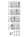
まず、本発明の第1の実施の形態を図面を参照して説明する。図1〜図8は、本発明の第1の実施の形態の階調表示方法を説明するための図である。本実施の形態における階調表示方法は、8ビットすなわち256階調の画像を表示する場合の例である。図1はサブフィールドの構成図であり、図2は階調に対してどのセグメントが点灯するかを示す表であり、図3〜図8は各セグメントに於いて階調に対してどのサブフィールドが点灯するかを示す表であり、各サブフィールドの対応する場所に、そのサブフィールドが有する時間長を示す文字が記入されている場合は、そのサブフィールドが点灯している(オンである)ことを示し、何も記入されていない場合は、そのサブフィールドが非点灯である(オフである)ことを示している。本実施の形態では従来例で示した図31と同様の投写型装置における階調表示方法に関するもので、1つのDMD素子を用いて、RGBで分割されたカラーフィルターを回転させて、赤色、緑色、青色のフィールドを順次表示し、カラー表示を得るものである。本実施の形態ではRGB均等な角度のカラーフィルターを1フィールド期間に6回転させるので、各色6セグメントの分離された発光期間(本発明の「時分割時間帯」に対応)を有する。さらに図1〜図8では緑色のサブフィールドの構成図のみを示すものであるが、セグメント1から6までの各セグメントの時間は等しく、また各セグメント間はRとBのそれぞれ1セグメント分の間隔が空いている。
【0024】
図1では従来例で説明した図29と同じように、各サブフィールドの時間長は、当該サブフィールドのみをオンとした場合の1つの色の輝度に対応する重みづけがされており、この重みづけは、図31の構成の場合においては、DMDのミラーがオン(点灯)している時間に対応するもの、あるいは、この時間長内での点灯するパルス数に対応するものである。本実施の形態では1フィールドを36サブフィールドを用いて表示し、8ビット「256」階調を6つのセグメントにほぼ均等に配分し、それぞれセグメント1からセグメント6までを「42t」、「43t」、「42t」、「43t」、「42t」、「43t」の時間長を有するように配分している。ここでtは緑色が1フィールド時間に表示される時間を256階調で割った基本時間(本発明の「一単位」に対応)を示す。
【0025】
本実施の形態においては、図2に示すように、「0」から「42」階調まではセグメント1内のサブフィールドを用いて表示を行い(その際、他のセグメントのサブフィールドは全て非点灯(オフ))、さらに「43」から「86」階調まではセグメント2内のサブフィールドを用いて階調表示を行う(その際セグメント1は全てのサブフィールドを常時点灯(オン)とし、セグメント3以降のサブフィールドは全て非点灯)、といった具合に順番にセグメント毎にある階調までの表示を完了させ、続いて次のセグメントにて次の階調までの表示を行い、連続的な時間幅変調で表示を行うものである。
【0026】
図3〜図8に示すように、各セグメント内では、「42t」(または「43t」)の時間長を、それぞれ「11t」(または「12t」)、「16t」、「8t」、「4t」、「2t」、「1t」の時間長を有するサブフィールド6個に分割し、これらのサブフィールドのオン/オフの組合せによって、当該セグメントが担当する階調の変化分を表示する。セグメント1を例に挙げて説明すると、「0」から「42」の階調のうち、「0」から「31」までを「16t」、「8t」、「4t」、「2t」、「1t」の時間長を有するサブフィールド5個で2進法に従って表示する。「32」から「42」間での階調は「11t」と「16t」の時間長を有する2つのサブフィールドを常に点灯させ、残りを「8t」、「4t」、「2t」、「1t」の時間長を有するサブフィールド4個で2進法に従って表示する。セグメント2〜セグメント6についても、同様に、各セグメントを構成するサブフィールドのオン/オフの組合せによって、当該セグメントが担当する階調の変化分を表示する。なお、「11t」および「12t」の時間長を有するサブフィールドは、本発明の「調整サブフィールド」に対応し、「16t」、「8t」、「4t」、「2t」および「1t」の時間長を有するサブフィールドは、本発明の「2進法サブフィールド」に対応するものである。
【0027】
すなわち、階調が42(または43)増えるごとにセグメント1からセグメント6まで順番にそのセグメント内のサブフィールドが点灯するように連続的に増えて行き、各セグメント内ではそのセグメント内で完了するようにサブフィールドが概ね2進法に従って点灯していくように表示する。
【0028】
図9は移動するランプ波形を、本実施の形態における階調表示方法で表示したときに見える画像を、コンピュータでシミュレーションしたものである。シミュレーションの方法は従来例で説明した方法と同様で、毎フィールド表示期間中に8画素の速度で左の方向に動かしたときの、目の時間的な積分量を計算したものである。図9の波形は図32の波形と比較して、階調が「127」から「128」、あるいは「63」から「64」の画素に視線が変化するとき、すなわち2進法表示で新たなビットが立つ場所でのノイズが大幅に軽減していることがわかる。これにより、動画での疑似輪郭状の画質劣化は大きく改善される。
【0029】
本実施の形態の形態では緑色のサブフィールドを例に挙げて説明したが、赤色、緑色についても同様の方法で、動画での画質劣化は大きく改善されることは言うまでもない。
【0030】
また本実施の形態の形態では、各セグメントのサブフィールドの構成を「11t」(または「12t」)、「16t」、「8t」、「4t」、「2t」、「1t」の時間長を有する6サブフィールドとしたが、「8t」、「4t」、「2t」、「1t」は同じで、残りの「27t」(または「28t」)を「10t」と「17t」、または「13t」と「14t」などどのような重み付けで2つのサブフィールドに分けてもほとんど同じ効果を示す。ただし、1つのセグメント内で当該セグメントが担当する階調の変化分の一部が表現できなくなる様なサブフィールドは、除外するものとする。本実施の形態のように、「42t」の時間長を有するセグメントを例にとると、本発明の2進法サブフィールドを「8t」、「4t」、「2t」、「1t」の時間長を有する4サブフィールドとし、本発明の調整サブフィールドに対応するサブフィールドの組合せが、「22t」と「5t」の組合せのように、2つのサブフィールドの時間長差が「16t」より大きくなるようなサブフィールド構成が、上記除外される構成に相当する。
【0031】
本実施の形態の形態では図33に示すようなRGB均等な角度のカラーフィルターを1フィールド期間に6回転させるとしたが、これに限定されるものではなく、図34に示すようなRGBRGBと均等に6分割されたカラーフィルターを1フィールドに3回転させても同じことであるし、さらにはRGBRGBRGBと9分割されたカラーフィルターを1フィールドに2回転、さらにはRGB・・・RGBと18分割されたカラーフィルタを1フィールドに1回転させても同じことである。
【0032】
(第2の実施の形態)
次に、本発明の第2の実施の形態を図面を参照して説明する。図10〜図13は、本発明の第2の実施の形態の階調表示方法を説明するための図である。本実施の形態における階調表示方法も、第1の実施の形態における階調表示方法と同様に、8ビットすなわち256階調の画像を表示する場合の例である。図10はサブフィールドの構成図であり、図11は階調に対してどのセグメントが点灯するかを示す表であり、図12、図13は各セグメントに於いて階調に対してどのサブフィールドが点灯するかを示す表であり、各サブフィールドの対応する場所に、そのサブフィールドが有する時間長を示す文字が記入されている場合は、そのサブフィールドが点灯している(オンである)ことを示し、何も記入されていない場合は、そのサブフィールドが非点灯である(オフである)ことを示している。本実施の形態では従来例で説明した図31と同様に、1つのDMD素子を用いて、RGBで分割されたカラーフィルターを回転させて、赤色、緑色、青色のフィールドを順次表示し、カラー表示を得るものである。本実施の形態では図35に示すようなRGBRGBと6分割されたカラーフィルターを1フィールド期間に3回転させるので、各色6セグメントの分離された発光期間(本発明の「時分割時間帯」に対応)を有する。本実施の形態における階調表示方法に用いるカラーフィルターは、図35に示すように、緑色のG1の部分とG2の部分で角度に差がある。さらに図10〜図13では緑色のサブフィールドの構成図のみを示すものであるが、セグメント1から6までの各セグメントの時間はこのカラーフィルタの角度に応じて時間の差がある。
【0033】
図10では従来例で説明した図29と同じように、各サブフィールドの時間長は、当該サブフィールドのみをオンとした場合の1つの色の輝度に対応する重みづけがされており、この重みづけは、図31の構成の場合においては、DMDのミラーがオン(点灯)している時間に対応するもの、あるいは、この時間長内での点灯するパルス数に対応するものである。本実施の形態では1フィールドを33サブフィールドを用いて表示し、8ビット「256」階調を6つのセグメントの時間に比例するように配分し、それぞれセグメント1からセグメント6までを「31t」、「54t」、「31t」、「55t」、「31t」、「54t」の時間長を有するように配分している。ここでtは緑色が1フィールド時間に表示される時間を256階調で割った基本時間(本発明の「一単位」に対応)を示す。
【0034】
本実施の形態においては、図11に示すように、「0」から「31」階調まではセグメント1内のサブフィールドを用いて表示を行い(その際他のセグメントのサブフィールドは全て非点灯(オフ))、さらに「32」から「85」階調まではセグメント2内のサブフィールドを用いて階調表示を行う(その際セグメント1は全てのサブフィールドが常時点灯(オン)し、セグメント3以降のサブフィールドは全て非点灯)といった具合に、順次セグメント毎にある階調までの表示を完了させ、続いて次のセグメントにて次の階調までの表示を行い、連続的な時間幅変調で表示を行うものである。
【0035】
図12に示すように、短い時間長を有するセグメント1、3、5では、「31t」の時間長を、それぞれ「16t」、「8t」、「4t」、「2t」、「1t」の時間長を有するサブフィールド5個に分割し、これらのサブフィールドのオン/オフの組合せを2進法にしたがって行うことによって、当該セグメントが担当する階調の変化分を表示する。すなわち、セグメント1、3、5は、本発明の「2進法サブフィールド」に対応するサブフィールドのみで構成されている。
【0036】
また、図13に示すように、長い時間長を有するセグメント2、4、6では、「54t」の時間長をそれぞれ「23t」、「16t」、「8t」、「4t」、「2t」、「1t」の時間長を有するサブフィールド6個に分割し、これらのサブフィールドのオン/オフの組合せによって、当該セグメントが担当する階調の変化分を表示する。セグメント2を例に挙げて説明すると、「32」から「85」の階調のうち、「32」から「63」までを「16t」、「8t」、「4t」、「2t」、「1t」の時間長を有するサブフィールド5個で2進法に従って表示する。「63」から「85」間での階調は「23t」と「16t」の重みの2つのサブフィールドを常に点灯させ、残りを「8t」、「4t」、「2t」、「1t」の時間長を有するサブフィールド4個で2進法に従って表示する。セグメント4およびセグメント6についても、同様に、各セグメントを構成するサブフィールドのオン/オフの組合せによって、当該セグメントが担当する階調の変化分を表示する。なお、セグメント2、4、6において、「23t」の時間長を有するサブフィールドは、本発明の「調整サブフィールド」に対応し、「16t」、「8t」、「4t」、「2t」および「1t」の時間長を有するサブフィールドは、本発明の「2進法サブフィールド」に対応するものである。
【0037】
すなわち、階調が31(または54)増えるごとにセグメント1からセグメント6まで順番にそのセグメント内のサブフィールドが点灯するように連続的に増えて行き、各セグメント内ではそのセグメント内で完了するようにサブフィールドが概ね2進法に従って点灯していくように表示する。このようにしてもほぼ第1の実施の形態と同等の効果が期待できる。
【0038】
なお、カラーフィルターとセグメント構成(サブフィールド構成)の関係は、図35に示したカラーフィルターと図10に示したセグメント構成(サブフィールド構成)の関係に限るものではなく、カラーフィルターの分割に対応して、セグメント分割が行われており、オンのサブフィールドとオフのサブフィールドとが混在するセグメントの数を、0または1とし、残りの各セグメントを、オンのサブフィールドのみ、または、オフのサブフィールドのみとなるように構成し、連続した階調の表示切換を行う場合、同一のセグメント内でのサブフィールドのオン/オフ切換によって行うことを優先し、1階調差の表示切換を行う場合、表示切換前にオンのサブフィールドとオフのサブフィールドとが混在するセグメントの数が0となっている場合を除き、複数のサブフィールドで構成されるセグメントについては、オンのサブフィールドのみで構成されたセグメントを、オフのサブフィールドのみで構成されるようにする切換、および、オフのサブフィールドのみで構成されたセグメントを、オンのサブフィールドのみで構成されるようにする切換は行わないような、セグメント構成(サブフィールド構成)になっておればよい。
【0039】
(第3の実施の形態)
次に、本発明の第3の実施の形態を図面を参照して説明する。図14〜図17は、本発明の第3実施の形態の階調表示方法を説明するための図である。本実施の形態における階調表示方法も、第1の実施の形態における階調表示方法と同様に、8ビットすなわち256階調の画像を表示する場合の例である。図14はサブフィールドの構成図であり、図15は階調に対してどのセグメントが点灯するかを示す表であ、図16、図17は各セグメントにおいて階調に対してどのサブフィールドが点灯するかを示す表であり、各サブフィールドの対応する場所に、そのサブフィールドが有する時間長を示す文字が記入されている場合は、そのサブフィールドが点灯している(オンである)ことを示し、何も記入されていない場合は、そのサブフィールドが非点灯である(オフである)ことを示している。本実施の形態では従来例で説明した図31と同様に、1つのDMD素子を用いて、RGBで分割されたカラーフィルターを回転させて、赤色、緑色、青色のフィールドを順次表示し、カラー表示を得るものである。本実施の形態ではRGB均等な角度のカラーフィルターを1フィールド期間に8回転させるので、各色8セグメントの分離された発光期間(本発明の「時分割時間帯」に対応)を有する。さらに図14〜図17には緑色のサブフィールドの構成図のみを示すが、セグメント1から8までの各セグメントの時間は等しく、また各セグメント間はRとBのそれぞれ1セグメント分の間隔が空いている。
【0040】
図14では従来例で説明した図29と同じように、各サブフィールドの時間長は、当該サブフィールドのみをオンとした場合の1つの色の輝度に対応する重みづけがされており、この重みづけは、図31の構成の場合においては、DMDのミラーがオン(点灯)している時間に対応するもの、あるいは、この時間長内での点灯するパルス数に対応するものである。本実施の形態では1フィールドを47サブフィールドを用いて表示し、8ビット「256」階調を、それぞれセグメント1からセグメント7までを「32t」の時間長を有するように、セグメント8を「31t」の時間長を有するように配分している。ここでtは緑色が1フィールド時間に表示される時間を256階調で割った基本時間(本発明の「一単位」に対応)を示す。
【0041】
本実施の形態においては、図15に示すように、「0」から「32」階調まではセグメント1内のサブフィールドを用いて表示を行い(その際他のセグメントのサブフィールドは全て非点灯(オフ))、さらに「33」から「64」階調まではセグメント2内のサブフィールドを用いて表示を行う(その際セグメント1は全てのサブフィールドが常時点灯(オン)し、セグメント3以降のサブフィールドは全て非点灯)といった具合に、順次セグメント毎にある階調までの表示を完了させ、続いて次のセグメントにて次の階調までの表示を行い、連続的な時間幅変調で表示を行う点では第1の実施の形態と同様である。
【0042】
図16に示すように、セグメント8を除く各セグメント内では、「32t」の時間長のうち、「31t」の時間長をそれぞれ「16t」、「8t」、「4t」、「2t」、「1t」の時間長を有するサブフィールド5個に分割し、これらのサブフィールドのオン/オフの組合せを2進法にしたがって行うことによって、当該セグメントが担当する階調の変化分を表示する。さらに最後に最小ビットである「1t」の時間長を有するサブフィールドを点灯させることにより「32t」の時間長に対応する輝度を表現することが可能になる。このようにセグメント1からセグメント7まで連続的に「32」階調毎に、各セグメントを構成するサブフィールドのオン/オフの組合せによって、当該セグメントが担当する階調の変化分を表示する。なお、上記各セグメントにおいて、最後に点灯させる「1t」の時間長を有するサブフィールドは、本発明の「調整サブフィールド」に対応し、残りの「16t」、「8t」、「4t」、「2t」および「1t」の時間長を有するサブフィールドは、本発明の「2進法サブフィールド」に対応するものである。
【0043】
但し、最後の「225」から「255」階調までの表示については、図17に示すように、セグメント8内で、「31t」の時間長を、それぞれ「16t」、「8t」、「4t」、「2t」、「1t」の時間長を有するサブフィールド5個で2進法に従って表示する。すなわち、セグメント8は、本発明の「2進法サブフィールド」に対応するサブフィールドのみで構成されている。
【0044】
すなわち、階調が32増えるごとにセグメント1からセグメント8まで順番にそのセグメント内のサブフィールドが点灯するように連続的に増えて行き、各セグメント内ではそのセグメント内で完了するようにサブフィールドが2進法に従って点灯していくように表示する。
【0045】
本実施の形態においては、階調を連続的に増加する場合に、セグメント内でのサブフィールドの点灯は、セグメント1〜7の最後に点灯する「1t」の時間長を有するサブフィールドの点灯を除き、2進法にしたがって行われるので、構成がシンプルになる。
【0046】
(第4の実施の形態)
次に、本発明の第4の実施の形態を図面を参照して説明する。図18〜図21は、本発明の第4の実施の形態の階調表示方法を説明するための図である。本実施の形態における階調表示方法も、第1の実施の形態における階調表示方法と同様に、8ビットすなわち256階調の画像を表示する場合の例である。図18はサブフィールドの構成図であり、図19は階調に対してどのセグメントが点灯するかを示す表であり、図20、図21は各セグメントに於いて階調に対してどのサブフィールドが点灯するかを示す表であり、各サブフィールドの対応する場所に、そのサブフィールドが有する時間長を示す文字が記入されている場合は、そのサブフィールドが点灯している(オンである)ことを示し、何も記入されていない場合は、そのサブフィールドが非点灯である(オフである)ことを示している。本実施の形態では従来例で説明した図31と同様に、1つのDMD素子を用いて、RGBで分割されたカラーフィルターを回転させて、赤色、緑色、青色のフィールドを順次表示し、カラー表示を得るものである。本実施の形態ではRGB均等な角度のカラーフィルターを1フィールド期間に4回転させるので、各色4セグメントの分離された発光期間(本発明の「時分割時間帯」に対応)を有する。さらに図18〜図21には緑色のサブフィールドの構成図のみを示すが、セグメント1から4までの各セグメントの時間は等しく、また各セグメント間はRとBのそれぞれ1セグメント分の間隔が空いている。
【0047】
図18では従来例で説明した図29と同じように、各サブフィールドの時間長は、当該サブフィールドのみをオンとした場合の1つの色の輝度に対応する重みづけがされており、この重みづけは、図31の構成の場合においては、DMDのミラーがオン(点灯)している時間に対応するもの、あるいは、この時間長内での点灯するパルス数に対応するものである。本実施の形態では1フィールドを27サブフィールドを用いて表示し、8ビット「256」階調を、それぞれセグメント1からセグメント3までを「64t」の時間長を有するように、セグメント4を「63t」の時間長を有するように配分している。ここでtは緑色が1フィールド時間に表示される時間を256階調で割った基本時間(本発明の「一単位」に対応)を示す。
【0048】
本実施の形態においては、図19に示すように、「0」から「64」階調まではセグメント1内のサブフィールドを用いて表示を行い(その際他のセグメントのサブフィールドは全て非点灯(オフ))、さらに「65」から「128」階調まではセグメント2内のサブフィールドを用いて表示を行う(その際セグメント1は全てのサブフィールドが常時点灯(オン)し、セグメント3以降のサブフィールドは全て非点灯)といった具合に、セグメント毎にある階調までの表示を完了させ、続いて次のセグメントにて次の階調までの表示を行い、連続的な時間幅変調で表示を行う点では第1の実施の形態と同様である。
【0049】
図20に示すように、セグメント4を除く各セグメント内では、「64t」の時間長のうち、「63t」の時間長をそれぞれ「32t」、「16t」、「8t」、「4t」、「2t」、「1t」の時間長を有するサブフィールド6個に分割し、これらのサブフィールドのオン/オフの組合せを2進法にしたがって行うことによって、当該セグメントが担当する階調の変化分を表示する。さらに最後に最小ビットである「1t」の時間長を有するサブフィールドを点灯させることにより「64t」の時間長に対応する輝度を表現することが可能になる。このようにセグメント1からセグメント3まで連続的に「64」階調毎に、各セグメントを構成するサブフィールドのオン/オフの組合せによって、当該セグメントが担当する階調の変化分を表示する。なお、上記各セグメントにおいて、最後に点灯させる「1t」の時間長を有するサブフィールドは、本発明の「調整サブフィールド」に対応し、残りの「32t」、「16t」、「8t」、「4t」、「2t」および「1t」の時間長を有するサブフィールドは、本発明の「2進法サブフィールド」に対応するものである。
【0050】
但し、最後の「193」から「255」階調までの表示については、図21に示すように、セグメント4内で、「63t」の時間長を、それぞれ「32t」、「16t」、「8t」、「4t」、「2t」、「1t」の時間長を有するサブフィールド5個で2進法に従って表示する。すなわち、セグメント4は、本発明の「2進法サブフィールド」に対応するサブフィールドのみで構成されている。
【0051】
すなわち、階調が64増えるごとにセグメント1からセグメント4まで順番にそのセグメント内のサブフィールドが点灯するように連続的に増えて行き、各セグメント内ではそのセグメント内で完了するようにサブフィールドが2進法に従って点灯していくように表示する。
【0052】
本実施の形態においても、第3の実施の形態と同様に、階調を連続的に増加する場合に、セグメント内でのサブフィールドの点灯は、セグメント1〜3の最後に点灯する「1t」の時間長を有するサブフィールドの点灯を除き、2進法にしたがって行われるので、構成がシンプルになる。
【0053】
(第5の実施の形態)
次に、本発明の第5の実施の形態を図面を参照して説明する。図22は、本発明の第5の実施の形態の階調表示方法を説明するための図である。本実施の形態において、特に説明のないものについては、第1の実施の形態と同じとする。図22は階調に対してどのセグメントが点灯するかを示す表である。本実施の形態では各セグメントのサブフィールド構成は第1の実施の形態で説明した図1と同様であるが、本実施の形態では、「0」から「42」階調まではセグメント6内のサブフィールドを用いて表示を行い(その際他のセグメントのサブフィールドは全て非点灯)、さらに「43」から「86」階調まではセグメント5内のサブフィールドを用いて階調表示を行う(その際セグメント6は全てのサブフィールドが常時点灯し、セグメント1から4のサブフィールドは全て非点灯)といった具合に、セグメント間における階調の連続性の時間軸が、第1の実施の形態のものと正反対になっている。
【0054】
このように、セグメント間における階調の連続性の時間軸を正反対にしても、動画像の疑似輪郭を抑制する効果は同等に得られる。このことは第1の実施の形態のみならず、第2〜第4の実施の形態についても適用できる。
【0055】
(第6の実施の形態)
次に、本発明の第6の実施の形態を図面を参照して説明する。図23は、本発明の第6の実施の形態の階調表示方法を説明するための図である。本実施の形態において、特に説明のないものについては、第1の実施の形態と同じとする。図23は階調に対してどのセグメントが点灯するかを示す表である。本実施の形態では各セグメントのサブフィールド構成は第1の実施の形態で説明した図1と同様であるが、本実施の形態では「0」から「42」階調まではセグメント1内のサブフィールドを用いて表示を行い(その際他のセグメントのサブフィールドは全て非点灯)、さらに「43」から「86」階調まではセグメント3内のサブフィールドを用いて階調表示を行う(その際セグメント1は全てのサブフィールドが常時点灯し、セグメント1と3以外のセグメントのサブフィールドは全て非点灯)といった具合に、セグメント毎にある階調までの表示を完了させる点はこれまでと同様であるが、セグメント間ではセグメントのオン/オフ切換の連続性は崩れている。すなわち、図23に示すように、階調が42(または43)増えるごとにセグメント1からセグメント6まで順不同にそのセグメント内のサブフィールドが点灯するように連続的に増えて行き、各セグメント内ではそのセグメント内で完了するようにサブフィールドが概ね2進法に従って点灯していくように表示する。また、表示切換前にオンのサブフィールドとオフのサブフィールドとが混在するセグメントの数が0となっている場合は、複数のサブフィールドで構成されるセグメントについては、オンのサブフィールドのみで構成されたセグメントを、オフのサブフィールドのみで構成されるようにする切換、および、オフのサブフィールドのみで構成されたセグメントを、オンのサブフィールドのみで構成されるようにする切換を行ってもよい。例えば、図23に示すように、「170」階調から「171」階調の表示切換を行う場合、「全てオフ」であったセグメント2を「全てオン」にし、「全てオン」であったセグメント6を「全てオフ」にしてもよい。つまり、セグメントのオン/オフ切換の順番は本実施の形態に因らず、いかなる順番であっても構わない。
【0056】
このように、セグメント間におけるセグメントのオン/オフ切換の連続性を崩しても、動画像の疑似輪郭を抑制する効果は同等に得られる。このことは第1の実施の形態のみならず、第2〜第5の実施の形態についても適用できる。但し、第1から第5の実施の形態における階調表示方法のセグメント選択要領のように(図2、図11、図15、図19、図22に示すように)、セグメント間におけるセグメントのオン/オフ切換の連続性を有する方が動画像のボケを抑制する効果がある。
【0057】
(第7の実施の形態)
次に、本発明の第7の実施の形態を図面を参照して説明する。図24〜図27は、本発明の第7の実施の形態の階調表示方法を説明するための図である。本実施の形態において、特に説明のないものについては、第1の実施の形態と同じとする。図24はサブフィールドの構成図であり、図25は階調に対してどのセグメントが点灯するかを示す表であり、図26、図27は各セグメントにおいて階調に対してどのサブフィールドが点灯するかを示す表であり、各サブフィールドの対応する場所に、そのサブフィールドが有する時間長を示す文字が記入されている場合は、そのサブフィールドが点灯している(オンである)ことを示し、何も記入されていない場合は、そのサブフィールドが非点灯である(オフである)ことを示している。本実施の形態では第1の実施の形態とセグメント数ならびにサブフィールド構成は同じであるが、セグメント内でのサブフィールドの時間的配列が異なる。
【0058】
本実施の形態では1フィールドを36サブフィールドを用いて表示し、8ビット「256」階調を6つのセグメントにほぼ均等に配分し、図25に示すように「0」から「42」階調まではセグメント1内のサブフィールドを用いて表示を行い(その際他のセグメントのサブフィールドは全て非点灯(オフ))、さらに「43」から「86」階調まではセグメント2内のサブフィールドを用いて階調表示を行う(その際セグメント1は全てのサブフィールドが常時点灯(オン)し、セグメント3以降のサブフィールドは全て非点灯)といった具合に、セグメント毎にある階調までの表示を完了させ、続いて次のセグメントにて次の階調までの表示を行い、連続的な時間幅変調で表示を行う点は第1の実施の形態と同様である。
【0059】
各セグメント内では「42t」(または「43t」)の時間長を、それぞれ「11t」(または「12t」)、「16t」、「8t」、「4t」、「2t」、「1t」の時間長を有するサブフィールド6個に分割し、これらのサブフィールドのオン/オフの組合せによって、当該セグメントが担当する階調の変化分を表示する点も第1の実施の形態と同様である。
【0060】
しかしながら本実施の形態では、1つのセグメント内のサブフィールドの時間的配列が時間長の短いサブフィールドから順番に「1t」−「2t」−「4t」−「8t」−「16t」−「11t」のように並んでいる。このように、セグメント内での時間的配列を特定しなくとも、動画像の疑似輪郭を抑制する効果は得られるが、本発明の第1の実施の形態のように、「2t」−「16t」−「4t」−「8t」−「11t」−「1t」のように、時間長の短いサブフィールドである「2t」と「1t」の時間長を有するサブフィールドをセグメントの最初と最後に配置し、次に時間長の短いサブフィールドである「4t」の時間長を有するサブフィールドを他の時間長の短いサブフィールドである「2t」、「1t」の時間長を有するサブフィールドと連続しないように配置するほうが、以下に説明する問題を回避できる。
【0061】
この問題は、文献(「10.4:Phased Reset Timing for Improved Digital Micromirror Device(DMD) Brightness」 SID 98 DIGEST pp.125-128)において、DMD素子の書き込みデータのロード/リセットに関する問題として説明されているものである。すなわち、1tよりも十分に短いロードタイムであればサブフィールドの時間的配列はどのようであっても、前のサブフィールドを表示している間に次のサブフィールドのデータをロードできるので問題ないが、例えばロードタイムより短い時間長を有するサブフィールドが来る場合に次のサブフィールドのデータをロードする時間が充分に与えられないという問題が起こる。この問題を解決するために短い時間長を有するサブフィールドをセグメントの最初と最後に配列すればよい。なぜならばセグメントの最初はその直前にスポークタイムという色の切り替わりによる強制非点灯時間が設けられるために、この間にセグメントの最初のサブフィールドのデータのロード/リセットが可能となる。またセグメントの最後もその直後にスポークタイムが来るので次のサブフィールドのデータをロードする必要がないからである。
【0062】
図28にリセットグループが4相のフェーズリセットを用いた場合のデータのロード/リセットを示す。これより、第1の実施の形態においては、データのロードタイムより短い時間長を有するサブフィールドがあっても、充分にデータのロード/リセットが可能であることがわかる。
【0063】
上記説明においては、「4t」、「2t」、「1t」の時間長を有するサブフィールドを、時間的に連続して配置しない、「2t」、「1t」の時間長を有するサブフィールドを、時間的に各セグメントの両端に配置するとして説明したが、一般的には、サブフィールドのデータのロードタイムの2倍より短い時間長を有するサブフィールドに対して、このような措置を講ずれば、上述したような問題は回避できる。
【0064】
なお、第1〜第7の実施の形態においては、赤色、緑色、青色についての256階調を例として説明したが、これに限るものではなく、他の色、他の階調数についても、本発明の階調表示方法は適用できるものである。また、本発明の各サブフィールドは、1フレーム内の所定の色に対応する時間を階調数で割った時間を一単位とし、当該サブフィールドのみをオンとした場合に得られる前記所定の1つの色の輝度に対応する時間長を有しているとして説明したが、これに限るものではなく、別の重みづけによるものであっても、当該サブフィールドのみをオンとした場合に所望の輝度が得られるようなものであればよい。要するに、1フレーム/フィールド内での所定の1つの色に対応する時間帯を複数の時分割時間帯で構成し、前記各時分割時間帯に対応する時間的なセグメントを設定し、前記各セグメントを1つ以上のサブフィールドで構成し、前記所定の1つの色の階調を、前記所定の1つの色の前記各サブフィールドのオン/オフを適宜指定することによって、表示させるものであれば、オンの前記サブフィールドとオフの前記サブフィールドとが混在する前記セグメントの数を、0または1とし、残りの前記各セグメントを、オンの前記サブフィールドのみ、または、オフの前記サブフィールドのみとなるように構成し、連続した階調の表示切換を行う場合、同一の前記セグメント内での前記サブフィールドのオン/オフ切換によって行うことを優先し、1階調差の表示切換を行う場合、表示切換前にオンの前記サブフィールドとオフの前記サブフィールドとが混在する前記セグメントの数が0となっている場合を除き、複数の前記サブフィールドで構成される前記セグメントについては、オンの前記サブフィールドのみで構成された前記セグメントを、オフの前記サブフィールドのみで構成されるようにする切換、および、オフの前記サブフィールドのみで構成された前記セグメントを、オンの前記サブフィールドのみで構成されるようにする切換は行わないような構成とすることによって、本発明の階調表示方法は適用できるものである。また、本発明において、図33、図34、図35に示したカラーフィルターは一例であり、本発明はカラーフィルターの形状には依存しない。例えば、図35に示すように、RGBのフィルタの角度は均等である必要はなく、色の配置も各図の配置に限定するものではない。また、RGBの色セグメント数についても同様であり、本発明では、RGB各色6セグメントや各色4セグメント、各色8セグメントなどの場合を例に挙げたが、これに限定するものではない。各実施の形態で述べたように、例えば、 1 フィールド期間にセグメント数分回転させることで、他のセグメント数にも対応でき、 1 フィールドに5回転させれば、RGB各色5セグメントとなる。本発明で最も重要なのは、各実施の形態で述べたように、各色セグメントにおいて、1つのセグメント内で順番にサブフィールドが点灯し、各セグメント内にて完了し、セグメント単位にて順次、連続的に点灯するように組まれたシーケンスであることである。
【0065】
【発明の効果】
以上説明したところから明らかなように、本発明は、サブフィールド法を用いた場合の動画像の画質劣化を、コスト増を抑制しつつ、防止できる階調表示方法を提供することができる。
【0066】
すなわち、本発明の階調表示方法によれば、視線の移動による誤ったサブフィールドの加算による異常な画像の発生を防ぎ、動画像の画質を向上させることができる。
【0067】
さらにDMDを用いた表示においてはデータのロードタイムの制約が緩く、容易に実施できるサブフィールドの時間的配列が可能になる。
【図面の簡単な説明】
【図1】本発明の第1の実施の形態における階調表示方法のサブフィールド構成図である。
【図2】本発明の第1の実施の形態における階調表示方法のセグメント選択表である。
【図3】本発明の第1の実施の形態における階調表示方法の0〜42階調でのサブフィールド選択表である。
【図4】本発明の第1の実施の形態における階調表示方法の43〜85階調でのサブフィールド選択表である。
【図5】本発明の第1の実施の形態における階調表示方法の86〜127階調でのサブフィールド選択表である。
【図6】本発明の第1の実施の形態における階調表示方法の128〜170階調でのサブフィールド選択表である。
【図7】本発明の第1の実施の形態における階調表示方法の171〜212階調でのサブフィールド選択表である。
【図8】本発明の第1の実施の形態における階調表示方法の213〜255階調でのサブフィールド選択表である。
【図9】本発明の第1の実施の形態における階調表示方法でランプ波形を移動したときに見える画像のシミュレーション結果を示す図である。
【図10】本発明の第2の実施の形態における階調表示方法のサブフィールド構成図である。
【図11】本発明の第2の実施の形態における階調表示方法のセグメント選択表である。
【図12】本発明の第2の実施の形態における階調表示方法のセグメント1、3、5でのサブフィールド選択表である。
【図13】本発明の第2の実施の形態における階調表示方法のセグメント2、4、6でのサブフィールド選択表である。
【図14】本発明の第3の実施の形態における階調表示方法のサブフィールド構成図である。
【図15】本発明の第3の実施の形態における階調表示方法のセグメント選択表である。
【図16】本発明の第3の実施の形態における階調表示方法のセグメント1〜7でのサブフィールド選択表である。
【図17】本発明の第3の実施の形態における階調表示方法のセグメント8でのサブフィールド選択表である。
【図18】本発明の第4の実施の形態における階調表示方法のサブフィールド構成図である。
【図19】本発明の第4の実施の形態における階調表示方法のセグメント選択表である。
【図20】本発明の第4の実施の形態における階調表示方法のセグメント1〜3でのサブフィールド選択表である。
【図21】本発明の第4の実施の形態における階調表示方法のセグメント4でのサブフィールド選択表である。
【図22】本発明の第5の実施の形態における階調表示方法のセグメント選択表である。
【図23】本発明の第6の実施の形態における階調表示方法のセグメント選択表である。
【図24】本発明の第7の実施の形態における階調表示方法のサブフィールド構成図である。
【図25】本発明の第7の実施の形態における階調表示方法のセグメント選択表である。
【図26】本発明の第7の実施の形態における階調表示方法のセグメント1、3、5でのサブフィールド選択表である。
【図27】本発明の第7の実施の形態における階調表示方法のセグメント2、4、6でのサブフィールド選択表である。
【図28】本発明の階調表示方法の第1の実施の形態におけるデータロード/リセットの操作を示す図である。
【図29】従来の階調表示方法におけるサブフィールド構成図である。
【図30】従来の階調表示方法におけるサブフィールド選択表である。
【図31】DMDを用いた投写表示装置の構成図である。
【図32】従来の階調表示方法でランプ波形を移動したときに見える画像のシミュレーション結果を示す図である。
【図33】本発明の第1の実施の形態における階調表示方法に用いるカラーフィルターの概略図である。
【図34】本発明の第1の実施の形態における階調表示方法に用いるカラーフィルターの変形例の概略図である。
【図35】本発明の第2の実施の形態における階調表示方法に用いるカラーフィルターの概略図である。
【図36】従来の階調表示方法で階調を表示している画素間での視点の移動を示す図である。
【符号の説明】
11 DMD素子
12 カラーフィルタ
13 ランプ
14 投写レンズ[0001]
BACKGROUND OF THE INVENTION
The present invention has a binary memory, such as a plasma display panel (hereinafter referred to as PDP (Plasma Display panel)) and DMD (Digital Micromirror Device), and a plurality of binary values each weighted with a moving image having halftones. The present invention relates to a gradation display method for a display device using the so-called subfield method, in which the above images are displayed in a time-overlapping manner.
[0002]
[Prior art]
The conventional so-called subfield method is used to display a halftone image on a display device having a binary (on / off) memory effect, as disclosed in Japanese Patent Laid-Open No. Hei 4-195087. It is. 29 and 30 show examples of this display method. This uses a single DMD element and a rotating color filter as shown in FIG. 31 to display red, green, and blue sequentially to display a color display and an 8-bit, 256-level television image. It is an example.
[0003]
In FIG. 31, 1 is a DMD element, 2 is a disk-shaped color filter, 3 is a lamp, and 4 is a projection lens. The
[0004]
In this conventional example, one image (one field) is composed of eight binary images (subfields). The time length of each subfield shown in FIG. 29 is weighted corresponding to the luminance of one color when only the subfield is turned on, and this weighting is in the case of the configuration of FIG. , Corresponding to the time when the mirror of the DMD is on (lit), or corresponding to the number of pulses to be lit within this time length. In the example of FIG. 29 and FIG. 30, each subfield is “1”, “2”, “4”, “8”, “16”, “32”, “64”, “64”, respectively, according to the binary system. 128 "(luminance). That is, each subfield has a unit time length t that is “1”, “2”, “4”, “8”, “16”, “32”, “64”, “128” times longer. have. As shown in FIG. 30, each pixel of the DMD displays halftones depending on the combination of which subfield is lit. For example, the luminance corresponding to “173” has a
[0005]
Since the line of sight is almost fixed in the still image, subfield addition is normally performed in each pixel, so there is no deterioration in image quality. By adopting such a driving method, gradation display is possible even with an element that can take only binary values, such as a mirror, such as a mirror.
[0006]
[Problems to be solved by the invention]
However, in the conventional display method using the subfield method, the literature (“Pseudo contour noise seen in pulse width modulation video display”: Television Society Technical Report, Vol.19, No.2, IDY95-21, pp. As shown in .61-66), there is a problem that a unique pseudo-contour noise is seen in the moving image and the image quality is deteriorated. This is because the eye follows the moving image, and the temporal integration region of the eye changes spatially. That is, when the line of sight moves at a speed of moving a plurality of pixels within one field display period, the subfield addition is performed not over one pixel but over a plurality of pixels, and a normal image cannot be obtained. Deteriorates.
[0007]
FIG. 36 is a diagram illustrating the case where the above problem is extreme, taking the gradation display method shown in FIGS. 29 and 30 as an example. Pixel A and pixel B are arranged adjacent to each other, and display 127 gradations and 128 gradations in the gradation display method shown in FIGS. 29 and 30, respectively. That is, the pixel A has 1sf to 7sf on and only 8sf is off, and the pixel B has 1sf to 7sf off and only 8sf is on. In FIG. 36, the arrangement direction of the pixels is shown as the vertical direction, and the arrangement direction of the subfields is shown as the horizontal direction. That is, the vertical direction in FIG. 36 indicates the spatial movement of the viewpoint, and the horizontal direction indicates the temporal movement of the viewpoint. Here, if the viewpoint does not move from the pixel A (arrow c), the integral value of one field of the pixel A is 127 gradations as displayed. However, when the viewpoint is moved from the pixel A to the pixel B at the speed of two pixels in one field (arrow a), the integrated values of the pixel A and the pixel B are both regarded as 255 gradations. In addition, when the viewpoint is moved from the pixel B to the pixel A at the speed of two pixels in one field (arrow b), the integrated values of the pixel A and the pixel B are both regarded as 0 gradation.
[0008]
FIG. 32 is a computer simulation of an image that appears when a moving ramp waveform is displayed by a conventional subfield method in order to quantitatively measure the actual amount of image quality degradation. In this simulation method, the temporal integration amount of the eye when moving in the left direction at a speed of 8 pixels during each field display period is calculated.
[0009]
The ramp waveform is originally a straight diagonal line. However, in the conventional method, when the line of sight changes from a pixel having a gradation of “127” to “128” or “63” to “64”, that is, where a new bit is set in binary display, Noise is seen. In an actual image, this is a pseudo-contour image quality degradation.
[0010]
As described above, the gradation display by the conventional subfield method is unnatural when there is a considerable luminance difference between pixels that have almost no original luminance difference when the screen is observed following the movement of the image. There is a problem that it may be perceived.
[0011]
When trying to solve the above problem by the conventional subfield method, the subfield division is subdivided, and the time length of each subfield is minimized (in the gradation display method shown in FIGS. 29 and 30, “ 1t ") can be considered, but an increase in the number of subfields is directly linked to an increase in memory capacity and an accompanying increase in power consumption, etc. Cost increases. For this reason, it has been desired to realize a gradation display method capable of preventing image quality deterioration of a moving image while suppressing an increase in cost by suppressing an increase in the number of subfield divisions as much as possible.
[0012]
In consideration of the above-described problems of the conventional gradation display method, the present invention provides gradation display that can prevent deterioration in image quality of a moving image when the subfield method is used while suppressing an increase in cost. It is intended to provide a method.
[0013]
[Means for Solving the Problems]
In order to solve the above-mentioned problem, the first invention (corresponding to the invention described in claim 1) is to divide a time zone corresponding to a predetermined color within one frame / field into a plurality of time-division time zones. A time segment corresponding to each time-division time zone is set, each segment is composed of one or more subfields, and the gradation of the predetermined one color is set to the predetermined one In the gradation display method to be displayed by appropriately designating on / off of each subfield of one color, the number of the segments in which the on subfield and the off subfield are mixed is set to 0 or 1 When the remaining segments are configured so that only the subfields that are turned on or only the subfields that are turned off are to be displayed, and the continuous gradation display switching is performed, the same segment is selected. Priority is given to switching on / off of the subfields within the case, and when switching display of one gradation difference, the subfields that are on and the subfields that are off are mixed before display switching. Except for the case where the number of segments is 0, for the segment composed of a plurality of the subfields, the segment composed only of the subfield that is on is composed only of the subfield that is off. The gradation display method is characterized in that switching is not performed, and switching is not performed so that the segment configured only by the subfield that is off is configured only by the subfield that is on. .
[0014]
In the second aspect of the present invention (corresponding to the aspect of the present invention described in claim 2), when display switching of continuous gradation is performed, the segment to be switched on / off of the subfield is set as the segment time. The gradation display method according to the first aspect of the present invention is characterized in that selection is made according to a typical arrangement.
[0015]
In a third aspect of the present invention (corresponding to the present invention according to claim 3), each of the subfields turns on all the subfields corresponding to the predetermined one color in the one frame / field. A unit obtained by dividing the luminance obtained by the number of gradations as one unit, and having a weight corresponding to the luminance of the predetermined one color obtained when only the subfield is turned on, and the segment All or a part of each of the plurality of subfields is n + 1 (n is a predetermined natural number), and each one is the unit of 2021... 2nIn the binary subfield having the double weight, when the continuous gradation display is switched, the on / off switching of each binary subfield is performed by 2021... 2nThe gradation display method according to the first or second aspect of the present invention is characterized in that the priority is given in the order corresponding to.
[0016]
According to a fourth aspect of the present invention (corresponding to the aspect of the present invention described in claim 4), a part of the plurality of subfields for each segment is the subfield different from the binary subfield. When switching display of continuous gradations is performed in a field, ON / OFF switching between the binary subfields is performed in preference to ON / OFF switching of the adjustment subfield. 3 is a gradation display method according to the present invention.
[0017]
According to a fifth aspect of the present invention (corresponding to the present invention described in claim 5), each segment has only one adjustment subfield, and only one adjustment subfield has the one unit. The gradation display method according to the fourth aspect of the present invention is characterized in that the weight is one time as large as.
[0018]
According to a sixth aspect of the present invention (corresponding to the present invention described in claim 6), the weight is obtained by dividing the time corresponding to the predetermined one color in the one frame / field by the number of gradations. The gradation display method according to any one of the first to fifth aspects of the present invention, wherein the time length is one unit.
[0020]
First7The present invention (claims)7In the case where there is the subfield having the time length shorter than the load time of the data of each subfield, the time length shorter than twice the load time is set for each segment. And a subfield having a first subfield and / or a rearmost subfield.ofIt is the gradation display method of the present invention.
[0021]
With the above configuration, it is possible to prevent the occurrence of an abnormal image due to the addition of subfields due to movement of the line of sight while suppressing an increase in cost and to improve the quality of the moving image.
[0022]
DETAILED DESCRIPTION OF THE INVENTION
Embodiments of the present invention will be described below with reference to the drawings.
[0023]
(First embodiment)
First, a first embodiment of the present invention will be described with reference to the drawings. FIGS. 1-8 is a figure for demonstrating the gradation display method of the 1st Embodiment of this invention. The gradation display method in this embodiment is an example in the case of displaying an image of 8 bits, that is, 256 gradations. FIG. 1 is a configuration diagram of subfields, FIG. 2 is a table showing which segments are lit with respect to gradations, and FIGS. 3 to 8 show which subfields are for gradations in each segment. Is a table showing whether or not is lit, and when a character indicating the time length of the subfield is written at the corresponding position of each subfield, the subfield is lit (ON) If nothing is entered, it indicates that the subfield is not lit (off). The present embodiment relates to a gradation display method in a projection type apparatus similar to that shown in FIG. 31 shown in the conventional example. A single DMD element is used to rotate a color filter divided by RGB to obtain red, green, and green colors. The blue field is sequentially displayed to obtain a color display. In the present embodiment, the RGB color filter with an equal angle of RGB is rotated six times in one field period, so that it has a light emission period (corresponding to the “time division time zone” of the present invention) of 6 segments for each color. Further, FIGS. 1 to 8 show only the configuration diagram of the green subfield, but the time of each segment from
[0024]
In FIG. 1, as in FIG. 29 described in the conventional example, the time length of each subfield is weighted corresponding to the luminance of one color when only the subfield is turned on. In the case of the configuration of FIG. 31, it corresponds to the time during which the DMD mirror is on (lighted) or to the number of pulses to be lit within this time length. In the present embodiment, one field is displayed using 36 subfields, and 8-bit “256” gradation is distributed almost evenly to six segments, and
[0025]
In the present embodiment, as shown in FIG. 2, the display is performed using subfields in
[0026]
As shown in FIGS. 3 to 8, within each segment, the time length of “42t” (or “43t”) is set to “11t” (or “12t”), “16t”, “8t”, “4t”, respectively. ”,“ 2t ”, and“ 1t ”are subdivided into six subfields, and the change in gradation that the segment is responsible for is displayed by the on / off combination of these subfields. The
[0027]
That is, every time the gradation is increased by 42 (or 43), the subfields in the segment are sequentially increased from the
[0028]
FIG. 9 is a computer simulation of an image that appears when a moving ramp waveform is displayed by the gradation display method according to the present embodiment. The simulation method is the same as the method described in the conventional example, and calculates the temporal integration amount of the eye when moving in the left direction at a speed of 8 pixels during each field display period. Compared with the waveform of FIG. 32, the waveform of FIG. 9 is new when the line of sight changes from “127” to “128” or “63” to “64”. It can be seen that the noise at the place where the bit stands is greatly reduced. As a result, the image quality deterioration of the pseudo contour in the moving image is greatly improved.
[0029]
In the present embodiment, the green subfield has been described as an example, but it goes without saying that image quality degradation in moving images is greatly improved by the same method for red and green.
[0030]
In this embodiment, the subfield structure of each segment is set to “11t” (or “12t”), “16t”, “8t”, “4t”, “2t”, “1t”. 6 subfields, but “8t”, “4t”, “2t”, “1t” are the same, and the remaining “27t” (or “28t”) is “10t” and “17t”, or “13t” "And" 14t "can be divided into the two subfields with any weighting to show almost the same effect. However, subfields in which a part of the gradation change that the segment is responsible for cannot be expressed in one segment are excluded. Taking a segment having a time length of “42t” as in this embodiment, the binary subfield of the present invention is set to a time length of “8t”, “4t”, “2t”, “1t”. The sub-field combination corresponding to the adjustment sub-field of the present invention is such that the time length difference between the two sub-fields is greater than “16t”, such as a combination of “22t” and “5t”. Such a subfield configuration corresponds to the configuration excluded from the above.
[0031]
In the present embodiment, the color filter with the same RGB angle as shown in FIG. 33 is rotated six times in one field period. However, the present invention is not limited to this, and is equivalent to RGBRGB as shown in FIG. This is the same even if the color filter divided into 6 is rotated 3 times in 1 field, and further, RGBRGBRGB and 9 color filters are rotated 2 times in 1 field, and further RGB ... RGB is divided into 18 It is the same even if the color filter is rotated once per field..
[0032]
(Second Embodiment)
Next, a second embodiment of the present invention will be described with reference to the drawings. 10 to 13 are diagrams for explaining the gradation display method according to the second embodiment of the present invention. The gradation display method in this embodiment is also an example in the case of displaying an 8-bit, that is, 256 gradation image, similarly to the gradation display method in the first embodiment. FIG. 10 is a configuration diagram of subfields, FIG. 11 is a table showing which segments are lit with respect to gray levels, and FIGS. 12 and 13 are subfields for gray levels in each segment. Is a table showing whether or not is lit, and when a character indicating the time length of the subfield is written at the corresponding position of each subfield, the subfield is lit (ON) If nothing is entered, it indicates that the subfield is not lit (off). In this embodiment, similarly to FIG. 31 described in the conventional example, a color filter divided by RGB is rotated by using one DMD element, and red, green, and blue fields are sequentially displayed, and color display is performed. Is what you get. In the present embodiment, RGBRGB and six-divided color filters as shown in FIG. 35 are rotated three times in one field period, so that the six-segment separated emission periods (corresponding to the “time division time zone” of the present invention). ). As shown in FIG. 35, the color filter used in the gradation display method in this embodiment has a difference in angle between the green G1 portion and the G2 portion. Further, FIGS. 10 to 13 show only the configuration diagram of the green subfield, but the time of each segment from
[0033]
In FIG. 10, as in FIG. 29 described in the conventional example, the time length of each subfield is weighted corresponding to the luminance of one color when only the subfield is turned on. In the case of the configuration of FIG. 31, it corresponds to the time during which the DMD mirror is on (lighted) or to the number of pulses to be lit within this time length. In the present embodiment, one field is displayed using 33 subfields, and 8-bit “256” gradation is allocated in proportion to the time of six segments. Each
[0034]
In this embodiment, as shown in FIG. 11, the display is performed using subfields in
[0035]
As shown in FIG. 12, in
[0036]
Further, as shown in FIG. 13, in
[0037]
That is, every time the gradation is increased by 31 (or 54), the subfields in the segment are sequentially increased from the
[0038]
The relationship between the color filter and the segment configuration (subfield configuration) is not limited to the relationship between the color filter shown in FIG. 35 and the segment configuration (subfield configuration) shown in FIG. Segmentation is performed, the number of segments in which ON subfields and OFF subfields are mixed is set to 0 or 1, and each remaining segment is set to ON subfield only or OFF. When it is configured so that there are only subfields and display switching of continuous gradations is performed, priority is given to switching of subfields within the same segment, and display switching of one gradation difference is performed. In this case, the number of segments in which ON subfields and OFF subfields are mixed is 0 before display switching. Except for cases where a segment is composed of a plurality of subfields, a segment composed of only on subfields is switched to include only subfields that are off, and only subfields that are off. The segment configuration (subfield configuration) may be such that switching is not performed so that the configured segment is configured only by the ON subfield.
[0039]
(Third embodiment)
Next, a third embodiment of the present invention will be described with reference to the drawings. 14 to 17 are diagrams for explaining the gradation display method according to the third embodiment of the present invention. The gradation display method in this embodiment is also an example in the case of displaying an 8-bit, that is, 256 gradation image, similarly to the gradation display method in the first embodiment. FIG. 14 is a configuration diagram of subfields. FIG. 15 is a table showing which segments are lit with respect to gradation. FIGS. 16 and 17 are which subfields are lit with respect to gradation in each segment. If a character indicating the time length of the subfield is written at the corresponding position of each subfield, the subfield is lit (on). When nothing is entered, this indicates that the subfield is not lit (off). In this embodiment, similarly to FIG. 31 described in the conventional example, a color filter divided by RGB is rotated by using one DMD element, and red, green, and blue fields are sequentially displayed, and color display is performed. Is what you get. In the present embodiment, the RGB color filter with an equal angle of RGB is rotated eight times in one field period, so that the light emission period (corresponding to the “time division time zone” of the present invention) of each color is divided into eight segments. Further, FIGS. 14 to 17 show only the configuration diagram of the green subfield, but the time of each segment from
[0040]
In FIG. 14, the time length of each subfield is weighted corresponding to the luminance of one color when only the subfield is turned on, as in FIG. 29 described in the conventional example. In the case of the configuration of FIG. 31, it corresponds to the time during which the DMD mirror is on (lighted) or to the number of pulses to be lit within this time length. In this embodiment, one field is displayed using 47 subfields, and
[0041]
In this embodiment, as shown in FIG. 15, the display is performed using subfields in
[0042]
As shown in FIG. 16, in each
[0043]
However, for the display from the last “225” to “255” gradation, the time length of “31t” is set to “16t”, “8t”, “4t” in the
[0044]
That is, every time the gradation is increased by 32, the subfields in the segment are sequentially increased from
[0045]
In this embodiment, when the gradation is continuously increased, the lighting of the subfield in the segment is performed by lighting the subfield having a time length of “1t” that is lit at the end of the
[0046]
(Fourth embodiment)
Next, a fourth embodiment of the present invention will be described with reference to the drawings. 18 to 21 are diagrams for explaining the gradation display method according to the fourth embodiment of the present invention. The gradation display method in this embodiment is also an example in the case of displaying an 8-bit, that is, 256 gradation image, similarly to the gradation display method in the first embodiment. FIG. 18 is a configuration diagram of subfields, FIG. 19 is a table showing which segments are lit with respect to gradations, and FIGS. 20 and 21 are subfields corresponding to gradations in each segment. Is a table showing whether or not is lit, and when a character indicating the time length of the subfield is written at the corresponding position of each subfield, the subfield is lit (ON) If nothing is entered, it indicates that the subfield is not lit (off). In this embodiment, similarly to FIG. 31 described in the conventional example, a color filter divided by RGB is rotated by using one DMD element, and red, green, and blue fields are sequentially displayed, and color display is performed. Is what you get. In the present embodiment, the RGB color filter having the same angle is rotated four times in one field period, so that the light emission period (corresponding to the “time division time zone” of the present invention) of each color is divided into four segments. Further, FIGS. 18 to 21 show only the configuration diagrams of the green subfields. However, the time of each segment from
[0047]
In FIG. 18, as in FIG. 29 described in the conventional example, the time length of each subfield is weighted corresponding to the luminance of one color when only the subfield is turned on. In the case of the configuration of FIG. 31, it corresponds to the time during which the DMD mirror is on (lighted) or to the number of pulses to be lit within this time length. In this embodiment, one field is displayed using 27 subfields, and
[0048]
In this embodiment, as shown in FIG. 19, display is performed using subfields in
[0049]
As shown in FIG. 20, in each
[0050]
However, for the display from the last “193” to “255” gradation, the time length of “63t” is set to “32t”, “16t”, “8t” in the
[0051]
That is, every time the gradation is increased by 64, the subfields in the segments are sequentially increased from
[0052]
Also in the present embodiment, as in the third embodiment, when the gradation is continuously increased, the lighting of the subfield in the segment is “1t” which is lit at the end of
[0053]
(Fifth embodiment)
Next, a fifth embodiment of the present invention will be described with reference to the drawings. FIG. 22 is a diagram for explaining the gradation display method according to the fifth embodiment of the present invention. In the present embodiment, those that are not particularly described are the same as those in the first embodiment. FIG. 22 is a table showing which segments are lit with respect to gradation. In this embodiment, the subfield configuration of each segment is the same as that in FIG. 1 described in the first embodiment. However, in this embodiment, from the “0” to “42” gradations in the
[0054]
Thus, even if the time axis of the continuity of gradation between segments is exactly opposite, the effect of suppressing the pseudo contour of the moving image can be obtained equally. This can be applied not only to the first embodiment but also to the second to fourth embodiments.
[0055]
(Sixth embodiment)
Next, a sixth embodiment of the present invention will be described with reference to the drawings. FIG. 23 is a diagram for explaining the gradation display method according to the sixth embodiment of the present invention. In the present embodiment, those that are not particularly described are the same as those in the first embodiment. FIG. 23 is a table showing which segments are lit with respect to gradation. In this embodiment, the subfield configuration of each segment is the same as that of FIG. 1 described in the first embodiment. However, in this embodiment, the subfields in
[0056]
In this way, even if the continuity of the on / off switching of the segments between the segments is lost, the effect of suppressing the pseudo contour of the moving image can be obtained equally. This can be applied not only to the first embodiment but also to the second to fifth embodiments. However, as in the segment selection procedure of the gradation display method in the first to fifth embodiments (as shown in FIGS. 2, 11, 15, 19, and 22), the segment is turned on between segments. The continuity of / off switching has the effect of suppressing blurring of moving images.
[0057]
(Seventh embodiment)
Next, a seventh embodiment of the present invention will be described with reference to the drawings. 24 to 27 are diagrams for explaining the gradation display method according to the seventh embodiment of the present invention. In the present embodiment, those that are not particularly described are the same as those in the first embodiment. FIG. 24 is a configuration diagram of subfields. FIG. 25 is a table showing which segments are lit with respect to gradations, and FIGS. 26 and 27 are which subfields are lit with respect to gradations in each segment. If a character indicating the time length of the subfield is written at the corresponding position of each subfield, the subfield is lit (on). When nothing is entered, this indicates that the subfield is not lit (off). In the present embodiment, the number of segments and the subfield configuration are the same as in the first embodiment, but the temporal arrangement of the subfields in the segment is different.
[0058]
In the present embodiment, one field is displayed using 36 subfields, and 8-bit “256” gradation is distributed almost evenly to six segments. As shown in FIG. 25, “0” to “42” gradation is provided. Until then, display is performed using the subfields in segment 1 (in this case, all the subfields of other segments are not lit (off)), and further, the subfields in
[0059]
Within each segment, the time length of “42t” (or “43t”) is set to “11t” (or “12t”), “16t”, “8t”, “4t”, “2t”, “1t” respectively. Similar to the first embodiment, it is divided into six subfields each having a length, and the change in the gradation that the segment is responsible for is displayed by the combination of on / off of these subfields.
[0060]
However, in this embodiment, the temporal arrangement of the subfields in one segment is “1t” − “2t” − “4t” − “8t” − “16t” − “11t” in order from the subfield having the shortest time length. Are lined up like this. As described above, the effect of suppressing the pseudo contour of the moving image can be obtained without specifying the temporal arrangement in the segment. However, as in the first embodiment of the present invention, “2t” − “16t”. ”-“ 4t ”-“ 8t ”-“ 11t ”-“ 1t ”sub-fields with short time lengths of“ 2t ”and“ 1t ”are added at the beginning and end of the segment. Next, a subfield having a time length of “4t”, which is a subfield having a short time length, is continuously connected to subfields having a time length of “2t” and “1t”, which are subfields having a short time length. The problem described below can be avoided by arranging so as not to do so.
[0061]
This problem is described in the literature ("10.4: Phased Reset Timing for Improved Digital Micromirror Device (DMD) Brightness"
[0062]
FIG. 28 shows data load / reset when the reset group uses a four-phase reset. From this, it can be seen that in the first embodiment, even when there is a subfield having a time length shorter than the data load time, the data can be sufficiently loaded / reset.
[0063]
In the above description, subfields having time lengths of “2t” and “1t” that are not consecutively arranged in time are subfields having time lengths of “4t”, “2t”, and “1t”. Although it has been described as being arranged at both ends of each segment in terms of time, in general, if such a measure is taken for a subfield having a time length shorter than twice the load time of data in the subfield, The problems described above can be avoided.
[0064]
In the first to seventh embodiments, 256 gradations for red, green, and blue have been described as examples. However, the present invention is not limited to this, and other colors and other gradation numbers are also used. The gradation display method of the present invention can be applied. Each of the subfields of the present invention has the predetermined 1 obtained when the time corresponding to a predetermined color in one frame is divided by the number of gradations as one unit, and only the subfield is turned on. The time length corresponding to the luminance of one color has been described. However, the present invention is not limited to this, and the desired luminance can be obtained when only the subfield is turned on, even if it is based on another weight. As long as the above is obtained. In short, a time zone corresponding to a predetermined color in one frame / field is composed of a plurality of time division time zones, a time segment corresponding to each time division time zone is set, and each segment is set. Is composed of one or more subfields, and the gradation of the predetermined one color is displayed by appropriately designating on / off of the subfields of the predetermined one color. The number of the segments in which the subfields that are on and the subfields that are off are mixed is 0 or 1, and the remaining segments are only the subfields that are on or only the subfields that are off When switching the display of continuous gradations, priority is given to switching the on / off of the subfield within the same segment. In the case of performing display switching of one gradation difference, a plurality of the subfields except for the case where the number of the segments in which the subfields that are on and the subfields that are off is mixed before the display switching is 0 The segment composed of only the sub-field that is turned on, the segment composed only of the sub-field that is turned on, and only the sub-field that is turned off. The gradation display method of the present invention can be applied by adopting a configuration in which switching is not performed so that the segment is configured only by the subfield that is on.In the present invention, the color filters shown in FIGS. 33, 34, and 35 are examples, and the present invention does not depend on the shape of the color filter. For example, as shown in FIG. 35, the angles of the RGB filters do not have to be equal, and the color arrangement is not limited to the arrangement in each figure. The same applies to the number of RGB color segments. In the present invention, the case of 6 RGB segments, 4 segments of each color, 8 segments of each color, etc. has been described as an example. However, the present invention is not limited to this. As described in each embodiment, for example, 1 By rotating the number of segments during the field period, you can handle other segments, 1 If the field is rotated 5 times, it becomes 5 segments for each color of RGB. The most important aspect of the present invention is that, as described in each embodiment, in each color segment, subfields are turned on in order within one segment, and are completed within each segment. This is a sequence constructed so as to light up.
[0065]
【The invention's effect】
As is apparent from the above description, the present invention can provide a gradation display method that can prevent deterioration of the image quality of a moving image when the subfield method is used while suppressing an increase in cost.
[0066]
That is, according to the gradation display method of the present invention, it is possible to prevent the occurrence of an abnormal image due to erroneous addition of subfields due to the movement of the line of sight, and improve the quality of the moving image.
[0067]
Further, in the display using the DMD, restrictions on the data load time are relaxed, and the temporal arrangement of the subfields that can be easily performed becomes possible.
[Brief description of the drawings]
FIG. 1 is a subfield configuration diagram of a gradation display method according to a first embodiment of the present invention.
FIG. 2 is a segment selection table of a gradation display method according to the first embodiment of the present invention.
FIG. 3 is a subfield selection table at 0 to 42 gradations in the gradation display method according to the first embodiment of the present invention.
FIG. 4 is a subfield selection table at 43 to 85 gradations in the gradation display method according to the first embodiment of the present invention.
FIG. 5 is a subfield selection table at 86 to 127 gradations in the gradation display method according to the first embodiment of the present invention.
FIG. 6 is a sub-field selection table for 128 to 170 gradations in the gradation display method according to the first embodiment of the present invention.
FIG. 7 is a subfield selection table at 171 to 212 gradations in the gradation display method according to the first embodiment of the present invention.
FIG. 8 is a subfield selection table at 213 to 255 gradations in the gradation display method according to the first embodiment of the present invention.
FIG. 9 is a diagram showing a simulation result of an image that can be seen when a ramp waveform is moved by the gradation display method according to the first embodiment of the present invention.
FIG. 10 is a subfield configuration diagram of a gradation display method according to a second embodiment of the present invention.
FIG. 11 is a segment selection table of the gradation display method according to the second embodiment of the present invention.
FIG. 12 is a subfield selection table in
FIG. 13 is a subfield selection table in
FIG. 14 is a subfield configuration diagram of a gradation display method according to a third embodiment of the present invention.
FIG. 15 is a segment selection table of the gradation display method according to the third embodiment of the present invention.
FIG. 16 is a subfield selection table in
FIG. 17 is a subfield selection table in
FIG. 18 is a subfield configuration diagram of a gradation display method according to a fourth embodiment of the invention.
FIG. 19 is a segment selection table of the gradation display method according to the fourth embodiment of the present invention.
FIG. 20 is a subfield selection table in
FIG. 21 is a subfield selection table in
FIG. 22 is a segment selection table of the gradation display method according to the fifth embodiment of the present invention.
FIG. 23 is a segment selection table of the gradation display method according to the sixth embodiment of the present invention.
FIG. 24 is a subfield configuration diagram of a gradation display method according to a seventh embodiment of the present invention.
FIG. 25 is a segment selection table of the gradation display method according to the seventh embodiment of the present invention.
FIG. 26 is a subfield selection table in
FIG. 27 is a subfield selection table in
FIG. 28 is a diagram showing a data load / reset operation in the first embodiment of the gradation display method of the present invention;
FIG. 29 is a configuration diagram of a subfield in a conventional gradation display method.
FIG. 30 is a subfield selection table in a conventional gradation display method.
FIG. 31 is a configuration diagram of a projection display apparatus using a DMD.
FIG. 32 is a diagram showing a simulation result of an image seen when a ramp waveform is moved by a conventional gradation display method.
FIG. 33 is a schematic diagram of a color filter used in the gradation display method according to the first embodiment of the present invention.
FIG. 34 is a schematic view of a modification of the color filter used in the gradation display method according to the first embodiment of the invention.
FIG. 35 is a schematic diagram of a color filter used in a gradation display method according to a second embodiment of the present invention.
FIG. 36 is a diagram showing the movement of the viewpoint between pixels displaying gradation by a conventional gradation display method.
[Explanation of symbols]
11 DMD elements
12 Color filters
13 Lamp
14 Projection lens
Claims (7)
オンの前記サブフィールドとオフの前記サブフィールドとが混在する前記セグメントの数を、0または1とし、残りの前記各セグメントを、オンの前記サブフィールドのみ、または、オフの前記サブフィールドのみとなるように構成し、
連続した階調の表示切換を行う場合、同一の前記セグメント内での前記サブフィールドのオン/オフ切換によって行うことを優先し、
1階調差の表示切換を行う場合、表示切換前にオンの前記サブフィールドとオフの前記サブフィールドとが混在する前記セグメントの数が0となっている場合を除き、複数の前記サブフィールドで構成される前記セグメントについては、オンの前記サブフィールドのみで構成された前記セグメントを、オフの前記サブフィールドのみで構成されるようにする切換、および、オフの前記サブフィールドのみで構成された前記セグメントを、オンの前記サブフィールドのみで構成されるようにする切換は行わないことを特徴とする階調表示方法。A time zone corresponding to a predetermined color in one frame / field is composed of a plurality of time division time zones, a temporal segment corresponding to each time division time zone is set, and each segment is set to 1 In a gradation display method comprising two or more subfields and displaying the gradation of the predetermined one color by appropriately designating on / off of each of the subfields of the predetermined one color,
The number of the segments in which the subfield that is on and the subfield that is off is mixed is 0 or 1, and the remaining segments are only the subfield that is on or only the subfield that is off. Configured as
When switching display of continuous gradations, priority is given to switching by on / off switching of the subfield within the same segment,
When display switching of one gradation difference is performed, a plurality of subfields are used except when the number of segments in which the subfields that are on and the subfields that are off is mixed before display switching is 0. For the segment to be configured, the switching configured to include only the subfield that is OFF, and the switching configured to include only the subfield that is OFF, and the segment including only the subfield that is OFF A gradation display method characterized in that switching is not performed so that a segment is configured only by the ON subfield.
前記セグメント毎の前記複数のサブフィールドの全部または一部は、n+1個(nは所定の自然数)の前記サブフィールドであって、それぞれ一つが、前記一単位の20 、21 、・・・、2n 倍の前記重みを有する2進法サブフィールドであり、
連続した階調の表示切換を行う場合、前記各2進法サブフィールドのオン/オフ切換を、20 、21 、・・・、2n に対応する順に、優先して行うことを特徴とする請求項1または2に記載の階調表示方法。Each subfield is a unit obtained by dividing the luminance obtained when all the subfields corresponding to the predetermined one color in the one frame / field are turned on by the number of gradations, A weight corresponding to the luminance of the predetermined one color obtained when only the subfield is turned on;
All or some of the plurality of subfields for each segment are n + 1 (n is a predetermined natural number) subfields, one of which is the unit of 2 0 , 2 1 ,. A binary subfield having 2 n times said weight,
When performing display switching continuous tone, and characterized in that the on / off switching of the respective binary sub-fields, 2 0, 2 1, ..., in the order corresponding to the 2 n, in preference The gradation display method according to claim 1 or 2.
連続した階調の表示切換を行う場合、前記2進法サブフィールド間でのオン/オフ切換を、前記調整サブフィールドのオン/オフ切換に優先して行うことを特徴とする請求項3に記載の階調表示方法。A part of the plurality of subfields for each segment is an adjustment subfield that is the subfield different from the binary subfield;
4. The display according to claim 3, wherein when performing continuous gradation display switching, on / off switching between the binary subfields is performed with priority over on / off switching of the adjustment subfield. Gradation display method.
前記1つのみの調整サブフィールドは、前記一単位の1倍の前記重みを有することを特徴とする請求項4に記載の階調表示方法。Each segment has only one adjustment subfield,
5. The gradation display method according to claim 4, wherein the only one adjustment subfield has the weight that is one time of the unit.
前記セグメント毎に、前記ロードタイムの2倍より短い前記時間長を有するサブフィールドを、時間的に先頭に、および/または、時間的に最後尾に配置することを特徴とする請求項6に記載の階調表示方法。When there is the subfield having the time length shorter than the load time of the data of each subfield,
For each of the segments, the sub-field having the time length shorter than twice the load time, the top in time, and / or temporally claim 6, characterized in that arranged at the end Gradation display method.
Applications Claiming Priority (2)
| Application Number | Priority Date | Filing Date | Title |
|---|---|---|---|
| US12284599P | 1999-03-04 | 1999-03-04 | |
| US60/122845 | 1999-03-04 |
Publications (3)
| Publication Number | Publication Date |
|---|---|
| JP2000259127A JP2000259127A (en) | 2000-09-22 |
| JP2000259127A5 JP2000259127A5 (en) | 2004-09-16 |
| JP4008178B2 true JP4008178B2 (en) | 2007-11-14 |
Family
ID=22405121
Family Applications (1)
| Application Number | Title | Priority Date | Filing Date |
|---|---|---|---|
| JP2000052581A Expired - Fee Related JP4008178B2 (en) | 1999-03-04 | 2000-02-28 | Gradation display method |
Country Status (1)
| Country | Link |
|---|---|
| JP (1) | JP4008178B2 (en) |
Cited By (1)
| Publication number | Priority date | Publication date | Assignee | Title |
|---|---|---|---|---|
| WO2017110086A1 (en) | 2015-12-24 | 2017-06-29 | パナソニックIpマネジメント株式会社 | High-speed display device, high-speed display method, and realtime measurement-projection device |
Families Citing this family (7)
| Publication number | Priority date | Publication date | Assignee | Title |
|---|---|---|---|---|
| FR2837052B1 (en) * | 2002-03-07 | 2004-09-10 | Thomson Licensing Sa | METHOD FOR DISPLAYING A VIDEO IMAGE ON A DIGITAL DISPLAY DEVICE |
| FR2837607B1 (en) * | 2002-03-25 | 2004-06-11 | Thomson Licensing Sa | DEVICE FOR DIGITAL DISPLAY OF A VIDEO IMAGE |
| WO2004015981A2 (en) | 2002-08-13 | 2004-02-19 | Thomson Licensing S.A. | Pulse width modulated display with hybrid coding |
| US7248253B2 (en) * | 2002-08-13 | 2007-07-24 | Thomson Licensing | Pulse width modulated display with improved motion appearance |
| KR101044212B1 (en) * | 2002-12-04 | 2011-06-29 | 톰슨 라이센싱 | Pulse Width Modulated Display with Equalized Pulse Width Segments |
| JP4501503B2 (en) | 2004-04-02 | 2010-07-14 | 株式会社日立製作所 | Image display device |
| JP7065458B2 (en) | 2018-07-13 | 2022-05-12 | パナソニックIpマネジメント株式会社 | Video display device and video display method |
-
2000
- 2000-02-28 JP JP2000052581A patent/JP4008178B2/en not_active Expired - Fee Related
Cited By (2)
| Publication number | Priority date | Publication date | Assignee | Title |
|---|---|---|---|---|
| WO2017110086A1 (en) | 2015-12-24 | 2017-06-29 | パナソニックIpマネジメント株式会社 | High-speed display device, high-speed display method, and realtime measurement-projection device |
| US10656506B2 (en) | 2015-12-24 | 2020-05-19 | Panasonic Intellectual Property Management Co., Ltd. | High-speed display device, high-speed display method, and realtime measurement-projection device |
Also Published As
| Publication number | Publication date |
|---|---|
| JP2000259127A (en) | 2000-09-22 |
Similar Documents
| Publication | Publication Date | Title |
|---|---|---|
| US6268890B1 (en) | Image display apparatus with selected combinations of subfields displayed for a gray level | |
| KR100473514B1 (en) | Apparatus and method for making a gray scale display with subframes | |
| KR100734455B1 (en) | Image display apparatus | |
| AU716530B2 (en) | Driving circuit for display device | |
| US6014258A (en) | Color image display apparatus and method | |
| US6097368A (en) | Motion pixel distortion reduction for a digital display device using pulse number equalization | |
| US6175355B1 (en) | Dispersion-based technique for modulating pixels of a digital display panel | |
| JPH0934399A (en) | Halftone display method | |
| JPH07271325A (en) | In-frame time division display device and halftone display method in in-frame time division display device | |
| US6275271B1 (en) | Tone display method | |
| JP4008178B2 (en) | Gradation display method | |
| JP2001034229A (en) | Picture display device | |
| JP4240435B2 (en) | Image display device and device provided with the image display device | |
| JPH09258688A (en) | Display device | |
| JP2004138783A (en) | Image display | |
| JP2001125529A (en) | Method for displaying gradation and display device | |
| US20050093780A1 (en) | Method and apparatus for displaying an image on a plasma display panel | |
| US7429968B2 (en) | Method for driving an image displaying apparatus | |
| US6697084B1 (en) | Tone display method | |
| JP4759209B2 (en) | Image display device | |
| US7209151B2 (en) | Display controller for producing multi-gradation images | |
| JP3582919B2 (en) | Driving method of image display device | |
| JP2003302944A (en) | Liquid crystal display controller and pattern forming method of liquid crystal display controller | |
| KR100589312B1 (en) | Driving circuit of plasma display | |
| JPH10116055A (en) | Display device |
Legal Events
| Date | Code | Title | Description |
|---|---|---|---|
| A131 | Notification of reasons for refusal |
Free format text: JAPANESE INTERMEDIATE CODE: A131 Effective date: 20070313 |
|
| A521 | Written amendment |
Free format text: JAPANESE INTERMEDIATE CODE: A523 Effective date: 20070530 |
|
| TRDD | Decision of grant or rejection written | ||
| A01 | Written decision to grant a patent or to grant a registration (utility model) |
Free format text: JAPANESE INTERMEDIATE CODE: A01 Effective date: 20070807 |
|
| A61 | First payment of annual fees (during grant procedure) |
Free format text: JAPANESE INTERMEDIATE CODE: A61 Effective date: 20070829 |
|
| FPAY | Renewal fee payment (event date is renewal date of database) |
Free format text: PAYMENT UNTIL: 20100907 Year of fee payment: 3 |
|
| R150 | Certificate of patent or registration of utility model |
Free format text: JAPANESE INTERMEDIATE CODE: R150 |
|
| LAPS | Cancellation because of no payment of annual fees |