JP4003414B2 - Power generator using permanent magnet generator - Google Patents
Power generator using permanent magnet generator Download PDFInfo
- Publication number
- JP4003414B2 JP4003414B2 JP2001197652A JP2001197652A JP4003414B2 JP 4003414 B2 JP4003414 B2 JP 4003414B2 JP 2001197652 A JP2001197652 A JP 2001197652A JP 2001197652 A JP2001197652 A JP 2001197652A JP 4003414 B2 JP4003414 B2 JP 4003414B2
- Authority
- JP
- Japan
- Prior art keywords
- generator
- power
- command value
- converter
- voltage
- Prior art date
- Legal status (The legal status is an assumption and is not a legal conclusion. Google has not performed a legal analysis and makes no representation as to the accuracy of the status listed.)
- Expired - Lifetime
Links
- 238000010248 power generation Methods 0.000 claims description 17
- 230000003111 delayed effect Effects 0.000 claims description 4
- 238000010586 diagram Methods 0.000 description 14
- 238000000034 method Methods 0.000 description 14
- 238000001514 detection method Methods 0.000 description 6
- 239000004065 semiconductor Substances 0.000 description 3
- 238000006243 chemical reaction Methods 0.000 description 2
- 230000000694 effects Effects 0.000 description 2
- 230000005405 multipole Effects 0.000 description 2
- 230000010354 integration Effects 0.000 description 1
Images


Classifications
-
- H—ELECTRICITY
- H02—GENERATION; CONVERSION OR DISTRIBUTION OF ELECTRIC POWER
- H02M—APPARATUS FOR CONVERSION BETWEEN AC AND AC, BETWEEN AC AND DC, OR BETWEEN DC AND DC, AND FOR USE WITH MAINS OR SIMILAR POWER SUPPLY SYSTEMS; CONVERSION OF DC OR AC INPUT POWER INTO SURGE OUTPUT POWER; CONTROL OR REGULATION THEREOF
- H02M5/00—Conversion of AC power input into AC power output, e.g. for change of voltage, for change of frequency, for change of number of phases
- H02M5/40—Conversion of AC power input into AC power output, e.g. for change of voltage, for change of frequency, for change of number of phases with intermediate conversion into DC
- H02M5/42—Conversion of AC power input into AC power output, e.g. for change of voltage, for change of frequency, for change of number of phases with intermediate conversion into DC by static converters
- H02M5/44—Conversion of AC power input into AC power output, e.g. for change of voltage, for change of frequency, for change of number of phases with intermediate conversion into DC by static converters using discharge tubes or semiconductor devices to convert the intermediate DC into AC
- H02M5/453—Conversion of AC power input into AC power output, e.g. for change of voltage, for change of frequency, for change of number of phases with intermediate conversion into DC by static converters using discharge tubes or semiconductor devices to convert the intermediate DC into AC using devices of a triode or transistor type requiring continuous application of a control signal
- H02M5/458—Conversion of AC power input into AC power output, e.g. for change of voltage, for change of frequency, for change of number of phases with intermediate conversion into DC by static converters using discharge tubes or semiconductor devices to convert the intermediate DC into AC using devices of a triode or transistor type requiring continuous application of a control signal using semiconductor devices only
-
- H—ELECTRICITY
- H02—GENERATION; CONVERSION OR DISTRIBUTION OF ELECTRIC POWER
- H02J—CIRCUIT ARRANGEMENTS OR SYSTEMS FOR SUPPLYING OR DISTRIBUTING ELECTRIC POWER; SYSTEMS FOR STORING ELECTRIC ENERGY
- H02J3/00—Circuit arrangements for AC mains or AC distribution networks
- H02J3/18—Arrangements for adjusting, eliminating or compensating reactive power in networks
- H02J3/1885—Arrangements for adjusting, eliminating or compensating reactive power in networks using rotating means, e.g. synchronous generators
-
- H—ELECTRICITY
- H02—GENERATION; CONVERSION OR DISTRIBUTION OF ELECTRIC POWER
- H02P—CONTROL OR REGULATION OF ELECTRIC MOTORS, ELECTRIC GENERATORS OR DYNAMO-ELECTRIC CONVERTERS; CONTROLLING TRANSFORMERS, REACTORS OR CHOKE COILS
- H02P9/00—Arrangements for controlling electric generators for the purpose of obtaining a desired output
-
- Y—GENERAL TAGGING OF NEW TECHNOLOGICAL DEVELOPMENTS; GENERAL TAGGING OF CROSS-SECTIONAL TECHNOLOGIES SPANNING OVER SEVERAL SECTIONS OF THE IPC; TECHNICAL SUBJECTS COVERED BY FORMER USPC CROSS-REFERENCE ART COLLECTIONS [XRACs] AND DIGESTS
- Y02—TECHNOLOGIES OR APPLICATIONS FOR MITIGATION OR ADAPTATION AGAINST CLIMATE CHANGE
- Y02E—REDUCTION OF GREENHOUSE GAS [GHG] EMISSIONS, RELATED TO ENERGY GENERATION, TRANSMISSION OR DISTRIBUTION
- Y02E40/00—Technologies for an efficient electrical power generation, transmission or distribution
- Y02E40/30—Reactive power compensation
Landscapes
- Engineering & Computer Science (AREA)
- Power Engineering (AREA)
- Control Of Eletrric Generators (AREA)
Description
【0001】
【発明の属する技術分野】
本発明は、永久磁石式発電機を用いた発電装置に関し、特に電力変換器の制御に関するものである。
【0002】
【従来の技術】
対象とする永久磁石式発電機を用いた発電装置は、ガスタービン,水力,波力などを動力源として永久磁石式発電機を回転させ、永久磁石式発電機から発電される交流電力を第1の変換器で直流電力に変換し、第1の変換器から送電される直流電力を第2の変換器で再び交流電力に変換して電力を供給するシステムである。
【0003】
永久磁石式発電機を用いた発電装置の制御方法としては、特開2000−
345952号公報「風力多極発電機及び風力発電方法」に、多極発電機の回転数に基づいて有効電力指令値を決定し、可変速インバータの出力電力を制御する方法が記載されている。また、特開平5−22938号公報「電力変換システムの制御回路」には、永久磁石式発電機の端子電圧が一定となるように電力変換器を制御する方法が記載されている。
【0004】
【発明が解決しようとする課題】
永久磁石式発電機を用いた発電装置では、動力源から得られるエネルギーを有効に活用するために、高い効率でロバストな特性を持たせることが望ましい。
【0005】
従来技術では、発電機の回転数に基づいて有効電力指令値を決定し、有効電力制御を行うので、発電機の力率を調整する手段を備えておらず、発電システムとして、効率を考慮した運転となっているとは限らない。また、端子電圧を一定とする場合には、特に発電機の回転数が低い領域で端子電圧を上昇させるために大きな無効電流を流し、発電機内部の誘起電圧と端子電圧の電位差が大きくなり、端子電圧と電流の位相差が開き、結果として発電効率が下がる。
【0006】
本発明の目的は、永久磁石式発電機を有する発電装置に関し、第1の変換器の無効電力制御、または電圧制御によって、変換器容量内で広い可変速範囲に対して、高効率でロバストな特性を持つ該発電装置、またはこれを用いた発電システムを提供することにある。
【0007】
【課題を解決するための手段】
本発明の永久磁石式発電機を用いた発電装置は、交流電力を発電するための永久磁石式発電機と、該発電機から発電される交流電力を直流電力に変換するための第1の変換器と、第1の変換器から送電される直流電力を交流電力に変換するための第2の変換器とを備えていて、第1の変換器には有効電力を制御する手段と無効電力を制御する手段、第2の変換器には第1の有効電力を出力する手段を備える。
【0008】
本発明の永久磁石式発電機を用いた発電装置は、前記第1の変換器には有効電力指令値と該発電機の回転数から無効電力指令値を求める手段を備え、第1の変換器で有効電力指令値と該発電機の回転数に基づいて無効電力を制御する。
【0009】
本発明の永久磁石式発電機を用いた発電装置は、前記第1の変換器には有効電力を制御する手段と電圧を制御する手段、有効電力指令値と該発電機の回転数から電圧指令値を求める手段を備え、第1の変換器で有効電力指令値と該発電機の回転数に基づいて該発電機の端子電圧を制御する。
【0010】
本発明の永久磁石式発電機を用いた発電装置の設定方法は、有効電力指令値と該発電機の回転数から無効電力指令値を求める手段、有効電力指令値と該発電機の回転数から電圧指令値を求める手段の設定方法であって、該発電機の端子電圧が定格に達する回転数までは該無効電力指令値、または該電圧指令値を有効電力指令値に応じて発電機出力電流と発電機内部誘起電圧の位相差が零となるように設定し、さらに回転数が高くなる領域では該無効電力指令値、または該電圧指令値を有効電力指令値に応じて端子電圧が一定となるように設定する。
【0013】
以上により、変換器容量を有効に活用した高効率でロバストな特性を持つ永久磁石式発電機を有する発電装置が提供できる。
【0014】
【発明の実施の形態】
本発明の実施の形態を以下図を用いて説明する。
【0015】
(実施例1)
本実施例の発電装置の構成を図1を用いて説明する。本実施例の永久磁石式発電機(Permanent-Magnet Generator、以下、PMGと略す)を用いた発電装置は、ガスタービン,水力,波力などの動力源1を使って永久磁石式発電機2を回転させ、永久磁石式発電機2が発電する交流電力を第1の変換器3で直流電力に変換し、第1の変換器3から送電される直流電力を第2の変換器4で再び交流電力に変換して電力系統5へ電力を供給する。第1の変換器3、及び第2の変換器4の各々には、例えば、自励式変換器を構成する自己消弧型半導体素子とダイオードとを3相分ブリッジ回路としてそれぞれ6個ずつを配置する。各自己消弧型半導体素子には、制御パルスを入力するための制御装置100と200とが接続される。
【0016】
制御装置100では、有効電力制御回路101と無効電力制御回路102との出力に基づいて変換器制御部103で制御パルスを作り、永久磁石式発電機2から発電される有効電力と無効電力とを制御する。一方、制御装置200では、例えば、直流電圧制御回路201と無効電力制御回路、または交流電圧制御回路202の出力に基づいて変換器制御部203で制御パルスを作り、直流系統の電圧と電力系統5の無効電力または交流電圧を制御する。
【0017】
本実施例の第1の変換器の制御装置100について、図2を用いて詳細に説明する。制御装置100は、回転数検出回路21によって検出されるPMG回転数N,電圧検出回路22によって検出される3相のPMG端子電圧Vta,Vtb,Vtc、電流検出回路23によって検出される3相のPMG出力電流Ia,Ib、Icを取り込み、(数1)式,(数2)式,(数3)式から有効電力Pf,無効電力Qfを求める。なお、有効電力は、PMGの発電方向を正、無効電力は、進み方向を正、遅れ方向を負と定義する。
【0018】
【数1】

【数2】
【数3】
有効電力制御回路101は、有効電力Pfが有効電力指令値Prとなるように制御する。一方、無効電力指令値設定回路104では、有効電力指令値PrとPMG回転数Nとに基づいて無効電力指令値Qrを設定し、無効電力制御回路102で無効電力Qfが指令値Qrとなるように制御する。なお、有効電力制御回路101と無効電力制御回路102には、PI(比例積分)型制御などを用いる。変換器制御部103では、有効電力制御回路101と無効電力制御回路102との出力に基づいて制御パルスを作り、前記の第1の変換器3へ各自己消弧型半導体素子のスイッチングを行うためのオン/オフ信号が送られる。
【0022】
次に、本発明の無効電力指令値設定回路104の設定方法を説明する。図3は、無効電力指令値ゲインKqとPMG回転数Nとの関係を示す。端子電圧が定格に達するPMG回転数をN1とすると、回転数N1までは、無効電力指令値ゲインKqを正の値とし、回転数N1から遅れ無効電力の最大出力となる回転数N2までは、無効電力指令値ゲインKqを正から負へ変化させる。回転数N2以降は、負の値一定とする。±Kq1は、最大で指令値Qrが無効電力の最大出力点を超えないように、動力源1や永久磁石式発電機2などの特性に合わせて任意に設定し、PMG回転数Nに応じて無効電力指令値ゲインKqを決定する。
【0023】
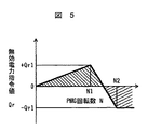
図4は、有効電力指令値PrとPMG回転数Nとの関係の例を示す。有効電力指令値Prは、定格をPr1とすると、回転数に応じてハッチングした範囲を取ることができる。無効電力指令値Qrは、前記の無効電力指令値ゲインKqと有効電力指令値Prとから次式で表される。
【0024】
【数4】
Qr=Qo+Kq・Pr
図5は、無効電力指令値QrとPMG回転数Nとの関係の例を示す。無効電力指令値Qrは、有効電力指令値PrとPMG回転数Nから決まる無効電力指令値ゲインKqに基づいて図5のハッチングの範囲を取ることができ、無効電力制御回路102の指令値となる。±Qr1は、例えば、±Kq1=±1.0 ,Pr1=1.0PUとすると、+(進み)1.0PU,−(遅れ)1.0PU となる。なお、無効電力指令初期値Qoは、ここでは零に設定しているが、動力源1や永久磁石式発電機2などの条件に合わせて無効電力指令値ゲインKq同様、任意に設定できる。無効電力指令値設定回路104は、図3の特性と(数5)式とを用いて、無効電力指令値Qrを決定する。
【0025】
図6は、電圧指令値ゲインKvとPMG回転数Nとの関係の一例を示す。前記の回転数N1までは、電圧指令値ゲインKvをKv1まで増加させる。回転数N1以降は、電圧指令値ゲインKvの値をKv1一定とし、回転数Nに応じて電圧指令値ゲインKvを決定する。また、電圧指令値Vrは、電圧指令値ゲインKvと前記の有効電力指令値Prから次式で表される。
【0026】
【数5】
Vr=Vo+Kv・Pr
次に、本実施例の制御方法について、図8,図9のベクトル図、及び図10を用いて説明する。図8は、低速回転領域における制御方法を示すベクトル図である。
【0027】
即ち、前記のPMG回転数零からN1までの回転領域である。図8中、Eoは発電機内部誘起電圧、Xは発電機漏れリアクタンス、Iは発電機出力電流、Vtは発電機端子電圧を表す。発電機内部誘起電圧Eoは、回転数に比例して高くなるため、第1の変換器3は、制御装置100によって、発電機出力電流Iと発電機内部誘起電圧Eoが一致するように無効電力指令値Qr、或いは電圧指令値Vrを決定し、発電機端子電圧Vtを制御する。これにより、発電機の力率が改善され、低速回転領域における発電装置の高効率化を図ることができる。
【0028】
図9は、高速回転領域における制御方法を示すベクトル図である。
【0029】
即ち、前記のPMG回転数N1以降の回転領域である。発電機端子電圧Vtは、前述したように回転数N1において既に定格に達しているため、このまま回転数が上がると、過電圧となって発電装置自体が停止してしまう。このため、第1の変換器3は、制御装置100によって、発電機出力電流Iが発電機内部誘起電圧Eoより遅れるように無効電力指令値Qr、或いは電圧指令値Vrを決定し、発電機端子電圧Vtを制御する。これにより、高速回転領域における発電機の可変速範囲を広げることができる。
【0030】
図10にPMG端子電圧VtとPMG回転数Nの関係を示す。C1は、前記の無効電力制御、または電圧制御を行わない場合で、C2は、本発明によるものである。低速回転領域、即ち、回転数零からN1までは、前記図8のベクトル図の関係を満たすために電圧がC1より高めに制御される。また、高速回転領域、即ち、N1からN2までは、例えば、端子電圧を定格Vt1に保つことにより発電機の可変速範囲が広がり、N2以降は、変換器の出力できる無効電力が最大となるために電圧が再び上昇する。
【0031】
(実施例2)
本実施例では、図2の無効電力制御回路102を電圧制御回路、無効電力指令値設定回路104を電圧指令値設定回路とし、電圧指令値設定回路で有効電力指令値PrとPMG回転数Nに基づいて電圧指令値Vrを決定し、電圧制御回路102でPMG端子電圧Vtが指令値Vrとなるように制御し、PMG端子電圧Vtを、(数6)式で求めること以外は実施例1と同じである。
【0032】
【数6】
Vt=SQRT(Vtα2+Vtβ2)
なお、電圧制御回路には、前述と同様にPI(比例積分)型制御などを用いる。
【0033】
図7は、電圧指令値VrとPMG回転数Nとの関係の例を示す。電圧指令値Vrは、有効電力指令値PrとPMG回転数Nから決まる電圧指令値ゲインKvとに基づいて図7のハッチングの範囲で設定され、電圧制御回路の指令値となる。Vr1は、例えば、Kv1=1.0,Pr1=1.0PUとすると、1.0PUとなる。なお、電圧指令初期値Voの設定方法、及び図6の特性と(数6)式の演算式による実現方法については、実施例1の無効電力指令値設定回路104と同様である。
【0034】
また、例えば、ガスタービンなどのように動力源のエネルギーが安定してPMGに伝えられる発電装置の場合には、PMG回転数にほぼ比例した有効電力が得られるため、電圧指令値設定回路の入力として、有効電力指令値Pr、またはPMG回転数Nの何れかでよい。即ち、この場合は、電圧指令値Vrを有効電力指令値Pr、またはPMG回転数Nの何れかに基づいて決定すれば、前述の有効電力指令値PrとPMG回転数Nの両方を用いた場合と同等の効果が得られる。
【0035】
【発明の効果】
本発明によれば、電力変換器の無効電力制御、または電圧制御によって永久磁石式発電機の効率を高め、かつ可変速範囲を広げることができ、変換器容量を有効に活用した高効率でロバストな特性を持つ発電装置を提供できる。
【図面の簡単な説明】
【図1】実施例1の発電装置の構成を示すブロック図である。
【図2】実施例1の第1の変換器の制御装置のブロック図である。
【図3】無効電力指令値ゲインKqとPMG回転数Nとの関係の説明図である。
【図4】有効電力指令値PrとPMG回転数Nとの関係の説明図である。
【図5】無効電力指令値QrとPMG回転数Nとの関係の説明図である。
【図6】電圧指令値ゲインKvとPMG回転数Nとの関係の説明図である。
【図7】電圧指令値VrとPMG回転数Nとの関係の説明図である。
【図8】定常回転領域における制御方法を説明するベクトル図である。
【図9】高回転領域における制御方法を説明するベクトル図である。
【図10】PMG端子電圧VtとPMG回転数Nとの関係の説明図である。
【符号の説明】
1…動力源、2…永久磁石式発電機(PMG)、3…第1の変換器、4…第2の変換器、5…電力系統、21…回転数検出回路、22…電圧検出回路、23…電流検出回路、100…制御装置、101…有効電力制御回路、102…無効電力制御回路、103…変換器制御部、104…無効電力指令値設定回路、200…第2の変換器の制御装置、201…直流電圧制御回路、202…無効電力制御回路、203…変換器制御部。[0001]
BACKGROUND OF THE INVENTION
The present invention relates to a power generator using a permanent magnet generator, and more particularly to control of a power converter.
[0002]
[Prior art]
A power generation apparatus using a target permanent magnet generator rotates a permanent magnet generator using a gas turbine, hydraulic power, wave power, or the like as a power source, and the AC power generated from the permanent magnet generator is first. The converter converts the DC power into DC power, and the DC power transmitted from the first converter is converted again to AC power by the second converter, and the power is supplied.
[0003]
As a method for controlling a power generator using a permanent magnet generator, JP 2000-
Japanese Patent No. 345952 “Wind Wind Multipole Generator and Wind Power Generation Method” describes a method of determining an active power command value based on the rotational speed of a multipole generator and controlling the output power of a variable speed inverter. Japanese Patent Application Laid-Open No. 5-22938, “Control Circuit for Power Conversion System”, describes a method for controlling the power converter so that the terminal voltage of the permanent magnet generator is constant.
[0004]
[Problems to be solved by the invention]
In a power generation device using a permanent magnet generator, it is desirable to have a highly efficient and robust characteristic in order to effectively use energy obtained from a power source.
[0005]
In the prior art, since the active power command value is determined based on the number of revolutions of the generator and the active power control is performed, there is no means for adjusting the power factor of the generator, and the efficiency is considered as a power generation system. It is not always driving. In addition, when the terminal voltage is made constant, a large reactive current flows to increase the terminal voltage, particularly in the region where the generator speed is low, and the potential difference between the induced voltage inside the generator and the terminal voltage increases. The phase difference between the terminal voltage and the current opens, resulting in a decrease in power generation efficiency.
[0006]
An object of the present invention relates to a power generator having a permanent magnet generator, and is highly efficient and robust with respect to a wide variable speed range within a converter capacity by reactive power control or voltage control of a first converter. An object of the present invention is to provide a power generation apparatus having characteristics or a power generation system using the power generation apparatus.
[0007]
[Means for Solving the Problems]
A power generator using a permanent magnet generator according to the present invention includes a permanent magnet generator for generating AC power and a first conversion for converting AC power generated from the generator into DC power. And a second converter for converting DC power transmitted from the first converter into AC power. The first converter has a means for controlling active power and reactive power. The means for controlling and the second converter are provided with means for outputting the first active power.
[0008]
In the power generator using the permanent magnet generator according to the present invention, the first converter includes means for obtaining a reactive power command value from the active power command value and the rotational speed of the generator, and the first converter The reactive power is controlled based on the active power command value and the rotational speed of the generator.
[0009]
In the power generator using the permanent magnet generator according to the present invention, the first converter has a means for controlling active power, a means for controlling voltage, a voltage command based on the active power command value and the rotation speed of the generator. Means for obtaining a value are provided, and the first converter controls the terminal voltage of the generator based on the active power command value and the rotational speed of the generator.
[0010]
A method for setting a power generator using a permanent magnet generator according to the present invention includes means for obtaining a reactive power command value from an active power command value and the rotational speed of the generator, from an active power command value and the rotational speed of the generator. A setting method of a means for obtaining a voltage command value, wherein the reactive power command value or the voltage command value is changed according to the active power command value until the number of revolutions at which the terminal voltage of the generator reaches a rating. Is set so that the phase difference between the internal induced voltage and the generator is zero, and the terminal voltage is constant according to the reactive power command value or the reactive power command value in the region where the rotational speed becomes higher. Set as follows.
[0013]
As described above, it is possible to provide a power generation apparatus having a permanent magnet generator having a highly efficient and robust characteristic that effectively utilizes the converter capacity.
[0014]
DETAILED DESCRIPTION OF THE INVENTION
Embodiments of the present invention will be described below with reference to the drawings.
[0015]
(Example 1)
The configuration of the power generation device of this embodiment will be described with reference to FIG. The power generator using the permanent magnet generator (Permanent-Magnet Generator, hereinafter abbreviated as PMG) of this embodiment uses a
[0016]
In the
[0017]
The
[0018]
[Expression 1]
[Expression 2]
[Equation 3]
The active
[0022]
Next, a setting method of the reactive power command
[0023]
FIG. 4 shows an example of the relationship between the active power command value Pr and the PMG rotation speed N. The active power command value Pr can take a hatched range according to the number of revolutions, when the rating is Pr1. The reactive power command value Qr is expressed by the following equation from the reactive power command value gain Kq and the active power command value Pr.
[0024]
[Expression 4]
Qr = Qo + Kq · Pr
FIG. 5 shows an example of the relationship between the reactive power command value Qr and the PMG rotational speed N. The reactive power command value Qr can take the hatched range of FIG. 5 based on the reactive power command value gain Kq determined from the active power command value Pr and the PMG rotation speed N, and becomes the command value of the reactive
[0025]
FIG. 6 shows an example of the relationship between the voltage command value gain Kv and the PMG rotation speed N. Until the rotation speed N1, the voltage command value gain Kv is increased to Kv1. After the rotation speed N1, the value of the voltage command value gain Kv is kept constant at Kv1, and the voltage command value gain Kv is determined according to the rotation speed N. The voltage command value Vr is expressed by the following equation from the voltage command value gain Kv and the active power command value Pr.
[0026]
[Equation 5]
Vr = Vo + Kv · Pr
Next, the control method of the present embodiment will be described with reference to the vector diagrams of FIGS. 8 and 9 and FIG. FIG. 8 is a vector diagram showing a control method in the low speed rotation region.
[0027]
That is, this is the rotation region from the above-mentioned PMG rotation speed from zero to N1. In FIG. 8, Eo represents the generator internal induced voltage, X represents the generator leakage reactance, I represents the generator output current, and Vt represents the generator terminal voltage. Since the generator internal induced voltage Eo increases in proportion to the rotational speed, the
[0028]
FIG. 9 is a vector diagram showing a control method in the high-speed rotation region.
[0029]
That is, it is a rotation region after the PMG rotation speed N1. Since the generator terminal voltage Vt has already reached the rated value at the rotation speed N1 as described above, if the rotation speed increases as it is, the generator device itself stops due to overvoltage. For this reason, the
[0030]
FIG. 10 shows the relationship between the PMG terminal voltage Vt and the PMG rotational speed N. C1 is the case where the reactive power control or voltage control is not performed, and C2 is according to the present invention. In the low-speed rotation region, that is, from the rotation speed of zero to N1, the voltage is controlled to be higher than C1 in order to satisfy the relationship of the vector diagram of FIG. Further, in the high-speed rotation region, that is, from N1 to N2, for example, the variable speed range of the generator is widened by maintaining the terminal voltage at the rated Vt1, and the reactive power that can be output from the converter is maximized after N2. The voltage rises again.
[0031]
(Example 2)
In this embodiment, the reactive
[0032]
[Formula 6]
Vt = SQRT (Vtα 2 + Vtβ 2 )
The voltage control circuit uses PI (proportional integral) control or the like as described above.
[0033]
FIG. 7 shows an example of the relationship between the voltage command value Vr and the PMG rotation speed N. The voltage command value Vr is set in the hatched range of FIG. 7 based on the active power command value Pr and the voltage command value gain Kv determined from the PMG rotation speed N, and becomes the command value of the voltage control circuit. For example, Vr1 is 1.0 PU when Kv1 = 1.0 and Pr1 = 1.0PU. Note that the method for setting the voltage command initial value Vo and the method for realizing the characteristics shown in FIG. 6 and the formula (Equation 6) are the same as those in the reactive power command
[0034]
In addition, for example, in the case of a power generation device in which the energy of the power source is stably transmitted to the PMG, such as a gas turbine, an effective power almost proportional to the PMG rotation speed can be obtained, so the input of the voltage command value setting circuit As such, either the active power command value Pr or the PMG rotation speed N may be used. That is, in this case, if the voltage command value Vr is determined based on either the active power command value Pr or the PMG rotation speed N, both the above-described active power command value Pr and PMG rotation speed N are used. Equivalent effect is obtained.
[0035]
【The invention's effect】
According to the present invention, the efficiency of the permanent magnet generator can be increased by the reactive power control or voltage control of the power converter, and the variable speed range can be expanded, and the converter capacity is effectively utilized and is robust with high efficiency. It is possible to provide a power generation device having special characteristics.
[Brief description of the drawings]
FIG. 1 is a block diagram illustrating a configuration of a power generator according to a first embodiment.
FIG. 2 is a block diagram of a control device of the first converter according to the first embodiment.
FIG. 3 is an explanatory diagram of a relationship between a reactive power command value gain Kq and a PMG rotation speed N;
4 is an explanatory diagram of a relationship between an active power command value Pr and a PMG rotation speed N. FIG.
FIG. 5 is an explanatory diagram of a relationship between a reactive power command value Qr and a PMG rotational speed N.
6 is an explanatory diagram of a relationship between a voltage command value gain Kv and a PMG rotation speed N. FIG.
7 is an explanatory diagram of a relationship between a voltage command value Vr and a PMG rotational speed N. FIG.
FIG. 8 is a vector diagram illustrating a control method in a steady rotation region.
FIG. 9 is a vector diagram illustrating a control method in a high rotation region.
10 is an explanatory diagram of a relationship between a PMG terminal voltage Vt and a PMG rotation speed N. FIG.
[Explanation of symbols]
DESCRIPTION OF
Claims (5)
前記第1の変換器が有効電力を制御する手段と無効電力を制御する手段とを備え、前記第2の変換器が前記直流系統の電圧を制御する手段を備えることを特徴とする発電装置。A permanent magnet generator for generating AC power, a first converter for converting AC power generated from the generator into DC power of a DC system, and DC power transmitted from the first converter In the power generation apparatus provided with the second converter for converting into AC power,
The power generator according to claim 1, wherein the first converter includes means for controlling active power and means for controlling reactive power, and the second converter includes means for controlling the voltage of the DC system .
前記第1の変換器が有効電力を制御する手段と電圧を制御する手段と、
有効電力指令値と該発電機の回転数から電圧指令値を求める手段を備え、
前記第2の変換器が前記直流系統の電圧を制御する手段を備え、
前記第1の変換器が有効電力指令値と該発電機の回転数に基づいて該発電機の端子電圧を制御することを特徴とする発電装置。A permanent magnet generator for generating AC power, a first converter for converting AC power generated from the generator into DC power, and DC power transmitted from the first converter as AC power In the power generation device including the second converter to convert,
Means for controlling the active power and voltage by the first converter;
Means for obtaining a voltage command value from the active power command value and the rotational speed of the generator;
The second converter comprises means for controlling the voltage of the DC system;
The first converter controls the terminal voltage of the generator based on an active power command value and the rotation speed of the generator.
Priority Applications (4)
| Application Number | Priority Date | Filing Date | Title |
|---|---|---|---|
| JP2001197652A JP4003414B2 (en) | 2001-06-29 | 2001-06-29 | Power generator using permanent magnet generator |
| US10/100,161 US6611437B2 (en) | 2001-06-29 | 2002-03-19 | Power generation apparatus using permanent-magnet generator |
| US10/192,316 US6611438B2 (en) | 2001-06-29 | 2002-07-11 | Power generation apparatus using permanent-magnet generator |
| US10/417,145 US6731522B2 (en) | 2001-06-29 | 2003-04-17 | Power generation apparatus using permanent-magnet generator |
Applications Claiming Priority (1)
| Application Number | Priority Date | Filing Date | Title |
|---|---|---|---|
| JP2001197652A JP4003414B2 (en) | 2001-06-29 | 2001-06-29 | Power generator using permanent magnet generator |
Publications (2)
| Publication Number | Publication Date |
|---|---|
| JP2003018897A JP2003018897A (en) | 2003-01-17 |
| JP4003414B2 true JP4003414B2 (en) | 2007-11-07 |
Family
ID=19035218
Family Applications (1)
| Application Number | Title | Priority Date | Filing Date |
|---|---|---|---|
| JP2001197652A Expired - Lifetime JP4003414B2 (en) | 2001-06-29 | 2001-06-29 | Power generator using permanent magnet generator |
Country Status (2)
| Country | Link |
|---|---|
| US (3) | US6611437B2 (en) |
| JP (1) | JP4003414B2 (en) |
Cited By (1)
| Publication number | Priority date | Publication date | Assignee | Title |
|---|---|---|---|---|
| US10511242B2 (en) | 2014-07-28 | 2019-12-17 | Meidensha Corporation | Method for autonomous operation of electricity-generating device |
Families Citing this family (37)
| Publication number | Priority date | Publication date | Assignee | Title |
|---|---|---|---|---|
| US6741482B2 (en) * | 2001-09-14 | 2004-05-25 | Kabushiki Kaisha Toshiba | Power conversion device |
| JP3840416B2 (en) * | 2002-02-18 | 2006-11-01 | 川崎重工業株式会社 | Turbine generator |
| JP4587655B2 (en) * | 2003-10-02 | 2010-11-24 | 東洋電機製造株式会社 | Power generator for distributed power supply |
| US7002317B2 (en) * | 2004-02-18 | 2006-02-21 | Honeywell International Inc. | Matched reactance machine power-generation system |
| JP3918837B2 (en) | 2004-08-06 | 2007-05-23 | 株式会社日立製作所 | Wind power generator |
| DE502004008691D1 (en) * | 2004-08-27 | 2009-01-29 | Woodward Seg Gmbh & Co Kg | Power control for induction machines |
| US7429855B2 (en) * | 2004-09-20 | 2008-09-30 | Hamilton Sundstrand Corporation | Regenerative load bank with a motor drive |
| ITVE20040052A1 (en) * | 2004-12-23 | 2005-03-23 | Idm Srl | CONTINUOUS AND / OR ALTERNATE CURRENT GENERATOR WITH PERMANENT MAGNETS. |
| US7224147B2 (en) * | 2005-07-20 | 2007-05-29 | Hamilton Sundstrand Corporation | Buck/boost method of voltage regulation for a permanent magnet generator (PMG) |
| US7642666B2 (en) * | 2006-11-02 | 2010-01-05 | Hitachi, Ltd. | Wind power generation apparatus, wind power generation system and power system control apparatus |
| AR064292A1 (en) * | 2006-12-12 | 2009-03-25 | Commw Scient Ind Res Org | ENHANCED ENERGY STORAGE DEVICE |
| JP4901881B2 (en) * | 2007-01-26 | 2012-03-21 | 株式会社日立製作所 | Steam turbine power generation facility and operation method thereof |
| US8044527B2 (en) * | 2007-09-26 | 2011-10-25 | General Electric Company | Electric power generation with magnetically geared machine |
| DE102008034531A1 (en) * | 2008-02-20 | 2009-08-27 | Repower Systems Ag | Wind energy plant with doubly fed asynchronous generator and inverter control |
| US7952331B2 (en) * | 2008-06-20 | 2011-05-31 | Honeywell International Inc. | Self-excited controlled frequency generator system with bi-directional converter |
| WO2010049976A1 (en) * | 2008-10-31 | 2010-05-06 | 三菱電機株式会社 | Power converter |
| JP4831843B2 (en) * | 2009-01-07 | 2011-12-07 | 三菱重工業株式会社 | Wind power generator and output control method thereof |
| JP4894906B2 (en) * | 2009-11-13 | 2012-03-14 | 株式会社日立製作所 | Wind power generation system control method |
| JP5320311B2 (en) * | 2010-01-18 | 2013-10-23 | 三菱重工業株式会社 | Variable speed generator and control method thereof |
| EP2621071A4 (en) * | 2010-09-22 | 2017-05-17 | Toshiba Mitsubishi-Electric Industrial Systems Corporation | Power conversion device |
| US8569994B2 (en) * | 2011-03-15 | 2013-10-29 | General Electric Company | Charging device, system, and method of supplying power to at least one load |
| GB2493711B (en) | 2011-08-12 | 2018-04-25 | Openhydro Ip Ltd | Method and system for controlling hydroelectric turbines |
| FR2984039B1 (en) * | 2011-12-08 | 2015-01-16 | Valeo Equip Electr Moteur | METHOD AND SYSTEM FOR CONTROLLING A MOTOR VEHICLE ALTERNATOR, AND ALTERNATOR OF A MOTOR VEHICLE COMPRISING SUCH A SYSTEM |
| WO2013108288A1 (en) * | 2012-01-18 | 2013-07-25 | 株式会社 日立製作所 | Wind power generating system |
| CN102946110B (en) * | 2012-10-26 | 2014-06-04 | 河南师范大学 | Fixed frequency model prediction control method for voltage type PWM (Pulse Width Modulation) rectifier in process of voltage unbalance drop |
| EP2741392A3 (en) * | 2012-12-04 | 2016-12-14 | ABB Research Ltd. | Systems and methods for utilizing an active compensator to augment a diode rectifier |
| CN103475009B (en) * | 2013-08-02 | 2016-08-17 | 李啸骢 | A kind of Multi-index nonlinear control method for direct-drive permanent-magnetism wind turbine current transformer |
| CN103490435B (en) * | 2013-09-30 | 2015-08-05 | 西南交通大学 | A kind of method utilizing permanent-magnet synchronous blower fan rotation function to improve power system damping |
| FR3013528B1 (en) * | 2013-11-19 | 2016-01-01 | Valeo Equip Electr Moteur | INTEGRATED PORTIONAL CONTROL RING FOR A DIGITAL REGULATOR DEVICE OF A ROTATING ELECTRIC MACHINE WITH EXCITATION OF A MOTOR VEHICLE |
| CN103795081B (en) * | 2014-01-27 | 2016-06-01 | 太原科技大学 | The control method of direct-driving type wind power system low voltage crossing |
| WO2015134493A1 (en) * | 2014-03-03 | 2015-09-11 | AVI-On Labs, LLC | Networking systems, protocols, and methods for controlling target devices |
| JP2016019297A (en) * | 2014-07-04 | 2016-02-01 | 株式会社安川電機 | Series multiple matrix converter, power generation system, and power factor control method |
| CN105790298B (en) * | 2014-12-23 | 2019-03-12 | 台达电子工业股份有限公司 | wind power generation control device and wind power generation system |
| CN104579059A (en) * | 2015-01-12 | 2015-04-29 | 华侨大学 | Rare earth permanent magnet generator voltage regulator |
| CN105932688B (en) * | 2016-03-18 | 2018-09-14 | 国电南瑞科技股份有限公司 | A kind of active power regulation and control method of smooth impact industrial electrical load |
| CN105978011B (en) * | 2016-04-20 | 2018-08-21 | 华北电力大学 | Flexible subregion interconnect device steady-state model for dispatching of power netwoks |
| CN118040783B (en) * | 2024-02-05 | 2024-09-27 | 中国电力科学研究院有限公司 | Variable speed phase regulator control method and device |
Family Cites Families (16)
| Publication number | Priority date | Publication date | Assignee | Title |
|---|---|---|---|---|
| CH652392A5 (en) * | 1982-02-10 | 1985-11-15 | Ciba Geigy Ag | METHOD FOR PRODUCING INDOLES SUBSTITUTED IN THE 2,3 POSITION. |
| DE3706792A1 (en) * | 1987-03-03 | 1988-09-15 | Basf Ag | METHOD FOR PRODUCING 7-CHLORINE-CHINOLINE-8-CARBONIC ACID |
| US4947100A (en) * | 1989-10-16 | 1990-08-07 | Sundstrand Corporation | Power conversion system with stepped waveform inverter having prime mover start capability |
| US4968926A (en) * | 1989-10-25 | 1990-11-06 | Sundstrand Corporation | Power conversion system with stepped waveform DC to AC converter having prime mover start capability |
| US4939441A (en) * | 1989-10-27 | 1990-07-03 | Sundstrand Corporation | Excitation system for a brushless generator having separate AC and DC exciter field windings |
| US5015941A (en) * | 1989-10-30 | 1991-05-14 | Sundstrand Corporation | Power conversion system with bi-directional power converter having prime mover start capability |
| US5038095A (en) * | 1989-12-05 | 1991-08-06 | Sundstrand Corporation | Control for a DC link power conversion system |
| US5008801A (en) * | 1989-12-11 | 1991-04-16 | Sundstrand Corporation | VSCF power conversion system using an output autotransformer |
| US5068590A (en) * | 1989-12-20 | 1991-11-26 | Sundstrand Corporation | Brushless generator having AC excitation in generating and starting modes |
| US5027265A (en) * | 1989-12-20 | 1991-06-25 | Sundstrand Corporation | Regulator for stepped-waveform inverter |
| US5055992A (en) * | 1990-01-29 | 1991-10-08 | Sundstrand Corporation | Control for full-bridge inverter |
| JP2760646B2 (en) * | 1990-09-18 | 1998-06-04 | 株式会社東芝 | Current command value calculation device for power converter |
| JPH0522938A (en) | 1991-01-14 | 1993-01-29 | Advance Koojienereeshiyon Syst Gijutsu Kenkyu Kumiai | Controlling circuit for power conversion system |
| US5587647A (en) * | 1995-06-30 | 1996-12-24 | Sundstrand Corporation | Dual output synchronous-induction starting/generating system |
| JP2000345952A (en) | 1999-06-04 | 2000-12-12 | Mitsubishi Heavy Ind Ltd | Multipolar wind power generator and wind power generating method |
| JP3982232B2 (en) * | 2001-10-25 | 2007-09-26 | 株式会社日立製作所 | Sensorless control device and control method for synchronous generator |
-
2001
- 2001-06-29 JP JP2001197652A patent/JP4003414B2/en not_active Expired - Lifetime
-
2002
- 2002-03-19 US US10/100,161 patent/US6611437B2/en not_active Expired - Fee Related
- 2002-07-11 US US10/192,316 patent/US6611438B2/en not_active Expired - Fee Related
-
2003
- 2003-04-17 US US10/417,145 patent/US6731522B2/en not_active Expired - Fee Related
Cited By (1)
| Publication number | Priority date | Publication date | Assignee | Title |
|---|---|---|---|---|
| US10511242B2 (en) | 2014-07-28 | 2019-12-17 | Meidensha Corporation | Method for autonomous operation of electricity-generating device |
Also Published As
| Publication number | Publication date |
|---|---|
| US6731522B2 (en) | 2004-05-04 |
| US6611437B2 (en) | 2003-08-26 |
| US20030007368A1 (en) | 2003-01-09 |
| JP2003018897A (en) | 2003-01-17 |
| US20030214823A1 (en) | 2003-11-20 |
| US20030007371A1 (en) | 2003-01-09 |
| US6611438B2 (en) | 2003-08-26 |
Similar Documents
| Publication | Publication Date | Title |
|---|---|---|
| JP4003414B2 (en) | Power generator using permanent magnet generator | |
| JP4007268B2 (en) | Wind power generator | |
| US6954004B2 (en) | Doubly fed induction machine | |
| US6984897B2 (en) | Electro-mechanical energy conversion system having a permanent magnet machine with stator, resonant transfer link and energy converter controls | |
| EP2400619B1 (en) | Low cost current source converters for power generation application | |
| Peña et al. | A topology for multiple generation system with doubly fed induction machines and indirect matrix converter | |
| Poddar et al. | Sensorless variable-speed controller for existing fixed-speed wind power generator with unity-power-factor operation | |
| CN106160606A (en) | Wind power generation system and control method thereof | |
| US20190312502A1 (en) | DFIG Converter with Active Filter | |
| CN109639204A (en) | Flywheel energy storage control system and control method based on ten two-phase permanent magnet synchronous motors | |
| US7414331B2 (en) | Power converter system and method | |
| CN113904387A (en) | Systems and methods for reducing voltage distortion from inverter-based resources | |
| JP3073719B2 (en) | Pumped storage generator | |
| Tremblay et al. | Direct power control of a DFIG-based WECS with active filter capabilities | |
| JP3884260B2 (en) | Wind power generator | |
| WO2020013015A1 (en) | Variable-speed generator-motor device | |
| JP2000345952A (en) | Multipolar wind power generator and wind power generating method | |
| Morawiec et al. | Power control structure of doubly-fed induction generator supplied by current source converter | |
| JP2007518384A (en) | 3-phase AC variable speed motor | |
| Koczara et al. | Smart and decoupled power electronic generation system | |
| He | DC Bus Voltage Adaptive Control for DC Microgrid with Wind Power Generator Systems | |
| Nasir | Dynamic Modeling of Wound-Rotor Slip-Ring Induction Generator with Switched-Excitation Capacitance and Chopper Resistance Across Bridge Rectifier in the Rotor Circuit | |
| JP4018262B2 (en) | Frequency converter | |
| Reyes et al. | Control of a doubly-fed induction generator via a direct two-stage power converter | |
| CN108123610B (en) | Conversion circuit for six-phase motor |
Legal Events
| Date | Code | Title | Description |
|---|---|---|---|
| A621 | Written request for application examination |
Free format text: JAPANESE INTERMEDIATE CODE: A621 Effective date: 20040830 |
|
| A977 | Report on retrieval |
Free format text: JAPANESE INTERMEDIATE CODE: A971007 Effective date: 20060209 |
|
| A131 | Notification of reasons for refusal |
Free format text: JAPANESE INTERMEDIATE CODE: A131 Effective date: 20060404 |
|
| RD01 | Notification of change of attorney |
Free format text: JAPANESE INTERMEDIATE CODE: A7421 Effective date: 20060418 |
|
| A521 | Request for written amendment filed |
Free format text: JAPANESE INTERMEDIATE CODE: A523 Effective date: 20060605 |
|
| A131 | Notification of reasons for refusal |
Free format text: JAPANESE INTERMEDIATE CODE: A131 Effective date: 20070227 |
|
| A521 | Request for written amendment filed |
Free format text: JAPANESE INTERMEDIATE CODE: A523 Effective date: 20070427 |
|
| TRDD | Decision of grant or rejection written | ||
| A01 | Written decision to grant a patent or to grant a registration (utility model) |
Free format text: JAPANESE INTERMEDIATE CODE: A01 Effective date: 20070731 |
|
| A61 | First payment of annual fees (during grant procedure) |
Free format text: JAPANESE INTERMEDIATE CODE: A61 Effective date: 20070813 |
|
| R151 | Written notification of patent or utility model registration |
Ref document number: 4003414 Country of ref document: JP Free format text: JAPANESE INTERMEDIATE CODE: R151 |
|
| FPAY | Renewal fee payment (event date is renewal date of database) |
Free format text: PAYMENT UNTIL: 20100831 Year of fee payment: 3 |
|
| FPAY | Renewal fee payment (event date is renewal date of database) |
Free format text: PAYMENT UNTIL: 20100831 Year of fee payment: 3 |
|
| FPAY | Renewal fee payment (event date is renewal date of database) |
Free format text: PAYMENT UNTIL: 20110831 Year of fee payment: 4 |
|
| FPAY | Renewal fee payment (event date is renewal date of database) |
Free format text: PAYMENT UNTIL: 20120831 Year of fee payment: 5 |
|
| FPAY | Renewal fee payment (event date is renewal date of database) |
Free format text: PAYMENT UNTIL: 20120831 Year of fee payment: 5 |
|
| FPAY | Renewal fee payment (event date is renewal date of database) |
Free format text: PAYMENT UNTIL: 20130831 Year of fee payment: 6 |
|
| S111 | Request for change of ownership or part of ownership |
Free format text: JAPANESE INTERMEDIATE CODE: R313111 |
|
| R350 | Written notification of registration of transfer |
Free format text: JAPANESE INTERMEDIATE CODE: R350 |
|
| EXPY | Cancellation because of completion of term |