JP3984900B2 - Spacing member and process cartridge - Google Patents
Spacing member and process cartridge Download PDFInfo
- Publication number
- JP3984900B2 JP3984900B2 JP2002286915A JP2002286915A JP3984900B2 JP 3984900 B2 JP3984900 B2 JP 3984900B2 JP 2002286915 A JP2002286915 A JP 2002286915A JP 2002286915 A JP2002286915 A JP 2002286915A JP 3984900 B2 JP3984900 B2 JP 3984900B2
- Authority
- JP
- Japan
- Prior art keywords
- photosensitive drum
- process cartridge
- shutter member
- charging roller
- image forming
- Prior art date
- Legal status (The legal status is an assumption and is not a legal conclusion. Google has not performed a legal analysis and makes no representation as to the accuracy of the status listed.)
- Expired - Fee Related
Links
- 238000000034 method Methods 0.000 title claims description 117
- 238000000926 separation method Methods 0.000 claims description 69
- 230000001681 protective effect Effects 0.000 claims description 7
- 238000012546 transfer Methods 0.000 description 95
- 239000002699 waste material Substances 0.000 description 16
- 238000004140 cleaning Methods 0.000 description 15
- 230000008878 coupling Effects 0.000 description 13
- 238000010168 coupling process Methods 0.000 description 13
- 238000005859 coupling reaction Methods 0.000 description 13
- 238000003780 insertion Methods 0.000 description 9
- 230000037431 insertion Effects 0.000 description 9
- 239000002184 metal Substances 0.000 description 8
- 230000003014 reinforcing effect Effects 0.000 description 6
- 230000006835 compression Effects 0.000 description 5
- 238000007906 compression Methods 0.000 description 5
- 238000011161 development Methods 0.000 description 5
- 238000003860 storage Methods 0.000 description 5
- 238000009826 distribution Methods 0.000 description 4
- 239000000463 material Substances 0.000 description 4
- 230000007547 defect Effects 0.000 description 3
- 230000006870 function Effects 0.000 description 3
- 230000002265 prevention Effects 0.000 description 3
- 125000006850 spacer group Chemical group 0.000 description 3
- 230000005540 biological transmission Effects 0.000 description 2
- 230000015572 biosynthetic process Effects 0.000 description 2
- 230000000694 effects Effects 0.000 description 2
- 238000000605 extraction Methods 0.000 description 2
- 238000005192 partition Methods 0.000 description 2
- 108091008695 photoreceptors Proteins 0.000 description 2
- 238000003825 pressing Methods 0.000 description 2
- 241001272720 Medialuna californiensis Species 0.000 description 1
- CBENFWSGALASAD-UHFFFAOYSA-N Ozone Chemical compound [O-][O+]=O CBENFWSGALASAD-UHFFFAOYSA-N 0.000 description 1
- 238000013019 agitation Methods 0.000 description 1
- 239000003086 colorant Substances 0.000 description 1
- 230000002950 deficient Effects 0.000 description 1
- 238000001514 detection method Methods 0.000 description 1
- 230000001012 protector Effects 0.000 description 1
- 238000006748 scratching Methods 0.000 description 1
- 230000002393 scratching effect Effects 0.000 description 1
- 238000011144 upstream manufacturing Methods 0.000 description 1
- 238000012800 visualization Methods 0.000 description 1
- 238000003466 welding Methods 0.000 description 1
- 239000002023 wood Substances 0.000 description 1
Images


Classifications
-
- G—PHYSICS
- G03—PHOTOGRAPHY; CINEMATOGRAPHY; ANALOGOUS TECHNIQUES USING WAVES OTHER THAN OPTICAL WAVES; ELECTROGRAPHY; HOLOGRAPHY
- G03G—ELECTROGRAPHY; ELECTROPHOTOGRAPHY; MAGNETOGRAPHY
- G03G15/00—Apparatus for electrographic processes using a charge pattern
- G03G15/01—Apparatus for electrographic processes using a charge pattern for producing multicoloured copies
- G03G15/0142—Structure of complete machines
- G03G15/0178—Structure of complete machines using more than one reusable electrographic recording member, e.g. one for every monocolour image
-
- G—PHYSICS
- G03—PHOTOGRAPHY; CINEMATOGRAPHY; ANALOGOUS TECHNIQUES USING WAVES OTHER THAN OPTICAL WAVES; ELECTROGRAPHY; HOLOGRAPHY
- G03G—ELECTROGRAPHY; ELECTROPHOTOGRAPHY; MAGNETOGRAPHY
- G03G15/00—Apparatus for electrographic processes using a charge pattern
- G03G15/01—Apparatus for electrographic processes using a charge pattern for producing multicoloured copies
- G03G15/0105—Details of unit
- G03G15/0121—Details of unit for developing
-
- G—PHYSICS
- G03—PHOTOGRAPHY; CINEMATOGRAPHY; ANALOGOUS TECHNIQUES USING WAVES OTHER THAN OPTICAL WAVES; ELECTROGRAPHY; HOLOGRAPHY
- G03G—ELECTROGRAPHY; ELECTROPHOTOGRAPHY; MAGNETOGRAPHY
- G03G15/00—Apparatus for electrographic processes using a charge pattern
- G03G15/01—Apparatus for electrographic processes using a charge pattern for producing multicoloured copies
- G03G15/0142—Structure of complete machines
- G03G15/0147—Structure of complete machines using a single reusable electrographic recording member
- G03G15/0152—Structure of complete machines using a single reusable electrographic recording member onto which the monocolour toner images are superposed before common transfer from the recording member
- G03G15/0173—Structure of complete machines using a single reusable electrographic recording member onto which the monocolour toner images are superposed before common transfer from the recording member plural rotations of recording member to produce multicoloured copy, e.g. rotating set of developing units
-
- G—PHYSICS
- G03—PHOTOGRAPHY; CINEMATOGRAPHY; ANALOGOUS TECHNIQUES USING WAVES OTHER THAN OPTICAL WAVES; ELECTROGRAPHY; HOLOGRAPHY
- G03G—ELECTROGRAPHY; ELECTROPHOTOGRAPHY; MAGNETOGRAPHY
- G03G2215/00—Apparatus for electrophotographic processes
- G03G2215/01—Apparatus for electrophotographic processes for producing multicoloured copies
- G03G2215/0103—Plural electrographic recording members
- G03G2215/0109—Single transfer point used by plural recording members
- G03G2215/0116—Rotating set of recording members
Landscapes
- Physics & Mathematics (AREA)
- General Physics & Mathematics (AREA)
- Electrophotography Configuration And Component (AREA)
Description
【0001】
【発明の属する技術分野】
本発明は、プロセスカートリッジに取り付ける離間部材及びこの離間部材を取り付けたプロセスカートリッジ及びプロセスカートリッジを脱着可能な画像形成装置に関する。
【0002】
ここで、画像形成装置とは、例えば、電子写真複写機、電子写真プリンタ(LEDプリンタ、レーザービームプリンタ等)、電子写真ファクシミリ装置及び電子写真ワードプロセッサ等が含まれる。
【0003】
また、プロセスカートリッジとは、電子写真感光体と電子写真感光体に作用するプロセス手段の少なくとも一つとを一体的にカートリッジ化し、このカートリッジを画像形成装置本体に対して着脱可能とするものをいう。
【0004】
【従来の技術】
電子写真画像形成プロセスを用いた画像形成装置においては、像担持体である感光ドラム上に形成した現像剤像を記録媒体に転写して画像を形成し、また、カラー画像形成装置にあっては、感光ドラム上に順次形成する各色の現像剤像を中間転写体に重畳転写し、そのカラー画像を記録媒体に一括転写する構成を有するものが用いられてきた。この場合、感光ドラム等の劣化や消耗する部分の取り扱いを容易にするために、これらをユニット化して画像形成装置本体に着脱可能とするプロセスカートリッジ方式が広く用いられている。
【0005】
中間転写体を用いたカラー画像形成装置の一従来例としては、図10に示す装置(以下、「従来装置A」という)のように、感光体ユニット350と中間転写体ユニット351とがそれぞれ独立したカートリッジとして構成され、大きな可動側フレーム352を装置前面へ回動して開き、感光体ユニット350と中間転写体ユニット351を各々上方より挿入して装置本体に装着するように構成されている。
【0006】
また、中間転写体を用いたカラー画像形成装置の他の従来例としては、特許文献1や特許文献2等に記載されているように、感光体ベルトと中間転写ベルト及び除去現像剤収容ボックスが一体構成となった装置(以下、「従来装置B」という)が提案されている。
【0007】
従来装置Bにおいては、中間転写ベルトの投影下方面に感光体ベルトと除去現像剤収容ボックスを配置した構成となっており、また従来装置Aと同様に、大きな可動側フレームを装置前面へ回動して開き、中間転写体と感光体及び除去現像剤収容ボックスが一体となったプロセスカートリッジを上方より挿入する構成となっている。
【0008】
これら電子写真方式によって画像を形成するプロセスカートリッジの感光ドラム表面に帯電処理を行う方法としては、コロナ帯電装置が広く実用化されている。このコロナ帯電は、被帯電面を所定電位に均一に帯電処理を行う方法として有効である。しかし高圧電源を必要とし、またコロナ放電によるオゾン発生などの問題があるため、他の帯電方法として帯電ローラを感光ドラム表面に接触させて帯電処理を行う接触帯電装置が知られている。
【0009】
接触帯電装置は、感光ドラム表面に確実に接触させて設置する必要があるために所定の押し圧を持って圧接している。
【0010】
従って、その状態で長期間に渡って作動させることなく保存しておくと、帯電ローラは同一個所のみに変形を生じさせている状態となり、その場合ゴムのクリープ現象に伴なう変形が起きてしまう。その結果画像上に水平の帯やムラが生じてしまう場合があった。また、物流時の振動による感光ドラムと帯電ローラの摺擦メモリによる画像ムラが生じてしまう場合があった。
【0011】
このような問題が初期画像から発生するのを防ぐためには、スペーサ部材を帯電ローラの芯金と感光ドラムの間に挟み、帯電ローラを感光ドラムから離間させることにより帯電ローラのゴム表層を変形させない構成(例えば、特許文献3参照)や、ソレノイドを用いて加圧、離間を行う方法(例えば、特許文献4参照)などが開示されている。
【0012】
また、画像形成装置本体にプロセスカートリッジを装着するまでの間に、感光ドラムが外光に曝されると、初期の画像形成時において画像不良が生じる場合もあるため、これを防止するための可動式のシャッターが設けられている構成が知られている。
【0013】
【特許文献1】
特開平11−30944号公報
【特許文献2】
特開平10‐177329号公報
【特許文献3】
特開平2‐39169号公報
【特許文献4】
特開平6‐316349号公報
【0014】
【発明が解決しようとする課題】
しかしながら、上記のような従来技術の場合には、下記のような問題が生じていた。
【0015】
スペーサ部材を帯電ローラの芯金と感光ドラムの間に挟み、帯電ローラを感光ドラムから離間させる構成では、ユーザーがスペーサ部材を取り除かずに画像形成装置に装着してしまう場合があり、そのままでは正常な画像形成動作が行われない。
【0016】
また、ソレノイドを用いて加圧、離間を行う構成では、画像形成装置の構成が複雑となりコストアップの要因となる。
【0017】
さらには、感光ドラムが外光に曝されることを防止するための可動式のシャッターが、プロセスカートリッジを画像形成装置に装着するまでの間に開いた状態になってしまう場合があり、外光に曝されることで不良画像発生の要因となる場合がある。
【0018】
本発明は上記の従来技術の課題を解決するためになされたもので、その目的とするところは、プロセスカートリッジの未使用状態において、感光ドラムと帯電ローラとを離間させた状態を保持すると同時にシャッター部材が開いてしまうことを防止し、かつ、画像形成装置本体にプロセスカートリッジを装着する時には感光ドラム及び帯電ローラの離間解除が確実に行なわれる離間部材及びこれを備えたプロセスカートリッジ及び画像形成装置を提供するものである。
【0019】
【課題を解決するための手段】
上記目的を達成するために本発明に係る離間部材にあっては、
静電潜像を担持する感光ドラムと、前記感光ドラムに接触して帯電する帯電ローラと、前記帯電ローラと異なるプロセス手段が当接する前記感光ドラムの露出部を覆うシャッター部材と、を有するプロセスカートリッジに取り付ける離間部材であって、
前記感光ドラムと前記帯電ローラとの間に取り外し可能に挟持され、所定の間隙を設けて前記感光ドラムと前記帯電ローラとを離間する離間部と、
前記シャッター部材が開いてしまうことを防止するためのストッパー部と、
前記シャッター部材が開いてしまうことを防止するための、画像形成装置への前記プロセスカートリッジの装着に連動して前記シャッター部材を開閉させるアーム部を覆うアーム保護部と、
前記画像形成装置に設けられたガイド部に当接しながら装着位置を決める前記プロセスカートリッジの位置決め部を覆うための保護部と、
を備えたことを特徴とする。
【0020】
このような離間部材を取り付けることで、プロセスカートリッジを使用せず保存している状態で、帯電ローラが感光ドラムに接触した状態で加圧されないように帯電ローラと感光ドラムを離間させると共に、感光ドラムのシャッター部材が開くことを簡便な構成で防止することができる。さらに、ユーザーが離間部材を取り付けたまま画像形成装置に装着できないようにしたため、離間部材の取り忘れを防止し、確実に帯電ローラと感光ドラムの離間が行われる。
【0022】
また、本発明に係るプロセスカートリッジにあっては、
画像形成装置に着脱可能なプロセスカートリッジであって、
静電潜像を担持する感光ドラムと、
前記感光ドラムに接触して帯電する帯電ローラと、
前記帯電ローラと異なるプロセス手段が当接する前記感光ドラムの露出部を覆うシャッター部材と、
所定の間隙を設けて前記感光ドラムと前記帯電ローラとを離間する離間部と、前記シャッター部材が開いてしまうことを防止するためのストッパー部と、前記シャッター部材が開いてしまうことを防止するための、前記画像形成装置への前記プロセスカートリッジの装着に連動して前記シャッター部材を開閉させるアーム部を覆うアーム保護部と、前記画像形成装置に設けられたガイド部に当接しながら装着位置を決める前記プロセスカートリッジの位置決め部を覆うための保護部と、を備える離間部材と、
を有し、
前記プロセスカートリッジが前記画像形成装置に装着されていない場合に、前記離間部を前記感光ドラムと前記帯電ローラとの間に取り外し可能に挟持したことを特徴とする。
【0023】
さらに、本発明に係るプロセスカートリッジにあっては、
画像形成装置に着脱可能なプロセスカートリッジであって、
静電潜像を担持する感光ドラムと、
前記感光ドラムに接触し帯電する帯電ローラと、
前記帯電ローラと異なるプロセス手段が当接する前記感光ドラムの露出部を覆うシャッター部材と、所定の間隙を設けて前記感光ドラムと前記帯電ローラとを離間する離間部と、前記シャッター部材が開いてしまうことを防止するためのストッパー部と、前記シャッター部材が開いてしまうことを防止するための、前記画像形成装置への前記プロセスカートリッジの装着に連動して前記シャッター部材を開閉させるアーム部を覆うアーム保護部と、を備える離間部材と、
を有し、
前記離間部材は、前記シャッター部材の開閉方向に対して略直交する方向に取り外し可能に配置されることを特徴とする。
【0024】
この構成によれば、シャッター部材の開閉方向と離間部材の離間部を取り外す方向とが異なるため、シャッター部材が開く方向に外力が加わった場合に離間部材が抜けることを防止できる。
【0027】
【発明の実施の形態】
以下に図面を参照して、この発明の好適な実施の形態を例示的に詳しく説明する。ただし、この実施の形態に記載されている構成部品の寸法、材質、形状、その相対配置などは、特に特定的な記載がない限りは、この発明の範囲をそれらのみに限定する趣旨のものではない。また、以下の説明で一度説明した部材についての材質、形状などは、特に改めて記載しない限り初めの説明と同様のものである。
【0028】
なお、以下の説明において、「装置前面」とは、転写プロセスから定着プロセスへの記録媒体の搬送上流側の面を指し(図2において右側)、「装置本体及びプロセスカートリッジに関して左右」とは、装置前面から見て左または右である。また「長手方向」とは、記録媒体の表面と平行であり、かつ、記録媒体の搬送方向と交差(略直交)する方向である。
【0029】
(第1の実施の形態)
(画像形成装置の全体構成)
はじめに、本発明に係るプロセスカートリッジを好適に用いることができるカラー画像形成装置の全体構成及び動作について、図2を参照して概略説明する。
【0030】
図2は本発明を実施した画像形成装置の一形態で、現像カートリッジと、感光ドラムを含むプロセスカートリッジと、を画像形成装置本体に装填した電子写真方式のカラーレーザービームプリンタの概略構成を示す縦断面図である。
【0031】
感光ドラム1は中間転写ベルト5aの回転と同期して図2の矢印方向(反時計回り)に回転する。帯電装置2は、感光ドラム1の表面を均一に帯電する。露光手段3は、帯電された感光ドラム1表面を各色画像情報に基づいた画像光、例えばイエロー画像情報に基づいた画像光を照射し、感光ドラム1上にイエロー画像に対応した静電潜像を形成する。
【0032】
現像装置4は、静電潜像が形成されると同時に回転駆動し、イエローの現像器4Yを現像位置に移動する。感光ドラム1上の帯電極性と同極性で、帯電電位と電位差を有する電圧が印加された現像ローラは、感光ドラム1上に形成された静電潜像にイエロートナーを付着させて現像する。
【0033】
感光ドラム1の帯電極性と同極性でほぼ同電位の電圧を現像ローラ4aに印加して静電潜像にイエロートナーを付着させて現像する。
【0034】
その後、中間転写ベルト5aを挟んで感光ドラム1と対向して配置された押えローラ(一次転写ローラ)5jにトナーと逆極性のバイアス電圧を印加することで、感光ドラム1上のイエローのトナー像が中間転写ベルト5a上に一次転写される。
【0035】
上述のようにイエロートナー像の一次転写が終了すると、現像装置4の次の現像器(4M)が回転移動し、感光ドラム1に対向する現像位置に位置決めされる。以上のような静電潜像の形成、現像及び一次転写の各工程を、マゼンタ(M)、シアン(C)、ブラック(Bk)の各色についても順次繰り返して行うことによって、中間転写ベルト5a上に4色のトナー像を重ね合わせる。
【0036】
この間、二次転写ローラ11は、中間転写ベルト5aとは非接触状態の位置にあり、クリーニングユニットとしてのクリーニング帯電ローラ5fも中間転写ベルト5aとは非接触状態の位置にある。
【0037】
二次転写ローラ11は、中間転写ベルト5a上に4色のトナー像が形成された後に、図2に示すように、中間転写ベルト5aに圧接される。さらに、中間転写ベルト5aの回転と同期して、給送手段であるレジストローラ対7近辺の所定の位置で待機していた記録媒体が中間転写ベルト5aと二次転写ローラ11のニップ部に送り出される。
【0038】
なお、レジストローラ対7の直前には、記録媒体の先端を検知してレジストローラ対7の回転駆動力を遮断し、記録媒体を所定の位置で待機させるレジ前センサ14が設けられている。
【0039】
二次転写ローラ11にはトナーと逆極性のバイアス電圧が印加されており、中間転写ベルト5a上のトナー像は、搬送されてきた記録媒体の表面に一括して二次転写される。
【0040】
このようにしてトナー像が二次転写された記録媒体は、搬送ベルトユニット12を経由して定着装置8に搬送され、ここで、複数色のトナー像の定着が行われる。
【0041】
トナー像が定着された記録媒体は、排紙ローラ対13によって排紙ガイド15に沿って搬送され、排出ローラ対9によってカラー画像形成装置A上部の排紙トレー10に排出され、画像形成を完了する。
【0042】
一方、クリーニング帯電ローラ5fは、二次転写後に中間転写ベルト5aに圧接され、中間転写ベルト5a上に残った残留トナーに転写時と逆の電荷を与える。
【0043】
逆の電荷を付与された残留トナーは、感光ドラム1に静電気的に付着し、その後感光ドラム用のクリーニングブレード6により回収される。回収された残留トナーは、廃トナーとして後述する搬送経路をたどり、廃トナーボックス216に回収され蓄積される。
【0044】
(現像カートリッジの構成)
ブラック、マゼンタ、イエロー、シアンの各色のトナーを収納した現像カートリッジは現像ロータリー内の所定位置に固定されている。ロータリーは中心軸を中心に回動しその中心軸の両サイドには円体状のロータリーフランジ(図示せぬ)があってこのフランジに現像カートリッジが固定される。
【0045】
この固定によってロータリーが回転してもロータリーから現像カートリッジは離脱しない。現像カートリッジを本体外に離脱させる場合は図示せぬ把手をもって現像カートリッジを引き出す。現像カートリッジはロータリーの両フランジに例えばねじりコイルばねによって係止されておりユーザーの操作によって離脱、装着が可能である。
【0046】
現像カートリッジ本体は、トナー収納部と現像部とに大別される。トナー収納部には所定色のトナーが充填されており攪拌手段が回転することによってトナーを現像部に必要量搬送する。搬送されたトナーは現像部においてスポンジ状のトナー供給ローラの回転によって現像ローラ表面に供給され、さらに薄板状の現像ブレードと現像ローラとの摩擦により電荷を付与され薄層化される。
【0047】
薄層化された現像ローラ上のトナーは、現像ローラの回転により現像部に搬送され、所定の現像バイアスを印加することにより感光ドラム上に形成された静電潜像をトナー像として可視化する。
【0048】
感光ドラム上の静電潜像の可視化に寄与しなかった残トナー、すなわち、現像ローラ表面の未現像トナーは、再度トナー供給ローラ部で剥ぎ取られ、またこれと同時に新しいトナーが現像ローラ上に供給されて新たな現像動作が連続的に行われる。
【0049】
(感光ドラム、中間転写体一体構成プロセスカートリッジ)
次に、本発明の特徴である、感光体ユニット及び中間転写体ユニット一体構成のプロセスカートリッジの構成について図3を参照して説明する。図3は本実施の形態に係るプロセスカートリッジを装置前面に対して左側面から見た縦断面図である。
【0050】
図3に示すように、プロセスカートリッジ5は、中間転写体ユニット21の投影上方面に感光体ユニット20を配置し、感光体ユニット20の装置前面側から見て左側面には、一体構成で廃トナーボックス部216を配置している。
【0051】
また、中間転写体ユニット21のベルト駆動ローラ240には、中間転写ベルト5a上の残留トナーに転写時と逆電荷を付与するためのクリーニング帯電ローラ部223が設けられ、一体構成となっている。
【0052】
感光体ユニット20には、感光ドラム1が両端を左側軸受102(図4参照)と右側軸受106(図5参照)により保持され、感光体フレーム129に回転自在に取り付けられている。そして右側端部のカップリング124(図5参照)を介して装置本体から所定の回転駆動力が伝達されるようになっている。
【0053】
また、感光ドラム1には、図3に示すように、帯電ローラ2が両端の軸受125を介して、圧縮ばね126により所定の力で圧接され、従動回転するようになっている。軸受125の少なくとも片方は導電性の部材で構成され、帯電ローラ2に所定の帯電バイアスを印加することにより、感光ドラム1表面を一様に帯電させるようになっている。なお、このような接触帯電方式の帯電装置に関しては、特開昭63−149669号公報に開示されている。
【0054】
さらに、感光ドラム1にはクリーニングブレード6が所定の位置に設けられている。前記クリーニングブレード6は、感光ドラム1上のトナー像を中間転写ベルト5a上に1次転写した後、感光ドラム1上に残った残留トナーを掻き取るように構成されている。また、前述の逆電荷を付与された中間転写ベルト5a上の残留トナー(2次転写後に中間転写ベルト5a上に残った残留トナー)も感光ドラム1上に回収し、1次転写後の感光ドラム1上の残留トナーと共に掻き取るように構成されている。
【0055】
掻き取られた廃トナーはスクイシート127により中間転写ベルト5a上への落下が阻止される。感光体フレーム129の底部に溜まった廃トナーは搬送スクリュー128の回転により、装置前面から見て左側へ搬送されていく。
【0056】
その後廃トナーは搬送スクリュー128により感光体ユニット20の左側側面(装置前面から見て)に搬送され、中間転写ベルト5aを中心として感光体ユニット20の反対側に設けられた廃トナーボックス216に滑り落ち蓄積されていく。
【0057】
廃トナーボックス216は、中間転写体フレーム245の一部に仕切り板250を溶着して形成されていて、感光ドラム1上の残留トナーは最終的にこの廃トナーボックス216に収納される。
【0058】
中間転写体フレーム245の左側面には羽根車カバー253がシール部材を挟んで結合している。羽根車カバー253は、上側に開口253aがあり、感光体フレーム129の左端下部に設けられた開口152とシール部材254を挟んで接合しており、開口152から落下した廃トナーが羽根車カバー253内部に落下する。
【0059】
羽根車カバー253内部には羽根車255が左側面から見て反時計周りに回転し、内部の廃トナーを廃トナーボックス216の方へ搬送している。羽根車カバー253は、廃トナーボックス216の左側面にオーバーラップしており、オーバーラップした部分に、羽根車カバー253内部に通じている穴が設けられている。
【0060】
さらに、前記穴から長手方向に伸びた位置に、第二スクリュー258が設けられていて、羽根車255によって搬送された廃トナーが、第二スクリュー258を回転することで廃トナーボックス左側から右側奥へと搬送されていく。
【0061】
廃トナーボックス216には第二スクリュー258と垂直な複数の隔壁によって、いくつかの小部屋に仕切られており、左端の小部屋から右隣の小部屋へと順次満たされていく。そして一番右側の小部屋には、図示しない廃トナーボックス216の満タンを検知する検知部が設けられている。
【0062】
また、感光体ユニット20には画像形成装置本体に着脱する動作に連動して開閉するシャッター部材119も設けられている。
【0063】
(中間転写体ユニット21の構成)
次に、中間転写体ユニット21の構成について説明する。
【0064】
中間転写ベルト5aは、握手部280を含む中間転写体フレーム245に保持される駆動ローラ240と従動ローラ241との2本のローラにより懸回張設されている。
【0065】
駆動ローラ240は両端を左側軸受201(図4参照)と右側軸受205(図5参照)とにより回転自在に保持され、右側端部のカップリング242(図5参照)を介して装置本体から所定の回転駆動力が伝達されるようになっている。また、従動ローラ241の両端の軸受243には圧縮ばね244が設けられ、中間転写ベルト5aに所定の張力を与えるようになっている。
【0066】
中間転写ベルト5aを挟んで、感光ドラム1と対向する位置には、一次転写ローラ5jが設けられている。この一次転写ローラ5jは、両端の軸受246を介して、圧縮ばね247により所定の力で中間転写ベルト5aを介して感光ドラム1に圧接され、従動回転するようになっている。
【0067】
軸受246の少なくとも片方は導電性の部材で構成され、一次転写ローラ5jに所定の帯電バイアス電圧を印加することにより、感光ドラム1表面上のトナーは中間転写ベルト5a上に一次転写される。
【0068】
また、中間転写ベルトの駆動ローラ240に対向する位置には、中間転写ベルト5a上の残留トナーに転写時と逆電荷を付与するためのクリーニング帯電ローラ部223が設けられている。
【0069】
クリーニング帯電ローラ5fは、両端の軸受211を介して、圧縮ばね212により所定の力で中間転写ベルト5aを介して駆動ローラ240に圧接され、従動回転するようになっている。
【0070】
また、軸受211の少なくとも片方は導電性の部材で構成され、クリーニング帯電ローラ5fに転写時と逆の電圧を印加することにより、中間転写ベルト5a上の残留トナーに転写時と逆の電荷を付与し、感光ドラム1でドラム表面に静電気的に吸着回収され、前述したように廃トナーボックス216に蓄積される。
【0071】
(プロセスカートリッジのユニット構成)
次に本発明に係るプロセスカートリッジ5のユニット構成について、図4乃至図8を用いて詳細に説明する。図4は本実施の形態に係るプロセスカートリッジを左側から見た斜視図であり、図5は同じく右側から見た斜視図であり、図6は本実施の形態に係るプロセスカートリッジの構成を説明するために左側から見た分解斜視図であり、図7は同じく右側から見た分解斜視図であり、図8は本実施の形態に係るプロセスカートリッジを装置本体に装着した際に右側面方向から見た概略断面図である。
【0072】
フレーム構成は大きく2つに分割される。まず、第一ユニットである感光体ユニット20は、感光体フレーム129、感光ドラム1、右側軸受106、左側軸受102、帯電ローラ2、クリーニングブレード6、搬送スクリュー128、シャッター部材119を主要部品として構成される。
【0073】
感光体ユニット20を構成する感光体フレーム129は、そのフレーム側面129aに複数の係合部を有している。フレーム側面129aの後方には、後述する金属ピン140、141によって揺動自在に支持されるための穴129bが設けられている。
【0074】
この穴129bは、図8に示すように感光ドラム1中心に向かう方向に長穴形状となっている。またフレーム側面129aの前方には、感光ドラム1を回転自在に保持する右側軸受106、左側軸受102がそれぞれ位置決め固定されている。
【0075】
また、感光体フレーム129のフレーム側面129aは図8に示すように、感光ドラム周方向の中間転写ベルト5a当接部X及び現像ローラ当接部Yとの間が補強連結部130により一体的に連結されており、さらにその補強連結部130の両端部には、後述する中間転写体ユニット21へ組み込む際の抜け止めとして機能する抜け止め軸130a、130bが一体的に形成されている。
【0076】
第二ユニットである中間転写体ユニット21は、中間転写体フレーム245に中間転写ベルト5aを駆動ローラ240と従動ローラ241とにより懸回張設され、かつ感光ドラム1と対向する中間転写ベルト5a内側には一次転写ローラ5j、駆動ローラ240にはクリーニング帯電ローラ5fも配置した構成である。
【0077】
中間転写体フレーム245の両側には、右サイドカバー261、左サイドカバー260がビス止め等の手段により固定されている。右サイドカバー261の外側面からは、駆動ローラ240の右側軸受205のフランジ部と右サイドカバー261と一体的に設けられた突起部204とが突出している。また、左サイドカバー260の外側面からは、右サイドカバー261と同様、駆動ローラ240の左側軸受201のフランジ部と左サイドカバー260と一体的に設けられた突起部203が突出している。
【0078】
次に上記第一ユニット(感光体ユニット20)及び第二ユニット(中間転写体ユニット21)を一体化することにより構成されるプロセスカートリッジ5の組付けについて説明する。
【0079】
プロセスカートリッジ5は、前述したようにまず感光ドラム1が回転自在に支持された感光体ユニット20と、感光ドラム1上に形成されたトナー画像が転写される中間転写ベルト5aを有する中間転写体ユニット21とにそれぞれ別途組付けられた状態になっている。
【0080】
ここで中間転写体ユニット21の左右サイドカバー260、261及び中間転写体フレーム245には、図6、図7に示すように、同軸上に金属ピン140、141を圧入支持するための穴260a、261a及び245a、245bがそれぞれ設けられており、また、クリーニング帯電ローラ部223のフレーム224両端部には、上記感光体ユニット20を組付けた際の抜け止め用の穴223a、223bがそれぞれ設けられている。
【0081】
感光体ユニット20の中間転写体ユニット21への組付けは、まず中間転写体ユニット21の抜け止め用の穴223a、223bに感光体フレーム129の補強連結部130に設けた抜け止め軸130a、130bを挿入する。
【0082】
次に、フレーム側面129aの穴129bと左右サイドカバー260、261及び中間転写体フレーム245の穴260a、245a及び261a、245bとの軸線を合わせた状態で金属ピン140、141を圧入する。
【0083】
この際、中間転写体ユニット21の抜け止め用の穴223a、223bと感光体フレーム129補強連結部130の抜け止め軸130a、130bとは所定の隙間を有して嵌合している。
【0084】
また、感光ドラム1を回転自在に保持し、感光体フレーム129に係合して位置決め固定された右側軸受106と左側軸受102が、右サイドカバー261及び左サイドカバー260にそれぞれ設けられたU溝261b、260bを介して外方に突出している。
【0085】
この右側軸受106及び左側軸受102とU溝261b及び260bも、それぞれが所定の隙間を有するよう構成されている。従って感光体ユニット20は中間転写体ユニット21に対して金属ピン140、141により揺動可能となるように支持され、かつフレーム側面129aの穴129bを長穴形状で構成していることにより、感光体ユニット20と中間転写体ユニット21はその相対位置が移動可能な状態になっている。
【0086】
上記プロセスカートリッジ5を画像形成装置Aに装着する際、感光体ユニット20は右サイドカバー261及び左サイドカバー260より突出した右側軸受106と左側軸受102が装置本体に直接位置決めされ、感光ドラム1が固定される。
【0087】
また、中間転写体ユニット21は駆動ローラ240の右側軸受205フランジ部と右サイドカバー261の突起部204、及び駆動ローラ240の左側軸受201フランジ部と左サイドカバー260の突起部203が装置本体に直接位置決めされる。
【0088】
ここで、感光体ユニット20と中間転写体ユニット21は一体化されたカートリッジの状態となっているため、感光体ユニット20及び中間転写体ユニット21の駆動伝達カップリングは部品公差等により相対的な位置ずれが生じることになるが、感光体ユニット20は中間転写体ユニット21に対し揺動可能に支持され、かつ相対的に移動可能な状態となっているため、感光体ユニット20及び中間転写体ユニット21の駆動伝達カップリングを各々独立して装置本体に位置決めしても、その部品公差等による相対的な位置ずれは吸収される。
【0089】
また同時に、感光体ユニット20の感光体フレーム129の両方のフレーム側面129aを補強連結部130によって一体的に連結補強し、かつその補強連結部130に感光体ユニット20の抜け止め機能を設け、さらに感光体ユニット20を左右サイドカバー260、261及び中間転写体フレーム245に圧入した両持ちの金属ピン140、141によって中間転写体ユニット21に対して揺動可能に支持するよう構成した。
【0090】
これにより、感光体ユニット20は感光ドラム1の支持剛性及び中間転写体ユニット21に対する感光体ユニット20の結合剛性が高く、かつ組付けが簡単なプロセスカートリッジ5を提供することが可能となる。
【0091】
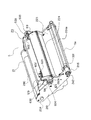
(感光ドラム及び帯電ローラの離間構成)
次に本発明に係る感光ドラム1及び帯電ローラ2の離間部材を用いた離間構成について図1を用いて詳細に説明する。図1は第1の実施の形態に係る離間部材の斜視図である。
【0092】
前述したように、感光ドラム1には帯電ローラ2が両端の軸受125を介して圧縮ばね126により所定の力で圧接されている。
【0093】
しかし、画像形成装置本体Aにプロセスカートリッジ5を装着する前(未使用)の状態においては、プロセスカートリッジ5には感光ドラム1と帯電ローラ2とを所定の間隙で離間するための離間部材500、600が取り付けられている。
【0094】
離間部材500、600は、帯電ローラ芯金の両端部2a、2bと感光ドラム1表面との間に挿入され、感光ドラム1と帯電ローラ2とを離間させるための離間部501、601を有している。
【0095】
離間部501、601は、図1に示すように、帯電ローラ芯金の両端部2a、2bと嵌合する第1凹部501a、601aと、感光ドラム1の外径に沿って円弧状に湾曲し、感光ドラム1表面と嵌合する第2凹部501b、601bが設けられている。
【0096】
そして、帯電ローラ芯金の両端部2a、2bと第1凹部501a、601a、感光ドラム1表面と第2凹部501b、601b、がそれぞれ嵌合する位置まで挿入されることにより感光ドラム1と帯電ローラ2が所定の間隙で離間される。
【0097】
また、挿入方向先端部501c、601cは、前記感光ドラム1表面と帯電ローラ芯金の両端部2a、2b間の幅に対して広くなっており、物流時などプロセスカートリッジ5に振動や衝撃が加わった際に離間部材500、600が容易に抜けてしまうのを防止する機能を有している。そしてユーザーが離間部材500、600を引き抜くと帯電ローラ2がバネの力で感光ドラム1へ押圧されるため、感光ドラム1表面を帯電可能な状態となる。
【0098】
また、離間部材500、600のプロセスカートリッジ5への挿入方向(矢印S方向(図3参照))後方には、プロセスカートリッジ5未装着時にシャッター部材119が開いてしまうのを防止するためのストッパー部502、602を有する。
【0099】
ストッパー部502、602は、感光体フレーム129に形成された離間部材500、600の挿入口(不図示)を塞ぐようフランジ状に構成され、かつシャッター部材119の一部を覆うように構成される。
【0100】
これによりプロセスカートリッジ5が装置本体Aに未装着状態において、前記離間部材挿入口の隙間から光が入り込んでしまうのを防止すると同時に、シャッター部材119を開こうとしても、シャッター部材119が離間部材500、600のストッパー部502、602に干渉するため、シャッター部材119は閉位置に保持される。
【0101】
従って、感光ドラム1は常にシャッター部材119で露出部を覆った状態となるため、光による感光層の劣化や感光ドラム1表面に傷が付いてしまうのを防止することができる。
【0102】
なお、前記離間部材挿入口はシャッター部材119の開閉方向(矢印Q方向)に対して略直角となる方向に設けられており、従って前記離間部材500、600のプロセスカートリッジ5への挿抜方向は、シャッター部材119の開閉方向に対して略直角となっている。従ってシャッター部材119を開こうとした際に離間部材500、600が抜ける方向には力がかからないように構成されている。
【0103】
また、前記ストッパー部502、602の挿入方向後方には、画像形成装置本体Aにプロセスカートリッジ5を装着する際にユーザーがプロセスカートリッジ5から離間部材500、600を取り外すための把手部503、603が形成されている。
【0104】
さらに、離間部材500、600には、離間部材500、600がプロセスカートリッジ5に取り付けられた状態において装置本体Aに装着されるのを防止するための保護部504、604を有する。
【0105】
保護部504、604は、プロセスカートリッジ5の装置本体Aへの装着位置決め部である感光体ユニット20の右側軸受106と左側軸受102を、プロセスカートリッジ5の装置本体Aへの挿入方向側から覆うよう半月形状になっている。
【0106】
そのため、離間部材500、600をプロセスカートリッジ5から取り外さないで装置本体Aに装着しようとすると、前記保護部504、604は図示しない装置本体Aのガイド部に干渉するため装着することができない。
【0107】
これにより、ユーザーがプロセスカートリッジ5を装置本体Aに装着する際には、離間部材500、600を取り外す操作が必要となるため、離間部材500、600の取り外し忘れを確実に防止することができ、さらに、プロセスカートリッジ5を装置本体Aに装着する際には、確実に感光ドラム1と帯電ローラ2との離間解除を行うことができる。
【0108】
なお、上記実施の形態は前記装着防止部504、604が装置本体Aのガイド部に干渉することにより確実に離間解除を行う構成になっているが、もし、前記装着防止部504、604が無い場合であっても、前記離間部材500、600のプロセスカートリッジ5への挿抜方向はシャッター部材119の開閉方向に対して略直角となっているため、前記離間部材500、600をプロセスカートリッジ5から取り外さないで装置本体Aに装着しようとしても、シャッター部材119は閉位置に保持され、装着することができない。したがってユーザーは離間部材500、600を取り外す操作が必要となり、離間部材500、600の取り外し忘れ防止に対しても同様の効果を発揮することができる。
【0109】
以上の構成により、プロセスカートリッジ5の未使用状態においては、感光ドラム1と帯電ローラ2との離間を保持した状態となるため、プロセスカートリッジ5を長期間に渡って作動させることなく保管しておいた際の帯電ローラ2の変形による水平の帯やムラ、或いは物流時等の振動による感光ドラム1と帯電ローラ2の摺擦メモリによる画像ムラなどの画像不良の発生を防止することができる。
【0110】
そしてプロセスカートリッジ が装置本体に未装着状態においてシャッター部材がシャッター部材119が開いてしまうのを防止するのと同時に、離間部材がプロセスカートリッジ に取り付けられた状態のままプロセスカートリッジを装置本体に装着できないようにすることで離間部材の取り外し忘れを確実に防止することができる。
【0111】
なお、本実施の形態ではより確実に離間を行うために一対の離間部材を用いた例について述べたが、感光ドラムと帯電ローラとを離間できればもちろん一つの離間部材を用いる構成であっても構わない。
【0112】
(第2の実施の形態)
次に本発明の第2の実施の形態について図9を用いて説明する。図9は第2の実施の形態に係るプロセスカートリッジの断面図である。
【0113】
前述の第1の実施の形態ではプロセスカートリッジ5の未使用状態において、感光ドラム1と帯電ローラ2とが離間を保持した状態とすると同時に、シャッター部材119が離間部材500、600のストッパー部502、602に干渉して開閉動作ができないように構成し、さらには離間部材500、600がプロセスカートリッジ5に取り付けられた状態ではプロセスカートリッジ5を装置本体Aに装着しようとすると離間部材500、600に設けられた保護部504、604が装置本体Aのガイド部に干渉するため装着ができないよう構成した例を示した。
【0114】
第2の実施の形態ではさらに離間部材700に、装置本体Aへの装着動作に連動してシャッター部材119を開閉させるためのアーム部120を覆ってプロセスカートリッジ5を画像形成装置本体Aに装着する際にシャッター部材119の開動作を防止するためのアーム保護部705を一体的に形成した構成にしている。
【0115】
ここでシャッター部材119、及び装置本体Aへの装着動作に連動してシャッター部材119を開閉させるためのアーム部120の構成を図9を用いて説明する。
【0116】
シャッター部材119は、アーム部120と結合部120bで回転可能に結合されている。
【0117】
また、アーム部120は、感光体フレーム129の側面に設けられた軸120aに回転可能に結合されており、さらに、軸120aから放射状に伸びた突起部120cを有する。
【0118】
軸120aから結合部120bへ結ぶ直線と、前記突起部120cとのなす角は約100度で構成されている。
【0119】
一方、シャッター部材119は、前記アーム部120との結合部120bから離れた位置121bにて、シャッター軸121と回転可能に結合されている。また、シャッター軸121はプロセスカートリッジ5と結合部121aにて回転可能に結合されている。そしてアーム部120はトーションバネ(不図示)によって常にシャッター部材119が閉じる方向に付勢されている。
【0120】
シャッター部材119は、プロセスカートリッジ5を装置本体Aに装着する際、アーム部120のシャッター部材119との結合部120bが、本体ガイドに設けられた第一当接部(不図示)に当接することにより開動作を始め、さらにプロセスカートリッジ5を落とし込んでいくと、アーム部120の前記突起部120cが、前記本体ガイドに設けられられた第二当接部(不図示)に当接し始めることによってシャッター部材119はさらに開きつづけ、プロセスカートリッジ5の装着が完了するとシャッター部材119の開動作も完了することとなる。
【0121】
ここで、本発明の第2の実施の形態の離間部材700をプロセスカートリッジ5に取り付けた状態で装置本体Aに装着しようとすると、前記アーム部120の結合部120bはアーム保護部705が本体ガイドの第一当接部と干渉してしまうため開動作を始めることができない。上記構成にあっては、アーム保護部705が本体ガイドの第一当接部と干渉することで離間部材700の取り外し忘れを確実に防止することができるのと同時に、アーム保護部705によりアーム部120が本体ガイドの第一当接部に当接することがなくなるので、誤って離間部材700をプロセスカートリッジ5に取り付けた状態で装置本体Aに装着しようとしてもアーム部120が壊れてしまうことがない。
【0122】
なお、本実施の形態ではより確実に離間を行うために一対の離間部材を用いた例について述べたが、感光ドラムと帯電ローラとを離間できればもちろん一つの離間部材でを用いる構成であっても構わない。
【0123】
【発明の効果】
以上説明したように本発明によれば、プロセスカートリッジの未使用状態においては感光ドラムと帯電ローラとの離間を保持した状態となるため、プロセスカートリッジを長期間に渡って作動させることなく保管しておいた際の帯電ローラの変形による水平の帯やムラ、或いは物流時等の振動による感光ドラムと帯電ローラの摺擦メモリによる画像ムラなどの画像不良が発生することはない。
【0124】
また、プロセスカートリッジが画像形成装置に未装着状態において、シャッター部材が離間部材のストッパー部に干渉して閉位置を保持するよう構成したことにより、感光ドラムは常にシャッター部材で露出部を覆った状態となり、光による感光層の劣化や感光ドラム表面に傷が付いてしまうことを防止することができる。
【0125】
さらに離間部材がプロセスカートリッジに取り付けられた状態において、プロセスカートリッジを画像形成装置に装着しようとすると離間部材に設けられた保護部が画像形成装置のガイド部に干渉するように構成したことにより、離間部材を取り外す操作が必要となり、離間部材の取り外し忘れを確実に防止することができる。つまりはプロセスカートリッジを画像形成装置に装着する際には、確実に感光ドラム及び帯電ローラの離間解除を行うことができる。
【図面の簡単な説明】
【図1】第1の実施の形態に係る離間部材の斜視図である。
【図2】本実施の形態に係る電子写真方式の画像形成装置の縦断面図である。
【図3】本実施の形態に係るプロセスカートリッジを装置前面に対して左側面から見た縦断面図である。
【図4】本実施の形態に係るプロセスカートリッジを左側から見た斜視図である。
【図5】本実施の形態に係るプロセスカートリッジを右側から見た斜視図である。
【図6】本実施の形態に係るプロセスカートリッジの構成を説明するために左側から見た分解斜視図である。
【図7】本実施の形態に係るプロセスカートリッジの構成を説明するために右側から見た分解斜視図である。
【図8】本実施の形態に係るプロセスカートリッジを装置本体に装着した際の側面方向から見た概略図である。
【図9】第2の実施の形態に係るプロセスカートリッジの断面図である。
【図10】従来の電子写真方式の画像形成装置の縦断面図である。
【符号の説明】
1 感光ドラム
2 帯電ローラ(帯電装置)
2a、2b 両端部
3 露光手段
4 現像装置
5 プロセスカートリッジ
5a 中間転写ベルト
5f クリーニング帯電ローラ
5j 一次転写ローラ
6 クリーニングブレード
8 定着装置
11 二次転写ローラ
20 感光体ユニット
21 中間転写体ユニット
102 左側軸受
106 右側軸受
119 シャッター部材
120 アーム部
120a 軸
120b 結合部
120c 突起部
121 シャッター軸
121a 結合部
121b 位置
260 左サイドカバー
260a 支持穴
260b U溝
261 右サイドカバー
261a 支持穴
261b U溝
500、600 離間部材
501、601 離間部
501a、601a 第1凹部
501b、601b 第2凹部
501c、601c 挿入方向先端部
502、602 ストッパー部
503、603 把手部
504、604 保護部
700 離間部材
701 離間部
704 保護部
705 アーム保護部
A 画像形成装置[0001]
BACKGROUND OF THE INVENTION
The present invention relates to a separation member attached to a process cartridge, a process cartridge to which the separation member is attached, and an image forming apparatus to which the process cartridge can be attached and detached.
[0002]
Here, the image forming apparatus includes, for example, an electrophotographic copying machine, an electrophotographic printer (such as an LED printer and a laser beam printer), an electrophotographic facsimile apparatus, and an electrophotographic word processor.
[0003]
The process cartridge refers to a cartridge in which the electrophotographic photosensitive member and at least one of the process means acting on the electrophotographic photosensitive member are integrated into a cartridge, and the cartridge can be attached to and detached from the image forming apparatus main body.
[0004]
[Prior art]
In an image forming apparatus using an electrophotographic image forming process, a developer image formed on a photosensitive drum as an image carrier is transferred to a recording medium to form an image. In addition, in a color image forming apparatus, In addition, there has been used a configuration in which developer images of respective colors sequentially formed on a photosensitive drum are superimposed and transferred onto an intermediate transfer member, and the color images are collectively transferred onto a recording medium. In this case, in order to make it easy to handle a deteriorated or consumed portion of the photosensitive drum or the like, a process cartridge system in which these are unitized and detachable from the main body of the image forming apparatus is widely used.
[0005]
As a conventional example of a color image forming apparatus using an intermediate transfer body, a
[0006]
As another example of a color image forming apparatus using an intermediate transfer member, as described in
[0007]
The conventional apparatus B has a configuration in which a photosensitive belt and a removed developer storage box are arranged on the lower surface of the intermediate transfer belt, and, like the conventional apparatus A, a large movable frame is rotated to the front of the apparatus. The process cartridge in which the intermediate transfer member, the photosensitive member, and the removed developer storage box are integrated is inserted from above.
[0008]
As a method for charging the surface of a photosensitive drum of a process cartridge for forming an image by these electrophotographic methods, a corona charging device has been widely put into practical use. This corona charging is effective as a method for uniformly charging the surface to be charged to a predetermined potential. However, since a high-voltage power supply is required and there is a problem of ozone generation due to corona discharge, a contact charging device that performs a charging process by bringing a charging roller into contact with the photosensitive drum surface is known as another charging method.
[0009]
Since the contact charging device needs to be installed in contact with the surface of the photosensitive drum, the contact charging device is in pressure contact with a predetermined pressing pressure.
[0010]
Therefore, if the charging roller is stored without being operated for a long period of time in this state, the charging roller is in a state where the deformation is caused only at the same portion, and in this case, the deformation due to the creep phenomenon of the rubber occurs. End up. As a result, horizontal bands and unevenness may occur on the image. In addition, image unevenness may occur due to the frictional memory between the photosensitive drum and the charging roller due to vibration during distribution.
[0011]
In order to prevent such a problem from occurring from the initial image, the rubber member of the charging roller is not deformed by sandwiching the spacer member between the core of the charging roller and the photosensitive drum and separating the charging roller from the photosensitive drum. A configuration (for example, see Patent Document 3), a method for performing pressurization and separation using a solenoid (for example, see Patent Document 4), and the like are disclosed.
[0012]
In addition, if the photosensitive drum is exposed to external light before the process cartridge is mounted on the image forming apparatus main body, an image defect may occur during initial image formation. A configuration in which a shutter of the type is provided is known.
[0013]
[Patent Document 1]
Japanese Patent Laid-Open No. 11-30944
[Patent Document 2]
Japanese Patent Laid-Open No. 10-177329
[Patent Document 3]
JP-A-2-39169
[Patent Document 4]
JP-A-6-316349
[0014]
[Problems to be solved by the invention]
However, in the case of the prior art as described above, the following problems have occurred.
[0015]
In a configuration in which the spacer member is sandwiched between the core of the charging roller and the photosensitive drum and the charging roller is separated from the photosensitive drum, the user may attach the image forming apparatus without removing the spacer member. Image forming operation is not performed.
[0016]
In addition, in the configuration in which pressurization and separation are performed using a solenoid, the configuration of the image forming apparatus is complicated, which causes an increase in cost.
[0017]
In addition, a movable shutter for preventing the photosensitive drum from being exposed to external light may remain open until the process cartridge is mounted on the image forming apparatus. Exposure may cause a defective image.
[0018]
The present invention has been made to solve the above-described problems of the prior art, and an object of the present invention is to hold a state where the photosensitive drum and the charging roller are separated from each other while the process cartridge is not used. A separation member that prevents the members from being opened and reliably releases the separation of the photosensitive drum and the charging roller when the process cartridge is attached to the main body of the image forming apparatus, and a process cartridge and an image forming apparatus including the separation member. It is to provide.
[0019]
[Means for Solving the Problems]
In order to achieve the above object, in the separation member according to the present invention,
A photosensitive drum carrying an electrostatic latent image;SaidIn contact with the photosensitive drumTheA charging roller for charging;SaidA separation member attached to a process cartridge having a shutter member covering an exposed portion of the photosensitive drum with which a process unit different from the charging roller contacts,
A separation part that is detachably sandwiched between the photosensitive drum and the charging roller, and provides a predetermined gap to separate the photosensitive drum and the charging roller;
Stopper for preventing the shutter member from openingWhen,
An arm protection unit that covers an arm unit that opens and closes the shutter member in conjunction with attachment of the process cartridge to the image forming apparatus to prevent the shutter member from opening;
SaidA protective portion for covering the positioning portion of the process cartridge that determines the mounting position while abutting against a guide portion provided in the image forming apparatus;
It is provided with.
[0020]
By attaching such a separation member, the charging roller and the photosensitive drum are separated from each other so that the charging roller is not pressed in a state where the charging roller is in contact with the photosensitive drum while the process cartridge is not used. It is possible to prevent the shutter member from being opened with a simple configuration. Further, since the user cannot attach the separation member to the image forming apparatus while attaching the separation member, forgetting to remove the separation member is prevented, and the charging roller and the photosensitive drum are reliably separated.
[0022]
In the process cartridge according to the present invention,
A process cartridge detachable from the image forming apparatus,
A photosensitive drum carrying an electrostatic latent image;
SaidIn contact with the photosensitive drumTheA charging roller for charging;
SaidA shutter member that covers an exposed portion of the photosensitive drum with which a process unit different from the charging roller contacts;
A separation portion that separates the photosensitive drum and the charging roller by providing a predetermined gap; a stopper portion for preventing the shutter member from opening;An arm protection unit that covers an arm unit that opens and closes the shutter member in conjunction with attachment of the process cartridge to the image forming apparatus to prevent the shutter member from opening;A separation unit comprising: a protection unit for covering a positioning unit of the process cartridge that determines a mounting position while contacting a guide unit provided in the image forming apparatus.Material,
TheHave
The process cartridge isThe image forming apparatusIn placeWhen not mounted, the separating portion is detachably sandwiched between the photosensitive drum and the charging roller.
[0023]
Furthermore, in the process cartridge according to the present invention,
A process cartridge detachable from the image forming apparatus,
A photosensitive drum carrying an electrostatic latent image;
SaidA charging roller that contacts and charges the photosensitive drum;
SaidThe shutter member opens the shutter member that covers the exposed portion of the photosensitive drum that is contacted by a process unit different from the charging roller, the separation portion that separates the photosensitive drum and the charging roller by providing a predetermined gap, and the shutter member opens. A stopper to preventAn arm protection unit that covers an arm unit that opens and closes the shutter member in conjunction with attachment of the process cartridge to the image forming apparatus to prevent the shutter member from opening;Spacing part withMaterial,
TheHave
The spacing member is detachably disposed in a direction substantially orthogonal to the opening / closing direction of the shutter member.
[0024]
According to this configuration, since the opening / closing direction of the shutter member is different from the direction in which the separation portion of the separation member is removed, the separation member can be prevented from coming off when an external force is applied in the opening direction of the shutter member.
[0027]
DETAILED DESCRIPTION OF THE INVENTION
Exemplary embodiments of the present invention will be described in detail below with reference to the drawings. However, the dimensions, materials, shapes, relative arrangements, and the like of the components described in this embodiment are not intended to limit the scope of the present invention only to those unless otherwise specified. Absent. Further, the materials, shapes, etc. of the members once described in the following description are the same as those in the first description unless otherwise described.
[0028]
In the following description, the “apparatus front surface” refers to the upstream surface of the recording medium transported from the transfer process to the fixing process (right side in FIG. 2), and “left and right with respect to the apparatus main body and process cartridge” Left or right when viewed from the front of the device. Further, the “longitudinal direction” is a direction that is parallel to the surface of the recording medium and intersects (substantially orthogonal) with the conveyance direction of the recording medium.
[0029]
(First embodiment)
(Overall configuration of image forming apparatus)
First, the overall configuration and operation of a color image forming apparatus that can suitably use the process cartridge according to the present invention will be schematically described with reference to FIG.
[0030]
FIG. 2 is a longitudinal sectional view showing a schematic configuration of an electrophotographic color laser beam printer in which a developing cartridge and a process cartridge including a photosensitive drum are loaded in the main body of the image forming apparatus according to an embodiment of the image forming apparatus embodying the present invention. FIG.
[0031]
The
[0032]
The developing
[0033]
A voltage having the same polarity and the same potential as the charging polarity of the
[0034]
Thereafter, a yellow toner image on the
[0035]
When the primary transfer of the yellow toner image is completed as described above, the next developing device (4M) of the developing
[0036]
Meanwhile, the
[0037]
After the four-color toner images are formed on the
[0038]
A
[0039]
A bias voltage having a polarity opposite to that of the toner is applied to the
[0040]
The recording medium onto which the toner image has been secondarily transferred in this manner is conveyed to the
[0041]
The recording medium on which the toner image is fixed is conveyed along the
[0042]
On the other hand, the
[0043]
The residual toner to which the reverse charge is applied electrostatically adheres to the
[0044]
(Developer cartridge configuration)
A developing cartridge containing toner of each color of black, magenta, yellow, and cyan is fixed at a predetermined position in the developing rotary. The rotary rotates about a central axis, and a circular rotary flange (not shown) is provided on both sides of the central axis, and the developing cartridge is fixed to the flange.
[0045]
Even if the rotary is rotated by this fixing, the developing cartridge is not detached from the rotary. When the developer cartridge is detached from the main body, the developer cartridge is pulled out with a handle (not shown). The developer cartridge is locked to both flanges of the rotary by, for example, a torsion coil spring, and can be detached and attached by a user operation.
[0046]
The developing cartridge main body is roughly divided into a toner storage portion and a developing portion. The toner storage unit is filled with toner of a predetermined color, and the agitation means rotates to convey the required amount of toner to the development unit. The conveyed toner is supplied to the surface of the developing roller by the rotation of the sponge-like toner supply roller in the developing unit, and is further thinned by being charged by the friction between the thin plate-like developing blade and the developing roller.
[0047]
The toner on the developing roller having a thin layer is conveyed to the developing unit by the rotation of the developing roller, and the electrostatic latent image formed on the photosensitive drum is visualized as a toner image by applying a predetermined developing bias.
[0048]
Residual toner that has not contributed to the visualization of the electrostatic latent image on the photosensitive drum, that is, undeveloped toner on the surface of the developing roller, is peeled off again by the toner supply roller unit, and at the same time, new toner is put on the developing roller. Then, new development operations are continuously performed.
[0049]
(Photosensitive drum, intermediate transfer member integrated process cartridge)
Next, the structure of the process cartridge having the photosensitive member unit and intermediate transfer member unit integrated structure, which is a feature of the present invention, will be described with reference to FIG. FIG. 3 is a longitudinal sectional view of the process cartridge according to the present embodiment as viewed from the left side with respect to the front surface of the apparatus.
[0050]
As shown in FIG. 3, the
[0051]
Further, the
[0052]
The
[0053]
Further, as shown in FIG. 3, the charging
[0054]
Further, the
[0055]
The scraped waste toner is prevented from falling onto the
[0056]
Thereafter, the waste toner is conveyed to the left side surface (as viewed from the front of the apparatus) of the
[0057]
The
[0058]
An
[0059]
Inside the
[0060]
Further, a
[0061]
The
[0062]
The
[0063]
(Configuration of intermediate transfer member unit 21)
Next, the configuration of the intermediate
[0064]
The
[0065]
The
[0066]
A
[0067]
At least one of the
[0068]
Further, a cleaning charging
[0069]
The
[0070]
Further, at least one of the
[0071]
(Process cartridge unit configuration)
Next, the unit configuration of the
[0072]
The frame structure is roughly divided into two. First, the
[0073]
The
[0074]
The
[0075]
Further, as shown in FIG. 8, the
[0076]
The intermediate
[0077]
A
[0078]
Next, assembly of the
[0079]
As described above, the
[0080]
Here, in the left and right side covers 260, 261 and the intermediate
[0081]
The
[0082]
Next, the metal pins 140 and 141 are press-fitted in a state where the
[0083]
At this time, the retaining
[0084]
Further, the
[0085]
The
[0086]
When the
[0087]
Further, in the intermediate
[0088]
Here, since the
[0089]
At the same time, both frame side surfaces 129a of the
[0090]
As a result, the
[0091]
(Separation structure of photosensitive drum and charging roller)
Next, the separation structure using the separation members of the
[0092]
As described above, the charging
[0093]
However, before the
[0094]
The
[0095]
As shown in FIG. 1, the
[0096]
Then, both ends 2a and 2b of the charging roller metal core and the
[0097]
Also, the insertion direction
[0098]
Further, a stopper portion for preventing the
[0099]
The
[0100]
As a result, when the
[0101]
Therefore, since the
[0102]
The separation member insertion port is provided in a direction substantially perpendicular to the opening / closing direction (arrow Q direction) of the
[0103]
Further, on the rear side of the
[0104]
Further, the
[0105]
The
[0106]
Therefore, if the
[0107]
Thereby, when the user attaches the
[0108]
In the above embodiment, the mounting
[0109]
With the above configuration, when the
[0110]
The shutter member prevents the
[0111]
In the present embodiment, an example in which a pair of separation members is used in order to perform separation more reliably has been described. However, as long as the photosensitive drum and the charging roller can be separated from each other, a configuration using one separation member may be used. Absent.
[0112]
(Second Embodiment)
Next, a second embodiment of the present invention will be described with reference to FIG. FIG. 9 is a cross-sectional view of a process cartridge according to the second embodiment.
[0113]
In the first embodiment described above, when the
[0114]
In the second embodiment, the
[0115]
Here, the configuration of the
[0116]
The
[0117]
The
[0118]
An angle formed by a straight line connecting the
[0119]
On the other hand, the
[0120]
In the
[0121]
Here, when the
[0122]
In the present embodiment, an example in which a pair of separation members is used in order to perform separation more reliably has been described. However, as long as the photosensitive drum and the charging roller can be separated from each other, of course, a single separation member may be used. I do not care.
[0123]
【The invention's effect】
As described above, according to the present invention, since the separation between the photosensitive drum and the charging roller is maintained when the process cartridge is not used, the process cartridge is stored without operating for a long period of time. Image defects such as a horizontal band or unevenness due to deformation of the charging roller when placed, or image unevenness due to frictional memory between the photosensitive drum and the charging roller due to vibration during distribution or the like do not occur.
[0124]
Also, the process cartridgeImage forming apparatusWhen the shutter member is not attached to the photosensitive member, the shutter member interferes with the stopper portion of the separation member to hold the closed position.IsAlways shutterWith woodThe exposed portion is covered, and it is possible to prevent the photosensitive layer from being deteriorated by light and from scratching the surface of the photosensitive drum.
[0125]
Further, with the separation member attached to the process cartridge, the process cartridgeImage forming apparatusThe protective part provided on the separating member isImage forming apparatusSince it is configured to interfere with the guide portion, an operation for removing the spacing member is required, and forgetting to remove the spacing member can be reliably prevented. In other words, process cartridgeThe image forming deviceWhen mounted on the photosensitive drum, it is possible to reliably release the separation between the photosensitive drum and the charging roller.
[Brief description of the drawings]
FIG. 1 is a perspective view of a separation member according to a first embodiment.
FIG. 2 is a longitudinal sectional view of an electrophotographic image forming apparatus according to the present embodiment.
FIG. 3 is a longitudinal sectional view of the process cartridge according to the present embodiment as viewed from the left side with respect to the front surface of the apparatus.
FIG. 4 is a perspective view of the process cartridge according to the present embodiment as viewed from the left side.
FIG. 5 is a perspective view of the process cartridge according to the present embodiment as viewed from the right side.
FIG. 6 is an exploded perspective view seen from the left side for explaining the configuration of the process cartridge according to the present embodiment.
FIG. 7 is an exploded perspective view seen from the right side for explaining the configuration of the process cartridge according to the present embodiment.
FIG. 8 is a schematic view seen from the side when the process cartridge according to the present embodiment is mounted on the apparatus main body.
FIG. 9 is a cross-sectional view of a process cartridge according to a second embodiment.
FIG. 10 is a longitudinal sectional view of a conventional electrophotographic image forming apparatus.
[Explanation of symbols]
1 Photosensitive drum
2 Charging roller (charging device)
2a, 2b both ends
3 Exposure means
4 Development device
5 Process cartridge
5a Intermediate transfer belt
5f Cleaning charging roller
5j Primary transfer roller
6 Cleaning blade
8 Fixing device
11 Secondary transfer roller
20 Photosensitive unit
21 Intermediate transfer unit
102 Left side bearing
106 Right side bearing
119 Shutter member
120 Arm
120a axis
120b coupling part
120c protrusion
121 Shutter axis
121a coupling part
121b position
260 Left side cover
260a Support hole
260b U groove
261 Right side cover
261a Support hole
261b U groove
500, 600 Spacing member
501, 601 Separation part
501a, 601a First recess
501b, 601b Second recess
501c, 601c Insertion direction tip
502, 602 Stopper part
503, 603 Handle part
504, 604 Protection part
700 Spacing member
701 Spacing part
704 Protection part
705 Arm protector
A Image forming apparatus
Claims (3)
前記感光ドラムと前記帯電ローラとの間に取り外し可能に挟持され、所定の間隙を設けて前記感光ドラムと前記帯電ローラとを離間する離間部と、
前記シャッター部材が開いてしまうことを防止するためのストッパー部と、
前記シャッター部材が開いてしまうことを防止するための、画像形成装置への前記プロセスカートリッジの装着に連動して前記シャッター部材を開閉させるアーム部を覆うアーム保護部と、
前記画像形成装置に設けられたガイド部に当接しながら装着位置を決める前記プロセスカートリッジの位置決め部を覆うための保護部と、
を備えたことを特徴とする離間部材。A photosensitive drum carrying an electrostatic latent image, the process has a charging roller for charging in contact with the photosensitive drum, and a shutter member that covers an exposed portion of the photosensitive drum, wherein the charging roller and the different process unit abuts cartridge A spacing member attached to
A separation portion that is detachably sandwiched between the photosensitive drum and the charging roller, and that separates the photosensitive drum and the charging roller by providing a predetermined gap;
A stopper portion for preventing the shutter member from opening ;
An arm protection unit that covers an arm unit that opens and closes the shutter member in conjunction with attachment of the process cartridge to the image forming apparatus to prevent the shutter member from opening;
A protective portion for covering the positioning portion of said process cartridge to determine the contact with the mounting position on the guide portion provided in the image forming apparatus,
A spacing member comprising:
静電潜像を担持する感光ドラムと、
前記感光ドラムに接触して帯電する帯電ローラと、
前記帯電ローラと異なるプロセス手段が当接する前記感光ドラムの露出部を覆うシャッター部材と、
所定の間隙を設けて前記感光ドラムと前記帯電ローラとを離間する離間部と、前記シャッター部材が開いてしまうことを防止するためのストッパー部と、前記シャッター部材が開いてしまうことを防止するための、前記画像形成装置への前記プロセスカートリッジの装着に連動して前記シャッター部材を開閉させるアーム部を覆うアーム保護部と、前記画
像形成装置に設けられたガイド部に当接しながら装着位置を決める前記プロセスカートリッジの位置決め部を覆うための保護部と、を備える離間部材と、
を有し、
前記プロセスカートリッジが前記画像形成装置に装着されていない場合に、前記離間部を前記感光ドラムと前記帯電ローラとの間に取り外し可能に挟持したことを特徴とするプロセスカートリッジ。 A process cartridge detachable from the image forming apparatus,
A photosensitive drum carrying an electrostatic latent image;
A charging roller for charging in contact with the photosensitive drum,
A shutter member covering an exposed portion of the photosensitive drum with which a process unit different from the charging roller contacts;
In order to prevent the shutter member from opening, a separation portion for providing a predetermined gap to separate the photosensitive drum and the charging roller, a stopper portion for preventing the shutter member from opening, and the like. An arm protection unit that covers an arm unit that opens and closes the shutter member in conjunction with the mounting of the process cartridge to the image forming apparatus, and a guide unit that is provided in the image forming apparatus. a spacing member comprising a protective portion for covering the positioning portion of said process cartridge to determine the mounting position while,
Have,
When said process cartridge is not mounted to the image forming equipment, a process cartridge, characterized in that the spaced portion is capable clamped releasably between the charging roller and the photosensitive drum.
静電潜像を担持する感光ドラムと、
前記感光ドラムに接触し帯電する帯電ローラと、
前記帯電ローラと異なるプロセス手段が当接する前記感光ドラムの露出部を覆うシャッター部材と、所定の間隙を設けて前記感光ドラムと前記帯電ローラとを離間する離間部と、前記シャッター部材が開いてしまうことを防止するためのストッパー部と、前記シャッター部材が開いてしまうことを防止するための、前記画像形成装置への前記プロセスカートリッジの装着に連動して前記シャッター部材を開閉させるアーム部を覆うアーム保護部と、を備える離間部材と、
を有し、
前記離間部材は、前記シャッター部材の開閉方向に対して略直交する方向に取り外し可能に配置されることを特徴とするプロセスカートリッジ。 A process cartridge detachable from the image forming apparatus,
A photosensitive drum carrying an electrostatic latent image;
A charging roller which contacts charged on the photosensitive drum,
The shutter member opens the shutter member that covers the exposed portion of the photosensitive drum with which the process means different from the charging roller abuts, the separation portion that separates the photosensitive drum and the charging roller by providing a predetermined gap, and the shutter member opens. An arm that covers a stopper portion for preventing the shutter member and an arm portion for opening and closing the shutter member in conjunction with the attachment of the process cartridge to the image forming apparatus for preventing the shutter member from opening. a spacing member comprising a protection unit,
Have,
The process cartridge according to claim 1, wherein the separation member is detachably disposed in a direction substantially orthogonal to the opening / closing direction of the shutter member.
Priority Applications (2)
| Application Number | Priority Date | Filing Date | Title |
|---|---|---|---|
| JP2002286915A JP3984900B2 (en) | 2002-09-30 | 2002-09-30 | Spacing member and process cartridge |
| US10/671,696 US6937834B2 (en) | 2002-09-30 | 2003-09-29 | Spacing member, process cartridge, and electrophotographic image forming apparatus |
Applications Claiming Priority (1)
| Application Number | Priority Date | Filing Date | Title |
|---|---|---|---|
| JP2002286915A JP3984900B2 (en) | 2002-09-30 | 2002-09-30 | Spacing member and process cartridge |
Publications (2)
| Publication Number | Publication Date |
|---|---|
| JP2004125951A JP2004125951A (en) | 2004-04-22 |
| JP3984900B2 true JP3984900B2 (en) | 2007-10-03 |
Family
ID=32279865
Family Applications (1)
| Application Number | Title | Priority Date | Filing Date |
|---|---|---|---|
| JP2002286915A Expired - Fee Related JP3984900B2 (en) | 2002-09-30 | 2002-09-30 | Spacing member and process cartridge |
Country Status (2)
| Country | Link |
|---|---|
| US (1) | US6937834B2 (en) |
| JP (1) | JP3984900B2 (en) |
Families Citing this family (32)
| Publication number | Priority date | Publication date | Assignee | Title |
|---|---|---|---|---|
| KR100555751B1 (en) * | 2004-01-05 | 2006-03-03 | 삼성전자주식회사 | Process Cartridge of Image Forming Device |
| JP2005266126A (en) * | 2004-03-17 | 2005-09-29 | Fuji Xerox Co Ltd | Image forming unit and method of manufacturing the same |
| JP4124153B2 (en) * | 2004-03-31 | 2008-07-23 | ブラザー工業株式会社 | Process cartridge and image forming apparatus |
| JP3986077B2 (en) * | 2005-03-18 | 2007-10-03 | キヤノン株式会社 | Process cartridge and electrophotographic image forming apparatus |
| JP4537960B2 (en) * | 2006-01-24 | 2010-09-08 | 株式会社沖データ | Separating member and image forming apparatus having the separating member |
| JP4241865B2 (en) | 2006-12-08 | 2009-03-18 | キヤノン株式会社 | Process cartridge and electrophotographic image forming apparatus |
| US7929881B2 (en) * | 2006-12-11 | 2011-04-19 | Canon Kabushiki Kaisha | Process cartridge and electrophotographic image forming apparatus |
| JP5084257B2 (en) * | 2006-12-28 | 2012-11-28 | キヤノン株式会社 | Process cartridge and image forming apparatus using the same |
| JP4458377B2 (en) | 2007-06-29 | 2010-04-28 | キヤノン株式会社 | Process cartridge and electrophotographic image forming apparatus |
| US8045885B2 (en) * | 2007-09-13 | 2011-10-25 | Kabushiki Kaisha Toshiba | Processing unit for image forming apparatus |
| JP4968957B2 (en) * | 2008-03-31 | 2012-07-04 | キヤノン株式会社 | Frame body unit, developing device and process cartridge, and frame body unit, developing device and process cartridge manufacturing method |
| JP4701266B2 (en) * | 2008-05-27 | 2011-06-15 | キヤノン株式会社 | Process cartridge and electrophotographic image forming apparatus |
| JP2010060613A (en) * | 2008-09-01 | 2010-03-18 | Canon Inc | Drum cartridge and electrophotographic image-forming apparatus |
| JP4663802B2 (en) * | 2008-09-01 | 2011-04-06 | キヤノン株式会社 | Cover member and cartridge |
| WO2010024471A1 (en) | 2008-09-01 | 2010-03-04 | キヤノン株式会社 | Developing cartridge, process cartridge, and electrophotographic image forming apparatus |
| JP4954262B2 (en) * | 2009-10-30 | 2012-06-13 | キヤノン株式会社 | Electrophotographic image forming apparatus |
| JP4954261B2 (en) * | 2009-10-30 | 2012-06-13 | キヤノン株式会社 | Electrophotographic image forming apparatus |
| JP2011123348A (en) * | 2009-12-11 | 2011-06-23 | Canon Inc | Process cartridge and method for disassembling process cartridge |
| JP2011191427A (en) * | 2010-03-12 | 2011-09-29 | Fuji Xerox Co Ltd | Image forming cartridge and image forming device |
| KR101772967B1 (en) * | 2011-01-12 | 2017-08-31 | 에스프린팅솔루션 주식회사 | Developing unit and image forming apparatus using the same |
| JP5831048B2 (en) | 2011-08-30 | 2015-12-09 | ブラザー工業株式会社 | Image forming apparatus |
| JP5355679B2 (en) | 2011-12-27 | 2013-11-27 | キヤノン株式会社 | Process cartridge and image forming apparatus |
| PL3486730T3 (en) | 2012-06-15 | 2021-01-11 | Canon Kabushiki Kaisha | Cartridge, process cartridge and electrophotographic image forming apparatus |
| JP6128780B2 (en) | 2012-09-05 | 2017-05-17 | キヤノン株式会社 | Developing device and cartridge |
| JP2014237472A (en) | 2013-06-07 | 2014-12-18 | キヤノン株式会社 | Packing member and cartridge packed in the same |
| JP6338460B2 (en) | 2013-08-20 | 2018-06-06 | キヤノン株式会社 | Cartridge and image forming apparatus |
| JP6376749B2 (en) | 2013-12-06 | 2018-08-22 | キヤノン株式会社 | Process cartridge and electrophotographic image forming apparatus |
| JP6671997B2 (en) | 2015-02-05 | 2020-03-25 | キヤノン株式会社 | Cartridge, photoreceptor unit, electrophotographic image forming apparatus |
| JP6598468B2 (en) | 2015-02-16 | 2019-10-30 | キヤノン株式会社 | Cartridge, image forming apparatus, and cartridge manufacturing method |
| JP6552212B2 (en) | 2015-02-16 | 2019-07-31 | キヤノン株式会社 | Cartridge, image forming apparatus, and method of manufacturing cartridge |
| JP6855284B2 (en) | 2017-03-03 | 2021-04-07 | キヤノン株式会社 | Cartridge and image forming device |
| CA3125097A1 (en) | 2019-03-18 | 2020-09-24 | Canon Kabushiki Kaisha | Electrophotographic image forming apparatus and cartridge |
Family Cites Families (30)
| Publication number | Priority date | Publication date | Assignee | Title |
|---|---|---|---|---|
| JPH0239169A (en) | 1988-07-29 | 1990-02-08 | Canon Inc | Contact electrifying device |
| JPH06316349A (en) | 1993-04-01 | 1994-11-15 | Sharp Corp | Pressure control device for pressure member |
| JP2877728B2 (en) * | 1994-04-28 | 1999-03-31 | キヤノン株式会社 | Process cartridge and image forming apparatus |
| JPH0815940A (en) * | 1994-04-28 | 1996-01-19 | Canon Inc | Developing frame, process cartridge and image forming device |
| JP2877729B2 (en) * | 1994-04-28 | 1999-03-31 | キヤノン株式会社 | Shutter member, process cartridge, and image forming apparatus |
| CN1093946C (en) * | 1995-07-21 | 2002-11-06 | 佳能株式会社 | Electrod assembly, developing device, processing card box and imaging equipment |
| US5893006A (en) * | 1995-07-31 | 1999-04-06 | Canon Kabushiki Kaisha | Process cartridge detectably mountable to image forming apparatus and image forming apparatus using same |
| JP3402860B2 (en) * | 1995-07-31 | 2003-05-06 | キヤノン株式会社 | Process cartridge and electrophotographic image forming apparatus |
| US6070029A (en) * | 1995-07-31 | 2000-05-30 | Canon Kabushiki Kaisha | Coupling member, process cartridge, electrophotographic image forming apparatus and assembling method |
| JP3869901B2 (en) * | 1996-03-05 | 2007-01-17 | キヤノン株式会社 | Developing cartridge and electrophotographic image forming apparatus |
| JP3869902B2 (en) * | 1996-03-05 | 2007-01-17 | キヤノン株式会社 | Developing cartridge and electrophotographic image forming apparatus |
| US6072969A (en) * | 1996-03-05 | 2000-06-06 | Canon Kabushiki Kaisha | Developing cartridge |
| JP3332818B2 (en) * | 1996-08-29 | 2002-10-07 | キヤノン株式会社 | Process cartridge, electrophotographic image forming apparatus, and connection terminal connection method |
| JP3490581B2 (en) | 1996-12-16 | 2004-01-26 | 株式会社リコー | Process unit and image forming apparatus |
| JPH1130944A (en) | 1997-07-10 | 1999-02-02 | Ricoh Co Ltd | Process cartridge unit and attaching/detaching structure thereof |
| JP3658202B2 (en) * | 1998-08-31 | 2005-06-08 | キヤノン株式会社 | Developing cartridge assembly method |
| JP3893222B2 (en) * | 1998-08-31 | 2007-03-14 | キヤノン株式会社 | Shutter pin and developer cartridge |
| JP3293818B2 (en) * | 1999-05-20 | 2002-06-17 | キヤノン株式会社 | Process cartridge and electrophotographic image forming apparatus |
| JP3320398B2 (en) * | 1999-05-20 | 2002-09-03 | キヤノン株式会社 | Process cartridge and electrophotographic image forming apparatus |
| JP3320399B2 (en) * | 1999-05-20 | 2002-09-03 | キヤノン株式会社 | Process cartridge, method of assembling process cartridge, and electrophotographic image forming apparatus |
| JP2001159841A (en) * | 1999-12-01 | 2001-06-12 | Canon Inc | Developing cartridge, process cartridge and electrophotographic image forming device |
| US6549736B2 (en) * | 2000-01-19 | 2003-04-15 | Canon Kabushiki Kaisha | Process cartridge, engaging member therefor and method for mounting developing roller and magnet |
| JP2001281996A (en) * | 2000-04-03 | 2001-10-10 | Canon Inc | Developing cartridge, processing cartridge and electrophotographic image forming device |
| CN1237416C (en) * | 2000-06-09 | 2006-01-18 | 佳能株式会社 | Connection method between developing device, process cartridge, developing frame, and developer frame, and flexible seal |
| JP2002006609A (en) * | 2000-06-26 | 2002-01-11 | Canon Inc | Toner sealing member, developing cartridge, process cartridge and electrophotographic image forming device |
| JP2002023476A (en) * | 2000-07-07 | 2002-01-23 | Canon Inc | Developing cartridge, process cartridge and electrophotographic image forming device |
| JP3658315B2 (en) * | 2000-12-19 | 2005-06-08 | キヤノン株式会社 | Process cartridge and electrophotographic image forming apparatus |
| JP2002229306A (en) * | 2001-01-31 | 2002-08-14 | Canon Inc | Electrifying device, image forming device and processing cartridge |
| JP3566697B2 (en) | 2001-02-09 | 2004-09-15 | キヤノン株式会社 | Process cartridge, electrophotographic image forming apparatus, and separation mechanism |
| US6834173B2 (en) * | 2001-11-05 | 2004-12-21 | Canon Kabushiki Kaisha | Image-forming-apparatus process cartridge having a locking portion to prevent the cartridge from disengaging from the image forming apparatus and an image forming apparatus mounting such a cartridge |
-
2002
- 2002-09-30 JP JP2002286915A patent/JP3984900B2/en not_active Expired - Fee Related
-
2003
- 2003-09-29 US US10/671,696 patent/US6937834B2/en not_active Expired - Fee Related
Also Published As
| Publication number | Publication date |
|---|---|
| US20040126135A1 (en) | 2004-07-01 |
| JP2004125951A (en) | 2004-04-22 |
| US6937834B2 (en) | 2005-08-30 |
Similar Documents
| Publication | Publication Date | Title |
|---|---|---|
| JP3984900B2 (en) | Spacing member and process cartridge | |
| JP3745327B2 (en) | Process cartridge remanufacturing method | |
| US8000630B2 (en) | Developing cartridge, process cartridge, and electrophotographic image forming apparatus | |
| CN101566820B (en) | Image forming apparatus | |
| JP3757736B2 (en) | Process cartridge and image forming apparatus using the same | |
| JP3997250B2 (en) | Process cartridge | |
| JP4663097B2 (en) | Electrophotographic image forming apparatus | |
| JP3984978B2 (en) | Process cartridge and electrophotographic image forming apparatus | |
| JP2002304104A (en) | Imaging device | |
| US7706719B2 (en) | Image forming apparatus with an openable section at an upper face side or a front face side | |
| JP4666713B2 (en) | Image forming unit | |
| CN102023508B (en) | Image-forming apparatus | |
| JP2000227688A (en) | Processing unit and image forming device provided therewith | |
| JP5370922B2 (en) | Developing device, process unit, image forming apparatus, and assembling method of developing device | |
| JP2004126030A (en) | Process cartridge and electrophotographic image forming apparatus | |
| JP2003195721A (en) | Process cartridge and image forming apparatus | |
| JP2003195729A (en) | Process cartridge and image forming apparatus | |
| JPH10115961A (en) | Image forming device | |
| JP3658444B2 (en) | Color image forming apparatus | |
| JP3714582B2 (en) | Image forming apparatus | |
| JP4978029B2 (en) | Image forming apparatus | |
| JP3997196B2 (en) | Process cartridge and developing separation member | |
| JP2001305827A (en) | Image forming device | |
| JP2003316170A (en) | Cleaner unit and image forming apparatus | |
| JP4051914B2 (en) | Image forming apparatus |
Legal Events
| Date | Code | Title | Description |
|---|---|---|---|
| A621 | Written request for application examination |
Free format text: JAPANESE INTERMEDIATE CODE: A621 Effective date: 20050819 |
|
| A977 | Report on retrieval |
Free format text: JAPANESE INTERMEDIATE CODE: A971007 Effective date: 20070404 |
|
| A131 | Notification of reasons for refusal |
Free format text: JAPANESE INTERMEDIATE CODE: A131 Effective date: 20070410 |
|
| A521 | Request for written amendment filed |
Free format text: JAPANESE INTERMEDIATE CODE: A523 Effective date: 20070604 |
|
| TRDD | Decision of grant or rejection written | ||
| A01 | Written decision to grant a patent or to grant a registration (utility model) |
Free format text: JAPANESE INTERMEDIATE CODE: A01 Effective date: 20070626 |
|
| A61 | First payment of annual fees (during grant procedure) |
Free format text: JAPANESE INTERMEDIATE CODE: A61 Effective date: 20070709 |
|
| FPAY | Renewal fee payment (event date is renewal date of database) |
Free format text: PAYMENT UNTIL: 20100713 Year of fee payment: 3 |
|
| R150 | Certificate of patent or registration of utility model |
Free format text: JAPANESE INTERMEDIATE CODE: R150 |
|
| FPAY | Renewal fee payment (event date is renewal date of database) |
Free format text: PAYMENT UNTIL: 20100713 Year of fee payment: 3 |
|
| FPAY | Renewal fee payment (event date is renewal date of database) |
Free format text: PAYMENT UNTIL: 20110713 Year of fee payment: 4 |
|
| FPAY | Renewal fee payment (event date is renewal date of database) |
Free format text: PAYMENT UNTIL: 20120713 Year of fee payment: 5 |
|
| FPAY | Renewal fee payment (event date is renewal date of database) |
Free format text: PAYMENT UNTIL: 20120713 Year of fee payment: 5 |
|
| FPAY | Renewal fee payment (event date is renewal date of database) |
Free format text: PAYMENT UNTIL: 20130713 Year of fee payment: 6 |
|
| LAPS | Cancellation because of no payment of annual fees |