JP3970543B2 - Air intake structure of motorcycle - Google Patents
Air intake structure of motorcycle Download PDFInfo
- Publication number
- JP3970543B2 JP3970543B2 JP2001105698A JP2001105698A JP3970543B2 JP 3970543 B2 JP3970543 B2 JP 3970543B2 JP 2001105698 A JP2001105698 A JP 2001105698A JP 2001105698 A JP2001105698 A JP 2001105698A JP 3970543 B2 JP3970543 B2 JP 3970543B2
- Authority
- JP
- Japan
- Prior art keywords
- air
- motorcycle
- air inlet
- inclined surface
- pipe
- Prior art date
- Legal status (The legal status is an assumption and is not a legal conclusion. Google has not performed a legal analysis and makes no representation as to the accuracy of the status listed.)
- Expired - Fee Related
Links
- 230000003584 silencer Effects 0.000 description 16
- 238000003825 pressing Methods 0.000 description 4
- 238000004891 communication Methods 0.000 description 3
- 238000007796 conventional method Methods 0.000 description 3
- 238000005192 partition Methods 0.000 description 3
- 230000000694 effects Effects 0.000 description 2
- 238000005516 engineering process Methods 0.000 description 2
- 230000002238 attenuated effect Effects 0.000 description 1
- 238000001816 cooling Methods 0.000 description 1
- 239000002828 fuel tank Substances 0.000 description 1
- 230000005484 gravity Effects 0.000 description 1
- 230000002452 interceptive effect Effects 0.000 description 1
- 238000000034 method Methods 0.000 description 1
- 230000002265 prevention Effects 0.000 description 1
- 238000005096 rolling process Methods 0.000 description 1
Images


Classifications
-
- B—PERFORMING OPERATIONS; TRANSPORTING
- B62—LAND VEHICLES FOR TRAVELLING OTHERWISE THAN ON RAILS
- B62J—CYCLE SADDLES OR SEATS; AUXILIARY DEVICES OR ACCESSORIES SPECIALLY ADAPTED TO CYCLES AND NOT OTHERWISE PROVIDED FOR, e.g. ARTICLE CARRIERS OR CYCLE PROTECTORS
- B62J17/00—Weather guards for riders; Fairings or stream-lining parts not otherwise provided for
- B62J17/10—Ventilation or air guiding devices forming part of fairings
-
- B—PERFORMING OPERATIONS; TRANSPORTING
- B62—LAND VEHICLES FOR TRAVELLING OTHERWISE THAN ON RAILS
- B62J—CYCLE SADDLES OR SEATS; AUXILIARY DEVICES OR ACCESSORIES SPECIALLY ADAPTED TO CYCLES AND NOT OTHERWISE PROVIDED FOR, e.g. ARTICLE CARRIERS OR CYCLE PROTECTORS
- B62J17/00—Weather guards for riders; Fairings or stream-lining parts not otherwise provided for
- B62J17/02—Weather guards for riders; Fairings or stream-lining parts not otherwise provided for shielding only the rider's front
Landscapes
- Engineering & Computer Science (AREA)
- Mechanical Engineering (AREA)
- Automatic Cycles, And Cycles In General (AREA)
Description
【0001】
【発明の属する技術分野】
本発明は自動二輪車のエア吸入口構造に関する。
【0002】
【従来の技術】
自動二輪車の吸気系構造は、車体の前部を覆うカウリングにエア吸入口を設け、このエア吸入口から延ばしたエアダクトの先をエアクリーナに接続するようにしたものである。このような自動二輪車の排気系構造としては、例えば特開平9−86463号公報「自動二輪車」(以下、「従来の技術▲1▼」と言う)が知られている。
【0003】
上記従来の技術▲1▼は、同公報の図1〜図3に示される通り、アッパーカウリング12(番号は公報に記載されたものを引用した。以下同じ。)の前部の車幅中央位置に1つの空気入口17を設け、この空気入口17から後方へ分岐ダクト18を延ばし、分岐ダクト18の先にエアクリーナ16を接続するようにした吸気系構造に関する。
【0004】
しかしながら上記従来の技術▲1▼は、車幅中央位置に1つの空気入口17だけを設けたのであるから、空気入口17の開口面積を増すには限界がある。
また、前輪3がもっとも持上がったときであっても、前輪3に空気入口17が干渉しないようにする必要がある。干渉しないように空気入口17の高さを上げると、自動二輪車1全体の高さも上がる結果になり、得策ではない。
【0005】
このような点を解消するためには、例えば特開2000−95168号公報「自動二輪車の走行風ダクト取付構造」(以下、「従来の技術▲2▼」と言う)のような構成にすることが考えられる。
【0006】
上記従来の技術▲2▼は、同公報の図1及び図2に示される通り、カウリング16の前部に左右2つの空気取入口17,17を設け、これらの空気取入口17,17から後方へ走行風ダクト18,18を延ばし、走行風ダクト18,18の先にエアクリーナ7を接続するようにした吸気系構造に関する。自動二輪車1を走行中にカウリング16の前面に発生した走行風を、空気取入口17,17から取入れることができる。
上記従来の技術▲2▼によれば、空気取入口17,17を左右に配置するので、空気取入口17,17の開口面積を増す上で有利になるとともに、前輪10に空気取入口17,17が干渉することはない。
【0007】
【発明が解決しようとする課題】
上記従来の技術▲2▼において、空気取入口17,17に入らぬ走行風は、カウリング16に沿って後方へ流れる。しかしながら、カウリング16は全体的に丸みを有して膨出した形状を呈している。空気取入口17,17に入らぬ走行風が、カウリング16に当って乱流になり得る。このような乱流を低減することが、自動二輪車1の走行性能を高める上で有利である。
上記従来の技術▲1▼についても同様である。
【0008】
そこで本発明の目的は、(1)カウリングに設けるエア吸入口の開口面積を増すことによって、エアをエンジンへ十分に供給するとともに、(2)エア吸入口に入らぬエアを整流しつつ後方へ流せるようにすることができる技術を提供することにある。
【0009】
【課題を解決するための手段】
上記目的を達成するために請求項1は、車体の前部を覆うカウリングにエア吸入口を設け、このエア吸入口から延ばしたエアダクトの先をエアクリーナに接続するようにした自動二輪車において、エア吸入口が、フロントフォークの左右の外側位置に各々設け、側面視でくの字を呈する切込み部をカウリングに且つエア吸入口の外側に隣接して設け、エア吸入口に入らぬエアを切込み部に沿わせて流せるようにしたことを特徴とする。
【0010】
エア吸入口を、フロントフォークの左右の外側位置に各々設けたので、エア吸入口の開口面積を増す上で、周囲の他の部材のレイアウトの制限を受けにくい。このため、エア吸入口の開口面積を増してエアをエンジンへ十分に供給することができる。この結果、エンジン性能をより十分に発揮させることができる。
しかも、車幅中央にある前輪に対して、エア吸入口を左右に設けたので、前輪がもっとも持上がったときであっても、前輪にエア吸入口が干渉することはない。従って、エア吸入口の高さを上げる必要がないので、自動二輪車のデザイン上の制約がない。
さらには、側面視でくの字を呈する切込み部をカウリングに且つエア吸入口の外側に隣接して設け、エア吸入口に入らぬエアを切込み部に沿わせて流せるようにしたので、エア吸入口に入らぬエアを整流しつつ後方へ流すことができる。従って、自動二輪車の走行性能を高める上で有利である。
請求項2では、切込み部は、下側傾斜面及び上側傾斜面から構成され、下側傾斜面は、正面から後方へ向って上向きとなる傾斜面であることを特徴とする。
正面から後方へ向って上向きとなる傾斜面である下側傾斜面に走行時のエアを通過させることによって、自動二輪車を下方へ押え付けるための下向き力を発生させる。この結果、走行時に発生する揚力を下向き力によって軽減することができる。従って、前輪のタイヤのグリップ力を維持して、快適な高速走行性能を得ることができる。
請求項3では、エア吸入口は、車体正面視、略三角形状で、前輪に向けた辺が湾曲していることをことを特徴とする。
前輪がもっとも持上がったときであっても、前輪にエア吸入口が干渉することはない。従って、エア吸入口の高さを上げる必要がないので、自動二輪車のデザイン上の制約がない。
【0011】
【発明の実施の形態】
本発明の実施の形態を添付図面に基づいて以下に説明する。
なお、「前」、「後」、「左」、「右」、「上」、「下」は運転者から見た方向に従う。また、図面は符号の向きに見るものとする。
【0012】
図1は本発明に係る自動二輪車の右側面図であり、自動二輪車10の外観を示す。
自動二輪車10は、車体フレーム20の前部にフロントフォーク31を介して取付けた前輪32と、車体フレーム20の後部にスイングアーム33を介して取付けた後輪34と、車体フレーム20の長手中央下部に取付けたエンジン40と、車体フレーム20の長手中央上部に取付けたエアクリーナ53、燃料タンク55並びにシート56とを備える。
【0013】
本発明は、前・後輪32,34間にエンジン40を配置するとともに、エンジン40の下方にサイレンサ70を配置したことを特徴とする。サイレンサ70は、車体フレーム20又はエンジン40に取付けることになる。
【0014】
また、自動二輪車10のカウリング100は、車体前部の上部を覆うフロントカウル101と、車体前部の中部を覆う左右のミドルカウル111(この図では右のみ示す。以下同じ。)と、車体下部並びにサイレンサ70の側面を覆う左右のロアカウル121と、車体後部を囲うリヤカウル131とからなる。
【0015】
フロントカウル101と左右のミドルカウル111と左右のロアカウル121とは、ビス止めによって分割可能に結合し合う。詳しく述べると、カウリング100は、フロントカウル101の下部に対し左右のミドルカウル(前側カウル)111の上部前部を分割可能にし、また、サイレンサ70の前方位置で、ミドルカウル111の下部後端部に対しロアカウル(後側カウル)121の前端部を分割可能にしたものである。
【0016】
フロントカウル101は、上部にウインドスクリーン102を備えるとともに、前部に左右一対のエア吸入口103を備える。
また、ミドルカウル(前側カウル)111の下部後端に車体中心に向って窪む窪み112を形成し、ロアカウル(後側カウル)121の前端に前面開口部122を形成し、この前面開口部122と窪み112とを合せることで、サイレンサ70を冷却するための大きな導風口123を形成することができる。
【0017】
さらにこの図は、リヤカウル131の下方に配置するリヤフェンダ140をスイングアーム33に取付けたことを示す。本発明は、リヤカウル131の下縁132を後上方へほぼ直線的に傾斜させ、リヤフェンダ140の上面141をリヤカウル131の下縁132に平行になるように後上方へほぼ直線的に傾斜させたことを特徴とする。
【0018】
図中、47はエンジンのクランク軸、48はカバー部材(クランク軸カバー)、91はハンドル、92はミラー、93はヘッドランプ、94はウインカ、95はフロントフェンダ、96はリヤクッションユニット、97はクッション用リンクである。上記サイレンサ70の後部は、クッション用リンク97の近傍まで延びる。
【0019】
図2は本発明に係る自動二輪車の吸・排気系構造の要部斜視図である。
自動二輪車10の吸気系51は、上記図1に示すフロントカウル101に設けた左右一対のエア吸入口103と、これらのエア吸入口103から後方へ延ばした左右一対のエアダクト(吸気ダクト)52,52と、これらのエアダクト52,52の先に接続したエアクリーナ53とからなる。エアクリーナ53を、車体フレーム20の左右一対のメインパイプ21,21間に配置するようにした。22はヘッドパイプである。
【0020】
エンジン40は、上部前部に4つの排気口41〜44を左右1列に配列した4気筒エンジンであり、下部後部にオイルパン45を備える。
自動二輪車10の排気系58は、エンジン40の排気口41〜44から延ばしたエキゾーストパイプ60並びにこのエキゾーストパイプ60に接続したサイレンサ70を介して排気ガスを排出する装置である。
【0021】
サイレンサ70としては、ガス入口73の近傍にガス出口74を設けた形式のものを採用する。ガス入口73を後輪34側に臨ませた状態でサイレンサ70をエンジン40の下方に配置するとともに、エキゾーストパイプ60を後輪34の近傍まで延ばした状態でサイレンサ70のガス入口73に接続するようにした。
【0022】
ここで、4つの排気口については、車体左側(この図の右側)から右側へこの順に第1排気口41、第2排気口42、第3排気口43、第4排気口44と言う。
エキゾーストパイプ60は、4つのパイプ(第1パイプ61、第2パイプ62、第3パイプ63及び第4パイプ64)と、3つの集合筒(第1集合筒65、第2集合筒66及び第3集合筒67)とからなる。
【0023】
第1排気口41に一端を接続した第1パイプ61は、右下方へ延びた後に、更にオイルパン45の右側を通りつつ後方へ延びる。同様に、第2排気口42に一端を接続した第2パイプ62も、右下方へ延びた後に、更にオイルパン45の右側を通りつつ後方へ延びる。そして、第1パイプ61の他端と第2パイプ62の他端とを、第1集合筒65に接続することで1つに集合する。第1集合筒65は、オイルパン45の右側を通りつつ後方へ延びた後に、更に左へ延びる。
【0024】
一方、第3排気口43に一端を接続した第3パイプ63は、左下方へ延びた後に、更にオイルパン45の左側を通りつつ後方へ延びる。同様に、第4排気口44に一端を接続した第4パイプ64も、左下方へ延びた後に、更にオイルパン45の左側を通りつつ後方へ延びる。そして、第3パイプ63の他端と第4パイプ64の他端とを、第2集合筒66に接続することで1つに集合する。第2集合筒66は、オイルパン45の左側を通りつつ後方へ延びる。
【0025】
さらに、第1集合筒65の他端と第2集合筒66の他端とを、第3集合筒67に接続することで1つに集合する。このようにして、4つのパイプ61〜64を1つの第3集合筒67にまとめることができる。そして、第3集合筒67を後方へ延してガス入口73に接続する。
【0026】
図3は本発明に係るサイレンサの平面断面図である。
サイレンサ70は、前後に細長く閉塞された筒状の筒部71と、筒部71の後端部72に設けたガス入口73並びにガス出口74と、筒部71内を長手方向に3つの膨張室75〜77に仕切る第1仕切板78並びに第2仕切板79とからなる。
【0027】
このようにして筒部71内に、後端部72から前方(この図の右側)へ第1膨張室75、第2膨張室76、第3膨張室77をこの順に設けることができる。ガス入口73に第1膨張室75を連通させ、第1膨張室75に第3膨張室77を第1連通管81で連通させ、第3膨張室77に第2膨張室76を第2連通管82で連通させ、第2膨張室76にガス出口74を第3連通管83で連通させ、ガス出口74にテールパイプ84を接続する。
排気ガスが第1・第2・第3膨張室75〜77に入った際の膨張作用により、排気音を減衰させることができる。
【0028】
次に、上記構成の排気系58の作用を図2に基づき説明する。
ガス入口73を後輪34側に臨ませた状態でサイレンサ70をエンジン40の下方に配置し、エキゾーストパイプ60を後輪34の近傍まで延ばした状態でガス入口73に接続することによって、エンジン40からガス入口73まで延したエキゾーストパイプ60を長くすることができる。長いエキゾーストパイプ60を用いるので、高出力エンジン40を搭載した場合であっても、そのエンジン40の性能を十分に発揮させることができる。
しかも、前・後輪32,34間に配置したエンジン40の下方に重量物であるサイレンサ70を配置するので、車体重心を下げてローリングの慣性を低減させることができるとともに、車体前後の重量バランスをとる上で有利である。
【0029】
図4は本発明に係る自動二輪車のエア吸入口周りの正面図であり、フロントフォーク31の左右の外側位置に左右のエア吸入口103,103を各々設けるとともに、フロントカウル101に且つエア吸入口103,103の外側に隣接して左右の切込み部104,104を設けたことを示す。エア吸入口103,103は、異物侵入防止用網105,105を備える。
【0030】
このようにエア吸入口103,103を、フロントフォーク31の左右の外側位置に各々設けたので、エア吸入口103,103の開口面積を増す上で、周囲の他の部材のレイアウトの制限を受けにくい。このため、エア吸入口103,103の開口面積を増してエア(走行風)をエンジン40(図2参照)へ十分に供給することができる。この結果、エンジン40の性能をより十分に発揮させることができる。
【0031】
しかも、車幅中央にある前輪32に対して、エア吸入口103,103を左右に設けたので、前輪32がもっとも持上がったときであっても、前輪32にエア吸入口103,103が干渉することはない。従って、エア吸入口103,103の高さを上げる必要がないので、自動二輪車10のデザイン上の制約がない。
【0032】
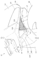
図5は本発明に係る自動二輪車のエア吸入口周りの斜視図であり、フロントカウル101に一体に形成した切込み部104が側面視で「く」の字を呈する形状であること、及び、エア吸入口103に入らぬエアWiを切込み部104に沿わせて流せるようにしたことを示す。
切込み部104は、下側傾斜面106及び上側傾斜面107からなる。これらの下・上側傾斜面106,107の側部コーナは比較的大きい曲面である。
【0033】
側面視でくの字を呈する切込み部104をフロントカウル101に且つエア吸入口103の外側に隣接して設け、エア吸入口103に入らぬエア(走行風)Wiを切込み部104に沿わせて流せるようにしたので、エア吸入口103に入らぬエアWiを整流しつつ後方へ流すことができる。従って、自動二輪車10の走行性能を高める上で有利である。
【0034】
下側傾斜面106は、正面から後方へ向って上向きとなる傾斜面である。このように傾斜した下側傾斜面106であるから、エアWiを通過させることによって、自動二輪車10を下方へ押え付けるための下向き力を発生させるエアスポイラの役割を果たすことができる。
【0035】
エア(走行風)Wiが下側傾斜面106に沿って後上方へ流れ、側部コーナを経て後方へ通過する。このように、エアWiが下側傾斜面106を通過することによって、自動二輪車10を下方へ押え付けるための下向き力Fdが発生する。この結果、走行時に発生する揚力Fuを下向き力Fdによって軽減することができる。従って、前輪32(図1参照)のタイヤのグリップ力を維持して、快適な高速走行性能を得ることができる。
【0036】
【発明の効果】
本発明は上記構成により次の効果を発揮する。
請求項1は、エア吸入口を、フロントフォークの左右の外側位置に各々設けたので、エア吸入口の開口面積を増す上で、周囲の他の部材のレイアウトの制限を受けにくい。このため、エア吸入口の開口面積を増してエアをエンジンへ十分に供給することができる。この結果、エンジン性能をより十分に発揮させることができる。
しかも、車幅中央にある前輪に対して、エア吸入口を左右に設けたので、前輪がもっとも持上がったときであっても、前輪にエア吸入口が干渉することはない。従って、エア吸入口の高さを上げる必要がないので、自動二輪車のデザイン上の制約がない。
さらには、側面視でくの字を呈する切込み部をカウリングに設け、且つ、切込み部の車体内側にエア吸入口の外側が隣接して設けられることで、エア吸入口に入らぬエアを切込み部に沿わせて流せるようにしたので、切込み部の車体内側、且つ、エア吸入口の外側を流れるエア吸入口に入らぬエアを整流しつつ後方へ流すことができる。従って、自動二輪車の走行性能を高める上で有利である。
請求項2では、切込み部は、下側傾斜面及び上側傾斜面から構成され、下側傾斜面は、正面から後方へ向って上向きとなる傾斜面なので、下側傾斜面に走行時のエアを通過させることによって、自動二輪車を下方へ押え付けるための下向き力を発生させる。この結果、走行時に発生する揚力を下向き力によって軽減することができる。従って、前輪のタイヤのグリップ力を維持して、快適な高速走行性能を得ることができる。
請求項3では、エア吸入口は、車体正面視、略三角形状で、前輪に向けた辺が湾曲しているので、前輪がもっとも持上がったときであっても、前輪にエア吸入口が干渉することはない。従って、エア吸入口の高さを上げる必要がないので、自動二輪車のデザイン上の制約がない。
【図面の簡単な説明】
【図1】本発明に係る自動二輪車の右側面図
【図2】本発明に係る自動二輪車の吸・排気系構造の要部斜視図
【図3】本発明に係るサイレンサの平面断面図
【図4】本発明に係る自動二輪車のエア吸入口周りの正面図
【図5】本発明に係る自動二輪車のエア吸入口周りの斜視図
【符号の説明】
10…自動二輪車、31…フロントフォーク、32…前輪、34…後輪、40…エンジン、51…吸気系、52…エアダクト、53…エアクリーナ、58…排気系、60…エキゾーストパイプ、61…第1パイプ、62…第2パイプ、63…第3パイプ、64…第4パイプ、65…第1集合筒、66…第2集合筒、67…第3集合筒、70…サイレンサ、73…ガス入口、74…ガス出口、100…カウリング、101…フロントカウル、103…エア吸入口、104…切込み部。[0001]
BACKGROUND OF THE INVENTION
The present invention relates to an air inlet structure of a motorcycle.
[0002]
[Prior art]
The intake system structure of a motorcycle is such that an air inlet is provided in a cowling that covers the front of the vehicle body, and the tip of an air duct extending from the air inlet is connected to an air cleaner. As such an exhaust system structure of a motorcycle, for example, Japanese Unexamined Patent Publication No. 9-86463 “Motorcycle” (hereinafter referred to as “Conventional Technology (1)”) is known.
[0003]
The above-mentioned prior art {circle around (1)}, as shown in FIGS. 1 to 3 of the publication, is the center position of the vehicle width at the front of the upper cowling 12 (the numbers are those cited in the publication; the same applies hereinafter). 1 is provided with a single air inlet 17, a branch duct 18 is extended rearward from the air inlet 17, and an air cleaner 16 is connected to the tip of the branch duct 18.
[0004]
However, the conventional technique {circle around (1)} has only one air inlet 17 at the center position of the vehicle width, so there is a limit to increasing the opening area of the air inlet 17.
Further, even when the front wheel 3 is lifted most, it is necessary to prevent the air inlet 17 from interfering with the front wheel 3. If the height of the air inlet 17 is increased so as not to interfere, the overall height of the motorcycle 1 also increases, which is not a good idea.
[0005]
In order to eliminate such a point, for example, a configuration as disclosed in Japanese Patent Application Laid-Open No. 2000-95168 “Motorcycle wind duct mounting structure of a motorcycle” (hereinafter referred to as “conventional technology (2)”) is adopted. Can be considered.
[0006]
In the prior art {circle around (2)}, as shown in FIGS. 1 and 2 of the same publication, two left and right air intakes 17 and 17 are provided at the front portion of the cowling 16, and rearward from these air intakes 17 and 17. The present invention relates to an intake system structure in which the traveling air ducts 18 and 18 are extended to the front and the air cleaner 7 is connected to the ends of the traveling air ducts 18 and 18. Traveling wind generated on the front surface of the cowling 16 during traveling of the motorcycle 1 can be taken in from the air intake ports 17 and 17.
According to the prior art {circle around (2)}, since the air intakes 17 and 17 are arranged on the left and right, it is advantageous in increasing the opening area of the air intakes 17 and 17, and the air intake 17 and 17 does not interfere.
[0007]
[Problems to be solved by the invention]
In the conventional technique (2), the traveling wind that does not enter the air intake ports 17 and 17 flows rearward along the cowling 16. However, the cowling 16 has an overall rounded and swollen shape. A traveling wind that does not enter the air intake ports 17 and 17 may hit the cowling 16 and become turbulent. Reducing such turbulent flow is advantageous for improving the running performance of the motorcycle 1.
The same applies to the conventional technique (1).
[0008]
Accordingly, the object of the present invention is to (1) increase the opening area of the air inlet provided in the cowling to sufficiently supply air to the engine, and (2) rearward while rectifying the air that does not enter the air inlet. It is to provide a technique that can be made to flow.
[0009]
[Means for Solving the Problems]
In order to achieve the above object, a first aspect of the present invention relates to a motorcycle in which an air suction port is provided in a cowling that covers a front portion of a vehicle body, and a tip of an air duct extending from the air suction port is connected to an air cleaner. A mouth is provided at each of the left and right outer positions of the front fork. It is characterized by being able to flow along.
[0010]
Since the air suction ports are provided at the left and right outer positions of the front fork, respectively, the area of the air suction port is increased, and the layout of other members is less likely to be limited. For this reason, the opening area of the air inlet can be increased and air can be sufficiently supplied to the engine. As a result, the engine performance can be more fully exhibited.
In addition, since the air suction ports are provided on the left and right of the front wheel in the center of the vehicle width, the air suction port does not interfere with the front wheels even when the front wheel is lifted most. Therefore, since there is no need to increase the height of the air inlet, there is no restriction on the design of the motorcycle.
In addition, a notch that has a cross-section in a side view is provided on the cowling and adjacent to the outside of the air inlet, so that air that does not enter the air inlet can flow along the notch. Air that does not enter the mouth can be rectified and flow backward. Therefore, it is advantageous for improving the running performance of the motorcycle.
According to a second aspect of the present invention, the cut portion includes a lower inclined surface and an upper inclined surface, and the lower inclined surface is an inclined surface that faces upward from the front to the rear.
A downward force for pressing the motorcycle downward is generated by passing air during traveling through a lower inclined surface, which is an inclined surface that faces upward from the front to the rear. As a result, the lift generated during traveling can be reduced by the downward force. Accordingly, it is possible to maintain a comfortable gripping performance of the front wheel tire and to obtain a comfortable high speed driving performance.
According to a third aspect of the present invention, the air suction port has a substantially triangular shape as viewed from the front of the vehicle body, and has a side that is curved toward the front wheel.
Even when the front wheel is lifted most, the air suction port does not interfere with the front wheel. Therefore, since there is no need to increase the height of the air inlet, there is no restriction on the design of the motorcycle.
[0011]
DETAILED DESCRIPTION OF THE INVENTION
Embodiments of the present invention will be described below with reference to the accompanying drawings.
Note that “front”, “rear”, “left”, “right”, “upper”, and “lower” follow the direction seen from the driver. The drawings are to be viewed in the direction of the reference numerals.
[0012]
FIG. 1 is a right side view of a motorcycle according to the present invention and shows an appearance of a
The
[0013]
The present invention is characterized in that the
[0014]
Further, the
[0015]
The
[0016]
The
Further, a
[0017]
Furthermore, this figure shows that the
[0018]
In the figure, 47 is a crankshaft of the engine, 48 is a cover member (crankshaft cover), 91 is a handle, 92 is a mirror, 93 is a headlamp, 94 is a blinker, 95 is a front fender, 96 is a rear cushion unit, 97 is This is a cushion link. The rear part of the
[0019]
FIG. 2 is a perspective view of an essential part of the intake / exhaust system structure of the motorcycle according to the present invention.
The
[0020]
The
The
[0021]
As the
[0022]
Here, the four exhaust ports are referred to as a
The
[0023]
The
[0024]
On the other hand, the
[0025]
Further, the other end of the
[0026]
FIG. 3 is a plan sectional view of the silencer according to the present invention.
The
[0027]
In this way, the
The exhaust noise can be attenuated by the expansion action when the exhaust gas enters the first, second, and
[0028]
Next, the operation of the
The
Moreover, since the
[0029]
FIG. 4 is a front view of the periphery of the air intake port of the motorcycle according to the present invention. Left and right
[0030]
Since the
[0031]
Moreover, since the
[0032]
FIG. 5 is a perspective view around the air intake port of the motorcycle according to the present invention, in which the
The
[0033]
A cut-out
[0034]
The lower
[0035]
Air (running wind) Wi flows rearward and upward along the lower
[0036]
【The invention's effect】
The present invention exhibits the following effects by the above configuration.
According to the first aspect of the present invention, since the air suction ports are provided at the left and right outer positions of the front fork, respectively, the layout area of other surrounding members is not easily restricted in increasing the opening area of the air suction port. For this reason, the opening area of the air inlet can be increased and air can be sufficiently supplied to the engine. As a result, the engine performance can be more fully exhibited.
In addition, since the air suction ports are provided on the left and right of the front wheel in the center of the vehicle width, the air suction port does not interfere with the front wheels even when the front wheel is lifted most. Therefore, since there is no need to increase the height of the air inlet, there is no restriction on the design of the motorcycle.
Furthermore, a notch that presents a cross-section in a side view is provided in the cowling , and the outside of the air suction port is provided adjacent to the inside of the car body of the notch , so that the air that does not enter the air suction port is notched. Therefore, the air that does not enter the air intake port that flows inside the vehicle body of the cut portion and outside the air intake port can be flown backward while being rectified. Therefore, it is advantageous for improving the running performance of the motorcycle.
In claim 2, the cut portion is composed of a lower inclined surface and an upper inclined surface, and the lower inclined surface is an inclined surface that faces upward from the front to the rear. By passing, a downward force for pressing the motorcycle downward is generated. As a result, the lift generated during traveling can be reduced by the downward force. Accordingly, it is possible to maintain a comfortable gripping performance of the front wheel tire and to obtain a comfortable high speed driving performance.
In claim 3, the air intake port has a substantially triangular shape when viewed from the front of the vehicle body, and the side toward the front wheel is curved. Therefore, even when the front wheel is lifted most, the air intake port interferes with the front wheel. Never do. Therefore, since there is no need to increase the height of the air inlet, there is no restriction on the design of the motorcycle.
[Brief description of the drawings]
FIG. 1 is a right side view of a motorcycle according to the present invention. FIG. 2 is a perspective view of a main part of a suction / exhaust system structure of a motorcycle according to the present invention. FIG. 3 is a plan sectional view of a silencer according to the present invention. 4] Front view around the air intake port of the motorcycle according to the present invention. [FIG. 5] Perspective view around the air intake port of the motorcycle according to the present invention.
DESCRIPTION OF
Claims (3)
前記エア吸入口は、フロントフォークの左右の外側位置に各々設け、側面視でくの字を呈する切込み部を前記カウリングに設け、且つ、前記切込み部の車体内側に前記エア吸入口の外側が隣接して設けられることで、エア吸入口に入らぬエアを前記切込み部に沿わせて流せるようにしたことを特徴とする自動二輪車のエア吸入口構造。In a motorcycle in which an air inlet is provided in a cowling that covers the front of the vehicle body, and the tip of an air duct extending from the air inlet is connected to an air cleaner.
The air inlet port, each provided outside the position of the left and right front forks, provided a cut portion presenting a shape in a side view Do the cowling, and the outer air inlet adjacent to the inboard of said notches to that provided, air inlet structure for a motorcycle, characterized in that as flown in and along the air which is not entering the air inlet to the cut portion.
Priority Applications (2)
| Application Number | Priority Date | Filing Date | Title |
|---|---|---|---|
| JP2001105698A JP3970543B2 (en) | 2001-04-04 | 2001-04-04 | Air intake structure of motorcycle |
| CNB021078300A CN1184100C (en) | 2001-04-04 | 2002-03-22 | Air intake structure of two-wheeled motor vehicle |
Applications Claiming Priority (1)
| Application Number | Priority Date | Filing Date | Title |
|---|---|---|---|
| JP2001105698A JP3970543B2 (en) | 2001-04-04 | 2001-04-04 | Air intake structure of motorcycle |
Publications (2)
| Publication Number | Publication Date |
|---|---|
| JP2002302083A JP2002302083A (en) | 2002-10-15 |
| JP3970543B2 true JP3970543B2 (en) | 2007-09-05 |
Family
ID=18958338
Family Applications (1)
| Application Number | Title | Priority Date | Filing Date |
|---|---|---|---|
| JP2001105698A Expired - Fee Related JP3970543B2 (en) | 2001-04-04 | 2001-04-04 | Air intake structure of motorcycle |
Country Status (2)
| Country | Link |
|---|---|
| JP (1) | JP3970543B2 (en) |
| CN (1) | CN1184100C (en) |
Families Citing this family (13)
| Publication number | Priority date | Publication date | Assignee | Title |
|---|---|---|---|---|
| CN100551766C (en) * | 2004-08-06 | 2009-10-21 | 光阳工业股份有限公司 | Wind hole device of motorcycle |
| JP4444868B2 (en) * | 2005-03-31 | 2010-03-31 | 本田技研工業株式会社 | Air intake duct structure |
| JP2007008357A (en) | 2005-06-30 | 2007-01-18 | Honda Motor Co Ltd | Air intake structure of motorcycle |
| JP2007261537A (en) * | 2006-03-29 | 2007-10-11 | Yamaha Motor Co Ltd | Motorcycle |
| CN101104427B (en) * | 2006-07-10 | 2011-06-29 | 重庆宗申技术开发研究有限公司 | Motorcycle capable of conveniently carrying different shaping style assembling |
| JP2009083679A (en) * | 2007-09-28 | 2009-04-23 | Honda Motor Co Ltd | Cowl structure of motorcycle |
| EP2311717B1 (en) * | 2008-08-08 | 2014-02-12 | Honda Motor Co., Ltd. | Vehicle |
| JP5555586B2 (en) * | 2010-09-29 | 2014-07-23 | 本田技研工業株式会社 | Fairing structure for saddle-ride type vehicles |
| JP5922641B2 (en) * | 2013-12-26 | 2016-05-24 | 本田技研工業株式会社 | Motorcycle body cover structure |
| JP6117831B2 (en) * | 2015-01-29 | 2017-04-19 | 本田技研工業株式会社 | Air intake structure for saddle-ride type vehicles |
| JP6447383B2 (en) * | 2015-06-17 | 2019-01-09 | スズキ株式会社 | Suction type vehicle intake structure |
| JP6894696B2 (en) * | 2016-12-08 | 2021-06-30 | 川崎重工業株式会社 | Saddle-type vehicle |
| GB2564091A (en) * | 2017-06-13 | 2019-01-09 | Tunley Eng | Variable down force motorcycle fairing device |
-
2001
- 2001-04-04 JP JP2001105698A patent/JP3970543B2/en not_active Expired - Fee Related
-
2002
- 2002-03-22 CN CNB021078300A patent/CN1184100C/en not_active Expired - Fee Related
Also Published As
| Publication number | Publication date |
|---|---|
| CN1184100C (en) | 2005-01-12 |
| CN1378942A (en) | 2002-11-13 |
| JP2002302083A (en) | 2002-10-15 |
Similar Documents
| Publication | Publication Date | Title |
|---|---|---|
| JP3889236B2 (en) | Exhaust system structure of motorcycle | |
| JP3723792B2 (en) | Air intake device for vehicle engine | |
| JP4429429B2 (en) | Motorcycle cowling device | |
| JP3970543B2 (en) | Air intake structure of motorcycle | |
| JP6447383B2 (en) | Suction type vehicle intake structure | |
| JP4367878B2 (en) | Intake duct for motorcycle | |
| JP2000335466A (en) | Air cleaner arrangement structure of motorcycle | |
| JP4028691B2 (en) | Motorcycle cowling structure | |
| JP3836224B2 (en) | Motorcycle cowling device | |
| JP3727641B2 (en) | Motorcycle exhaust system | |
| JP2020116979A (en) | Saddle-riding type vehicle | |
| JP4383002B2 (en) | Rear fender structure of motorcycle | |
| JP4153585B2 (en) | Motorcycle cooling device | |
| JP2007008357A (en) | Air intake structure of motorcycle | |
| JP2617114B2 (en) | Exhaust system for automobile engine | |
| JP7344947B2 (en) | Air cleaner structure for saddle type vehicles | |
| JP4000188B2 (en) | Air vent tube holding structure of vaporizer | |
| JP5850733B2 (en) | Engine intake system | |
| JP4494679B2 (en) | Intake device for motorcycle | |
| JP3801254B2 (en) | Motorcycle cooling device | |
| WO2023148755A1 (en) | A saddle type vehicle | |
| JPH0343116Y2 (en) | ||
| JPH02197481A (en) | Air intake device for motorcycle | |
| JP2023088020A (en) | Saddle-riding type vehicle | |
| JP4394554B2 (en) | Radiator arrangement structure of motorcycle |
Legal Events
| Date | Code | Title | Description |
|---|---|---|---|
| A621 | Written request for application examination |
Free format text: JAPANESE INTERMEDIATE CODE: A621 Effective date: 20041203 |
|
| A977 | Report on retrieval |
Free format text: JAPANESE INTERMEDIATE CODE: A971007 Effective date: 20070130 |
|
| A131 | Notification of reasons for refusal |
Free format text: JAPANESE INTERMEDIATE CODE: A131 Effective date: 20070313 |
|
| A521 | Request for written amendment filed |
Free format text: JAPANESE INTERMEDIATE CODE: A523 Effective date: 20070509 |
|
| TRDD | Decision of grant or rejection written | ||
| A01 | Written decision to grant a patent or to grant a registration (utility model) |
Free format text: JAPANESE INTERMEDIATE CODE: A01 Effective date: 20070605 |
|
| A61 | First payment of annual fees (during grant procedure) |
Free format text: JAPANESE INTERMEDIATE CODE: A61 Effective date: 20070606 |
|
| R150 | Certificate of patent or registration of utility model |
Free format text: JAPANESE INTERMEDIATE CODE: R150 |
|
| FPAY | Renewal fee payment (event date is renewal date of database) |
Free format text: PAYMENT UNTIL: 20110615 Year of fee payment: 4 |
|
| FPAY | Renewal fee payment (event date is renewal date of database) |
Free format text: PAYMENT UNTIL: 20110615 Year of fee payment: 4 |
|
| FPAY | Renewal fee payment (event date is renewal date of database) |
Free format text: PAYMENT UNTIL: 20130615 Year of fee payment: 6 |
|
| FPAY | Renewal fee payment (event date is renewal date of database) |
Free format text: PAYMENT UNTIL: 20130615 Year of fee payment: 6 |
|
| FPAY | Renewal fee payment (event date is renewal date of database) |
Free format text: PAYMENT UNTIL: 20140615 Year of fee payment: 7 |
|
| LAPS | Cancellation because of no payment of annual fees |